

Page 1
SS-WG880
A
SERVICE MANUAL
Ver 1.0 2004. 04
• SS-WG880 is the subwoofer section
in MHC-GN880.
SPECIFICATIONS
Subwoofer system 1-way, 1-unit, bass-reflex type
Speaker units
Sub Woofer 20 cm, cone type
Nominal impedance 8 ohms
Dimensions (w/h/d) (Approx.) 265 x 430 x 320 mm
Mass (Approx.) 7.4 kg
E Model
Australian Model
SECTION 1
GENERAL
This section is extracted
from instruction manual.
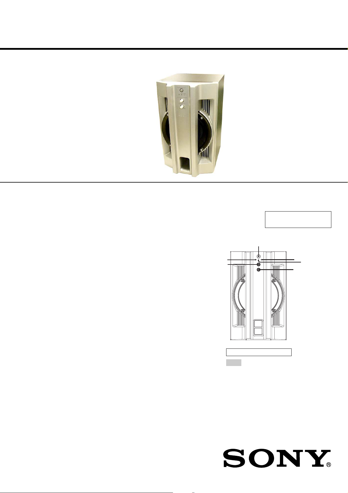
LOCA TING THE CONTROLS
Design and specifications are subject to change without notice.
6
E
ALPHABETICAL ORDER
A – Z
LINK (indicator) 6
MATRIX SURR 1 (indicator)
MATRIX SURR 2 (indicator)
SUBWOOFER LEVEL 4
SUBWOOFER ON/OFF 1
SURROUND SPEAKER MODE
3
2
5
B
D
C
9-877-803-01
2004D02-1
© 2004.04
SUBWOOFER SYSTEM
Sony Corporation
Home Audio Company
Published by Sony Engineering Corporation
Page 2
SS-WG880
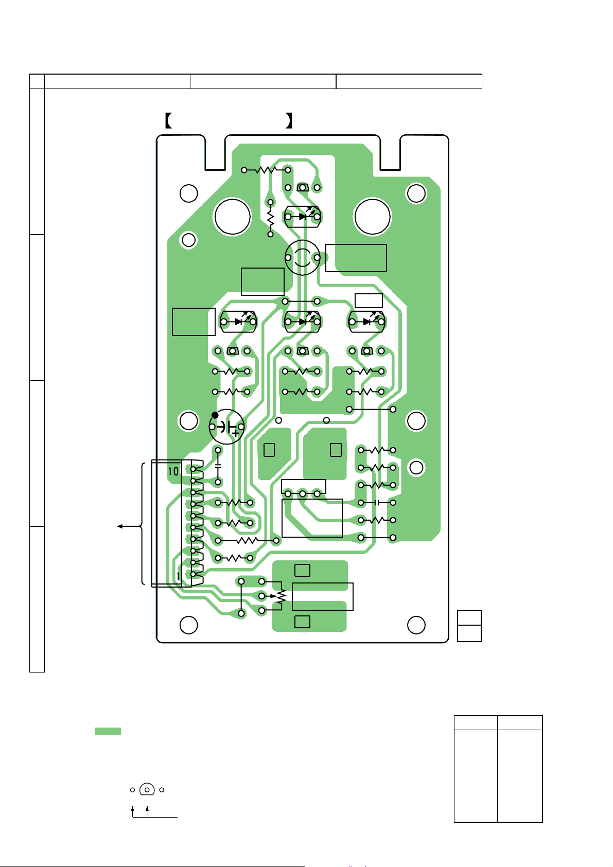
2-1. PRINTED WIRING BOARD
1
SECTION 2
DIAGRAMS
2
BOARDSW PANEL
3
A
B
C
HCD-GN880
MATRIX
SURR 2
CN101
D106
Q106
R116
R106
C102
C103
R125
R126
R127
R115
R105
D108
MATRIX
SURR 1
E
Q105
E
D105
JW101
Q108
E
R118
R108
S101
1 2 3
SURROUND
SPEAKR
MODE
S102
SUBWOOFER
ON/OFF
D107
LINK
Q107
R117
R107
JW102
R101
R102
R103
C101
R104
JW103
E
R128
RV101
SUBWOOFER
D
JW104
LEVEL
11
Note on Printed Wiring Boards:
• X : parts extracted from the component side.
• : Pattern from the side which enables seeing.
(The other layers' patterns are not indicated.)
• Indication of transistor.
Q
B
CE
These are omitted.
1-862-762-
(11)
• Semiconductor
Location
Ref. No. Location
D105 A-2
D106 B-2
D107 B-3
D108 B-2
Q105 A-2
Q106 B-2
Q107 B-3
Q108 B-2
2
Page 3

2-2. SCHEMATIC DIAGRAM
RV101
50k
SUBWOOFER
LEVEL
SS-WG880
CN101
C103
0.1
D105
SEL 5923A-TP15
SUBWOOFER
ON/OFF
R125
10k
R115
10k
R101
100k
R105
Q105
2SC2785TP-FEK
SUBWOOFER
R126
10k
180
R102
2.2k
S102
ON/OFF
D106
SEL 5923A-TP15
MATRIX
SURR 2
R116
10k
R103
4.7k
R106
180
2SC2785TP-FEK
Q105-108
LED
DRIVER
C101
100p
D107
SEL 5923A-TP15
LINK
R128
10k
R127
10k
Q106
R117
10k
R104
10k
2SC2785TP-FEK
2SC2785TP-FEK
R107
180
S101
SURROUND
SPEAKER
MODE
D108
SEL 5923A-TP15
MATRIX
SURR 1
Q108
Q107
R118
10k
R108
180
C102
100
10V
Note on Schematic Diagram:
• All capacitors are in µF unless otherwise noted. (p: pF) 50 WV or
less are not indicated except for electrolytics and tantalums.
• All resistors are in Ω and 1/4 W or less unless otherwise specified.
• C : panel designation.
• A : B+ Line.
•Voltages and waveforms are dc with respect to ground in service
mode.
no mark : POWER ON
•Voltages are taken with a VOM (Input impedance 10 MΩ).
Voltage variations may be noted due to normal production tolerances.
3
Page 4

SS-WG880
NOTE:
• -XX, -X mean standardized parts, so they may
have some differences from the original one.
• Items marked “*” are not stocked since they
are seldom required for routine service. Some
delay should be anticipated when ordering these
items.
3
SECTION 3
EXPLODED VIEWS
SP1
8
6
7
7
2
5
not supplied
2
4
not supplied
not supplied
1
Ref. No. Part No. Description Remarks
1 A-4713-731-A FRONT PANEL ASSY
2 4-986-911-11 SCREW (3.5)
3 4-874-614-02 SCREW (1) (3.5X14), TAPPING
4 2-022-110-01 KNOB, LEVEL
5 2-022-109-01 KNOB, MODE
4
Ref. No. Part No. Description Remarks
6 1-862-762-11 SW PANEL BOARD
7 4-951-620-01 SCREW (2.6X8), +BVTP
8 1-824-107-13 CORD, CONECTION
SP1 1-825-921-11 SPEAKER (20cm)
Page 5

SECTION 4
ELECTRICAL PARTS LIST
SS-WG880
SW PANEL
NOTE:
• Due to standardization, replacements in the
parts list may be different from the parts
specified in the diagrams or the components
used on the set.
• -XX, -X mean standardized parts, so they
may have some difference from the original
one.
• Items marked “*” are not stocked since they
are seldom required for routine service.
Some delay should be anticipated when
ordering these items.
• CAPACITORS:
uF: µF
Ref. No. Part No. Description Remarks Ref. No. Part No. Description Remarks
1-862-762-11 SW PANEL BOARD
**************
< CAPACITOR >
C101 1-162-282-31 CERAMIC 100PF 10% 50V
C102 1-124-584-00 ELECT 100uF 20% 10V
C103 1-164-159-11 CERAMIC 0.1uF 50V
< CONNECTOR >
CN101 1-785-336-11 PIN, CONNECTOR (LIGHT ANGLE) 10P
< DIODE >
• RESISTORS
All resistors are in ohms.
METAL: metal-film resistor
METAL OXIDE: Metal Oxide-film resistor
F: nonflammable
• COILS
uH: µH
•SEMICONDUCTORS
In each case, u: µ, for example:
uA...: µA... , uPA... , µPA... ,
uPB... , µPB... , uPC... , µPC... ,
uPD..., µPD...
R104 1-249-429-11 CARBON 10K 5% 1/4W
R105 1-249-408-11 CARBON 180 5% 1/4W
R106 1-249-408-11 CARBON 180 5% 1/4W
R107 1-249-408-11 CARBON 180 5% 1/4W
R108 1-249-408-11 CARBON 180 5% 1/4W
R115 1-249-429-11 CARBON 10K 5% 1/4W
R116 1-249-429-11 CARBON 10K 5% 1/4W
R117 1-249-429-11 CARBON 10K 5% 1/4W
R118 1-249-429-11 CARBON 10K 5% 1/4W
R125 1-249-429-11 CARBON 10K 5% 1/4W
R126 1-249-429-11 CARBON 10K 5% 1/4W
R127 1-249-429-11 CARBON 10K 5% 1/4W
When indicating parts by reference
number, please include the board.
D105 8-719-057-97 DIODE SEL5923A-TP15 (SUBWOOFER ON/OFF)
D106 8-719-057-97 DIODE SEL5923A-TP15 (MATRIX SURR2)
D107 8-719-057-97 DIODE SEL5923A-TP15 (LINK)
D108 8-719-057-97 DIODE SEL5923A-TP15 (MATRIX SURR1)
< TRANSISTOR >
Q105 8-729-119-79 TRANSISTOR 2SC2785-FEK
Q106 8-729-119-79 TRANSISTOR 2SC2785-FEK
Q107 8-729-119-79 TRANSISTOR 2SC2785-FEK
Q108 8-729-119-79 TRANSISTOR 2SC2785-FEK
< RESISTOR >
R101 1-247-879-91 CARBON 100K 5% 1/4W
R102 1-249-421-11 CARBON 2.2K 5% 1/4W
R103 1-247-847-91 CARBON 4.7K 5% 1/4W
R128 1-249-429-11 CARBON 10K 5% 1/4W
< VARIABLE RESISTOR >
RV101 1-225-406-11 RES, VAR, CARBON 50K
(SUBWOOFER LEVEL)
< SWITCH >
S101 1-477-526-11 ENCODER, ROTARY
(SURROUND SPEAKER MODE)
S102 1-771-410-21 SWITCH, TACTILE (SUBWOOFER ON/OFF)
5
Page 6

SS-WG880
REVISION HISTORY
Clicking the version allows you to jump to the revised page.
Also, clicking the version at the upper right on the revised page allows you to jump to the next revised
page.
Ver. Date Description of Revision
1.0 2004.04 New
 Loading...