

Page 1

3-709-285-12 (1)
Black and White Monitor
Operating Instructions Page 2
Mode d'emploi Page 12
SSM-175A
© 1997 by Sony Corporation
Page 2
English
Owner’s Record
The model and serial numbers are located at the rear.
Record the serial number in the space provided below.
Refer to these numbers whenever you call upon your Sony
dealer regarding this product.
Model No. SSM-175A Serial No. ______________
WARNING
To prevent fire or shock hazard, do not expose the
unit to rain or moisture.
This symbol is intended to alert the user to
the presence of uninsulated “dangerous
voltage” within the product’s enclosure that
may be of sufficient magnitude to constitute
a risk of electric shock to persons.
This symbol is intended to alert the user to
the presence of important operating and
maintenance (servicing) instructions in the
literature accompanying the appliance.
CAUTION:
TO PREVENT ELECTRIC SHOCK, DO NOT USE THIS
POLARIZED AC PLUG WITH AN EXTENSION CORD,
RECEPTACLE OR OTHER OUTLET UNLESS THE
BLADES CAN BE FULLY INSERTED TO PREVENT
BLADE EXPOSURE.
This unit is not intended to be used with computer work
stations.
2
Page 3

For the customers in the U.S.A.
This equipment has been tested and found to comply with
the limits for a Class A digital device, pursuant to Part 15 of
the FCC Rules. These limits are designed to provide
reasonable protection against harmful interference when the
equipment is operated in a commercial environment. This
equipment generates, uses, and can radiate radio frequency
energy and, if not installed and used in accordance with the
instruction manual, may cause harmful interference to radio
communications. Operation of this equipment in a residential
area is likely to cause harmful interference in which case the
user will be required to correct the interference at his own
expense.
You are cautioned that any changes or modifications not
expressly approved in this manual could void your authority
to operate this equipment.
For the customers in Canada
The Class A digital apparatus meets all requirements of the
Canadian Interference-Causing Equipment Regulations.
CAUTION:
English
These potential hazards shall be considered common to
most rack installation.
1) Elevated Operating Ambient Temperature
After installed, the operating temperature may be greater
than room ambient. Consideration shall be given to the
environment temperature compatible within the
Manufacturer’s specified limit of Ambient Temperature of
0°C – +35°C.
2) Reduced Air Flow
After installed, the amount of air flow required for safe
operation of this equipment shall not compromised.
3) Circuit Overloading
Before installing, refer to rated current on this equipment
and make sure that no overloading to the supply circuit
on the rack.
Please confirm the rated current described on this
Operating Instructions.
4) Providing Protective Earth
When this product is installed in a rack and supplied
power from an outlet on the rack, please confirm that the
outlet is provided with a reliable protective earth
connection.
5) Prevention against achieving hazardous condition
due to uneven mechanical loading
When this product is in a rack, please make sure that the
rack does not achieve hazardous condition due to
uneven mechanical loading.
3
Page 4

Table of Contents
Before operating the unit, please read this manual
thoroughly and retain it for future reference.
Features .............................................................................. 4
Precautions......................................................................... 5
Location and Function of Controls .................................. 6
Front Panel ...................................................................... 6
Rear Panel ....................................................................... 7
Connections ........................................................................ 8
Connecting a Video Camera or a VCR ........................... 8
Connecting the Monitors................................................. 9
Specifications.................................................................... 10
Features
• This unit can be used as a closed circuit television monitor
or a video preview/playback monitor.
• Loop through connection allows up to three monitors to
display the same picture.
• Electronic circuits provide safeguards against interference,
noise and change of signal strength to maintain a clear and
stable picture.
• This unit can be mounted in an EIA standard rack.
4
Page 5

Precautions
Safety
• The unit operates on 120 V AC, 60 Hz.
• Should any liquid or solid object fall into the cabinet,
unplug the unit and have it checked by qualified personnel
before operating it any further.
• Unplug the unit from the wall outlet if it is not going to be
used for several days or more. To disconnect the cord,
pull it out by the plug. Never pull the cord itself.
• Allow adequate air circulation to prevent internal heat
build-up. Do not place the unit on surfaces (rugs,
blankets, etc.) or near materials (curtains, draperies) that
may block the ventilation holes.
• Height and vertical linearity controls located at the rear
panel are for special adjustments by qualified personnel
only.
Installation
• Do not install the unit in an extremely hot or humid place
or in a place subject to excessive dust or mechanical
vibration.
• The unit is not designed to be waterproof. Exposure to
rain or water may damage the unit.
Cleaning
Clean the unit with a lightly damp soft cloth. Use a mild
household detergent. Never use strong solvents such as
thinner or benzine as they might damage the finish of the
unit.
If you have any question or problem concerning your unit
that is not covered in this manual, please consult your
nearest Sony dealer.
5
Page 6
Location and Function of Controls
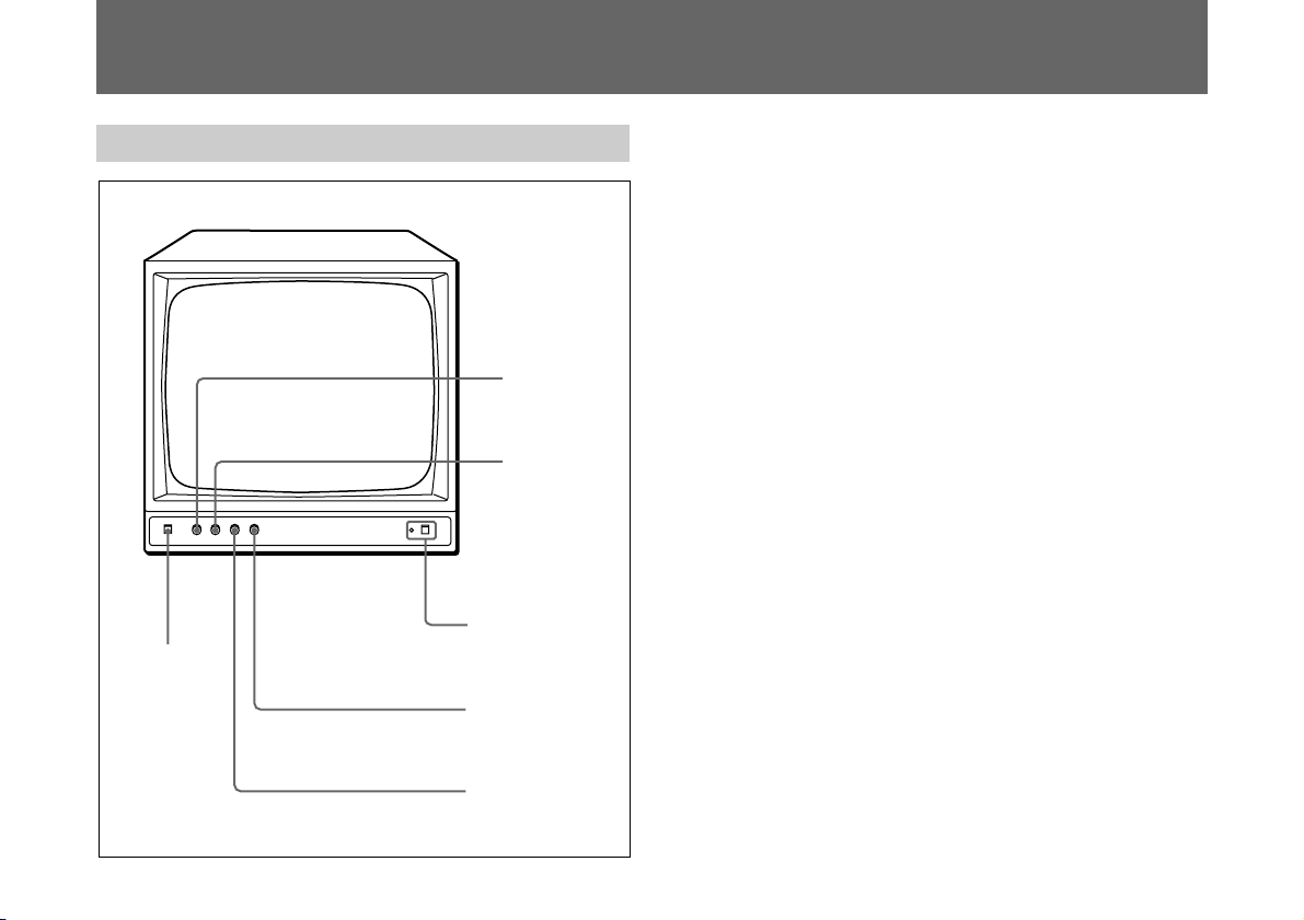
Front Panel
1
INPUT
select
switch
H-Hold
2
control
V-HOLD
3
control
4
POWER switch
and indicator
CONTRAST
5
control
6
BRIGHT control
1 INPUT select switch
Keep this switch released (øA) to monitor the signal from
the VIDEO A IN connector.
Depress this switch (ØB) to monitor the signal from the
VIDEO B IN connector.
2 H-HOLD (horizontal hold) control
When the picture has slanting horizontal bars, turn the HHOLD control in either direction until a stationary picture is
obtained.
3 V-HOLD (vertical hold) control
When the picture rolls up or down on the screen, turn the VHOLD control until a single stationary pictures is obtained.
4 POWER switch and indicator
To turn on the monitor, depress this switch. The green
indicator lights up.
To turn off the monitor, press the switch again.
5 CONTRAST control
Turn clockwise to increase picture contrast and
counterclockwise to decrease it.
6 BRIGHT (brightness) control
Turn clockwise for a brighter picture and counterclockwise
for a darker picture.
6
Page 7

Rear Panel
ON OFF
IN
VIDEO A
7
connectors and
75Ω ON/OFF
switch
OUT
VIDEO B
8
connectors
and 75Ω ON/
OFF switch
VIDEO BVIDEO A DC CLAMP
ON OFF ON OFF
IN
DC CLAMP ON/OFF switch
9
7 VIDEO A connectors and 75Ω ON/OFF switch
8 VIDEO B connectors and 75Ω ON/OFF switch
Two video input connectors (VIDEO A and VIDEO B) for
the composite video signals and their loop-through output
connectors.
To monitor the signals input to the VIDEO A IN connector,
keep the INPUT select switch released (øA).
To monitor the signals input to the VIDEO B IN connector,
keep the INPUT select switch released (ØB).
IN connector (BNC type)
Connect the video output of a VCR, video camera, or
another monitor for loop-through connection.
OUT connector (BNC type)
Connect the video input of a VCR, video camera, or another
monitor for loop-through connection.
75Ω ON/OFF switch
Set this switch to ON when only the IN connector is used.
Set this switch to OFF, when both the IN and OUT
connectors are used together for a loop-through connection.
OUT
9 DC CLAMP ON/OFF switch
When the switch is set to OFF, the black and white areas
may become slightly gray.
To reproduce clear black and white definition, set this switch
to ON.
7
Page 8

Connections
Connecting a Video Camera or a VCR
Connect the VIDEO IN connector to the video output of a
video camera or a VCR.
Video camera
to video output
VIDEO BVIDEO A DC CLAMP
VCR
Video camera
ON OFF
IN
to video output
ON OFF ON OFF
OUT
IN
OUT
VCR
8
Page 9

Connecting the Monitors
Using the loop-through feature of this unit, the same picture
can be obtained on all the monitors connected. You can
connect up to three monitors.
Video camera
to video output
ON OFF
IN
OFF OFF ON
ON OFF ON OFF
OUT
First monitor Second monitor Third monitor
VIDEO BVIDEO A DC CLAMP
ON OFF
OUT
IN
OUT
IN
Adjust the picture contrast and brightness of each monitor.
VIDEO BVIDEO A DC CLAMP VIDEO BVIDEO A DC CLAMP
ON OFF ON OFF
IN
OUT
ON OFF
IN
ON OFF ON OFF
OUT
IN
OUT
9
Page 10

Specifications
General
System EIA standard
Picture tube 17-inch picture measured
diagonally
90-degree deflection
Resolution More than 850 TV line
(horizontal)
Video input Composite: 0.5 – 2 Vp-p, sync
negative (×2)
Video input impedance High impedance for loop-
through; 75Ω terminated
Video output Composite: 0.5 – 2 Vp–p, sync
negative (×2)
Video output impedance Over 10 kΩ
Power requirements 120 V AC, 60 Hz
Power consumption Approximately 35W
Operating temperature 0°C to +35°C (32°F to 95°F)
Storage temperature –10°C to +40°C (14°F to 104°F)
Dimensions 424 × 409 ×380 mm (w/h/d)
(16 3/4 × 16 1/8 × 15 inches)
Mass Approx. 17.5 kg (38 lb 5 oz)
Supplied Accessory Operating Instructions (1)
Optional Accessory Mounting Bracket RMM-171
Design and specifications are subject to change without
notice.
10
Page 11

11
Page 12

Français
Table des matières
Avant d’utiliser le moniteur, veuillez lire attentivement ce
manuel et le conserver à titre de référence ultérieure.
AVERTISSEMENT
Afin d’éviter tout risque d’incendie ou
d’électrocution, ne pas exposer cet appareil à la
pluie ou à l’humidité.
Des courants de hautes tensions dangereuses
sont présents à l’intérieur de cet appareil. Ne pas
ouvrir le coffret. Se reporter à un personnel
qualifié uniquement.
Cet appareil n’est pas conçu pour être utilisé avec un
ordinateur.
Pour les utilisateurs au Canada
Cet appareil numérique de la classe A respecte toutes les
exigences du Réglement sur le brouillage du Canada.
Fonctionnalités................................................................. 12
Précautions....................................................................... 13
Localisation des commandes ..........................................14
Panneau avant ............................................................... 14
Panneau arrière.............................................................. 15
Raccordements................................................................. 16
Raccordement avec une caméra vidéo ou un
magnétoscope................................................................ 16
Raccordement de plusieurs moniteurs .......................... 17
Caractéristiques techniques............................................ 18
Fonctionnalités
• Ce moniteur peut être utilisé en circuit fermé, comme un
écran de télévision, ou comme moniteur vidéo pour
visualiser des images en direct et visionner des images
enregistrées.
• Le branchement en boucle permet à trois moniteurs
d’afficher la même image simultanément.
• Les circuits électroniques filtrent les interférences, le bruit
et s’adaptent au niveau du signal pour fournir une image
stable de qualité constante.
• Ce moniteur peut être monté sur une étagère standard
EIA.
12
Page 13

Précautions
Sécurité
Français
Entretien
• L’appareil fonctionne sur courant alternatif en 120 V (60
Hz).
• Si un liquide ou objet quelconque venait à s’introduire
dans l’appareil, débranchez immédiatement le cordon
d’alimentation et faites vérifier l’appareil par un
technicien qualifié avant de le remettre en service.
• Débranchez l’appareil si vous ne comptez pas l’utiliser
pendant plusieurs jours ou davantage. Débranchez le
cordon d’alimentation en tirant sur la fiche, jamais sur le
cordon lui-même.
• Pour éviter toute surchauffe interne, évitez de boucher les
orifices de ventilation ou de placer l’appareil à proximité
de matériaux qui pourraient boucher ces orifices.
• Les commandes de hauteur et de linéarité verticale,
situées dans le panneau arrière, sont destinées à des
réglages particuliers qui ne peuvent être effectués que par
un technicien qualifié.
Installation
• N’installez pas l’appareil dans un local surchauffé, trop
humide, poussiéreux, ou encore, soumis à des vibrations
d’origine mécanique.
• L’appareil n’a pas été conçu pour être résistant à l’eau. La
pluie ou des éclaboussures peuvent l’endommager.
Nettoyez l’appareil à sec avec un chiffon doux. N’utilisez
jamais de solvant trop puissant, de type dissolvant ou
benzine; vous risqueriez d’abîmer la finition extérieure de
l’appareil.
Pour toute question ou problème concernant cet appareil,
veuillez vous adresser à votre revendeur Sony le plus
proche.
13
Page 14

Localisation des commandes
Panneau avant
1
Touche de
sélection de
l’entrée
(INPUT)
Commande de
2
synchronisation
horizontale
(H-HOLD)
Commande de
3
synchronisation
verticale
(V-HOLD)
Touche et témoin
4
de mise sous
tension (POWER)
Commande de
5
contraste
(CONTRAST)
Commande de
6
luminosité
(BRIGHT)
1 Touche de sélection de l’entrée (INPUT)
Maintenez cette touche sortie (øA) pour recevoir le signal
provenant de l’entrée VIDEO A IN, et enfoncée (ØB) pour
recevoir le signal provenant de l’entrée VIDEO B IN.
2 Commande de synchronisation horizontale
(H-HOLD)
Ce bouton permet, en le tournant dans le sens approprié, de
stabiliser le défilement horizontal de l’image.
3 Commande de synchronisation verticale (V-HOLD)
Ce bouton permet, en le tournant dans le sens approprié, de
stabiliser le défilement vertical de l’image.
4 Touche et témoin de mise sous tension (POWER)
Appuyez sur cette touche pour mettre le moniteur sous
tension. Le témoin vert s’allume. Pour éteindre l’appareil,
appuyez à nouveau sur la touche.
5 Commande de contraste (CONTRAST)
Tournez dans le sens des aiguilles d’une montre pour
augmenter le contraste de l’image.
6 Commande de luminosité (BRIGHT)
Tournez dans le sens des aiguilles d’une montre pour
augmenter la luminosité de l’image.
14
Page 15

Panneau arrière
Entrée/sortie VIDEO
78
A et touche de
marche/arrêt 75
Ohms (ON/OFF)
ON OFF
IN
OUT
Entrée/sorie VIDEO
B et touche de
marche/arrêt 75
Ohms (ON/OFF)
VIDEO BVIDEO A DC CLAMP
ON OFF ON OFF
IN
Touche de marche/arrêt du circuit de
9
verrouillage (DC CLAMP ON/OFF)
OUT
7 Entrée/sortie VIDEO A et touche de marche/arrêt 75
Ohms (ON/OFF)
8 Entrée/sorie VIDEO B et touche de marche/arrêt 75
Ohms (ON/OFF)
Deux entrées vidéo (VIDEO A et VIDEO B) et deux sorties
pour le fonctionnement en boucle.
Maintenez la touche de sélection de l’entrée (INPUT) sortie
(øA) pour recevoir le signal provenant de l’entrée VIDEO
A IN.
Maintenez la touche de sélection de l’entrée (INPUT)
enfoncée (ØB) pour recevoir le signal provenant de l’entrée
VIDEO B IN.
Connecteur d’entrée (IN) de type BNC
Permet de raccorder la sortie d’un magnétoscope, d’une caméra
vidéo ou d’un autre moniteur (fonctionnement en boucle).
Connecteur de sortie (OUT) de type BNC
Permet de raccorder l’entrée d’un magnétoscope, d’une caméra
vidéo ou d’un autre moniteur (fonctionnement en boucle).
Touche de marche/arrêt 75 Ohms (ON/OFF)
Mettez cette touche en position marche (ON) lorsque vous
ne voulez utiliser que l’entrée vidéo (IN). Mettez cette
touche en position arrêt lorsque vous voulez utiliser l’entrée
et la sortie vidéo (fonctionnement en boucle).
9 Touche de marche/arrêt du circuit de verrouillage
(DC CLAMP ON/OFF)
Lorsque la touche est en position arrêt (OFF), les zones de
l’écran comportant du blanc et du noir mélangés peuvent
devenir grises. Pour reproduire la définition initiale de
l’image, mettez cette touche en position marche (ON).
15
Page 16

Raccordements
Raccordement avec une caméra vidéo ou un magnétoscope
Raccordez la sortie de la caméra ou du magnétoscope et
l’entrée du moniteur (VIDEO IN).
16
Caméra vidéo
Magnétoscope
Caméra vidéo
Magnétoscope
Vers la sortie vidéo
Vers la sortie vidéo
ON OFF
IN
ON OFF ON OFF
OUT
VIDEO BVIDEO A DC CLAMP
IN
OUT
Page 17

Raccordement de plusieurs moniteurs
La fonction boucle de cet appareil permet d’obtenir la même
qualité d’image sur tous les moniteurs reliés. Vous pouvez
relier jusqu’à trois moniteurs.
Caméra vidéo
Vers la sortie vidéo
ON OFF
IN
OFF OFF ON
OUT
Premier moniteur
VIDEO BVIDEO A DC CLAMP
ON OFF ON OFF
IN
ON OFF
OUT
OUT
IN
Réglez le contraste et la luminosité de chanque moniteur.
Deuxième moniteur
VIDEO BVIDEO A DC CLAMP VIDEO BVIDEO A DC CLAMP
ON OFF ON OFF
IN
ON OFF
OUT
OUT
IN
Troisième moniteur
ON OFF ON OFF
IN
OUT
17
Page 18

Caractéristiques techniques
Caractéristique
Système Standard EIA
Tube image Diagonale d’image: 17 pouces
Déflexion: 90 degrés
Résolution Supérieure à 850 lignes
télévision (Horizontale)
Entrée vidéo Composée: 0,5 – 2 Vcc, synchro
négative (×2)
Impédance entrée vidéo Haute impédance en
fonctionnement en boucle;
sortie 75 Ohms
Sortie vidéo Composée: 0,5 – 2 Vcc, synchro
négative (×2)
Impédance sortie vidéo Supérieure à 10 kOhms
Alimentation électrique 120 V A/C, 60 Hz
Consommation électrique Env. 35 W
Temp. de fonctionnement 0°C à +35°C (32°F à 95°F)
Temp. de stockage –10°C à +40°C (14°F à 104°F)
Dimensions 424 × 409 × 380 mm (l/h/p)
(16 3/4 × 16 1/8 × 15 pouces)
Poids Environ. 17,5 kg (38 lb 5 oz)
Accessoire fourni Mode d’emploi (1)
Accessoire non fourni Support de monture RMM-171
La conception et les specifications des éléments repris cidessus peuvent être modifiées sans préavis.
18
Page 19

19
Page 20

Sony Corporation Printed in Korea
 Loading...