

Page 1
SERVICE MANUAL
SIIA
CHASSIS
MODEL
…………… ……… …………………
PVM-14N5A
PVM-14N5E
PVM-14N5MDE
PVM-14N5U
PVM-14N6A
PVM-14N6E
PVM-14N6U
SSM-14N5A
SSM-14N5E
SSM-14N5U
DEST . CHASSIS NO.
AUS SCC-N87D-A
AEP SCC-N86C-A
AEP SCC-N86F-A
US/CND SCC-N84B-A
AUS SCC-N87C-A
AEP SCC-N86B-A
US/CND SCC-N84A-A
AUS SCC-N87A-A
AEP SCC-N86A-A
US/CND SCC-N84E-A
MODEL
…………… ……… …………………
PVM-20N5A
PVM-20N5E
PVM-20N5U
PVM-20N6A
PVM-20N6E
PVM-20N6U
SSM-20N5A
SSM-20N5E
SSM-20N5U
DEST . CHASSIS NO.
AUS SCC-N87F-A
AEP SCC-N86E-A
US/CND SCC-N84D-A
AUS SCC-N87E-A
AEP SCC-N86D-A
US/CND SCC-N84C-A
AUS SCC-N87B-A
AEP SCC-N86G-A
US/CND SCC-N84F-A
TRINITRON® COLOR VIDEO MONITOR
Page 2
! W ARNING
This manual is intended for qualified service personnel
only .
T o reduce the risk of electric shock, fire or injury , do not
perform any servicing other than that contained in the
operating instructions unless you are qualified to do so.
Refer all servicing to qualified service personnel.
(PVM-14N5MDE only)
Electromagnetic
Compatibility
This device compiles with the requirements of Directive 89/336/EEC
concerning electromagnetic compatibility.
This device meets EN50081-1/92 and EN50082-1/92.
WARNING!!
AN ISOLATION TRANSFORMER SHOULD BE USED DURING ANY
SERVICE TO AVOID POSSIBLE SHOCK HAZARD, BECAUSE OF
LIVE CHASSIS.
THE CHASSIS OF THIS RECEIVER IS DIRECTL Y CONNECTED TO
THE AC POWER LINE.
SAFETY-RELATED COMPONENT WARNING!!
COMPONENTS IDENTIFIED BY MARK
DIAGRAMS, EXPLODED VIEWS AND IN THE PARTS
LIST ARE CRITICAL TO SAFE OPERATION. REPLACE THESE
COMPONENTS WITH SONY PARTS WHOSE PART NUMBERS
APPEAR AS SHOWN IN THIS MANUAL OR IN SUPPLEMENTS
PUBLISHED BY SONY. CIRCUIT ADJUSTMENTS THAT ARE
CRITICAL TO SAFE OPERATION ARE IDENTIFIED IN THIS
MANUAL. FOLLO W THESE PR OCEDURES WHENEVER CRITICAL
COMPONENTS ARE REPLACED OR IMPROPER OPERATION IS
SUSPECTED.
!!
! ON THE SCHEMATIC
!!
ATTENTION!!
AFIN D’EVITER T OUT RISQUE D’ELECTROCUTION PR OVENANT
D’UN CHÁSSIS SOUS TENSION, UN TRANSFORMATEUR
D’ISOLEMENT DOIT ETRE UTILISÉ LORS DE TOUT DÉPANNAGE.
LE CHÁSSIS DE CE RÉCEPTEUR EST DIRECTEMENT
RACCORDÉ À L’ALIMENT ATION SECTEUR.
A TTENTION AUX COMPOSANTS RELATIFS À LA
SÉCURITÉ!!
LES COMPOSANTS IDENTIFIÈS PAR UNE TRAME ET PAR UNE
MARPUE
EXPLOSÉES ET LES LISTES DE PIECES CONT D’UNE
IMPORTANCE CRITIQUE PUR LA SÉCURITÉ DU
FONCTIONNEMENT. NE LES REMPLACER QUE PAR DES
COMPOSANTS SONY DONT LE NUMÉRO DE PIÉCE EST INDIQUÉ
DANS LE PRÉSENT MANUEL OU DANS DES SUPPLÉMENTS
PUBLIÉS PAR SONY. LES RÉGLAGES DE CIRCUIT DONT
L’IMPORTANCE EST CRITIQUE POUR LA SÉCURITÉ DU
FONCTIONNEMENT SONT IDENTIFIES DANS LE PRÉSENT
MANUEL. SUIVRE CES PROCÉDURES LORS DE CHAQUE
REMPLACEMENT DE COMPOSANTS CRITIQUES, OU
LORSQU’UN MAUVAIS FONCTIONNEMENT EST SUSPECTÉ.
!!
! SUR LES SCHÉMAS DE PRINCIPE, LES VUES
!!
Page 3

TABLE OF CONTENTS
1. OPERATING INSTRUCTIONS
1-1. PVM-14N5/14N6 (A/E/U), PVM-20N5/20N6 (A/E/U) ................................ 1-1
1-2. PVM-14N5MDE ............................................................................................ 1-9
1-3. SSM-14N5 (A/E/U), SSM-20N5 (A/E/U) ................................................... 1-18
2. SERVICE INFORMATION
2-1. CIRCUIT BOARDS LOCATION ................................................................. 2-1
2-2. DISASSEMBLY ............................................................................................ 2-2
2-2-1. Cabinet Removal .................................................................................... 2-2
2-2-2. A Board Removal ................................................................................... 2-2
2-2-3. Service Position ...................................................................................... 2-2
2-2-4. Picture Tube Removal ............................................................................ 2-3
2-2-5. Removal of Anode-cap...........................................................................2-4
3. SET-UP ADJUSTMENTS
3-1. PREPARATIONS (1)..................................................................................... 3-1
3-2. PREPARATIONS (2)..................................................................................... 3-4
3-3. OUTPUTTING IMAGES .............................................................................. 3-4
3-4. RASTER CENTERING ADJUSTMENT ...................................................... 3-4
3-5. LANDING ADJUSTMENT........................................................................... 3-5
3-6. CONVERGENCE ADJUSTMENT ............................................................... 3-6
3-7. INCLINATION OF DEFLECTION YOKE ADJUSTMENT ....................... 3-7
3-8. G2 ADJUSTMENT ........................................................................................ 3-8
3-9. WHITE BALANCE ADJUSTMENTS .......................................................... 3-8
3-9-1. VIDEO (Except SECAM) Adjustment .................................................. 3-8
3-9-2. Analog RGB Adjustment (PVM-14N6A, PVM-14N6E, PVM-14N6U,
PVM-20N6E, PVM-20N6U).................................................................. 3-9
3-9-3. SECAM Cut-off Adjustment ................................................................ 3-10
3-9-4. Sub-Brightness Adjustment.................................................................. 3-10
3-10.FOCUS ADJUSTMENT .............................................................................. 3-10
4. SAFETY RELATED ADJUSTMENTS
4-1. B+ VOLTAGE CHECK ................................................................................ 4-1
4-2. PROTECTION CIRCUIT (HOLD-DOWN CIRCUIT) CHECK .................. 4-2
SIIA Chassis
5. CIRCUIT ADJUSTMENTS
5-1. PREPARATIONS .......................................................................................... 5-1
5-2. DEFLECTION SYSTEM ADJUSTMENT ................................................... 5-1
5-2-1. Vertical Deflection Section Adjustment................................................. 5-1
5-2-2. Horizontal Deflection Section Adjustment ............................................ 5-1
5-2-3. Horizontal Centering Adjustment...........................................................5-2
1
Page 4

6. SEMICONDUCTORS
7. EXPLODED VIEWS
7-1. CHASSIS (14-INCH) ..................................................................................... 7-2
7-2. CHASSIS (20-INCH) ..................................................................................... 7-3
8. ELECTRICAL PARTS LIST
9. BLOCK DIAGRAMS
10. DIAGRAMS
10-1.FRAME SCHEMATIC DIAGRAMS ..........................................................10-1
10-2.SCHEMATIC DIAGRAMS/PRINTED WIRING BOARDS .....................10-1
SCHEMATIC DIAGRAMS
A (1/2) Board ..................................................................................................... 10-4
A (2/2) Board ..................................................................................................... 10-6
CA Board ...........................................................................................................10-8
CB Board............................................................................................................10-9
Q Board ............................................................................................................10-11
PRINTED WIRING BOARDS
A Board ..............................................................................................................10-2
CA Board ...........................................................................................................10-8
CB Board............................................................................................................10-9
Q Board ............................................................................................................10-10
2
SIIA Chassis
Page 5
SIIA Chassis
Trinitron
®
Color Video Monitor
3-864-157-11(2)
PVM-14N5A/14N5E/14N5U
PVM-14N6A/14N6E/14N6U
PVM-20N5A/20N5E/20N5U
PVM-20N6A/20N6E/20N6U
Operating Instructions
Page 2
Mode d’emploi
Page 16
Bedienungsanleitung
Seite 30
Manual de instrucciones
Página 44
Istruzioni per l’uso
Pagina 58
######
72
EN
F
D
1998 by Sony Corporation
E
I
C
1-1. PVM-14N5/14N6 (A/E/U), PVM-20N5/20N6 (A/E/U)
OPERATING INSTRUCTIONS
1-1
SECTION 1
This section is extracted
from operating instructions
Page 6

1-2
2
English
Owner’s Record
The model and serial numbers are located at the rear.
Record these numbers in the spaces provided below.
Refer to these numbers whenever you call upon your
Sony dealer regarding this product.
Model No.
Serial No.
WARNING
To prevent fire or shock hazard, do not
expose the unit to rain or moisture.
Dangerously high voltage are present
inside the unit.
Do not open the cabinet. Refer servicing
to qualified personnel only.
In the event of a malfunction or when maintenance is
necessary, consult an authorized Sony dealer.
For the customers in the U.S.A.
This equipment has been tested and found to comply with
the limits for a Class A digital device, pursuant to Part 15 of
the FCC Rules. These limits are designed to provide
reasonable protection against harmful interference when the
equipment is operated in a commercial environment.
This equipment generates, uses, and can radiate radio
frequency energy and, if not installed and used in
accordance with the instruction manual, may cause harmful
interference to radio communications. Operation of this
equipment in a residential area is likely to cause harmful
interference in which case the user will be required to correct
the interference at his own expense.
You are cautioned that any changes or modifications not
expressly approved in this manual could void your authority
to operate this equipment.
For the customers in the United Kingdom
WARNING
THIS APPARATUS MUST BE EARTHED
IMPORTANT
The wires in this mains lead are coloured in accordance with
the following code:
Green-and-yellow: Earth
Blue: Neutral
Brown: Live
As the colours of the wires in the mains lead of this
apparatus may not correspond with the coloured markings
identifying the terminals in your plug proceed as follows:
The wire which is coloured green-and-yellow must be
connected to the terminal in the plug which is marked by the
letter E or by the safety earth symbol Y or coloured green or
green-and-yellow.
The wire which is coloured blue must be connected to the
terminal which is marked with the letter N or coloured black.
The wire which is coloured brown must be connected to the
terminal which is marked with the letter L or coloured red.
Ensure that your equipment is connected correctly - If you
are in any doubt consult a qualified electrician.
ATTENTION:
Picture distortion may occur if this monitor is positioned
in close proximity to any equipment emitting
electromagnetic radiation.
3
On safety
•Operate the unit only with a power source as
specified in “Specifications” section.
•The nameplate indicating operating voltage, power
consumption, etc., is located at the rear.
•Should any solid object or liquid fall into the cabinet,
unplug the unit and have it checked by qualified
personnel before operating it any further.
•Do not drop or place heavy objects on the power
cord. If the power cord is damaged, turn off the
power immediately. It is dangerous to use the unit
with a damaged power cord.
•Unplug the unit from the wall outlet if it is not to be
used for several days or more.
•Disconnect the power cord from the AC outlet by
grasping the plug, not by pulling the cord.
•The socket-outlet shall be installed near the
equipment and shall be easily accessible.
On installation
•Allow adequate air circulation to prevent internal heat
build-up.
Do not place the unit on surfaces (rugs, blankets, etc.)
or near materials (curtains, draperies) that may block
the ventilation holes.
•Do not install the unit in a location near heat sources
such as radiators or air ducts, or in a place subject to
direct sunlight, excessive dust, mechanical vibration
or shock.
On cleaning
To keep the unit looking brand-new, periodically clean
it with a mild detergent solution. Never use strong
solvents such as thinner or benzine, or abrasive
cleansers since they will damage the cabinet. As a
safety precaution, unplug the unit before cleaning it.
On repacking
Do not throw away the carton and packing materials.
They make an ideal container which to transport the
unit.
If you have any questions about this unit, contact your
authorized Sony dealer.
Table of Contents
Precaution
Features ............................................................ 4
Location and Function of Parts and Controls 5
Front .................................................................... 5
Rear Panel ........................................................... 6
Using On-Screen Menus.................................. 8
On-Screen Menu Configuration .......................... 8
Operation through On-Screen Menus ................. 9
Functions of On-Screen Menus......................... 10
Connections ................................................... 13
How to Connect the AC Power Cord ................ 13
How to Connect a Cable to a BNC Connector.. 13
Specifications................................................. 13
Troubleshooting............................................. 15
About this manual
Before operating the unit, please read this manual
thoroughly and retain it for future reference.
The explanation given in this manual can be applied to
the following models unless noted otherwise.
When explanation differs among models, this is clearly
indicated in this manual.
•PVM-14N5A/14N5E/14N5U (14-inch monitor)
•PVM-14N6A/14N6E/14N6U (14-inch monitor)
•PVM-20N5A/20N5E/20N5U (20-inch monitor)
•PVM-20N6A/20N6E/20N6U (20-inch monitor)
Illustrations of the video monitor are for the PVM20N6A/20N6E/20N6U.
SIIA Chassis
Page 7
SIIA Chassis
4
Picture
Fine pitch Trinitron
1)
picture tube
The fine pitch Trinitron tube provides a high resolution
picture. Horizontal resolution is more than 500 TV
lines at the center of the picture.
Comb filter
When NTSC video signals are received, a comb filter
activates to make more accurate Y/C separation. This
contributes to less of a decrease in resolution, cross
color and cross luminance phenomena.
Beam current feedback circuit
The built-in beam current feedback circuit assures
stable white balance.
Four color system available
The monitor can display NTSC, PAL, SECAM and
NTSC
4.43
2)
signals. The appropriate color system is
selected automatically.
Input
Analog RGB input connectors
(for PVM-14N6A/14N6E/14N6U/20N6A/20N6E/
20N6U only)
Analog RGB signals from video equipment can be
input through these connectors.
Y/C input connectors
The video signal, split into the chrominance signal (C)
and the luminance signal (Y), can be input through this
connector, eliminating the interference between the
two signals, which tends to occur in a composite video
signal, ensuring video quality.
Automatic termination
(connector with
mark only)
The input connector is terminated at 75 ohms inside
when no cable is connected to the loop-through output
connector. When a cable is connected to an output
connector, the 75-ohm termination is automatically
released.
Features
Functions
On-screen menus
You can set monitor operation settings by using the
on-screen menus.
EIA standard 19-inch rack mounting
By using an MB-502B mounting bracket (for a 14-inch
monitor, not supplied) or SLR-103A slide rail (for a
20-inch monitor, not supplied), the monitor can be
mounted in an EIA standard 19-inch rack.
Attention – when the product is installed in a rack:
•Elevated operating ambient temperature
If installed in a closed or multi-unit rack
assembly, the operating ambient temperature of
the rack environment may be greater than room
ambient.
Therefore, consideration should be given to
installing the equipment in an environment
compatible with the manufacturer’s maximum
rated ambient temperature of 0 to +35 ºC (Tmra).
•Reduced air flow
Installation of the equipment in a rack should be
such that the amount of air flow required for safe
operation of the equipment is not compromised.
•Mechanical loading
Mounting of the equipment in the rack should be
such that a hazardous condition is not achieved
due to uneven mechanical loading.
•Circuit overloading
Consideration should be given to the connection
of the equipment to the supply circuit and the
effect that overloading of circuits might have on
overcurrent protection and supply wiring.
Appropriate consideration of equipment
nameplate ratings should be used when
addressing this concern.
•Reliable earthing
Reliable earthing of rack-mounted equipment
should be maintained. Particular attention should
be given to supply connections other than direct
connections to the branch circuit (e.g., use of
power strips).
1) Trinitron
“Trinitron” is a registered trademark of Sony Corporation.
2) NTSC
4.43
The NTSC
4.43
system refers to an NTSC color system in which the subcarrier frequency is modified to 4.43MHz. When an
NTSC recorded video program is played back with a Trident (PAL/SECAM/NTSC
4.43
) VTR, the NTSC
4.43
signal is output.
..........................................................................................................................................................................................................
5
LINE A LINE B RGB ENTER
MENU/
EXIT
POWER
LINE A LINE B RGB ENTER
MENU/
EXIT
POWER
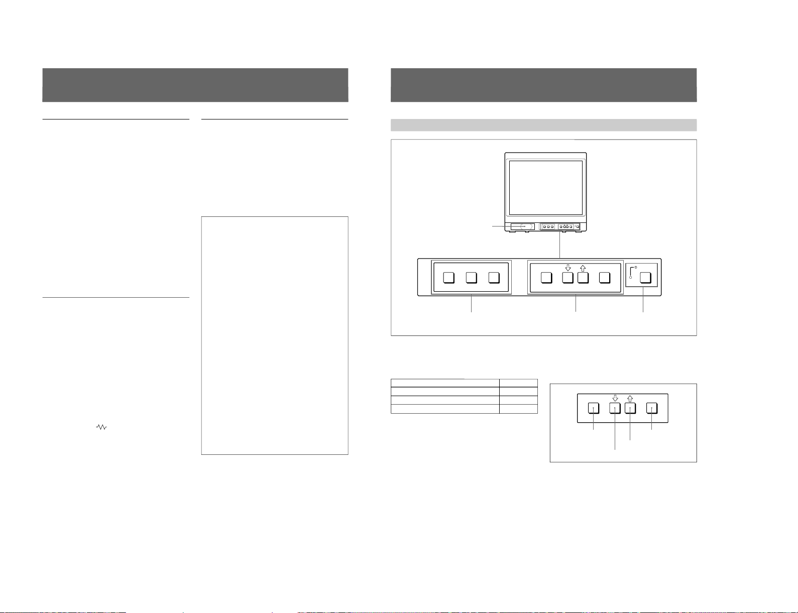
Location and Function of Parts and Controls
Front
1
Speaker
2
LINE A/LINE B/RGB buttons
3
MENU buttons
4
UPOWER
switch and
indicator
1 Speaker
2 LINE A/LINE B/RGB (input select) buttons
Press to select the program to be monitored.
Input signal
Signal fed through the LINE A connector
Signal fed through the LINE B connector
Signal fed through the RGB connectors
a)
a) Provided with the PVM-14N6A/14N6E/14N6U/20N6A/
20N6E/20N6U only.
Press
LINE A
LINE B
RGB
a)
3 MENU buttons
Press to make the menu appear.
For detailed information on MENU buttons, see “Operation
through On-Screen Menus” on page 9.
4 UPOWER switch and indicator
Press to turn the monitor on. The indicator lights in
green.
To turn the power off, press this again.
ENTER
MENU/
EXIT
MENU/EXIT button
. button
> button
ENTER button
1-3
Page 8
1-4
6
1 LINE A connectors
Input connectors for the composite video, Y/C separate
video and audio signals and their loop-through output
connectors.
To monitor the input signal fed through these
connectors, press the LINE A button on the front
panel.
Note
The Y/C IN connector has priority over the VIDEO IN
connector.
When connecting the cable to the Y/C IN connector,
the Y/C IN connector is automatically selected and the
VIDEO IN connector is disconnected even if the cable
is connected.
Y/C IN connector (4-pin mini-DIN)
Connect to the Y/C separate output connector of a
video camera, VCR or other video equipment.
Y/C OUT connector (4-pin mini-DIN)
Loop-through output of the Y/C IN connector.
Connect to the Y/C separate input connector of a VCR
or another monitor.
When the cable is connected to this connector, the 75ohm termination of the input is automatically released,
and the signal input to the Y/C IN connector is output
from this connector.
VIDEO IN connector (BNC-type)
Connect to the video output connector of video
equipment, such as a VCR or a color video camera.
For a loop-through connection, connect to the video
output connector of another monitor.
VIDEO OUT connector (BNC-type)
Loop-through output connector of the VIDEO IN
connector. Connect to the video input connector for a
VCR or another monitor.
When the cable is connected to this connector, the 75ohm termination of the input is automatically released,
and the signal input to the VIDEO IN connector is
output from this connector.
AUDIO IN connector (phono jack)
Connect to the audio output connector of a VCR or
other equipment. For a loop-through connection,
connect to the audio output of another monitor.
AUDIO OUT connector (phono jack)
Loop-through output of the AUDIO IN connector.
Connect to the audio input connector of a VCR or
another monitor.
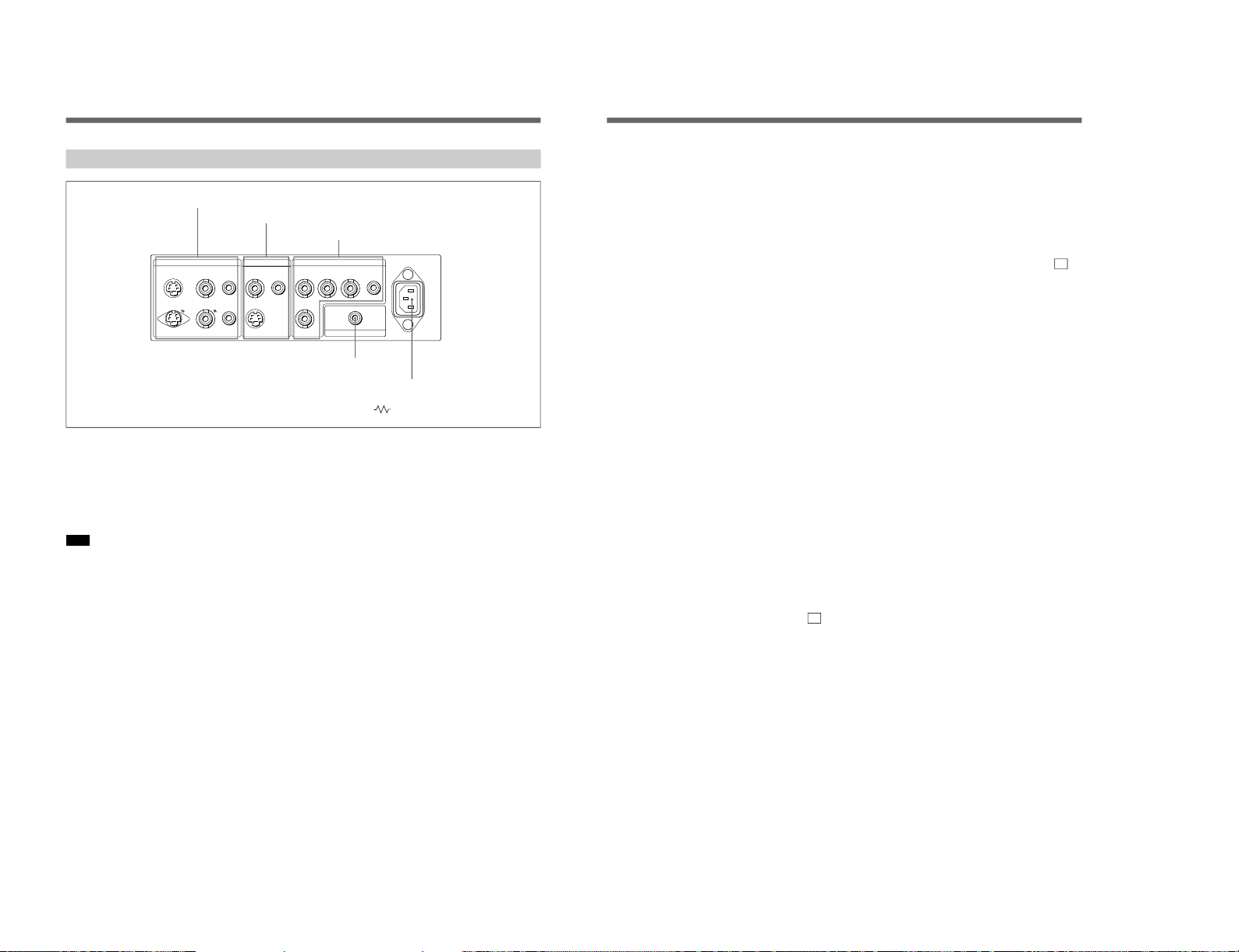
Location and Function of Parts and Controls
Rear Panel
(The mark indicates automatic termination.)
LINE BLINE A RGB ~ AC IN
Y/CINVIDEOINAUDIO
IN
OUT OUT OUT
VIDEOINAUDIO
IN
Y/C
IN
R G B AUDIO
EXT
SYNC
REMOTE
4
REMOTE connector
5
⁄AC IN connector
1
LINE A connectors
3
RGB connectors
2
LINE B connectors
7
2 LINE B connectors
Input connectors for the composite video, Y/C separate
video and audio signals.
To monitor the input signal fed through these
connectors, press the LINE B button on the front
panel.
Y/C IN connector (4-pin mini-DIN)
Connect to the Y/C separate output connector of a
video camera, VCR or other video equipment.
VIDEO IN connector (BNC-type)
Connect to the video output connector of video
equipment, such as a VCR or a color video camera.
For a loop-through connection, connect to the video
output connector of another monitor.
AUDIO IN connector (phono jack)
Connect to the audio output connector of a VCR or
other equipment. For a loop-through connection,
connect to the audio output of another monitor.
3 RGB connectors
(provided with the PVM-14N6A/14N6E/14N6U /
20N6A/20N6E/20N6U only)
Analog RGB input connectors for the R/G/B signals,
external sync signals and audio signals.
To monitor the input signal fed through these
connectors, press the RGB button on the front panel.
R/G/B (input) connectors (BNC-type)
Connect to the analog RGB outputs connectors of a
video camera, VCR or other video equipment. The
monitor operates on the external sync signal.
The monitor also can operate on the sync signal from
the G channel by setting RGB SYNC to SYNC ON
GREEN in the menu.
For detailed information on sync signal setting, see “ 3a
RGB SYNC menu ”on page 12 of “Functions of On-Screen
Menus”.
AUDIO IN connector (phono jack)
Connect to the audio output connectors of video
equipment when the analog RGB signal is input.
EXT SYNC (external sync input) connector
(BNC-type)
Connect to the sync signal output of a video camera,
VCR or other video equipment.
When you set RGB SYNC to SYNC ON GREEN in
the menu, the monitor operates on the sync signal from
the G channel so that it is not necessary to use this
connector.
For detailed information on sync signal setting, see “ 3a
RGB SYNC menu ”on page 12 of “Functions of On-Screen
Menus”.
4 REMOTE connector (phono jack)
(provided with the PVM-14N6A/14N6E/14N6U /
20N6A/20N6E/20N6U only)
This connector functions as follows.
Open: When this connector is open, the current input
signal is selected.
Ground: By grounding this connector, the input
signal selected before the current signal is selected.
5 ⁄AC IN (inlet) connector
Connect the supplied AC power cord to this connector
and to a wall outlet.
SIIA Chassis
Page 9
SIIA Chassis
8
Using On-Screen Menus
You can make various settings and adjustments of the
monitor using the on-screen menus.
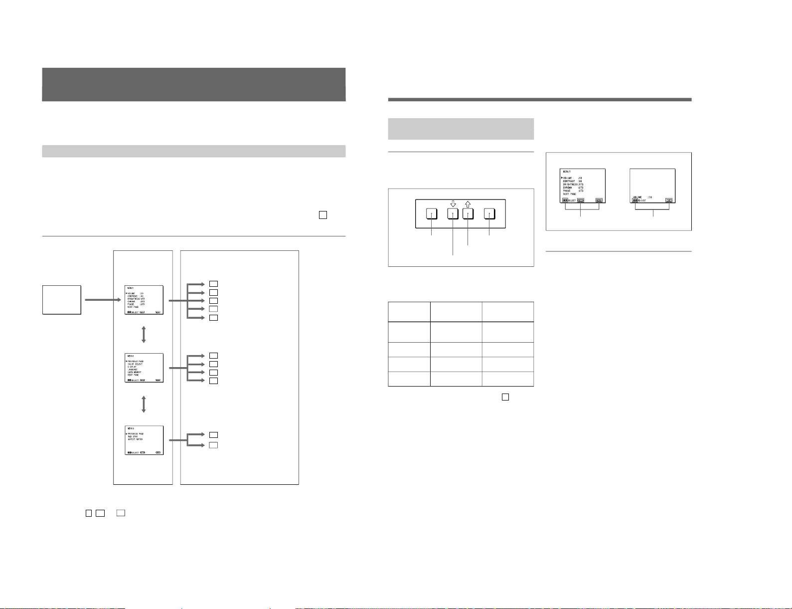
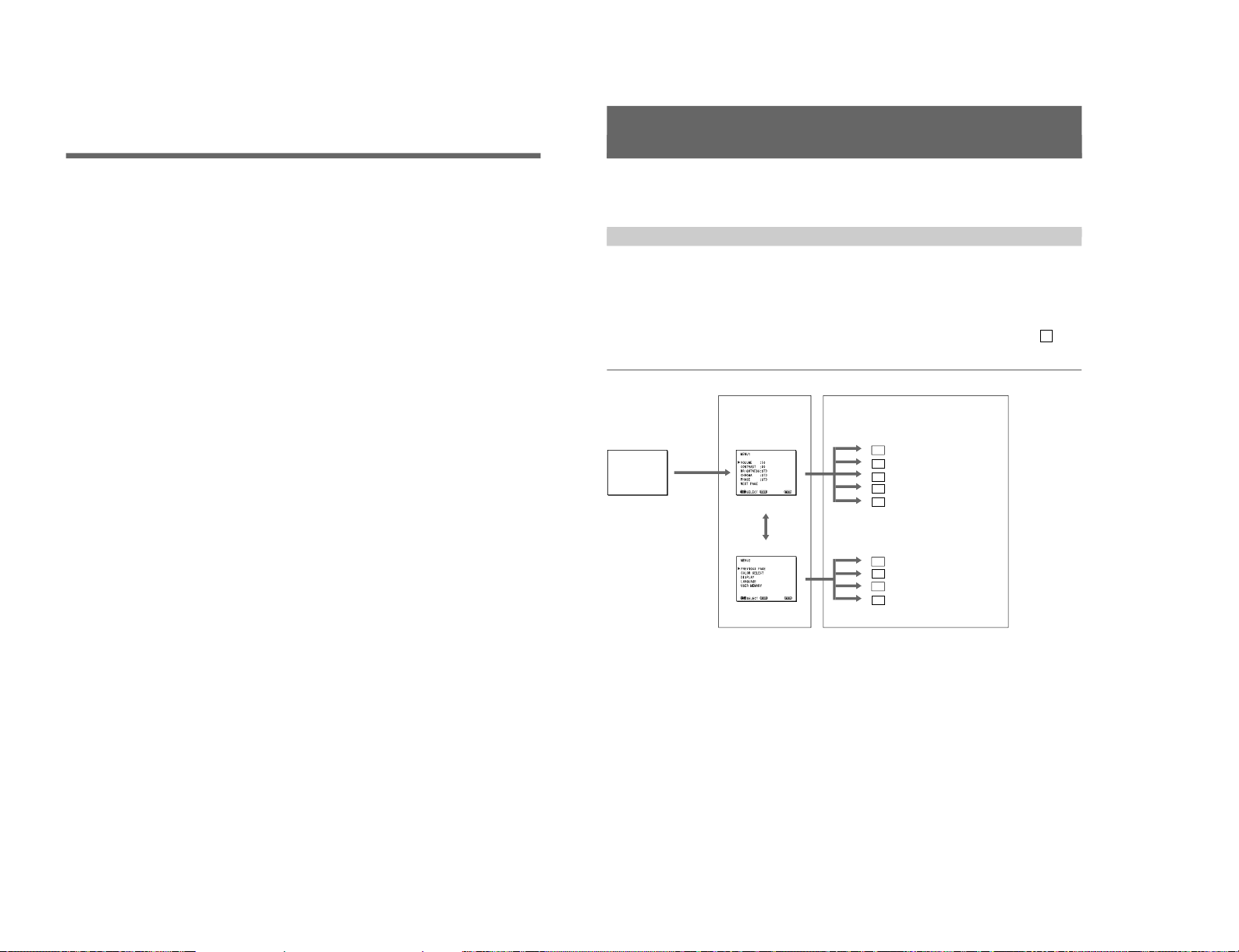
On-Screen Menu Configuration
Regular screen
1 MENU 1
On-screen menu tree-chart
2 MENU 2
3 MENU 3
a)
Item selection menus Adjustment and setting menus
a) These menus ( 3 , 3a and 3b ) are provided with PVM-14N6A/14N6E/14N6U /20N6A/20N6E/20N6U only.
Adjustment and setting menus
You can make desired adjustment or setting on
corresponding menu. The settings and adjustments
remain unchanged until next adjustment even if you
turn off the power.
To reset the settings and adjustments to the factorysettings, select “ FACTORY PRESET” from 2d USER
MEMORY menu.
The on-screen menu is composed of the following two
menu types.
Item selection menu
You can select an adjustment and setting item such as
sound volume, contrast, brightness, color intensity,
color system and menu language by using the >,. and
ENTER buttons.
1a VOLUME menu
1b CONTRAST menu
1c BRIGHTNESS menu
1d CHROMA menu
1e PHASE menu
2a COLOR SELECT menu
2b DISPLAY menu
2c LANGUAGE menu
2d USER MEMORY menu
3a RGB SYNC menu
a)
3b ASPECT RATIO menu
a)
..........................................................................................................................................................................................................
9
ENTER
MENU/
EXIT
Operation through On-Screen
Menus
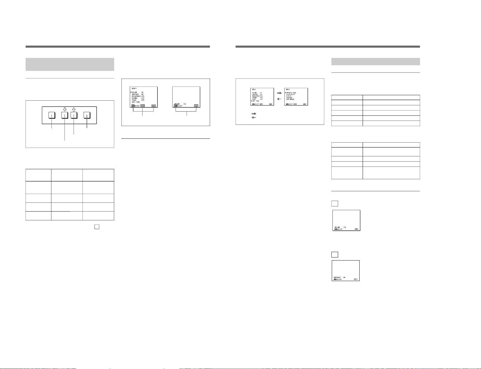
Menu operation buttons
There are four menu operation buttons on the front
panel of the monitor.
Button functions depend on the displayed menu. The
following table shows the button functions on the item
selection menus and adjustment and setting menus.
Button
1 MENU/EXIT
2 .
3 >
4 ENTER
a) You can use the ENTER button only on the 2d USER
MEMORY menu of the adjustment and setting menus.
1) 3 MENU 3 is provided with PVM-14N6A/14N6E/14N6U/20N6A/20N6E/20N6U only.
Operating procedures
To display the menu, follow this procedure.
1
Press the MENU/EXIT (1) button.
2 MENU 1 appears.
To select items other than ones not displayed on
MENU 1
Select 2 MENU 2 or 3 MENU 3
1)
.
For details of how to select, see the “To change the item
selection menus” described later.
2
Move the cursor to the desired item by pressing the
. or > (2, 3) button.
3
Press the ENTER (4) button.
The adjustment and setting menu selected in step 2
appears.
For detailed information of menus, see “Functions of OnScreen Menus” on page 10.
Usable buttons depend on the displayed menu. Buttons
that can be used on the menu are displayed at the
bottom line of the screen. You can perform menu
operation using displayed buttons.
Display of the usable menu operation buttons
Menu
Usable buttons
Usable buttons
Function on the
item selection
menus
To return to the
regular screen.
To move the cursor
downward.
To move the cursor
upward.
To decide a
selected item.
Function on the
adjustment and
setting menus
To return to the
item selection
menu.
To decrease value/
select item.
To increase value/
select item.
To decide a
selected item
a)
.
1 MENU/EXIT button
3 > button
2 . button
4 ENTER button
..........................................................................................................................................................................................................
1-5
Page 10
1-6
10
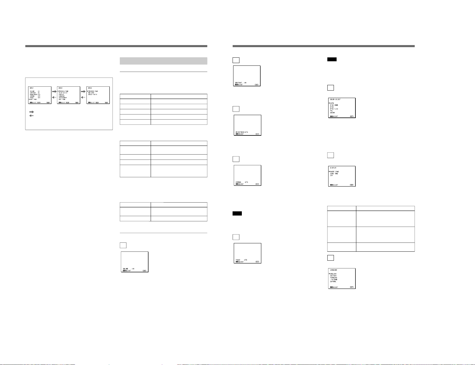
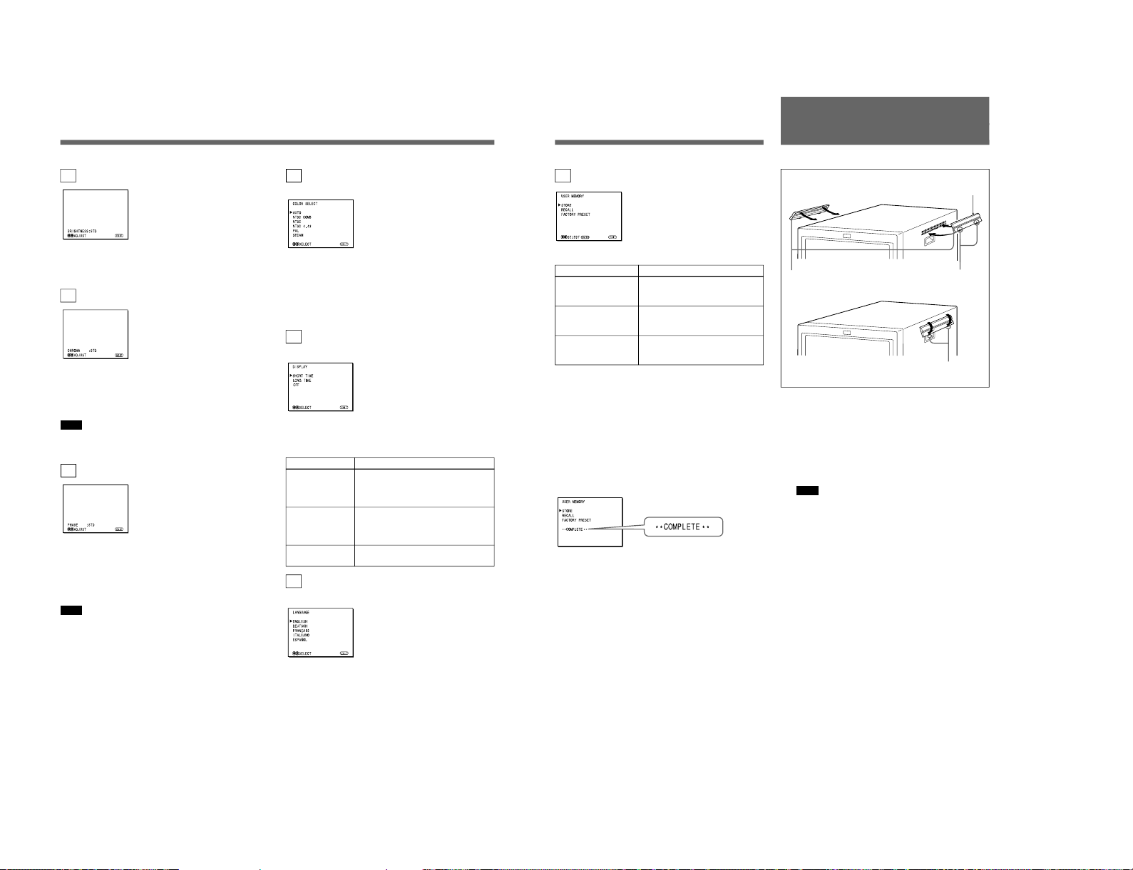
To change the item selection menus
Select NEXT PAGE on the menu to display next item
selection menu and PREVIOUS PAGE on the menu to
display the previous item selection menu.
How to change the item selection menu
To return to the item selection menu from the
adjustment and setting menus
Press the MENU/EXIT (1) button on the currently
displayed adjustment and setting menu.
To close the menu (to return to the regular
screen)
Press the MENU/EXIT (1) button when the item
selection menu is displayed. The on-screen menu
disappears and the regular screen appears.
Using the Last Control Function
If you press the > or . button when the menu is not
displayed, one of the following menu items that you
adjusted last time is displayed.
•VOLUME
•CONTRAST
•BRIGHTNESS
•CHROMA
•PHASE
Then you can adjust the item immediately.
Functions of On-Screen Menus
Item selection menus
1 MENU 1
MENU 1 menu has the following selection items.
Item
VOLUME
CONTRAST
BRIGHTNESS
CHROMA
PHASE
2 MENU 2
MENU 2 menu has the following selection items.
Item
COLOR SELECT
DISPLAY
LANGUAGE
USER MEMORY
3 MENU 3
(for PVM-14N6A/14N6E/14N6U/20N6A/
20N6E/20N6U only)
MENU 3 menu has the following selection items.
Item
RGB SYNC
ASPECT RATIO
Adjustment and setting menu
1a VOLUME menu (Factory setting: 50)
Adjust the speaker volume.
The volume increases by pressing the > button.
The volume decreases by pressing . button.
Using On-Screen Menus
:
:
MENU 1 MENU 2 MENU 3
a)
When selecting NEXT PAGE
When selecting PREVIOUS PAGE
a) MENU 3 is provided with PVM-14N6A/14N6E/14N6U/
20N6A/20N6E/20N6U only.
Functions
To obtain the desired volume
To adjust the contrast
To adjust the brightness
To adjust the color intensity
To adjust the phase
Function
To select the color system of the
input signal
To select period of display
To select the menu language
To store and recall the values and
settings adjusted by a user, and recall
the factory-settings
Function
To select the sync signal when the
RGB signals are input
To select the aspect ratio
11
1b CONTRAST menu (Factory setting: 80)
Adjust the contrast of the screen.
The contrast becomes higher by pressing the > button.
The contrast becomes lower by pressing . button.
1c BRIGHTNESS menu (Factory setting: STD)
Adjust the brightness of the screen.
The screen becomes brighter by pressing the > button.
The screen becomes darker by pressing . button.
1d CHROMA menu (Factory setting: STD)
Adjust the color intensity of the video signal.
The color intensity strengthens by pressing the >
button.
The color intensity weakens by pressing . button.
Note
The color intensity of an composite video signal or a
Y/C separate signal can be corrected on this menu.
That of the RGB signals cannot be corrected.
1e PHASE menu (Factory setting: STD)
Adjust the phase of the video signals.
The skin tone becomes greenish by pressing the >
button.
The skin tone becomes purplish by pressing the .
button.
Note
The phase of an NTSC composite video signal or a
Y/C separate signal can be corrected on this menu. The
PAL composite video signal or a Y/C separate signal
and RGB signals cannot be corrected.
2a COLOR SELECT menu
(Factory setting: AUTO)
Select the color system of the input signal.
AUTO: Input color systems are automatically
selected.
When you input NTSC signal, comb filter will
activate. To monitor NTSC signal with trap filter,
select NTSC in this menu.
2b DISPLAY menu
(Factory setting: SHORT TIME)
Select the period of displaying the color system of the
current input signals.
The items have the following functions.
Item
SHORT TIME
LONG TIME
OFF
2c LANGUAGE menu
(Factory setting: ENGLISH)
Select the menu language among the five languages,
English, German, French, Italian and Spanish.
Function
To display the kind of color system
being used for several seconds on the
screen each time you change the
signal input.
To display the kind of color system
being used for approximately five
minutes on the screen each time you
change the signal input.
Not to display the kind of the color
system.
SIIA Chassis
Page 11
SIIA Chassis
12
The following menus are provided with the PVM14N6A/14N6E/14N6U /20N6A/20N6E/20N6U only.
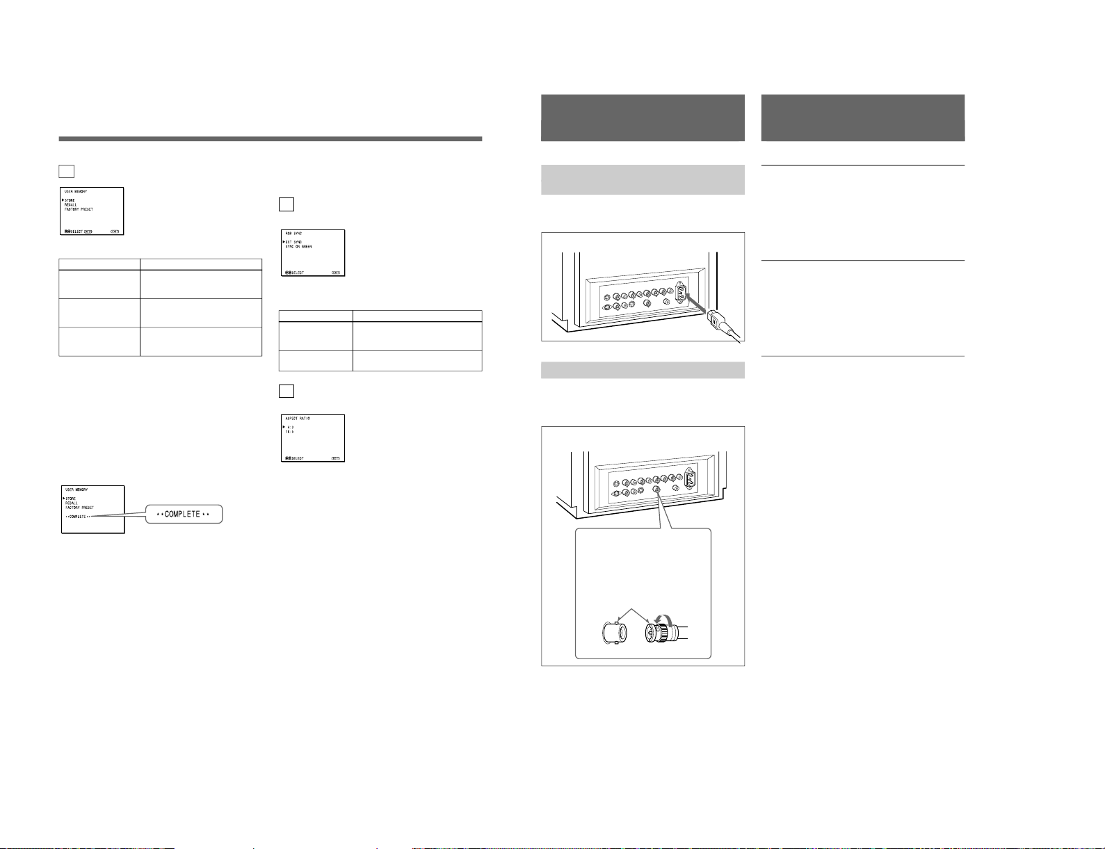
3a RGB SYNC menu
(Factory setting: EXT SYNC)
Select the sync signal when the RGB signals are input.
The items have the following functions.
Item
EXT SYNC
SYNC ON GREEN
3b ASPECT RATIO menu
(Factory setting: 4:3)
Select the aspect ratio of the screen.
2d USER MEMORY menu
The items have the following functions.
Item
STORE
RECALL
FACTORY PRESET
a) The current settings and adjusted values are reset to the
factory settings. The values and settings adjusted and
stored in the internal memory by using the STORE
menu, however, are not changed. To reset internally
stored adjusted values and settings to the factory setting,
select FACTORY PRESET, first, then select STORE.
When you press the ENTER (4) button, the following
message is displayed for about two seconds. The
currently selected item becomes active when pressing
the ENTER (4) button.
Using On-Screen Menus
Function
To store all adjustments and
settings currently set on each
menu into the internal memory.
To recall all adjustments and
settings currently stored in the
internal memory.
To reset the adjustments and
settings currently set on each
menu to the factory settings.
a)
Function
To operate the monitor on an
external sync signal fed through the
RGB SYNC connector.
To operate the monitor on the sync
signal from the G channel.
13
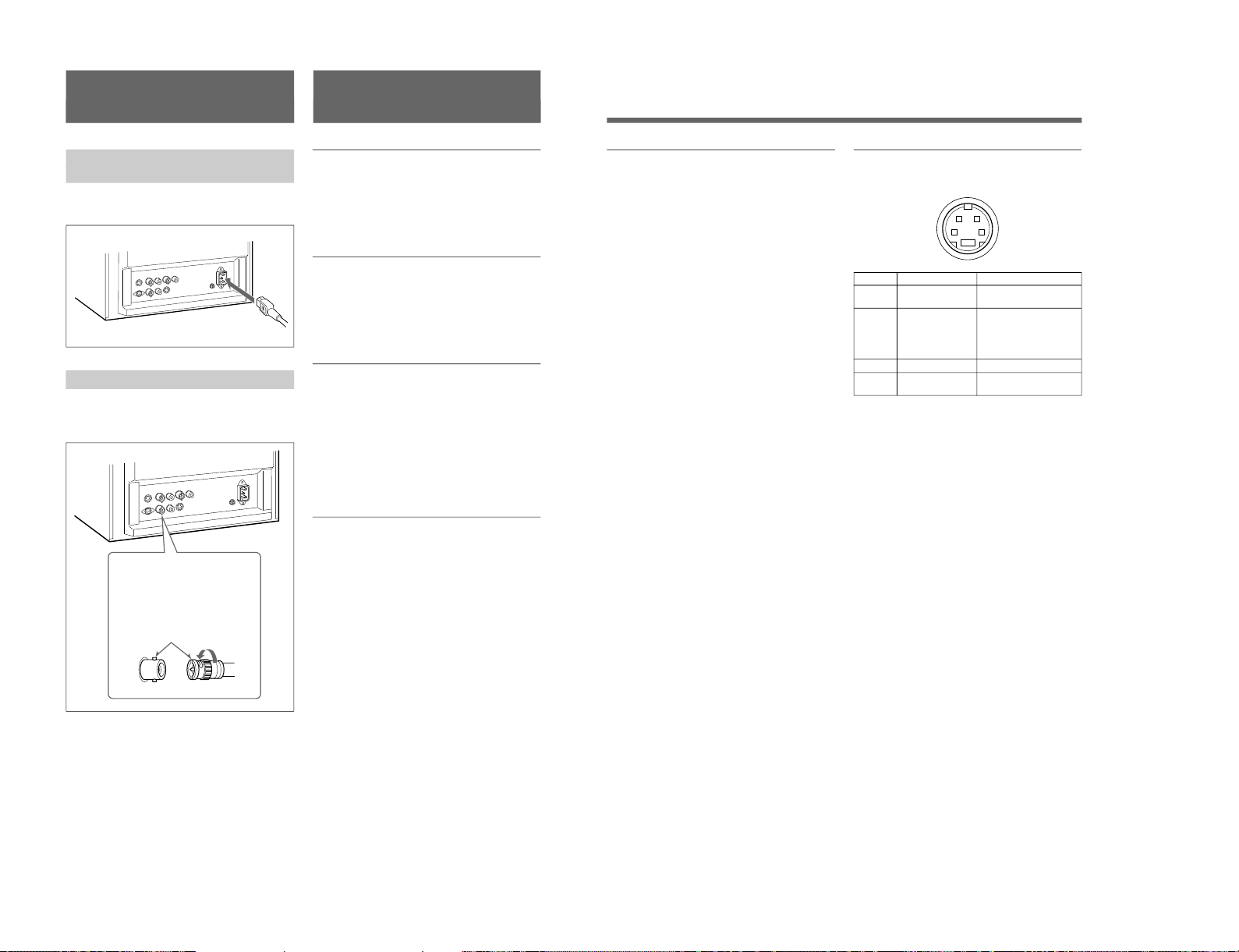
Connections
How to Connect the AC Power
Cord
Connect the AC power cord (supplied) to the ⁄AC IN
connector and to a wall outlet.
How to Connect a Cable to a BNC Connector
Connect the coaxial cable with the BNC connectors to
the BNC connectors on the rear panel as illustrated
below.
Video signal
Color system NTSC, PAL, SECAM, NTSC
4.43
Resolution 500 TV lines
Frequency response
LINE 6 MHz±3dB (Y signal)
RGB 6 MHz±3dB
Picture performance
Normal scan 7 % over scan of CRT effective
screen area
H. linearity Less than 8.0 % (typical)
V. linearity Less than 7.0 % (typical)
Color temperature D65
Inputs
LINE A/B
Y/C IN 4-pin mini-DIN(×2)
See the pin assignment on the next page.
VIDEO IN BNC connector (×2), 1Vp-p +3 dB,
–6 dB, sync negative
AUDIO IN Phono jack (×2), –5 dBu
a)
, more
than 47 kilo-ohms
RGB (PVM-14N6A/14N6E/14N6U/20N6A/20N6E/
20N6U only)
R/G/B BNC connector (×3)
0.7 Vp-p +3 dB, –6 dB
Sync on green: 0.3 Vp-p, negative
AUDIO IN Phono jack (×1), –5 dBu
a)
, more
than 47 kilo-ohms
EXT SYNC BNC connector (×1)
4 Vp-p +3 dB, –6 dB, sync
negative
REMOTE (PVM-14N6A/14N6E/14N6U/20N6A/
20N6E/20N6U only)
Phono jack (×1)
Open: currently selected input
signal
Low state (GND): input signal
selected prior to the current input
signal
a) 0 dBu = 0.775 Vr.m.s.
Insert the connector into the BNC
connector on the rear panel,
matching the slit and pin, and turn
the cable BNC connector clockwise
to secure the BNC connector of a
coaxial cable.
Specifications
1-7
Page 12
1-8
14
Specifications
Outputs
LINE A
Y/C OUT 4-pin mini-DIN (×1) loop-through,
Automatic 75 ohms termination
VIDEO OUT
BNC connector (×1) loop-through,
Automatic 75 ohms termination
AUDIO OUT
Phono jack (×1) loop-through
Speaker output Output level: 0.8 W
General
CRT PVM-14N5A/14N5E/14N5U/
14N6A/14N6E/14N6U:
14-inch CRT with P-22 phosphor
Visible picture size 340 mm
(13-inch measured diagonally)
PVM-20N5A/20N5E/20N5U/
20N6A/20N6E/20N6U:
20-inch CRT with P-22 phosphor
Visible picture size 490 mm
(19-inch measured diagonally)
Power consumption
PVM-14N5A/14N5E/14N5U: 80W
PVM-14N6A/14N6E/14N6U: 80W
PVM-20N5U/20N6U: 100W
PVM-20N5A/20N6A/20N5E/
20N6E: 105 W
Power requirements
100 to 240 V AC, 50/60Hz
“For use of PVM-14N5U/14N6U/
20N5U/20N6U”, operate these
monitors on 120 V AC.
Operating conditions
Temperature 0 to +35°C
Humidity 0 to 90% (no condensation)
Transport and Storage conditions
Temperature –10 to +40°C
Humidity 0 to 90%
Dimensions (w/h/d)
PVM-14N5A/14N5E/14N5U/
14N6A/14N6E/14N6U:
346 × 340 × 414 mm
(13
5
⁄8 × 131⁄2 × 163⁄8 inches)
PVM-20N5A/20N5E/20N5U/
20N6A/20N6E/20N6U:
449 × 441 × 502 mm
(17
3
⁄4 × 173⁄8 × 197⁄8 inches)
Mass PVM-14N5A/14N5E/14N5U/
14N6A/14N6E/14N6U:
Approx. 15 kg (33 lb 1 oz)
PVM-20N5A/20N5E/20N5U/
20N6A/20N6E/20N6U:
Approx. 28 kg (61 lb 12 oz)
Accesory supplied AC power cord (1)
Operating Instructions (1)
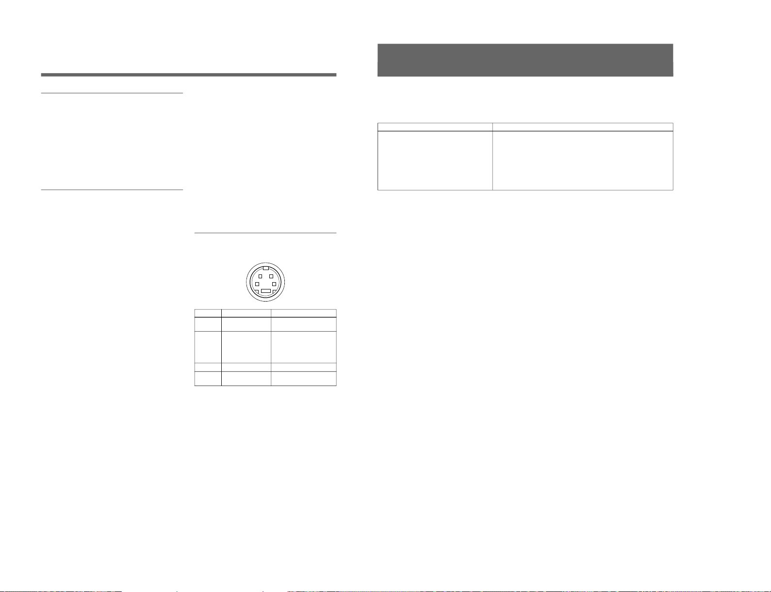
Pin assignment
Y/C IN connector (4-pin mini-DIN)
21
34
*
Pin No.
1
2
3
4
Design and specifications are subject to change
without notice.
Signal
Y-input
CHROMA
subcarrier-input
GND for Y-input
GND for CHROMA-
input
Description
1 Vp-p, sync negative, 75
ohms
0.286 Vp-p (NTSC), 300m
Vp-p (PAL), burst
Delay time between Y and
C: within 0 ± 100 nsec.,
75 ohms
GND
GND
15
This section may help you isolate the problem. Should
the problem persist, unplug the unit and contact your
Sony dealer or local authorized Sony service facility.
Troubleshooting
Symptom
If colors are not accurately reproduced
Possible causes and remedies
The monitor input signal is deviated from the color system specifications (i.e.
signals from VCRs).
Proceed as follows to correct this phenomenon.
1
Confirm the color system of the input signal.
2
Select the same color system as that of the input signal on the COLOR
SELECT menu.
If the problem remains unsolved after corresponding color system is
selected, briefly turn OFF the power, then turn ON the monitor again.
SIIA Chassis
Page 13
SIIA Chassis
Trinitron
®
Color Video Monitor
3-864-165-11(2)
PVM-14N5MDE
Instructions for Use
Page 2
Mode d’emploi
Page 18
Gebrauchsanweisung
Seite 34
Instrucciones de uso
Página 50
Istruzioni per l’uso
Pagina 66
######
82
EN
F
D
1998 by Sony Corporation
E
I
C
8
1-2. PVM-14N5MDE
1-9
Page 14

1-10
2
English
Owner’s Recor d
The model and serial numbers are located at the rear.
Record these numbers in the spaces provided below.
Refer to these numbers whenever you call upon your
Sony dealer regarding this product.
Model No.
Serial No.
WARNING
To prevent fire or shock hazard, do not
expose the unit to rain or moisture.
Dangerously high voltage are present
inside the unit.
Do not open the cabinet. Refer servicing
to qualified personnel only.
In the event of a malfunction or when maintenance is
necessary, consult an authorized Sony dealer.
Power Switch
The power switch is a functional switch only. To isolate
the set from the mains supply remove the mains plug
from the wall socket.
For the customers in the U.S.A.
This equipment has been tested and found to comply with
the limits for a Class A digital device, pursuant to Part 15 of
the FCC Rules. These limits are designed to provide
reasonable protection against harmful interference when the
equipment is operated in a commercial environment.
This equipment generates, uses, and can radiate radio
frequency energy and, if not installed and used in
accordance with the instruction manual, may cause harmful
interference to radio communications. Operation of this
equipment in a residential area is likely to cause harmful
interference in which case the user will be required to correct
the interference at his own expense.
You are cautioned that any changes or modifications not
expressly approved in this manual could void your authority
to operate this equipment.
For the customers in the United Kingdom
WARNING
THIS APPARATUS MUST BE EARTHED
IMPORTANT
The wires in this mains lead are coloured in accordance with
the following code:
Green-and-yellow: Earth
Blue: Neutral
Brown: Live
As the colours of the wires in the mains lead of this
apparatus may not correspond with the coloured markings
identifying the terminals in your plug proceed as follows:
The wire which is coloured green-and-yellow must be
connected to the terminal in the plug which is marked by the
letter E or by the safety earth symbol Y or coloured green or
green-and-yellow.
The wire which is coloured blue must be connected to the
terminal which is marked with the letter N or coloured black.
The wire which is coloured brown must be connected to the
terminal which is marked with the letter L or coloured red.
Ensure that your equipment is connected correctly - If you
are in any doubt consult a qualified electrician.
This unit contains substances which can pollute the
environment if disposed carelessly. Please contact our
nearest office or your local environmental office in case of
disposal of this unit.
ATTENTION:
Picture distortion may occur if this monitor is positioned
in close proximity to any equipment emitting
electromagnetic radiation.
3
Table of Contents
Precaution
On safety
•Operate the unit only with a power source as
specified in “Specifications” section.
•The nameplate indicating operating voltage, power
consumption, etc., is located at the rear.
•Should any solid object or liquid fall into the cabinet,
unplug the unit and have it checked by qualified
personnel before operating it any further.
•Do not drop or place heavy objects on the power
cord. If the power cord is damaged, turn off the
power immediately. It is dangerous to use the unit
with a damaged power cord.
•Unplug the unit from the wall outlet if it is not to be
used for several days or more.
•Disconnect the power cord from the AC outlet by
grasping the plug, not by pulling the cord.
•The socket-outlet shall be installed near the
equipment and shall be easily accessible.
On installation
•Allow adequate air circulation to prevent internal heat
build-up.
Do not place the unit on surfaces (rugs, blankets, etc.)
or near materials (curtains, draperies) that may block
the ventilation holes.
•Do not install the unit in a location near heat sources
such as radiators or air ducts, or in a place subject to
direct sunlight, excessive dust, mechanical vibration
or shock.
On cleaning
To keep the unit looking brand-new, periodically clean
it with a mild detergent solution. Never use strong
solvents such as thinner or benzine, or abrasive
cleansers since they will damage the cabinet. As a
safety precaution, unplug the unit before cleaning it.
On repacking
Do not throw away the carton and packing materials.
They make an ideal container to transport the unit.
If you have any questions about this unit, contact your
authorized Sony dealer.
About this manual
Before operating the unit, please read this manual
thoroughly and retain it for future reference.
Attention – when the product is installed in a rack:
•Elevated operating ambient temperature
If installed in a closed or multi-unit rack
assembly, the operating ambient temperature of
the rack environment may be greater than room
ambient.
Therefore, consideration should be given to
installing the equipment in an environment
compatible with the manufacturer’s maximum
rated ambient temperature of 0 to +40 ºC (Tmra).
•Reduced air flow
Installation of the equipment in a rack should be
such that the amount of air flow required for safe
operation of the equipment is not compromised.
•Mechanical loading
Mounting of the equipment in the rack should be
such that a hazardous condition is not achieved
due to uneven mechanical loading.
•Circuit overloading
Consideration should be given to the connection
of the equipment to the supply circuit and the
effect that overloading of circuits might have on
overcurrent protection and supply wiring.
Appropriate consideration of equipment
nameplate ratings should be used when
addressing this concern.
•Reliable earthing
Reliable earthing of rack-mounted equipment
should be maintained. Particular attention should
be given to supply connections other than direct
connections to the branch circuit (e.g., use of
power strips).
Features ............................................................ 5
Location and Function of Parts and Controls 6
Front .................................................................... 6
Rear Panel ........................................................... 7
Using On-Screen Menus.................................. 9
On-Screen Menu Configuration .......................... 9
Operation through On-Screen Menus ............... 10
Functions of On-Screen Menus......................... 11
Attaching the Side Covers ............................ 13
Connections ................................................... 14
How to Connect the AC Power Cord ................ 14
How to Connect a Cable to a BNC Connector.. 14
Specifications................................................. 14
Troubleshooting............................................. 16
SIIA Chassis
Page 15
SIIA Chassis
4
Be sure to connect the AC power cord to a
grounded outlet.
Important safeguards/notices for use in the
medical environments
1
All the equipments connected to this unit shall be
certified according to Standard IEC601-1, IEC950,
IEC65 or other IEC/ISO Standards applicable to
the equipments.
2
When this unit is used together with other
equipment in the patient area*, the equipment shall
be either powered by an isolation transformer or
connected via an additional protective earth
terminal to system ground unless it is certified
according to Standard IEC601-1 and IEC601-1-1.
* Patient Area
3
The leakage current could increase when
connected to other equipment.
4
The operator should take precautions to avoid
touching the rear panel input and output circuitry
and the patient at the same time.
5
Model PVM-14N5MDE is a video monitor
intended for use in a medical environment to
display video pictures from cameras or other video
system.
R1.5m
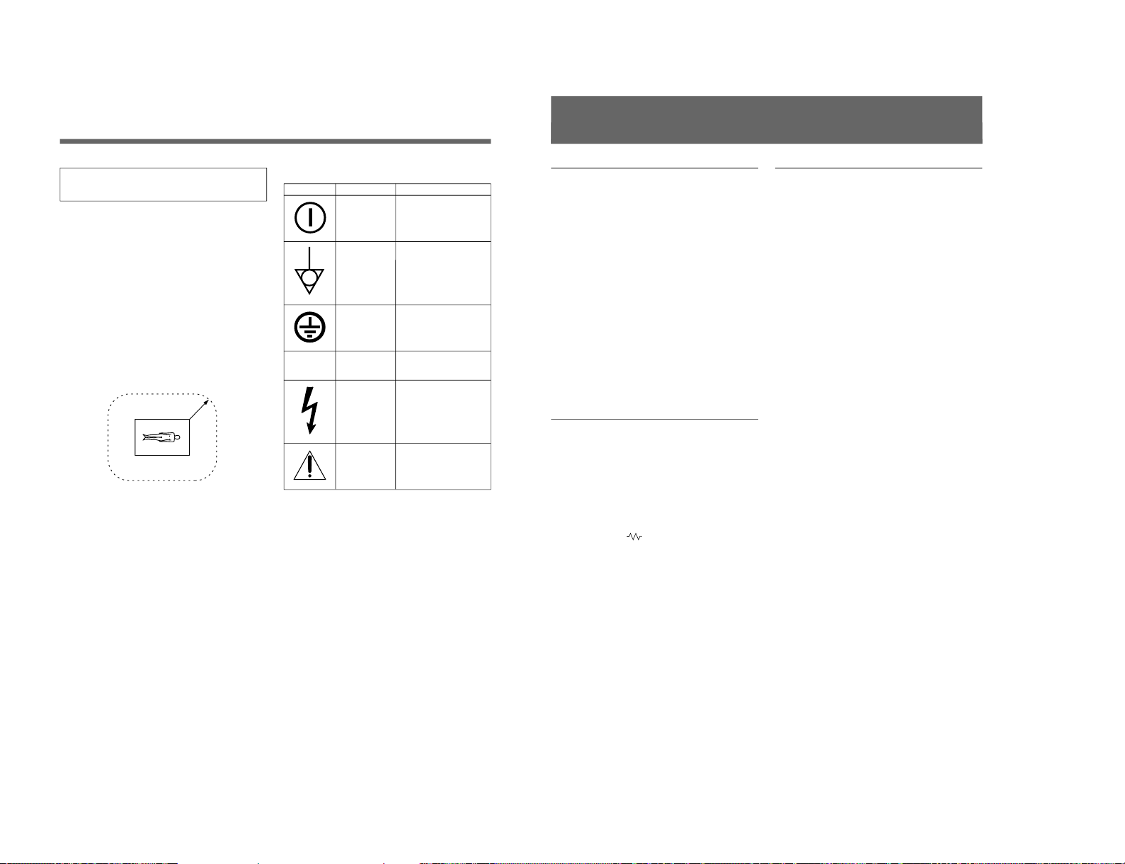
Symbols on the unit
Symbol
Location
Front panel
Rear panel
Inside the unit
Rear panel
Inside the unit
Rear panel
This symbol indicates
Main power switch.
Press to turn the monitor
on or off.
The equipotential terminal
which brings the various
parts of a system to the
same potential.
Protective earth
Alternating current
Presence of uninsulated
“dangerous voltage” within
the product’s enclosure
that may be sufficient to
constitute a risk of electric
shock.
Attention, consult
ACCOMPANYING
DOCUMENTS
⁄
5
Picture
Fine pitch Trinitron
1)
picture tube
The fine pitch Trinitron tube provides a high resolution
picture. Horizontal resolution is more than 500 TV
lines at the center of the picture.
Comb filter
When NTSC video signals are received, a comb filter
activates to make more accurate Y/C separation. This
contributes to less of a decrease in resolution, cross
color and cross luminance phenomena.
Beam current feedback circuit
The built-in beam current feedback circuit assures
stable white balance.
Four color system available
The monitor can display NTSC, PAL, SECAM and
NTSC
4.43
2)
signals. The appropriate color system is
selected automatically.
Input
Y/C input connectors
The video signal, split into the chrominance signal (C)
and the luminance signal (Y), can be input through this
connector, eliminating the interference between the
two signals, which tends to occur in a composite video
signal, ensuring video quality.
Automatic termination
(connector with
mark only)
The input connector is terminated at 75 ohms inside
when no cable is connected to the loop-through output
connector. When a cable is connected to an output
connector, the 75-ohm termination is automatically
released.
Features
Functions
On-screen menus
You can set monitor operation settings by using the
on-screen menus.
EIA standard 19-inch rack mounting
By using an MB-502B mounting bracket (not
supplied), the monitor can be mounted in an EIA
standard 19-inch rack.
For details on mounting, refer to the instruction manuals
supplied with the mounting bracket kit.
Side covers
The monitor can be covered with side covers. The side
covers that protect the ventilation holes from splashes
(of medicines, etc.) as much as possible.
1) Trinitron
“Trinitron” is a registered trademark of Sony Corporation.
2) NTSC
4.43
The NTSC
4.43
system refers to an NTSC color system in which the subcarrier frequency is modified to 4.43MHz. When an
NTSC recorded video program is played back with a Trident (PAL/SECAM/NTSC
4.43
) VTR, the NTSC
4.43
signal is output.
..........................................................................................................................................................................................................
1-11
Page 16
1-12
6
LINE A LINE B ENTER
MENU/
EXIT
POWER
LINE A LINE B ENTER
MENU/
EXIT
POWER
ENTER
MENU/
EXIT
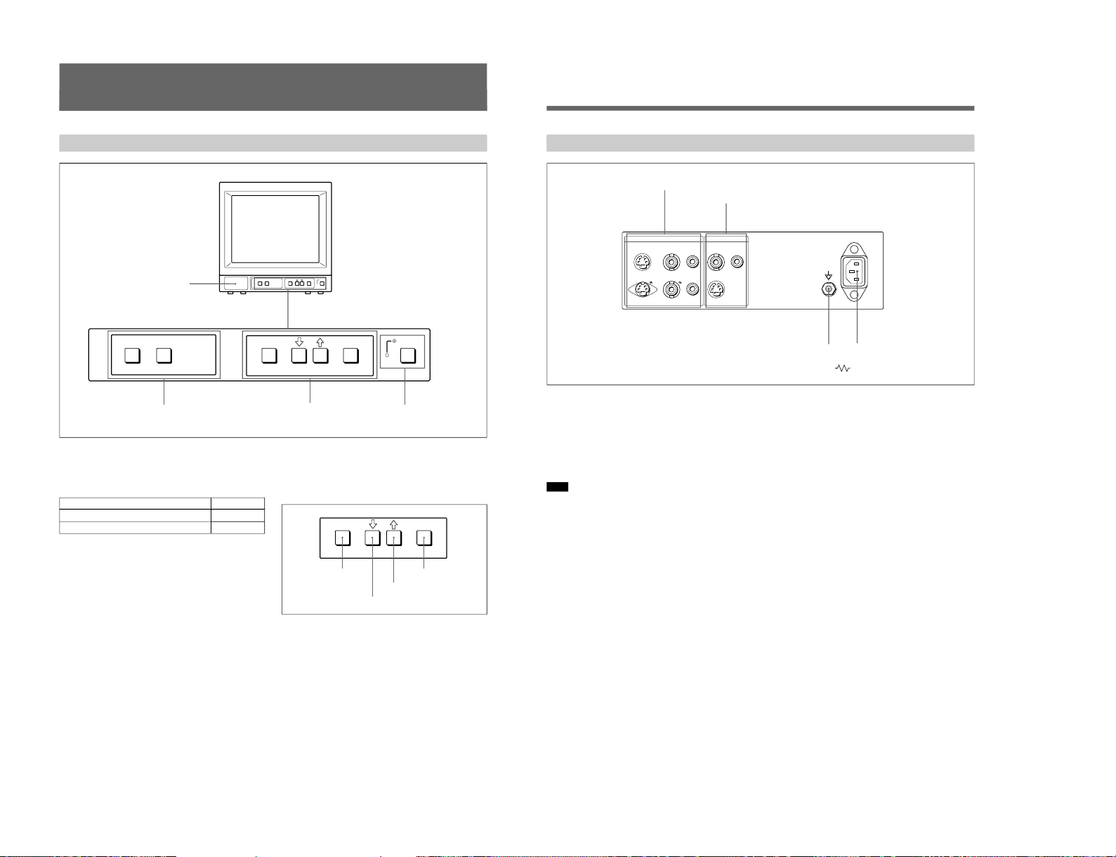
Location and Function of Parts and Controls
ENTER button
Front
2
LINE A/LINE B buttons
3
MENU buttons
4
UPOWER switch
and indicator
1 Speaker
2 LINE A/LINE B (input select) buttons
Press to select the program to be monitored.
Input signal
Signal fed through the LINE A connector
Signal fed through the LINE B connector
Press
LINE A
LINE B
3 MENU buttons
Press to make the menu appear.
For detailed information on MENU buttons, see “Operation
through On-Screen Menus” on page 10.
4 UPOWER switch and indicator
Press to turn the monitor on. The indicator lights in
green.
To turn the power off, press this again.
MENU/EXIT button
. button
> button
1
Speaker
7
1 LINE A connectors
Input connectors for the composite video, Y/C separate
video and audio signals and their loop-through output
connectors.
To monitor the input signal fed through these
connectors, press the LINE A button on the front
panel.
Note
The Y/C IN connector has priority over the VIDEO IN
connector.
When connecting the cable to the Y/C IN connector,
the Y/C IN connector is automatically selected and the
VIDEO IN connector is disconnected even if the cable
is connected.
Y/C IN connector (4-pin mini-DIN)
Connect to the Y/C separate output connector of a
video camera, VCR or other video equipment.
Y/C OUT connector (4-pin mini-DIN)
Loop-through output of the Y/C IN connector.
Connect to the Y/C separate input connector of a VCR
or another monitor.
When the cable is connected to this connector, the 75ohm termination of the input is automatically released,
and the signal input to the Y/C IN connector is output
from this connector.
VIDEO IN connector (BNC-type)
Connect to the video output connector of video
equipment, such as a VCR or a color video camera.
For a loop-through connection, connect to the video
output connector of another monitor.
VIDEO OUT connector (BNC-type)
Loop-through output connector of the VIDEO IN
connector. Connect to the video input connector for a
VCR or another monitor.
When the cable is connected to this connector, the 75ohm termination of the input is automatically released,
and the signal input to the VIDEO IN connector is
output from this connector.
AUDIO IN connector (phono jack)
Connect to the audio output connector of a VCR or
other equipment. For a loop-through connection,
connect to the audio output of another monitor.
AUDIO OUT connector (phono jack)
Loop-through output of the AUDIO IN connector.
Connect to the audio input connector of a VCR or
another monitor.
Rear Panel
LINE BLINE A ~ AC IN
Y/CINVIDEOINAUDIO
IN
OUT OUT OUT
VIDEOINAUDIO
IN
Y/C
IN
(The mark indicates automatic termination.)
1
LINE A connectors
2
LINE B connectors
4
⁄AC IN connector
3
Ground terminal
SIIA Chassis
Page 17
SIIA Chassis
8
2 LINE B connectors
Input connectors for the composite video, Y/C separate
video and audio signals.
To monitor the input signal fed through these
connectors, press the LINE B button on the front
panel.
Y/C IN connector (4-pin mini-DIN)
Connect to the Y/C separate output connector of a
video camera, VCR or other video equipment.
VIDEO IN connector (BNC-type)
Connect to the video output connector of video
equipment, such as a VCR or a color video camera.
For a loop-through connection, connect to the video
output connector of another monitor.
AUDIO IN connector (phono jack)
Connect to the audio output connector of a VCR or
other equipment. For a loop-through connection,
connect to the audio output of another monitor.
3 Ground (1) terminal
Connect a GND cable.
4 ⁄AC IN (inlet) connector
Connect the supplied AC power cord to this connector
and to a wall outlet.
Location and Function of Parts and Controls
9
Using On-Screen Menus
You can make various settings and adjustments of the
monitor using the on-screen menus.
Regular screen
1 MENU 1
1a VOLUME menu
1b CONTRAST menu
1c BRIGHTNESS menu
1d CHROMA menu
1e PHASE menu
2a COLOR SELECT menu
2c LANGUAGE menu
2b DISPLAY menu
On-screen menu tree-chart
2 MENU 2
Item selection menus Adjustment and setting menus
2d USER MEMORY menu
Adjustment and setting menus
You can make desired adjustment or setting on
corresponding menu. The settings and adjustments
remain unchanged until next adjustment even if you
turn off the power.
To reset the settings and adjustments to the factorysettings, select “ FACTORY PRESET” from 2d USER
MEMORY menu.
The on-screen menu is composed of the following two
menu types.
Item selection menu
You can select an adjustment and setting item such as
sound volume, contrast, brightness, color intensity,
color system and menu language by using the >,. and
ENTER buttons.
On-Screen Menu Configuration
1-13
Page 18
1-14
10
ENTER
MENU/
EXIT
Operation through On-Screen
Menus
Menu operation buttons
There are four menu operation buttons on the front
panel of the monitor.
Button functions depend on the displayed menu. The
following table shows the button functions on the item
selection menus and adjustment and setting menus.
Button
1 MENU/EXIT
2 .
3 >
4 ENTER
a) You can use the ENTER button only on the 2d USER
MEMORY menu of the adjustment and setting menus.
1 MENU/EXIT button
3 > button
2 . button
4 ENTER button
Function on the
item selection
menus
To return to the
regular screen.
To move the cursor
downward.
To move the cursor
upward.
To decide a
selected item.
Function on the
adjustment and
setting menus
To return to the
item selection
menu.
To decrease value/
select item.
To increase value/
select item.
To decide a
selected item
a)
.
Operating procedures
To display the menu, follow this procedure.
1
Press the MENU/EXIT (1) button.
1 MENU 1 appears.
To select items other than ones not displayed on
MENU 1
Select 2 MENU 2.
For details of how to select, see the “To change the item
selection menus” described later.
2
Move the cursor to the desired item by pressing the
. or > (2, 3) button.
3
Press the ENTER (4) button.
The adjustment and setting menu selected in step 2
appears.
For detailed information of menus, see “Functions of OnScreen Menus” on page 11.
Usable buttons depend on the displayed menu. Buttons
that can be used on the menu are displayed at the
bottom line of the screen. You can perform menu
operation using displayed buttons.
Display of the usable menu operation buttons
Menu
Usable buttons
Usable buttons
Using On-Screen Menus
11
To change the item selection menus
Select NEXT PAGE on the menu to display next item
selection menu and PREVIOUS PAGE on the menu to
display the previous item selection menu.
How to change the item selection menu
To return to the item selection menu from the
adjustment and setting menus
Press the MENU/EXIT (1) button on the currently
displayed adjustment and setting menu.
To close the menu (to return to the regular
screen)
Press the MENU/EXIT (1) button when the item
selection menu is displayed. The on-screen menu
disappears and the regular screen appears.
:
:
MENU 1 MENU 2
When selecting NEXT PAGE
When selecting PREVIOUS PAGE
Functions of On-Screen Menus
Item selection menus
1 MENU 1
MENU 1 menu has the following selection items.
Item
VOLUME
CONTRAST
BRIGHTNESS
CHROMA
PHASE
2 MENU 2
MENU 2 menu has the following selection items.
Item
COLOR SELECT
DISPLAY
LANGUAGE
USER MEMORY
Adjustment and setting menu
1a VOLUME menu (Factory setting: 50)
Adjust the speaker volume.
The volume increases by pressing the > button.
The volume decreases by pressing . button.
1b CONTRAST menu (Factory setting: 80)
Adjust the contrast of the screen.
The contrast becomes higher by pressing the > button.
The contrast becomes lower by pressing . button.
Functions
To obtain the desired volume
To adjust the contrast
To adjust the brightness
To adjust the color intensity
To adjust the phase
Function
To select the color system of the
input signal
To select period of display
To select the menu language
To store and recall the values and
settings adjusted by a user, and recall
the factory-settings
SIIA Chassis
Page 19
SIIA Chassis
12
Using On-Screen Menus
1c BRIGHTNESS menu (Factory setting: STD)
Adjust the brightness of the screen.
The screen becomes brighter by pressing the > button.
The screen becomes darker by pressing . button.
1d CHROMA menu (Factory setting: STD)
Adjust the color intensity of the video signal.
The color intensity strengthens by pressing the >
button.
The color intensity weakens by pressing . button.
Note
The color intensity of an composite video signal or a
Y/C separate signal can be corrected on this menu.
1e PHASE menu (Factory setting: STD)
Adjust the phase of the video signals.
The skin tone becomes greenish by pressing the >
button.
The skin tone becomes purplish by pressing the .
button.
Note
The phase of an NTSC composite video signal or a
Y/C separate signal can be corrected on this menu. The
PAL composite video signal or a Y/C separate signal
cannot be corrected.
2a COLOR SELECT menu
(Factory setting: AUTO)
Select the color system of the input signal.
AUTO: Input color systems are automatically
selected.
When you input NTSC signal, comb filter will
activate. To monitor NTSC signal with trap filter,
select NTSC in this menu.
2b DISPLAY menu
(Factory setting: SHORT TIME)
Select the period of displaying the color system of the
current input signals.
The items have the following functions.
Item
SHORT TIME
LONG TIME
OFF
2c LANGUAGE menu
(Factory setting: ENGLISH)
Select the menu language among the five languages,
English, German, French, Italian and Spanish.
Function
To display the kind of color system
being used for several seconds on the
screen each time you change the
signal input.
To display the kind of color system
being used for approximately five
minutes on the screen each time you
change the signal input.
Not to display the kind of the color
system.
13
Attaching the Side
Covers
2d USER MEMORY menu
The items have the following functions.
Item
STORE
RECALL
FACTORY PRESET
a) The current settings and adjusted values are reset to the
factory settings. The values and settings adjusted and
stored in the internal memory by using the STORE
menu, however, are not changed. To reset internally
stored adjusted values and settings to the factory setting,
select FACTORY PRESET, first, then select STORE.
When you press the ENTER (4) button, the following
message is displayed for about two seconds. The
currently selected item becomes active when pressing
the ENTER (4) button.
Using the Last Control Function
If you press the > or . button when the menu is not
displayed, one of the following menu items that you
adjusted last time is displayed.
•VOLUME
•CONTRAST
•BRIGHTNESS
•CHROMA
•PHASE
Then you can adjust the item immediately.
Function
To store all adjustments and
settings currently set on each
menu into the internal memory.
To recall all adjustments and
settings currently stored in the
internal memory.
To reset the adjustments and
settings currently set on each
menu to the factory settings.
a)
In order to protect the ventilation holes from splashes
from medicines, etc., attach the supplied side covers as
illustrated.
1
Hook the tabs on the upper edge into the
ventilation holes, making sure that the arrows on
the cover are facing down.
Note
Attach the side covers on all ventilation holes.
2
Push up the tabs on the bottom edge and fit the
cover into the lowest ventilation holes.
Attach covers on both left and right vents.
2
Side covers
1
Tabs on the upper edge
Arrows
Tabs on the
bottom edge
1-15
Page 20
1-16
14
Connections
How to Connect the AC Power
Cord
Connect the AC power cord (supplied) to the ⁄AC IN
connector and to a wall outlet.
How to Connect a Cable to a BNC Connector
Connect the coaxial cable with the BNC connectors to
the BNC connectors on the rear panel as illustrated
below.
Insert the connector into the BNC
connector on the rear panel,
matching the slit and pin, and turn
the cable BNC connector clockwise
to secure the BNC connector of a
coaxial cable.
Video signal
Color system NTSC, PAL, SECAM, NTSC
4.43
Horizontal Resolution
500 TV lines
Frequency response
LINE 6 MHz±3dB (Y signal)
Picture performance
Normal scan 7 % over scan of CRT effective
screen area
H. linearity Less than 8.0 % (typical)
V. linearity Less than 7.0 % (typical)
Color temperature D65
Inputs
LINE A/B
Y/C IN 4-pin mini-DIN(×2)
See the pin assignment on the next page.
VIDEO IN BNC connector (×2), 1Vp-p +3 dB,
–6 dB, sync negative
AUDIO IN Phono jack (×2), –5 dBu
a)
, more
than 47 kilo-ohms
a) 0 dBu = 0.775 Vr.m.s.
Outputs
LINE A
Y/C OUT 4-pin mini-DIN (×1) loop-through,
Automatic 75 ohms termination
VIDEO OUT
BNC connector (×1) loop-through,
Automatic 75 ohms termination
AUDIO OUT
Phono jack (×1) loop-through
Speaker output Output level: 0.8 W
Specifications
15
General
Classification of equipment
– Type of protection against electric shock: Class I
equipment
* Standard evaluated to:
EN 60 601-1, EN60 601-1-2
CSA C22.2 No.601.1
UL 2601-1
– Degree of protection against harmful ingress of
water: Ordinary equipment
– Degree of safety of application in the presence of a
flammable anaesthetic mixture:
Not protected equipment
– Mode of operation:
Continuous operation
– Information concerning type and frequency of
technical maintenance:
Not need maintenance equipment
– Main power switch:
Functional switch
CRT 14-inch CRT with P-22
phosphor
Visible picture size 332 mm
(13-inch measured diagonally)
Power consumption
80W
Power requirements
100 to 240 V AC, 50/60 Hz
1.2 - 0.6 A
Operating conditions
Temperature 0 to +40°C
Humidity 30 to 85% (no condensation)
Pressure 700 to 1060 hPa
Transport and Storage conditions
Temperature –10 to +40°C
Humidity 0 to 90%
Pressure 700 to 1060 hPa
Dimensions (w/h/d)
346 × 340 × 414 mm
(13
5
⁄8 × 13
1
⁄2 × 163⁄8 inches)
Mass Approx. 15 kg (33 lb 1 oz)
Accesory supplied
AC power cord (1)
Side covers (2)
Instructions for Use (1)
Pin assignment
Y/C IN connector (4-pin mini-DIN)
21
34
*
Pin No.
1
2
3
4
Design and specifications are subject to change
without notice.
Signal
Y-input
CHROMA
subcarrier-input
GND for Y-input
GND for CHROMA-
input
Description
1 Vp-p, sync negative, 75
ohms
0.286 Vp-p (NTSC), 300m
Vp-p (PAL), burst
Delay time between Y and
C: within 0 ± 100 nsec.,
75 ohms
GND
GND
SIIA Chassis
Page 21

SIIA Chassis
16
This section may help you isolate the problem. Should
the problem persist, unplug the unit and contact your
Sony dealer or local authorized Sony service facility.
Troubleshooting
Symptom
If colors are not accurately reproduced
Possible causes and remedies
The monitor input signal is deviated from the color system specifications (i.e.
signals from VCRs).
Proceed as follows to correct this phenomenon.
1
Confirm the color system of the input signal.
2
Select the same color system as that of the input signal on the COLOR
SELECT menu.
If the problem remains unsolved after corresponding color system is
selected, briefly turn OFF the power, then turn ON the monitor again.
1-17
Page 22
1-18
Trinitron
®
Color Video Monitor
3-864-152-11(2)
SSM-14N5E/14N5U/14N5A
SSM-20N5E/20N5U/20N5A
Operating Instructions
Page 2
Mode d’emploi
Page 14
Bedienungsanleitung
Seite 26
Manual de instrucciones
Página 38
Istruzioni per l’uso
Pagina 50
######
62
EN
F
D
1998 by Sony Corporation
E
I
C
1-3. SSM-14N5 (A/E/U), SSM-20N5 (A/E/U)
SIIA Chassis
Page 23

SIIA Chassis
2
English
Owner’s Record
The model and serial numbers are located at the rear.
Record these numbers in the spaces provided below.
Refer to these numbers whenever you call upon your
Sony dealer regarding this product.
Model No.
Serial No.
WARNING
To prevent fire or shock hazard, do not
expose the unit to rain or moisture.
Dangerously high voltage are present
inside the unit.
Do not open the cabinet. Refer servicing
to qualified personnel only.
In the event of a malfunction or when maintenance is
necessary, consult an authorized Sony dealer.
For the customers in the U.S.A.
This equipment has been tested and found to comply with
the limits for a Class A digital device, pursuant to Part 15 of
the FCC Rules. These limits are designed to provide
reasonable protection against harmful interference when the
equipment is operated in a commercial environment.
This equipment generates, uses, and can radiate radio
frequency energy and, if not installed and used in
accordance with the instruction manual, may cause harmful
interference to radio communications. Operation of this
equipment in a residential area is likely to cause harmful
interference in which case the user will be required to correct
the interference at his own expense.
You are cautioned that any changes or modifications not
expressly approved in this manual could void your authority
to operate this equipment.
For the customers in the United Kingdom
WARNING
THIS APPARATUS MUST BE EARTHED
IMPORTANT
The wires in this mains lead are coloured in accordance with
the following code:
Green-and-yellow: Earth
Blue: Neutral
Brown: Live
As the colours of the wires in the mains lead of this
apparatus may not correspond with the coloured markings
identifying the terminals in your plug proceed as follows:
The wire which is coloured green-and-yellow must be
connected to the terminal in the plug which is marked by the
letter E or by the safety earth symbol Y or coloured green or
green-and-yellow.
The wire which is coloured blue must be connected to the
terminal which is marked with the letter N or coloured black.
The wire which is coloured brown must be connected to the
terminal which is marked with the letter L or coloured red.
Ensure that your equipment is connected correctly - If you
are in any doubt consult a qualified electrician.
ATTENTION:
Picture distortion may occur if this monitor is positioned
in close proximity to any equipment emitting
electromagnetic radiation.
3
On safety
•Operate the unit only with a power source as
specified in “Specifications” section.
•The nameplate indicating operating voltage, power
consumption, etc., is located on the rear.
•Should any solid object or liquid fall into the cabinet,
unplug the unit and have it checked by qualified
personnel before operating it any further.
•Do not drop or place heavy objects on the power
cord. If the power cord is damaged, turn off the
power immediately. It is dangerous to use the unit
with a damaged power cord.
•Unplug the unit from the wall outlet if it is not to be
used for several days or more.
•Disconnect the power cord from the AC outlet by
grasping the plug, not by pulling the cord.
•The socket-outlet shall be installed near the
equipment and shall be easily accessible.
On installation
•Allow adequate air circulation to prevent internal heat
build-up.
Do not place the unit on surfaces (rugs, blankets, etc.)
or near materials (curtains, draperies) that may block
the ventilation holes.
•Do not install the unit in a location near heat sources
such as radiators or air ducts, or in a place subject to
direct sunlight, excessive dust, mechanical vibration
or shock.
On cleaning
To keep the unit looking brand-new, periodically clean
it with a mild detergent solution. Never use strong
solvents such as thinner or benzine, or abrasive
cleansers since they will damage the cabinet. As a
safety precaution, unplug the unit before cleaning it.
On repacking
Do not throw away the carton and packing materials.
They make an ideal container which to transport the
unit.
If you have any questions about this unit, contact your
authorized Sony dealer.
Table of Contents
Precaution
About this manual
Before operating the unit, please read this manual
thoroughly and retain it for future reference.
The explanation given in this manual can be applied to
the following models unless noted otherwise.
When explanation differs among models, this is clearly
indicated in this manual.
•SSM-14N5E/14N5U/14N5A (14-inch monitor)
•SSM-20N5E/20N5U/20N5A (20-inch monitor)
Illustrations of the video monitor are for the
SSM-20N5E/20N5U/20N5A.
Features ............................................................ 4
Location and Function of Parts and Controls 5
Front .................................................................... 5
Rear Panel ........................................................... 6
Connections ..................................................... 7
How to Connect the AC Power Cord .................. 7
How to Connect a Cable to a BNC Connector.... 7
Using On-Screen Menus.................................. 8
On-Screen Menu Configuration .......................... 8
Operation through On-Screen Menus ................. 9
Functions of On-Screen Menus......................... 10
Troubleshooting............................................. 12
Specifications................................................. 13
1-19
Page 24
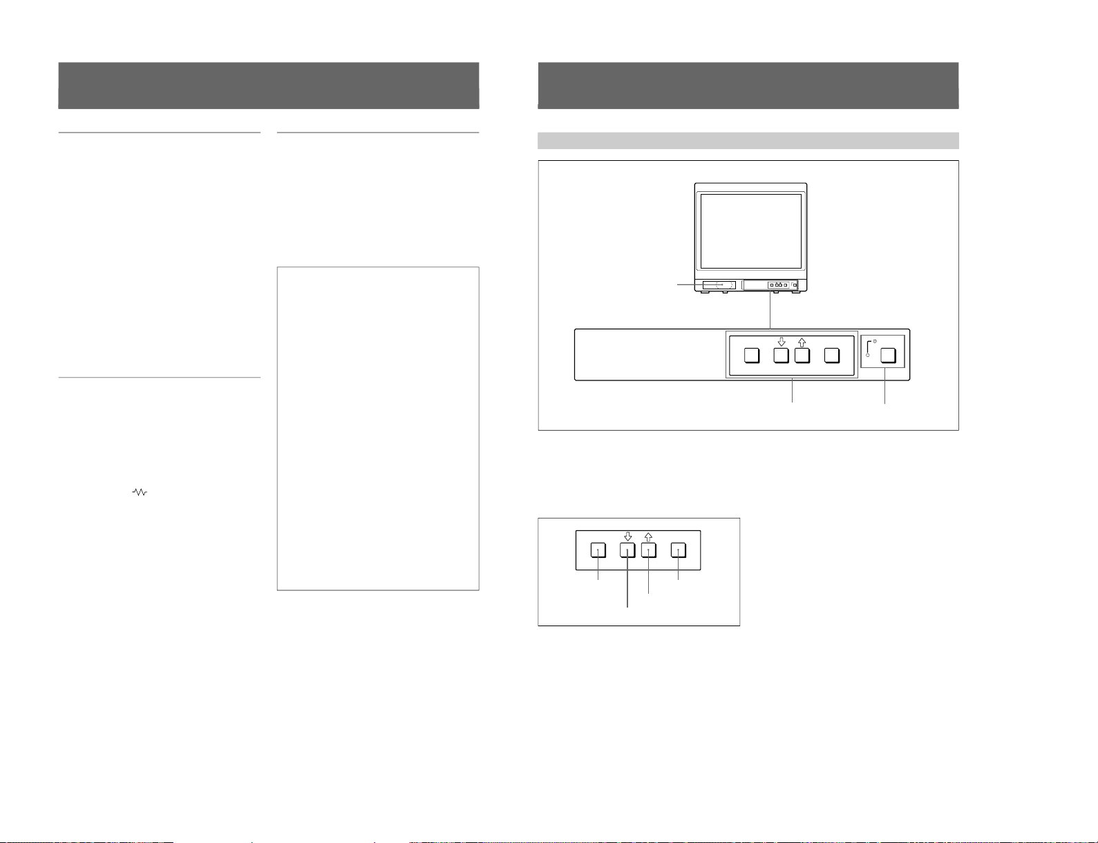
1-20
4
1) Trinitron
“Trinitron” is a registered trademark of Sony Corporation.
2) NTSC
4.43
The NTSC
4.43
system refers to an NTSC color system in which the subcarrier frequency is modified to 4.43 MHz. When an
NTSC recorded video program is played back with a Trident (PAL/SECAM/NTSC
4.43
) VTR, the NTSC
4.43
signal is output.
Features
Picture
Fine pitch Trinitron
1)
picture tube
The fine pitch Trinitron tube provides a high resolution
picture. Horizontal resolution is more than 500 TV
lines at the center of the picture.
Comb filter
When NTSC video signals are received, a comb filter
activates to make more accurate Y/C separation. This
contributes to less of a decrease in resolution, cross
color and cross luminance phenomena.
Beam current feedback circuit
The built-in beam current feedback circuit assures
stable white balance.
Four color system available
The monitor can display NTSC, PAL, SECAM, and
NTSC
4.43
2)
signals. The appropriate color system is
selected automatically.
Input
Y/C input connector
The video signal, split into the chrominance signal (C)
and the luminance signal (Y), can be input through this
connector, eliminating the interference between the
two signals, which tends to occur in a composite video
signal, ensuring video quality.
Automatic termination
(connector with
mark only)
The input connector is terminated at 75 ohms inside
when no cable is connected to the loop-through output
connector. When a cable is connected to an output
connector, the 75-ohm termination is automatically
released.
Functions
On-screen menus
You can set monitor operation settings by using the
on-screen menus.
EIA standard 19-inch rack mounting
By using an MB-502B mounting bracket (for a 14-inch
monitor, not supplied) or SLR-103A slide rail (for a
20-inch monitor, not supplied), the monitor can be
mounted in an EIA standard 19-inch rack.
Attention – when the product is installed in a rack:
•Elevated operating ambient temperature
If installed in a closed or multi-unit rack
assembly, the operating ambient temperature of
the rack environment may be greater than room
ambient.
Therefore, consideration should be given to
installing the equipment in an environment
compatible with the manufacturer’s maximum
rated ambient temperature of 0 to +35 ºC (Tmra).
•Reduced air flow
Installation of the equipment in a rack should be
such that the amount of air flow required for safe
operation of the equipment is not compromised.
•Mechanical loading
Mounting of the equipment in the rack should be
such that a hazardous condition is not achieved
due to uneven mechanical loading.
•Circuit overloading
Consideration should be given to the connection
of the equipment to the supply circuit and the
effect that overloading of circuits might have on
overcurrent protection and supply wiring.
Appropriate consideration of equipment
nameplate ratings should be used when
addressing this concern.
•Reliable earthing
Reliable earthing of rack-mounted equipment
should be maintained. Particular attention should
be given to supply connections other than direct
connections to the branch circuit (e.g., use of
power strips).
..........................................................................................................................................................................................................
5
Location and Function of Parts and Controls
Front
ENTER
MENU/
EXIT
POWER
ENTER
MENU/
EXIT
POWER
1
Speaker
2
MENU buttons
3
UPOWER switch
and indicator
ENTER
MENU/
EXIT
MENU/EXIT button
. button
> button
ENTER button
1 Speaker
2 MENU buttons
Press to make the menu appear.
For detailed information on MENU buttons, see “Operation
through On-Screen Menus” on page 9.
3 UPOWER switch and indicator
Press to turn the monitor on. The indicator lights in
green.
To turn the power off, press this again.
SIIA Chassis
Page 25
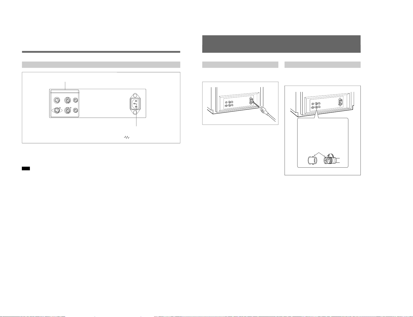
SIIA Chassis
6
Rear Panel
Location and Function of Parts and Controls
1 LINE connectors
Input connectors for the composite video, Y/C separate
video and audio signals and their loop-through output
connectors.
Note
The Y/C IN connector has priority over the VIDEO IN
connector.
When connecting the cable to the Y/C IN connector,
the Y/C IN connector is automatically selected and the
VIDEO IN connector is disconnected even if the cable
is connected.
Y/C IN connector (4-pin mini-DIN)
Connect to the Y/C separate output connector of a
video camera, VCR or other video equipment.
Y/C OUT connector (4-pin mini-DIN)
Loop-through output of the Y/C IN connector.
Connect to the Y/C separate input connector of a VCR
or another monitor.
When the cable is connected to this connector, the 75ohm termination of the input is automatically released,
and the signal input to the Y/C IN connector is output
from this connector.
VIDEO IN connector (BNC-type)
Connect to the video output connector of video
equipment, such as a VCR or a color video camera.
For a loop-through connection, connect to the video
output connector of another monitor.
VIDEO OUT connector (BNC-type)
Loop-through output of the VIDEO IN connector.
Connect to the video input connector for a VCR or
another monitor.
When the cable is connected to this connector, the 75ohm termination of the input is automatically released,
and the signal input to the VIDEO IN connector is
output from this connector.
AUDIO IN connector (phono jack)
Connect to the audio output connector of a VCR or
other equipment. For a loop-through connection,
connect to the audio output of another monitor.
AUDIO OUT connector (phono jack)
Loop-through output of the AUDIO IN connector.
Connect to the audio input connector of a VCR or
another monitor.
2 ⁄AC IN (inlet) connector
Connect the supplied AC power cord to this connector
and to a wall outlet.
(The mark indicates automatic termination.)
2
⁄AC IN connector
1
LINE connectors
LINE ~ AC IN
Y/CINVIDEOINAUDIO
IN
OUT OUT OUT
7
Connections
How to Connect the AC Power Cord
Connect the AC power cord (supplied) to the ⁄AC IN
connector and to a wall outlet.
Insert the connector into
the BNC connector on the
rear panel, matching the
slit and pin, and turn the
cable BNC connector
clockwise to secure the
BNC connector of a
coaxial cable.
How to Connect a Cable to a BNC Connector
Connect the coaxial cable with the BNC connectors to
the BNC connectors on the rear panel as illustrated
below.
1-21
Page 26

1-22
8
Using On-Screen Menus
You can make various settings and adjustments of the
monitor using the on-screen menus.
On-Screen Menu Configuration
Adjustment and setting menus
You can make desired adjustment or setting on
corresponding menu. The settings and adjustments
remain unchanged until next adjustment even if you
turn off the power.
To reset the settings and adjustments to the factorysettings, select “FACTORY PRESET” from 2d USER
MEMORY menu.
The on-screen menu is composed of the following two
menu types.
Item selection menu
You can select an adjustment and setting item such as
sound volume, contrast, brightness, color intensity,
color system and menu language by using the >,. and
ENTER buttons.
On-screen menu tree-chart
Regular screen
1a VOLUME menu
1b CONTRAST menu
1c BRIGHTNESS menu
1e PHASE menu
2a COLOR SELECT menu
2b DISPLAY menu
2c LANGUAGE menu
Item selection menus Adjustment and setting menus
2d USER MEMORY menu
1d CHROMA menu
1 MENU 1
2 MENU 2
9
Operation through On-Screen Menus
Menu operation buttons
There are four menu operation buttons on the front
panel of the monitor.
Button functions depend on the displayed menu. The
following table shows the button functions on the item
selection menus and adjustment and setting menus.
Button
1 MENU/EXIT
2 .
3 >
4 ENTER
a) You can use the ENTER button only on the 2d USER
MEMORY menu of the adjustment and setting menus.
Usable buttons depend on the displayed menu. Buttons
that can be used on the menu are displayed at the
bottom line of the screen. You can perform menu
operation using displayed buttons.
Operating procedures
To display the menu, follow this procedure.
1
Press the MENU/EXIT (1) button.
1 MENU 1 appears.
To select items other than ones not displayed on
MENU 1
Select 2 MENU 2 .
For details of how to select, see the “To change the item
selection menus” described later.
2
Move the cursor to the desired item by pressing the
. or > (2, 3) button.
3
Press the ENTER (4) button.
The adjustment and setting menu selected in step 2
appears.
For detailed information of menus, see “Functions of OnScreen Menus” on page 10.
ENTER
MENU/
EXIT
1 MENU/EXIT button
3 > button
4 ENTER button
2 . button
Menu
Usable buttons Usable buttons
Function on the
item selection
menus
To return to the
regular screen.
To move the cursor
downward.
To move the cursor
upward.
To decide a
selected item.
Function on the
adjustment and
setting menus
To return to the
item selection
menu.
To decrease value/
select item.
To increase value/
select item.
To decide a
selected item
a)
.
SIIA Chassis
Page 27

SIIA Chassis
10
To change the item selection menus
Select NEXT PAGE on the menu to display next item
selection menu and PREVIOUS PAGE on the menu to
display the previous item selection menu.
How to change the item selection menu
To return to the item selection menu from the
adjustment and setting menus
Press the MENU/EXIT (1) button on the currently
displayed adjustment and setting menu.
To close the menu (to return to the regular
screen)
Press the MENU/EXIT (1) button when the item
selection menu is displayed. The on-screen menu
disappears and the regular screen appears.
Using the Last Control Function
If you press the > or . button when the menu is not
displayed, one of the following menu items that you
adjusted last time is displayed.
•VOLUME
•CONTRAST
•BRIGHTNESS
•CHROMA
•PHASE
Then you can adjust the item immediately.
Functions of On-Screen Menus
Item selection menus
1 MENU 1
MENU 1 menu has the following selection items.
Item
VOLUME
CONTRAST
BRIGHTNESS
CHROMA
PHASE
2 MENU 2
MENU 2 menu has the following selection items.
Item
COLOR SELECT
DISPLAY
LANGUAGE
USER MEMORY
Adjustment and setting menu
1a VOLUME menu (Factory setting: 50)
Adjust the speaker volume.
The volume increases by pressing the > button.
The volume decreases by pressing . button.
Using On-Screen Menus
:
:
MENU 1 MENU 2
When selecting NEXT PAGE
When selecting PREVIOUS PAGE
Functions
To obtain the desired volume
To adjust the contrast
To adjust the brightness
To adjust the color intensity
To adjust the phase
Function
To select the color system of the
input signal
To select period of display
To select the menu language
To store and recall the values and
settings adjusted by a user, and recall
the factory-settings
11
1b CONTRAST menu (Factory setting: 80)
Adjust the contrast of the screen.
The contrast becomes higher by pressing the > button.
The contrast becomes lower by pressing . button.
1c BRIGHTNESS menu (Factory setting: STD)
Adjust the brightness of the screen.
The screen becomes brighter by pressing the > button.
The screen becomes darker by pressing . button.
1d CHROMA menu (Factory setting: STD)
Adjust the color intensity of the video signal.
The color intensity strengthens by pressing the >
button.
The color intensity weakens by pressing . button.
1e PHASE menu (Factory setting: STD)
Adjust the phase of the video signals.
The skin tone becomes greenish by pressing the >
button.
The skin tone becomes purplish by pressing the .
button.
Note
The phase of an NTSC composite video signal or a
Y/C separate signal can be corrected on this menu. The
PAL composite video signal or a Y/C separate signal
cannot be corrected.
2a COLOR SELECT menu
(Factory setting: AUTO)
Select the color system of the input signal.
AUTO: Input color systems are automatically
selected. When you input NTSC signal, comb filter
will activate. To monitor NTSC signal with trap
filter, select NTSC in this menu.
The factory setting of the COLOR SELECT menu
depends on destination.
SSM-14N5U/20N5U: NTSC
SSM-14N5E/20N5E/14N5A/20N5A: PAL
2b DISPLAY menu
(Factory setting: SHORT TIME)
Select the period of displaying the color system of the
current input signals.
The items have the following functions.
Item
SHORT TIME
LONG TIME
OFF
2c LANGUAGE menu
(Factory setting: ENGLISH)
Select the menu language among the five languages,
English, German, French, Italian and Spanish.
Function
To display the kind of color system
being used for several seconds on the
screen each time you change the
signal input.
To display the kind of color system
being used for approximately five
minutes on the screen each time you
change the signal input.
Not to display the kind of the color
system.
1-23
Page 28

1-24
12
Using On-Screen Menus
2d USER MEMORY menu
The items have the following functions.
Item
STORE
RECALL
FACTORY PRESET
a) The current settings and adjusted values are reset to the
factory settings. The values and settings adjusted and
stored in the internal memory by using the STORE
menu, however, are not changed. To reset internally
stored adjusted values and settings to the factory setting,
select FACTORY PRESET, first, then select STORE.
The color system of the input signal is reset to AUTO
even though the factory setting on the COLOR SELECT
menu is NTSC or PAL.
When you press the ENTER (4) button, the following
message is displayed for about two seconds. The
currently selected item becomes active when pressing
the ENTER (4) button.
This section may help you isolate the problem. Should
the problem persist, unplug the unit and contact your
Sony dealer or local authorized Sony service facility.
Symptom
If the picture is unstable,
when the input signal from
a security camera is
switched
Troubleshooting
Possible causes and
remedies
Select NTSC on the COLOR
SELECT menu when the
NTSC signal is input.
Select PAL when the PAL
signal is input.
Function
To store all adjustments and
settings currently set on each
menu into the internal memory.
To recall all adjustments and
settings currently stored in the
internal memory.
To reset the adjustments and
settings currently set on each
menu to the factory settings.
a)
13
Specifications
Video signal
Color system NTSC, PAL, SECAM, NTSC
4.43
Resolution 500 TV lines
Frequency response
LINE 6 MHz±3dB (Y signal)
Picture performance
Normal scan 7 % over scan of CRT effective
screen area
H. linearity Less than 8.0 % (typical)
V. linearity Less than 7.0 % (typical)
Color temperature D65
Inputs
LINE
Y/C IN 4-pin mini-DIN(×1)
See the pin assignment on this page.
VIDEO IN BNC connector (×1), 1Vp-p +3 dB,
–6 dB, sync negative
AUDIO IN Phono jack (×1), –5 dBu
a)
, more
than 47 kilo-ohms
a) 0 dBu = 0.775 Vr.m.s.
Outputs
LINE
Y/C OUT 4-pin mini-DIN (×1) loop-through,
Automatic 75 ohms termination
VIDEO OUT
BNC connector (×1) loop-through,
Automatic 75 ohms termination
AUDIO OUT
Phono jack (×1) loop-through
Speaker output Output level: 0.8 W
General
CRT SSM-14N5E/14N5U/14N5A:
14-inch CRT with P-22 phosphor
visible picture size 340 mm
(13-inch measured diagonally)
SSM-20N5E/20N5U/20N5A:
20-inch CRT with P-22 phosphor
visible picture size 490 mm
(19-inch measured diagonally)
Power consumption
SSM-14N5E/14N5U/14N5A: 80W
SSM-20N5U: 100 W
SSM-20N5E/20N5A: 105W
Power requirements
100 to 240 V AC, 50/60Hz
“For use of SSM-14N5U/20N5U”,
operate these monitors on 120 V AC.
Operating conditions
Temperature 0 to +35°C
Humidity 0 to 90% (no condensation)
Transport and Storage conditions
Temperature –10 to +40°C
Humidity 0 to 90%
Dimensions (w/h/d)
SSM-14N5E/14N5U/14N5A:
346 × 340 × 414 mm
(13
5
⁄8 × 13
1
⁄2 × 163⁄8 inches)
SSM-20N5E/20N5U/20N5A:
449 × 441 × 502 mm
(17
3
⁄4 × 173⁄
8
× 197⁄8 inches)
Mass SSM-14N5E/14N5U/14N5A:
Approx. 15 kg (33 lb 1 oz)
SSM-20N5E/20N5U/20N5A:
Approx. 28 kg (61 lb 12 oz)
Accesory supplied AC power cord (1)
Operating Instructions (1)
5
Pin assignment
Y/C IN connector (4-pin mini-DIN)
21
34
*
Pin No.
1
2
3
4
Design and specifications are subject to change
without notice.
Signal
Y-input
CHROMA
subcarrier-input
GND for Y-input
GND for CHROMA-
input
Description
1 Vp-p, sync negative, 75
ohms
0.286 Vp-p (NTSC), 300m
Vp-p (PAL), burst
Delay time between Y and
C: within 0 ± 100 nsec.,
75 ohms
GND
GND
SIIA Chassis
Page 29

SERVICE INFORMATION
2-1. CIRCUIT BOARDS LOCATION
SECTION 2
CA board (14-inch)
CB board (20-inch)
A board
Q board
SIIA Chassis
2-1
Page 30

2-2. DISASSEMBLY
2-2-1. Cabinet Removal 2-2-2. A Board Removal
1 Two screws
(Claw screw M4 x 8)
4 Cabinet
3 A board
2 PCB holder
20-inch only
2 Two screws
(Claw screw M4 x 8)
2-2-3. Service Position
3 Four screws
(+BVTP 4 x 16)
A board
1 Connector panel
Connector panel
Remove the connector
panel pressing the
bottom at BEZNET
which shows 0.
2-2
Connector (CN602)
SIIA Chassis
Page 31

2-2-4. Picture Tube Removal
5 CA board (14-inch)
CB board (20-inch)
2 Connector panel
Two claws
6 Deflection yoke
7 Four screws
(Hexagonal head
flange tapping screw 5)
8 Picture tube shield
9 Picture tube
1 Anode cap
3 PCB holder
20-inch only
4 A board
SIIA Chassis
Cushion
2-3
Page 32

2-2-5. Removal of Anode-cap
Note: Short circuit the anode of the picture tube and
the anode cap to the metal chassis, picture tube
shield or carbon painted on the picture tube,
after removing the anode.
1. Removing Procedures
(1) Turn up one side of the rubber cap in the direction
indicated by the arrow a.
a
a
(2) Using a thumb pull up the rubber cap firmly in the
direction indicated by the arrow b.
b
2. Handling Precautions
(1) Don’t hurt the surface of anode-caps with sharp shaped
material!
(2) Don’t press the rubber hardly not to hurt inside of
anode-caps!
A material fitting called as shatter-hook terminal is
built in the rubber.
(3) Don’t turn the foot of rubber over hardly!
The shatter-hook termianl will stick out or hurt the
rubber.
b
(3) When one side of the rubber cap is separated from the
anode button, the anode-cap can be removed by turning
up the rubber cap and pulling up it in the direction of
the arrow c.
c
Anode button
2-4
SIIA Chassis
Page 33

SECTION 3
SET-UP ADJUSTMENTS
3-1. PREPARATIONS (1)
[Tools|required]
. Oscilloscope
. Digital multimeter
. Degausser
. Video signal generator
. Variable AC power supply (or NF power supply)
. DC power supply
. Ammeter
Note: Perform the following adjustments 5 minutes
after turning on the power.
[Service|Mode]
This unit is provided with a service switch on the front
panel for various servicing adjustments. The following
describes how to use the switch.
1. Setting the Service Mode
With no menus displayed, press the [ENTER] and
[MENU] keys simultaneously. When Ver*** is displayed
on the screen, press the [ENTER] key twice.
Service Mode Screens
With no menus displayed state
Press the [MENU] and [ENTER] keys simultaneously.
Ver 3.00
Press the [ENTER] key once.
Screen for service engineer
LINE A
CXA PB PE
45 90 101110 000110
NO SYNC
Press the [ENTER] key once.
Service mode
2. Displaying the Service Mode
(4)
(1) (2)
(3)
Range of Service Mode Displays
(1) Serial number from “0 to 102” given to each service item.
(2) Name of service item.
(3) Adjustment data of the service item memorized in the
RAM currently. Changing this value enables
adjustments. Take note that if the adjustment values are
not saved in the EPROM, they will be lost when the
power is turned off or when the input is switched.
(4) Guidance on saving.
001 DESTINATION
00000
Press the [ENTER] key once.
Raster centering adjustment
RASTER CENTER ADJ MOD
Press the [ENTER] key once.
No DSD screen
Press the [ENTER] key once.
SIIA Chassis
Note: Use the double solid lined screens ( ) when
servicing.
3-1
Page 34

3. Exiting the Service Mode
To exit the service mode, switch to the raster center
adjustment mode, and press the [ENTER] and [MENU]
keys simultaneously.
4. Moving to the Desired Service Item
To go back to a previous service item, use the [MENU] +
[(] keys. To forward to a service item in front, use the
[MENU] + [)] keys. Pressing these keys continuously
will move the cursor continuously.
5. Changing the Service Data
The adjustment data increases when the [(] key is pressed
and decreases when the [)] key is pressed. Pressing these
keys continuously will increase or decrease the value
continuously.
6. Writing the Service Data
To write the data from the RAM to the EEPROM, press
the [MENU] and [ENTER] keys once, check that SAVE
is displayed at Guidance, and then press the [MENU] and
[ENTER] keys again. Take note that when SAVE≥≥ is
displayed at Guidance, the items displayed as well as all
data will be written.
7. Setting the Raster Centering Adjustment
Mode
Press the [ENTER] key another time in the service mode.
3-2
Service Items of EEPROM Data
No.
String
1 DESTINATION U/C: 1 U/C: 1
2 SHARP LEVEL 4 4
3 SHARP F0 1 1
4 PRE/OVER SHOOT 0 0
5 Y DLY NTSC COMB 4 4
6 Y DLY NTSC CVBS 4 4
7 Y DLY NTSC Y/C 4 4
8 Y DLY NT443 CVBS 4 4
9 Y DLY NT443 Y/C 4 4
10 Y DLY PAL CVBS 4 4
11 Y DLY PAL Y/C 4 4
12 Y DLY SECAM CVBS 4 4
13 Y DLY SECAM Y/C 4 4
14 Y DLY PAL-M CVBS 4 4
15 Y DLY PAL-M Y/C 4 4
16 CHROMA CENT 31 31
17 PH CENT NTSC COMB 33 33
18 PH CENT NTSC CVBS 31 31
19 PH CENT NTSC Y/C 31 31
20 PH CENT NT443CVBS 33 33
21 PH CENT NT443 Y/C 35 35
22 C BPF NTSC COMB 1 1
23 C BPF NTSC CVBS 1 1
24 C BPF NTSC Y/C 0 0
25 C BPF NT443 CVBS 1 1
26 C BPF NT443 Y/C 0 0
27 C BPF PAL CVBS 1 1
28 C BPF PAL Y/C 0 0
29 C BPF SECAM CVBS 1 1
30 C BPF SECAM Y/C 0 0
31 C BPF PAL-M CVBS 1 1
32 C BPF PAL-M Y/C 0 0
33 SUB BRT CVBS 33 33
34 SUB BRT RGB 33 33
35 SECAM ID START 1 1
36 SECAM ID STOP 2 2
37*SECAM BELL F0 33 33
38 SECAM ID LEVEL 3 3
39 C/O R ROUGH 3 3
40 C/O G ROUGH 3 3
Default Data
14-inch 20-inch
AEP: 2 AEP: 2
AUS: 3 AUS: 3
SIIA Chassis
Page 35

No.
String
41 C/O B ROUGH 3 3
42*C/O OFFSET CVBS 28 49
43*C/O R FINE CVBS 26 21
44*C/O G FINE CVBS 31 31
45*C/O B FINE CVBS 31 29
46*DRV ALL CVBS No. 47, 48 and 49 are displayed.
47*DRV R CVBS 42 31
48*DRV G CVBS 36 23
49*DRV B CVBS 19 11
50*C/O OFFSET SECAM 29 50
51*C/O R FINE SECAM 11 11
52*C/O G FINE SECAM 31 31
53*C/O B FINE SECAM 24 23
54*DRV ALL SECAM No. 55, 56 and 57 are displayed.
55*DRV R SECAM 41 31
56*DRV G SECAM 36 23
57*DRV B SECAM 19 11
58*C/O OFFSET RGB 40 49
59*C/O R FINE RGB 30 29
60*C/O G FINE RGB 31 31
61*C/O B FINE RGB 33 32
62*DRV ALL RGB No. 63, 64 and 65 are displayed.
63*DRV R RGB 44 39
64*DRV G RGB 38 33
65*DRV B RGB 19 15
66 H OSC F0 7 7
67 H MASK 1 1
68 H SYNC SEP 0 0
69 V SYNC SEP 0 0
70 V COUNTDOWN MODE 1 1
71*H CENT 60HZ CVBS 11 14
72*H CENT 60HZ RGB 10 12
73*H CENT 50HZ CVBS 18 21
74*H CENT 50HZ RGB 13 15
75*H CENT NTSC COMB 12 14
76 H BLK RGB 0 0
77 H BLK CVBS 1 1
78 H BLK L 60 CVBS 15 15
79 H BLK R 60 CVBS 0 0
80 H BLK L 60 RGB 15 15
Default Data
14-inch 20-inch
No.
String
81 H BLK R 60 RGB 0 0
82 H BLK L 50 CVBS 15 15
83 H BLK R 50 CVBS 0 0
84 H BLK L 50 RGB 15 15
85 H BLK R 50 RGB 0 0
86*BOW 7 7
87*ANGLE 7 7
88*V CENTER 32 31
89*V SIZE 22 23
90*V SIZE 16 : 9 63 63
91*VS-CORRECTION 3 5
92*V LINEARITY 7 6
93 V LIN UPPER 0 0
94 V LIN LOWER 0 0
95*H SIZE 21 18
96*H PIN PHASE 5 6
97*H PIN AMP 27 23
98*H CORNER PIN 31 34
99 EHT 8 8
100
SEC F0 TIME 0 0
101
SEC F0 DELTA 0 0
102
SEC F0 DELAY 0 0
Default Data
14-inch 20-inch
. The data of signals marked “*” can be changed freely.
. The data of signals without “*” marked is fixed.
SIIA Chassis
3-3
Page 36

3-2. PREPARATIONS (2)
3-3. OUTPUTTING IMAGES
. Set the video signal generator as follows, and input the
composite video signal.
Signal
COMPOSITE
VIDEO
NTSC
3.58 75 % WHITE 0.536 V
NTSC
4.43
PAL 75 % WHITE 0.525 V
SECAM
Signal Standard
Contents Level P-W
100 % WHITE 0.714 V
BURST 286 mV p-p
(GREEN) (632 mV p-p)
100 % WHITE 0.7 V
PAL BURST 300 mV p-p
(GREEN) (664 mV p-p)
. [|||] shows the name of the adjustment items of the
service mode.
Example [H|SIZE]
. If adjustments are performed in the service mode, save
the service data before turning off the power. Turning off
the power before saving the data will cause all adjusted
data to be lost.
Setting the AC Input Voltage
(1) Input the video signals and audio signals into each
terminal of the connector panel.
(2) Set the voltage of the variable AC power supply to
AC100 ±3 V (distortion factor: 3 % or less).
3-4. RASTER CENTERING
ADJUSTMENT
(1) Set the raster center adjustment mode.
Set the service mode according to “Setting the Service
Mode”, and press the [ENTER] key once to enter the
raster center adjustment mode.
(2) Adjust S501 on the A board so that the raster comes to
the horizontal direction center.
. Standard inspection state
Unless specified otherwise, set the video signal generator
to the following conditions and perform the adjustments
and inspections.
VOLUME 50
CONTRAST 80
BRIGHTNESS STD
CHROMA STD
PHASE STD
ASPECT RATIO 4 : 3
Adjust S501 so that the raster
comes to the horizontal center.
3-4
SIIA Chassis
Page 37

3-5. LANDING ADJUSTMENT
14-inch
1. Preparations
(1) To reduce geomagnetism effects, face the CRT screen
of this to the east or west.
(2) Loosen the fixture of the deflection yoke, and push
back the deflection yoke.
(3) Turn on the power switch, and degauss with the
degausser.
(4) Adjust the tilt of the deflection yoke.
2. Adjustment
Note: The white balance, G2, and convergence need
to be roughly adjusted beforehand.
(1) Set CONTRAST to MAX.
Set BRIGHTNESS to a position which gives a clear
view.
(2) Set the video signal generator to G (green) only.
(3) Adjust the purity knob so that G (green) comes to the
center of the screen and the R and B widths become
more or less the same. (Refer to Fig. 1.)
(4) Switch the video signal generator to B (blue) only, R
(red) only, and G (green) only, check that each color is
at the center of the screen. (Refer to Fig. 3, 6, and 9)
(5) Bring the deflection yoke forward gradually and adjust
it so that the R and B at the both sides of the screen
becomes green. (Refer to Fig. 2 and Fig. 3.)
(6) Moving the deflection yoke forward too much will
result in the pattern shown in Fig. 4. In such cases,
push back the deflection yoke. (Refer to Fig. 4 and
Fig. 3.)
(7) Switch the video signal generator to B (blue) only, and
check the pattern. (Refer to Fig. 6.)
(8) Switch the video signal generator to R (red) only, and
check the pattern. (Refer to Fig. 9.)
(9) If the landing cannot be obtained in the corners, paste
the magnet and perform adjustment.
(10)Switch to the all white signal and check the
uniformity.
(11)After setting the position of the deflection yoke, secure
it with fixture.
20-inch
RGB
Fig. 2
GBR
Fig. 5
TLV
YCH
Purity control
RV703
H.STAT
Purity control
RV703
H.STAT
RV702
FOCUS
RGB
A
Fig. 3
Fig. 6
G
B
Purity control
RV701
SCREEN
Purity control
A' = A
Fig. 1A'
B
RBG
Purity
Deflection
yoke
Purity
Deflection
yoke
G
R
Fig. 4
Fig. 7
SIIA Chassis
BRG
Fig. 8
R
Fig. 9
GRB
Fig. 10
3-5
Page 38

3-6. CONVERGENCE ADJUSTMENT
1. Input the dot pattern signal.
Set CONTRAST to the position at which it can be seen
clearly.
Set BRIGHTNESS to MIN.
2. Align the R, G, B dots in the horizontal direction at the
center of the screen using RV703 (H-STAT).
Note: If H-CENT was changed after adjusting H-
STAT, adjust H-STAT again. (The HSTAT can be changed by the H-CENT
switch.)
3. Align the top and bottom of R, G, B at the center of the
screen using the V-STAT (vertical static convergence)
magnets.
Note: After the V-STAT adjustment, always
paint the magnets to lock.
A
X
II'
B
X
II'
A
B
5. For VMC, use a 6-pole magnet to adjust so that the R
and B dots are symmetrical above and below the G dot.
RBG
Fixed
6-pole magnet
Perform the VMC
adjustment by rotating the
6-pole magnet to the left
and right without changing
the opening of it.
(Top section)
(Bottom section)
Adjust so that the displacement
of the dot is equal at the top
and bottom.
6. Repeat steps 2 to 5 until the convergence becomes
correct.
Note: Adjusting the convergence may affect the
landing. Therefore be sure to check the
landing again after completing this
adjustment.
7. After adjusting, paint each magnet to lock them.
Y
Good example
Y
Bad example
While maintaining the V-STAT magnet knobs A and B
at the same angle (I = I'), adjust the top and bottom
convergences. If A and B are asymmetrical (I = I'), it
will have a negative effect; the focus may not be
accurate, or the beam striking may occur.
4. For HMC, use a 6-pole magnet and adjust so that the R
and B dots are symmetrical at the left and right sides in
respect to the G dot.
II'
A
6-pole magnet
Perform the HMC adjustment
by changing the opening of
the 6-pole magnet.
B
A A'
Adjust the 6-pole magnet so
that A = A'. While maintaining
the I and I' angles equal,
adjust the 6-pole magnet.
BGR
14-inch
V.STAT convergence magnet
Purity
BMC magnet
20-inch
V.STAT convergence magnet
Purity
BMC magnet
3-6
SIIA Chassis
Page 39

3-7. INCLINATION OF DEFLECTION
YOKE ADJUSTMENT
If there is misconvergence at both sides of the X or Y axis
of the CRT screen, incline the deflection yoke in the arrow
direction to reduce the misconvergence for the entire CRT
screen to satisfy the tolerance specified.
1. Adjustment
2. Insert the wedges into the DY and CRT funnel face to
fix the deflection yoke. The number and position of the
wedges are shown in the figure below.
. If misconverged in the
opposite direction
Move the deflection yoke
downward.
BGR
R
G
B
GB
R
. If inclined to the left
Move the deflection
yoke to the right as
viewed from the
CRT screen.
L
RBLBR
. If misconverged in the
normal direction
Move the deflection yoke
downward.
R GB
B
B
G
G
R
R
BGR
. If inclined to the right
Move the deflection
yoke to the left as
viewed from the
CRT screen.
L L
BR RB
R
G
B
Position of the 14-inch wedge Position of the 20-inch wedge
3. The pattern below cannot be corrected by adjusting the
inclination of the deflection yoke.
R GB
R
G
B
(G) (G)
G
R
B
BGR
G
(G)
(G)
G
R
B
RB
G
R
B
Gun rotation
R
Beam is twisted at both
G
sides of the X and Y
B
axes respectively.
HCR large (small)
The G raster vertical
component is wider (or
narrower) at both sides of
the screen than those of
the R and B rasters.
VCR large (small)
The G raster vertical
component is wider (or
narrower) at both sides of
the screen than those of
the R and B rasters.
SIIA Chassis
3-7
Page 40

3-8. G2 ADJUSTMENT
3-9. WHITE BALANCE ADJUSTMENTS
1. Receive the 525 or 625 monoscope signal.
2. Set as follows in the service mode.
No. Item Data
PVM-14N5U/14N6U PVM-20N5U/20N6U
14N5E/14N6E 20N5E/20N6E
14N5A/14N6A 20N5A/20N6A
14N5MDE SSM-20N5U
SSM-14N5U 20N5E
14N5A 20N5A
14N5E
33 SUB BRT CVBS 31
40 C/O G ROUGH 3 7
42 C/O OFFSET CVBS 31
44 C/O G FINE CVBS 31
Data Setting by Service Mode
3. Connect the probe of the oscilloscope to the Q714
collector.
4. Adjust the Q714 collector IK pulse level to the
following voltage using RV701 (G2).
20-inch (RV701/CB board): G cathode = 149 ± 1 V
14-inch (RV701/CA board): G cathode = 136 ± 1 V
PICTUREV BLANKING
IK pulse
level of IK pulse
0 V
DC
3-9-1. VIDEO (Except SECAM) Adjustment
1. Select the LINE A input.
Set the monitor to the levels in the following table in
the service mode.
No. Item Data
PVM-14N5U/14N6U PVM-20N5U/20N6U
14N5E/14N6E 20N5E/20N6E
14N5A/14N6A 20N5A/20N6A
14N5MDE SSM-20N5U
SSM-14N5U 20N5E
14N5A 20N5A
14N5E
33 SUB BRT CVBS 31
34 SUB BRT RGB 31
39 C/O R ROUGH 3 7
40 C/O G ROUGH 3 7
41 C/O B ROUGH 3 7
45 C/O B FINE CVBS 31
52 C/O G FINE RGB 31
Data Setting by Service Mode
2. Input the all gray signal (Fig. 1) into LINE A.
3. Adjust the luminance to 3 ±0.2 nit using
42 [C/O|OFFSET|CVBS].
4. Adjust the white balance to the color temperature
shown in Table 1 using 43 [C/O|R|FINE|CVBS] and
45 [C/O|B|FINE|CVBS].
5. Repeat steps 3 and 4 so that the luminance and white
balance become the specifications shown in Table 1.
6. Input the window signal (Fig. 2) into LINE A.
7. Adjust the luminance to 150 ±1 nit using 46
[DRV|ALL|CVBS].
8. Adjust the white balance to the color temperature
shown in Table 1 using 47 [DRV|R|CVBS] and 49
[DRV|B|CVBS].
9. Repeat steps 7 and 8 so that the luminance and white
balance become the specifications shown in Table 1.
10.The cutoff varies by changing the drives. Therefore,
repeat steps 3 to 9 until the luminance and color
temperature of the arive and cutoff meet the
specification.
11.Repeat steps 2 and 10 so that the luminance and white
balance of the cutoff side (Fig. 1) and drive side (Fig.
2) become the specifications shown in Table 1.
12.Save the data.
3-8
SIIA Chassis
Page 41

11.Copy the data of the items adjusted in steps 1 to 10 to
the service items for adjusting the SECAM white
balance.
42 [C/O|OFFSET|CVBS]- Copied to → 50 [C/O|OFFSET|SECAM]
43 [C/O|R|FINE|CVBS] - Copied to → 51 [C/O|R|FINE|SECAM]
44 [C/O|G|FINE|CVBS] - Copied to → 52 [C/O|G|FINE|SECAM]
45 [C/O|B|FINE|CVBS] - Copied to → 53 [C/O|B|FINE|SECAM]
47 [DRV|R|CVBS] - Copied to → 55 [DRV|R|SECAM]
48 [DRV|G|CVBS] - Copied to → 56 [DRV|G|SECAM]
49 [DRV|B|CVBS] - Copied to → 57 [DRV|B|SECAM]
12.Save the adjustment data.
0.14 V p-p
Fig. 1. NTSC All Gray Signal (With Burst)
0.7 V p-p
Approx. 20 µsec
Fig. 2. NTSC Window Signal (With Burst)
Color Temperature Adjustment Error
D65 (x = 0.313, y = 0.329) ±1 JND
Table 1. Color Temperature
3-9-2. Analog RGB Adjustment
(PVM-14N6A, PVM-14N6E, PVM14N6U, PVM-20N6E, PVM-20N6U)
1. Select RGB signal.
2. Input the all gray signal (Fig. 3) into the RGB input.
3. Adjust the luminance to 3 ±0.2 nit using
58 [C/O|OFFSET|RGB].
4. Adjust the white balance to the color temperature
shown in Table 1 using 59 [C/O|R|FINE|RGB] and
61 [C/O|B|FINE|RGB].
5. Repeat steps 3 and 4 so that the luminance and white
balance become the specifications shown in Table 1.
6. Input the window signal (Fig. 4) into the RGB input.
7. Adjust the luminance to 150 ±1 nit using 62
[DRV|ALL|RGB].
8. Adjust the white balance to the color temperature
shown in Table 1 using 63 [DRV|R|RGB] and 65
[DRV|B|RGB].
9. Repeat steps 7 and 8 so that the luminance and white
balance become the specifications shown in Table 1.
10.The cutoff varies by changing the drives. Therefore,
repeat steps 3 to 9 until the luminance and color
temperature of the arive and cutoff meet the
specification.
11.Repeat steps 2 to 10 so that the luminance and white
balance of the cut-off side (Fig. 3) and drive side (Fig.
4) become the specifications shown in Table 1.
12.Save the adjustment data.
0.14 V p-p
Note: If there is no NTSC Window signal (with
burst), use Step signal.
SIIA Chassis
Fig. 3. 525/60 All Gray Signal
0.7 V p-p
Approx. 20 µsec
Fig. 4. 525/60 Window Signal
3-9
Page 42

3-9-3. SECAM Cut-off Adjustment
3-10. FOCUS ADJUSTMENT
1. Select LINE-A input.
2. Input the SECAM all gray signal (Fig. 5) into the
LINE-A.
3. Adjust the luminance to 3 ±0.2 nit using 50
[C/O|OFFSET|SECAM].
4. Adjust the white balance to the color temperature
shown in Table 1 using 51 [C/O|R|FINE|SECAM]
and 53 [C/O|B|FINE|SECAM].
5. Repeat steps 3 and 4 so that the luminance and white
balance become the specifications shown in Table 1.
6. Save the adjustment data.
0.14 V p-p
Fig.5. SECAM all gray signal
3-9-4. Sub-Brightness Adjustment
After completing the adjustments in 3-9-1, 3-9-2, and 3-93, set the sub-brightness data as follows.
Adjust RV702 of the CA board for the 14-inch model.
Adjust RV at the top of the FBT for the 20-inch model.
Focus
1. Input the 525 monoscope signal.
2. Adjust the focus so that the focus of the “30” at the
center of the screen becomes optimum.
3. Switch the signal to all white, and check the
uniformity.
No. Item Data
33 SUB BRT CVBS 33
34 SUB BRT RGB 33
3-10
SIIA Chassis
Page 43

SECTION 4
SAFETY RELATED ADJUSTMENTS
Note: The “4-1. B
Protection Circuit (Hold-down circuit) Check”
should always be performed when replacing
the following components marked on the
schematic diagram.
Marked products ( ) ....... C102, C331, C332, C333,
++
+ Voltage Check” and “4-2.
++
A board
C334, C335, C341, C390,
C507, D102, D103, C1454,
IC001, IC301, IC552, L505,
Q102, R107, R108, R110,
R324, R325, R326, R327,
R328, R329, R330, T501
A BOARD (B SIDE)
4-1. B
Note: Be sure to use the NF power supply. If not, use
Input voltage: 130 ±3 Vac
Input signal: Black
Controls: BRIGHTNESS 8 Minimum
Specification: Confirm that the voltage at C500 on the
++
+ VOLTAGE CHECK
++
an ordinary power supply of its distortion
factor is 3 % or less.
0
CONTRAST 8 Minimum
A board is 116.0 Vdc or less.
DC power supply
Digital multimeter
+
–
+
–
Digital multimeter
+
–
SIIA Chassis
4-1
Page 44

4-2. PROTECTION CIRCUIT (HOLD-
DOWN CIRCUIT) CHECK
Note: Be sure to use the NF power supply. If not, use
an ordinary power supply of its distortion
factor is 3% or less.
1. Protection Circuit Normal Operation Check
Input voltage: 120 ± 3 Vac
Input signal: Black
Controls: BRIGHTNESS 8 Minimum
CONTRAST 8 Minimum
Specification: Confirm that the voltage at Cathode of
D103 on the A board and ground is
greater than 99.0 Vdc.
2. Protection Circuit Operation Check (1)
Input voltage: 130 Vac
Input signal: Black
Controls: 14-inch: IABL = 40 ±20 µA
20-inch: IABL = 120 ±20 µA
Specification: Apply following voltage to Cathode of
D103 on the A board from the external
DC power supply and make sure that the
hold-down circuit doesn’t work.
14-inch: 119.6
20-inch: 145.2
+0
_0.4
+0
_0.4
Vac
Vac
3. Protection Circuit Operation Check (2)
Input voltage: 130 Vac
Input signal: Black
Controls: 14-inch: IABL = 40 ±20 µA
20-inch: IABL = 120 ±20 µA
Specification: Apply following voltage to Cathode of
D103 on the A board from the external
DC power supply and make sure that the
hold-down circuit works.
14-inch: 128.4
20-inch: 156.6
+0
_0.4
+0
_0.4
Vac
Vac
4-2
SIIA Chassis
Page 45

SECTION 5
CIRCUIT ADJUSTMENTS
5-1. PREPARATIONS
Input signals within ±2 % of the following specifications.
Signal
COMPOSITE
VIDEO
(75 % COLOR
BAR)
NTSC
3.58 75 % WHITE 0.536 V
NTSC
4.43
PAL 75 % WHITE 0.525 V
SECAM
Signal Standard
Contents Level P-W
100 % WHITE 0.714 V
BURST 286 mV p-p
(GREEN) (632 mV p-p)
100 % WHITE 0.7 V
PAL BURST 300 mV p-p
(GREEN) (664 mV p-p)
5-2. DEFLECTION SYSTEM ADJUSTMENT
5-2-1. Vertical Deflection Section Adjustment
Note: The 16 : 9 mode is available only for the PVM-
14N6U and PVM-20N6U.
525 Monoscope 625 Special CB
4 : 3 11.75 ±0.2 frames 12.8 ±0.3 frames
16 : 9
1. Input the 525 Monoscope signal.
2. Set CONTRAST to 80 %.
3. Set the service mode.
4. Adjust the vertical size to the specified value using
5. Check that the vertical size is within the specification.
6. Set the 16 : 9 mode.
7. Check that the vertical size is within the 16 : 9 mode
8. Return to the 4 : 3 mode.
9. Input the 625 special color bar signal.
10.Check that the vertical size is within the specification.
11.Set the 16 : 9 mode.
12.Check that the vertical size is within the 16 : 9 mode
Note 1: Set 89
Note 2: Measure the vertical size of the 16 : 9 mode
SIIA Chassis
14-inch 157 mm 157 mm
20-inch 221 mm 221 mm
Vertical Size Specifications
Set BRIGHTNESS to standard (STD).
89 [V|SIZE].
Optimize the vertical linearity using 92
[V|LINEARITY] and 91 [VS-CORRECTION].
Adjust the vertical centering using 88 [V|CENTER].
(Refer to Note 1.)
specification. (Refer to Note 2.)
specification.
[V|SIZE][V|SIZE]
[V|SIZE] within the “10 to 63” range.
[V|SIZE][V|SIZE]
Always set 93
[V|LIN|LOWER][V|LIN|LOWER]
[V|LIN|LOWER] to “0.”
[V|LIN|LOWER][V|LIN|LOWER]
[V|LIN|UPPER][V|LIN|UPPER]
[V|LIN|UPPER] and 94
[V|LIN|UPPER][V|LIN|UPPER]
with no flag signal in the vicinity of the image.
5-2-2. Horizontal Deflection Section Adjustment
Note 1: Make sure that the “3-4. Raster Centering
Adjustment” has been completed before
performing this adjustment.
Note 2: The 16 : 9 mode is available only for the PVM-
14N6U and PVM-20N6U.
1. Input the 525 Monoscope signal.
2. Set CONTRAST to 80 %.
Set BRIGHTNESS to standard (STD).
3. Set the service mode.
4. Adjust roughly the horizontal size to 16 frames using
95 [H|SIZE].
5. Adjust the horizontal deflection section using 97
[H|PIN|AMP], 96 [H|PIN|PHASE], 98
[H|CORNER|PIN], 86 [BOW], 87 [ANGLE], and
95 [H|SIZE].
While correcting the distortion, adjust so that the
horizontal and vertical of the screen become
perpendicular.
6. Set the 16 : 9 mode.
7. Check that the screen distortion is normal.
8. Input the 625 special color bar signal.
9. Check that the screen distortion is normal for both 4 : 3
and 16 : 9.
525 Monoscope 625 Special CB
4 : 3 15.75 ±0.2 frames 16.8 ±0.3 frames
16 : 9 15.75 ±0.2 frames 16.8 ±0.3 frames
Horizontal Size Specification
BOW (No. 86)
ANGLE (No. 87)
H PIN PHASE (No. 96)
H PIN AMP (No. 97)
H COR PIN (No. 98)
5-1
Page 46

5-2-3. Horizontal Centering Adjustment
The register for adjusting the horizontal centering requires
5 adjustments depending on the combination of the input
and signal.
No. Item Input Adjustment Signal
71 H CENT 60 Hz CVBS LINE-A 525 Monoscope
72 H CENT 60 Hz RGB RGB 525 Monoscope
73 H CENT 50 Hz CVBS LINE-A 625 special color bar
74 H CENT 50 Hz RGB RGB 625 special color bar
75 H CENT NTSC COMB LINE-A 525 Monoscope
1. Select LINE-A.
2. Input the 525 Monoscope signal into the LINE-A input.
3. Select NTSC at the COLOR SELECT menu.
4. Adjust the horizontal centering using 71
[H|CENT|60HZ|CVBS].
5. Select AUTO at the COLOR SELECT menu.
6. Adjust the horizontal centering using 75
[H|CENT|NTSC|COMB].
7. Input the 625 special color bar signal into the LINE-A
input.
8. Adjust the horizontal centering using 73
[H|CENT|50HZ|CVBS].
9. Save the data.
Note: The following items 10 to 16 are for PVM-
14N6A, PVM-14N6E, PVM-20N6A and PVM20N6E.
10.Select RGB.
11.Select SYNC ON G at the RGB SYNC menu.
12.Input the 525 Monoscope signal into the RGB input.
13.Adjust the horizontal centering using 72
[H|CENT|60HZ|RGB].
14.Input the 625 special color bar signal into the RGB
input.
15.Adjust the horizontal centering using 74
[H|CENT|50HZ|RGB].
16.Save the data.
5-2
SIIA Chassis
Page 47

SECTION 6
1
TOP VIEW
1
TOP VIEW
1
TOP VIEW
E
3
CATHODE
ANODE
|
SEMICONDUCTORS
IC, TRANSISTOR, DIODE
BA4558
MM1096BD
M24C01-BN6
TDA7052A
UPC4558C
1
TOP VIEW
8Pin DIP
BA7604N
MARKING SIDE VIEW
1
10Pin SIP
CXA2060BS
48Pin DIP
CXA85116B-670S
64Pin DIP
MC14052BCP
16Pin DIP
MC7805CT
MC7809CT
NJM7809FA
SE115N
TA7805S
STV9379
1
BF421
BF871
2SA1091O-TPE2
2SA1091-O
2SA933S-RT
7
DAN202K
DAN202K-T-146
3
2
1
2
1
MTZJ-11A
MTZJ-5.1B
MTZJ-6.2C
MTZJ-7.5B
RD5.1ESB2
CATHODE
EGP20G
E
C
B
2SA1037AK-T146-Q
2SC1623-L5L6
2SA2412K-T-146-Q
C
B
E
2SA1175-HFE
EL1Z
EL1Z-V1
GP08D
GP08DPKG23
RGP02-17EL-6433
RGP02-17PKG23
RGP10GPKG23
MTZJ-36B
RU4AM-T3
ANODE
CATHODE
ANODE
2SC1740S-RT
2SC2785-HFE
LETTER SID
ERC06-15S
RC111YS
6
RGP15J-6040G23
E
C
B
2SC3209LK
2SC3209LK-TP
E
C
B
1SS133T-77
CATHODE
ANODE
FML-G12S
CATHODE
ANODE
SLR-56MC3F
1
1
2
ANODE
5
4
2
3
6
5
4
3
CATHODE
IN
GND
STR-S6708
1
n
SIIA Chassis
OUT
2SC3852A
GPU4JL-6088
2SD2394-EF
{
‘
‘
|
{
‘
B
C
E
‘
2SD1878-CA
2SD1877S-SONY-CA
N
B
C
E
6-1
Page 48

Page 49

NOTE:
. Items with no part number and no
description are not stocked because they
are seldom required for routine service.
SECTION 7
EXPLODED VIEWS
. The construction parts of an assembled
part are indicated with a collation number
in the remark column.
. Items marked “*” are not stocked since
they are seldom required for routine
service. Some delay should be
anticipated when ordering these items.
The components identified by
! are critical for safety.
mark
Replace only with part number
specified.
Les composants identifies par
une marque
pour la securite. Ne les
remplacer que par une piece
portant le numero specifie.
! sont critiques
SIIA Chassis
7-1
Page 50

CHASSIS
7-1. CHASSIS (14-INCH)
30
32
24
21
31
20
27
4
2
26
25
16
29
28
6
8
1
7
5
8
2
6
13
4
3
10
11
9
33
34
35
36
19
17 18
14 15
12
22
23
PVM-14N5MDE
39
38
37
18
2
Ref.No. Part No. Description Remark Ref.No. Part No. Description Remark
1 X-4033-973-1 BEZNET ASSY
(PVM-14N6A/14N6E/14N6U) 2
X-4033-974-1 BEZNET ASSY
(PVM-14N5A/14N5E/14N5U) 2
24 * A-1270-399-A Q BOARD, COMPLETE
(PVM-14N6A/14N6E/14N6U)
*A-1270-401-A Q BOARD, COMPLETE
(SSM-14N5A/14N5E/14N5U)
X-4033-975-1 BEZNET ASSY
X-4033-976-2 BEZNET ASSY (PVM-14N5MDE) 2
(SSM-14N5A/14N5E/14N5U) 2
2 4-039-358-01 SCREW (4X16), (+) BV TAPPING
25 4-050-074-03 PANEL, CONNECTOR
26 4-050-082-02 LABEL, CONNECTOR
(PVM-14N6A/14N6E/14N6U)
4-050-082-12 LABEL, CONNECTOR
3 1-505-188-11 SPEAKER (4X7CM)
4 4-039-356-01 SCREW (3X12), (+) BV TAPPING
5 4-050-073-11 CABINET (except PVM-14N5MDE)
A-1501-211-B CABINET (PVM-14N5MDE)
4-050-082-22 LABEL, CONNECTOR
4-050-082-32 LABEL, CONNECTOR (PVM-14N5MDE)
(PVM-14N5A/14N5E/14N5U)
(SSM-14N5A/14N5E/14N5U)
6 4-389-320-21 HANDLE
27 4-050-081-01 PANEL, REAR
7 4-391-825-01 RIVET, NYLON
8 4-847-802-11 SCREW (M4X8), CLAW
9 ! 8-738-342-05 PICTURE TUBE (M34KBE10X)
10 3-704-495-01 SPACER, DY
11 ! 8-451-472-11 DEFLECTION YOKE (Y14MGAT)
28 * A-1298-614-A A BOARD, COMPLETE
(PVM-14N5A/14N5E/14N5U)
*A-1298-615-A A BOARD, COMPLETE
(PVM-14N6A/14N6E/14N6U)
*A-1298-623-A A BOARD, COMPLETE
(SSM-14N5A/14N5E/14N5U)
12 4-847-334-02 PURSE LOCK (DIA.15)
*A-1298-624-A A BOARD, COMPLETE (PVM-14N5MDE)
13 * A-1331-827-A CA BOARD, COMPLETE
14 * 4-374-912-01 COVER (MAIN), CV VOL
15 * 4-374-913-01 COVER (REAR LID), CV VOL
16 1-543-653-11 CORE ASSY, BEAD(DIVISION TYPE)
29 ! 8-598-830-00 TRANSFORMER ASSY, FLYBACK
(NX-4301//U2A4)
30 ! 1-576-231-11 FUSE (H.B.C.) (4A/250V)
31 ! 1-571-433-31 SWITCH, PUSH (AC POWER)
17 ! 1-426-442-21 COIL, DEMAGNETIZATION
18 * 4-316-015-00 HOLDER, WIRE
32 4-050-085-01 BUTTON, POWER SWITCH
33 4-308-870-00 CLIP, LEAD WIRE
19 4-203-648-01 SCREW (5), SELF TAPPING
20 4-050-078-01 SCREW, +B M3X10
21 ! 1-251-263-11 INLET, AC
34 1-452-032-00 MAGNET,DISK ; 10mmø
35 1-452-094-00 MAGNET, ROTATABLE DISK ; 15mmø
36 X-4309-608-0 PERMALLOY ASSY, CONVERGENCE
22 4-050-077-01 SCREW +PSW M4X8
23 * 1-900-214-07 WIRE ASSY, SEFETY EARTH
37 * 3-175-741-01 NUT (PVM-14N5MDE)
38 * 3-175-742-01 WASHER (PVM-14N5MDE)
24 * A-1270-398-A Q BOARD, COMPLETE
7-2
(PVM-14N5A/14N5E/14N5MDE/14N5U)
39 * 3-175-740-01 TERMINAL (PVM-14N5MDE)
SIIA Chassis
Page 51

7-2. CHASSIS (20-INCH)
CHASSIS
58
56
51
52
58
54
56
55
53
57
59
61
60
64
62
52
87
67
63
84
85
86
65
69
82
73
72
74
80
77
71
70
54
52
76
75
66
68
83
79
78
81
Ref.No. Part No. Description Remark Ref.No. Part No. Description Remark
51 X-4033-977-1 BEZNET ASSY
(PVM-20N6A/20N6E/20N6U)
X-4033-978-1 BEZNET ASSY
(PVM-20N5A/20N5E/20N5U)
X-4033-979-1 BEZNET ASSY
(SSM-20N5A/20N5E/20N5U)
52 4-039-358-01 SCREW (4X16), (+) BV TAPPING
53 1-505-188-11 SPEAKER (4X7CM)
74 *A-1270-398-A Q BOARD, COMPLETE
(PVM-20N5A/20N5E/20N5U)
*A-1270-399-A Q BOARD, COMPLETE
(PVM-20N6A/20N6E/20N6U)
*A-1270-401-A Q BOARD, COMPLETE
(SSM-20N5A/20N5E/20N5U)
75 4-050-074-03 PANEL, CONNECTOR
76 4-050-082-02 LABEL, CONNECTOR
(PVM-20N6A/20N6E/20N6U)
54 4-039-356-01 SCREW (3X12), (+) BV TAPPING
55 4-050-060-33 CABINET
56 4-389-320-21 HANDLE
57 4-391-825-01 RIVET, NYLON
58 4-847-802-11 SCREW (M4X8), CLAW
76 4-050-082-12 LABEL, CONNECTOR
(PVM-20N5A/20N5E/20N5U)
4-050-082-22 LABEL, CONNECTOR
(SSM-20N5A/20N5E/20N5U)
77 4-050-063-01 PANEL, REAR
59 ! 8-736-135-05 PICTURE TUBE (M49KGH10X)
60 3-704-495-01 SPACER, DY
61 ! 1-451-349-11 DEFLECTION YOKE (Y20FZA)
62 4-030-120-01 PLATE, CORRECTION, TLV
78 *A-1298-619-A A BOARD, COMPLETE
(PVM-20N5A/20N5E/20N5U)
*A-1298-621-A A BOARD, COMPLETE
(PVM-20N6A/20N6E/20N6U)
63 * A-1331-828-A CB BOARD, COMPLETE
78 *A-1298-622-A A BOARD, COMPLETE
64 3-704-372-01 HOLDER, HV CABLE
65 4-369-318-31 SPRING, TENSION
66 1-543-653-11 CORE ASSY, BEAD (DIVISION TYPE)
67 ! 1-411-750-11 COIL, DEMAGNETIC
68 4-041-021-02 HOLDER, DEGAUSE COIL
79 ! 1-453-277-11 TRANSFORMER ASSY, FLYBACK
80 ! 1-576-231-11 FUSE (H.B.C.) (4A/250V)
81 ! 1-571-433-31 SWITCH, PUSH (AC POWER)
(SSM-20N5A/20N5E/20N5U)
(NX-4008//U2A4)
82 4-050-085-01 BUTTON, POWER SWITCH
69 4-203-648-01 SCREW (5), SELF TAPPING
70 4-050-078-01 SCREW, +B M3X10
71 ! 1-251-263-11 INLET, AC
72 4-050-077-01 SCREW +PSW M4X8
73 * 1-900-214-07 WIRE ASSY, SEFETY EARTH
83 4-050-066-01 HOLDER, PWB
84 4-308-870-00 CLIP, LEAD WIRE
85 1-452-032-00 MAGNET,DISK ; 10mmø
86 1-452-094-00 MAGNET, ROTATABLE DISK ; 15mmø
87 X-4309-608-0 PERMALLOY ASSY, CONVERGENCE
SIIA Chassis
7-3
Page 52

Page 53

NOTE:
The components identified by
! are critical for safety.
mark
Replace only with part number
specified.
Les composants identifies par
une marque
pour la securite. Ne les
remplacer que par une piece
portant le numero specifie.
! sont critiques
SECTION 8
ELECTRICAL PARTS LIST
. Items marked “*” are not stocked since they are
seldom required for routine service. Some delay
should be anticipated when ordering these items.
. All variable and adjustable resistors have
characteristic curve B, unless otherwise noted.
RESISTORS
. All resistors are in ohms
. F: nonflammable
When indicating parts by reference number,
please include the board name.
. CAPACITORS
PF: µµ F
. There are some cases the reference number on
one board overlaps on the other board. Therefore,
when ordering parts by the reference number,
please include the board name.
SIIA Chassis
8-1
Page 54

[Q]
Ref.No. Part No. Description Remark Ref.No. Part No. Description Remark
*A-1270-398-A Q BOARD, COMPLETE
****************************
(PVM-14N5A/E/U, 14N5MDE, 20N5A/E/U)
*A-1270-399-A Q BOARD, COMPLETE
****************************
(PVM-14N6A/E/U, 20N6A/E/U)
*A-1270-401-A Q BOARD, COMPLETE
****************************
(SSM-14N5A/E/U, 20N5A/E/U)
1-694-045-11 TERMINAL BOARD ASSY, I/O
(J1301, 1302, 1305, 1306, 1311-1317, 1320, 1321)
(PVM-14N6A/E/U, 20N6A/E/U)
1-694-046-11 TERMINAL BOARD ASSY, I/O
(J1301, 1302, 1305, 1306, 1317, 1320)
(PVM-14N5A/E/U, 14N5MDE, 20N5A/E/U)
1-694-047-11 TERMINAL BOARD ASSY, I/O
(J1301, 1302, 1305, 1306) (SSM-14N5A/E/U, 20N5A/E/U)
7-627-557-48 SCREW (2.6X10), +P TAPPING
C1350 1-163-235-11 CERAMIC CHIP 22PF 5% 50V
(except SSM-14N5A/E/U, 20N5A/E/U)
C1350 1-216-295-91 SHORT 0
(SSM-14N5A/E/U, 20N5A/E/U)
C1351 1-163-235-11 CERAMIC CHIP 22PF 5% 50V
(except SSM-14N5A/E/U, 20N5A/E/U)
C1351 1-216-295-91 SHORT 0
(SSM-14N5A/E/U, 20N5A/E/U)
C1352 1-163-235-11 CERAMIC CHIP 22PF 5% 50V
(except SSM-14N5A/E/U, 20N5A/E/U)
C1352 1-216-295-91 SHORT 0
(SSM-14N5A/E/U, 20N5A/E/U)
C1353 1-163-235-11 CERAMIC CHIP 22PF 5% 50V
(except SSM-14N5A/E/U, 20N5A/E/U)
C1353 1-216-295-91 SHORT 0
(SSM-14N5A/E/U, 20N5A/E/U)
C1354 1-163-021-91 CERAMIC CHIP 0.01µF 10% 50V
C1355 1-163-235-11 CERAMIC CHIP 22PF 5% 50V
C1356 1-163-235-11 CERAMIC CHIP 22PF 5% 50V
C1357 1-163-021-91 CERAMIC CHIP 0.01µF 10% 50V
<CAPACITOR>
C1303 1-164-232-11 CERAMIC CHIP 0.01µF 10% 50V
C1304 1-113-340-11 ELECT 47µF 20% 25V
C1305 1-164-005-11 CERAMIC CHIP 0.47µF 25V
C1308 1-126-795-11 ELECT 10µF 20% 25V
C1317 1-126-795-11 ELECT 10µF 20% 25V
(PVM-14N6A/E/U, 20N6A/E/U)
C1319 1-126-795-11 ELECT 10µF 20% 25V
(PVM-14N6A/E/U, 20N6A/E/U)
C1320 1-126-795-11 ELECT 10µF 20% 25V
(PVM-14N6A/E/U, 20N6A/E/U)
C1322 1-126-795-11 ELECT 10µF 20% 25V
(PVM-14N6A/E/U, 20N6A/E/U)
C1325 1-126-795-11 ELECT 10µF 20% 25V
(PVM-14N6A/E/U, 20N6A/E/U)
C1326 1-126-795-11 ELECT 10µF 20% 25V
C1327 1-126-795-11 ELECT 10µF 20% 25V
C1328 1-126-795-11 ELECT 10µF 20% 25V
(except SSM-14N5A/E/U, 20N5A/E/U)
C1329 1-126-795-11 ELECT 10µF 20% 25V
(except SSM-14N5A/E/U, 20N5A/E/U)
C1330 1-164-232-11 CERAMIC CHIP 0.01µF 10% 50V
(except SSM-14N5A/E/U, 20N5A/E/U)
C1331 1-126-795-11 ELECT 10µF 20% 25V
(except SSM-14N5A/E/U, 20N5A/E/U)
C1332 1-163-121-00 CERAMIC CHIP 150PF 5% 50V
C1333 1-163-121-00 CERAMIC CHIP 150PF 5% 50V
(except SSM-14N5A/E/U, 20N5A/E/U)
C1334 1-163-121-00 CERAMIC CHIP 150PF 5% 50V
(PVM-14N6A/E/U, 20N6A/E/U)
C1335 1-164-232-11 CERAMIC CHIP 0.01µF 10% 50V
C1341 1-163-021-91 CERAMIC CHIP 0.01µF 10% 50V
C1342 1-163-235-11 CERAMIC CHIP 22PF 5% 50V
C1343 1-163-235-11 CERAMIC CHIP 22PF 5% 50V
C1344 1-163-021-91 CERAMIC CHIP 0.01µF 10% 50V
C1345 1-163-235-11 CERAMIC CHIP 22PF 5% 50V
C1346 1-163-021-91 CERAMIC CHIP 0.01µF 10% 50V
C1347 1-164-005-11 CERAMIC CHIP 0.47µF 25V
C1348 1-163-021-91 CERAMIC CHIP 0.01µF 10% 50V
C1349 1-163-235-11 CERAMIC CHIP 22PF 5% 50V
C1358 1-163-235-11 CERAMIC CHIP 22PF 5% 50V
C1359 1-113-340-11 ELECT 47µF 20% 25V
C1360 1-113-340-11 ELECT 47µF 20% 25V
C1361 1-113-340-11 ELECT 47µF 20% 25V
C1362 1-113-340-11 ELECT 47µF 20% 25V
<CONNECTOR>
CN1301 *1-564-521-11 PLUG, CONNECTOR 6P
CN1302 *1-564-522-11 PLUG, CONNECTOR 7P
(except SSM-14N5A/E/U, 20N5A/E/U)
CN1303 *1-564-522-11 PLUG, CONNECTOR 7P
(except PVM-14N5A/E/U, 14N5MDE, 20N5A/E/U)
<DIODE>
D1300 8-719-991-33 DIODE 1SS133T-77
D1301 8-719-991-33 DIODE 1SS133T-77
D1302 8-719-991-33 DIODE 1SS133T-77
D1303 8-719-991-33 DIODE 1SS133T-77
D1304 8-719-991-33 DIODE 1SS133T-77
D1305 8-719-991-33 DIODE 1SS133T-77
D1308 8-719-991-33 DIODE 1SS133T-77
D1309 8-719-991-33 DIODE 1SS133T-77
D1314 8-719-991-33 DIODE 1SS133T-77
(PVM-14N6A/E/U, 20N6A/E/U)
D1315 8-719-991-33 DIODE 1SS133T-77
(PVM-14N6A/E/U, 20N6A/E/U)
D1316 8-719-991-33 DIODE 1SS133T-77
(PVM-14N6A/E/U, 20N6A/E/U)
D1317 8-719-991-33 DIODE 1SS133T-77
(PVM-14N6A/E/U, 20N6A/E/U)
D1318 8-719-991-33 DIODE 1SS133T-77
(PVM-14N6A/E/U, 20N6A/E/U)
D1319 8-719-991-33 DIODE 1SS133T-77
(PVM-14N6A/E/U, 20N6A/E/U)
D1320 8-719-991-33 DIODE 1SS133T-77
(PVM-14N6A/E/U, 20N6A/E/U)
D1321 8-719-991-33 DIODE 1SS133T-77
(PVM-14N6A/E/U, 20N6A/E/U)
D1322 8-719-923-74 DIODE MTZJ-T-77-11A
(PVM-14N6A/E/U, 20N6A/E/U)
8-2
SIIA Chassis
Page 55

[Q]
Ref.No. Part No. Description Remark Ref.No. Part No. Description Remark
D1324 8-719-991-33 DIODE 1SS133T-77
(except SSM-14N5A/E/U, 20N5A/E/U)
D1325 8-719-991-33 DIODE 1SS133T-77
(except SSM-14N5A/E/U, 20N5A/E/U)
D1326 8-719-991-33 DIODE 1SS133T-77
(except SSM-14N5A/E/U, 20N5A/E/U)
D1327 8-719-991-33 DIODE 1SS133T-77
(except SSM-14N5A/E/U, 20N5A/E/U)
D1328 8-719-991-33 DIODE 1SS133T-77
(except SSM-14N5A/E/U, 20N5A/E/U)
D1329 8-719-991-33 DIODE 1SS133T-77
(except SSM-14N5A/E/U, 20N5A/E/U)
D1330 8-719-991-33 DIODE 1SS133T-77
(except SSM-14N5A/E/U, 20N5A/E/U)
D1331 8-719-991-33 DIODE 1SS133T-77
(except SSM-14N5A/E/U, 20N5A/E/U)
D1332 8-719-991-33 DIODE 1SS133T-77
(PVM-14N6A/E/U, 20N6A/E/U)
D1333 8-719-991-33 DIODE 1SS133T-77
(PVM-14N6A/E/U, 20N6A/E/U)
<IC>
IC1301 8-759-984-96 IC BA7604N
<JACK>
R1317 1-216-065-00 RES,CHIP 4.7K 5% 1/10W
R1318 1-216-119-00 RES,CHIP 820K 5% 1/10W
R1319 1-216-107-00 RES,CHIP 270K 5% 1/10W
R1320 1-216-097-00 RES,CHIP 100K 5% 1/10W
R1321 1-216-095-00 RES,CHIP 82K 5% 1/10W
R1331 1-216-049-91 RES,CHIP 1K 5% 1/10W
(PVM-14N6A/E/U, 20N6A/E/U)
R1332 1-216-073-00 RES,CHIP 10K 5% 1/10W
(PVM-14N6A/E/U, 20N6A/E/U)
R1333 1-216-073-00 RES,CHIP 10K 5% 1/10W
(PVM-14N6A/E/U, 20N6A/E/U)
R1335 1-216-049-91 RES,CHIP 1K 5% 1/10W
(PVM-14N6A/E/U, 20N6A/E/U)
R1336 1-216-073-00 RES,CHIP 10K 5% 1/10W
(PVM-14N6A/E/U, 20N6A/E/U)
R1337 1-216-073-00 RES,CHIP 10K 5% 1/10W
(PVM-14N6A/E/U, 20N6A/E/U)
R1338 1-216-009-00 RES,CHIP 22 5% 1/10W
(PVM-14N6A/E/U, 20N6A/E/U)
R1339 1-214-702-00 METAL 75 1% 1/4W
(PVM-14N6A/E/U, 20N6A/E/U)
R1340 1-216-049-91 RES,CHIP 1K 5% 1/10W
(PVM-14N6A/E/U, 20N6A/E/U)
R1341 1-216-073-00 RES,CHIP 10K 5% 1/10W
(PVM-14N6A/E/U, 20N6A/E/U)
R1342 1-216-073-00 RES,CHIP 10K 5% 1/10W
(PVM-14N6A/E/U, 20N6A/E/U)
J1303 1-565-167-12 TERMINAL, (S) (WITH SW) 4P
J1304 1-569-578-11 TERMINAL, S (WITH SW)
J1319 1-565-167-12 TERMINAL, (S) (WITH SW) 4P
(except SSM-14N5A/E/U, 20N5A/E/U)
<TRANSISTOR>
Q1302 8-729-119-78 TRANSISTOR 2SC2785-HFE
Q1305 8-729-119-76 TRANSISTOR 2SA1175-HFE
Q1308 8-729-119-78 TRANSISTOR 2SC2785-HFE
(PVM-14N6A/E/U, 20N6A/E/U)
Q1309 8-729-119-78 TRANSISTOR 2SC2785-HFE
(PVM-14N6A/E/U, 20N6A/E/U)
Q1310 8-729-119-78 TRANSISTOR 2SC2785-HFE
(PVM-14N6A/E/U, 20N6A/E/U)
Q1311 8-729-119-76 TRANSISTOR 2SA1175-HFE
(PVM-14N6A/E/U, 20N6A/E/U)
Q1312 8-729-119-78 TRANSISTOR 2SC2785-HFE
(PVM-14N6A/E/U, 20N6A/E/U)
Q1313 8-729-119-78 TRANSISTOR 2SC2785-HFE
(except SSM-14N5A/E/U, 20N5A/E/U)
Q1314 8-729-119-76 TRANSISTOR 2SA1175-HFE
(except SSM-14N5A/E/U, 20N5A/E/U)
<RESISTOR>
R1303 1-216-009-00 RES,CHIP 22 5% 1/10W
R1304 1-214-702-00 METAL 75 1% 1/4W
R1305 1-216-065-00 RES,CHIP 4.7K 5% 1/10W
R1307 1-214-702-00 METAL 75 1% 1/4W
R1308 1-216-059-00 RES,CHIP 2.7K 5% 1/10W
R1309 1-216-073-00 RES,CHIP 10K 5% 1/10W
R1310 1-216-073-00 RES,CHIP 10K 5% 1/10W
R1311 1-214-702-00 METAL 75 1% 1/4W
R1312 1-216-065-00 RES,CHIP 4.7K 5% 1/10W
R1343 1-216-009-00 RES,CHIP 22 5% 1/10W
(PVM-14N6A/E/U, 20N6A/E/U)
R1344 1-214-702-00 METAL 75 1% 1/4W
(PVM-14N6A/E/U, 20N6A/E/U)
R1345 1-216-009-00 RES,CHIP 22 5% 1/10W
(PVM-14N6A/E/U, 20N6A/E/U)
R1346 1-214-702-00 METAL 75 1% 1/4W
(PVM-14N6A/E/U, 20N6A/E/U)
R1347 1-216-065-00 RES,CHIP 4.7K 5% 1/10W
(PVM-14N6A/E/U, 20N6A/E/U)
R1348 1-216-119-00 RES,CHIP 820K 5% 1/10W
(PVM-14N6A/E/U, 20N6A/E/U)
R1349 1-216-107-00 RES,CHIP 270K 5% 1/10W
(PVM-14N6A/E/U, 20N6A/E/U)
R1350 1-216-097-00 RES,CHIP 100K 5% 1/10W
(PVM-14N6A/E/U, 20N6A/E/U)
R1351 1-216-095-00 RES,CHIP 82K 5% 1/10W
(PVM-14N6A/E/U, 20N6A/E/U)
R1352 1-216-059-00 RES,CHIP 2.7K 5% 1/10W
(PVM-14N6A/E/U, 20N6A/E/U)
R1355 1-216-049-91 RES,CHIP 1K 5% 1/10W
(PVM-14N6A/E/U, 20N6A/E/U)
R1356 1-214-702-00 METAL 75 1% 1/4W
(PVM-14N6A/E/U, 20N6A/E/U)
R1358 1-247-791-91 CARBON 22 5% 1/4W
R1360 1-214-702-00 METAL 75 1% 1/4W
(except SSM-14N5A/E/U, 20N5A/E/U)
R1361 1-247-791-91 CARBON 22 5% 1/4W
(except SSM-14N5A/E/U, 20N5A/E/U)
R1362 1-216-009-00 RES,CHIP 22 5% 1/10W
(except SSM-14N5A/E/U, 20N5A/E/U)
R1363 1-214-702-00 METAL 75 1% 1/4W
(except SSM-14N5A/E/U, 20N5A/E/U)
R1364 1-216-065-00 RES,CHIP 4.7K 5% 1/10W
(except SSM-14N5A/E/U, 20N5A/E/U)
SIIA Chassis
8-3
Page 56

[Q][A]
Ref.No. Part No. Description Remark Ref.No. Part No. Description Remark
R1365 1-214-702-00 METAL 75 1% 1/4W
(except SSM-14N5A/E/U, 20N5A/E/U)
4-382-854-11 SCREW (M3X10), P, SW (+)
R1366 1-216-065-00 RES,CHIP 4.7K 5% 1/10W
(except SSM-14N5A/E/U, 20N5A/E/U)
R1367 1-163-021-91 CERAMIC CHIP 0.01µF 10% 50V
(except SSM-14N5A/E/U, 20N5A/E/U)
R1368 1-216-073-00 RES,CHIP 10K 5% 1/10W
(except SSM-14N5A/E/U, 20N5A/E/U)
R1369 1-216-073-00 RES,CHIP 10K 5% 1/10W
(except SSM-14N5A/E/U, 20N5A/E/U)
R1370 1-216-059-00 RES,CHIP 2.7K 5% 1/10W
(except SSM-14N5A/E/U, 20N5A/E/U)
R1371 1-216-095-00 RES,CHIP 82K 5% 1/10W
(except SSM-14N5A/E/U, 20N5A/E/U)
R1372 1-216-097-00 RES,CHIP 100K 5% 1/10W
(except SSM-14N5A/E/U, 20N5A/E/U)
R1373 1-216-119-00 RES,CHIP 820K 5% 1/10W
(except SSM-14N5A/E/U, 20N5A/E/U)
R1374 1-216-107-00 RES,CHIP 270K 5% 1/10W
(except SSM-14N5A/E/U, 20N5A/E/U)
R1375 1-216-065-00 RES,CHIP 4.7K 5% 1/10W
(except SSM-14N5A/E/U, 20N5A/E/U)
R1376 1-216-073-00 RES,CHIP 10K 5% 1/10W
(PVM-14N6A/E/U, 20N6A/E/U)
R1378 1-216-009-00 RES,CHIP 22 5% 1/10W
(PVM-14N6A/E/U, 20N6A/E/U)
R1380 1-216-047-91 RES, CHIP 820 5% 1/10W
R1381 1-216-047-91 RES, CHIP 820 5% 1/10W
**********************************************************************************
<CAPACITOR>
C001 1-163-021-91 CERAMIC CHIP 0.01µF 10% 50V
C002 1-163-021-91 CERAMIC CHIP 0.01µF 10% 50V
C003 1-163-021-91 CERAMIC CHIP 0.01µF 10% 50V
C004 1-163-021-91 CERAMIC CHIP 0.01µF 10% 50V
C006 1-163-021-91 CERAMIC CHIP 0.01µF 10% 50V
(PVM-14N6A/E/U, 20N6A/E/U)
C007 1-163-021-91 CERAMIC CHIP 0.01µF 10% 50V
C008 1-163-021-91 CERAMIC CHIP 0.01µF 10% 50V
C010 1-163-235-11 CERAMIC CHIP 22PF 5% 50V
C011 1-163-235-11 CERAMIC CHIP 22PF 5% 50V
C012 1-163-021-91 CERAMIC CHIP 0.01µF 10% 50V
C013 1-126-964-11 ELECT 10µF 20% 50V
C014 1-163-253-11 CERAMIC CHIP 120PF 5% 50V
C015 1-163-251-11 CERAMIC CHIP 100PF 5% 50V
C016 1-126-933-11 ELECT 100µF 20% 16V
C017 1-126-964-11 ELECT 10µF 20% 50V
C018 1-126-964-11 ELECT 10µF 20% 50V
C019 1-126-964-11 ELECT 10µF 20% 50V
C020 1-126-964-11 ELECT 10µF 20% 50V
C021 1-126-964-11 ELECT 10µF 20% 50V
C022 1-163-021-91 CERAMIC CHIP 0.01µF 10% 50V
C023 1-163-251-11 CERAMIC CHIP 100PF 5% 50V
C024 1-163-251-11 CERAMIC CHIP 100PF 5% 50V
C025 1-136-165-00 FILM 0.1µF 5% 50V
C026 1-104-664-11 ELECT 47µF 20% 16V
C027 1-163-021-91 CERAMIC CHIP 0.01µF 10% 50V
*A-1298-614-A A BOARD, COMPLETE
****************************
*A-1298-615-A A BOARD, COMPLETE
***************************
*A-1298-619-A A BOARD, COMPLETE
***************************
*A-1298-621-A A BOARD, COMPLETE
***************************
*A-1298-622-A A BOARD, COMPLETE
***************************
*A-1298-623-A A BOARD, COMPLETE
***************************
*A-1298-624-A A BOARD, COMPLETE
***************************
1-533-223-11 HOLDER, FUSE
1-540-044-11 SOCKET, IC
4-200-407-01 HOLDER, LED
4-201-023-01 SPACER, INSULATING
4-202-373-01 SPRING, IC
(PVM-14N5A/E/U)
(PVM-14N6A/E/U)
(PVM-20N5A/E/U)
(PVM-20N6A/E/U)
(SSM-20N5A/E/U)
(SSM-14N5A/E/U)
(PVM-14N5MDE)
C028 1-163-009-11 CERAMIC CHIP 0.001µF 10% 50V
C030 1-104-664-11 ELECT 47µF 20% 16V
C031 1-163-021-91 CERAMIC CHIP 0.01µF 10% 50V
C032 1-104-664-11 ELECT 47µF 20% 16V
C101 1-107-907-11 ELECT 22µF 20% 50V
C102 1-107-635-11 ELECT 4.7µF 20% 160V
C103 1-102-050-00 CERAMIC 0.01µF 500V
C201 1-126-964-11 ELECT 10µF 20% 50V
C202 1-126-964-11 ELECT 10µF 20% 50V
C203 1-126-934-11 ELECT 220µF 20% 16V
C204 1-126-964-11 ELECT 10µF 20% 50V
C206 1-126-940-11 ELECT 330µF 20% 25V
C207 1-163-017-00 CERAMIC CHIP 0.0047µF 10% 50V
C208 1-163-251-11 CERAMIC CHIP 100PF 5% 50V
C301 1-126-960-11 ELECT 1µF 20% 50V
C302 1-163-021-91 CERAMIC CHIP 0.01µF 10% 50V
C303 1-107-714-11 ELECT 10µF 20% 50V
C304 1-164-004-11 CERAMIC CHIP 0.1µF 10% 25V
C305 1-126-964-11 ELECT 10µF 20% 50V
C306 1-126-964-11 ELECT 10µF 20% 50V
C307 1-163-235-11 CERAMIC CHIP 22PF 5% 50V
C308 1-126-961-11 ELECT 2.2µF 20% 50V
C309 1-164-182-11 CERAMIC CHIP 0.0033µF 10% 50V
C310 1-164-004-11 CERAMIC CHIP 0.1µF 10% 25V
(PVM-14N6A/E/U, 20N6A/E/U)
C311 1-164-004-11 CERAMIC CHIP 0.1µF 10% 25V
(PVM-14N6A/E/U, 20N6A/E/U)
C312 1-164-004-11 CERAMIC CHIP 0.1µF 10% 25V
(PVM-14N6A/E/U, 20N6A/E/U)
8-4
SIIA Chassis
Page 57

[A]
Ref.No. Part No. Description Remark Ref.No. Part No. Description Remark
C313 1-163-023-00 CERAMIC CHIP 0.015µF 10% 50V
C314 1-163-023-00 CERAMIC CHIP 0.015µF 10% 50V
C315 1-163-023-00 CERAMIC CHIP 0.015µF 10% 50V
C316 1-115-339-11 CERAMIC CHIP 0.1µF 10% 50V
C317 1-126-940-11 ELECT 330µF 20% 25V
C318 1-163-251-11 CERAMIC CHIP 100PF 5% 50V
C319 1-163-009-11 CERAMIC CHIP 0.001µF 10% 50V
C320 1-163-009-11 CERAMIC CHIP 0.001µF 10% 50V
C321 1-126-964-11 ELECT 10µF 20% 50V
C322 1-126-963-11 ELECT 4.7µF 20% 50V
C323 1-163-021-91 CERAMIC CHIP 0.01µF 10% 50V
C324 1-126-933-11 ELECT 100µF 20% 16V
C325 1-115-339-11 CERAMIC CHIP 0.1µF 10% 50V
C326 1-126-957-11 ELECT 0.22µF 20% 50V
C327 1-102-110-00 CERAMIC 220PF 10% 50V
C328 1-163-099-00 CERAMIC CHIP 18PF 5% 50V
C329 1-163-099-00 CERAMIC CHIP 18PF 5% 50V
C330 1-136-177-00 FILM 1µF 5% 50V
C331 1-101-810-00 CERAMIC 100PF 5% 500V
C332 1-136-177-00 FILM 1µF 5% 50V
C333 1-115-339-11 CERAMIC CHIP 0.1µF 10% 50V
C334 1-164-004-11 CERAMIC CHIP 0.1µF 10% 25V
C335 1-163-251-11 CERAMIC CHIP 100PF 5% 50V
C336 1-126-964-11 ELECT 10µF 20% 50V
C337 1-115-339-11 CERAMIC CHIP 0.1µF 10% 50V
C338 1-163-235-11 CERAMIC CHIP 22PF 5% 50V
C339 1-163-235-11 CERAMIC CHIP 22PF 5% 50V
C340 1-163-235-11 CERAMIC CHIP 22PF 5% 50V
C341 1-163-021-91 CERAMIC CHIP 0.01µF 10% 50V
C342 1-163-235-11 CERAMIC CHIP 22PF 5% 50V
C343 1-163-235-11 CERAMIC CHIP 22PF 5% 50V
C344 1-102-514-11 CERAMIC 22PF 5% 50V
C345 1-163-009-11 CERAMIC CHIP 0.001µF 10% 50V
C351 1-163-009-11 CERAMIC CHIP 0.001µF 10% 50V
C352 1-163-021-91 CERAMIC CHIP 0.01µF 10% 50V
C353 1-126-940-11 ELECT 330µF 20% 25V
C354 1-163-235-11 CERAMIC CHIP 22PF 5% 50V
C355 1-163-131-00 CERAMIC CHIP 390PF 5% 50V
(20inch model)
C355 1-163-263-11 CERAMIC CHIP 330PF 5% 50V
(14inch model)
C356 1-163-121-00 CERAMIC CHIP 150PF 5% 50V
C357 1-163-021-91 CERAMIC CHIP 0.01µF 10% 50V
C358 1-163-235-11 CERAMIC CHIP 22PF 5% 50V
C359 1-163-131-00 CERAMIC CHIP 390PF 5% 50V
(20inch model)
C359 1-163-263-11 CERAMIC CHIP 330PF 5% 50V
(14inch model)
C360 1-163-121-00 CERAMIC CHIP 150PF 5% 50V
C361 1-163-021-91 CERAMIC CHIP 0.01µF 10% 50V
C362 1-163-235-11 CERAMIC CHIP 22PF 5% 50V
C363 1-163-131-00 CERAMIC CHIP 390PF 5% 50V
(20inch model)
C363 1-163-263-11 CERAMIC CHIP 330PF 5% 50V
(14inch model)
C364 1-163-121-00 CERAMIC CHIP 150PF 5% 50V
C366 1-163-021-91 CERAMIC CHIP 0.01µF 10% 50V
C367 1-126-933-11 ELECT 100µF 20% 16V
C368 1-163-021-91 CERAMIC CHIP 0.01µF 10% 50V
C372 1-163-021-91 CERAMIC CHIP 0.01µF 10% 50V
C373 1-163-021-91 CERAMIC CHIP 0.01µF 10% 50V
C374 1-163-021-91 CERAMIC CHIP 0.01µF 10% 50V
C375 1-163-021-91 CERAMIC CHIP 0.01µF 10% 50V
C376 1-102-973-00 CERAMIC 100PF 5% 50V
C377 1-163-251-11 CERAMIC CHIP 100PF 5% 50V
C378 1-163-021-91 CERAMIC CHIP 0.01µF 10% 50V
C379 1-163-021-91 CERAMIC CHIP 0.01µF 10% 50V
C380 1-163-251-11 CERAMIC CHIP 100PF 5% 50V
C381 1-163-009-11 CERAMIC CHIP 0.001µF 10% 50V
C382 1-163-009-11 CERAMIC CHIP 0.001µF 10% 50V
C383 1-163-009-11 CERAMIC CHIP 0.001µF 10% 50V
C384 1-163-009-11 CERAMIC CHIP 0.001µF 10% 50V
C385 1-163-009-11 CERAMIC CHIP 0.001µF 10% 50V
C386 1-163-009-11 CERAMIC CHIP 0.001µF 10% 50V
C387 1-163-009-11 CERAMIC CHIP 0.001µF 10% 50V
C388 1-163-809-11 CERAMIC CHIP 0.047µF 10% 25V
C389 1-163-251-11 CERAMIC CHIP 100PF 5% 50V
C390 1-163-009-11 CERAMIC CHIP 0.001µF 10% 50V
C401 1-126-964-11 ELECT 10µF 20% 50V
C402 1-126-964-11 ELECT 10µF 20% 50V
C403 1-107-714-11 ELECT 10µF 20% 50V
C404 1-126-964-11 ELECT 10µF 20% 50V
C405 1-163-113-00 CERAMIC CHIP 68PF 5% 50V
C406 1-163-009-11 CERAMIC CHIP 0.001µF 10% 50V
C407 1-163-113-00 CERAMIC CHIP 68PF 5% 50V
C408 1-163-009-11 CERAMIC CHIP 0.001µF 10% 50V
C409 1-126-964-11 ELECT 10µF 20% 50V
C410 1-115-339-11 CERAMIC CHIP 0.1µF 10% 50V
C411 1-163-113-00 CERAMIC CHIP 68PF 5% 50V
C412 1-163-113-00 CERAMIC CHIP 68PF 5% 50V
C413 1-163-009-11 CERAMIC CHIP 0.001µF 10% 50V
C414 1-163-113-00 CERAMIC CHIP 68PF 5% 50V
C415 1-163-009-11 CERAMIC CHIP 0.001µF 10% 50V
C416 1-163-009-11 CERAMIC CHIP 0.001µF 10% 50V
C417 1-163-113-00 CERAMIC CHIP 68PF 5% 50V
(except SSM-14N5A/E/U, 20N5A/E/U)
C417 1-216-295-91 SHORT 0
(SSM-14N5A/E/U, 20N5A/E/U)
C418 1-163-113-00 CERAMIC CHIP 68PF 5% 50V
(except SSM-14N5A/E/U, 20N5A/E/U)
C418 1-216-295-91 SHORT 0
(SSM-14N5A/E/U, 20N5A/E/U)
C419 1-163-113-00 CERAMIC CHIP 68PF 5% 50V
(except SSM-14N5A/E/U, 20N5A/E/U)
C419 1-216-295-91 SHORT 0
(SSM-14N5A/E/U, 20N5A/E/U)
C420 1-163-009-11 CERAMIC CHIP 0.001µF 10% 50V
(except SSM-14N5A/E/U, 20N5A/E/U)
C420 1-216-295-91 SHORT 0
(SSM-14N5A/E/U, 20N5A/E/U)
C421 1-126-933-11 ELECT 100µF 20% 16V
C422 1-115-339-11 CERAMIC CHIP 0.1µF 10% 50V
C423 1-126-933-11 ELECT 100µF 20% 16V
C424 1-115-339-11 CERAMIC CHIP 0.1µF 10% 50V
C425 1-126-940-11 ELECT 330µF 20% 25V
C426 1-163-021-91 CERAMIC CHIP 0.01µF 10% 50V
C500 1-123-024-21 ELECT 33µF 160V
C501 ! 1-117-648-11 FILM 15000PF 3% 1.2KV
SIIA Chassis
8-5
Page 58

[A]
Ref.No. Part No. Description Remark Ref.No. Part No. Description Remark
C502 ! 1-130-077-91 FILM 0.018µF 5% 400V
(20inch model)
C502 ! 1-129-716-91 FILM 0.015µF 5% 630V
(14inch model)
C503 ! 1-162-116-91 CERAMIC 680PF 10% 2KV
C504 ! 1-162-116-91 CERAMIC 680PF 10% 2KV
C505 1-130-489-00 FILM 0.033µF 5% 50V
C506 1-136-541-11 FILM 1.5µF 5% 200V
C507 1-136-113-00 FILM 2µF 5% 200V
C508 1-102-228-00 CERAMIC 470PF 10% 500V
C509 1-107-636-11 ELECT 10µF 20% 160V
C510 1-136-105-00 FILM 0.33µF 5% 200V
(20inch model)
C510 1-136-103-00 FILM 0.1µF 5% 200V
(14inch model)
C511 1-106-371-00 MYLAR 0.015µF 200V
C512 1-102-228-00 CERAMIC 470PF 10% 500V
C513 1-163-235-11 CERAMIC CHIP 22PF 5% 50V
C514 1-107-924-11 ELECT 0.47µF 20% 50V
C516 1-126-941-11 ELECT 470µF 20% 25V
C517 1-101-810-00 CERAMIC 100PF 5% 500V
C518 1-126-941-11 ELECT 470µF 20% 25V
C519 1-101-810-00 CERAMIC 100PF 5% 500V
C522 1-107-638-11 ELECT 33µF 20% 160V
C523 1-162-114-00 CERAMIC 0.0047µF 2KV
C524 1-163-021-91 CERAMIC CHIP 0.01µF 10% 50V
C525 1-163-021-91 CERAMIC CHIP 0.01µF 10% 50V
C551 1-107-910-11 ELECT 100µF 20% 50V
C552 1-137-401-11 FILM 0.22µF 10% 100V
C553 1-107-905-11 ELECT 4.7µF 20% 50V
C554 1-163-009-11 CERAMIC CHIP 0.001µF 10% 50V
C555 1-126-964-11 ELECT 10µF 20% 50V
C556 1-126-964-11 ELECT 10µF 20% 50V
C557 1-163-009-11 CERAMIC CHIP 0.001µF 10% 50V
C559 1-164-004-11 CERAMIC CHIP 0.1µF 10% 25V
C601 ! 1-107-564-11 FILM 0.22µF 20% 300V
C602 ! 1-107-564-11 FILM 0.22µF 20% 300V
C603 ! 1-113-912-51 CERAMIC 0.0047µF 20% 250V
C604 ! 1-113-912-51 CERAMIC 0.0047µF 20% 250V
C605 ! 1-113-912-51 CERAMIC 0.0047µF 20% 250V
C606 ! 1-113-912-51 CERAMIC 0.0047µF 20% 250V
C607 1-113-608-11 ELECT(BLOCK) 470µF 20% 400V
C609 1-136-064-00 FILM 0.002µF 3% 2KV
C610 1-126-970-11 ELECT 330µF 20% 50V
C611 1-164-161-11 CERAMIC CHIP 0.0022µF 10% 50V
C612 1-107-911-11 ELECT 220µF 20% 50V
C613 1-137-484-11 FILM 0.47µF 10% 630V
C615 ! 1-107-564-11 FILM 0.22µF 20% 300V
C616 ! 1-115-385-91 CERAMIC 0.0022µF 20% 125V
C617 ! 1-115-385-91 CERAMIC 0.0022µF 20% 125V
C618 ! 1-115-385-91 CERAMIC 0.0022µF 20% 125V
C619 ! 1-115-385-91 CERAMIC 0.0022µF 20% 125V
C651 1-117-791-11 ELECT(BLOCK) 1000µF 20% 160V
C652 1-107-914-11 ELECT 1000µF 20% 25V
C653 1-107-891-11 ELECT 3300µF 20% 25V
C654 1-107-364-11 FILM 0.01µF 10% 200V
C655 1-126-964-11 ELECT 10µF 20% 50V
C657 1-163-251-11 CERAMIC CHIP 100PF 5% 50V
C658 1-162-131-11 CERAMIC 220PF 10% 2KV
C660 1-163-021-91 CERAMIC CHIP 0.01µF 10% 50V
C661 1-115-339-11 CERAMIC CHIP 0.1µF 10% 50V
C662 1-115-339-11 CERAMIC CHIP 0.1µF 10% 50V
C663 1-115-339-11 CERAMIC CHIP 0.1µF 10% 50V
C664 1-163-021-91 CERAMIC CHIP 0.01µF 10% 50V
C671 1-126-964-11 ELECT 10µF 20% 50V
C1401 1-163-235-11 CERAMIC CHIP 22PF 5% 50V
C1402 1-163-259-91 CERAMIC CHIP 220PF 5% 50V
C1403 1-102-514-11 CERAMIC 22PF 5% 50V
C1404 1-163-235-11 CERAMIC CHIP 22PF 5% 50V
C1405 1-163-235-11 CERAMIC CHIP 22PF 5% 50V
C1406 1-163-235-11 CERAMIC CHIP 22PF 5% 50V
C1407 1-163-009-11 CERAMIC CHIP 0.001µF 10% 50V
C1408 1-163-009-11 CERAMIC CHIP 0.001µF 10% 50V
C1409 1-163-009-11 CERAMIC CHIP 0.001µF 10% 50V
C1410 1-163-235-11 CERAMIC CHIP 22PF 5% 50V
C1411 1-163-235-11 CERAMIC CHIP 22PF 5% 50V
C1412 1-163-021-91 CERAMIC CHIP 0.01µF 10% 50V
C1413 1-163-021-91 CERAMIC CHIP 0.01µF 10% 50V
C1414 1-163-021-91 CERAMIC CHIP 0.01µF 10% 50V
C1415 1-115-339-11 CERAMIC CHIP 0.1µF 10% 50V
C1416 1-163-021-91 CERAMIC CHIP 0.01µF 10% 50V
C1417 1-163-021-91 CERAMIC CHIP 0.01µF 10% 50V
C1418 1-163-009-11 CERAMIC CHIP 0.001µF 10% 50V
C1419 1-163-009-11 CERAMIC CHIP 0.001µF 10% 50V
C1420 1-163-009-11 CERAMIC CHIP 0.001µF 10% 50V
C1421 1-163-009-11 CERAMIC CHIP 0.001µF 10% 50V
C1422 1-163-251-11 CERAMIC CHIP 100PF 5% 50V
C1423 1-163-259-91 CERAMIC CHIP 220PF 5% 50V
C1424 1-102-129-00 CERAMIC 0.01µF 10% 50V
C1425 1-115-339-11 CERAMIC CHIP 0.1µF 10% 50V
C1427 1-163-009-11 CERAMIC CHIP 0.001µF 10% 50V
C1428 1-163-009-11 CERAMIC CHIP 0.001µF 10% 50V
C1429 1-163-009-11 CERAMIC CHIP 0.001µF 10% 50V
C1430 1-115-339-11 CERAMIC CHIP 0.1µF 10% 50V
C1431 1-115-339-11 CERAMIC CHIP 0.1µF 10% 50V
C1432 1-115-339-11 CERAMIC CHIP 0.1µF 10% 50V
C1433 1-115-339-11 CERAMIC CHIP 0.1µF 10% 50V
C1434 1-115-339-11 CERAMIC CHIP 0.1µF 10% 50V
C1435 1-115-339-11 CERAMIC CHIP 0.1µF 10% 50V
C1436 1-115-339-11 CERAMIC CHIP 0.1µF 10% 50V
C1437 1-163-259-91 CERAMIC CHIP 220PF 5% 50V
C1438 1-163-259-91 CERAMIC CHIP 220PF 5% 50V
C1439 1-163-259-91 CERAMIC CHIP 220PF 5% 50V
C1440 1-163-259-91 CERAMIC CHIP 220PF 5% 50V
C1441 1-163-235-11 CERAMIC CHIP 22PF 5% 50V
C1442 1-163-259-91 CERAMIC CHIP 220PF 5% 50V
C1443 1-115-339-11 CERAMIC CHIP 0.1µF 10% 50V
C1446 1-163-021-91 CERAMIC CHIP 0.01µF 10% 50V
C1447 1-163-235-11 CERAMIC CHIP 22PF 5% 50V
C1448 1-163-235-11 CERAMIC CHIP 22PF 5% 50V
C1449 1-163-259-91 CERAMIC CHIP 220PF 5% 50V
C1450 1-163-259-91 CERAMIC CHIP 220PF 5% 50V
C1451 1-102-514-11 CERAMIC 22PF 5% 50V
C1452 1-115-339-11 CERAMIC CHIP 0.1µF 10% 50V
C1453 1-101-810-00 CERAMIC 100PF 5% 500V
C1454 1-101-810-00 CERAMIC 100PF 5% 500V
C1455 1-163-009-11 CERAMIC CHIP 0.001µF 10% 50V
C1456 1-163-009-11 CERAMIC CHIP 0.001µF 10% 50V
8-6
SIIA Chassis
Page 59

[A]
Ref.No. Part No. Description Remark Ref.No. Part No. Description Remark
C1457 1-163-245-11 CERAMIC CHIP 56PF 5% 50V
C1458 1-163-259-91 CERAMIC CHIP 220PF 5% 50V
C1459 1-163-235-11 CERAMIC CHIP 22PF 5% 50V
C1460 1-163-235-11 CERAMIC CHIP 22PF 5% 50V
C1461 1-163-259-91 CERAMIC CHIP 220PF 5% 50V
C1462 1-163-251-11 CERAMIC CHIP 100PF 5% 50V
C1463 1-163-251-11 CERAMIC CHIP 100PF 5% 50V
C1464 1-115-339-11 CERAMIC CHIP 0.1µF 10% 50V
C1465 1-115-339-11 CERAMIC CHIP 0.1µF 10% 50V
C1466 1-115-339-11 CERAMIC CHIP 0.1µF 10% 50V
C1467 1-163-021-91 CERAMIC CHIP 0.01µF 10% 50V
C1468 1-101-810-00 CERAMIC 100PF 5% 500V
C1469 1-163-021-91 CERAMIC CHIP 0.01µF 10% 50V
C1471 1-163-009-11 CERAMIC CHIP 0.001µF 10% 50V
C1475 1-163-235-11 CERAMIC CHIP 22PF 5% 50V
C1476 1-163-235-11 CERAMIC CHIP 22PF 5% 50V
C1477 1-163-235-11 CERAMIC CHIP 22PF 5% 50V
C1478 1-163-235-11 CERAMIC CHIP 22PF 5% 50V
C1479 1-163-251-11 CERAMIC CHIP 100PF 5% 50V
C1481 1-163-009-11 CERAMIC CHIP 0.001µF 10% 50V
C1483 1-163-259-91 CERAMIC CHIP 220PF 5% 50V
C1484 1-163-229-11 CERAMIC CHIP 12PF 5% 50V
C1485 1-163-229-11 CERAMIC CHIP 12PF 5% 50V
C1486 1-163-251-11 CERAMIC CHIP 100PF 5% 50V
C1487 1-163-009-11 CERAMIC CHIP 0.001µF 10% 50V
C1488 1-163-235-11 CERAMIC CHIP 22PF 5% 50V
C1601 ! 1-801-267-11 VARISTOR TNR10V 431K 660
D103 8-719-302-43 DIODE EL1Z
D201 8-719-947-26 DIODE MTZJ-T-72-6.2C
D301 8-719-109-85 DIODE RD5.1ESB2
D302 8-719-302-43 DIODE EL1Z
D351 8-719-914-43 DIODE DAN202K
D352 8-719-914-43 DIODE DAN202K
D353 8-719-914-43 DIODE DAN202K
D501 8-719-945-80 DIODE ERC06-15S
D502 8-719-979-85 DIODE EGP20G
D503 8-719-908-03 DIODE GP08D
D504 8-719-908-03 DIODE GP08D
D506 8-719-302-43 DIODE EL1Z
D507 8-719-302-43 DIODE EL1Z
D508 8-719-302-43 DIODE EL1Z
D509 8-719-028-72 DIODE RGP02-17EL-6433
D510 1-249-377-11 CARBON 0.47 5% 1/4W F
D511 8-719-914-43 DIODE DAN202K
D551 8-719-908-03 DIODE GP08D
D552 8-719-109-85 DIODE RD5.1ESB2
D601 ! 8-719-025-88 DIODE GBU4JL-6088
D605 8-719-302-43 DIODE EL1Z
D606 8-719-921-63 DIODE MTZJ-7.5B
D607 8-719-302-43 DIODE EL1Z
D609 8-719-302-43 DIODE EL1Z
D610 8-719-302-43 DIODE EL1Z
D611 8-719-991-33 DIODE 1SS133T-77
D651 8-719-312-10 DIODE RU4AM-T3
D653 8-719-045-48 DIODE FML-G12S
<CONNECTOR>
CN051 *1-564-508-11 PLUG, CONNECTOR 5P
CN052 *1-770-747-11 CONNECTOR, BOARD TO BOARD 12P
CN201 *1-564-506-11 PLUG, CONNECTOR 3P
CN351 *1-564-509-11 PLUG, CONNECTOR 6P
CN401 *1-564-509-11 PLUG, CONNECTOR 6P
CN402 *1-564-510-11 PLUG, CONNECTOR 7P
(except SSM-14N5A/E/U, 20N5A/E/U)
CN403 *1-564-510-11 PLUG, CONNECTOR 7P
(except PVM-14N5A/E/U, 14N5MDE, 20N5A/E/U)
CN501 *1-580-798-11 CONNECTOR PIN (DY) 6P
CN502 *1-508-768-00 PIN, CONNECTOR (5mm PITCH) 6P
CN601 *1-580-843-11 PIN, CONNECTOR (POWER)
CN602 *1-508-765-00 PIN, CONNECTOR (5mm PITCH) 3P
CN651 1-695-915-11 TAB (CONTACT)
<COMPOSITION CIRCUIT BLOCK>
CP301 1-467-554-21 FILTER BLOCK, COMB
<DIODE>
D001 8-719-914-43 DIODE DAN202K
D002 8-719-914-43 DIODE DAN202K
D003 8-719-914-43 DIODE DAN202K
D004 8-719-914-43 DIODE DAN202K
D005 8-719-914-43 DIODE DAN202K
D101 8-719-914-43 DIODE DAN202K
D102 ! 8-719-983-38 DIODE MTZJ-T-77-36B
D656 8-719-046-66 DIODE SLR-56MC3F
<FUSE>
F601 ! 1-576-231-11 FUSE (H.B.C.) (4A/250V)
F602 ! 1-576-231-11 FUSE (4A/250V) (PVM-14N5MDE)
F651 ! 1-532-745-11 FUSE, GLASS TUBE (3.15A/125V)
<FERRITE BEAD>
FB001 1-410-397-21 FERRITE 1.1µH
FB601 1-410-396-41 FERRITE 0.45µH
FB602 1-410-396-41 FERRITE 0.45µH
FB603 1-410-396-41 FERRITE 0.45µH
JW390 1-543-840-11 FERRITE 0µH
<IC>
IC001 8-752-895-94 IC CXP85116B-670S
IC002 8-759-527-68 IC M24C01-BN6
IC003 8-759-279-41 IC MM1096BD
IC201 8-759-324-57 IC TDA7052A
IC301 8-752-088-38 IC CXA2060BS
IC401 8-759-000-48 IC MC14052BCP
(except SSM-14N5A/E/U, 20N5A/E/U)
IC402 8-759-984-96 IC BA7604N
(except SSM-14N5A/E/U, 20N5A/E/U)
IC551 8-759-192-71 IC STV9379
IC552 8-759-145-58 IC µPC4558C
IC601 8-749-010-84 IC STR-S6708
IC651 8-749-921-89 IC SE115N
SIIA Chassis
8-7
Page 60

[A]
Ref.No. Part No. Description Remark Ref.No. Part No. Description Remark
IC652 8-759-231-53 IC TA7805S
IC654 8-759-701-59 IC NJM78M09FA
<CHIP CONDUCTOR>
JR001 1-216-295-91 SHORT 0
JR002 1-216-295-91 SHORT 0
JR003 1-216-295-91 SHORT 0
JR004 1-216-295-91 SHORT 0
JR005 1-216-295-91 SHORT 0
JR006 1-216-295-91 SHORT 0
JR007 1-216-295-91 SHORT 0
JR008 1-216-295-91 SHORT 0
JR009 1-216-295-91 SHORT 0
JR010 1-216-295-91 SHORT 0
Q365 8-729-026-48 TRANSISTOR 2SA1037AK-T146-Q
Q401 8-729-120-28 TRANSISTOR 2SC1623-L5L6
Q402 8-729-120-28 TRANSISTOR 2SC1623-L5L6
Q403 8-729-120-28 TRANSISTOR 2SC1623-L5L6
Q404 8-729-120-28 TRANSISTOR 2SC1623-L5L6
Q405 8-729-120-28 TRANSISTOR 2SC1623-L5L6
Q501 8-729-810-49 TRANSISTOR 2SD1877S-SONY-CA
(14inch model)
Q501 8-729-821-87 TRANSISTOR 2SD1878-CA
(20inch model)
Q502 8-729-140-50 TRANSISTOR 2SC3209LK
Q551 8-729-019-01 TRANSISTOR 2SD2394-EF
Q601 8-729-025-04 TRANSISTOR 2SC3852A
<RESISTOR>
<COIL>
L001 1-408-603-31 INDUCTOR 10µH
L101 1-421-465-00 COIL, FERRITE CHOKE 68µH
L501 1-421-465-00 COIL, FERRITE CHOKE 68µH
L502 ! 1-459-105-21 COIL 2.7µH
L503 1-412-553-11 INDUCTOR 3.3mH
L504 1-459-104-00 COIL, WITH CORE
L505 ! 1-459-760-13 COIL, HORIZONTAL LINEARITY
(14inch model)
L505 ! 1-459-769-13 COIL, HORIZONTAL LINEARITY
(20inch model)
L510 1-407-365-00 COIL,CHOKE
L551 1-459-104-00 COIL, WITH CORE
L601 1-411-541-11 COIL, CHOKE 7.2µH
<PHOTO COUPLER>
PH601 8-749-923-50 PHOTO COUPLER PC111YS
<TRANSISTOR>
Q004 8-729-120-28 TRANSISTOR 2SC1623-L5L6
Q005 8-729-120-28 TRANSISTOR 2SC1623-L5L6
Q101 8-729-200-17 TRANSISTOR 2SA1091-O
Q102 8-729-120-28 TRANSISTOR 2SC1623-L5L6
Q201 8-729-019-01 TRANSISTOR 2SD2394-EF
Q301 8-729-120-28 TRANSISTOR 2SC1623-L5L6
Q302 8-729-120-28 TRANSISTOR 2SC1623-L5L6
Q351 8-729-120-28 TRANSISTOR 2SC1623-L5L6
Q352 8-729-026-48 TRANSISTOR 2SA1037AK-T146-Q
Q353 8-729-120-28 TRANSISTOR 2SC1623-L5L6
Q354 8-729-026-48 TRANSISTOR 2SA1037AK-T146-Q
Q355 8-729-120-28 TRANSISTOR 2SC1623-L5L6
Q356 8-729-026-48 TRANSISTOR 2SA1037AK-T146-Q
Q357 8-729-120-28 TRANSISTOR 2SC1623-L5L6
Q358 8-729-120-28 TRANSISTOR 2SC1623-L5L6
Q359 8-729-120-28 TRANSISTOR 2SC1623-L5L6
Q360 8-729-120-28 TRANSISTOR 2SC1623-L5L6
Q361 8-729-120-28 TRANSISTOR 2SC1623-L5L6
Q362 8-729-120-28 TRANSISTOR 2SC1623-L5L6
Q363 8-729-120-28 TRANSISTOR 2SC1623-L5L6
Q364 8-729-120-28 TRANSISTOR 2SC1623-L5L6
R001 1-216-073-00 RES,CHIP 10K 5% 1/10W
R002 1-216-073-00 RES,CHIP 10K 5% 1/10W
R003 1-216-073-00 RES,CHIP 10K 5% 1/10W
R004 1-216-073-00 RES,CHIP 10K 5% 1/10W
R005 1-216-073-00 RES,CHIP 10K 5% 1/10W
R006 1-216-073-00 RES,CHIP 10K 5% 1/10W
R007 1-216-073-00 RES,CHIP 10K 5% 1/10W
R008 1-216-073-00 RES,CHIP 10K 5% 1/10W
R009 1-216-073-00 RES,CHIP 10K 5% 1/10W
R010 1-216-073-00 RES,CHIP 10K 5% 1/10W
R011 1-216-073-00 RES,CHIP 10K 5% 1/10W
R012 1-216-073-00 RES,CHIP 10K 5% 1/10W
R013 1-216-073-00 RES,CHIP 10K 5% 1/10W
R014 1-216-073-00 RES,CHIP 10K 5% 1/10W
R015 1-216-073-00 RES,CHIP 10K 5% 1/10W
R016 1-216-073-00 RES,CHIP 10K 5% 1/10W
R017 1-216-073-00 RES,CHIP 10K 5% 1/10W
R018 1-216-073-00 RES,CHIP 10K 5% 1/10W
R019 1-216-073-00 RES,CHIP 10K 5% 1/10W
R020 1-216-073-00 RES,CHIP 10K 5% 1/10W
R021 1-216-073-00 RES,CHIP 10K 5% 1/10W
R022 1-216-025-00 RES,CHIP 100 5% 1/10W
R023 1-216-073-00 RES,CHIP 10K 5% 1/10W
R024 1-249-393-11 CARBON 10 5% 1/4W
(PVM-14N5MDE)
R025 1-216-073-00 RES,CHIP 10K 5% 1/10W
R027 1-216-073-00 RES,CHIP 10K 5% 1/10W
R028 1-249-393-11 CARBON 10 5% 1/4W
(20inch model)
R029 1-216-073-00 RES,CHIP 10K 5% 1/10W
R030 1-249-393-11 CARBON 10 5% 1/4W
(PVM-14N6A/E/U, 20N6A/E/U)
R031 1-216-073-00 RES,CHIP 10K 5% 1/10W
R032 1-249-393-11 CARBON 10 5% 1/4W
(except SSM-14N5A/E/U, 20N5A/E/U)
R033 1-216-073-00 RES,CHIP 10K 5% 1/10W
R035 1-216-295-91 SHORT 0
R036 1-216-025-91 RES,CHIP 100 5% 1/10W
R037 1-216-025-91 RES,CHIP 100 5% 1/10W
R038 1-216-025-91 RES,CHIP 100 5% 1/10W
R039 1-216-025-91 RES,CHIP 100 5% 1/10W
R040 1-216-073-00 RES,CHIP 10K 5% 1/10W
R041 1-216-073-00 RES,CHIP 10K 5% 1/10W
R042 1-216-025-00 RES,CHIP 100 5% 1/10W
8-8
SIIA Chassis
Page 61

[A]
Ref.No. Part No. Description Remark Ref.No. Part No. Description Remark
R043 1-216-025-00 RES,CHIP 100 5% 1/10W
R044 1-216-073-00 RES,CHIP 10K 5% 1/10W
R045 1-216-049-91 RES,CHIP 1K 5% 1/10W
R057 1-216-073-00 RES,CHIP 10K 5% 1/10W
R058 1-216-073-00 RES,CHIP 10K 5% 1/10W
R059 1-216-073-00 RES,CHIP 10K 5% 1/10W
R060 1-216-073-00 RES,CHIP 10K 5% 1/10W
R101 1-216-390-11 METAL OXIDE 1.25%3W F
(20inch model)
R101 1-216-391-11 METAL OXIDE 1.5 5% 3W F
(14inch model)
R102 1-216-667-11 METAL CHIP 4.7K 0.50%1/10W
R103 1-216-115-00 RES,CHIP 560K 5% 1/10W
R104 1-218-754-11 METAL CHIP 120K 0.50%1/10W
R105 1-218-756-11 METAL CHIP 150K 0.50%1/10W
R106 1-216-097-91 RES,CHIP 100K 5% 1/10W
R107 1-216-097-91 RES,CHIP 100K 5% 1/10W
R108 ! 1-218-756-91 METAL CHIP 150K 0.50%1/10W
(20inch model)
R108 ! 1-218-758-91 METAL CHIP 180K 0.50%1/10W
(14inch model)
R110 ! 1-218-768-91 METAL CHIP 470K 0.50%1/10W
(14inch model)
R110 ! 1-218-769-91 METAL CHIP 510K 0.50%1/10W
(20inch model)
R201 1-216-093-00 RES,CHIP 68K 5% 1/10W
R202 1-216-069-00 RES,CHIP 6.8K 5% 1/10W
R203 1-216-049-91 RES,CHIP 1K 5% 1/10W
R204 1-215-907-11 METAL OXIDE 22 5% 3W F
R205 1-216-056-00 RES,CHIP 2K 5% 1/10W
R207 1-216-055-00 RES,CHIP 1.8K 5% 1/10W
R208 1-216-065-00 RES,CHIP 4.7K 5% 1/10W
R209 1-216-057-00 RES,CHIP 2.2K 5% 1/10W
R210 1-216-073-00 RES,CHIP 10K 5% 1/10W
R211 1-216-073-00 RES,CHIP 10K 5% 1/10W
R301 1-216-025-91 RES,CHIP 100 5% 1/10W
R325 1-216-075-00 RES,CHIP 12K 5% 1/10W
(14inch model)
R326 1-216-059-00 RES,CHIP 2.7K 5% 1/10W
(20inch model)
R326 1-216-063-91 RES,CHIP 3.9K 5% 1/10W
(14inch model)
R327 1-216-097-91 RES,CHIP 100K 5% 1/10W
R328 1-216-073-00 RES,CHIP 10K 5% 1/10W
R329 1-216-001-00 RES,CHIP 10 5% 1/10W
R330 1-216-025-91 RES,CHIP 100 5% 1/10W
R331 1-216-033-00 RES, CHIP 220 5% 1/10W
R332 1-216-073-00 RES,CHIP 10K 5% 1/10W
R333 1-216-025-91 RES,CHIP 100 5% 1/10W
R351 1-216-670-11 METAL CHIP 6.2K 0.50%1/10W
(14inch model)
R351 1-216-679-11 METAL CHIP 15K 0.50%1/10W
(20inch model)
R352 1-216-049-91 RES,CHIP 1K 5% 1/10W
R353 1-249-393-11 CARBON 10 5% 1/4W
R354 1-249-393-11 CARBON 10 5% 1/4W
R355 1-249-393-11 CARBON 10 5% 1/4W
R356 1-216-059-00 RES,CHIP 2.7K 5% 1/10W
R357 1-216-638-11 METAL CHIP 300 0.50%1/10W
(20inch model)
R357 1-216-641-11 METAL CHIP 390 0.50%1/10W
(14inch model)
R358 1-216-017-91 RES,CHIP 47 5% 1/10W
R360 1-216-059-00 RES,CHIP 2.7K 5% 1/10W
R361 1-216-638-11 METAL CHIP 300 0.50%1/10W
(20inch model)
R361 1-216-641-11 METAL CHIP 390 0.50%1/10W
(14inch model)
R362 1-216-017-91 RES,CHIP 47 5% 1/10W
R364 1-216-059-00 RES,CHIP 2.7K 5% 1/10W
R365 1-216-638-11 METAL CHIP 300 0.50%1/10W
(20inch model)
R302 1-216-675-11 METAL CHIP 10K 0.50%1/10W
R303 1-216-057-00 RES,CHIP 2.2K 5% 1/10W
R304 1-216-081-00 RES,CHIP 22K 5% 1/10W
R305 1-216-001-00 RES,CHIP 10 5% 1/10W
R306 1-216-001-00 RES,CHIP 10 5% 1/10W
R307 1-216-057-00 RES,CHIP 2.2K 5% 1/10W
R308 1-216-651-11 METAL CHIP 1K 0.50%1/10W
R309 1-216-671-11 METAL CHIP 6.8K 0.50%1/10W
R310 1-216-651-11 METAL CHIP 1K 0.50%1/10W
R311 1-216-671-11 METAL CHIP 6.8K 0.50%1/10W
R312 1-216-651-11 METAL CHIP 1K 0.50%1/10W
R313 1-216-671-11 METAL CHIP 6.8K 0.50%1/10W
R314 1-216-001-00 RES,CHIP 10 5% 1/10W
R315 1-216-001-00 RES,CHIP 10 5% 1/10W
R316 1-216-001-00 RES,CHIP 10 5% 1/10W
R317 1-216-073-00 RES,CHIP 10K 5% 1/10W
R318 1-216-049-91 RES,CHIP 1K 5% 1/10W
R319 1-216-051-00 RES,CHIP 1.2K 5% 1/10W
R320 1-216-051-00 RES,CHIP 1.2K 5% 1/10W
R321 1-216-073-00 RES,CHIP 10K 5% 1/10W
R322 1-216-073-00 RES,CHIP 10K 5% 1/10W
R323 1-216-067-00 RES,CHIP 5.6K 5% 1/10W
R324 1-202-826-00 SOLID 4.7K 10% 1/2W
R325 1-216-071-00 RES,CHIP 8.2K 5% 1/10W
SIIA Chassis
(20inch model)
R365 1-216-641-11 METAL CHIP 390 0.50%1/10W
(14inch model)
R366 1-216-017-91 RES,CHIP 47 5% 1/10W
R368 1-216-073-00 RES,CHIP 10K 5% 1/10W
R369 1-216-073-00 RES,CHIP 10K 5% 1/10W
R370 1-216-073-00 RES,CHIP 10K 5% 1/10W
R371 1-216-073-00 RES,CHIP 10K 5% 1/10W
R372 1-216-073-00 RES,CHIP 10K 5% 1/10W
R373 1-216-073-00 RES,CHIP 10K 5% 1/10W
R374 1-216-073-00 RES,CHIP 10K 5% 1/10W
R375 1-249-429-11 CARBON 10K 5% 1/4W
R376 1-216-073-00 RES,CHIP 10K 5% 1/10W
R377 1-216-049-91 RES,CHIP 1K 5% 1/10W
R378 1-215-437-00 METAL 4.7K 1% 1/4W
(20inch model)
R378 1-215-440-00 METAL 6.2K 1% 1/4W
(14inch model)
R379 1-249-429-11 CARBON 10K 5% 1/4W
R380 1-216-073-00 RES,CHIP 10K 5% 1/10W
R381 1-216-049-91 RES,CHIP 1K 5% 1/10W
R382 1-215-435-00 METAL 3.9K 1% 1/4W
(20inch model)
R382 1-215-438-00 METAL 5.1K 1% 1/4W
(14inch model)
R383 1-216-073-00 RES,CHIP 10K 5% 1/10W
8-9
Page 62

[A]
Ref.No. Part No. Description Remark Ref.No. Part No. Description Remark
R384 1-216-073-00 RES,CHIP 10K 5% 1/10W
R385 1-216-049-91 RES,CHIP 1K 5% 1/10W
R386 1-215-433-00 METAL 3.3K 1% 1/4W
(20inch model)
R386 1-215-436-00 METAL 4.3K 1% 1/4W
(14inch model)
R387 1-216-073-00 RES,CHIP 10K 5% 1/10W
R388 1-216-073-00 RES,CHIP 10K 5% 1/10W
R389 1-216-049-91 RES,CHIP 1K 5% 1/10W
R390 1-216-663-11 METAL CHIP 3.3K 0.50%1/10W
(20inch model)
R390 1-216-664-11 METAL CHIP 3.6K 0.50%1/10W
(14inch model)
R391 1-216-664-11 METAL CHIP 3.6K 0.50%1/10W
(14inch model)
R391 1-216-665-11 METAL CHIP 3.9K 0.50%1/10W
(20inch model)
R392 1-216-664-11 METAL CHIP 3.6K 0.50%1/10W
(14inch model)
R392 1-216-667-11 METAL CHIP 4.7K 0.50%1/10W
(20inch model)
R393 1-216-001-00 RES,CHIP 10 5% 1/10W
R394 1-216-001-00 RES,CHIP 10 5% 1/10W
R395 1-216-683-11 METAL CHIP 22K 0.50%1/10W
(14inch model)
R395 1-216-691-11 METAL CHIP 47K 0.50%1/10W
(20inch model)
R401 1-216-049-91 RES,CHIP 1K 5% 1/10W
R402 1-216-049-91 RES,CHIP 1K 5% 1/10W
R403 1-216-049-91 RES,CHIP 1K 5% 1/10W
R404 1-216-049-91 RES,CHIP 1K 5% 1/10W
R405 1-216-049-91 RES,CHIP 1K 5% 1/10W
R406 1-216-073-00 RES,CHIP 10K 5% 1/10W
R501 1-216-063-91 RES,CHIP 3.9K 5% 1/10W
R502 1-216-071-00 RES,CHIP 8.2K 5% 1/10W
R503 1-215-895-11 METAL OXIDE 3.3K 5% 2W F
(20inch model)
R503 1-215-896-00 METAL OXIDE 4.7K 5% 2W F
(14inch model)
R506 1-260-326-11 CARBON 680 5% 1/2W
R507 1-216-423-11 METAL OXIDE 27 5% 1W F
R508 1-215-860-11 METAL OXIDE 33 5% 1W F
(20inch model)
R508 1-215-862-11 METAL OXIDE 68 5% 1W F
(14inch model)
R513 1-247-887-00 CARBON 220K 5% 1/4W
R514 1-249-419-11 CARBON 1.5K 5% 1/4W F
R551 1-216-429-00 METAL OXIDE 270 5% 1W F
R552 1-216-349-00 METAL OXIDE 1 5% 1W F
R553 1-216-675-11 METAL CHIP 10K 0.50%1/10W
R554 1-216-684-91 METAL CHIP 24K 0.50%1/10W
(20inch model)
R554 1-216-686-11 METAL CHIP 30K 0.50%1/10W
(14inch model)
R556 1-244-805-91 CARBON 1.5 5% 1/2W
R557 1-216-684-91 METAL CHIP 24K 0.50%1/10W
(20inch model)
R557 1-216-686-11 METAL CHIP 30K 0.50%1/10W
(14inch model)
R558 1-216-675-11 METAL CHIP 10K 0.50%1/10W
R559 1-216-063-91 RES,CHIP 3.9K 5% 1/10W
(20inch model)
R559 1-216-077-00 RES, CHIP 15K 5% 1/10W
(14inch model)
R560 1-216-097-91 RES,CHIP 100K 5% 1/10W
(20inch model)
R560 1-216-105-91 RES, CHIP 220K 5% 1/10W
(14inch model)
R561 1-249-392-11 CARBON 8.2 5% 1/4W F
(20inch model)
R561 1-532-727-11 LINK, IC (0.25A/150V) (14inch model)
R562 1-216-670-11 METAL CHIP 6.2K 0.50%1/10W
(14inch model)
R562 1-216-675-11 METAL CHIP 10K 0.50%1/10W
(20inch model)
R563 1-216-675-11 METAL CHIP 10K 0.50%1/10W
R564 1-216-061-00 RES,CHIP 3.3K 5% 1/10W
R565 1-216-049-91 RES,CHIP 1K 5% 1/10W
R569 1-216-113-00 RES,CHIP 470K 5% 1/10W
R570 1-216-421-11 METAL OXIDE 12 5% 1W F
(20inch model)
R570 1-216-422-11 METAL OXIDE 18 5% 1W F
(14inch model)
R571 1-216-049-91 RES,CHIP 1K 5% 1/10W
R601 ! 1-202-885-91 SOLID 1M 20% 1/2W
R602 1-216-490-11 METAL OXIDE 39K 5% 3W F
R604 1-215-877-11 METAL OXIDE 22K 5% 1W F
R605 1-215-869-11 METAL OXIDE 1K 5% 1W F
R606 1-249-421-11 CARBON 2.2K 5% 1/4W
R607 1-249-417-11 CARBON 1K 5% 1/4W
R608 1-217-241-00 WIREWOUND 0.22 10% 3W F
R609 1-247-807-31 CARBON 100 5% 1/4W
R610 1-216-471-11 METAL OXIDE 27 5% 3W F
R611 1-249-417-11 CARBON 1K 5% 1/4W
R612 ! 1-205-998-11 CEMENTED 1 5% 10W
(20inch model)
R612 ! 1-220-820-31 CEMENTED 1.5 5% 10W
(14inch model)
R613 1-249-426-11 CARBON 5.6K 5% 1/4W
R614 ! 1-202-725-91 SOLID 3.3M 10% 1/2W
R615 ! 1-202-725-91 SOLID 3.3M 10% 1/2W
R616 ! 1-205-998-11 CEMENTED 1 5% 10W
(20inch model)
R616 ! 1-220-820-31 CEMENTED 1.5 5% 10W
(14inch model)
R622 1-249-424-11 CARBON 3.9K 5% 1/4W
R623 1-216-490-11 METAL OXIDE 39K 5% 3W F
R657 1-249-417-11 CARBON 1K 5% 1/4W
R1201 1-215-907-11 METAL OXIDE 22 5% 3W F
R1401 1-216-073-00 RES,CHIP 10K 5% 1/10W
R1402 1-216-025-91 RES,CHIP 100 5% 1/10W
R1403 1-216-025-91 RES,CHIP 100 5% 1/10W
R1404 1-216-025-91 RES,CHIP 100 5% 1/10W
R1405 1-216-025-91 RES,CHIP 100 5% 1/10W
R1406 1-216-027-00 RES,CHIP 120 5% 1/10W
R1407 1-216-027-00 RES,CHIP 120 5% 1/10W
R1408 1-216-027-00 RES,CHIP 120 5% 1/10W
R1409 1-216-027-00 RES,CHIP 120 5% 1/10W
R1410 1-216-027-00 RES,CHIP 120 5% 1/10W
R1411 1-216-027-00 RES,CHIP 120 5% 1/10W
R1412 1-247-807-31 CARBON 100 5% 1/4W
R1414 1-216-001-00 RES,CHIP 10 5% 1/10W
8-10
SIIA Chassis
Page 63

[A][CA]
Ref.No. Part No. Description Remark Ref.No. Part No. Description Remark
R1415 1-216-025-91 RES,CHIP 100 5% 1/10W
R1416 1-216-025-91 RES,CHIP 100 5% 1/10W
R1417 1-216-025-91 RES,CHIP 100 5% 1/10W
R1418 1-216-025-91 RES,CHIP 100 5% 1/10W
R1419 1-216-025-91 RES,CHIP 100 5% 1/10W
R1420 1-216-025-91 RES,CHIP 100 5% 1/10W
R1421 1-216-025-91 RES,CHIP 100 5% 1/10W
C711 1-102-002-00 CERAMIC 680PF 10% 500V
C712 1-102-002-00 CERAMIC 680PF 10% 500V
C716 1-126-940-11 ELECT 330µF 20% 25V
C721 1-107-667-11 ELECT 2.2µF 20% 400V
C723 1-162-116-00 CERAMIC 680PF 10% 2KV
C724 ! 1-102-959-91 CERAMIC 22PF 5% 50V
<SWITCH>
S001 1-571-532-21 SWITCH, TACTIL
S002 1-571-532-21 SWITCH, TACTIL
S003 1-571-532-21 SWITCH, TACTIL
S004 1-571-532-21 SWITCH, TACTIL
S006 1-571-532-21 SWITCH, TACTIL
(PVM-14N6A/E/U, 20N6A/E/U)
S007 1-571-532-21 SWITCH, TACTIL
(except SSM-14N5A/E/U, 20N5A/E/U)
S008 1-571-532-21 SWITCH, TACTIL
(except SSM-14N5A/E/U, 20N5A/E/U)
S501 1-554-186-00 SWITCH, LEVER
S601 ! 1-571-433-31 SWITCH, PUSH (AC POWER)
<SPARK GAP>
SG501 1-519-422-11 GAP, SPARK
<TRANSFORMER>
T501 ! 1-453-277-11 TRANSFORMER ASSY, FLYBACK
(NX-4008//U2A4) (20inch model)
T501 ! 1-453-278-11 TRANSFORMER ASSY, FLYBACK
(NX-4301//U2A4) (14inch model)
T502 1-437-090-31 HDT
T601 1-429-265-11 TRANSFORMER, CONVERTER (SRT)
T603 ! 1-429-482-11 TRANSFORMER, LINE FILTER
<THERMISTOR>
THP601!1-808-059-32THERMISTOR, POSITIVE
<CRYSTAL>
<CONNECTOR>
CN701 *1-508-768-00 PIN, CONNECTOR (5mm PITCH) 6P
CN702 *1-564-509-11 PLUG, CONNECTOR 6P
CN703 1-695-915-11 TAB (CONTACT)
<DIODE>
D710 8-719-991-33 DIODE 1SS133T-77
D711 8-719-991-33 DIODE 1SS133T-77
D712 8-719-991-33 DIODE 1SS133T-77
D713 8-719-991-33 DIODE 1SS133T-77
D714 8-719-991-33 DIODE 1SS133T-77
D715 8-719-991-33 DIODE 1SS133T-77
D716 8-719-991-33 DIODE 1SS133T-77
<JACK>
J701 ! 1-526-819-11 SOCKET, PICTURE TUBE
<COIL>
L701 1-410-671-31 INDUCTOR 47µH
<TRANSISTOR>
Q701 8-729-119-76 TRANSISTOR 2SA1175-HFE
Q710 8-729-200-17 TRANSISTOR 2SA1091-O
Q711 8-729-200-17 TRANSISTOR 2SA1091-O
Q712 8-729-200-17 TRANSISTOR 2SA1091-O
Q713 8-729-906-70 TRANSISTOR BF871-127
Q714 8-729-906-70 TRANSISTOR BF871-127
Q715 8-729-906-70 TRANSISTOR BF871-127
X001 1-567-781-11 VIBRATOR, CRYSTAL
X301 1-567-504-11 OSCILLATOR, CRYSTAL
X302 1-567-505-11 OSCILLATOR, CRYSTAL
*********************************************************************************
*A-1331-827-A CA BOARD, COMPLETE
*****************************
(14inch model)
*4-374-912-01 COVER (MAIN), CV VOL
*4-374-913-01 COVER (REAR LID), CV VOL
<CAPACITOR>
C709 1-136-601-11 FILM 0.01µF 10% 630V
C710 1-102-002-00 CERAMIC 680PF 10% 500V
SIIA Chassis
<RESISTOR>
R701 1-202-846-00 SOLID 470K 20% 1/2W
R702 1-202-846-00 SOLID 470K 20% 1/2W
R703 1-202-719-00 SOLID 1M 20% 1/2W
R704 1-202-838-00 SOLID 100K 20% 1/2W
R705 1-202-842-11 SOLID 220K 20% 1/2W
R706 1-202-818-00 SOLID 1K 20% 1/2W
R707 1-202-818-00 SOLID 1K 20% 1/2W
R708 1-202-818-00 SOLID 1K 20% 1/2W
R715 1-247-807-31 CARBON 100 5% 1/4W
R716 1-247-807-31 CARBON 100 5% 1/4W
R717 1-247-807-31 CARBON 100 5% 1/4W
R722 1-216-372-11 METAL OXIDE 1.8 5% 2W F
R723 1-216-487-11 METAL OXIDE 12K 5% 3W F
R724 1-216-487-11 METAL OXIDE 12K 5% 3W F
R725 1-216-487-11 METAL OXIDE 12K 5% 3W F
8-11
Page 64

[CA][CB]
Ref.No. Part No. Description Remark Ref.No. Part No. Description Remark
R730 1-249-409-11 CARBON 220 5% 1/4W F
R731 1-247-903-00 CARBON 1M 5% 1/4W
R732 ! 1-202-549-81 SOLID 100 20% 1/2W
R751 1-249-412-11 CARBON 390 5% 1/4W
R752 1-249-412-11 CARBON 390 5% 1/4W
R753 1-249-412-11 CARBON 390 5% 1/4W
Q712 8-729-200-17 TRANSISTOR 2SA1091-O
Q713 8-729-906-70 TRANSISTOR BF871-127
Q714 8-729-906-70 TRANSISTOR BF871-127
Q715 8-729-906-70 TRANSISTOR BF871-127
Q731 8-729-119-76 TRANSISTOR 2SA1175-HFE
<VARIABLE RESISTOR>
RV701 1-230-641-11 RES, ADJ, METAL GLAZE 2.2M
RV702 1-230-641-11 RES, ADJ, METAL GLAZE 2.2M
RV703 1-230-798-11 RES, ADJ, METAL GLAZE 90M
**********************************************************************************
*A-1331-828-A CB BOARD, COMPLETE
*****************************
(20inch model)
<CAPACITOR>
C709 1-136-601-11 FILM 0.01µF 10% 630V
C710 1-102-002-00 CERAMIC 680PF 10% 500V
C711 1-102-002-00 CERAMIC 680PF 10% 500V
C712 1-102-002-00 CERAMIC 680PF 10% 500V
C716 1-126-940-11 ELECT 330µF 20% 25V
C721 1-107-667-11 ELECT 2.2µF 20% 400V
C723 1-162-116-00 CERAMIC 680PF 10% 2KV
C724 ! 1-102-959-91 CERAMIC 22PF 5% 50V
<CONNECTOR>
CN701 *1-508-768-00 PIN, CONNECTOR (5mm PITCH) 6P
CN702 *1-564-509-11 PLUG, CONNECTOR 6P
CN703 1-695-915-11 TAB (CONTACT)
<RESISTOR>
R701 1-202-846-00 SOLID 470K 20% 1/2W
R702 1-202-838-00 SOLID 100K 20% 1/2W
R703 1-202-838-00 SOLID 100K 20% 1/2W
R705 1-202-842-11 SOLID 220K 20% 1/2W
R706 1-202-818-00 SOLID 1K 20% 1/2W
R707 1-202-818-00 SOLID 1K 20% 1/2W
R708 1-202-818-00 SOLID 1K 20% 1/2W
R715 1-247-807-31 CARBON 100 5% 1/4W
R716 1-247-807-31 CARBON 100 5% 1/4W
R717 1-247-807-31 CARBON 100 5% 1/4W
R722 1-216-412-11 METAL OXIDE 1.8 5% 5W F
R723 1-215-923-00 METAL OXIDE 10K 5% 3W F
R724 1-216-487-11 METAL OXIDE 12K 5% 3W F
R725 1-216-487-11 METAL OXIDE 12K 5% 3W F
R730 1-249-409-11 CARBON 220 5% 1/4W F
R731 1-247-903-00 CARBON 1M 5% 1/4W
R732 ! 1-202-549-81 SOLID 100 20% 1/2W
R751 1-249-412-11 CARBON 390 5% 1/4W
R752 1-249-412-11 CARBON 390 5% 1/4W
R753 1-249-412-11 CARBON 390 5% 1/4W
<VARIABLE RESISTOR>
RV701 1-230-641-11 RES, ADJ, METAL GLAZE 2.2M
RV703 1-241-714-11 RES, ADJ, METAL FILM 110M
**********************************************************************************
<DIODE>
D710 8-719-991-33 DIODE 1SS133T-77
D711 8-719-991-33 DIODE 1SS133T-77
D712 8-719-991-33 DIODE 1SS133T-77
D713 8-719-991-33 DIODE 1SS133T-77
D714 8-719-991-33 DIODE 1SS133T-77
D715 8-719-991-33 DIODE 1SS133T-77
D716 8-719-991-33 DIODE 1SS133T-77
<JACK>
J702 ! 1-540-124-21 SOCKET, PICTURE TUBE
<COIL>
L701 1-410-478-11 INDUCTOR 47µH
<TRANSISTOR>
Q710 8-729-200-17 TRANSISTOR 2SA1091-O
Q711 8-729-200-17 TRANSISTOR 2SA1091-O
8-12
MISCELLANEOUS
**********************
! 1-251-263-11 INLET, AC
! 1-411-750-11 COIL, DEMAGNETIC (20inch model)
! 1-426-442-21 COIL, DEMAGNETIC (14inch model)
! 1-451-349-12 DEFLECTION YOKE (Y20FZA)
(20inch model)
1-452-032-00 MAGNET, DISC
1-505-188-11 SPEAKER (4X7CM)
1-543-653-11 CORE ASSY, BEAD(DIVISION TYPE)
*1-900-214-07 WIRE ASSY, SEFETY EARTH
! 8-451-472-11 DEFLECTION YOKE (Y14MGAT)
(14inch model)
V901 ! 8-736-135-05 PICTURE TUBE (M49KGH10X)
(20inch model)
V901 ! 8-738-342-05 PICTURE TUBE (M34KBE10X)
(14inch model)
*********************************************************************************
SIIA Chassis
Page 65

Ref.No. Part No. Description Remark Ref.No. Part No. Description Remark
ACCESSORIES AND PACKING MATERIALS
*****************************************************
! 1-534-827-21 CORD, POWER (US/CND model)
! 1-551-631-22 CORD, POWER (PVM-14N5MDE)
! 1-782-929-11 CORD, POWER SUPPLY (BS 3P)
3-864-152-11 MANUAL, INSTRUCTION
(SSM-14N5A/E/U, 20N5A/E/U) (ENGLISH,
FRENCH,GERMAN, ITALIAN, SPANISH,
CHINESE)
3-864-157-11 MANUAL, INSTRUCTION
(PVM-14N5A/E/U, 14N6A/E/U,
PVM-20N5A/E/U, 20N6A/E/U)
(ENGLISH, FRENCH, GERMAN, ITALIAN,
SPANISH, CHINESE)
(AEP, AUS model)
3-864-165-11 MANUAL, INSTRUCTION (PVM-14N5MDE)
4-048-073-01 COVER, DROP PROTECTION
*4-048-606-01 INDIVIDUAL CARTON (14inch model)
*4-048-607-01 CUSHION (UPPER) (ASSY) (14inch model)
*4-048-608-01 CUSHION (LOWER) (ASSY)
*4-048-473-01 INDIVIDUAL CARTON (20inch model)
*4-048-474-01 CUSHION UPPER (ASSY) (20inch model)
*4-048-475-01 CUSHION LOWER (ASSY) (20inch model)
*4-377-015-01 BAG, PROTECTION (14inch model)
*4-381-155-01 BAG, PROTECTION (20inch model)
(ENGLISH, FRENCH, GERMAN, ITALIAN,
SPANISH, CHINESE)
(PVM-14N5MDE)
(14inch model)
SIIA Chassis
8-13
Page 66

Page 67

CN401
AUDIO-A
5
C-A
DGC
3
COMPOSITE/S-A
2
VIDEO/Y-A
1
CN402
C-B
3
VIDEO/Y-B
1
EXT SYNC
7
COMPOSITE/S-B
2
REMOTE
6
AUDIO-B
5
CN403
R/R-Y(ANALOG R)
G/Y(ANALOG G)
B/B-Y(ANALOG B)
AUDIO-RGB
CN051
5
AGING
BINT
4
SDA
3
SCL
2
CN052
BOX
4
ANALOG-R
5
ANALOG-G
6
ANALOG-B
7
CCD-C/T
1
CCD-L1/L2
2
CCD-ON/OFF
3
CCD-EXIST
12
CCD-HP
8
CCD-VIDEO
9
CN602
DGC
1
DGC
3
CN601
1
AC IN
AC IN
3
A
F601
EXCEPT PVM-14N5MDE
JW601,602
F602
PVM-14N5MDE ONLY
CONTROLLER,DECODER,AUDIO,H/V OUT,
DEFLECTION,PIN AMP,POWER
A
TO Q BOARD
EXCEPT SSM-14N5A,14N5E,14N5U,
SSM-20N5A,20N5E,20N5U
B
TO Q BOARD
C
TO Q BOARD
EXCEPT PVM-14N5A,14N5E,14N5U
PVM-20N5A,20N5E,20N5U
PVM-14N5MDE
AC IN
SECTION 9
BLOCK DIAGRAMS
SSM-14N5A,14N5E,14N5U,
SSM-20N5A,20N5E,20N5U ONLY
JW402
JW401
EXCEPT SSM-14N5A,14N5E,14N5U,
SSM-20N5A,20N5E,20N5U
IC402
VIDEO SW
3
5
1
4
8
6
10
7
IC401
AUDIO SW
11
12
14
15
1
2
4
5
LEVEL
CONV
5 6
B CLK
B DAT
IC002
MEMORY
IC601
REG OSC
S601
T603
POWER
LFT
D601
RECT
13
3
9
10
DRIVE
SINK
15
14
13
53
55
VIN
INH
F/B
OCP
B
GND
C
REMOTE
AGING
BINT
SDA-EXT
SCL-EXT
CCD ON/OFF
CCD L1/L2
19 18 17 16
9
8
7
6
5
4
3
2
1
VIDEO/Y
BUFFER A
Q401
VIDEO/Y
BUFFER B
Q403
C
BUFFER A
Q402
C
BUFFER B
Q404
JW403
SSM-14N5A,14N5E,14N5U,
SSM-20N5A,20N5E,20N5U ONLY
AUDIO
BUFFER
Q405
COMPOSITE/S
CCD C/T
CCD EXIST
WATCHED OG-PLS
RST
2036
8 3
CK
RES
IC003
SYSTEM RESET
D605
PROTECTOR
D610
PROTECTOR
D611
FEEDBACK
7V REG
Q601
5VCC +5V
ISOLATOR
542
D609
7V RECT
ANALOG R
ANALOG G
ANALOG B
D001
RGB SW
23
LINE A/B
CONTROLLER
XTAL
34 35
X001
4MHz
PH601
1
10
12
13
15
18
17
16
BOX
2122
LINE/RGB
LINE/YUV
IC001
EXTAL
T601
SRT
R/G/B/BLK
OSD SW
D002-005
51 50 49 52
RGB
34578910
IC651
115V DETC
2 1
115V RECT
7
4
15V RECT
2
1
BLK
KEY RGB
KEY B
KEY A
MATRIX SW
S001-004,
006-008
D651
OCP DRIVE
Q101
D653
A A
32
31
30
29
25
4
41
2
43
28
27
26
36
60 59585712
C/O-OFFSET
C/O-R-OFFSET
C/O-G-OFFSET
C/O-B-OFFSET
KEY MENU
KEY UP
KEY DOWN
KEY ENT
PROTECTOR
IC301(1/2)
R2
G2
B2
YE2
YS1
V1/Y1
V2/Y2
C1
C2
R1
G1
B1
YUV SW
AUDIO MUTE
DRIVE
Q004
PROTECTOR
DRIVE
Q102
+115V
D101
DECODER
IK IN
37
38 54 56
AUDIO MUTE
ST PROTECTOR
11
MONITOR
BUFFER
Q301
IC654
9V REG
7V REG
Q201
22
R
23
G
24
B
21
3.58MHz
47
4.43MHz
48
SCP 17
25 48
V BLK
AUDIO VOL
47 2028
X302
X301
V SYNC
ADA-INT
SCL-INT
HSYNC
CTL-STOP H DRIVE
PLS-HSYNC
H DRIVE
CCD HPCCD VIDEO
CP301
Y OUT
4
IN
C OUT
IC652
5V REG
D656
POWER
R BUFFER
Q352
G BUFFER
Q354
B BUFFER
Q356
IK BUFFER
Q351,365
35
34
MUTE
Q302
IC301(2/2)
DECODER
SDA
SCL
COMB-Y
COMB-C
1
3
211 2
R AMP
Q353
G AMP
Q355
B AMP
Q357
VDVD+
HD
HP/PROT
EW
MON-OUT
697
+900V(14 inch)
+1000V(20 inch)
+180V(14 inch)
+9V
+200V(20 inch)
+5V
+12V(14 inch)
+16V(20 inch)
+7V
-12V(14 inch)
-16V(20 inch)
CN351
4
R
5
G
6
B
1
IK
OFFSET
CUTOFF
Q364
BLK SW
Q360
14
13
H.DRIVE
19
Q502
18
11
+9V
3ABL-IN
+115V
BLK SW
Q358,359
V BLANK
INV.
Q005
T502
HDT
IC552
PIN AMP L/ABL DET
3
2
7
D509
RECT
D508
RECT
D506
RECT
D507
RECT
D103
H.PROT
REG
D102
PROTECTOR
R/G/B
CUTOFF
Q361,362,363
RGB
D552
V PULSE
LIMITER
+12V(14 inch)
+16V(20 inch)
H.OUT
Q501
PIN OUT
1
Q551
5
6
T501
F.B.T.
1
4
2
9
8
7
D551
BOOST UP
L551
HV
FV
13
11
5
6
2
4
1
7
36BOOST
D501
H DUMP
1
D502
H DUMP
2
+115V
IC201
AUDIO OUT
IC551
V.OUT
V BOOST
L505
HLC
L502
PMC
L504
S501
H CENTER
D504
H.CENT
RECT 2
ABL +5V
5
8
5
D503
H.CENT
RECT 1
SP+
SP-
CN501
H DY+
H DY-
CN502
H1
H2
3
1
5V DY-
6V DY+
TO DY
1
2
3
4
5
6
D
TO CA BOARD (14 inch)
TO CB BOARD (20 inch)
SPEAKER
F
TO
PICTURE TUBE
20 inch ONLY
G
TO CB BOARD
E
TO CA BOARD (14 inch)
TO CB BOARD (20 inch)
SIIA Chassis
9-1 9-1
Page 68

Q CA, CB
J1305
AUDIO IN
J1306
AUDIO OUT
IC1301(1/2)
C
Y
C
Y
(INPUT SIGNAL SELECT)Q
VIDEO SW
3
1
4
IC1301(2/2)
VIDEO SW
8
10
7
5
6
EXT.SYNC
BUFFER
Q1312
RGB R
BUFFER
Q1308
RGB G
BUFFER
Q1309
RGB B
BUFFER
Q1310
RGB A
BUFFER
Q1311
LINE A
EXCEPT SSM-14N5A,14N5E,14N5U,20N5A,20N5E,20N5U
LINE B
RGB
EXCEPT PVM-14N5A,14N5E,14N5U
J1301
VIDEO IN
J1302
VIDEO OUT
J1303
Y/C IN
J1304
Y/C OUT
J1320
AUDIO IN
J1317
VIDEO IN
J1319
Y/C IN
REMOTE
J1315
EXT SYNC
J1311
R
J1312
G
J1313
B
J1314
AUDIO
PVM-20N5A,20N5E,20N5U
PVM-14N5MDE
LINE A-A
LINE A-C
LINE B-A
LINE B-C
AUDIO-A
BUFFER
Q1305
BUFFER
Q1302
VIDEO/Y-A
COMPOSITE/S-A 2
AUDIO-B
BUFFER
Q1314
BUFFER
Q1313
VIDEO/Y-B
REMOTEJ1321
EXT SYNC
R/R-Y(ANALOG-R)
G/Y(ANALOG-G)
B/B-Y(ANALOG-B)
AUDIO-RGB
C-A
C-B
5
3
1
5
3
1
2COMPOSITE/S-B
6
7
1
3
5
7
CN1301
CN1302
CN1303
A
TO A BOARD
B
TO A BOARD
C
TO A BOARD
D
TO A BOARD
G
TO A BOARD
D
TO A BOARD
14 inch MODEL
+900V
RV701
CN702
4R
G5
B6
IK1
RED OUT
Q715
GREEN OUT
Q714
BLUE OUT
Q713
IK CUT OFF
Q701
+180V
RED BUFFER
Q712
GREEN BUFFER
Q711
BLUE BUFFER
Q710
20 inch MODEL
FV
RV703
CN702
4R
G5
B6
IK1
RED OUT
Q715
GREEN OUT
Q714
BLUE OUT
Q713
IK CUT OFF
Q731
H.STAT
RED BUFFER
Q712
GREEN BUFFER
Q711
BLUE BUFFER
Q710
+900V
RV702
FOCUS
G4
CV
1
G2
G2
12
10 8
9
KR
KG
G2
G4
5
3
CV
1
J702
12 10
11
KR
KG
RV703
3
H.STAT
5
6
KB
(R.G.B.OUT)CA
RV701
G2
7
8
KB
(R.G.B.OUT)CB
H1
H2J701
+100V
+200V
H1
H2
5
6
5
6
CN701
H
CN701
H
E
TO A BOARD
KG KB G2
E
TO A BOARD
KG KB G2
V901
PICTURE TUBE
HV
G4KRCV
F
TO A BOARD
V901
PICTURE TUBE
HV
G4KRCV
F
TO A BOARD
9-29-2
SIIA Chassis
Page 69

SECTION 10
DIAGRAMS
10-1. FRAME SCHEMATIC DIAGRAMS 10-2. SCHEMATIC DIAGRAMS/PRINTED WIRING BOARDS
LINE-A(V)
LINE-A(A)
LINE-B(V)
LINE-B(A)
RGB(V)
J1301
IN
J1302
OUT
J1303
CY
34
12
J1304
CY
34
12
J1305
IN
J1306
OUT
J1317
IN
*1
J1319
*1
YC
34
12
J1320
IN
*1
ANALOG-R
ANALOG-G
ANALOG-B
RGB(A)
J1311
*2
J1312
*2
*1:PVM-14N5A/14N5E/14N5U
*2:PVM-14N6A/14N6E/14N6U
J1313
*2
J1314
*2
CN1301
6P
RED-L
:S-MICRO
VIDEO/Y-A
COMPOSITE
/S-A
C-A
GND
AUDIO-A
+5V
CN1302
7P
WHT-L
:S-MICRO
VIDEO/Y-B
COMPOSITE
/S-B
C-B
GND
AUDIO-B
REMOTE
EXT SYNC
CN1303
7P
YEL-L
:S-MICRO
R/R-Y
GND
G/Y
GND
B/B-Y
GND
AUDIO-RGB
20N5A/20N5E/20N5U
14N5MDE
14N6A/14N6E/14N6U
20N6A/20N6E/20N6U
20N6A/20N6E/20N6U
1
2
3
4
5
6
EXCEPT
SSM-14N5A/E/U
SSM-20N5A/E/U
1
2
3
4
5
6
7
1
2
3
4
5
6
7
EXCEPT
PVM-14N5A/E/U
PVM-20N5A/E/U
PVM-14N5MDE
CONNECTION
NO
AC IN
DGC
:S-MICRO
1
VIDEO/Y-A
2
C-A
3
GND
4
AUDIO-A
5
+5V
6
:S-MICRO
1
VIDEO/Y-B
COMPOSITE
2
3
C-B
4
GND
5
AUDIO-B
REMOTE
6
EXT SYNC
7
:S-MICRO
1
R/R-Y
2
GND
3
G/Y
4
GND
5
B/B-Y
6
GND
7
AUDIO-RGB
CN052
12
CCD-EXIST
11
+5V
10
GND
9
CCD-VIDEO
8
CCD-HP
7
ANALOG-B
6
ANALOG-G
5
ANALOG-R
4
BOX
3
CCD-ON/OFF
2
CCD-L1/L2
1
CCD-C/T
:S-MICRO
5
AGING
4
BINT
3
SDA
2
SCL
1
GND
CN601
1
AC IN
2
NC
3
AC IN
1
DGC
2
3
DGC
CN401
6P
RED
CN402
7P
WHT
/S-B
CN403
7P
YEL
12P
CN051
5P
RED
3P
WHT
:VH
CN602
3P
WHT
:MINI
CN501
6P
WHT
:DY
V DY +
/S-ACOMPOSITE
1000V (900V)
200V (180V)
V DY H DY H DY H DY +
H DY +
CN502
6P
WHT
:MINI
E
NC
H1
H2
CN651
:TAB
GND
CN351
6P
WHT
:S-MICRO
B
G
R
+9V
GND
IK
6
5
4
3
2
1
1
2
3
4
5
6
1
(CHASSIS)
6
5
4
3
2
1
DY
H.DY H.DY V.DY V.DY
CN701
6P
WHT
:MINI
1000V(900V)
1
200V(180V)
2
E
3
NC
4
H1
5
H2
6
C
C
6
B
5
G
4
R
3
+9V
2
GND
1
IK
CN702
6P
WHT
:S-MICRO
CN703
1P
GND
1
(14inch)
A
B
(20inch)
(R.G.B OUT)
Note:
. All capacitors are in µ F unless otherwise noted.
PF: 50WV or less are not indicated except for
electorlytics.
. All electrolytics are in 50V unless otherwise specified.
. All resistors are in ohms, 1/4W in resistance, 1/10w
in chip resistance.
kΩ = 100, MΩ = 1000 kΩ
. : nonflammable resistor.
. ¢ : internal component.
. : panel designation, or adjustment for repair.
. All variable and adjustable resistors have
characteristic curve B, unless otherwise noted.
. The “4-1. +B Voltage Check” and “4-2. Protection
Circuit (Hold-down circuit) Check” should alw ays be
performed when replacing the following components
(marked on the schematic diagram).
Parts replaced ( )
C102, C331, C332, C333, C334, C335, C341, C390, C507,
C1454, D102, D103, IC001, IC301, IC552, L505, Q102,
R107, R108, R110, R324, R325, R326, R327, R328, R329,
R330, T501
. Readings are taken with a color-bar signal input.
no mark : 20 inch
( ) : 14 inch
. Readings are taken with a 10 MΩ digital multimeter.
. Voltage are dc with respect to ground unless otherwise
noted.
. Voltage variations may be noted due to normal
production tolerances.
. All voltages are in V.
. Circled numbers are waveform reference.
The components identified by mark ! are critical for safety.
Replace only with part number specified.
Les composants identifies par une marque ! sont critiques
pour la securite. Ne les remplacer que par une piece portant
le numero specifie.
Reference information
RESISTOR : RN METAL FILM
: RC SOLID
: FPRD NONFLAMMABLE CARBON
: FUSE NONFLAMMABLE FUSIBLE
: RS NONFLAMMABLE METAL OXIDE
: RB NONFLAMMABLE CEMENT
: RW NONFLAMMABLE WIREWOUND
COIL : LF-8L MICRO INDUCTOR
CAP ACITOR : T A TANT ALUM
: PS STYROL
: PP POLYPROPYLENE
: PT MYLAR
: MPS METALIZED POLYESTER
: MPP METALIZED POLYPROPYLENE
: ALB BIPOLAR
: ALT HIGH TEMPERATURE
: ALR HIGH RIPPLE
1
2
3
. :B+ bu s.
. :B_ bus.
. : signal path.
CN201
3P
RED
:S-MICRO
SP-
SP+
SPEAKER
1
2
3
PICTURE
TUBE
4
J1315
*2
INEXT SYNC
J1316
*2
5
A
J1321
REMOTE IN
*2
(INPUT SIGNAL SELECT)
Q
SIIA Chassis
A BCDEFGH
CONTROLLER,DECODER
AUDIO,H/V OUT
DEFLECTION,DIN AMP
POWER
B-%SV9626<U/C>-FRAME
10-1 10-1
Page 70

A BOARD
A A
12
1
A
B
2
C
D
34
5678
910
11
12
13
3
E
F
G
4
H
I
5
J
A -B SIDE-
SUFFIX: -11
10-210-2
AB C D E F G H
SIIA Chassis
Page 71

A A
A BOARD
*: B SIDE
IC001 E-11
IC002 D-12
IC003 E-10
IC201 A-5
IC301 C-10
IC401 B-2
IC402 A-2
IC551 C-5
IC552 B-4
IC601 J-6
IC651 F-5
IC652 D-8
IC654 C-7
Q004 *A-5
Q005 *D-9
Q101 D-6
Q102 *H-4
Q201 A-6
Q301 *C-11
Q302 *D-10
Q351 *A-7
Q352 *B-8
Q353 *B-8
Q354 *B-9
Q355 *A-8
Q356 *A-9
Q357 *A-9
Q358 *B-9
Q359 *A-10
Q360 *A-10
Q361 *A-11
Q362 *A-12
Q363 *A-12
Q364 *A-12
Q365 *A-7
Q401 *B-2
Q402 *B-3
Q403 *B-2
Q404 *B-4
Q405 *B-3
Q501 E-3
Q502 D-4
Q551 C-4
Q601 H-6
D001 *E-12
D002 *D-12
D003 *D-12
D004 *D-12
D005 *E-11
D101 *D-5
D102 I-4
D103 J-4
D201 A-6
D301 D-10
D302 I-4
D351 *A-10
D352 *A-10
D353 *A-10
D501 G-1
D502 F-1
D503 C-1
D504 C-1
D506 I-1
D507 J-5
D508 F-3
D509 F-3
D511 *D-5
D551 C-6
D552 D-8
D601 H-9
D605 H-6
D606 J-7
D607 I-8
D609 H-6
D610 H-6
D611 I-6
D651 E-8
D653 E-6
D656 I-13
TP601 F-5
EY840 EY839
D2506
D2507
28
EY887
EY842
EY844
Note :
The circuit indicated as left contains high voltage of over
600 V p-p. Care must be paid to prevent an electric shock
in inspection or repairing.
EY873
1
2
3
4
5
SIIA Chassis
10-3 10-3
A BCDEFGH
Page 72

A (1/2) A (1/2)
A (1/2) BOARD IC201 TDA7052A A (1/2) BOARD IC401 MC14052BCP
1
7
NC
IN
2
VOL
4
2
+
STABILIZER
Vref
A (1/2) BOARD IC301 CXA2060BS
+
-
TEMPERATURE
PROTECTION
+6V
I+i
A (1/2) BOARD WAVEFORMS
1
5
OUT+
I-i
63
GNDGND
OUT-
8
2X0
2X2
2XCOM
2X3
2X1
INH
VEE
VSS
1
2
3
4
5
6
7
8
16
VDD
15
X2
X1
14
XCOM
13
12
X0
11
X3
A
10
9
B
123
4.6Vp-p (H) 3.9Vp-p (4MHz) 1.0Vp-p (H)
4
2.2Vp-p (H)
7
4.6Vp-p (H)
5
8
2.5Vp-p (H)
1.3Vp-p (V)
6
9
2.6Vp-p (H)
NTSC 3.58, 4.43/PAL
1.0Vp-p (H)
9
SECAM
1.0Vp-p (H)
TV/C2IN
CVBS2/Y2IN
CVBS1/Y1IN
C1IN
XTAL3
XTAL2
XTAL1
APCFIL
GND2
APED
YCLAMP
VCC
EVIN
EUIN
EYIN
YUVSW
R2IN
G2IN
B2IN
YS2/YM
R1IN
G1IN
B1IN
3
MONOUT
COMB-C IN
COMB-Y IN
SLAVE ADD
4
SCL
SDA
43
41 4 2 48 47 46 45 40 1 8 33 39 38 37 36 32 31 30 29 28 27 26 25
IREF
PAL/NTSC
REG
VIDEO SW
6
7
9
34
IIC BUS
DECODER
35
44
SYNC SEP
VSYNC SEP
REGULATOR
IREF
10 12 16 15 5 11
GND1
HUE
BPF ON/OFF
Y
TRAP ON/OFF
SHARPNESS
SHP-F0
PRE/OVER
VOSC
CD MODE
VMOUT
C-DECODER
COL-SYSTEM
COL-LOOP
XTAL
DC-TRAN
VM GAIN
V TIM
WIDE FUNC.
ASPECT
SCROLL
UP-VLIN
LO-VLIN
V UNDER SCAN
V LIMITER
SECAM
C-DECODER
1H
DELAY LINE
V SIZE
V POSITION
H SIZE
PIN AMP
YUV RGB
COL-MATRIX
COLOR
VDRIVE FUNC.
V-LIN
S-CORR
EWDRIVE FUNC.
TRAPEZOID
CORNER PIN
EW
EHT-COMP
VOFF
RGB SELECT
PICTURE
BRIGHT
D-COLOR
GAMMA
RGB DRIVE
RGB CUTOFF
VD+
VD–
ABL MODE
ABL VTH
P BLK
RGB BLK
PEAK LIM
HDRIVE FUNC.
AFC GAIN
FHHI
AFC BOW
AFC ANGLE
H POSITION
HBLK
LR HBLK
18171413 19 20
SSCP
HP/PROTECT
A (1/2) BOARD IC402 BA7604N
5
YS1
3
ABLIN
42
ABLFIL
21
IKIN
24
BOUT
23
GOUT
22
ROUT
HD
AFCFIL
A (1/2) BOARD * MARK LIST
Model
Ref.No PVM-14N6A/E/U PVM-14N5A/E/U PVM-20N6A/E/U PVM-20N5A/E/U SSM-14N5A/E/U SSM-20N5A/E/U PVM-14N5MDE
C006 0.01 B:CHIP # 0.01 B:CHIP # # # #
C310 0.1 25V B:CHIP # 0.1 25V B:CHIP # # # #
C311 0.1 25V B:CHIP # 0.1 25V B:CHIP # # # #
C312 0.1 25V B:CHIP # 0.1 25V B:CHIP # # # #
C355 330p CH:CHIP 330p CH:CHIP 390p CH:CHIP 390p CH:CHIP 330p CH:CHIP 390p CH:CHIP 330p CH:CHIP
C359 330p CH:CHIP 330p CH:CHIP 390p CH:CHIP 390p CH:CHIP 330p CH:CHIP 390p CH:CHIP 330p CH:CHIP
C363 330p CH:CHIP 330p CH:CHIP 390p CH:CHIP 390p CH:CHIP 330p CH:CHIP 390p CH:CHIP 330p CH:CHIP
C417 68p CH:CHIP 68p CH:CHIP 68p CH:CHIP 68p CH:CHIP 0:CHIP 0:CHIP 68p CH:CHIP
C418 68p CH:CHIP 68p CH:CHIP 68p CH:CHIP 68p CH:CHIP 0:CHIP 0:CHIP 68p CH:CHIP
C419 68p CH:CHIP 68p CH:CHIP 68p CH:CHIP 68p CH:CHIP 0:CHIP 0:CHIP 68p CH:CHIP
C420 0.001 B:CHIP 0.001 B:CHIP 0.001 B:CHIP 0:CHIP 0:CHIP 0:CHIP 0.001 B:CHIP
CN402 7P WHT :S-MICRO 7P WHT :S-MICRO 7P WHT :S-MICRO 7P WHT :S-MICRO # # 7P WHT :S-MICRO
CN403 7P YEL :S-MICRO # 7P YEL :S-MICRO # 7P YEL :S-MICRO 7P YEL :S-MICRO #
IC401 MC14052BCP MC14052BCP MC14052BCP MC14052BCP # # MC14052BCP
IC402 BA7604N BA7604N BA7604N BA7604N # # BA7604N
JW401 # # # # 5MM 5MM #
JW402 # # # # 5MM 5MM #
JW403 # # # # 5MM 5MM #
R024 # # # # # # 10
R028 # # 10 10 # 10 #
R030 10 # 10 # # # #
R032 10 10 10 10 # # 10
R351 6.2k :RN-CP 6.2k :RN-CP 15k :RN-CP 15k :RN-CP 6.2k :RN-CP 15k :RN-CP 6.2k :RN-CP
R357 390 :RN-CP 390 :RN-CP 300 :RN-CP 300 :RN-CP 390 :RN-CP 300 :RN-CP 390 :RN-CP
R361 390 :RN-CP 390 :RN-CP 300 :RN-CP 300 :RN-CP 390 :RN-CP 300 :RN-CP 390 :RN-CP
R365 390 :RN-CP 390 :RN-CP 300 :RN-CP 300 :RN-CP 390 :RN-CP 300 :RN-CP 390 :RN-CP
R378 6.2k :RN 6.2k :RN 4.7k :RN 4.7k :RN 6.2k :RN 4.7k :RN 6.2k :RN
R382 5.1k :RN 5.1k :RN 3.9k :RN 3.9k :RN 5.1k :RN 3.9k :RN 5.1k :RN
R386 4.3k :RN 4.3k :RN 3.3k :RN 3.3k :RN 4.3k :RN 3.3k :RN 4.3k :RN
R390 3.6k :RN-CP 3.6k :RN-CP 3.3k :RN-CP 3.3k :RN-CP 3.6k :RN-CP 3.3k :RN-CP 3.6k :RN-CP
R391 3.6k :RN-CP 3.6k :RN-CP 3.9k :RN-CP 3.9k :RN-CP 3.6k :RN-CP 3.9k :RN-CP 3.6k :RN-CP
R392 3.6k :RN-CP 3.6k :RN-CP 4.7k :RN-CP 4.7k :RN-CP 3.6k :RN-CP 4.7k :RN-CP 3.6k :RN-CP
R395 22k :RN-CP 22k :RN-CP 47k :RN-CP 47k :RN-CP 22k :RN-CP 47k :RN-CP 22k :RN-CP
S006 RGB-KEY # RGB-KEY # # # #
S007 LINE B LINE B LINE B LINE B # # LINE B
S008 LINE A LINE A LINE A LINE A # # LINE A
# : NOT USED
10987654321
IN1A
VCC
IN2A
CTLA
OUTA
OUTB
CTLB
IN2B
GND
IN1B
10-410-4
SIIA Chassis
AB C D E F G H
Page 73

A (1/2) A (1/2)
A BOARD (1/2)
CN401
6P
RED
:S-MICRO
VIDEO/Y-A
TO Q BOARD
CN1301
TO Q BOARD
CN1302
TO Q BOARD
CN1303
SIIA Chassis
/S-ACOMPOSITE
AUDIO-A
CN402
*
VIDEO/Y-B
COMPOSITE
/S-B
AUDIO-B
REMOTE
EXT SYNC
CN403
*
R/R-Y
GND
G/Y
GND
B/B-Y
GND
AUDIO-RGB
R013
10k
:CHIP
R011R012
10k
:CHIP
:CHIP
1 2 3 4
A0
A1
A2
VSS
M24C01-BN6
EEPROM
5V
R005 R006 R007 R008
10k
10k
:CHIP
:CHIP
S006 S007 S008
***
RGB
LINE B LINE A
R001
R002 R003
10k
10k
:CHIP
:CHIP
S001 S002
ENTER
100
:CHIP
1
R1406
2
C-A
3
GND
+5V
C-B
GND
R1407
4
120 :CHIP
5
6
C410
0.1
B:CHIP
1
2
3
R1409
120
4
:CHIP
5
R1410
6
7
R1411
120
:CHIP
C416
0.001
B:CHIP
0.001
B:CHIP
1
2
3
4
5
6
7
C420 C419 C418 C417
* ***
R010
10k
:CHIP
10k
VDD
5.0
B-CLK
5.0
B-DAT
IC002
10k
:CHIP
:CHIP
10k
:CHIP
S003
S004
MENU/
EXIT
R1402R1403
100
:CHIP
120 :CHIP
C408
0.001
B:CHIP
C409
10
CH:CHIP
50V
:AL
R1404
R1408
120 :CHIP
R1405
100
:CHIP
120 :CHIP
C414 C412
68p
CH:CHIP
C415
0.001
B:CHIP
C030
47
16V
5678
C024
100pF
CH:CHIP
R009
10k
10k
:CHIP
C006
R004
10k
:CHIP
C001
0.01
B:CHIP
C407
68p
100 :CHIP
68p
CH:CHIP
C413
CN051
5P
RED
:S-MICRO
C1450
220p
CH:CHIP
100 :CHIP
100 :CHIP
R042
R043
C023
100p
CH:CHIP
*
C007 C008
0.01
B:CHIP
B:CHIP
C1416
0.01
B:CHIP
C004
0.01
B:CHIP
C003
0.01
B:CHIP
C002
0.01
B:CHIP
VIDEO/Y
C
AUDIO
C405
68p
CH:CHIP
C406
0.001
B:CHIP
C402
10
50V
:AL
C403
10
50V
:AL
C411
68p
CH:CHIP
BINT
AGING
C1449
C1448
220p
CH:CHIP
CH:CHIP
0.01
C1443
0.1
B:CHIP
JW403
*
C404
10
50V
:AL
(1/2)
NC
CN052
12P
SCL
SDA
22p
GND
12345
C1447
22p
CH:CHIP
C1413
0.01
B:CHIP
10k :CHIP
C1412
0.01
B:CHIP
AUDIO
C1436
0.1
B:CHIP
R015
10k
:CHIP
R016
C1414
0.01
B:CHIP
2.5
C401
10
50V
:AL
C424
0.1
B:CHIP
R1412
100
C1427
0.001 B:CHIP
C1428
0.001
B:CHIP
C1429
0.001
B:CHIP
DAN202K-T-146
CCD-VIDEO
CCD-HP
CCD-EXIST
+5V
GND
10
11
12
C1442
220p
CH:CHIP
0.1
B:CHIP
R014
10k
:CHIP
5.0
5.0
R017
10k :CHIP
R018
10k :CHIP
R019
10k
:CHIP
C1485
12p
CH:CHIP
R020
10k
:CHIP
R021
10k
C1415
:CHIP
0.1
B:CHIP
D001
RGB SW
2.4
I-SYNC5VVIDEO-Y-A
SW-RGB
1 2 3 4 5 6 7 8 9 10
C423
100
1.3
16V
:AL
C1469
0.01
B:CHIP
0
2.2
JW402
0
*
2.2
ANALOG-G
ANALOG-BABOX
0.1
B:CHIP
5.0
NC
1234567891011121314151617181920212223242526272829303132
5.0
KEY-
5.0
KEY- RGB
5.0
KEY- B
5.0
KEY- A
5.0
KEY-
5.0
KEY- MENU
0
KEY- UP
5.0
KEY- DOWN
5.0
KEY- ENTER
ST- PROTECTOR
0
ST- COMPOSITE/S
0
ST- BINT
5.0
ST- AGING
ST- REMOTE
0
ST-CCDEXIST
0
CTL-CCD-C/T
0
CTL-CCD-L1/L2
0
CTL-CCD-ON/OFF
0
CTL-STOP-HDRIVE
0
CTL- LINE/YUV
0
CTL- LINE/RGB
0
CTL-LINE- A/B
0
PLS-WATCHDOG
5.0
PLS- VBLANK
5.0
NC
5.0
NC
0
PLS-HSYNC
5.0
SI
5.0
SO
5.0
SCK
0
VSS
IC402
*
VIDEO-SW
OUT-A
OUT-B
SW-RGB
2.5
1.3
1.7
1.8
R406
10k
:CHIP
VIDEO/Y
2.2
12345678
A
RGB
OUT
RGB'
SS-OUT
B
INH
VEE
VSS
SW-RGB
ANALOG-R
CXP85116B-670S
VIDEO/Y-B
GND
SS-B
SS-A
SW-B
CCD-C/T
CCD-L1/L2
CCD-ON/OFF
123456789
C1433C1434C1435
0.1
B:CHIP
IC001
VDD
CONTROLLER
PWM-C/O-OFFSET
PWM-C/O-R-FINE
PWM-C/O-G-FINE
PWM-C/O-B-FINE
ST-COLSYSTEMR
CTL-AUDIOMUTE
NC
VSS
MP
SCL-INT
SCL-EXT
SDA-INT
SDA-EXT
BLK
R
G
B
1
VSYNC
HSYNC
EXLC
2.6
XLC
ST-GRADE0
ST-GRADE1
ST-INCH
ST-MODEL0
ST-MODEL1
PWM-AUDIOVOL
5.0
RST
2.4
EXTAL
2.1
XTAL
0
INT2
E-SYNC
2.5
JW401
*
5V
NC
0
0
C422
0
0.1
NC
B:CHIP
0
1.3
9 10 11 12 13 14 15 16
IC401
*
AUDIO-SW
FB001
F:CHIP
1.1UH
C022
0.01
B:CHIP
0
0
6.2
4.1
3.2
3.4
5.0
5.0
R038
0
R037
0
R036
0
0
0
0
4.9
C1484
0
2.6
L001
0
10µH :EL0606
R035
5.0
:CHIP
0
5.0
0
0
5.0
0
R022
100 :CHIP
X001
4MHz
33 34 35 36 37 38 39 40 41 42 43 44 45 46 47 48 49 50 51 52 53 54 55 56 57 58 59 60 61 62 63 64
2
5V3
2SC2412K-T-146-Q
VIDEO/Y
C421
100
16V
:AL
C1432
0.1
B:CHIP
C1430
0.1
B:CHIP
C1441
22p
CH:CHIP
CH:CHIP
C031
C032
47
16V
C021
10
:AL
10k :CHIP
R388
10k :CHIP
R384
10k :CHIP
R380
10k :CHIP
R376
100 :CHIP
R039
100 :CHIP
100 :CHIP
100 :CHIP
12p CH:CHIP
C014
120p
0
CH:CHIP
C011
22p
C010
22p
C025
0.1
50V
:MPS
R387
10k
:CHIP
C012
0.01
B:CHIP
0
0
C020
10
50V
:AL
R383
10k
:CHIP
C015
100p
CH:CHIP
10 50V :AL
C013
1234
TC
NC
CK
0.01
CH:CHIP
CH:CHIP
GND
IC003
MM1096BD
SYSTEM RESET
Q401
2SC2412K-T-146-Q
VIDEO/Y BUFFER A
Q402
C BUFFER A
1.8
R401
1k
:CHIP
C
1.2
R402
1k
:CHIP
1.1
Q403
2SC2412K-T-146-Q
VIDEO/Y BUFFER B
Q404
2SC2412K-T-146-Q
C BUFFER B
1.2
C1431
0.1
B:CHIP
R404
1k
:CHIP
Q405
2SC2412K-T-146-Q
AUDIO BUFFER
1.2
AUDIO
R405
1k
:CHIP
C1437 C1438 C1439 C1440
220p
220p
220p
CH:CHIP
CH:CHIP
C019
10
50V
:AL
10k :CHIP
R033
C017C018
10
50V
:AL
R379 R375
10k10k
C1451
22p
CH
10k :CHIP
10k :CHIP
10k :CHIP
R027
R031
R029
RES
VS
10
50V
:AL
R045
1k
:CHIP
10k :CHIP
R025
4.9
1.5
C016
RCT
5 6 7 8
VCC
C425
C426
330
0.01
25V
B:CHIP
:AL
2.3
C
1.8
1.8
R403
1k
:CHIP
V BLANK INVERTER
1.9
1.6
(CONTROLLER,DECODER,AUDIO)
CN201
:S-MICRO
220p
CH:CHIP
TDA7052A
AUDIO OUT
DAN202K
B OSD SW
R203
1k
:CHIP
C206
330
25V
:AL
D201
MTZJ-T-72-6.2C
7V REF
100
16V
:AL
10k :CHIP
R023
10k :CHIP
R041
R032
R030
R028
R024
R1421
100
:CHIP
C1421
0.001
B:CHIP
10k :CHIP
R040
BLK OSD SW
*
*
*
*
D002
DAN202K
D003
DAN202K
R OSD SW
D004
DAN202K
G OSD SW
R1201
22
3W
:RS
R204
22
3W
:RS
AUDIO
R044
10k
:CHIP
C028
0.001
B:CHIP
C026 C027
0.01
47
B:CHIP
16V
:AL
VIDEO/Y
R058
10k
:CHIP
4.9
Q005
2SC2412K
C1483
220p
CH:CHIP
0
R060
10k
:CHIP
R059
10k
:CHIP
AUDIO
5V
9V
13V
V PULSE
ST-PROTECTOR
10-5 10-5
3P
RED
IC201
D005
C207
0.0047
B:CHIP
9V
Q201
2SD2394-EF
7V REG
13.5
C204
10
50V
:AL
9V
C329
18p
CH:CHIP
X301
4.43MHz
0.1
0.001 B:CHIP
R332
C1455
C
3.9
2SC2412K
MONITOR BUFFER
VD+
VD-
SPEAKER
SP-
SP+
123
C208
31
100p
CH:CHIP
2.7
OUT-
+6.5VINGND
1 2 3 4
2.5
5.7
6.3
C203
220
16V
:AL
2.7
5678
NC.
GND
OUT+
VOL.
0.8
R208
4.7k
:CHIP
C201
10
50V
:AL
R057
10k
:CHIP
R210
10k
:CHIP
R211
10k
:CHIP
AUDIO
2SC2412K-T-146-Q
AUDIO MUTE DRIVE
AUDIO
C326
0.22
0.1
50V
B:CHIP
:AL
C324
C328
100
18p
16V
CH:CHIP
:AL
C323
C327
220p
B
10k
R317
XTAL3
ABL-IN
0.01
B:CHIP
C303
10
50V
:AL
C1402
220p
CH:CHIP
C1422
CH:CHIP
5.35.2
APC_FIL
V1/Y1-IN
V_TIM
C1403
22p
:CH
R301
100
9
:CHIP
Y-OUT
1 2 4 53
5.5
R319
1.2k
:CHIP
100p
:CHIP
VCC2
X302
*
3.58MHz
0
XTAL1
XTAL2
5.2
APED
C1-IN
1 2 3 4 5 6 7 8 9 10 11 12 13 14 15 16 17 18 19 20 21 22 23 24
C302
1 :AL
C301
10k :CHIP
C1401
22p
CH:CHIP
4.4
R318
1k
:CHIP
Q301
ABL-IN
Q364 Q363 Q362
2SC2412K-T-146-Q
OFFSET CUTOFF
9V
C1417
0.01
B:CHIP
7.4
C375
0.01
7.9
B:CHIP
R389
1k
:CHIP
C1420
0.001
B:CHIP
R374
10k
:CHIP
R390
2SC2412K-T-146-Q
R CUTOFF
R392
*
*
6.2
R391
*
C374
0.01
C384
B:CHIP
1000p
B:CHIP
:CHIP
D353
DAN202K
BLK SW2
6.2
R373
0.2
10k
:CHIP
Q360
2SC2412K-T-146-Q
BLK SW1
R385
1k
5V
0.8
0
Q004
0.01
B:CHIP
C1411
5.1
C2_IN
5.6
4.5
MON_OUT
C1456
0.001
B:CHIP
CP301
GND
C-OUTIN9V
5.6
R320
1.2k
:CHIP
R1414
10
:CHIP
C322
4.7
50V
22p
:AL
CH:CHIP
8.8
ABL_FIL
4.1
COMB-C
B:CHIP
6.1
C336
10
50V
:AL
5.2
R202
R209
6.8k
:CHIP
2.2k
:CHIP
C202
10
50V
:AL
R207
1.8k
:CHIP
C1409 C1408 C1407
0.001
0.001
B:CHIP
B:CHIP
C321
C1410
10
22p
50V
:AL
CH:CHIP
GND2
5.2
5.2
B-Y_IN
CXA2060BS DECODER
V2/Y2-IN
Y_CLAMP
COMB-Y
GND1EWIREF
C305
10
5.2
3.6
50V
:AL
C304
C319
0.1
0.001
25V
B:CHIP
R205
2k
:CHIP
0.001
B:CHIP
4.5
R-Y_IN
IC301
2.4
56p CH:CHIP
C1457
R201
68k
:CHIP
10 :CHIP
R316
0
Y_IN
3.5
R302
10k RN:CHIP
8
R321
10k
:CHIP
B:CHIP
VD+
C1487
0.001
C1419
0.001
B:CHIP
R372
10k
:CHIP
C317
330
25V
:AL
10 :CHIP
R315
SDA
5.0
YUV_SW
6.1
3.4
VD-
C1458
220p
CH:CHIP
C320
0.001
B:CHIP
2SC2412K-T-146-Q
R386
*
0.01
B:CHIP
6.2
5.9
C383
1000p
B:CHIP
D352
DAN202K
BLK SW4
R371
0.2
10k
:CHIP
2SC2412K-T-146-Q
C1479
100p
CH:CHIP
6.8k
R313
RN:CHIP
1k
R312
RN:CHIP
C340
22p CH:CHIP
C316C325
0.1
B:CHIP
10 :CHIP
R314
SCL
VCC1
4.5
4.9
0.7
7.7
VM_OUT
REG
SCP
C337
C306
10
0.1
50V
B:CHIP
:AL
C345
C1459
0.001
22p
B:CHIP
CH:CHIP
0
R322
10k
:CHIP
2SC2412K-T-146-Q
H DRIVE MUTE
G CUTOFF
R382
5.9
1k
:CHIP
C367
C368
R370
0.01
10k
B:CHIP
:CHIP
R369
10k
2.2
:CHIP
Q359
BLK SW3
6.8k
R311
RN:CHIP
1k
R310
RN:CHIP
C339
C338
22p CH:CHIP
22p CH:CHIP
C313
C314
C315
0.015 B:CHIP
0.015 B:CHIP
0.015 B:CHIP
0
4.5
4.5
R2_IN
G2_IN
B2_IN
7
3.8
3.6
2.3
HP/PROTHDAFC_FIL
R331
22p
220
:CHIP
22k
R304
C1460
C308
2.2
:AL
CH:CHIP
R303
2.2k
:CHIP
3.6
C330
Q302
H PULSE LIMITER
2SC2412K-T-146-Q
C372C373
*
0.01
B:CHIP
6.0
C382
1000p
R377R381
B:CHIP
:CHIP
C1418
100
0.001
16V
B:CHIP
:AL
R368
0.5
10k
:CHIP
2SC2412K-T-146-Q
6.8k
R309
RN:CHIP
2SC2412K-T-146-Q
1k
R308
RN:CHIP
R307
2.2k :CHIP
*
C312
10 :CHIP
4.5
R306
YS2
4.5
R1_IN
1.2
3.8
IK_IN
R_OUT
:CHIP
C318
100p
1
D301
MTZJ-T-77-5.1B
Q361
B CUTOFF
R378
*
C381
6.0
1000p
B:CHIP
1k
5V
D351
DAN202K
BLK SW6
2.2
4.6
Q351
2SC2412K
IK BUFFER 2
3.8
Q358
BLK SW5
2SA1037AK-T146-Q
Q352
R BUFFER
R352
1k
:CHIP
R
Q357
B AMP
R
*
*
10
R305
:CHIP
C310
C311
4.5
0
252627282930313233343536373839404142434445464748
YS1
G1_IN
B1_IN
4
6
C309
0.0033
B:CHIP
CH:CHIP
1.2
1.2
G_OUT
C307
22p
R1401
10k
:CHIP
B_OUT
5
R323
5.6k
:CHIP
22p
C1478
CH:CHIP
C1475
22p
CH:CHIP
C366
0.01
B:CHIP
2SA1037AK-T146-Q
IK BUFFER 1
R333
100
:CHIP
5.0
C1452
0.1
B:CHIP
C351
0.001
B:CHIP
Q365
5.6
4.6
R351
*
R356
2.7k
:CHIP
1.8
9V
1.2
R357
R364
8.3
2.7k
:CHIP
1.9
1.2
C1476
CH:CHIP
C1425
0.1
B:CHIP
C1423
220p
CH:CHIP
1.8
R365
*
B
R366
47
:CHIP
Q356
2SA1037AK-T146-Q
B BUFFER
22p
22p
CH:CHIP
CH:CHIP
100 :CHIP
R1415
100 :CHIP
R1416
100 :CHIP
R1417
100 :CHIP
R1418
C1477
22p
22p
CH:CHIP
B-%SV9626<U/C>-A..-P1
C344
22p
C343
22p
CH:CHIP
C342
22p
CH:CHIP
C352 R395C353
0.01
330
B:CHIP
25V
:AL
C354
8.3
22p
CH:CHIP
Q353
2SC2412K-T-146-Q
R AMP
1.2
C355
CH:CHIP
*
R358
*
47
:CHIP
Q355
2SC2412K-T-146-Q
G AMP
R360
2.7k
:CHIP
C361
0.01
C362
B:CHIP
22p
CH:CHIP
1.2
C363
*
C364
G
150p
R361
CH:CHIP
C1404C1405C1406
22p
CH:CHIP
*
Q354
2SA1037AK-T146-Q
G BUFFER
G
EW
HD
5V
H PULSE
CH
C356
150p
8.3
*
R355
10
R354
10
R353
10
C357
0.01
B:CHIP
C358
CH:CHIP
1.21.8
C359
*
R362
47
:CHIP
22p
6
5
4
3
2
1
C360
150p
CH:CHIP
CN351
6P
WHT
:S-MICRO
B
G
R
+9V
GND
IK
1
TO CA BOARD(14inch)
TO CB BOARD(20inch)
CN702
2
3
4
5
A BCDEFGH
Page 74

A (2/2) A (2/2)
A (2/2) BOARD IC551 STV9739
1
INVERTING INPUT
NON-INVERTING INPUT
SUPPLY
VOLTAGE
2
1
7
2
A (2/2) BOARD IC601 STR-S6708
V IN
9
3
START UP
PRE REG
TSD
4
OUTPUT
STAGE
SUPPLY
6
–
POWER
AMPLIFIER
+
4
GND
FLYBACK
GENERATOR
FLYBACK
GENERATOR
PROTECTION
OVP
3
THERMAL
A (2/2) BOARD WAVEFORMS
1
14” 940Vp-p (H)
20” 960Vp-p (H)
2 3
14” 7.3Vp-p (V)
20” 10.0Vp-p (V)
14” 16.0Vp-p (H)
20” 20.0Vp-p (H)
4
OUTPUT
5
14” 47.0Vp-p (V)
A (2/2) BOARD * MARK LIST
Model
Ref.No PVM-14N6A/E/U PVM-14N5A/E/U PVM-20N6A/E/U PVM-20N5A/E/U SSM-14N5A/E/U SSM-20N5A/E/U PVM-14N5MDE
C502 0.015 630V 0.015 630V 0.018 400V 0.018 400V 0.015 630V 0.018 400V 0.015 630V
C510 0.1 200V :PP 0.1 200V :PP 0.33 200V :PP 0.33 200V :PP 0.1 200V :PP 0.33 200V :PP 0.1 200V :PP
F602 # # # # # # 4A/250V
JW601 10MM 10MM 10MM 10MM 10MM 10MM #
LATCH
OSC
INH-1
INH-2
INH-3
5
PROPORTIONAL
DRIVE
OCP
REF
REF
REF
REF
DRIVE
4
SINK
3
B
1
C
2
GND
JW602 10MM 10MM 10MM 10MM 10MM 10MM #
L505 1-459-760-13 1-459-760-13 1-459-769-13 1-459-769-13 1-459-760-13 1-459-769-13 1-459-760-13
Q501 2SD1877S 2SD1877S 2SD1878-CA 2SD1878-CA 2SD1877S 2SD1878-CA 2SD1877S
R101 1.5 3W 1.5 3W 1.2 3W 1.2 3W 1.5 3W 1.2 3W 1.5 3W
R108 180k :RN-CP 180k :RN-CP 150k :RN-CP 150k :RN-CP 180k :RN-CP 150k :RN-CP 180k :RN-CP
R110 470k RN:CHIP 470k RN:CHIP 510k RN:CHIP 510k RN:CHIP 470k RN:CHIP 510k RN:CHIP 470k RN:CHIP
R325 12k :CHIP 12k :CHIP 8.2k :CHIP 8.2k :CHIP 12k :CHIP 8.2k :CHIP 12k :CHIP
R326 3.9k :CHIP 3.9k :CHIP 2.7k :CHIP 2.7k :CHIP 3.9k :CHIP 2.7k :CHIP 3.9k :CHIP
R503 4.7k 2W 4.7k 2W 3.3k 2W 3.3k 2W 4.7k 2W 3.3k 2W 4.7k 2W
R508 68 1W :RS 68 1W :RS 33 1W :RS 33 1W :RS 68 1W :RS 33 1W :RS 68 1W :RS
R554 30k :RN-CP 30k :RN-CP 24k :RN-CP 24k :RN-CP 30k :RN-CP 24k :RN-CP 30k :RN-CP
R557 30k :RN-CP 30k :RN-CP 24k :RN-CP 24k :RN-CP 30k :RN-CP 24k :RN-CP 30k :RN-CP
R559 15k :CHIP 15k :CHIP 3.9k :CHIP 3.9k :CHIP 15k :CHIP 3.9k :CHIP 15k :CHIP
R560 220k :CHIP 220k :CHIP 100k :CHIP 100k :CHIP 220k :CHIP 100k :CHIP 220k :CHIP
R561 IC-LINk IC-LINk 8.2 1/4W :FPRD 8.2 1/4W :FPRD IC-LINk 8.2 1/4W :FPRD IC-LINk
R562 6.2k :RN-CP 6.2k :RN-CP 10k :RN-CP 10k :RN-CP 6.2k :RN-CP 10k :RN-CP 6.2k :RN-CP
R570 18 1W :RS 18 1W :RS 12 1W :RS 12 1W :RS 18 1W :RS 12 1W :RS 18 1W :RS
R612 1.5 10W :RB 1.5 10W :RB 1 10W RB 1 10W :RB 1.5 10W :RB 1 10W :RB 1.5 10W :RB
R616 1.5 10W :RB 1.5 10W :RB 1 10W RB 1 10W :RB 1.5 10W :RB 1 10W :RB 1.5 10W :RB
T501 NX-4301 NX-4301 NX-4008 NX-4008 NX-4301 NX-4008 NX-4301
20” 57.8Vp-p (V)
# : NOT USED
6
OCP
7
F/B
8
INH
5
10-610-6
SIIA Chassis
AB C D E F G H
Page 75

A BOARD (2/2)
CN601
3P
WHT
AC IN
DGC
:VH
AC IN
NC
AC IN
CN602
3P
WHT
:MINI
DGC
DGC
A (2/2) A (2/2)
R551
C1453
270
100p
V OUT
6
1W
MTZJ-T-77-36B
PROTECTOR
C1488
22p
0
CH:CHIP
:CHIP
R501
3.9k
:CHIP
D511
R559
*
C1481
0.001
B:CHIP
R562
*
R563
10k
:RN-CP
C379
0.01
B:CHIP
R569
220k
:CHIP
R329
10
:CHIP
R330
100
:CHIP
D102
R108
*
R107
100k
C514
0.47
50V
R502
8.2k
:CHIP
100p
CH:CHIP
5 6 7 8
2.7
(3.6)
C335
100p
CH:CHIP
R503
C511
0.015
200V
C513
22p
CH:CHIP
-0.3
R394
10
:CHIP
4.4
(5.5)
-13.2
2.7
(3.6)
0.001
B:CHIP
ST-PROTECTOR
EW
HD
H PULSE
ABL-IN
9V
+9V
Q102
2SC2412K-T-146-Q
PROTECTOR DRIVE
5.0
DAN202K
H.DRIVE LIMITER
C1461
220p
CH:CHIP
C1471
0.001
B:CHIP
VD-
VD+
V PULSE
5V
13V
R616
R601
1M
F601
4A
250V
F602
1
2
3
1
2
3
*
JW601
*
JW602
*
R614
3.3M
1/2W
:RC
R615
3.3M
1/2W
:RC
1/2W
23
41
S601
POWER
C1601
TNR10V431K660
:RC
THP601
2
C601
0.22
300V
3
C602
0.22
300V
T603
LFT
12
1
4
43
C605
4700p
250V
:E
C606
4700p
250V
:E
3
6
C603
4700p
250V
C615
0.22
300V
:E
C604
4700p
250V
:E
R612
*
*
C616
2200p
125V
E
C617
2200p
125V
E
D601
GBU4JL
AC RECT
IC601
STR-S6708
REG.OSC.
VIN
INH
F/B
OCP
DRIVE
5.6
SINK
5.6
B
GND
C
C618
2200p
125V
E
C619
2200p
125V
E
5.2
5.5
5.2
6.3
R610
27
3W
:RS
C612
220
:HT
PROTECTOR
146.5
1 2 3 4 5 6 7 8 9
L601
7.2µH
41
C607
470
400V
C613
0.47
630V
:MPS
+7V
D607
RGP10G
R608
0.22
R623
39k
3W
:RS
3W
+15V
R602
39k
3W
:RS
R605
Q601
1k
2SC3852A
1W
7V REG
:RS
10.6
5.0
D605
RGP10GPKG23
PROTECTOR
C610
C611
330
2200p
50V
B:CHIP
D606
MTZJ-T-77-7.5B
7V REF
R609
100
D609
RGP10GPKG23
7V RECT
D610
RGP10GPKG23
PROTECTOR
FB603
0.45UH
R606
2.2k
R607
1k
R613
5.6k
FB602
0.45UH
D611
1SS133T-77
FEEDBACK
FB601
0.45UH
R611
1k
R622
3.9k
D103
EL1Z-V1
R110
H.PROT-RECT
*
C102
4.7
C1454
160V
:AL
100p
500V
:SL
+115V
*
2SC3209LK-TP
C380
100p
CH:CHIP
4.4
C390
C609
0.002
T502
:HDT
241.2
C512
470p
500V
B
0
Q502
H.DRIVE
C388
0.047
25V
B:CHIP
(5.5)
1234
(5.2)
3.6
2.7
(3.6)16.1
C378
0.01
(13.2)
B:CHIP
R328
10k
:CHIP
T601
SRT
11
12
13
14
15
16
17
18
2kV
6
5
43
PH601
PC111YS
ISOLATOR
JW(10.0)
HDT
R560
*
3
IC552
BA4558
PIN-AMP
C557
1000p
B:CHIP
C1463
100p
CH:CHIP
+115V
910
8
7
115V RECT
5
4
3
2
1
1
1
2
2
Q501
*
R504
H OUT
0
L510
0.7µH
C554
1000p
B:CHIP
R553
10k
:RN-CP
C377
100p
CH:CHIP
C1462
100p
CH:CHIP
R554
*
R557
*
C658
220p
2kV
D651
RU4AM-T3
C651
1000
160V
C1446
0.01
B:CHIP
F651
3.15A
125V
93.4
A
L504
10mH
R508
*
1
H.CENT RECT-2
842.3
C503
680p
2kV
0
B
C504
680p
2kV
B
C505
0.033
50V
:PT
RGP15J-6040G23
C1486C389
100p
CH:CHIP
R565
R564
1k
3.3k
:CHIP
:CHIP
R552
1
1W
:RS
R1419
100
:CHIP
C385
1000p
B:CHIP
C1465
0.1
B:CHIP
L101
68µH
C103
0.01
500V
E
R103
560k
:CHIP
Q101
2SA1091
OCP DRIVE
CH:CHIP
D653
FML-G12S
15V RECT
-14.7
1.0
(-12.4)
-IN
+VCC
16.2(13.2)
1 2 3 4 5 6 7
C551
100
50V
:HT
0.1 B:CHIP
C1464
D551
BOOST UP
GP08DPKG23
B:CHIP
C556
C1468
10
100p 500V :SL
50V
:AL
R393
10
:CHIP
D101
DAN202K-T-146
R101
PROTECTOR
*
C101
R102
4.7k
50V
:RN-CP
:HT
14.5
114.4
R105
150k
:RN-CP
0
R106
100k
:CHIP
C657
100p
C653
3300
25V
C660
0.01
B:CHIP
(2/2)
S501
H-CENTER
214
3
D504
GP08D
D501
ERC06-15S
H.DUMP-1
C501
0.015
1.2kV
C502
*
D502
H.DUMP-2
Q551
2SD2394-EF
PIN OUT
26.6
(31.0)
0.4
4
-16.3
(-13.3)
-VEE
OUT
BOOST
C387
0.1
C376
100p
C552
0.22
100V
C555
10
50V
:AL
CH
C1466
115V DETC
22
123
R104
120k
:RN-CP
R604
D503
GP08D
H.CENT RECT-1
R570
*
C507
2
200V
C510
SG501
*
C506
1.5
L505
*
200V
L551
R561
*
4
2
C553
4.7
-12V(14inch)
-16V(20inch)
IC551
STV9379
V.OUT
1.0
+IN
VBOOST
16.5(13.0)
1000p
B:CHIP
R1420
100
R556
:CHIP
1.5
1/2W
:RS
:PT
C386
C1467
1000p
B:CHIP
0.01
B:CHIP
R558
10k
:RN-CP
+9V
IC651
SE115N
1 2
3
C654
0.01
200V
C652
1000
25V
22k
1W
C509
10
160V
L503
3.3mH
:LHL08
R507
27
1W
:RS
C508
470p
500V
B
R506
680
1/2W
:FPRD
L502
2.7µH
PMC
C559
0.1
25V
B:CHIP
R571
1k
:CHIP
D552
MTZJ-T-77-5.1B
V PULSE LIMITER
+12V(14inch)
+16V(20inch)
+5VD
5V REG-DIGITAL
1 2
C663
0.1
B:CHIP
IC654
MC7809CT
9V REG
1 2
C661
0.1
B:CHIP
L501
68µH
C522
160V
C500
33
160V
:HR
R513
220k
1/4W
C524
C516
470
0.01
25V
B:CHIP
C525
0.01
B:CHIP
C1424
IC652
MC7805CT
0.01
3
C664
0.01
B:CHIP
R657
1k
3
C662
0.1
B:CHIP
D656
SLR-56MC3F
POWER INDICATOR
+180V(14inch)
+200V(20inch)
33
D508
RGP10GPKG23
200V-RECT
D510
0.47
1/4W
:FPRD
+115V
D506
RGP10GPKG23
13V-RECT
C517
100p
500V
D507
RGP10GPKG23
13V-RECT
C518
470
25V
C519
100p
500V
B:CHIP
B
C655
10
50V
C671
10
50V
:AL
C334
0.01
25V
R510
JW
10MM
R511
JW
10MM
COLLECTOR
VIDEO
C333
0.1
B:CHIP
R327
100k
:CHIP
+900V(14inch)
+1000V(20inch)
FBT
1
3
4
+B
2
10
+13V
9
GND
8
-13V
7
R326
*
C341
0.01
B:CHIP
D302
RGP10GPKG23
PROTECTOR ABL
500V
:RS
:SL
H OUT
R514
1.5k
1/4W
:FPRD
D509
RGP02
G2-RECT
*
C523
0.0047
2kV
E
HV
T501
FV
13
GND
12
ABL
11
HEATER1
5
HEATER2
6
C331
100p
500V
C332
1
R324
4.7k
1/2W
:RC
R325
*
B-%SV9626<U/C>-A..-P2
V DY +
5
V DY -
4
H DY -
3
H DY -
2
H DY +
1
H DY +
CN501
6P
WHT
:DY
1
*1
2
*2
3
E
4
5
6
TO CA BOARD CN701(14inch)
NC
TO CB BOARD CN701(20inch)
H1
H2
CN502
6P
WHT
:MINI
TO PICTURE TUBE(HV)
20 Inch ONLY
TO CB BOARD G4
CN651
:TAB
1
GND
(CHASSIS)
DY
H.DY H.DY V.DY V.DY
*1=900V 14inch
1000V 20inch
*2=180V 14inch
200V 20inch
1
2
3
4
5
(H/V OUT,DEFLECTION,PIN AMP,POWER)
SIIA Chassis
10-7 10-7
A BCDEFGH
Page 76

CA BOARD
1
2
CA CA
CA BOARD * MARK
NTSC NTSC PAL SECAM
3.58 4.43
Q710 B 154.1 154.4 140.1 141.2
E 165.2 165.2 160 154.2
Q711 B 152.5 152.6 138.6 139.6
E 164.7 164.7 160 160.4
Q712 B 153.2 153.2 135.5 136.7
E 166.2 166.3 161.2 159.5
H
KG G2
KB
M34KBE10X
V901
PICTURE
TUBE
C721
2.2
400V
R705
220k
1/2W
:RC
R722
1.8
2W
:RS
HV
1
2
3
4
5
6
900V
180V
E
NC
H1
H2
CN701
6P
WHT
:MINI
TO A(2/2) BOARD
CN502
SIIA Chassis
3
R702
470k
1/2W
CA -B SIDE-
SUFFIX: -11
CN703
CA BOARD WAVEFORM
4
1
6.5Vp-p (H)
4
63.8Vp-p (H)
5
7
142.5mVp-p (H)
2
76.8Vp-p (H)
5
131mVp-p (H)
3
6
72.0Vp-p (H)
137mVp-p (H)
TO A(1/2) BOARD
CN351
CN702
:S-MICRO
14inch
1
GND
1P
D712
1SS133T-77
PTOTECTOR R
Q715
BF871
RED OUT
D715
1SS133T-77
R-PROTECT
C716
330
6P
WHT
B
G
R
+9V
GND
IK
25V
7
6
5
4
3
2
1
R
6
EMI
FL703
JW(5)
5
R704
100k
1/2W
:RC
9
J701
R708
R
1k
1/2W
:RC
12k
L702 L703 L704
3W
JW(5) JW(5) JW(5)
:RS
C712 C711 C710
680p
500V
*
1SS133T-77
SLICER
D711
1SS133T-77
PROTECTOR G
***
Q712
BF421
RED BUFFER
*
D716
EMI
FL702
JW(5)
:RC
3
R703
1M
1/2W
:RC
1
G2
12
11
G1
KR
7
6
G
2134
12k
3W
:RS
680p
GREEN BUFFER
500V
*
Q714
BF871
GREEN OUT
D714
1SS133T-77
G-PROTECT
5.7
G
R730
5.6
220
:FPRD
C
A
TO A(2/2) BOARD T501 HV
C709
G2FOCUS
0.01
3
630V
10%:PP
1
RV702
2.2M
1/2W
G4
4
CV
3
2
5
H1
H2
6
3
8910
KB
5
KG
R707
1k
1/2W
+180V
:RC
*
+9V
2SA933S-RT
FL701
JW(5)
Q711
BF421
R715R716R717
100100100
Q701
IK-BUFFER
5.2
B
EMI
R723R724R725
12k
3W
:RS
680p
500V
*
BLUE OUT
8.38.38.3
1SS133T-77
B-PROTECT
(R.G.B OUT)
CV KR G1 G4
R701
470k
+900V
1/2W
22
:RC
RV701
L701
2.2M
47µH
1/2W
:FLR50
1
2
RV703
3
90M
H.STAT
C723
680p
2kV
B
R706
1/2W
:RC
R751R752R753
390390390
Q713
BF871
D713
R731
1M
B
1k
D710
1SS133T-77
PROTECTOR B
Q710
BF421
BLUE BUFFER
*
C724
22p
:CH
R732
100
1/2W
:RC
B-%SV9626<U/C>-CA.
10-810-8
AB C D E F G H
Page 77

CB BOARD
CB CB
CB BOARD * MARK
NTSC NTSC PAL SECAM
3.58 4.43
Q710 B 142.1 141.5 141.8 143.8
E 161.9 162.4 171.7 168.6
Q711 B 140.2 138.2 141.3 142.1
E 166.5 166.4 184.6 184.6
Q712 B 137.4 137.2 138.6 140.4
E 170.6 171.2 189.6 184.1
H
KG G2
KB
1
2
M49KGH10X
V901
PICTURE
TUBE
TO A(2/2) BOARD T501 HV
CV KR G1 G4
HV
3
L701
47µH
R702
100k
G2
H1
H2
+200V
10k
3W
:RS
C710
680p
500V
*
BLUE OUT
8.4
1SS133T-77
B-PROTECT
B
+1000V
RV701
2.2M
R701
470k
B
R706
1k
1/2W
:RC
R751R752R753
390390390
BF871
D713
R731
1M
:EL0607
R722
1.8
5W
:RS
R705C723
680p
220k
2kV
1/2W
B
:RC
C721
2.2
400V
D710
1SS133T-77
PROTECTOR B
*
Q710
BF421
BLUE BUFFER
5.8
C724
22p
:CH
R732
100
1/2W
:RC
B-%SV9626<U/C>-CB.
1
1000V
2
200V
3
E
4
5
6
TO A(2/2) BOARD
NC
H1
H2
CN701
6P
WHT
:MINI
CN502
4
5
SIIA Chassis
CB BOARD WAVEFORM
1
3
5
6.5Vp-p (H)
NTSC 3.58, 4.43 PAL
85.8Vp-p (H)
198mVp-p (H)
2
3
6
NTSC 3.58, 4.43 PAL
85.8Vp-p (H)5
SECAM
93.0Vp-p (H)
137mVp-p (H)
CB -B SIDE-
SUFFIX: -11
2
SECAM
93.8Vp-p (H)
4
83.0Vp-p (H)
7
142.5mVp-p (H)
10-9 10-9
CN703
GND
TO A(2/2) BOARD T501
CN702
6P
WHT
:S-MICRO
B
TO A(1/2) BOARD
CN351
G
R
+9V
GND
IK
20inch
1P
1
FV
R725
12k
3W
:RS
D712
1SS133T-77
PROTECTOR R
D715
1SS133T-77
R-PROTECT
7
6
5
4
3
2
1
C712 C711
680p
500V
9.0 *
R717
100
C716
330
25V
Q715 Q714 Q713
BF871
RED OUT
FL703
JW(5)
EMI
FL701
JW(5)
R
EMI
5
6
R708
1/2W
:RC
FL702
JW(5)
EMI
1k
RV703
110M
H.STAT
R
L702
JW(5)
D711
1SS133T-77
PROTECTOR G
*
Q712
BF421
RED BUFFER
5.8
D716
1SS133T-77
SLICER
289.7
R703
C709
100k
0.01
1/2W
J702
G4
CV
1
13
G1-3
KR
2134
R724
12k
3W
:RS
680p
500V
*9.0
BF871
GREEN OUT
8.48.4
D714
1SS133T-77
G-PROTECT
5.8
R730
220
G
:FPRD
C
630V
:RC
10%:PP
G2
3 5
G1-1
6
7
8
9
G1-2
10
12
11
KB
KG
R707
G
1k
1/2W
:RC
R723
L703 L704
JW(5) JW(5)
Q711
*
BF421
GREEN BUFFER
9.0
5.8
R715R716
100100
+9V
Q731
2SA933S-RT
IK-BUFFER
5.3
5.7
(R.G.B OUT)
B
A BCDEFGH
Page 78

1
2
3
4
5
Q Q
Q -B SIDE-
SUFFIX: -11
Q BOARD * MARK LISTQ BOARD
Model
Ref.No -20N6A/E/U -14N5MDE -20N5A/E/U
C1317 10 25V # #
C1319 10 25V # #
C1320 10 25V # #
C1322 10 25V # #
C1325 10 25V # #
C1328 10 25V 10 25V #
C1329 10 25V 10 25V #
C1330 0.01 B:CHIP 0.01 B:CHIP #
C1331 10 25V 10 25V #
C1333 150p :CHIP 150p :CHIP #
C1334 150p :CHIP # #
C1350 22p CH:CHIP 22p CH:CHIP 0 :CHIP
C1351 22p CH:CHIP 22p CH:CHIP 0 :CHIP
C1352 22p CH:CHIP 22p CH:CHIP 0 CHIP
C1353 22p CH:CHIP 22p CH:CHIP 0 CHIP
CN1302 7P WHT-L :S-MICRO 7P WHT-L :S-MICRO #
CN1303 7P YEL-L :S-MICRO # 7P YEL-L :S-MICRO
D1314 1SS133T-77 # #
D1315 1SS133T-77 # #
D1316 1SS133T-77 # #
D1317 1SS133T-77 # #
D1318 1SS133T-77 # #
D1319 1SS133T-77 # #
D1320 1SS133T-77 # #
D1321 1SS133T-77 # #
D1322 MTZJ-T-77 # #
D1324 1SS133T-77 1SS133T-77 #
D1325 1SS133T-77 1SS133T-77 #
D1326 1SS133T-77 1SS133T-77 #
D1327 1SS133T-77 1SS133T-77 #
D1328 1SS133T-77 1SS133T-77 #
D1329 1SS133T-77 1SS133T-77 #
D1330 1SS133T-77 1SS133T-77 #
D1331 1SS133T-77 1SS133T-77 #
D1332 1SS133T-77 # #
D1333 1SS133T-77 # #
Q1308 2SC1740S # #
Q1309 2SC1740S # #
Q1310 2SC1740S # #
Q1311 2SA933S-RT # #
Q1312 2SC1740S # #
Q1313 2SC1740S 2SC1740S #
Q1314 2SA933S-RT 2SA933S-RT #
R1331 1k :CHIP # #
R1332 10k :CHIP # #
R1333 10k :CHIP # #
R1335 1k :CHIP # #
R1336 10k :CHIP # #
R1337 10k :CHIP # #
R1338 22 :CHIP # #
R1339 75 1/4w :RN # #
R1340 1k :CHIP # #
R1341 10k :CHIP # #
R1342 10k :CHIP # #
R1343 22 :CHIP # #
R1344 75 1/4W :RN # #
R1345 22 :CHIP # #
R1346 75 1/4w :RN # #
R1347 4.7k :CHIP # #
R1348 820k :CHIP # #
R1349 270k :CHIP # #
R1350 100k :CHIP # #
R1351 82k :CHIP # #
R1352 2.7k :CHIP # #
R1355 1k :CHIP # #
R1356 75 1/4W :RN # #
R1360 75 1/4W :RN 75 1/4W :RN #
R13612222#
R1362 22 :CHIP 22 :CHIP #
R1363 75 1/4W :RN 75 1/4W :RN #
R1364 4.7k :CHIP 4.7k :CHIP #
R1365 75 1/4W :RN 75 1/4W :RN #
R1366 4.7k :CHIP 4.7k :CHIP #
R1367 0.01 B:CHIP 0.01 B:CHIP #
R1368 10k :CHIP 10k :CHIP #
R1369 10k :CHIP 10k :CHIP #
R1370 2.7k :CHIP 2.7k :CHIP #
R1371 82k :CHIP 82k :CHIP #
R1372 100k :CHIP 100k :CHIP #
R1373 820k :CHIP 820k :CHIP #
R1374 270k :CHIP 270k :CHIP #
R1375 4.7k :CHIP 4.7k :CHIP #
R1376 10k :CHIP # #
R1378 22 :CHIP # #
PVM -14N6A/E/U -20N5A/E/U SSM-14N5A/E/U
PVM -14N5A/E/U
# : NOT USED
10-1010-10
SIIA Chassis
AB C D E F G H
Page 79

Q Q
Q BOARD
EXCEPT
SSM-14N5A
SSM-14N5E
SSM-14N5U
SSM-20N5A
SSM-20N5E
SSM-20N5U
PVM-14N6A
PVM-14N6E
PVM-14N6U
PVM-20N6A
PVM-20N6E
PVM-20N6U
ONLY
LINE-A(V)
LINE-A(A)
LINE-B(V)
LINE-B(A)
RGB(V)
IN
OUT
IN
OUT
IN
IN
ANALOG-R
ANALOG-G
ANALOG-B
RGB(A)
INEXT SYNC
REMOTE IN
J1301
J1302
J1305
J1317
J1320
J1311
J1312
J1313
J1314
J1315
J1316
J1321
J1306
J1303
R1360
*
J1319
R1304
75
1/4W
:RN
34
12
34
12
J1304
R1321
:CHIP
34
12
R1371
R1339
R1344
R1346
R1351
R1356
VIDEO
82k
*
*
*
*
*
*
C1326
10
25V
C1327
PROTECTOR 4
C1303
B:CHIP
R1307
R1312
75
4.7k
1/4W
:CHIP
:RN
C1308
10
25V
D1324
PROTECTOR 25
C1328
*
D1325
*
PROTECTOR 26
C1329
*
R1363
D1327
*
*
PROTECTOR 28
C1330R1364 R1365
0.01
4.7k
B:CHIP
:CHIP751/4W
C1359
47
25V
C1331
*
C1317
*
C1319
*
C1320
*
C1322
*
C1325
*
D1300
1SS133T-77
PROTECTOR 1
D1301
1SS133T-77
PROTECTOR 2
C1344
0.01
B:CHIP
PROTECTOR 3
10
25V
Y
D1303
1SS133T-77
0.01
R1380
820
:CHIP
C1342
22p
CH:CHIP
R1311
75
1/4W
:RN
AUDIO
*
R1361
*
D1326
PROTECTOR 27
R1362
*
:CHIP
C1346
*
C1347
*
+5VA
C1362
47
25V
R1303
22
:CHIP
D1302
1SS133T-77
R1358
22
R1305
4.7k :CHIP
C1341
0.01
B:CHIP
C
R1381
C1343
820
22p
:CHIP
CH:CHIP
+5VA
*
C1360
47
25V
R1366
4.7k
:CHIP
D1330
*
PROTECTOR 31
D1331
*
PROTECTOR 32
D1314
*
PROTECTOR 15
D1315
*
PROTECTOR 16
D1316
*
PROTECTOR 17
D1317
*
PROTECTOR 18
D1318
*
PROTECTOT 19
D1319
*
PROTECTOR 20
D1320
*
PROTECTOR 21
D1321
*
PROTECTOR 22
D1332
*
PROTECTOR 33
D1333
*
PROTECTOR 34
Q1302
2SC1740S-RT
LINE A-A BUFFER
R1309
10k
D1304
1SS133T-77
PROTECTOR 5
C1335
B:CHIP
D1305
1SS133T-77
PROTECTOR 6
C1361
47
25V
D1308
1SS133T-77
PROTECTOR 9
C1345
22p
CH:CHIP
D1309
1SS133T-77
PROTECTOR 10
D1328
*
PROTECTOR 29
R1367
*
D1329
*
PROTECTOR 30
R1372
*
C1333
*
R1338
*
R1343
*
R1345
*
R1350
*
C1334
*
D1322
*
R1355
*
R1378
*
Q
:CHIP
2.4
R1310
10k
:CHIP
2.5
12345678910
2.4
0
1.7
1.7
0
2.4
2.5
R1318
820k
:CHIP
1.6
R1319
270k
150p
:CHIP
LINE A-A BUFFER
LINE B-C BUFFER
R1368
*
2.5
R1369
*
*
1.6
R1374
*
1.6
*
1.6
R1335
*
*
1.6
R1340
*
*
1.6
R1349
*
1.6
Q1312
*
R1376
*
R1308
2.7k
:CHIP
IN1-A
VCC
IN2-A
SW-A
OUT-A
OUT-B
SW-B
IN2-B
GND
IN1-B
Q1305
2SA933S-RT
Q1313
*
R1370
R1375
LINE B-A BUFFER
RGB R BUFFER
R1331
RGB G BUFFER
RGB B BUFFER
RGB A BUFFER
R1352
0.01
IC1301
BA7604N
VIDEO SW
R1320
100k
:CHIP
C1332
:CHIP
R1373
R1332
*
R1333
R1336
*
R1337
*
R1341
R1342
R1348
*
EXT.SYNC BUFFER
1
2
1.8
*
*
2.3
Q1314
Q1308
2.3
*
2.3
Q1309
Q1310
2.3
R1347
*
2.3
Q1311
2.3
*
1.8
R1317
4.7k
:CHIP
2.2
*
*
C1348
*
*
*
*
C1305
0.47
25V
B:CHIP
C1355
22p
CH:CHIP
C1304
47
25V
AUDIO
B:CHIP
C1358
22p
CH:CHIP
C1353
VIDEO/Y
C1354
0.01
C1352
*
(INPUT SIGNAL SELECT)
B-%SV9626<U/C>-Q..
C
CH:CHIP
C1357
0.01
B:CHIP
C1351
*
C1349
22p
*
1
2
3
4
5
6
1
2
3
4
5
6
7
C1356
22p
CH:CHIP
1
2
3
4
5
6
7
C1350
*
VIDEO/Y-A
COMPOSITE
/S-A
C-A
GND
AUDIO-A
+5V
CN1301
6P
RED-L
:S-MICRO
VIDEO/Y-B
COMPOSITE/S-B
C-B
GND
AUDIO-B
REMOTE
EXT SYNC
CN1302
*
R/R-Y
GND
G/Y
GND
B/B-Y
GND
AUDIO-RGB
CN1303
*
TO A(1/2) BOARD
CN401
TO A(1/2) BOARD
CN402
TO A(1/2) BOARD
CN403
Q BOARD WAVEFORM
1
1
1
NTSC 3.58, 4.43
1.0Vp-p (H)
PAL
1.0Vp-p (H)
SECAM
1.0Vp-p (H)
2
2
2
NTSC 3.58, 4.43
1.0Vp-p (H)
PAL
1.0Vp-p (H)
SECAM
1.0Vp-p (H)
1
2
3
4
5
SIIA Chassis
10-11 10-11
A BCDEFGH
Page 80

Page 81

The material contained in this manual consists of
information that is the property of Sony Corporation and
is intended solely for use by the purchasers of the
equipment described in this manual.
Sony Corporation expressly prohibits the duplication of
any portion of this manual or the use thereof for any
purpose other than the operation or maintenance of the
equipment described in this manual without the express
written permission of Sony Corporation.
Page 82

English
98HJ0811-1
Sony Corporation
Broadcasting & Professional Systems Company9-976-686-01
Printed in Japan
©1998. 8
 Loading...