

Sony SA-TSLF1H, SS-TSLF1H, SS-CTLF1H, SS-TSLF1HW Service Manual

SA-TSLF1H/SS-CTLF1H/
TSLF1H/TSLF1HW
SERVICE MANUAL
Ver. 1.2 2006.10
• SA-TSLF1H is surround speaker system (L)
in DAV-LF1H.
• SS-CTLF1H is center speaker system
in DAV-LF1H.
• SS-TSLF1H is front speaker system
in DAV-LF1H.
• SS-TSLF1HW is surround speaker system
(R) in DAV-LF1H.
Speakers
(SS-TSLF1H)
Front
Speaker system Closed, magnetically
Speaker unit Woofer: 70 × 120 mm
Rated impedance 4 ohms
Dimensions (approx.) 105 × 705 × 35 mm
Mass (approx.) 2.1 kg (4 lb 11 oz)
Surround (R)
Speaker system Closed, magnetically
Speaker unit Woofer: 70 × 120 mm
Rated impedance 3.5 ohms
shielded
7
/8× 4 3/4 inches) cone
(2
type
Tweeter: 25 mm (1 inch)
dome type
1
/4 × 27 7/8 × 1 7/16 inches)
(4
(w/h/d)
302 ×1,300 (max) ×
302 mm
(12 × 51
12 inches)
(w/h/d) with stand
5.9 kg (13 lb 1 oz) with
stand
(SS-TSLF1HW)
shielded
7
/8 × 4 3/4 inches) cone
(2
type
Tweeter: 25 mm (1 inch)
dome type
1
/4 (max) ×
SA-TSLF1H
SS-TSLF1H
SS-CTLF1H
SPECIFICATIONS
Dimensions (approx.) 105 × 705 × 35 mm
Mass (approx.) 2.0 kg (4 lb 7 oz)
Surround (L)
Speaker system Closed, magnetic ally
Speaker unit Woofer: 70 × 120 mm
Rated impedance 3.5 ohms
Dimensions (approx.) 105 × 705 × 35 mm
Mass (approx.) 2.5 kg (5 lb 9 oz)
(SA-TSLF1H)
1
(4
(w/h/d)
302 × 1,300 (max) ×
302 mm
(12 × 51
12 inches)
(w/h/d) with stand
5.8 kg (12 lb 13 oz) with
stand
shielded
7
(2
type
Tweeter: 25 mm (1 inch)
dome type
1
(4
(w/h/d)
302 × 1,300 (max) ×
302 mm
(12 × 51
12 inches)
(w/h/d) with stand
6.3 kg (13 lb 15 oz) with
stand
/4 × 27 7/8 × 1 7/16 inches)
1
/4 (max) ×
/8 × 4 3/4 inches) cone
/4 × 27 7/8 × 1 7/16 inches)
1
/4 (max) ×
US Model
Canadian Model
AEP Model
UK Model
E Model
Australian Model
Chinese Model
SS-TSLF1HW
Center
Speaker system Closed, magnetic ally
Speaker unit Woofer: 70 × 120 mm
Rated impedance 4.0 ohms
Dimensions (approx.) 545 × 105 × 35 mm
Mass (approx.) 1.9 kg (4 lb 4 oz)
Design and specifications are subject to change
without notice.
(SS-CTLF1H)
shielded
7
(2
/8 × 4 3/4 inches) dia.
cone type
Tweeter: 25 mm
(1 inch) dome type
1
/2 × 4 1/4 × 1 7/16 inches)
(21
(w/h/d)
545 × 116 × 60 mm
1
/2 × 4 5/8 × 2 3/8 inches)
(21
(w/h/d) with stand
2.1 kg (4 lb 11 oz) with
stand
9-887-284-03
2006J16-1
© 2006.10
SPEAKER SYSTEM
Sony Corporation
Home Audio Division
Published by Sony Techno Create Corporation

SA-TSLF1H/SS-CTLF1H/TSLF1H/TSLF1HW
Ver. 1.1
TABLE OF CONTENTS
1. SERVICING NOTES ................................................ 3
2. GENERAL ................................................................... 7
3. DISASSEMBLY (SA-TSLF1H)
3-1. Disassembly Flow ........................................................... 8
3-2. Grille Frame (A) Assy ..................................................... 8
3-3. Loudspeaker (7 x 12 cm) (SP901)................................... 9
3-4. Bracket (A) Terminal....................................................... 9
3-5. Loudspeaker (2.5 cm) (SP902), DIAT PD Board............ 10
3-6. DIA T AMP Board............................................................ 11
3-7. Partition ........................................................................... 11
4. DISASSEMBLY (SS-CTLF1H)
4-1. Disassembly Flow ........................................................... 12
4-2. Grille Frame (C) Assy ..................................................... 12
4-3. Loudspeaker (7 x 12 cm) (SP901)................................... 13
4-4. Loudspeaker (2.5 cm) (SP902)........................................ 13
4-5. MOUNTED PC Board .................................................... 14
5. DISASSEMBLY (SS-TSLF1H/TSLF1HW)
5-1. Disassembly Flow ........................................................... 15
5-2. Grille Frame (P) Assy ...................................................... 15
5-3. Loudspeaker (7 x 12 cm) (SP901)................................... 16
5-4. Loudspeaker (2.5 cm) (SP902)........................................ 16
5-5. Partition ........................................................................... 17
5-6. MOUNTED PC Board .................................................... 18
Notes on chip component replacement
• Never reuse a disconnected chip component.
• Notice that the minus side of a tantalum capacitor may be
damaged by heat.
UNLEADED SOLDER
Boards requiring use of unleaded solder are printed with the leadfree mark (LF) indicating the solder contains no lead.
(Caution: Some printed circuit boards may not come printed with
the lead free mark due to their particular size)
: LEAD FREE MARK
Unleaded solder has the following characteristics.
• Unleaded solder melts at a temperature about 40 °C higher
than ordinary solder.
Ordinary soldering irons can be used but the iron tip has to be
applied to the solder joint for a slightly longer time.
Soldering irons using a temperature regulator should be set to
about 350 °C.
Caution: The printed pattern (copper foil) may peel away if
the heated tip is applied for too long, so be careful!
• Strong viscosity
Unleaded solder is more viscou-s (sticky, less prone to flow)
than ordinary solder so use caution not to let solder bridges
occur such as on IC pins, etc.
• Usable with ordinary solder
It is best to use only unleaded solder but unleaded solder may
also be added to ordinary solder.
6. DIAGRAMS
6-1. Block Diagram ................................................................ 20
6-2. Printed Wiring Board — DIAT PD Board —.................. 21
6-3. Schematic Diagram — DIAT PD Board — .................... 22
6-4. Printed Wiring Board — DIAT AMP Board — .............. 23
6-5. Schematic Diagram — DIAT AMP Board (1/4) — ........ 24
6-6. Schematic Diagram — DIAT AMP Board (2/4) — ........ 25
6-7. Schematic Diagram — DIAT AMP Board (3/4) — ........ 26
6-8. Schematic Diagram — DIAT AMP Board (4/4) — ........ 27
6-9. Printed Wiring Boards — LED Board,
RETAINER Board, SPK JACK Board — ....................... 28
6-10. Schematic Diagram — LED Board,
RETAINER Board, SPK JACK Board — ....................... 29
7. EXPLODED VIEWS
7-1. Overall Section (SA-TSLF1H)........................................ 36
7-2. Overall Section (SS-CTLF1H)........................................ 37
7-3. Overall Section (SS-TSLF1H) ........................................ 38
7-4. Overall Section (SS-TSLF1HW)..................................... 39
8. ELECTRICAL PARTS LIST .................................. 40
2
SERVICING NOTES
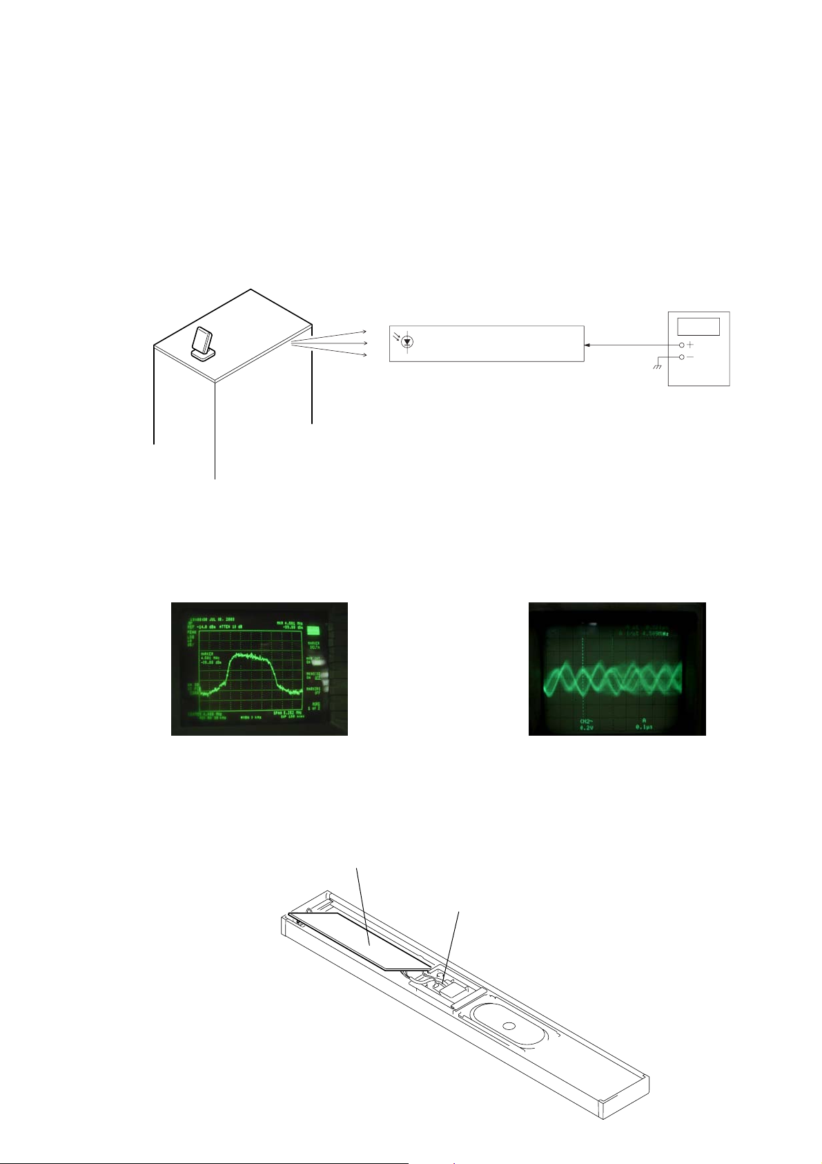
[AMP Board Input Signal Check Procedure]
SA-TSLF1H/SS-CTLF1H/TSLF1H/TSLF1HW
SECTION 1
Note 1: Connect the SA-WSLF1H to the HCD-LF1H. Set up the system so that the infrared signal from IR transmitter (DIR-T1) can be received by the
Note 2: The IR status indicator of this unit (SA-TSLF1H) lights in red when the power of the SA-WSLF1H receiving waiting state (when data is not
rear speaker (SA-TSLF1H).
transmitted.) When the power of the SA-WSLF1H is turned on and the infrared signal from IR transmitter (DIR-T1) is received by this unit (SATSLF1H), the IR status indicator of this unit (SA-TSLF1H) lights in green.
Check procedure:
1. Connect a spectrum analyzer and an oscilloscope to the connector CN7301 pin-1 of DIAT PD board.
IR transmitter
(DIR-T1)
Infrared
Transmission
IR receiver diode (D7301-D7304)
DIAT PD board
CN7301
Spectrum analyzer
or Oscilloscope
1
pin
* In the case of DIR-R3 is connected, the connector CN7301 pin-1 of
DIAT PD board is checked.
Subwoofer
(SA-WSLF1H)
2. Confirm that the spectrum is displayed as shown in Fig. 1 on spectrum analyzer. Also confirm that the waveform as shown in Fig. 2
is displayed.
4.5MHz
↓
Fig. 1 Fig. 2
• SERVICING POSITION (DIAT AMP BOARD)
Refer to figure, and inspect the DIAT AMP board.
DIAT AMP
board
SPK JACK
board
3
SA-TSLF1H/SS-CTLF1H/TSLF1H/TSLF1HW
Ver. 1.1
The units that are required for the system operation check during repair service
Unit to be
checked
Unit
required for checking
DVD player:
HCD-LF1H
Subwoofer:
SA-WSLF1H
Front speaker:
SS-TSLF1H
Center speaker:
SS-CTLF1H
Surround speaker (L):
SA-TSLF1H
AC adaptor:
AC-LF1HR
Surround speaker (R):
SS-TSLF1HW
Remote commander:
RM-ADP011
DVD player:
HCD-LF1H
*1 Only the defective unit.
Units with
a
mark: The units that are required for the system operation check during repair service.
(However, there can be a case that some units of the system need to not be brought into repair shop depending on the unit.that become defective.)
Subwoofer:
SA-WSLF1H
Front speaker:
SS-TSLF1H
*1
Center speaker:
SS-CTLF1H
Surround speaker
(L): SA-TSLF1H
AC adaptor:
AC-LF1HR
Surround speaker
(R): SS-TSLF1HW
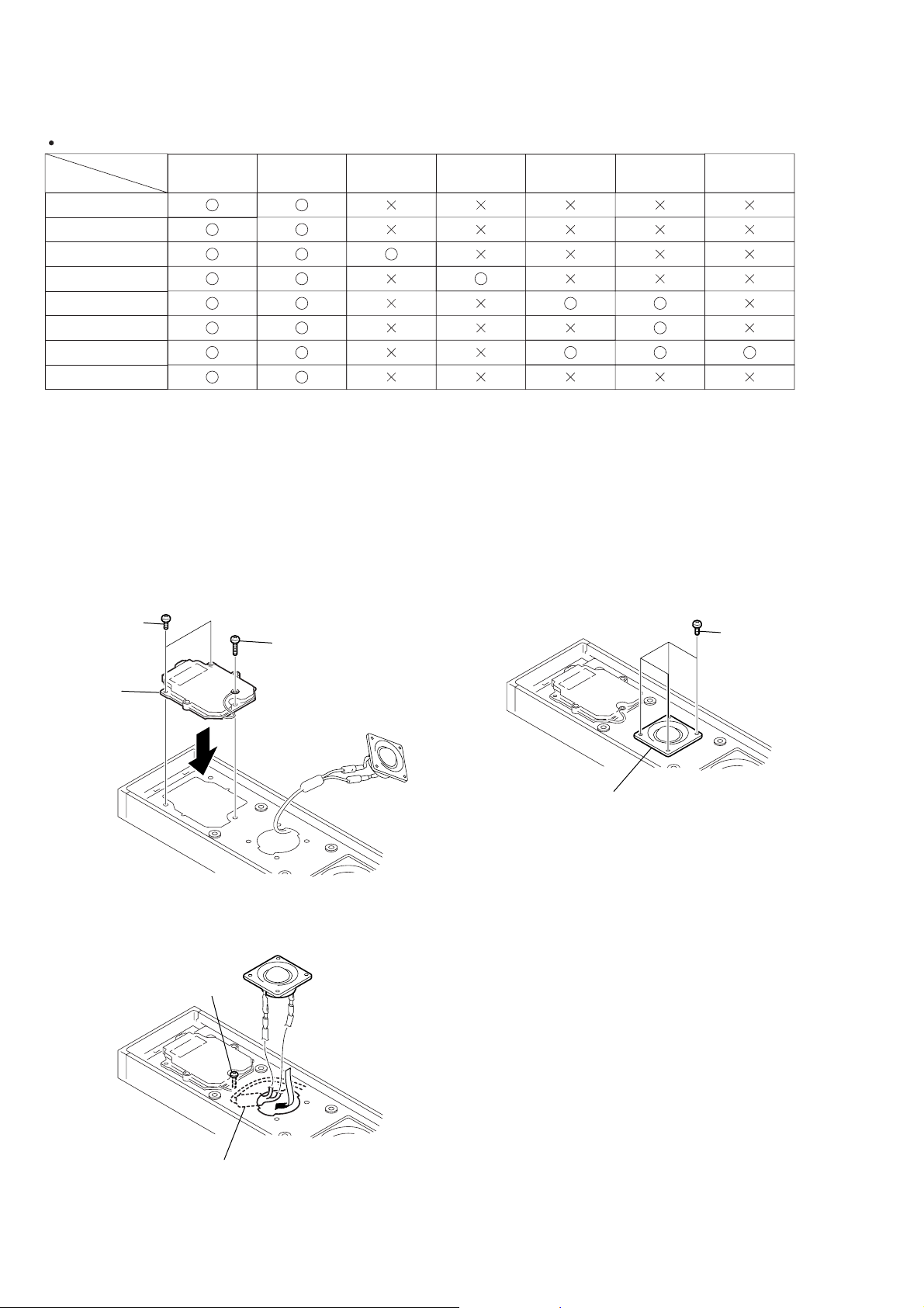
[Note on Assembling the SA-TSLF1H]
When assembling the PD block, be sure to follow the steps below.
Otherwise, the capacitor may break and a product failure may result.
1. Check that screw A is +BVTP3 × 14, and install the PD block
to the main unit.
two screws
(+BVTP 3
2. Take in the capacitor to the main unit.
×
10)
screw A
×
(+BVTP 3
14)
PD block
Check that the capacitor does not touch screw A inside the
main unit.
3. Install the LOUDSPEAKER (2.5 cm) (SP902) with the
+BVTP3 × 8 screw.
four screws
(+BVTP 3
LOUDSPEAKER (2.5cm) (SP902)
×
8)
screw A
capacitor
4
+
+
-
-
CN301 CN109 CN108 CN302
CN7301
CN310
CN311
CN307
CN305CN304
DIAT AMP
board
LED
board
DIAT PD
board
DIAT PD
board
SPK JACK
board
SPK JACK
board
RETAINER
board
CN308
loudspeaker
(7 × 12 cm) (SP901)
loudspeaker
(7 × 12 cm) (SP901)
loudspeaker
(2.5 cm) (SP902)
loudspeaker
(2.5 cm) (SP902)
DIAT AMP
board
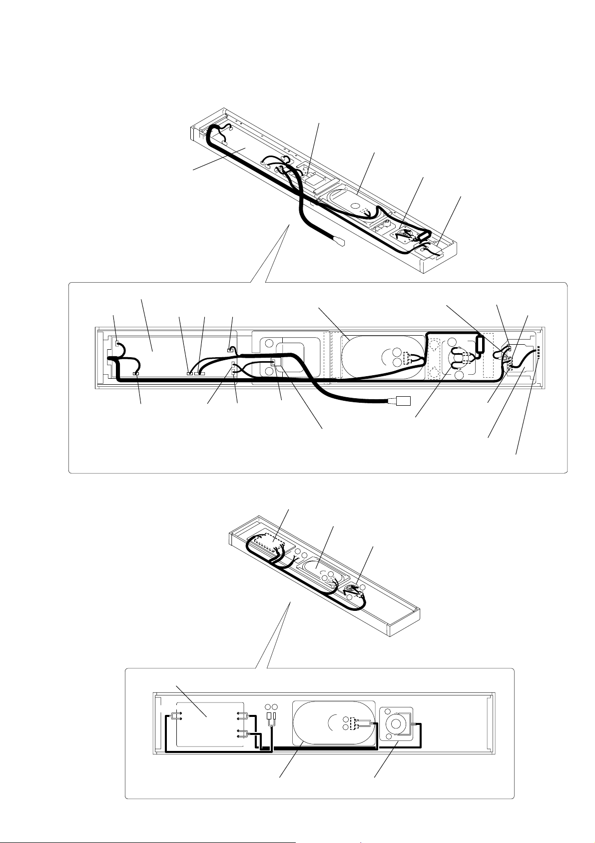
• CHART OF HARNESSES
• SA-TSLF1H
SA-TSLF1H/SS-CTLF1H/TSLF1H/TSLF1HW
• SS-CTLF1H
MOUNTED PC board
gray
+
IN
-
+
TW
-
-
WF
+
red
loudspeaker
MOUNTED PC board
+
-
-
+
blue
(7 × 12 cm) (SP901)
loudspeaker
-
+
loudspeaker
-
+
-
+
loudspeaker
(7 × 12 cm) (SP901)
(2.5 cm) (SP902)
-
+
(2.5 cm) (SP902)
5
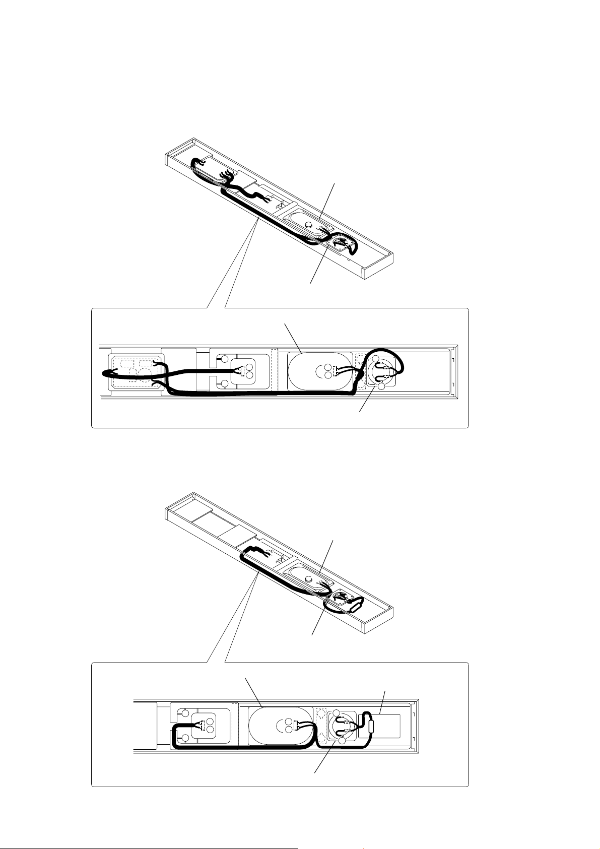
SA-TSLF1H/SS-CTLF1H/TSLF1H/TSLF1HW
• SS-TSLF1H
• SS-TSLF1HW
+
-
loudspeaker
loudspeaker
loudspeaker
(7 × 12 cm) (SP901)
(2.5 cm) (SP902)
(7 × 12 cm) (SP901)
+
+
-
loudspeaker
(2.5 cm) (SP902)
+
-
loudspeaker
loudspeaker
loudspeaker
(7 × 12 cm) (SP901)
+
+
-
loudspeaker
(7 × 12 cm) (SP901)
(2.5 cm) (SP902)
acoustic material
(2.5 cm) (SP902)
6
SA-TSLF1H/SS-CTLF1H/TSLF1H/TSLF1HW
SECTION 2
GENERAL
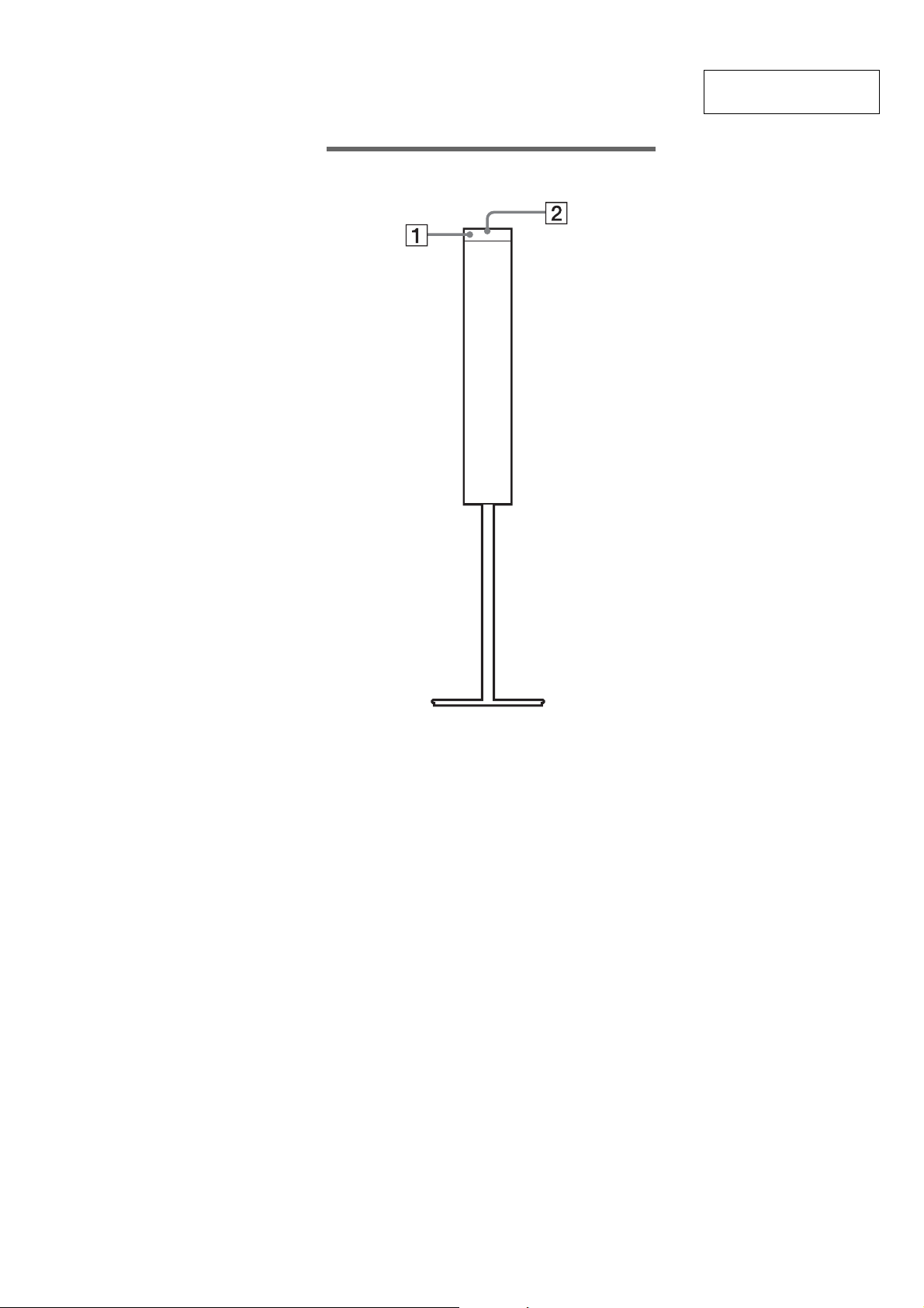
Surround sp eaker (L)
This section is extracted
from instruction manual.
A IR receiver (29)
B IR status indicator (29)
7
SA-TSLF1H/SS-CTLF1H/TSLF1H/TSLF1HW
Ver. 1.1
SECTION 3
DISASSEMBLY (SA-TSLF1H)
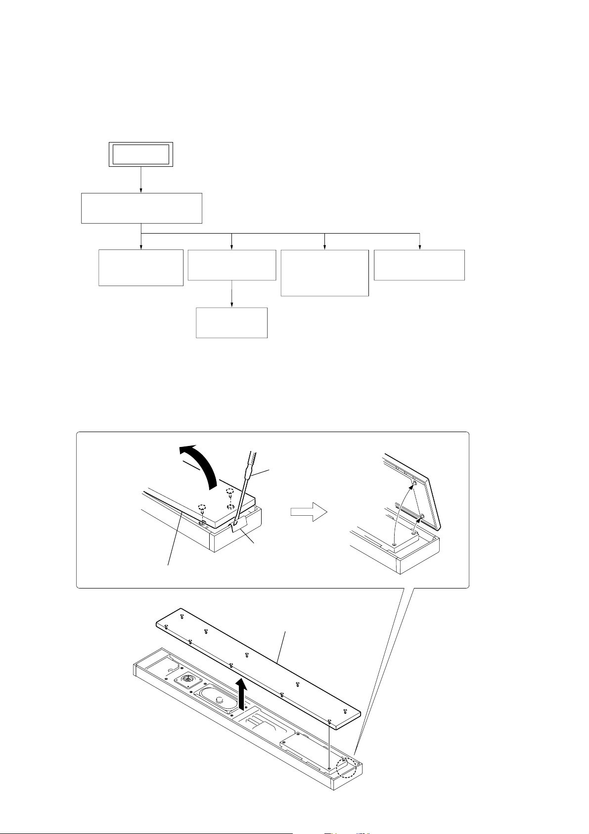
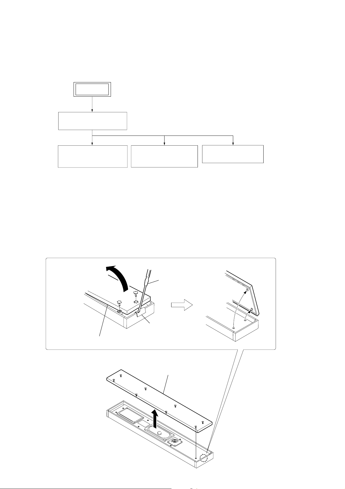
3-1. DISASSEMBLY FLOW
•This set can be disassembled in the order shown below.
SET
3-2. GRILLE FRAME (A) ASSY
Note: Follow the disassembly procedure in the numerical order given.
(Page 8)
3-3. LOUDSPEAKER
(7 × 12 cm) (SP901)
(Page 9)
3-4. BRACKET (A)
TERMINAL (Page 9)
3-7. PARTITION
(Page 11)
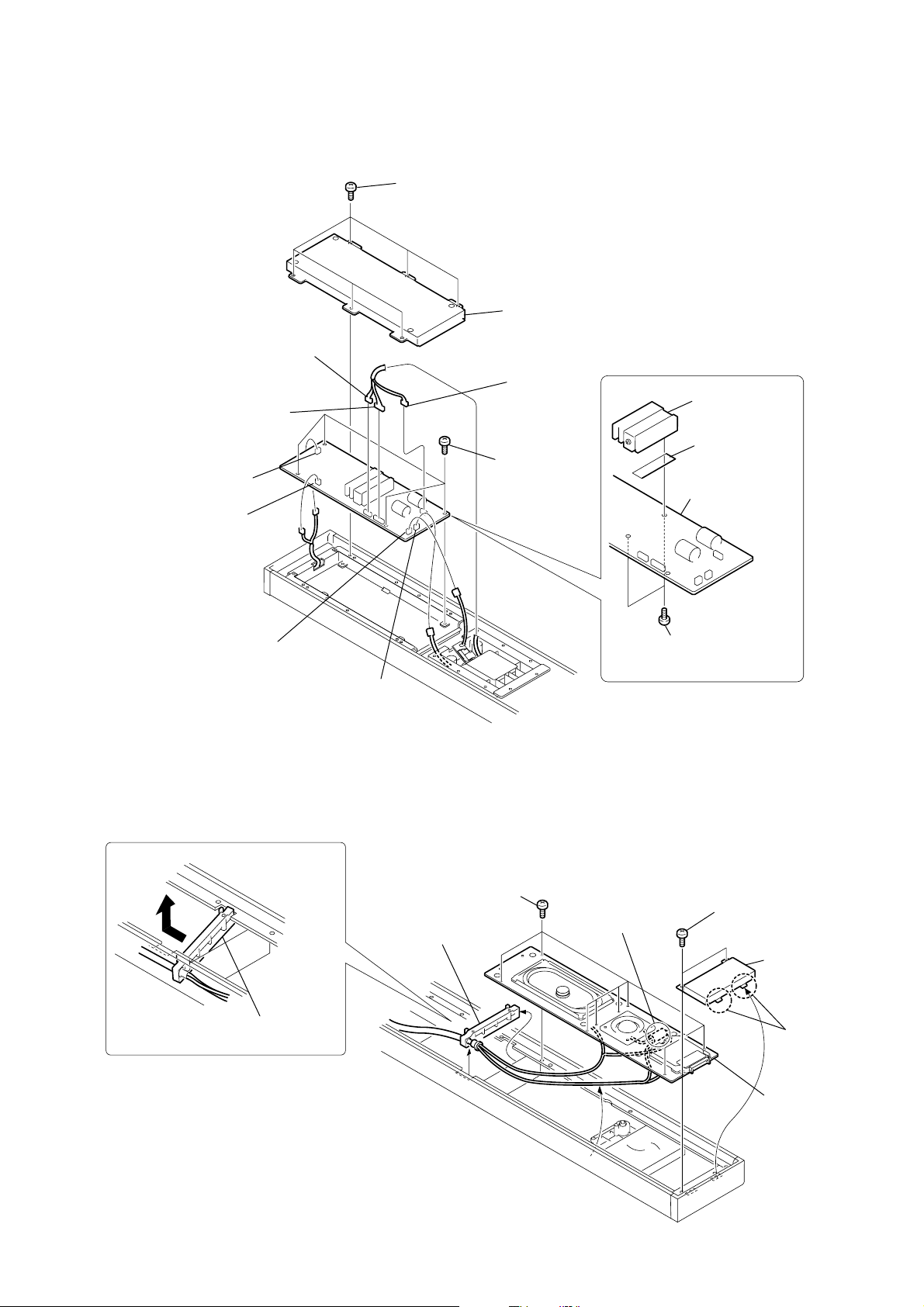
3-2. GRILLE FRAME (A) ASSY
A
3-5. LOUDSPEAKER
(2.5 cm) (SP902),
DIAT PD BOARD
(Page 10)
driver
3-6. DIAT AMP BOARD
(Page 11)
cushion
1
Remove the grille frame (A) assy in the direction of the arrow A.
2
grille frame (A) assy
8
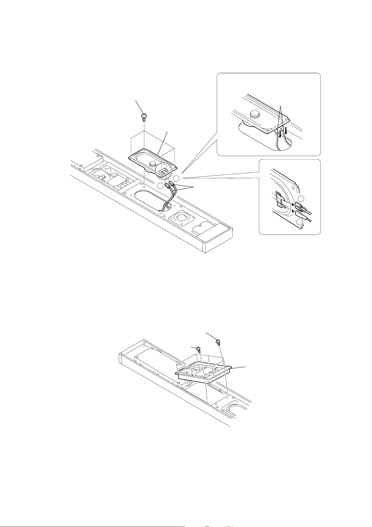
3-3. LOUDSPEAKER (7 x 12 cm) (SP901)
1
four
screws
(+BVTP 3
×
10)
+
SA-TSLF1H/SS-CTLF1H/TSLF1H/TSLF1HW
3
loudspeaker
(7 × 12 cm)
(SP901)
-
2
harnesses
Ver. 1.1
Bend down the terminals before installation
as shown in the figure.
terminals
3-4. BRACKET (A) TERMINAL
2
six
screws
(+BVTP 3 × 10)
1
two
screws
(+BVTP 3 × 14)
3
bracket (A) terminal
+
-
9
SA-TSLF1H/SS-CTLF1H/TSLF1H/TSLF1HW
Ver. 1.1
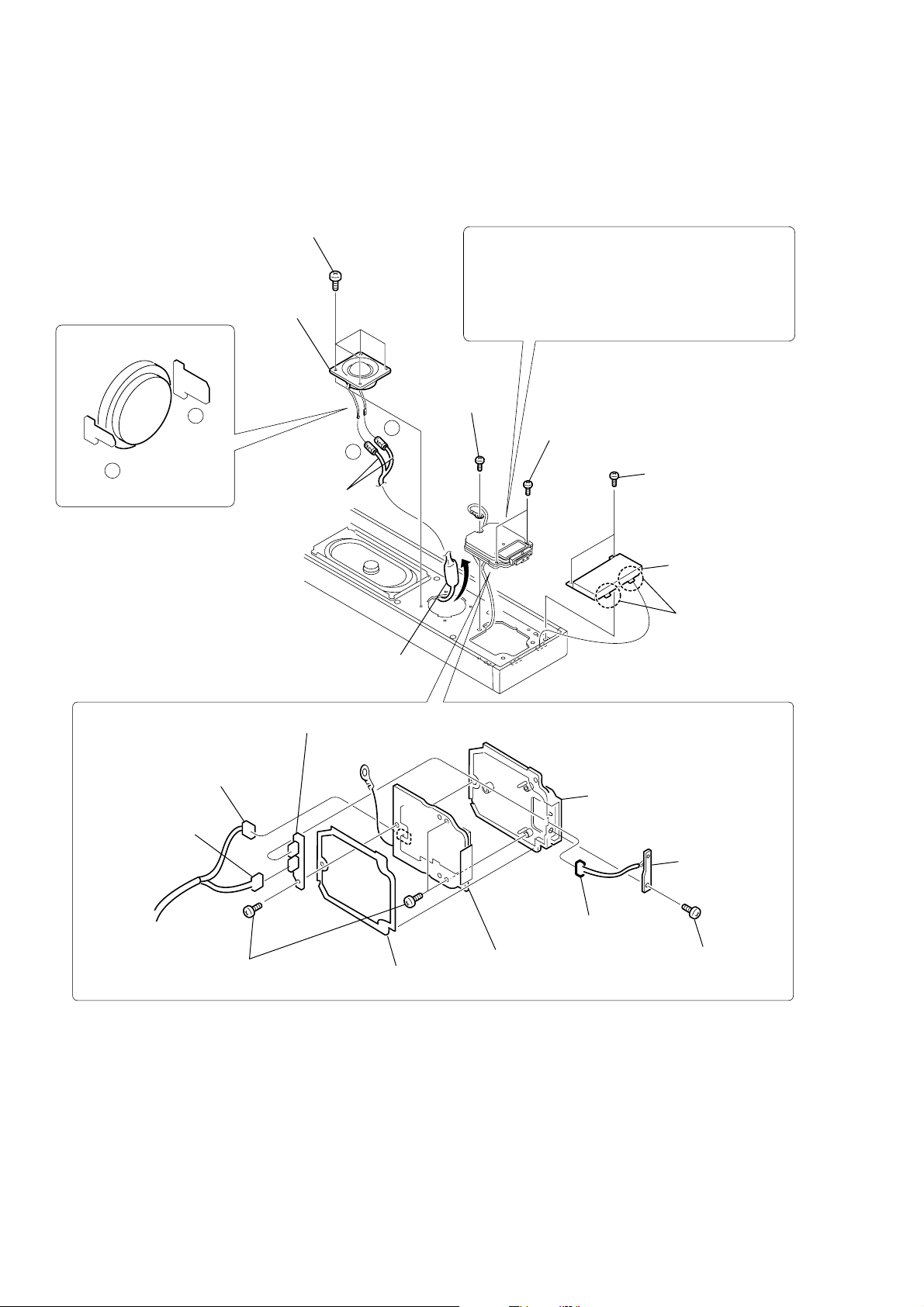
3-5. LOUDSPEAKER (2.5 cm) (SP902), DIAT PD BOARD
1
four screws
(+BVTP 3
4
loudspeaker
(2.5 cm)
(SP902)
+
–
3
2
×
8)
+
–
harnesses
Take out the capacitor.
8
PRECAUTION DURING PD BLOCK REMOVING
When removing the PD block, be sure to remove the
LOUDSPEAKER (2.5 cm) (SP902), and take the
capacitor out of the main unit.
The capacitor may break if the PD block is not properly
assembled. Be sure to refer to [Note on Assembling
the SA-TSLF1H] in the Service Note.
screw
(+BVTP 3
×
14)
9
two screws
(+BVTP 3
×
10)
5
two screws
(+BVTP 3
7
6
PD window assy
two claws
×
10)
qg
connector
(CN310)
qf
connector
(CN7301)
qh
three screws
(+BVTP 3
×
qj
10)
RETAINER board
q;
PD cushion
ql
DIAT PD board
qk
qs
connector
(CN311)
PD bracket
qd
LED board
qa
screw
(+BVTP 3
×
10)
10
3-6. DIAT AMP BOARD
3
connector
(CN109)
4
connector
(CN108)
6
connector
(CN301)
7
connector
(CN308)
1
six
screws
(+BVTP 3
SA-TSLF1H/SS-CTLF1H/TSLF1H/TSLF1HW
×
10)
amp cover
2
5
connector
(CN302)
0
four
screws
(+BVTP 3
×
6)
qs
qd
qf
DIAT AMP board
8
3-7. P ARTITION
6
Remove the partition in
the direction of the arrow.
connector
(CN305)
9
connector
(CN304)
4
eight
7
screws
partition
(+BVTP 3 × 10)
qa
Attention the position
of capacitor.
two
screws
(+BVTP 3
1
(+BVTP 3
×
two
6)
screws
×
10)
3
PD window assy
2
two claws
5
baffle board (A)
11
SA-TSLF1H/SS-CTLF1H/TSLF1H/TSLF1HW
SECTION 4
DISASSEMBLY (SS-CTLF1H)
4-1. DISASSEMBLY FLOW
•This set can be disassembled in the order shown below.
SET
4-2. GRILLE FRAME (C) ASSY
4-3. LOUDSPEAKER
Note: Follow the disassembly procedure in the numerical order given.
(Page 12)
(SP901)
(Page 13)
(7 × 12 cm)
4-4. LOUDSPEAKER
4-2. GRILLE FRAME (C) ASSY
A
(SP902)
(Page 13)
driver
(2.5 cm)
4-5. MOUNTED PC BOARD
(Page 14)
12
cushion
1
Remove the grille frame (C) assy in the direction of the arrow A.
2
grille frame (C) assy
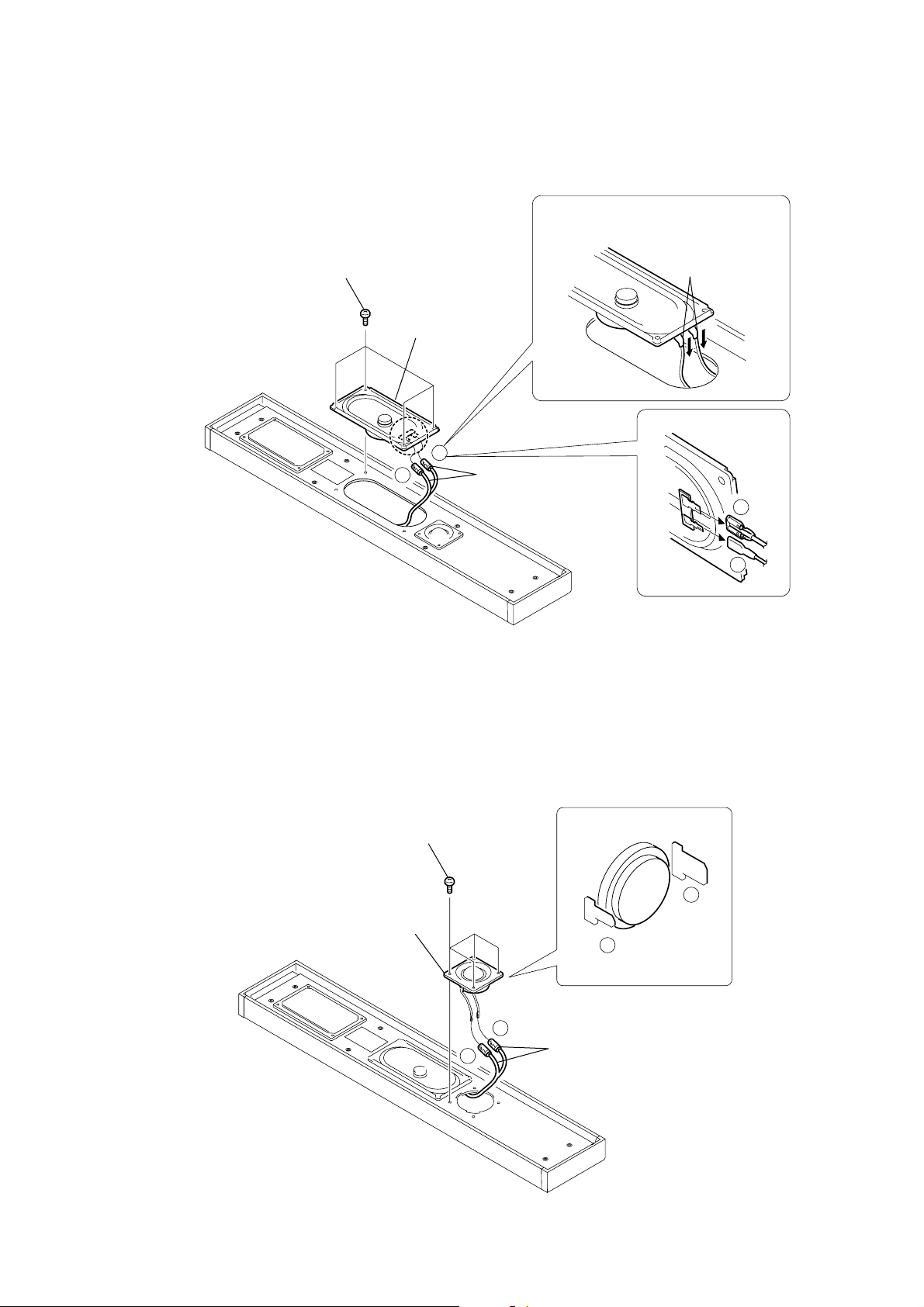
4-3. LOUDSPEAKER (7 x 12 cm) (SP901)
1
four
screws
(+BVTP 3
×
10)
3
+
SA-TSLF1H/SS-CTLF1H/TSLF1H/TSLF1HW
Bend down the terminals before installation
as shown in the figure.
terminals
loudspeaker
(7 × 12 cm)
(SP901)
-
2
harnesses
4-4. LOUDSPEAKER (2.5 cm) (SP902)
1
3
loudspeaker
(2.5 cm)
(SP902)
four
screws
(+BVTP 3 × 10)
+
-
+
-
+
2
-
harnesses
13
SA-TSLF1H/SS-CTLF1H/TSLF1H/TSLF1HW
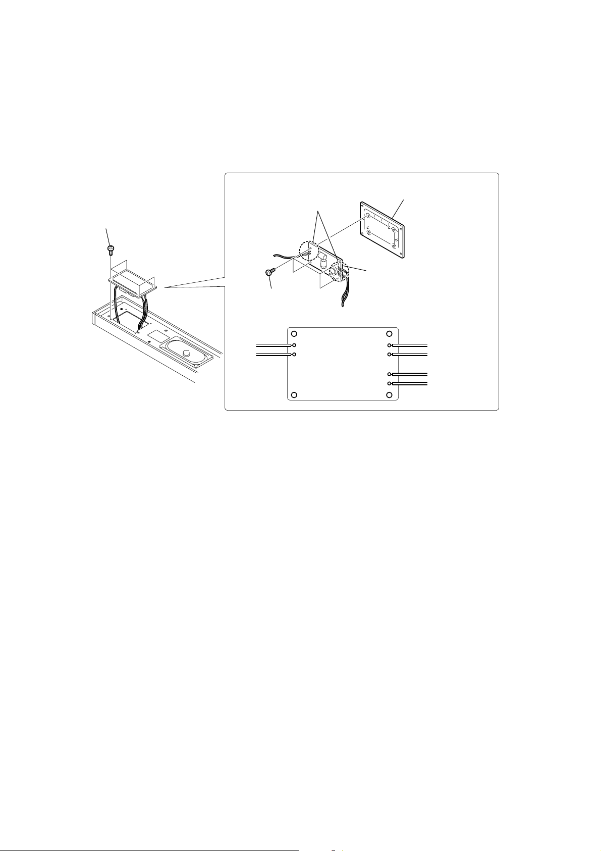
4-5. MOUNTED PC BOARD
1
four
screws
(+BVTP 3
×
10)
2
f
our
screws
(+BVTP 3
4
Remove soldering from
the six points.
×
8)
3
network bracket
5
mounted pc board
gray
+
IN
-
TW
WF
+
blue
-
-
+
red
14
 Loading...