

Page 1
Printed in Japan
4K Digital Projector
SRX-T423
4-547-935-01 (1)
© 2014 Sony Corporation
取扱説明書 JP
Operating Instructions _____ GB
お買い上げいただきありがとうございます。
電気製品は安全のための注意事項を守らないと、
火災や人身事故になることがあります。
この取扱説明書には、事故を防ぐための重要な注意事項と製品の取り扱いかたを示してあります。
この取扱説明書をよくお読みのうえ、製品を安全にお使いください。お読みになったあとは、
いつでも見られるところに必ず保管してください。
Page 2
日本語
安全のために
ソニー製品は安全に充分配慮して設計されています。しかし、電気製品はまち
がった使いかたをすると、火災や感電などにより死亡や大けがなど人身事故につ
ながることがあり、危険です。
事故を防ぐために次のことを必ずお守りください。
安全のための注意事項を守る
4 ページから 5 ページの注意事項をよくお読みください。
警告表示の意味
取扱説明書および製品では、次の
ような表示をしています。表示の
内容をよく理解してから本文をお
読みください。
定期点検を実施する
1 年に一度は、内部の点検をお買い上げ店またはソニーのサービス窓口にご依頼
ください(有料)。
故障したら使わない
すぐにソニーのお買い上げ店またはソニーのサービス窓口にご連絡ください。
万一、異常が起きたら
• 煙が出たら
• 異常な音、においがしたら
• 内部に水、異物が入ったら
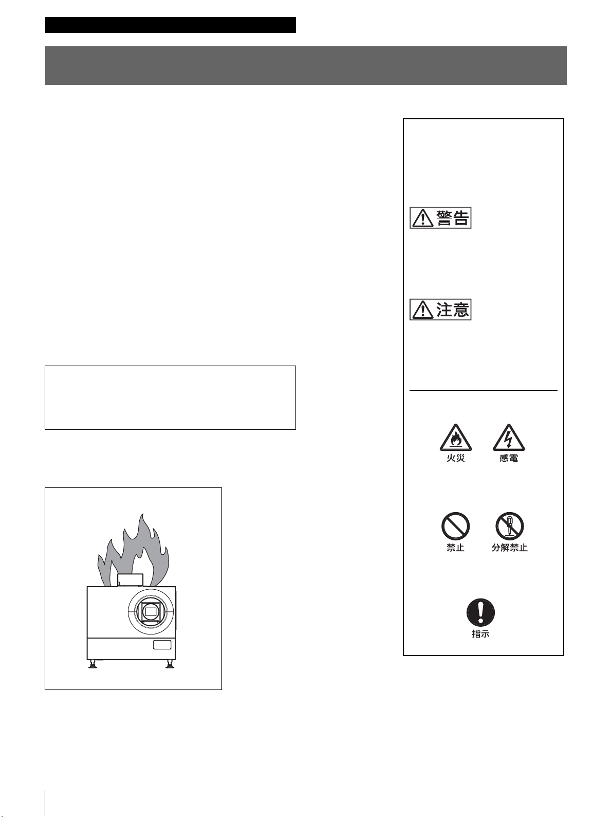
• 製品を落としたりキャビネットを破損したときは
m
a 電源スイッチで電源を切る。
b ソニーのお買い上げ店またはソニーのサービス窓口に連絡する。
炎が出たら
この表示の注意事項を守らないと、
火災や感電などにより死亡や大け
がなど人身事故につながることが
あります。
この表示の注意事項を守らないと、
感電やその他の事故によりけがを
したり周辺の物品に損害を与えた
りすることがあります。
注意を促す記号
行為を禁止する記号
m
すぐに電源を切り、消火する。
2
行為を指示する記号
Page 3
目次警告 5
第 4 章 SRXController で行う調整
と設定
警告 .....................................................................................4
注意 .....................................................................................5
3D 映像の視聴についての安全上のご注意 ..........................5
使用上のご注意........................................................................ 6
第 1 章 概要
各部の名称と働き....................................................................7
本体 ............................................................................................................... 7
ControlFunctionMenu(コントロールファンク
ションメニュー)画面................................................... 8
第 2 章 準備
設置・使用時のご注意.........................................................11
設置に適さない場所 .......................................................................11
使用に適さない状態 .......................................................................12
SRXController をコントロール用 PC にインストール
する............................................................................12
動作環境 ..................................................................................................12
SRXController をインストールする.................................13
コントロール用 PC を接続する .........................................14
イーサネットケーブルで接続する.......................................14
RS-232C 端子に接続する.............................................................15
SRXController を起動する .............................................15
プロジェクターの主電源を入れる.......................................15
SRXController を起動する.......................................................15
接続モードを変更する..................................................................16
投影する機器を接続する .....................................................17
PC を接続する(DVI-D 接続)................................................17
HD-SDI 機器を接続する ..............................................................17
HDMI 機器を接続する .................................................................18
第 3 章 投影
コントロール画面を表示する .............................................22
PICTURECONTROL(ピクチャーコントロール)
画面............................................................................23
Board(インプットボード)......................................................23
InputSource(入力ソース).....................................................23
3DResolutionFormat
(3D 解像度フォーマット).........................................23
SignalInfo(信号情報)................................................................23
SignalAdjust(信号調整)..........................................................24
COLOR/FRAME(カラー/フレーム)画面..................24
Board(インプットボード)......................................................24
Color(カラー)...................................................................................24
FrameAdjust(フレーム調整).............................................25
INSTALLATION(設置設定)画面 ................................. 26
LENSCONTROL(レンズコントロール)....................26
ELECTRICSHIFTFUNCTION
(電気的シフト機能)......................................................26
IMAGEFLIP(映像反転).........................................................26
PROGRESSIVEDISPLAYMODE
(プログレッシブディスプレイモード)...........26
SQUEEZE(スクイーズ)...........................................................26
LAMPPOWER(ランプパワー).........................................27
TESTPATTERN(テストパターン)..............................27
SINGLE3DADJUST(シングル 3D 調整).................27
入力信号と調整・設定項目 .................................................27
第 5 章 その他
ランプ交換の目安................................................................. 28
故障かな?と思ったら.........................................................29
メッセージ ............................................................................ 30
エラーメッセージ.............................................................................30
情報メッセージ..................................................................................32
本機の性能を保持するために .............................................33
アフターサービス................................................................. 33
仕様........................................................................................ 34
索引........................................................................................ 36
JP
スクリーンに画像を映す .....................................................19
4K 信号を 4 画面モードで映す...............................................20
目次
3
Page 4
警告
規定の電源電圧で使用する
取扱説明書に記されている電源電圧
以外での使用は火災や感電の原因と
なります。
油煙、湯気、湿気、埃の多
い所で使用しない
上記のような場所や、取扱説明書に
記されている使用条件以外の環境で
使用すると、火災や感電の原因とな
ることがあります。
機器周囲温度を仕様に合う
ように制御する
排気口付近は触らない
排気口付近は、ランプの熱で温度が
高く、手などが触れるとやけどの原
因となります。
排気口、吸気口をふさがな
い
排気口、吸気口をふさぐと内部に熱
がこもり、火災や故障の原因となる
ことがあります。風通しをよくする
ために次の項目をお守りください。
• 密閉された狭い場所に押し込めな
い。
• 布などで包まない。
• 本機の下に布や紙を敷かない。
内部を開けない
内部には電圧の高い部分があり、
キャビネットを開けたり改造したり
すると、火災や感電の原因となるこ
とがあります。内部の調整や設定、
点検、修理はお買い上げ店またはソ
ニーのサービス窓口にご依頼くださ
い。
取扱説明書に記されている機器周囲
温度外で使用すると、ランプの破裂
や故障の原因となります。
製品の上にものを置かない
製品の上に重いものを置くと、落下
してけがをすることがあります。
レンズをのぞかない
投影中に本機のレンズをのぞくと光
が目に入り、悪影響を与えることが
あります。
レンズの前にものを置かな
い
レンズの前にものがあると火災の原
因となることがあります。
ランプはアラームが出たら、
交換する
ランプは劣化したまま使用すると、
ランプ破裂の原因となります。ラン
プ交換のアラームが出たら交換して
ください。
定期的に内部の掃除を依頼
する
長い間掃除をしないと内部にほこり
がたまり、火災や感電の原因となる
ことがあります。1 年に一度は、内部
の掃除をお買い上げ店またはソニー
のサービス窓口にご依頼ください
(有料)。
特に、湿気の多くなる梅雨の前に掃
除をすると、より効果的です。
4
警告
Page 5
注意
内部に水や異物を入れない
水や異物が入ると火災や感電の原因とな
ることがあります。
万一、水や異物が入ったときは、すぐに
電源を切り、お買い上げ店またはソニー
のサービス窓口にご相談ください。
製品の上に乗らない
倒れたり、落ちたりして、けがの原因と
なることがあります。
3D 映像の視聴についての
安全上のご注意
• 3D映像をご覧になる以外は 3D メガネを使用しないでく
ださい。
• ソニーが認証した 3D メガネ以外は使用しないでくださ
い。
• 3D 映像の視聴中に、眼の疲労、疲れ、気分が悪くなるな
どの不快な症状が出ることがあります。視聴中に体調不
良を感じた場合には、ご自身で判断し、すぐに視聴を中
止してください。不快な症状がでたときは、回復するま
で 3D 映像の視聴をやめ、必要に応じて医師にご相談く
ださい。
• お子様(特に 6 歳未満の子)の視覚は発達段階にありま
す。お子様が 3D 映像を視聴する前に小児科や眼科など
の医師にご相談ください。
• 大人の監視がない場合、お子様だけのご視聴はなさらな
いでください。
• 3D 映像を上映・提供される場合は、上記注意点を守るよ
う監督してください。
注意/3D 映像の視聴についての安全上のご注意
5
Page 6
使用上のご注意
結露について
プロジェクターを設置している室内の急激な温度変化およ
び、寒いところから急に暖かい場所へ持ち込んだときなど
は結露を引き起こすことがあります。
結露は故障の原因となりますので、冷暖房の温度調節には
ご注意ください。
結露が起きたときは、プロジェクターの電源を入れたまま
約 2 時間放置した後でお使いください。
液晶プロジェクターについて
液晶プロジェクターは非常に精密度の高い技術で作られて
いますが、黒い点が現われたり、赤と青、緑の点が消えな
かったりすることがあります。また、すじ状の色むらや明
るさのむらが見える場合もあります。これらは、プロジェ
クターの構造によるもので、故障ではありません。また、
複数台の液晶プロジェクターを並べてスクリーンへ投写す
る場合、プロジェクターごとに色合いのバランスが異なる
ため、同一機種の組み合わせであってもそれぞれ色合いの
違いが目立つ場合があります。
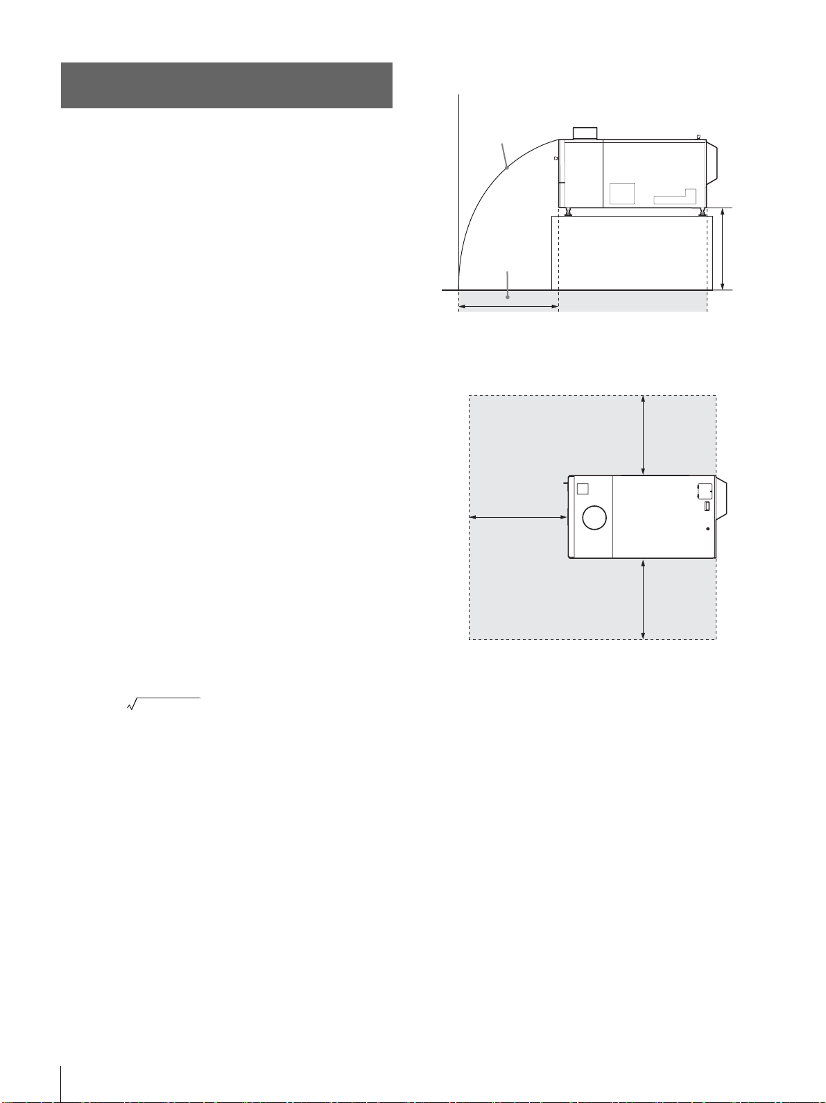
連続点灯の禁止
左側面図
ランプ破裂時の
飛散放物線
ランプ破裂時
の危険ゾーン
x
上面図
ランプ破裂時の危険ゾーン
x
y
床
x
キセノンランプは 24 時間連続駆動をすると、寿命が短くな
ります(約半分)。必ず、1 時間以上消灯してください。
ランプ破裂時の立ち入り禁止
万一、ランプが破裂した場合、下図に示したゾーンは危険
ですので近づかないでください。
危険ゾーン(x)は、床からプロジェクター底面までの高さ
(y)によって変わります。
x=20/3 ×10y+6400
例えば、床からプロジェクター底面までの高さ(y)が 800
mm の場合、上の計算式で出した値に基づいた危険ゾーン
(x)は 800mm になります。
x
使用上のご注意
6
Page 7
第 1 章 概要
概要
各部の名称と働き
本体
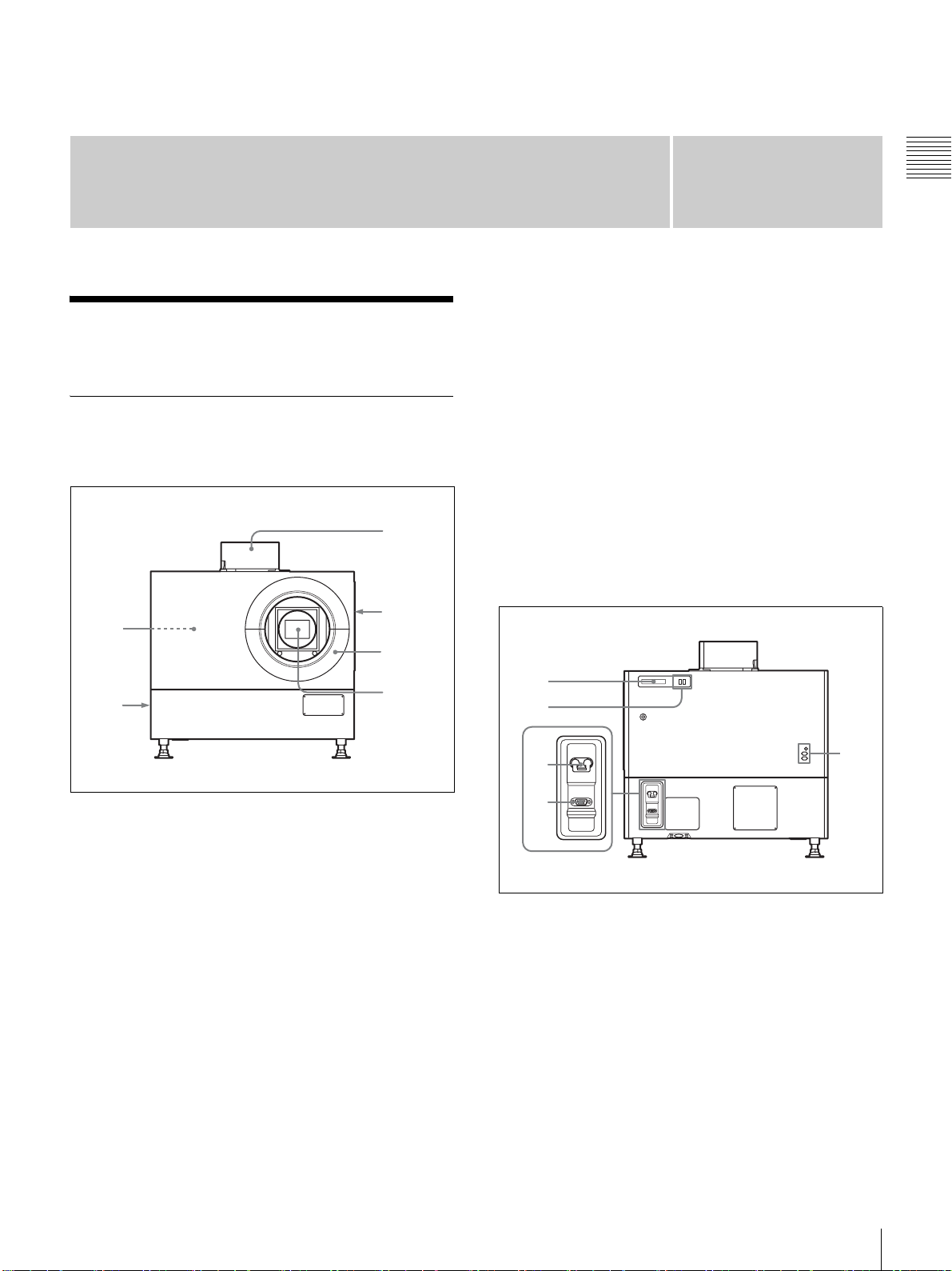
前面/側面
5
1
2
3
1
第章
右から順に INPUTA、INPUTB、INPUTC、INPUTD と
なります。
標準装備として INPUTA に HDCPDVI ボード LKRI-005
が装着されています。用途に応じて別のインプットボード
に差し換えることもできます。
DVI-D 端子(DVI コネクター 24 ピン、凸):プログレッシ
ブの DVI 信号および HDCP 対応の DVI 信号を入力します。
AUX 端子(DVI コネクター 24 ピン、凸):拡張信号入力用
です。対応機器については、お買い上げ店またはソニーの
サービス窓口にお問い合わせください。
f 排気口(左側面)
後面
6
a 排気口(上面)
b 吸気口/エアフィルター(右側面)
エアフィルターの交換については、お買い上げ店またはソ
ニーのサービス窓口にお問い合わせください。
c レンズカバー
d レンズ取り付け部
別売のレンズを取り付けるときは、お買い上げ店またはソ
ニーのサービス窓口にお問い合わせください。
e インプットボード取り付け部(本体内部)
用途に応じ、別売のインプットボードを取り付けます。取
り付けるときは、お買い上げ店またはソニーのサービス窓
口にお問い合わせください。
4
1
2
3
RS-232C
4
a STATUSMESSAGE(ステータスメッセージ)表示
窓
各種メッセージを表示します。
◆ メッセージの詳細については、30 ページをご覧ください。
b ステータスインジケーター
MAIN(メイン)インジケータと LAMP(ランプ)インジ
ケータの組み合わせにより、以下の状態を表示します。
5
各部の名称と働き
7
Page 8
MAIN
1
6
2 3 4
67
インジケータ
●(赤) ●(赤) スタンバイ状態。SRXController
第 1 章 概要
●(緑) ●(緑) SRXController で電源を入りにし
(緑) (緑) SRXController で電源を切りにし
LAMP
インジケータ
本機の状態
(SRX コントローラー)で本機の電
源を入れることができる。
た。SRXController で本機の操作
ができる。
てスタンバイ状態にした。クーリ
ング中。
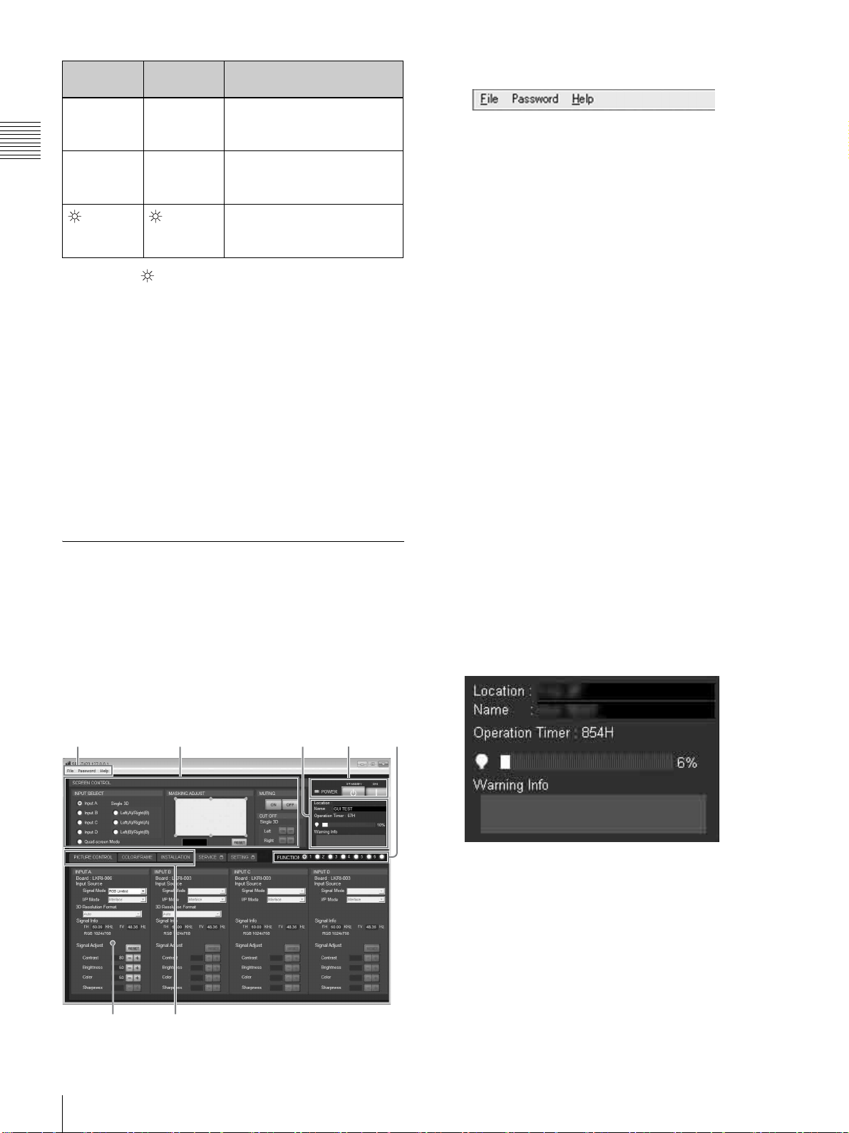
a メニューバー
File(ファイル)メニュー
File メニューから [Quit] を選択すると、SRXController を
終了します。
SaveLog(セーブログ):サービス用です。
詳しくは、ソニーのお買い上げ店またはサービス窓口
にお問い合わせください。
●:点灯 :点滅
c 電源スイッチ
プロジェクターの主電源をオン(?)/オフ(a)します。
d RS-232C 端子(D-sub9 ピン、凹)
付属の SRXController(SRX コントローラー)をインス
トールした PC のコネクターと接続します。PC から本機を
操作できます。
e ランプ調整窓
ランプを交換した後などに、ランプ位置を微調整するため
の窓です。調整は、お買い上げ店またはソニーのサービス
窓口にお問い合わせください。
ControlFunctionMenu(コント
ロールファンクションメニュー)画面
SRXController(SRX コントローラー)を PC にインス
トールすると、本機の操作を PC の画面で行うことができ
ます。ここでは、スクリーンに画像を投影するために表示
する画面について説明します。画質の調整や設定の変更を
行う画面については、「SRXController で行う調整と設定」
(22 ページ)をご覧ください。
Password(パスワード)メニュー
プロジェクターの設定を行う「SETTING(設定)」画面や、
サービス担当者が調整を行う「SERVICE(サービス)」画
面を表示する際に必要な認証用パスワードをリセットしま
す。
このメニューは、お使いの PC で Administrator(管理者)
権限を持つユーザーが SRXController を起動した場合のみ
表示されます。
◆「SETTING(設定)」画面、「SERVICE(サービス)」画面につ
いて詳しくは、特約店様用設置説明書をご覧ください。
Help(ヘルプ)メニュー
SRXController のバージョン情報および本機のシリアル番
号を表示します。
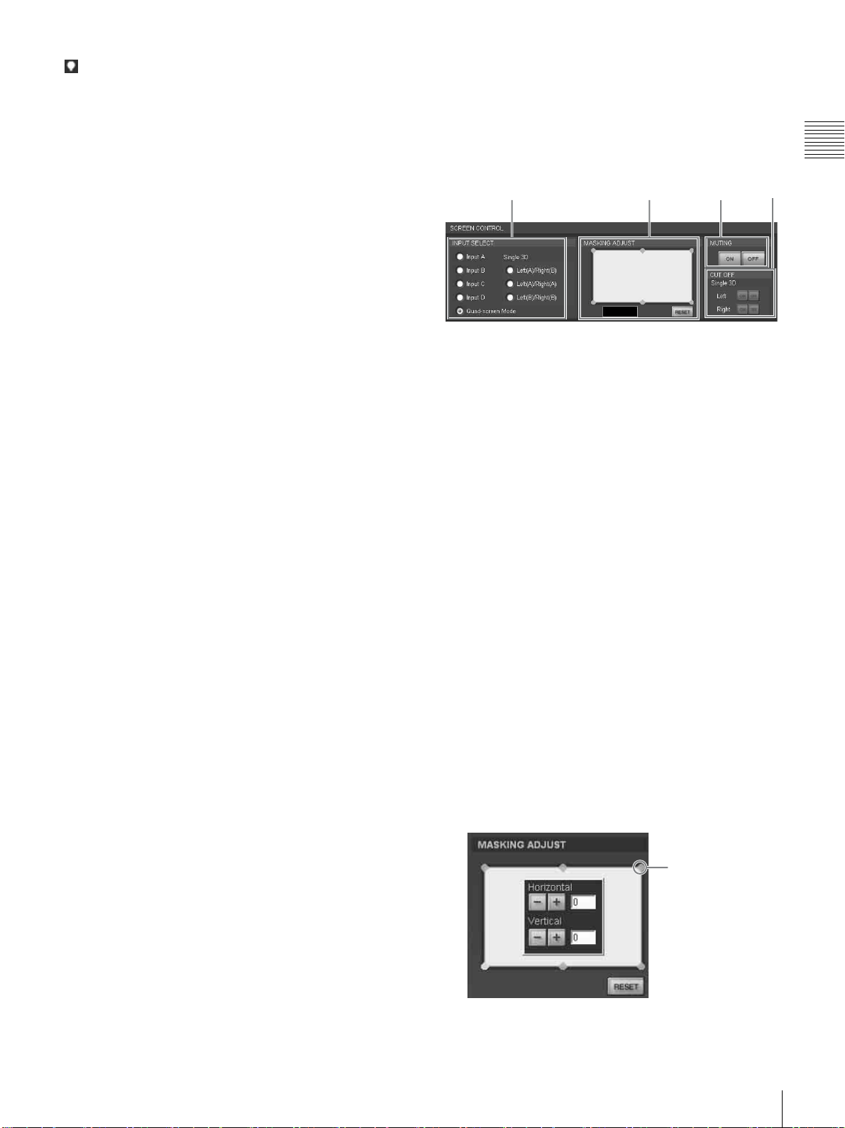
b SCREENCONTROL(スクリーンコントロール画面)
◆ 詳しくは「SCREENCONTROL(スクリーンコントロール)画
面」(9 ページ)をご覧ください。
c 情報表示部
1
各部の名称と働き
8
2345
Location:「SETTING(設定)」画面で入力した本機の設
置場所が表示されます。
Name:「SETTING(設定)」画面で入力した本機の名前が
表示されます。
OperationTimer:プロジェクターの累積使用時間(H)が
表示されます。
Page 9
(ランプ)インジケーター:ランプの推奨使用時間に対
1 2 4 5
する現在の使用時間の割合をバーと数値(%)で表示
します。
WarningInfo:本機に不具合が生じた場合、エラーメッ
セージを表示します。本体後面の STATUSMESSAGE
表示窓にも同じエラーメッセージが表示されます。
g 画面切り換えボタン
調整・設定したい項目に応じて画面を切り換えます。
SCREENCONTROL(スクリーンコント
ロール)画面
第 1 章 概要
d POWERON/STANDBY(?/1)(電源入/スタンバ
イ)ボタンと POWER インジケーター
本機後面の MAIN インジケーターと LAMP インジケー
ターが赤く点灯しているとき、[ON] ボタンをクリックする
と電源が入ります。両方のインジケーターと PC 画面の
POWER インジケーターが緑色に点灯し、PC 画面で本機の
操作ができます。
電源を切るときは、[STANDBY] ボタンをクリックし、表示
される確認画面で [OK] ボタンをクリックします。本機がス
タンバイ状態になり、本体のインジケーターと POWER イ
ンジケーターが点滅します。スタンバイ状態になっても本
体内部の温度を下げるためファンが回り続けます。ファン
が止まると MAIN インジケーターと LAMP インジケー
ターが赤く点灯します。
e FUNCTION(ファンクション)1 〜 7 ラジオボタン
SRXController の画面で調整・設定した内容をこれらのボ
タンに登録し、あとで登録した設定内容で投影することが
できます。
登録できる設定項目は以下のとおりです。
•「SCREENCONTROL」画面の [INPUTSELECT]、
[MASKINGADJUST] および [CUTOFF] の設定
•「PICTURECONTROL」画面の [InputSource] と [Signal
Adjust] の設定
•「COLOR/FRAME」画面の [Color] の設定
•「INSTALLATION」画面の [ELECTRICVSHIFT
FUNCTION]、[ELECTRICHSHIFTFUNCTION]、
[SQUEEZE]、[PROGRESSIVEDISPLAYMODE]、
[LAMPPOWER] の各項目、ズーム/フォーカスメモ
リー機能付きレンズ装着時の [LENSCONTROL] の設定、
および 3D 画像投影時の [SINGLE3DADJUST] の [3D
GammaSelect] と [PositionAdjust] の設定
◆ 詳しくは、22 ページをご覧ください。
123 4
a INPUTSELECT(入力信号選択)ラジオボタン
スクリーンに投影したい入力信号を選びます。
InputA:INPUTA に装着されたインプットボード(標準
装備)の端子に接続した機器からの映像を映すとき
InputB:INPUTB に装着されたインプットボード(別売)
の端子に接続した機器からの映像を映すとき
InputC:INPUTC に装着されたインプットボード(別売)
の端子に接続した機器からの映像を映すとき
InputD:INPUTD に装着されたインプットボード(別売)
の端子に接続した機器からの映像を映すとき
Quad-screenMode(4 画面モード):INPUTA 〜 D に装
着されたインプットボードからの各入力信号を 1 画面
に映すとき
Single3D ラジオボタン:3D 画像を映すときに使用しま
す。詳しくは、お買い上げ店またはソニーのサービス
窓口にお問い合わせください
b MASKINGADJUST(マスキング調整)部
スクリーンに合わせて映像の不要な部分に黒いマスキング
をすることができます。
6 か所の調整ポイントそれぞれで調整できます。
1 調整ポイントのひとつをダブルクリックする。
調整画面が表示されます。
f 調整・設定画面
画面切り換えボタンをクリックすると、それぞれの画面が
表示されます。「PICTURECONTROL(ピクチャーコント
ロール)」画面、「COLOR/FRAME(カラー/フレーム)」
画面、「INSTALLATION(設置設定)」画面が表示されま
す。
◆ それぞれの画面について詳しくは、「SRXController で行う調整
と設定」(22 ページ)をご覧ください。
調整ポイント
各部の名称と働き
9
Page 10
2 [Horizontal](水平)、[Vertical](垂直)の または
ボタンをクリックするか右のテキストボックスに数
値を入力し、画面を見ながら調節する。
設定範囲は、四隅の調整ポイントが 0 〜 950、まん中
第 1 章 概要
の調整ポイントが− 500 〜 500 です。
3 各調整ポイントについて、1、2 を繰り返して映像にマ
スキングを行う。
[RESET] ボタンを押すと、すべての調整値が工場出荷時の
値にリセットされます。
c MUTING(ミューティング)ON/OFF ボタン
[ON] ボタンをクリックすると、スクリーンの投影画像全体
が一時的に消えます。[OFF]ボタンをクリックすると、
映像が表示されます。
ミューティング機能は、シャッターを併用して光を完全に
遮断し、黒画面を表示します。
d CUTOFF(カットオフ)ON/OFF ボタン
3D 画像を映すときに使用します。詳しくは、お買い上げ店
またはソニーのサービス窓口にお問い合わせください。
10
各部の名称と働き
Page 11
準備
設置・使用時のご注意
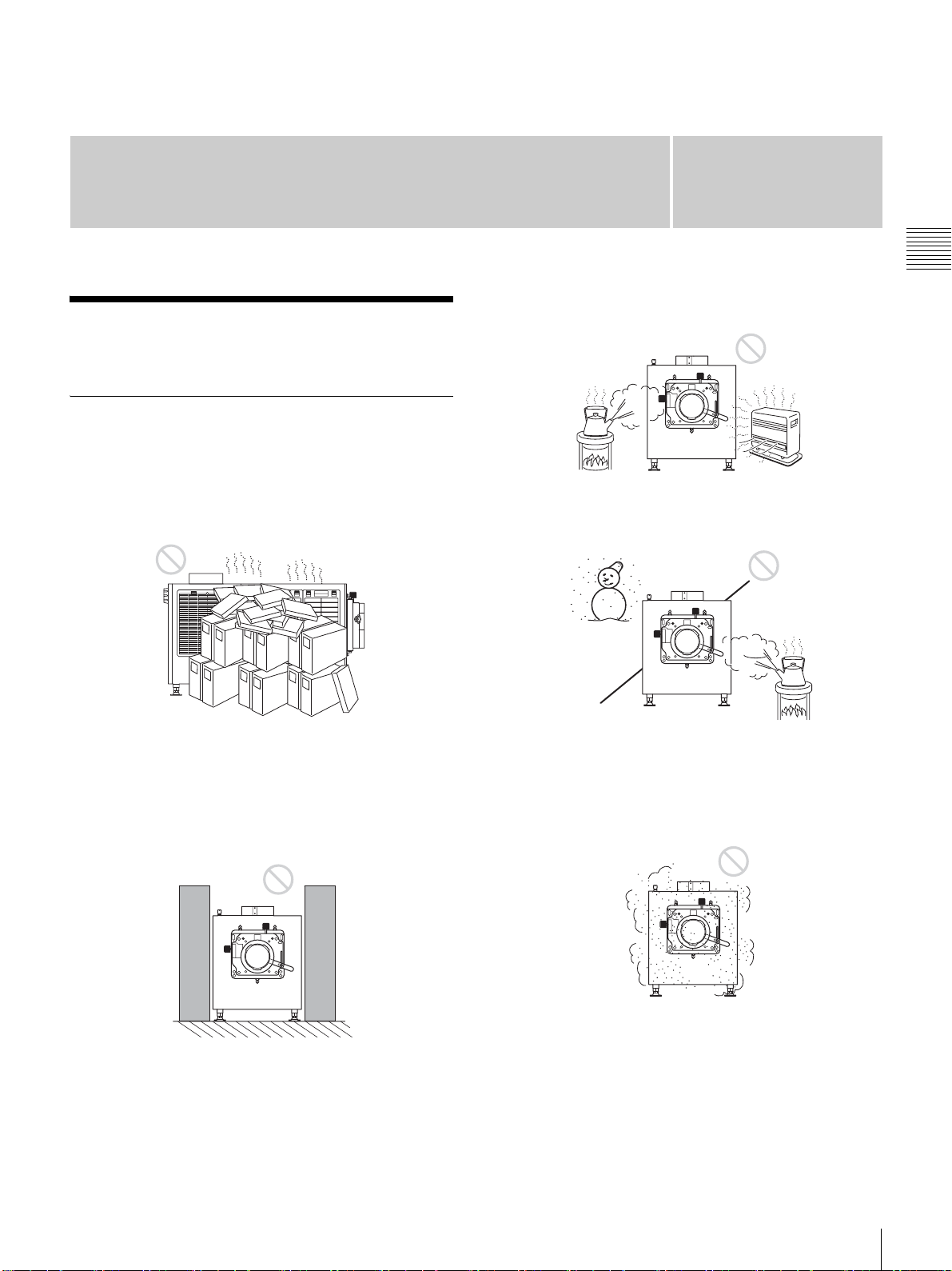
設置に適さない場所
次のような場所には設置しないでください。本機の故障や
破損の原因となります。
温度や湿度が高い場所
第章
2
第 2 章 準備
風通しが悪い場所
吸気口、排気口は、内部の温度上昇を防ぐためのものです。
風通しの悪い場所を避け、吸気口および排気口をふさがな
いように設置してください。
排気口をふさぐ場所
急激な温度変化のある場所
本機を設置している室内の急激な温度変化は結露を引き起
こし、故障の原因となりますので冷暖房にご注意ください。
ほこりが多い場所
本機側面や上面の排気口のそばに物を置くと、排気が吸気
口に回りこみ、内部の温度が上昇して保護回路が動作する
ことがあります。排気をさえぎらないように注意して本機
を設置してください。本機の周囲から 1m 以内には物を置
かないようにしてください。
設置・使用時のご注意
11
Page 12
使用に適さない状態
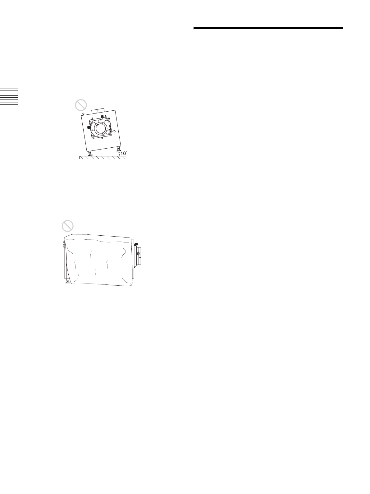
次のような状態では使用しないでください。
本機を横倒しや逆さまにして使用する
本機を左右に傾ける
第 2 章 準備
本機を± 10°以上傾けてお使いになることは避けてくださ
い。色むらやランプの寿命を著しく損ねる原因となること
があります。
吸気口および排気口を覆う
吸気口および排気口をふさぐような覆いやカバーをしたり、
毛足の長いじゅうたんなどの上では使用しないでください。
吸気口および排気口がふさがれると、内部の温度が上昇し
ます。
◆ 吸気口および排気口の位置については、「各部の名称と働き」(7
ページ)をご覧ください。
SRXController をコン
トロール用 PC にインス
トールする
SRXController をコントロール用 PC にインストールする
と、PC から本機を操作できます。
コンピューターに SRXController がインストールされてい
る場合は、事前にアンインストールを行ってください。
動作環境
SRXController を動作させるには、次の条件を備えたコン
ピューターを用意してください。
オペレーティングシステム(OS):
WindowsVistaBusinessSP2(日本語または英語版)
(× 64Edition を除く)
Windows7EnterpriseSP1(日本語または英語版)
CPU:IntelPentiumM1.6GHz 以上、かつ OS が推奨する
CPU
メモリー:256MB 以上、推奨 512MB 以上、かつ OS が推
奨するメモリー
HDD 空き容量:15MB 以上(コンピューターの内蔵ドラ
イブ)
モニター:XGA(1024 × 768)以上
通信:LAN(10BASE-T/100BASE-TX)、または COM
(RS-232C)
WindowsVista/7 のユーザーアカウント
制御について
WindowsVista/7 ではファイルのセキュリティを高めるた
め、ユーザーアカウント制御(UAC)を搭載しています。
SRXController もこのユーザーアカウント制御に対応して
おり、インストール中や操作中にユーザーアカウント制御
の警告画面が表示されることがあります。
警告画面が表示されたら下記の手順を行ってください。
12
下記の画面が表示された場合
[ 許可 ] を選択すると作業を続行できます。
SRXController をコントロール用 PC にインストールする
Page 13

2
[Next] をクリックする。
ソフトウェア使用許諾条件が表示されます。
3
内容をよく読み、[Iacceptthetermsinthelicense
agreement]を選択して、[Next]をクリックする。
第 2 章 準備
ご注意
[ キャンセル ] を選択するとアプリケーションを実行するこ
とはできません。
管理者パスワードの入力画面が表示された場合
管理者パスワードを入力し、[OK] をクリックします。
[Idonotacceptthetermsinthelicenseagreement]を
選択した場合は、ソフトウェアのインストールは行わ
れずに、ウィザードが終了します。
4
インストール先のフォルダーを選択し、[Next]をク
リックする。
インストール先を変更する場合は、[Change]をク
リックし、インストールするフォルダーを指定します。
SRXController をインストールする
1
インストーラーによってダウンロードされたインス
トールウィザードを起動する。
SRXController をコントロール用 PC にインストールする
13
Page 14
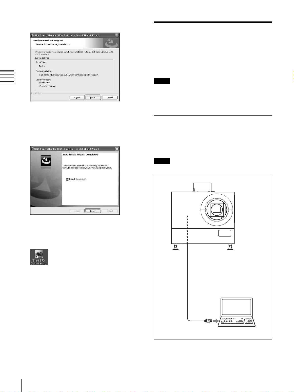
5
[Install]をクリックする。
コントロール用 PC を接
続する
内部接続されているイーサネットケーブル、または
RS-232C 端子のどちらかに PC を接続します。
第 2 章 準備
インストールが開始されます。
6
次の画面が表示されたら、[Finish]をクリックする。
[Launchtheprogram]にチェックマークを付けると、
すぐに SRXController を起動できます。
以上で SRXController のインストールは完了です。
SRXController をインストールすると、デスクトップ
に「StartSRXControllerforSRX-Tseries」アイコン
が作成されます。
ご注意
NETWORK 端子(LAN)と RS-232C 端子(COM)の両方
を一緒に接続すると、通信エラーを起こす可能性がありま
す。どちらか一方での接続にしてください。
イーサネットケーブルで接続する
内部接続されているイーサネットケーブル(付属)を PC
のイーサネット端子に接続します。
イーサネットケーブルの本体への接続は、お買い上げ店ま
たはソニーのサービス窓口にご依頼ください。
ご注意
PC の IP アドレス取得方法を DHCP に設定してください。
14
イーサネットケーブル
(クロスケーブル)(付属)
コントロール用 PC
イーサネット端子へ
コントロール用 PC を接続する
Page 15
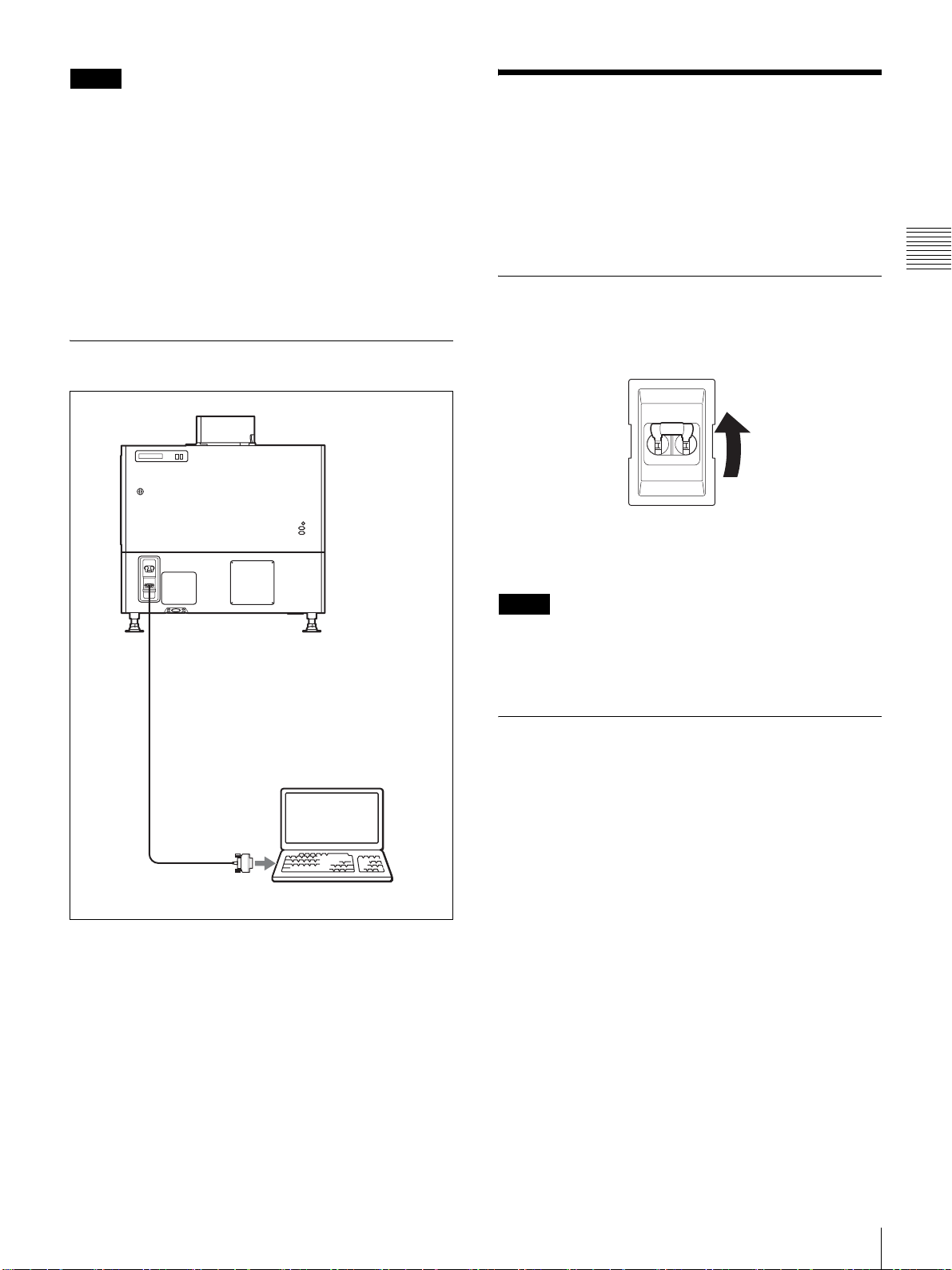
ご注意
• 安全のために、周辺機器を接続する際は、過大電圧を持
つ可能性があるコネクターをこの端子に接続しないでく
ださい。
接続については本書の指示に従ってください。
• イーサネットケーブルを本体に接続せずに本体の電源を
長時間入れたままにしていた場合、イーサネットケーブ
ルを接続し、ネットワーク接続の再設定を行っていると、
STATUSMESSAGE 表示窓に「SonyDataProjector
Initializing...」と表示される場合がありますが、異常では
ありません。
RS-232C 端子に接続する
SRXController を起動
する
プロジェクターの主電源を入れてから、SRXController を
起動して、プロジェクターを起動します。
第 2 章 準備
プロジェクターの主電源を入れる
プロジェクター後面の電源スイッチをオン側(|)に倒し
て、電源を入れます。
主電源が入り、プロジェクターがスタンバイ状態になると、
MAIN インジケーターと LAMP インジケーターが赤色に
点灯します。
RS-232C 端子へ
接続ケーブル(別売)
RS-232C 端子へ
コントロール用 PC
ご注意
プロジェクターのイニシャライズが完了し、ステータス
メッセージ表示部のメッセージが消えてから SRX
Controller を接続してください。
SRXController を起動する
起動する前に
コントロール用 PCに市販のファイアウォールソフトウェ
アをインストールしている場合、Windows のファイア
ウォールを有効にしている場合は、ファイアウォールの設
定を解除する必要があります。
Windows7 の場合
[Windows ファイアウォール]を起動し、[Windows ファ
イアウォールを介したプログラムまたは機能を許可する]
をクリックして、許可されたプログラム内の SRX
Controller にチェックマークを付けるか、リストにない場
合は[設定の変更]を選択した後、[別のプログラムの許
可]から SRXController を追加してください。
市販のファイアウォールソフトウェアをインストールして
いる場合
ファイアウォールソフトウェアの取扱説明書を参照し、許
可リストに「SRXController」を追加してください。
SRXController を起動する
15
Page 16

SRXController を起動するには
1 2
PC 画面上の アイコンをダブルクリックします。
SRXController が起動し、プログラム・ランチャー画面が
表示されます。
接続モードを変更する
本機とコントロール用 PC がネットワーク接続されている
場合は、IP アドレスを直接指定して接続できます。また、
RS-232C を介して接続することもできます。
プログラム・ランチャー画面について
12
第 2 章 準備
a メニューバー
File(ファイル)
SRXController を終了するとき、[File] メニューから [Quit]
を選びます。
Connect(接続)
本機とコントロール用 PC との接続モードを選びます。
◆ 詳しくは、「接続モードを変更する」(16 ページ)をご覧くださ
い。
Help(ヘルプ)
[Help] メニューから [Version] を選ぶと、この SRX
Controller のバージョン情報を表示します。
イーサネットで IP アドレスを指定して接続する場合
メニューバーの [Connect] メニューから [Network] を選び、
表示されるダイアログにプロジェクターの IP アドレスと機
種名を入力し、[OK] ボタンをクリックします。
ポート番号を変更する場合は、メニューバーの [Connect]
メニューから [PCPortSetting] を選び、表示されるダイア
ログにポート番号を入力し、[OK] ボタンをクリックしま
す。
RS-232C で接続する場合
メニューバーの [Connect] メニューから [COM] を選び、表
示されるダイアログに、プロジェクターと通信する PC の
COM ポート(RS-232C)のポート番号と機種名を入力し、
[OK] ボタンをクリックします。
b プロジェクター検出画面
ネットワークに接続されているプロジェクターの情報が表
示されます。
Alert:プロジェクターのエラー情報の有無( :有、 :
無)
ModelName:プロジェクターの機種名
SerialNo.:プロジェクターのシリアル番号
Type:IPv6/IPv4 接続可能なプロトコルのタイプ
IPAddress:プロジェクターの IP アドレス
Connection:ネットワークとの接続状態
この SRXController で選択できるプロジェクターは、
[Connection(接続)] 欄に [Connectable(接続可能)]
と表示されます。
Power:プロジェクターの電源の状態
Region:プロジェクターを設置している地域
Location:プロジェクターの設置場所
Name:任意の名前
SRXController を終了するには
メニューバーの [File] メニューから [Quit] を選びます。
16
SRXController を起動する
Page 17
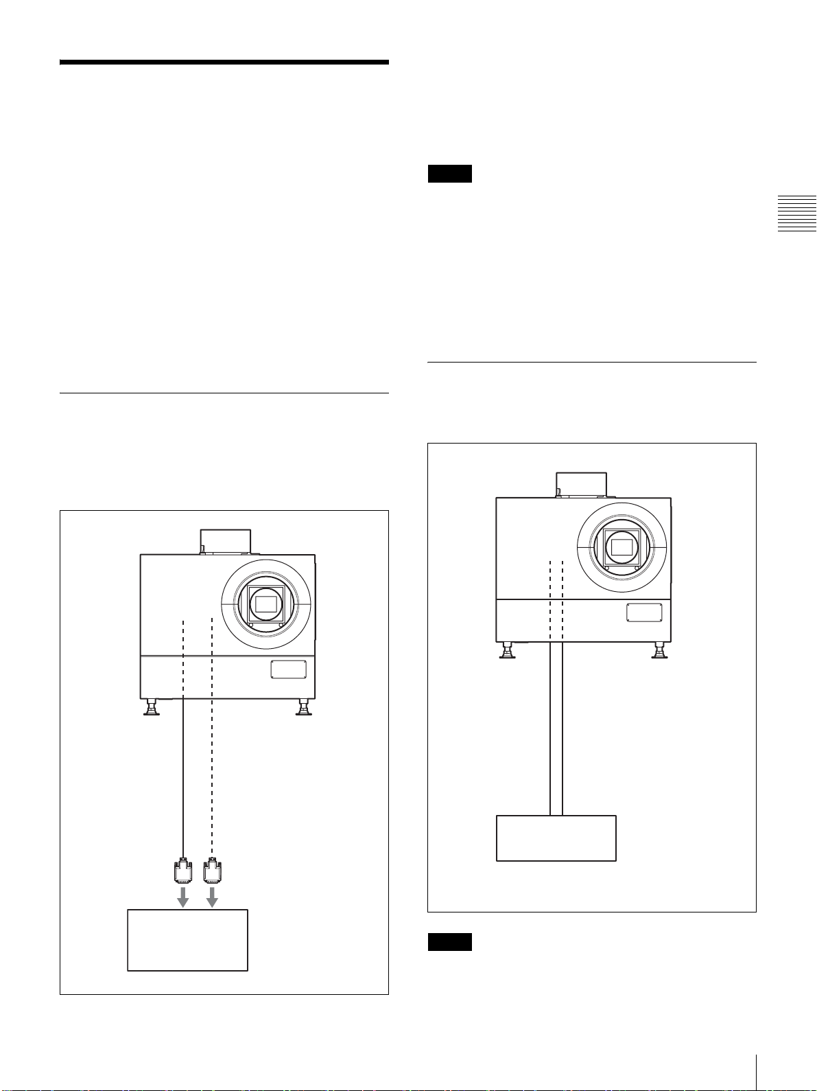
投影する機器を接続する
接続するときは
• 各機器の電源を切った状態で接続してください。
• 接続ケーブルは、それぞれの端子に合った正しいものを
選んでください。
• プラグはしっかり差し込んでください。不完全な接続は
画像の乱れの原因になります。抜くときは、必ずプラグ
を持って抜いてください。
• 接続する機器の取扱説明書もあわせてご覧ください。
• 本機にインプットボードを取り付けるときは、お買い上
げ店またはソニーのサービス窓口にご依頼ください。
• 本体内部への接続ケーブルの接続は、お買い上げ店また
はソニーのサービス窓口にご依頼ください。
LKRI-005 から信号を入力する場合、一部の解像度の信号で
は、HDCP(High-bandwidthDigitalContentProtection)
の DVI-D 信号も入力できます。
◆ 詳しくは、LKRI-005 の取扱説明書をご覧ください。
ご注意
• DVI-D 端子に接続する場合、入力する信号に応じて、
「PICTURECONTROL」画面の [InputSource] の [Signal
Mode] で入力信号を設定してください。(23 ページ)
• 長尺ケーブルを使用した場合、信号の減衰により正しく
表示できないことがあります。
• 10 ビット信号を入力するときに DVI-D 端子のみで接続す
る場合(10 ビットシングルモード)は、Dual-link 対応の
DVI ケーブルをご使用ください。
HD-SDI 機器を接続する
第 2 章 準備
PC を接続する(DVI-D 接続)
本体内部のインプットボード取り付け部の INPUTA から
INPUTD のいずれかに HDCPDVI ボード LKRI-005 を装
着し、LKRI-005 に接続した DVI ケーブルを PC に接続し
ます。
DVI ケーブル
(別売)
本体内部のインプットボード取り付け部に別売のインプッ
トボード LKRI-003 を装着し、HD-SDI 機器と接続します。
HD-SDI 接続ケーブル
(別売)
HD-SDI 出力端子へ
DVI-D 端子へ
PC
AUX 端子へ
HD-SDI 機器など
ご注意
LKRI-003 装着時は、「PICTURECONTROL」画面の
[InputSource] の [SignalMode] で入力信号の種類を選択し
てください。Single-link で入力する場合は、[YPbPr] または
投影する機器を接続する
17
Page 18

[YPbPrFULL] に設定してください。Dual-link で入力する
場合は、[RGB] または [RGBFULL] に設定してください。
◆ 詳しくは、23 ページをご覧ください。
HDMI 機器を接続する
本体内部のインプットボード取り付け部に別売のインプッ
トボード LKRI-006 を装着すると、HDMI 機器と接続でき
第 2 章 準備
ます。詳しくは、お買い上げ店またはソニーのサービス窓
口にお問い合わせください。
18
投影する機器を接続する
Page 19
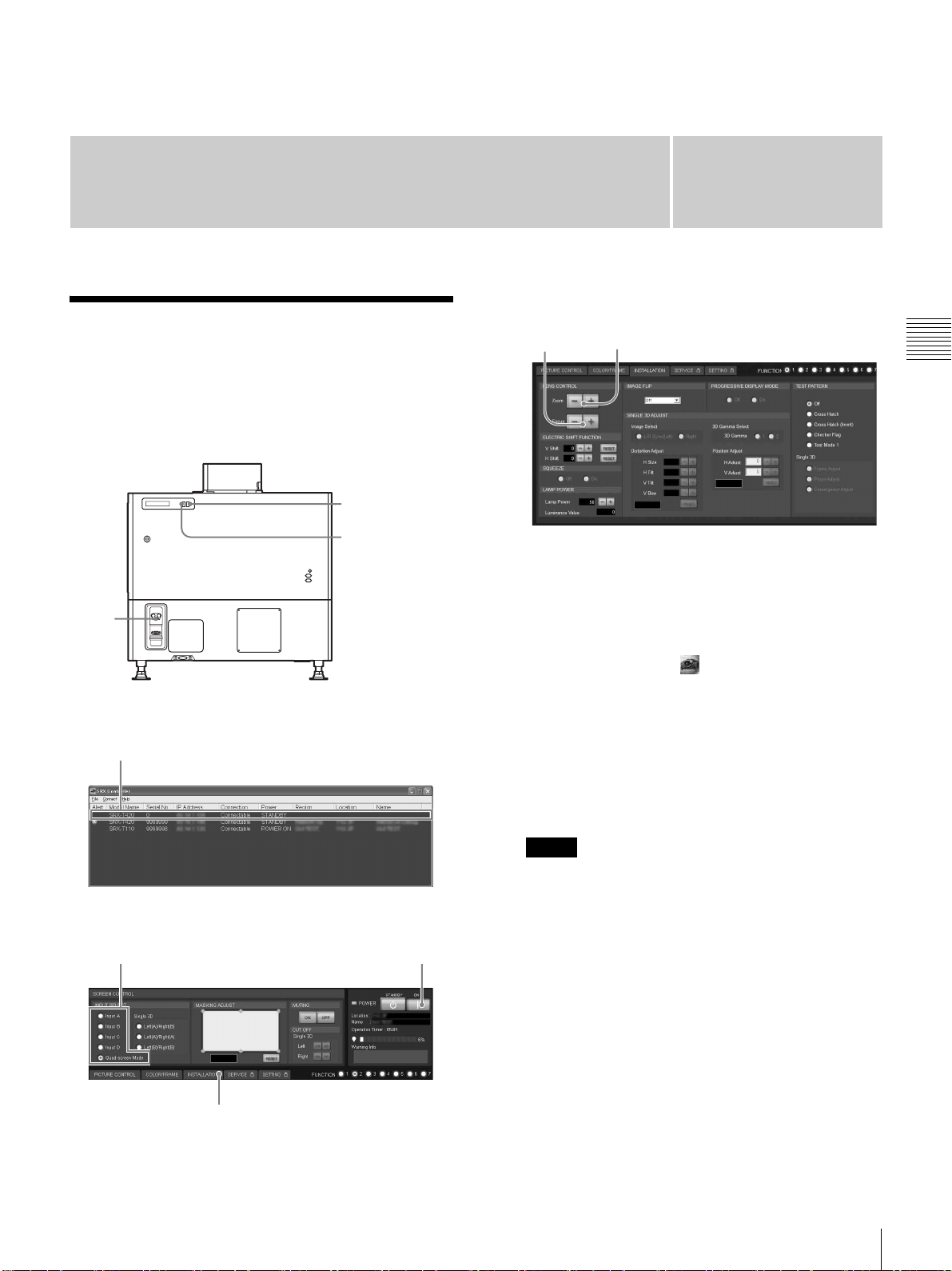
3
投影
スクリーンに画像を映す
SRXController をインストールした PC の画面上で操作し
ます。
LAMP
インジケーター
MAIN
インジケーター
第章
「INSTALLATION」画面
8,10 9
1
本体後面の電源スイッチをオン側(?)にする。
第 3 章 投影
1
プログラム・ランチャー画面
3
「ControlFunctionMenu」画面
6
4
本体後面の MAIN インジケーターと LAMP インジ
ケーターが赤色に点灯し、スタンバイ状態になります。
2
PC を起動し、画面上の アイコンをダブルクリック
する。
プログラム・ランチャー画面が表示されます。
3
操作したいプロジェクターをダブルクリックする。
SRXController が起動し、「ControlFunctionMenu」
画面が表示されます。
ご注意
ネットワーク接続の場合、直接 IP アドレスを指定し
て、操作するプロジェクターを選ぶこともできます。
また、RS-232C 端子経由で接続している場合は、RS232C のポート番号を指定してください。
◆詳しくは、「接続モードを変更する」(16 ページ)をご覧く
ださい。
4
[POWERON?] ボタンをクリックして電源を入れる。
MAIN インジケーターと LAMP インジケーターが緑色
に点灯します。
7
5
映像を映す機器の電源を入れる。
スクリーンに画像を映す
19
Page 20
6
スクリーンに映す映像を選ぶ。
電源を切るには
SCREENCONTROL 画面の INPUTSELECT ラジオボ
タンをクリックして入力信号を選びます。
InputA:INPUTA に装着されたインプットボード
(標準装備)の端子に接続した機器からの映像を映
すとき
InputB 〜 InputD:INPUTB 〜 INPUTD に装着され
たインプットボード(別売)の端子に接続した機
器からの映像を映すとき
Quad-screenMode:4 画面モードで映すとき
INPUTA(左上)、INPUTB(右上)、INPUTC
(左下)、INPUTD(右下)の 4 画面が同時に 1 つ
第 3 章 投影
7
8
9
10
のスクリーンに表示されます。
ご注意
「PICTURECONTROL」画面で、[InputSource] の
[SignalMode] が正しく設定されていないと映像が乱れ
る場合があります。
◆ 詳しくは、23 ページをご覧ください。
手順 6 で [Quad-screenMode](4 画面モード)を
選んだ場合のご注意
• 動画を 4 画面モードで投影する場合は、投影する信号
すべてにゲンロックをかけ、各信号の位相差が 5
μsec 以内になるように同期を合わせてください。同
期が取れていない象限の動画は、こま落ちして見え
ることがあります。4 画面モードでは左上の画像が基
準画像となります。動画と静止画を併せて投影する
場合は、動画を左上の画面に投影するように選択し
てください。
• UXGA、WUXGA など垂直方向の解像度が 1080 を超
える信号を投影すると、画像が一部欠けて表示され
ます。
[INSTALLATION] ボタンをクリックする。
「INSTALLATION」画面が表示されます。
[LENSCONTROL]の [Focus+/–] ボタンでフォーカス
を調整する。
[Zoom+/–] ボタンで画像の大きさを調整する。
[Focus+/–] ボタンで再度フォーカスを調整する。
1
[POWERSTANDBY1] ボタンをクリックし、表示さ
れる確認画面で [OK] ボタンをクリックする。
MAIN インジケーターと LAMP インジケーターが緑色
に点滅します。本機がランプ温度を検出し、ランプ温
度を下げるため 3 〜 15 分間ファンが回り続けます。
ファンが止まると MAIN インジケーターと LAMP イ
ンジケーターが赤く点灯します。
2
本体後面の電源スイッチをオフ側(a)にする。
ご注意
ファンが回っている間は、本体の電源スイッチで電源
を切らないでください。電源スイッチを強制的に切る
とファンが止まり、ランプ温度が充分下がらず、故障
の原因となることがあります。
4K 信号を 4 画面モードで映す
4K 信号を 4 枚のインプットボードから分割して入力し、
4K 映像として 4 画面モードで映すことができます。
4K 映像を映すときは、4 つの入力信号すべてにゲンロック
をかけ、各信号の位相差が 5μsec 以内になるように同期
を合わせてください。また、「PICTURECONTROL」画面
の [InputSource] の [SignalMode] と [I/PMode] を、
INPUTA から INPUTD まで同じ設定にしてください。
上記の設定を行ったら、「INSTALLATION」画面の
[PROGRESSIVEDISPLAYMODE] の [On] ラジオボタンを
クリックします。
ご注意
• [PROGRESSIVEDISPLAYMODE] が有効になるのは、
次の信号が同じリフレッシュレートで入力されている場
合です。
−4 つの 1920 × 1080 信号
−4 つの 2048 × 1080 信号
−4 つの SXGA+(1400 × 1050)信号
上記以外の信号のときは、[PROGRESSIVEDISPLAY
MODE] を選択できません。
• 信号の種類によっては、表示に一部、制限があります。
4K 映像に対応している信号かどうかについて詳しくは、
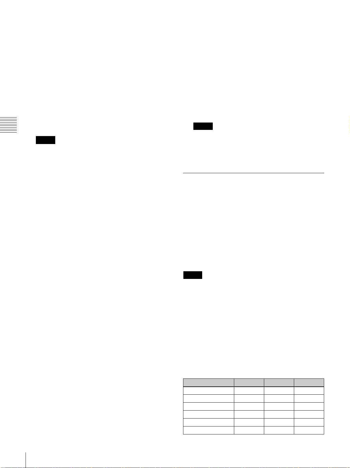
下記の表をご覧ください。
画面全体の映像を消すには
[MUTING] の [ON] ボタンをクリックすると、映像が消え、
スクリーン全体が黒画面になります。[MUTING] の [OFF]
ボタンをクリックすると映像が表示されます。
スクリーンに画像を映す
20
信号 LKRI-003 LKRI-005 LKRI-006
108060i ▲ − ▲
1024 × 768VESA60 − ● ●
1024 × 768VESA70 − − −
1024 × 768VESA75 − − −
1024 × 768VESA85 − − −
1280 × 960VESA60 − ● ●
Page 21
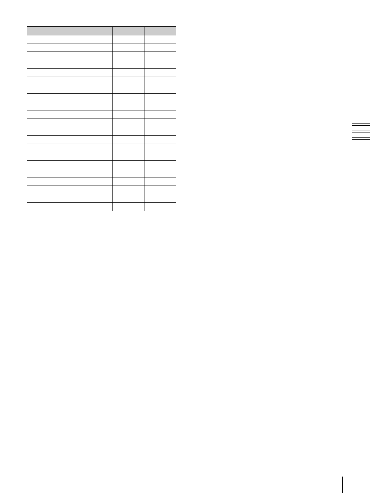
信号 LKRI-003 LKRI-005 LKRI-006
1280 × 1024VESA60 − ● ●
1280 × 1024VESA75 − − −
1280 × 1024VESA85 − − −
1600 × 1200VESA60 − × ×
108050i ▲ − ▲
72060P ● ● ●
72050P ● ● ●
108024PsF ○ − −
1400 × 1050VESA60 − ○ ○
2048 × 108048i ▲ − −
2048 × 108050i ▲ − −
2048 × 108060i ▲ − −
108024P ○ ○ ○
108050P ○
108060P ○
2048 × 108024P ○ ○ ○
2048 × 108025P ○ − −
2048 × 108030P ○ − −
2048 × 108048P ○
2048 × 108060P ○
1920 × 1200DVI60 − × ×
1)
1)
1)
1)
○○
○○
○−
○○
第 3 章 投影
○:静止画でも動画でも 4K 映像を投影できる
●:静止画の場合でも動画の場合でも、中央に線が表示される
▲:動画の場合のみ、中央に横線が表示される
×:画像の下部が切れるため、4K 映像にならない
−:静止画でも動画でも 4K 映像を投影できない
1) 送りの信号に 4:4:4 ⇒ 4:2:2 変換のフィルターがかかっている場
合は、画面中央に縦筋が発生する場合があります。フィルター
をかけない信号を用意してください。
スクリーンに画像を映す
21
Page 22
SRXController で行う調整
と設定
コントロール画面を消すには
第章
4
コントロール画面を表示
する
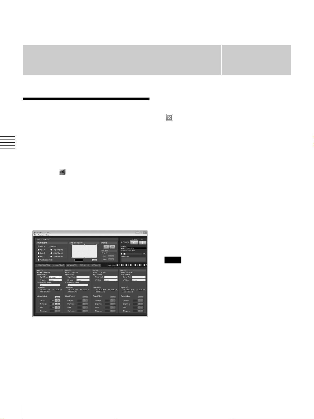
本機では、SRXController をコントロール用 PC にインス
第 4 章 SRXController で行う調整と設定
トールすると、画質の調整や入力信号の設定、設置設定の
変更などを PC の画面で操作することができます。
1
PC 画面上の アイコンをダブルクリックする。
プログラム・ランチャー画面が表示されます。
2
操作したいプロジェクターを選び、ダブルクリックす
る。
SRXController が起動し、「ControlFunctionMenu」
画面が表示されます。
メニューバーの [File] メニューから [Quit] を選ぶか、
(終了)ボタンをクリックします。
設定値をリセットするには
「PICTURECONTROL」画面の [RESET] ボタンをクリッ
クすると、[SignalAdjust] の調整可能な項目の設定が工場
出荷時の値に戻ります。「COLOR/FRAME」画面の
[RESET] ボタンをクリックすると、[FrameAdjust] の項目
の設定すべてが工場出荷時の値に戻ります。
設定値の記憶について
本機では、FUNCTION1 〜 FUNCTION7 までの 7 種類の
設定を登録できます。
初期設定では、設定値は FUNCTION1 に自動的に記憶され
ます。他のメモリーに登録する場合は、「ControlFunction
Menu」画面の FUNCTION ボタンの [2] から [7] のいずれか
のラジオボタンをクリックし、各画面で調整、設定を行い
ます。
また、登録した設定値を呼び出すには、希望の
FUNCTION ボタンをクリックします。
ご注意
別の FUNCTION 設定に切り換えるとき、FUNCTION ボ
タンをクリックすると、映像がいったんミューティング状
態になります(最大 10 秒間程度)。その後、選択した設定
の画面に切り換わります。
22
3
[PICTURECONTROL]、[COLOR/FRAME]、
[INSTALLATION] ボタンのいずれかをクリックし、
操作したい画面を表示させる。
◆ 詳しくは、「PICTURECONTROL(ピクチャーコントロー
ル)画面」(23 ページ)、「COLOR/FRAME(カラー/フ
レーム)画面」(24 ページ)、「INSTALLATION(設置設
定)画面」(26 ページ)をご覧ください。
コントロール画面を表示する
調整できない項目について
入力信号によって調整できない項目は、画面に表示されま
せん。
◆詳しくは、「入力信号と調整・設定項目」(27 ページ)をご覧く
ださい。
Page 23
PICTURECONTROL
(ピクチャーコントロー
ル)画面
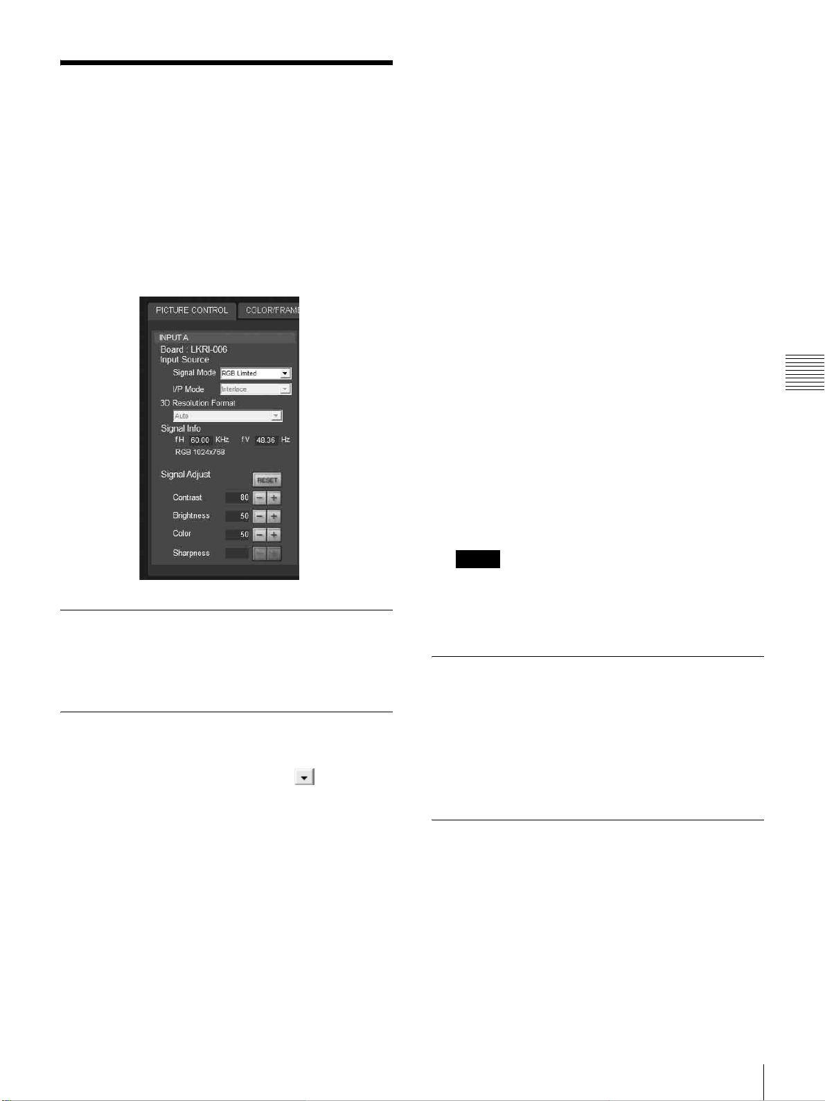
入力信号の選択や、画質の調整を行います。
INPUTSELECT ラジオボタンで [Quad-screenMode](4 画
面モード)を選択した場合は、画面に表示されている入力
チャンネルごとに調整できます。
LKRI-003 装着時
Single-link で入力する場合、[YPbPr] または [YPbPr
FULL] を選びます。
Dual-link で入力する場合、[RGB] または [RGBFULL]
を選びます。
[RGB] または [YPbPr] を選ぶと、「PICTURE
CONTROL」画面の [SignalAdjust] で Contrast を 90
に設定して 10 ビットの HD-SDI 信号を入力した場合、
HD-SDI 信号の 64 〜 960 のデータ値
ターの 0 〜 100% の映像レベルになるようにマッピン
グ処理して、プロジェクターに表示します。
[RGBFULL] または [YPbPrFULL] を選ぶと、同じく
Contrast を 90 に設定して 10 ビットの HD-SDI 信号を
入力した場合、HD-SDI 信号の 0 〜 1023 のデータ値を
プロジェクターの 0 〜 100% の映像レベルになるよう
にマッピング処理して表示します。このとき、HD-SDI
信号に含まれる禁止コード(0 〜 3、1020 〜 1023 の
データ領域)はマスクされます。
1)
HD-SDI 信号 10 ビット入力では、映像レベル 0%(黒)の
データ値は 64、100%(白)のデータ値は 960 になります。
LKRI-006 装着時
入力信号に合わせて選びます。
1)
をプロジェク
第 4 章 SRXController で行う調整と設定
Board(インプットボード)
本機の該当するスロットに装着されているインプットボー
ドを表示します。
InputSource(入力ソース)
SignalMode(信号モード):別売のインプットボードに接
続した機器からの入力信号の種類を、 をクリックし
て表示されるドロップダウンリストから選びます。
LKRI-005 装着時
入力する DVI-D 信号の種類を選びます。
通常は、[8bitSingleFull](DVI1.0 準拠、FullRange
対応)を選びます。
DTV 規格の信号を入力するときは、[8bitSingle
Limited](DVI1.0 準拠、LimitedRange 対応)を選び
ます。
独自仕様の 10 ビット信号を入力するときは、Full
Range 対応の [10bitTwinFull] または [10bitSingle
Full]、LimitedRange 対応の [10bitTwinLimited] また
は [10bitSingleLimited] のいずれかを選びます。
I/PMode(I/P モード):I/P 変換モードを選択します。信
号ソースに応じて、[Interlace](インターレース)また
は [PsF]、[108050p60p] に設定します。
ご注意
• この項目は、インターレース信号および PsF 信号、
HD の 50P、60P 信号入力時に有効です。
• LKRI-005 装着時は [I/PMode] の選択はできません。
3DResolutionFormat(3D 解像
度フォーマット)
INPUTSELECT ラジオボタンで[Single3D]を選んだ場
合、通常は[Auto]を選びます。
投影される画が正常でない場合は、入力データに合わせて
選んでください。
SignalInfo(信号情報)
入力信号の水平/垂直周波数を自動的に表示します。数値
は目安です。
また、周波数表示の下に入力信号の種類が表示されます。
fH:水平周波数を表示します。
fV:垂直周波数を表示します。
PICTURECONTROL(ピクチャーコントロール)画面
23
Page 24
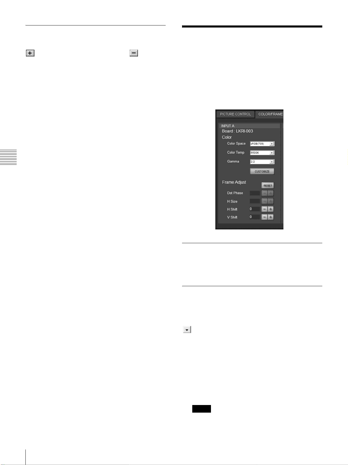
SignalAdjust(信号調整)
入力信号の画質を調整します。
をクリックすると設定値が大きくなり、 をクリック
すると設定値が小さくなります。
[RESET] ボタンで、以下の 4 項目を工場出荷時の値にリ
セットできます。
Contrast(コントラスト):コントラストを調整します。設
定値が大きくなるほどコントラストが強くなります。
Brightness(ブライトネス):明るさを調整します。設定値
が大きくなるほど明るくなります。
Color(カラー):色の濃さを調整します。設定値が大きく
なるほど色が濃くなります。
Sharpness(シャープネス):シャープネスを調整します。
設定値が大きくなるとくっきりします。設定値が小さ
くなると柔らかくなります。
第 4 章 SRXController で行う調整と設定
COLOR/FRAME(カ
ラー/フレーム)画面
入力信号の設定を変更します。
INPUTSELECT ラジオボタンで [Quad-screenMode](4 画
面モード)を選択した場合は、画面に表示されている入力
チャンネルごとに調整できます。
Board(インプットボード)
本機の該当するスロットに装着されているインプットボー
ドを表示します。
Color(カラー)
正しい色再現が得られるように設定します。
画像の色がおかしい場合は、まず [ColorSpace] の設定を確
認してください。
をクリックして表示されるドロップダウンリストから
選びます。
ColorSpace(カラースペース):色調再現範囲を選択しま
す。
sRGB(709):通常のハイビジョン信号や RGB 信号を映
す場合
DCDM:DCI スペックブック /Version1.0 で規定され
た MinimumD-CinemaColorGamut で映す場合
CIEXYZ:XYZ 信号を LKRI-003 から入力する場合
ご注意
「PICTURECONTROL」画面の [InputSource] の
[SignalMode] を [RGBFULL] に設定してください。
24
COLOR/FRAME(カラー/フレーム)画面
Page 25
AdobeRGB:AdobeRGB に対応した PC 信号を映す
場合
CUSTOM:ユーザーによって設定されたカラースペー
スで映す場合。工場出荷時は DCDM と同じ値が設定さ
れています。
ColorTemp(色温度):色温度を選択します。[DCIW/P]、
[6500K]、[9300K]、[CUSTOM1]、[CUSTOM2]、
[CUSTOM3] から選択します。CUSTOM1 〜
CUSTOM3 には 6500K が初期設定されています。
通常のハイビジョン信号や RGB 信号を映す場合は、
[6500K] を選択することをおすすめします。映画素材を
映す場合は [DCIW/P] に設定してください。
Gamma(ガンマ):ガンマ補正モードを選択します。数値
が小さいほど明るくなります。映像ソースに応じて選
択してください。通常のハイビジョン信号や RGB 信号
の素材を映す場合は、[2.2] を選択することをおすすめ
します。
ガンマの値は入力信号に合わせて、[2.6] または [2.2] を
選択するか、1.80 から 2.59 まで(2.20 を除く)の値を
0.01 刻みで設定します。これにより、最適な輝度で映
像を投影できます。
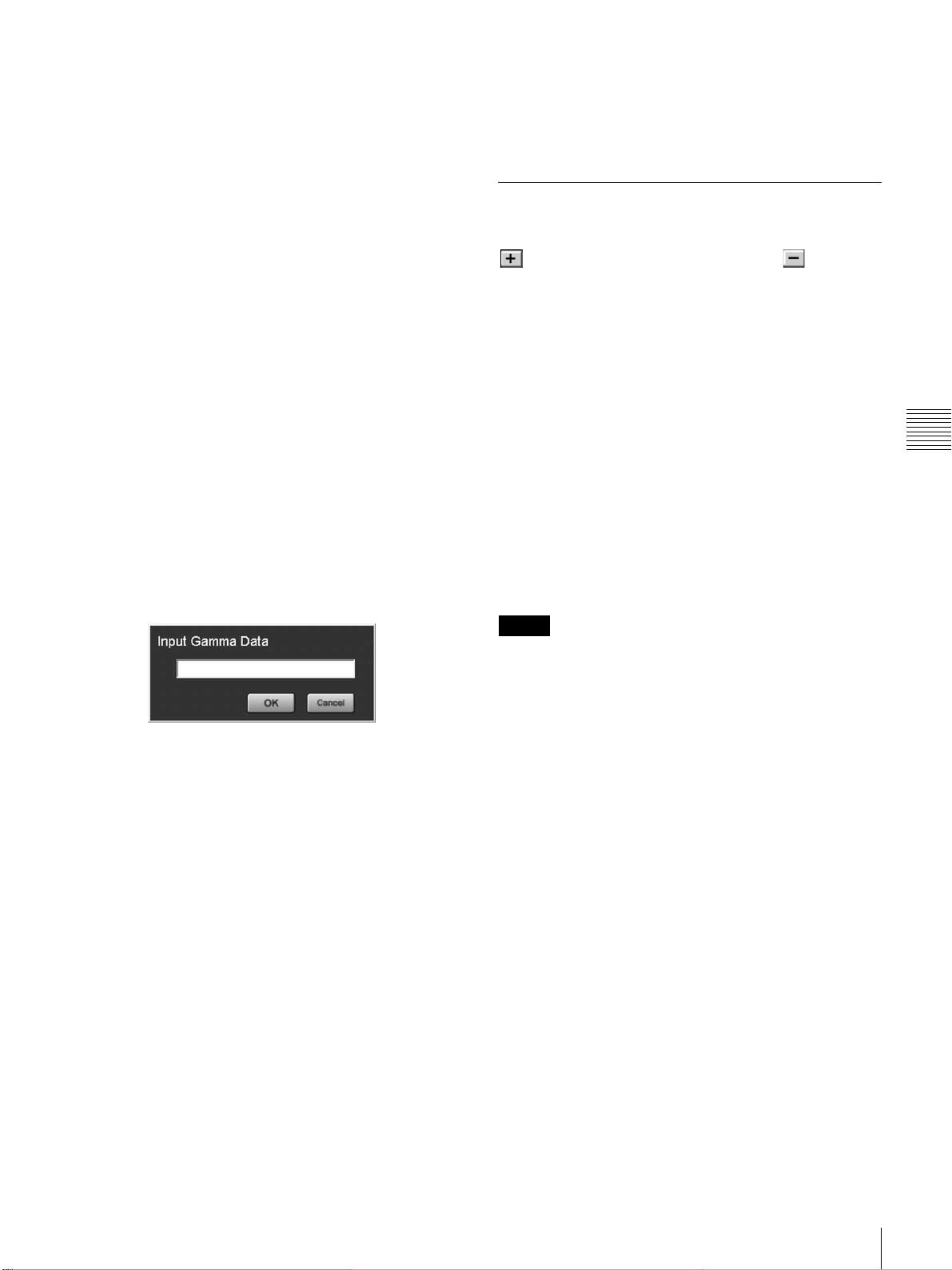
0.01 刻みでガンマの値を設定するには、[Gamma] を
[1.8] に設定し、[CUSTOMIZE] ボタンをクリックしま
す。ガンマデータの入力画面が表示されたら数値を入
力し、[OK] ボタンをクリックします。
Gamma の設定
2.6:2.6
2.2:2.2
CUSTOMIZE:CUSTOMIZE で設定した値
FrameAdjust(フレーム調整)
画像の位置やサイズを調整します。
をクリックすると設定値が大きくなり、 をクリック
すると設定値が小さくなります。
[RESET] ボタンで、フレーム調整すべての項目を工場出荷
時の値にリセットできます。
DotPhase(ドットフェーズ):SXRD パネルと入力される
信号の位相を調整します。画像がいちばんくっきり見
える位置に合わせます。本機では使用できません。
HSize(水平サイズ):入力信号に合わせて画面の大きさを
調整します。設定値が大きくなるほど画面の左右幅が
広がります。本機では使用できません。
HShift(水平位置):画面の左右の位置を調整します。設
定値が大きくなると画面が右に、設定値が小さくなる
と画面が左に移動します。
VShift(垂直位置):画面の上下の位置を調整します。設定
値が大きくなると画面が上に、設定値が小さくなると
画面が下に移動します。
第 4 章 SRXController で行う調整と設定
LKRI-005 に信号を入力したときは
[Color] の各項目を設定すると、EDIDROM の色域記述エリ
アに設定が書き込まれます。
各項目を選択したときに EDIDROM に書き込まれる値は、
以下のとおりです。
ColorSpace の設定
sRGB(709):Red(0.6400,0.3300)、Green(0.3000,
0.6000)、Blue(0.1500,0.0600)
AdobeRGB:Red(0.6400,0.3300)、Green(0.2100,
0.7100)、Blue(0.1500,0.0600)
DCDM、CIEXYZ、CUSTOM:Red(0.6800,0.3200)、
Green(0.2650,0.6900)、Blue(0.1500,0.0600)
ColorTemp の設定
6500K:White(0.3127,0.3290)
9300K:White(0.2840,0.2970)
DCIW/P:White(0.3140,0.3510)
CUSTOM1 〜 CUSTOM3:White(0.3127,0.3290)(デ
フォルト値)
ご注意
フレーム調整で画像を正しい位置に調整していないと画像
の外にノイズが現れる場合がありますが、故障ではありま
せん。[FrameAdjust] で正しい位置に調整してください。
COLOR/FRAME(カラー/フレーム)画面
25
Page 26
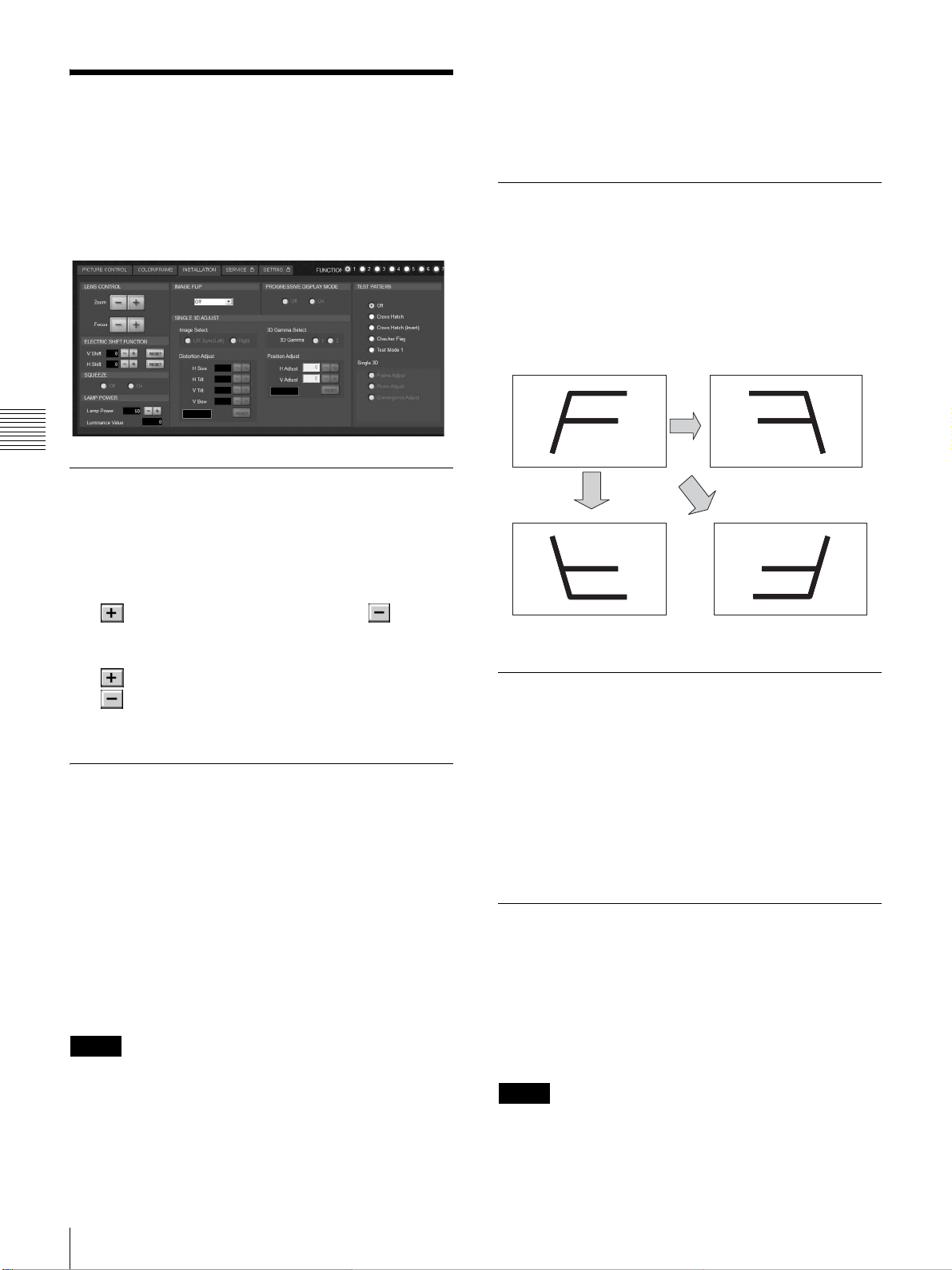
INSTALLATION(設置
設定)画面
• この機能を 4 画面モードでご使用になる場合は、投影する
信号すべてにゲンロックをかけ、各信号の位相差が 5
μsec 以内になるように同期を合わせてください。同期
が取れていないと画像が正しく表示されません。
画面の調整やプロジェクターの設置状態の選択、ランプ出
力の調整などを行います。
第 4 章 SRXController で行う調整と設定
LENSCONTROL(レンズコント
ロール)
スクリーンに投影した画像の調整を行います。
Zoom(ズーム)+ / −:画像の大きさを調整します。
をクリックすると画像が大きくなり、 をクリッ
クすると画像が小さくなります。
Focus(フォーカス)+ / −:フォーカスを合わせます。
をクリックすると遠い側にフォーカスが合い、
をクリックすると近い側にフォーカスが合うよう
になります。
IMAGEFLIP(映像反転)
プロジェクターの設置状態に合わせ、映像を反転させます。
Off:通常投影の場合
H:映像を水平方向に反転します。
V:映像を垂直方向に反転します。
HV:映像を水平、垂直ともに反転します。
Off H
V HV
PROGRESSIVEDISPLAYMODE
(プログレッシブディスプレイモード)
ELECTRICSHIFTFUNCTION(電
気的シフト機能)
投影画面の位置を電気的に調整します。
VShift:画面の垂直位置を調整します。
設定値が大きくなると上方向に、設定値が小さくなる
と下方向に移動します。
HShift:画面の水平位置を調整します。
設定値が大きくなると右方向に、設定値が小さくなる
と左方向に移動します。
RESET:各設定値を工場出荷時の値に戻します。
ご注意
• この項目は以下の場合に有効です。
−全画面モードのとき
−4 画面モードで、[PROGRESSIVEDISPLAYMODE]
を [On] に設定したとき
通常は、[Off]ラジオボタンをクリックします。
4 枚のインプットボードから分割して入力した、2048
(1920)× 1080 画素の信号を 4096(3840)× 2160 画素の
4K 画像として、または 1400 × 1050 画素(SXGA+)の信
号を 2800 × 2100 画素として、1 つの画面で表示する場合
は、[On] ラジオボタンをクリックします。
SQUEEZE(スクイーズ)
表示画枠(アスペクト比)を変更できます。
[On] ラジオボタンをクリックすると、720p、1920 × 1080、
2048 × 1080 の映像信号のアスペクト比を 16:9 から 2.39:1
に拡大して表示します。
[Off] ラジオボタンをクリックすると、入力信号のままのア
スペクト比で表示します。
ご注意
この機能は全画面モード時のみ有効です。
26
INSTALLATION(設置設定)画面
Page 27
LAMPPOWER(ランプパワー)
LampPower: / ボタンで、ランプの出力を 50% か
ら 100% まで 1% 単位で設定することができます。
LuminanceValue:サービス担当者がランプ交換後の軸調
整の際使用します。
ご注意
ランプ出力を頻繁に切り換えると、ランプの寿命が短くな
ることがあります。なるべく出力を固定して使用すること
をおすすめします。
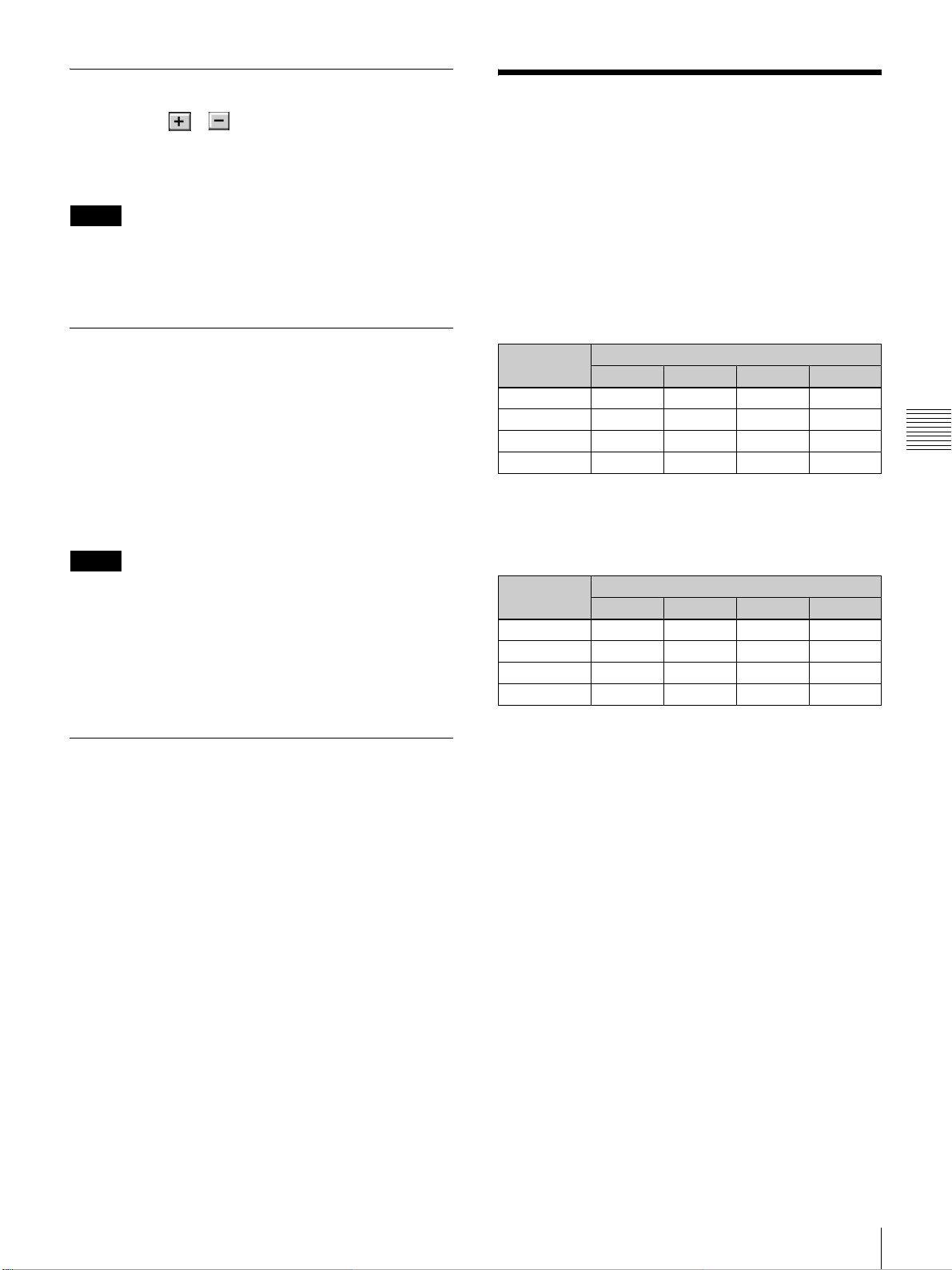
入力信号と調整・設定項
目
「PICTURECONTROL」画面の [SignalAdjust] と、
「COLOR/FRAME」画面の [FrameAdjust] の項目で、入力
信号によっては調整・設定できない項目があります。調
整・設定できない項目は画面に表示されません。
SignalAdjust
TESTPATTERN(テストパターン)
本機に内蔵のテストパターンをスクリーンに表示し、他機
からの信号を入力せずに画像の調整ができます。[Cross
Hatch(クロスハッチ)]、[CrossHatch(Invert)(イン
バートクロスハッチ)]、[CheckerFlag(チェッカーフラ
グ)]、[Testmode1(全白パターン)] から希望のテストパ
ターンのラジオボタンをクリックします。
テストパターンを表示しないときは、[Off] ラジオボタンを
クリックします。
ご注意
• 内蔵のテストパターン表示中は、INPUTSELECT ラジオ
ボタンの切り換え、PICTURECONTROL の調整はでき
ません。
• [Single3D] は 3D 画像を映すときに使用します。詳しくは、
お買い上げ店またはソニーのサービス窓口にお問い合わ
せください。
SINGLE3DADJUST(シングル 3D
調整)
項目
Contrast ○○○○
Brightness○○○○
Color ○×○×
Sharpness ○×××
○:調整・設定できる項目
×:調整・設定できない項目
FrameAdjust
項目
DotPhase ××××
HSize ××××
HShift ○○××
VShift ○○××
○:調整・設定できる項目
×:調整・設定できない項目
HD-SDI DVI-D HDMI 4K
HD-SDI DVI-D HDMI 4K
入力信号
入力信号
第 4 章 SRXController で行う調整と設定
3D 画像を映すときに使用します。
詳しくは、お買い上げ店またはソニーのサービス窓口にお
問い合わせください。
入力信号と調整・設定項目
27
Page 28
5
その他
ランプ交換の目安
光源のランプの推奨使用時間は、約 600 時間です。
「ControlFunctionMenu」画面の インジケーターのバー
が推奨使用時間に近づくと赤く表示されます。また、推奨使
用時間に対する現在の使用時間の割合(%)を表示します。
目安としてご使用ください。
ランプの交換は、お買い上げ店またはソニーのサービス窓
第 5 章 その他
口にご依頼ください。
第章
28
ランプ交換の目安
Page 29
故障かな?と思ったら
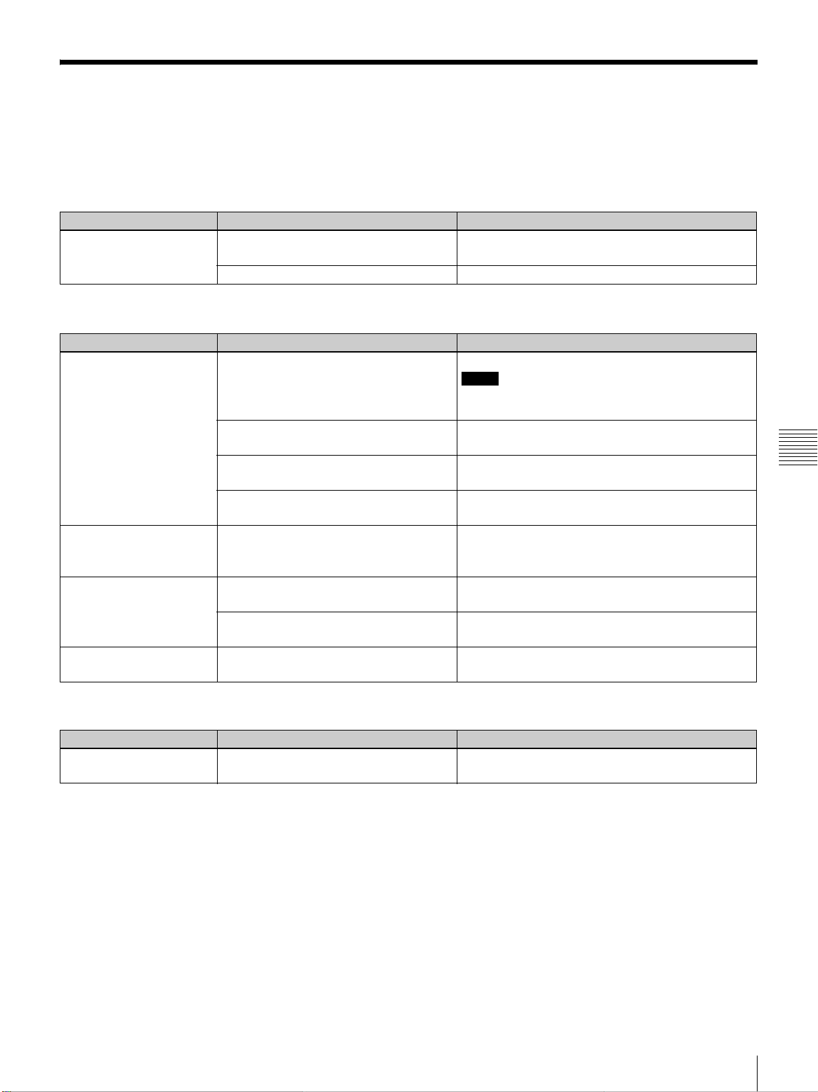
修理に出す前に、もう一度次の点検をしてください。
以下の対処を行っても直らない場合は、お買い上げ店またはソニーのサービス窓口にお問い合わせください。
電源に関する項目
症状 原因 対処
電源が入らない。 主電源が入っていない。 本体後面の電源スイッチをオン側(?)にしてください。(19
ページ)
本機とコントロール用 PC の接続がはずれている。 接続ケーブルをしっかり接続してください。(14 ページ)
映像に関する項目
症状 原因 対処
映像が映らない。 接続ケーブルがはずれている。 接続を確認してください。(17 ページ)
ご注意
本体への接続ケーブルの接続は、お買い上げ店またはソニーの
サービス窓口にご依頼ください。
入力が正しく選択されていない。 「SCREENCONTROL」画面の INPUTSELECT ラジオボタン
が正しく選択されているか確認してください。(20 ページ)
映像がミューティングされている。 「SCREENCONTROL」画面の [MUTING] の [OFF] ボタンを
クリックしてください。(20 ページ)
周囲の温度が高い。 周囲の温度が本機の使用温度範囲(5 〜 35 ℃)になるように、
室温調整をしてください。
色がおかしい。 入力信号モードが正しく設定されていない。 入力信号に合わせて、「PICTURECONTROL」画面で [Input
Source] の [SignalMode] を正しく設定してください。(23 ペー
ジ)
画面が暗い。 コントラスト、ブライトネスの設定が正しくない。「PICTURECONTROL」画面で [Contrast] と [Brightness] を正
しく設定してください。(24 ページ)
ランプ出力の設定が正しくない。 「INSTALLATION」画面の [LAMPPOWER] を正しく設定し
てください。(27 ページ)
4K 映像を映すと、中央に線が
表示される。
入力信号が 4K 映像に対応していない。 4K 映像を表示できる信号か確認してください。(20 ページ)
第 5 章 その他
コントロール系に関する項目
症状 原因 対処
「ControlFunctionMenu」画面
が表示されない。
本機とコントロール用 PC が正しく接続されてい
ない。
接続ケーブルを正しく接続してください。(14 ページ)
故障かな?と思ったら
29
Page 30
メッセージ
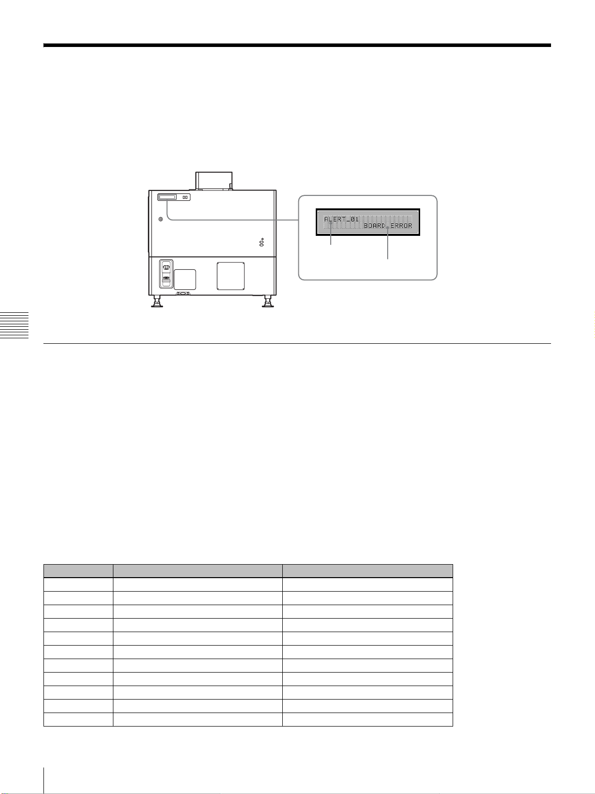
以下のメッセージが、本体後面の STATUSMESSAGE(ステータスメッセージ)表示窓に表示されます。
表示されるメッセージには、エラーが発生したことをお知らせするエラーメッセージと、情報を表示する情報メッセージがあ
ります。
エラーメッセージは、SRXController の「ControlFunctionMenu」画面の WarningInfo にも表示されます。
メッセージ番号
メッセージ
第 5 章 その他
エラーメッセージ
エラーメッセージは危険度に応じて下記の 3 種類に分けられています。
エラーが発生すると、表示窓にはメッセージ番号とエラーメッセージが表示されます。
ALERT(危険度:高)
メッセージ番号:ALERTxx
WARNING(危険度:中)
メッセージ番号:WARNxx
FAILURE(危険度:低)
メッセージ番号:FAILxx
エラーメッセージが表示された場合は、メッセージ番号とエラーメッセージをお買い上げ店またはソニーのサービス窓口にご
連絡ください。
ALERT(危険度:高)
メッセージ番号 エラーメッセージ 意味
ALERT01 BOARDERROR IFA 基板の通電故障
ALERT02 BOARDERROR IFB 基板の通電故障
ALERT03 BOARDERROR IFC 基板の通電故障
ALERT04 BOARDERROR IFD 基板の通電故障
ALERT05 BOARDERROR MX 基板の通電故障
ALERT06 BOARDERROR LPD 基板の通電故障
ALERT07 BOARDERROR CT 基板の通電故障
ALERT08 BOARDERROR DST 基板の通電故障
ALERT09 BOARDERROR PR1 基板の通電故障
ALERT10 BOARDERROR PR2 基板の通電故障
ALERT11 BOARDERROR SY 基板の通電故障
30
メッセージ
Page 31
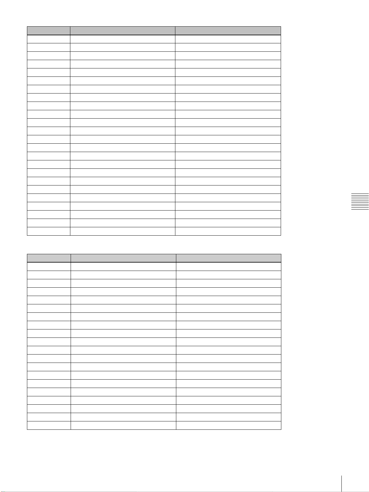
メッセージ番号 エラーメッセージ 意味
ALERT12 BOARDDETACHED CN 基板の抜け
ALERT13 BOARDDETACHED MX 基板の抜け
ALERT14 BOARDDETACHED LPD 基板の抜け
ALERT15 BOARDDETACHED CT 基板の抜け
ALERT16 BOARDDETACHED DST 基板の抜け
ALERT17 BOARDDETACHED PR1 基板の抜け
ALERT18 BOARDDETACHED PR2 基板の抜け
ALERT19 TEMPERATUREERROR R パネルの温度異常による停止
ALERT20 TEMPERATUREERROR G パネルの温度異常による停止
ALERT21 TEMPERATUREERROR B パネルの温度異常による停止
ALERT22 COVERDETACHED リア外装の外れ/内部ミラー位置の異常
ALERT27 FANERROR ランプ用ファン A の故障
ALERT28 FANERROR ランプ用ファン B の故障
ALERT29 FANERROR ランプ用ファン C の故障
ALERT30 FANERROR ランプ用ファン D の故障
ALERT32 BALLASTERROR ランプ電源の温度異常による停止
ALERT33 BALLASTERROR ランプ電源ファンの異常
ALERT34 BALLASTERROR ランプ電源の異常
ALERT35 LAMPERROR ランプ不点灯、または消灯
ALERT36 BALLASTERROR ランプ電源の異常
ALERT37 COVERDETACHED ランプハウスカバーの位置の異常
ALERT38 BOARDERROR CN 基板の通電故障
ALERT39 TEMPERATUREERROR 8 インチダクト部の温度異常による停止
ALERT41 COVERDETACHED フィルターダクトの外れによる停止
第 5 章 その他
WARNING(危険度:中)
メッセージ番号 エラーメッセージ 意味
WARN01 FANERROR セット電源ファン 1 の異常
WARN02 FANERROR セット電源ファン 2 の異常
WARN05 FANERROR 基板用ファン 1 の異常
WARN06 FANERROR 基板用ファン 2 の異常
WARN12 FANERROR ペルチェ R 用ファンの異常
WARN13 FANERROR ペルチェ G 用ファンの異常
WARN14 FANERROR ペルチェ B 用ファンの異常
WARN20 DEVICEERROR ペルチェ R の動作制御不能
WARN21 DEVICEERROR ペルチェ G の動作制御不能
WARN22 DEVICEERROR ペルチェ B の動作制御不能
WARN23 CONNECTORDETACHED ペルチェ R のコネクター抜け
WARN24 CONNECTORDETACHED ペルチェ G のコネクター抜け
WARN25 CONNECTORDETACHED ペルチェ B のコネクター抜け
WARN26 DOUSERERROR ダウザーの動作異常
WARN27 BALLASTERROR ランプ電源の通信異常
WARN28 BALLASTERROR ランプ S/N の誤設定
WARN30 COVERDETACHED フィルターダクトの外れ
WARN31 FANERROR PS2 用ファンの異常
WARN32 FANERROR PS1 用ファンの異常
WARN33 FANERROR PBS 用ファンの異常
メッセージ
31
Page 32
FAILURE(危険度:低)
メッセージ番号 エラーメッセージ 意味
FAIL02 TEMPERATUREERROR 8インチダクト部の温度異常の警告
FAIL04 TEMPERATUREERROR 吸気口の温度異常
FAIL06 TEMPERATUREERROR 光学ユニット部の温度異常
FAIL10 TEMPERATUREERROR R パネルの温度異常の警告
FAIL11 TEMPERATUREERROR G パネルの温度異常の警告
FAIL12 TEMPERATUREERROR B パネルの温度異常の警告
FAIL15 TEMPERATUREERROR ランプ電源の温度異常の警告
FAIL16 LENSERROR ZOOM メモリーの位置未到達
FAIL17 LENSERROR FOCUS メモリーの位置未到達
FAIL18 LENSERROR ZOOM 動作の異常
FAIL19 LENSERROR FOCUS 動作の異常
FAIL21 ADJUSTMENTERROR Z 軸の動作異常
FAIL25 DEVICEERROR FPGA コンフィグレーションの失敗
FAIL26 DEVICEERROR IIC の異常
FAIL27 DEVICEERROR LVDS の異常
FAIL28 DEVICEERROR PLL の異常
FAIL29 DEVICEERROR PARITY の異常
FAIL30 BALLASTERROR ランプ電源がインターロックしたとき
FAIL36 DEVICEERROR DVI の設定エラー
第 5 章 その他
情報メッセージ
情報メッセージにはメッセージ番号はありません。情報メッセージが表示されたら下記をご確認ください。
メッセージ 意味
LOWREALTIMECLOCKBATTERY SY 基板のボタン電池(BT200)の交換が必要です。
LAMPALERT ランプの推奨使用時間が過ぎました。
AIRFILTERWARNINGOPTICAL 光学用エアフィルターの推奨使用時間が過ぎました。
32
メッセージ
Page 33
本機の性能を保持するた
めに
アフターサービス
調子が悪いときはまずチェックを
異常音について
本機の内部には温度上昇を防ぐためにファンが取り付けら
れており、電源を入れると多少音を生じます。しかし、異
常音が発生した場合にはお買い上げ店にご相談ください。
部屋の照明について
直射日光や室内灯などで直接スクリーンを照らさないでく
ださい。美しく見やすい画像にするために、以下の点を参
考にしてください。
• 集光形のダウンライトにする。
• 蛍光灯のような散光照明にはメッシュを使用する。
• 太陽の差し込む窓はカーテンやブラインドでさえぎる。
• 光を反射する床や壁はカーペットや壁紙でおおう。
お手入れについて
• キャビネットやパネルの汚れは、柔らかい布で軽くふき
取ってください。汚れがひどいときには、水でうすめた
中性洗剤に柔らかい布をひたし、固くしぼってから汚れ
をふき取り、乾いた布で仕上げてください。なお、お手
入れの際は必ず電源スイッチを切ってください。
• レンズに手を触れたり、固いもので傷をつけたりしない
ようにご注意ください。
この説明書をもう一度ご覧になってお確かめください。
それでも具合の悪いときはお買い上げ店またはお近くのソ
ニーサービス窓口にご相談ください。
アフターサービスについてご不明な点は、お買い上げ店ま
たはお近くのソニーサービス窓口にお問い合わせください。
第 5 章 その他
定期点検について
本機の構成部品には、使用時間によって消耗する消耗部品
があります。
長期間本機を使用していただくため、定期的に点検を行っ
てください。定期点検にはサービスメンテナンス契約を結
ぶことをおすすめします。サービスメンテナンス契約につ
いては、お買い上げ店またはソニーのサービス窓口にご相
談ください。
本機の性能を保持するために/アフターサービス
33
Page 34
仕様
光学系
投影方式 SXRD(SiliconX-talReflectiveDisplay)
3 板式プリズム色分解合成方式
SXRD 8,847,360 画素(水平 4096 ×垂直 2160 × 3)
レンズ 別売
光出力 23,000lm(center)
30,000lm(center、HBM 時
ランプ 4.2kW キセノンランプ(別売)
1) 付属の HightBrightnessMode フィルターを使用した場合です。
(◆詳しくは、お買い上げ店またはソニーのサービス窓口にお問
い合わせください。)
電気系
対応信号 XGA、Quad-VGA、SXGA、SXGA+、UXGA、
WUXGA、1920 × 1080、2048 × 1080(HDCP
DVIインプットボード LKRI-005 装着時)
HD-SDI(SMPTE 規格信号)(HD-SDI(4:4:4)イン
第 5 章 その他
プットボード LKRI-003 装着時)
入/出力
DVI-D DVI コネクター 24 ピン(凸)(◆「ピン配列」参照
(35 ページ))
AUX DVI コネクター 24 ピン(凸)(◆「ピン配列」参照
(35 ページ))
RS-232C
ETHERNET 10BASE-T/100BASE-T
D-sub9 ピン(凹)(◆「ピン配列」参照(35 ページ))
受信信号
標準装備 XGA、Quad-VGA、SXGA、SXGA+、UXGA、
WUXGA、1920 × 1080、2048× 1080
LKRI-003 装着時
SMPTEFormatHD-SDI/DC-SDI/Dual-linkHD-SDI/
Dual-linkDC-SDI
LKRI-005 装着時
XGA、Quad-VGA、SXGA、SXGA+、UXGA、
WUXGA、1920 × 1080、2048× 1080
一般
外形寸法 約 700 × 640 × 1250mm(幅/高さ/奥行き)(別売
のレンズや本体突起部含まず)
質量 約 181kg(別売のレンズ、ランプ含まず)
電源 AC200V 〜 240V、50/60Hz
消費電力 最大約 5.6kW(スタンバイモード時 :29W)
消費電流 28 A 〜 23.4 A
動作温度 5 ℃〜 35 ℃(より良い画質を提供するため、約 20 分
間のエージングを推奨)
1)
)
性能保証温度
10 ℃〜 30 ℃
動作湿度 35% 〜 85%(結露なきこと)
保存温度 −20 ℃〜+60 ℃
保存湿度 10% 〜 90%
付属品 イーサネットケーブル
(1-830-803-12(Sony))(1)
レンズカバー(1 組)
レンズ取り付け用 M8 ネジ(4)
LKRI-003 用取り付け板(4)
LKRI-005 用取り付け板(3)
カギ(4)
HighBrightnessMode フィルター(1 組)
取扱説明書(本書、1)
この装置は、クラス A 情報技術装置です。この装置を
家庭環境で使用すると電波妨害を引き起こすことがあり
ます。この場合には使用者が適切な対策を講ずるよう要
求されることがあります。
VCCI-A
別売アクセサリー
プロジェクションランプバルブ
LKRX-2042A
HD-SDI(4:4:4)インプットボード
LKRI-003(HD-SDI:4BNC 型)
HDMI インプットボード
LKRI-006
HDCPDVI インプットボード
LKRI-005(2DVI-D 端子)
プロジェクションレンズ
LKRL-Z140、LKRL-Z211、LKRL-Z214、LKRL-Z219、
LKRL-A002、LKRL-A003、LKRA-005、LKRA-006
(◆詳しくは、それぞれのレンズの取扱説明書をご覧
ください。)
3D フィルター
LKRA-005、LKRA-006
仕様および外観は改良のため予告なく変更することがありますが、
ご了承ください。
• お使いになる前に、必ず動作確認を行ってください。
故障その他に伴う営業上の機会損失等は保証期間中お
よび保証期間経過後にかかわらず、補償はいたしかね
ますのでご了承ください。
• 本製品を使用したことによるお客様、または第三者か
らのいかなる請求についても、当社は一切の責任を負
いかねます。
• 諸事情による本製品に関連するサービスの停止、中断
について、一切の責任を負いかねます。
34
仕様
Page 35
ピン配列
RS-232C 端子(D-sub9 ピン、凹)
12345
6789
ピン番号 信号名 意味
1NC
2RD 受信
3TD 送信
4DTR
5GND 接地
6 DSR
7RTS
8CTS
9NC
1) 4-6 間はセット内部でショートしてあります。
2)
7-8 間はセット内部でショートしてあります。
DVI-D 端子、AUX 端子(24 ピン、凸)
1
9
17
ピン番号 信号名
1 DATA2 −
2 DATA2 +
3GND
4 DATA4 −
5 DATA4 +
6DDCSCL
7DDCSDA
8NC
9 DATA1 −
10 DATA1 +
11 GND
12 DATA3 −
13 DATA3 +
14 + 5V
15 DDCGND
16 HOTPLUGDET
17 DATA0 −
18 DATA0 +
19 GND
20 DATA5 −
21 DATA5 +
22 GND
23 CLK +
1)
1)
2)
2)
2
3
4
5
10
11
18
19
6
12
13
14
20
21
22
データターミナルレディ
データセットレディ
送信要求
送信可
7
8
15
16
23
24
ピン番号 信号名
24 CLK −
プリセット信号一覧
プリセット信号 fH
(kHz)fV(Hz)
HDTV 33.75 60.00 16:9
1024 × 768VESA60 48.36 60.00 4:3
1024 × 768VESA70 56.48 70.07 4:3
1024 × 768VESA75 60.02 75.03 4:3
1024 × 768VESA85 68.68 85.00 4:3
1280 × 960VESA60 60.00 60.00 4:3
1280 × 1024VESA60 63.97 60.01 5:4
1280 × 1024VESA75 79.98 75.03 5:4
1280 × 1024VESA85 91.15 85.02 5:4
1600 × 1200VESA60 75.00 60.00 4:3
720/60P 45.00 60.00 16:9
720/50P 37.50 50.00 16:9
1080/48I(24PsF) 27.00 48.00 16:9
1080/50I 28.13 50.00 16:9
108024P 27.00 24.00 16:9
DC2048 × 108048I 27.00 48.00 −
DC2048 × 108024P 27.00 24.00 −
1400 × 105060P 65.30 60.00 4:3
1920 × 108060P 67.50 60.00 16:9
1920 × 120060P 74.038 60.00 −
2048 × 108048P 54.00 48.00 −
2048 × 108060P 67.50 60.00 −
アスペクト比
マルチスクリーンモード時の画像表示サイズ
単位:dot(ドット)
スクリーン
信号名 水平 垂直 水平 垂直
XGA 2849 2137 1432 1074
SXGA1 2560 2048 1280 1024
SXGA2 2560 1920 1280 960
SXGA+ 2800 2100 1400 1050
1)
UXGA
WUXGA
720p 3810 2143 1916 1077
HD 3840 2160 1920 1080
2K 4096 2160 2048 1080
4K 4096 2160 − −
1) UXGA および WUXGA の信号は 4 画面モードで表示すると、
画像が一部欠けて表示されます。
全画面 4画面
モード
2864 2148 − −
1)
3437 2148 − −
第 5 章 その他
仕様
35
Page 36
索引
数字
3DResolutionFormat ..................... 23
4 画面モード .................................9,20
4K 信号を 4 画面モードで映す ........ 20
あ
アフターサービス ............................ 33
い
イーサネットケーブル..................... 14
色温度 .............................................. 25
インプットボード .......................23,24
え
映像反転........................................... 26
エラーメッセージ ............................ 30
第 5 章 その他
か
各部の名称と働き
後面............................................. 7
コントロールファンクション
メニュー画面........................... 8
前面/側面.................................. 7
カラー .............................................. 24
カラースペース................................ 24
カラー/フレーム画面..................... 24
ガンマ .............................................. 25
こ
故障かな?と思ったら..................... 29
コントラスト ................................... 24
コントロールファンクション
メニュー画面.............................8,22
し
シャープネス ................................... 24
仕様.................................................. 34
信号情報........................................... 23
信号調整......................................24,27
信号モード....................................... 23
す
垂直位置........................................... 25
水平位置........................................... 25
水平サイズ....................................... 25
ズーム .............................................. 26
スクイーズ....................................... 26
スクリーンコントロール画面 ............ 9
スクリーンに画像を映す..................19
ステータスメッセージ表示窓........... 30
せ
接続
HD-SDI 機器を接続する............17
コントロール用 PC を
接続する.................................14
PC を接続する(DVI-D 接続)...17
接続モード........................................16
設置設定画面....................................26
設定値を記憶する.............................22
設定値をリセットする......................22
て
テストパターン ................................27
と
ドットフェーズ ................................25
に
入力信号と調整・設定項目 ..............27
入力選択 .......................................9,20
入力ソース........................................23
は
排気口.................................................7
ひ
ピクチャーコントロール画面........... 23
ふ
フォーカス........................................26
付属品...............................................34
ブライトネス....................................24
プリセット信号一覧 .........................35
フレーム調整..............................25,27
プログラム・ランチャー画面........... 16
プログレッシブディスプレイ
モード ...........................................26
へ
別売アクセサリー.............................34
ほ
本機の性能を保持するために........... 33
ま
マスキング調整 ..................................9
マルチスクリーンモード時の
画像表示サイズ.............................35
め
メッセージ........................................30
ら
ランプインジケーター ................. 9,28
ランプ交換の目安 ............................ 28
ランプパワー.................................... 27
れ
レンズコントロール.........................26
B
Board.......................................... 23,24
Brightness ........................................ 24
C
Color................................................. 24
ColorSpace ...................................... 24
ColorTemp...................................... 25
COLOR/FRAME 画面..................... 24
Contrast ........................................... 24
ControlFunctionMenu 画面 ....... 8,22
CUTOFF ........................................ 10
D
DotPhase......................................... 25
E
ELECTRICSHIFTFUNCTION ..... 26
F
fH ..................................................... 23
Focus................................................ 26
FrameAdjust ............................ 25,27
FUNCTION1 〜 7 ........................... 22
fV ..................................................... 23
G
Gamma ............................................. 25
H
HShift.............................................. 25
HSize............................................... 25
I
I/PMode.......................................... 23
IMAGEFLIP ................................... 26
InputSource ....................................23
INSTALLATION 画面 .................... 26
L
LAMPPOWER................................ 27
LENSCONTROL ............................ 26
M
MASKINGADJUST.......................... 9
MUTING.................................... 10,20
36
索引
Page 37
O
OperationTimer................................ 8
P
PICTURECONTROL 画面 ............. 23
PROGRESSIVEDISPLAY
MODE .......................................... 26
Q
Quad-screenMode........................9,20
R
RS-232C 端子...............................15,35
S
SaveLog............................................ 8
SCREENCONTROL 画面................. 9
Sharpness......................................... 24
SignalAdjust ..............................24,27
SignalInfo........................................ 23
SignalMode..................................... 23
SQUEEZE........................................ 26
SRXController をインストール
する .............................................. 12
SRXController を起動する ............. 15
SRXController を終了する ............. 16
SRXController 画面で行う調整と
設定 .............................................. 22
STATUSMESSAGE 表示窓 ........7,30
T
TESTPATTERN ........................... 27
V
VShift.............................................. 25
Z
Zoom ................................................ 26
商標について
• Microsoft、Windows、Windows
Vista は、米国 Microsoft
Corporation の米国およびその他の
国における登録商標または商標で
す。
• Intel、Pentium は、アメリカ合衆国
および他の国におけるインテルコー
ポレーションの登録商標です。
• HDMI、HDMIHigh-Definition
MultimediaInterface および HDMI
ロゴは、HDMILicensingLLC の商
標もしくは米国およびその他の国に
おける登録商標です。
• その他、本書に記載されているシス
テム名、製品名は、一般に各開発
メーカーの登録商標あるいは商標で
す。
なお、本文中では ™、® マークは明記
していません。
第 5 章 その他
• 権利者の許諾を得ることなく、本
機に付属の取扱説明書の内容の全
部または一部を複製することは、
著作権法上禁止されております。
• 本機を使用したことによって生じ
た損害、逸失利益、および第三者
からのいかなる請求等につきまし
ても、当社は一切その責任を負い
かねます。
• 本機の仕様は、改良のため予告な
く変更することがありますが、ご
容赦ください。
索引
37
Page 38
English
Before operating the unit, please read this manual
thoroughly and retain it for future reference.
Owner’s Record
The model and serial numbers are located on the rear.
Record these numbers in the spaces provided below.
Refer to these numbers whenever you call upon your Sony
dealer regarding this product.
Model No.
Serial No.
WARNING
To reduce the risk of fire or electric shock,
do not expose this apparatus to rain or
moisture.
To avoid electrical shock, do not open the
cabinet. Refer servicing to qualified
personnel only.
For the customers in Canada
CAN ICES-3 (A)/NMB-3(A)
For the customers in Europe, Australia and New
Zealand
WARNING
This is a Class A product. In a domestic environment, this
product may cause radio interference in which case the
user may be required to take adequate measures.
For the customers in Europe
This product has been manufactured by or on behalf of
Sony Corporation, 1-7-1 Konan Minato-ku Tokyo, 1080075 Japan. Inquiries related to product compliance based
on European Union legislation shall be addressed to the
authorized representative, Sony Deutschland GmbH,
Hedelfinger Strasse 61, 70327 Stuttgart, Germany. For any
service or guarantee matters, please refer to the addresses
provided in the separate service or guarantee documents.
This apparatus shall not be used in the residential area.
For kundene i Norge
Dette utstyret kan kobles til et IT-strømfordelingssystem.
WARNING
THIS APPARATUS MUST BE EARTHED.
For the customers in the U.S.A.
This equipment has been tested and found to comply with
the limits for a Class A digital device, pursuant to part 15
of the FCC Rules. These limits are designed to provide
reasonable protection against harmful interference when
the equipment is operated in a commercial environment.
This equipment generates, uses, and can radiate radio
frequency energy and, if not installed and used in
accordance with the instruction manual, may cause
harmful interference to radio communications. Operation
of this equipment in a residential area is likely to cause
harmful interference in which case the user will be
required to correct the interference at his own expense.
You are cautioned that any changes or modifications not
expressly approved in this manual could void your
authority to operate this equipment.
All interface cables used to connect peripherals must be
shielded in order to comply with the limits for a digital
device pursuant to Subpart B of part 15 of FCC Rules.
For the State of California, USA only
Perchlorate Material - special handling may apply, See
www.dtsc.ca.gov/hazardouswaste/perchlorate
For the customers in Taiwan only
AVERTISSEMENT
Afin de réduire les risques d’incendie ou
d’électrocution, ne pas exposer cet
appareil à la pluie ou à l’humidité.
Afin d’écarter tout risque d’électrocution,
garder le coffret fermé. Ne confier
l’entretien de l’appareil qu’à un personnel
qualifié.
This device complies with part 15 of the FCC Rules.
Operation is subject to the following two conditions:
(1) This device may not cause harmful interference, and
(2) this device must accept any interference received,
including interference that may cause undesired operation.
38
AVERTISSEMENT
CET APPAREIL DOIT ÊTRE RELIÉ À LA
TERRE.
Pour les clients au Canada
CAN ICES-3 (A)/NMB-3(A)
Page 39
Pour les clients en Europe, Australie et NouvelleZélande
AVERTISSEMENT
Il s’agit d’un produit de Classe A. Dans un environnement
domestique, cet appareil peut provoquer des interférences
radio, dans ce cas l’utilisateur peut être amené à prendre
des mesures appropriées.
Pour les clients en Europe
Ce produit a été fabriqué par ou pour le compte de Sony
Corporation, 1-7-1 Konan Minato-ku Tokyo, 108-0075
Japon. Toutes les questions relatives à la conformité des
produits basées sur la législation européenne doivent être
adressées à son représentant, Sony Deutschland GmbH,
Hedelfinger Strasse 61, 70327 Stuttgart, Allemagne.
Pour toute question relative au Service Après-Vente ou à
la Garantie, merci de bien vouloir vous référer aux
coordonnées qui vous sont communiquées dans les
documents « Service (SAV) » ou Garantie.
Ne pas utiliser cet appareil dans une zone résidentielle.
WARNUNG
Um die Gefahr von Bränden oder
elektrischen Schlägen zu verringern, darf
dieses Gerät nicht Regen oder
Feuchtigkeit ausgesetzt werden.
Um einen elektrischen Schlag zu
vermeiden, darf das Gehäuse nicht
geöffnet werden. Überlassen Sie
Wartungsarbeiten stets nur qualifiziertem
Fachpersonal.
WARNUNG
DIESES GERÄT MUSS GEERDET
WERDEN.
bitte den Bevollmächtigten Sony Deutschland GmbH,
Hedelfinger Strasse 61, 70327 Stuttgart, Deutschland. Für
Kundendienst oder Garantieangelegenheiten wenden Sie
sich bitte an die in den Kundendienst- oder
Garantiedokumenten genannten Adressen.
Dieser Apparat darf nicht im Wohnbereich verwendet
werden.
For the customers in the U.S.A.
SONY LIMITED WARRANTY
http://www.sony.com/psa/warranty
information and complete terms and conditions of Sony’s
limited warranty applicable to this product.
For the customers in Canada
SONY LIMITED WARRANTY
http://www.sonybiz.ca/solutions/Support.do
important information and complete terms and conditions
of Sony’s limited warranty applicable to this product.
For the customers in Europe
Sony Professional Solutions Europe - Standard Warranty
and Exceptions on Standard Warranty.
Please visit http://www.pro.sony.eu/warranty
important information and complete terms and
conditions.
For the customers in Korea
SONY LIMITED WARRANTY
http://bpeng.sony.co.kr/handler/BPAS-Start
important information and complete terms and conditions
of Sony’s limited warranty applicable to this product.
Pour les clients au Canada
GARANTIE LIMITÉE DE SONY
http://www.sonybiz.ca/solutions/Support.do
les informations importantes et l’ensemble des termes et
conditions de la garantie limitée de Sony applicable à ce
produit.
- Please visit
for important
- Please visit
for
for
- Please visit
for
- Rendez-vous sur
pour obtenir
GB
Für Kunden in Europa, Australien und
Neuseeland
WARNUNG
Dies ist eine Einrichtung, welche die Funk-Entstörung
nach Klasse A besitzt. Diese Einrichtung kann im
Wohnbereich Funkstörungen verursachen; in diesem Fall
kann vom Betreiber verlangt werden, angemessene
Maßnahmen durchzuführen und dafür aufzukommen.
Für Kunden in Europa
Dieses Produkt wurde von oder für Sony Corporation, 1-71 Konan Minato-ku Tokio, 108-0075 Japan hergestellt.
Bei Fragen zur Produktkonformität auf Grundlage der
Gesetzgebung der Europäischen Union kontaktieren Sie
39
Page 40

Table of Contents
Projecting a 4K Signal in Quad-Screen
Mode.................................................. 56
Chapter 1 Overview
Precautions................................................41
On Viewing 3D Video Images...................43
Location and Function of Controls..........43
Projector Unit.............................................. 43
Control Function Menu Window................ 44
Chapter 2 Preparations
Precautions on Installation ......................47
Unsuitable Installation................................ 47
Unsuitable Conditions ................................ 48
Installing the SRX Controller in a
Computer for Controlling the
Projector..............................................48
Operating Environment .............................. 48
Installing the SRX Controller..................... 49
Connecting a Computer for Controlling
the Projector .......................................50
Connecting the Computer via the
Ethernet ............................................. 50
Connecting the Computer via the
RS-232C............................................ 51
Starting the SRX Controller......................52
Turning On the Main Power of the
Projector ............................................ 52
Starting SRX Controller ............................. 52
Changing the Connection Mode ................. 53
Connecting the Projector .........................53
Connecting a Computer Equipped with a
DVI-D Connector.............................. 53
Connecting HD-SDI Equipment................. 54
Connecting HDMI Equipment.................... 54
Chapter 3 Projecting
Chapter 4 Adjustments and Settings
Using the SRX Controller
Displaying the Control Function Menu
Window................................................58
PICTURE CONTROL Window...................59
Board........................................................... 59
Input Source................................................ 59
3D Resolution Format................................. 59
Signal Info (Information)............................ 59
Signal Adjust .............................................. 60
COLOR/FRAME Window...........................60
Board........................................................... 60
Color ........................................................... 60
Frame Adjust .............................................. 61
INSTALLATION Window ...........................62
LENS CONTROL ...................................... 62
ELECTRIC SHIFT FUNCTION................ 62
IMAGE FLIP .............................................. 62
PROGRESSIVE DISPLAY MODE........... 62
SQUEEZE................................................... 62
LAMP POWER .......................................... 62
TEST PATTERN........................................ 63
SINGLE 3D ADJUST ................................ 63
Input Signals And Adjustable/
Setting Items.......................................63
Chapter 5 Others
Recommended Replacement Time..........64
Maintenance ..............................................64
Troubleshooting........................................65
Messages ...................................................66
Error Messages ........................................... 66
Information Messages................................. 68
Specifications............................................69
Index...........................................................72
Projecting the Picture ...............................55
40
Table of Contents
Page 41
Overview
Precautions
On safety
• Operate the unit on 200 V to 240 V AC, 50/60 Hz.
• Should any liquid or solid object fall into the cabinet,
unplug the unit and have it checked by your Sony dealer
before operating it further.
• Set the power switch to the lower position if it is not to
be used for several days.
• The unit is not disconnected from the AC power source
(mains) as long as it is connected to the wall outlet and
the power switch is set to the upper position.
• Do not look into the lens while the lamp is on.
• Do not place your hand or objects near the ventilation
holes. The air coming out is hot.
• Use a lifter to carry the projector to avoid accidents or
injury.
• Do not catch your finger between the unit and surface of
the floor when moving the projector installed on the
floor.
• Be careful not to catch your finger in the cooling fan.
• Since an intense light has come out of this projector from
the front, do not stand on the front of a projector for a
long time.
On installation
• Allow adequate air circulation to prevent internal heat
build-up. Do not place the unit on surfaces (rugs,
blankets, etc.) or near materials (curtains, draperies) that
may block the ventilation holes.
Leave space of more than 100 cm (39
between the wall and the projector. Be aware that room
heat rises to the ceiling; check that the temperature near
the installation location is not excessive.
• Install the projector on the floor or hang it from the
ceiling. Any other installation causes a malfunction such
as color irregularity or a shorten lamp life.
• Do not install the unit in a location near heat sources
such as radiators or air ducts, or in a place subject to
3
/8 inches)
Chapter
direct sunlight, excessive dust or humidity, mechanical
vibration or shock.
• To avoid moisture condensation, do not install the unit in
a location where the temperature may rise rapidly.
On illumination
• To obtain the best picture, the front of the screen should
not be exposed to direct lighting or sunlight.
• Ceiling-mounted spot lighting is recommended. Use a
cover over fluorescent lamps to avoid lowering the
contrast ratio.
• Cover any windows that face the screen with opaque
draperies.
• It is desirable to install the projector in a room where
floor and walls are not of light-reflecting material. If the
floor and walls are of reflecting material, it is
recommended that the carpet and wall paper be changed
to a dark color.
On preventing internal heat build-up
After turning off the power, the cooling fan runs for about
3 to 15 minutes by detecting an internal temperature while
the MAIN and LAMP indicators flash green.
Caution
The projector is equipped with ventilation holes (intake) at
the right side, and ventilation holes (exhaust) at the upper
and left sides.
Do not block or place anything near these holes, or internal
heat build-up may occur, causing picture degradation or
damage to the projector.
On cleaning
• To keep the cabinet looking new, periodically clean it
with a soft cloth. Stubborn stains may be removed with
a cloth lightly dampened with a mild detergent solution.
Never use strong solvents, such as thinner, benzene, or
abrasive cleansers, since these will damage the cabinet.
• Avoid touching the lens. To remove dust on the lens, use
a soft dry cloth. Do not use a damp cloth, detergent
solution, or thinner.
1
Chapter 1 Overview
Precautions
41
Page 42
On repacking
Save the original shipping carton and packing material;
they will come in handy if you ever have to ship your unit.
For maximum protection, repack your unit as it was
originally packed at the factory.
Chapter 1 Overview
On condensation
If the room temperature where the projector is installed
changes rapidly, or if the projector is moved suddenly from
a cold to a warm place, condensation in the projector may
occur. As the condensation may cause malfunction, be
careful in adjusting temperature settings of the air
conditioner. If condensation occurs, leave the projector
turned on for about two hours before use.
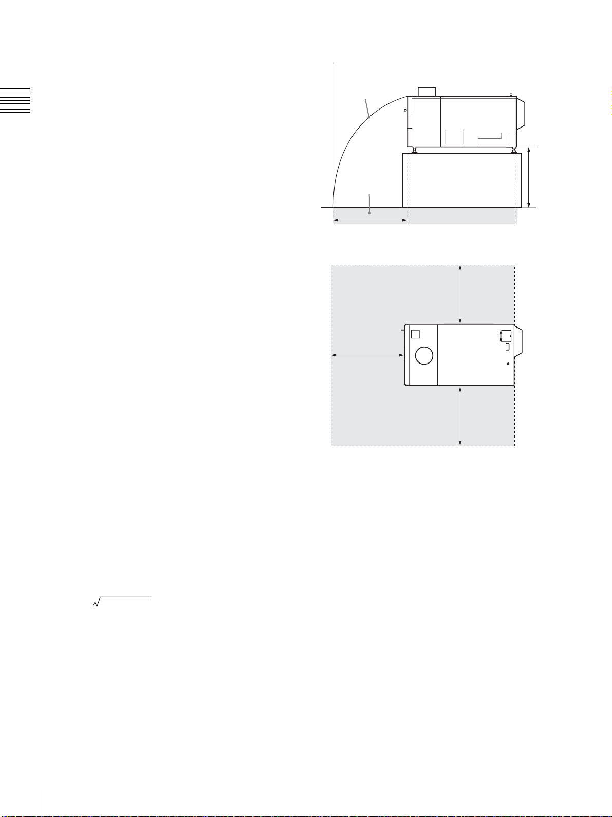
Left side view
Scatter parabolic
curve in a case of
lamp explosion
Danger radius in
a case of lamp
explosion
x
y
Floor
On the LCD projector
The LCD projector is manufactured using high-precision
technology. You may, however, see tiny black points and/
or bright points (red, blue, or green) that continuously
appear on the LCD projector. This is a normal result of the
manufacturing process and does not indicate a
malfunction.
Also, when you use multiple LCD projectors to project
onto a screen, even if they are of the same model, the color
reproduction among projectors may vary, since color
balance may be set differently from one projector to the
next.
On prohibiting continuous lighting
Continuously lighting the Xenon lamp for 24 hours will
reduce approximately half of its lamp life. Be sure to turn
off the lamp for an hour or more after continuously lighting
for 24 hours.
On dangerous areas in a case of lamp
explosion
Since a projector lamp can explode, it is dangerous to be in
the shaded areas shown in the illustrations below. Keep
away from the dangerous areas.
The danger radius (x) differs depending on the height (y)
between the bottom of the projector and the floor.
x = 20/3 × 10y + 6400
Top view
Danger radius in a case of
lamp explosion
x
x
x
For example, in a case where the height (y) is 800 mm
1
(31
/2 in.), the danger radius (x) calculated by the formula
above is 800 mm (31
42
Precautions
1
/2 in.)
Page 43
On Viewing 3D Video
Location and Function of
Images
• You should only use 3D glasses for viewing 3D video
images.
• You should only use 3D glasses that Sony recommends.
• Some people may experience discomfort (such as eye
strain, fatigue, or nausea) when viewing 3D video
images. In such a case, you must decide what works best.
If you experience any discomfort, you should
IMMEDIATELY stop viewing the 3D video images
until the discomfort ends. Consult a doctor if you believe
it necessary.
• The vision of young children (especially those under six
years old) is still under development. Consult your
doctor (such as a pediatrician or eye doctor) before
allowing young children to view 3D video images.
• Not for use by children without proper adult supervision.
• Adults should supervise young children to ensure that
they follow the recommendations listed above.
Controls
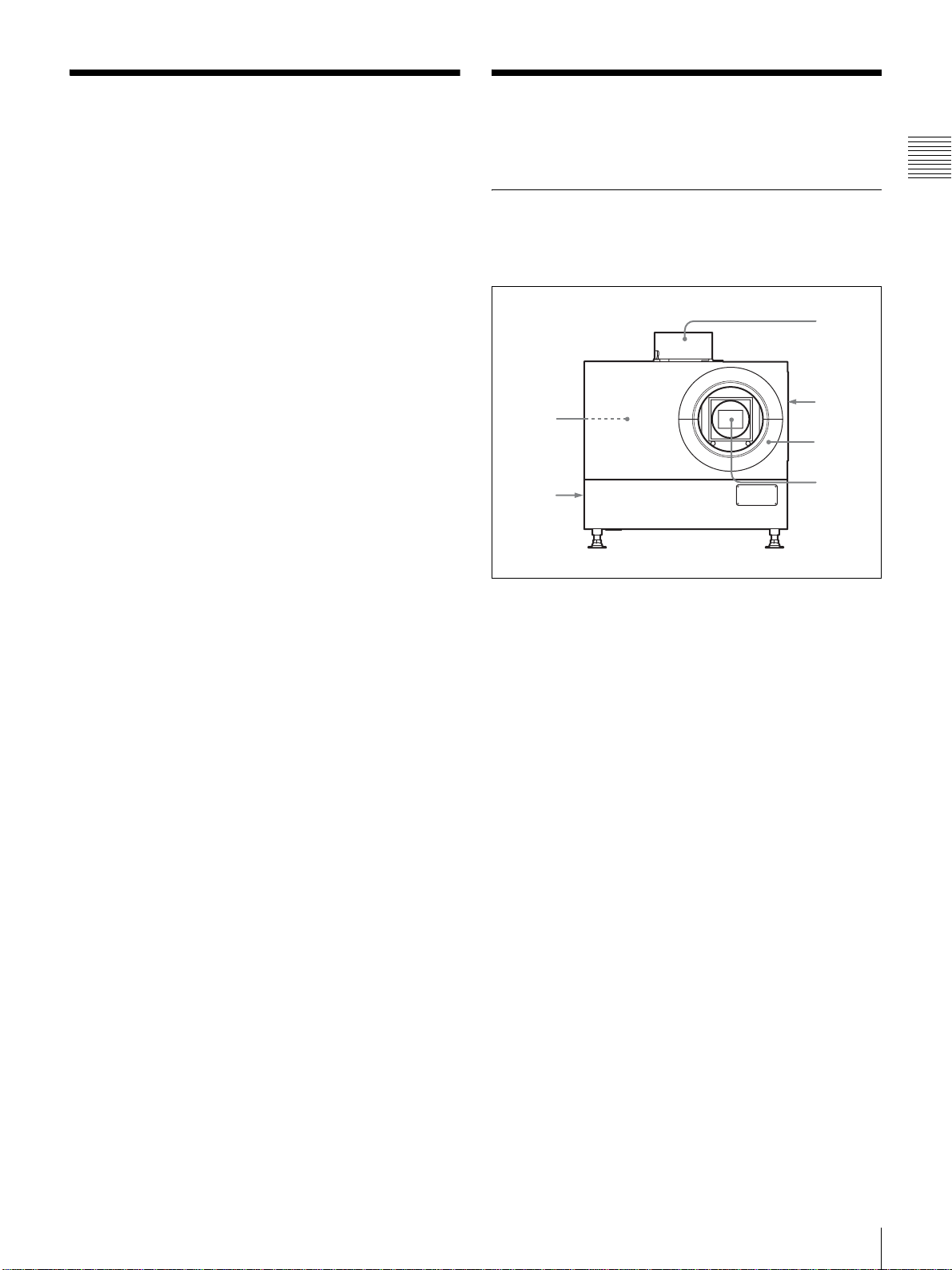
Projector Unit
Front/Sides
5
6
Chapter 1 Overview
1
2
3
4
a Upper side ventilation hole (exhaust)
b Ventilation holes (intake)/air filter (right side)
For replacement of an air filter, consult your dealer or your
local Sony representative.
c Lens cover
d Lens mount part
When attaching the optional lens, consult your dealer or
your local Sony representative.
e Input board attachment parts (inside the
projector)
Depending on the input sources, install the optional input
board in a slot inside the projector. For installation of the
board, consult your dealer or your local Sony
representative.
The input board slots are arranged in order of INPUT A,
INPUT B, INPUT C and INPUT D from right to left.
INPUT A is preinstalled with an LKRI-005 HDCP DVI
board. Depending on the input source, you can replace it
with an optional input board.
DVI-D connector (24-pin DVI connector, male): For
input of progressive DVI signals and HDCP-compatible
DVI signals.
AUX connector (24-pin DVI connector, male):
Used for input extension. For details, consult your dealer
or your local Sony representative.
On Viewing 3D Video Images / Location and Function of Controls
43
Page 44
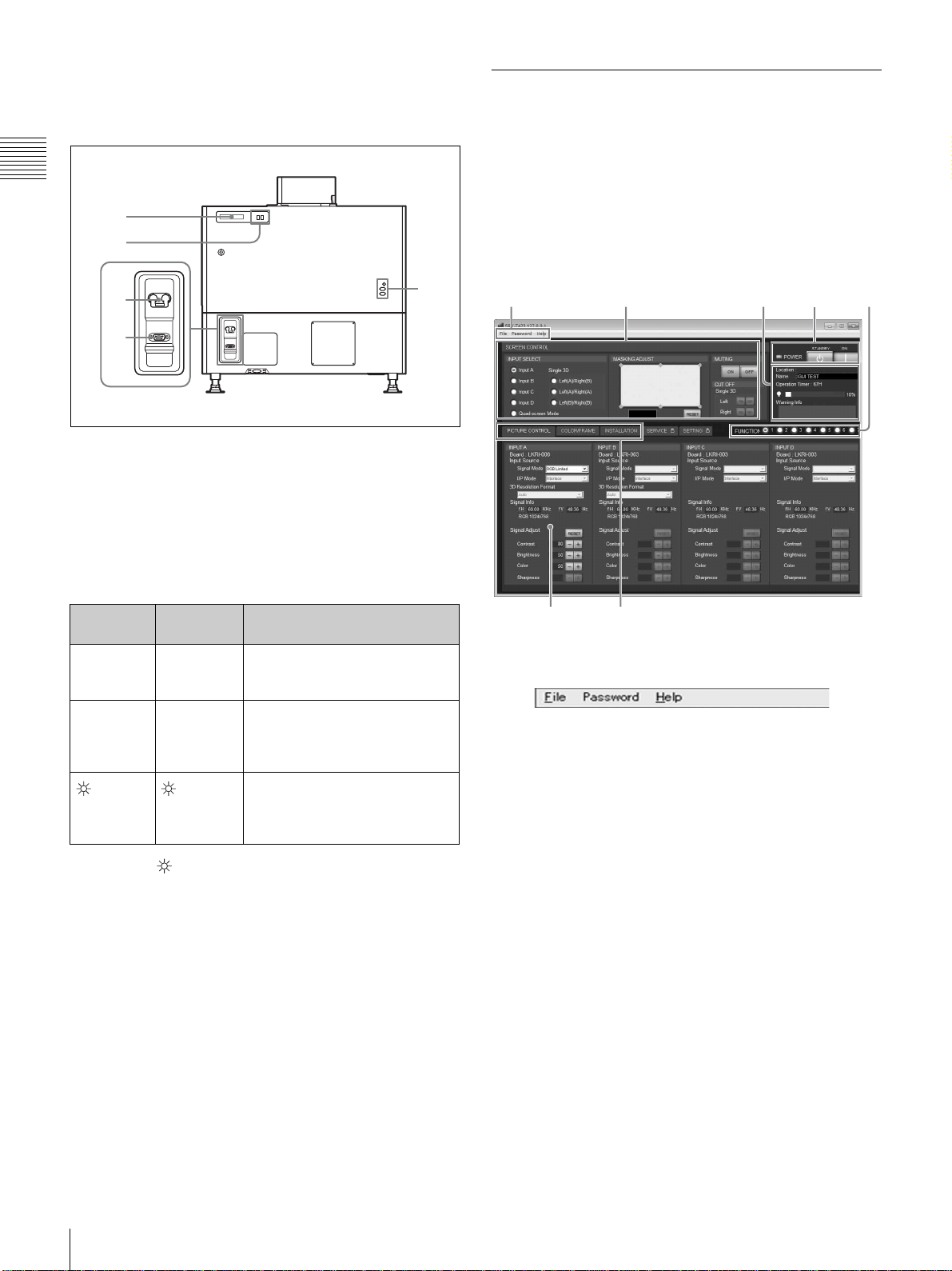
f Ventilation holes (exhaust) (left side)
1
6
2 3 4
67
Control Function Menu Window
Rear
Chapter 1 Overview
1
2
3
RS-232C
4
a STATUS MESSAGE window
Displays various messages.
For details on messages, see page 66.
b Status indicators
Combinations of the MAIN and LAMP indicators indicate
the status of the projector as follows:
5
When you install the SRX Controller in your computer, you
can operate all of the features of the projector in your
computer window. This section explains the functions of the
parts for projecting an image on the screen.
For the windows used for the settings and adjustments, see
“Adjustments and Settings Using the SRX Controller” on
page 58.
1
2345
MAIN
indicator
z (red) z (red) The projector is in standby
z (green) z (green) The projector is turned on with
(green) (green)
z: Lights : Flashes
LAMP
indictor
Status of the projector
mode. You can turn it on with the
SRX controller.
the SRX controller. You can
operate the projector with the
SRX controller.
The projector is in standby after
shutting it down with the SRX
controller. Cooling fans are
running.
c Power switch
Turns the projector’s main power on (:) or off (a).
d RS-232C connector (D-sub 9-pin, female)
Connect to the RS-232C connector on a computer in which
the supplied SRX Controller is installed. You can control
the projector from the computer.
e Lamp adjustment windows
The lamp adjustment screws are behind these windows.
Fine adjustment of lamp position is necessary after
replacing the lamp.
For lamp adjustment, contact your dealer or your local
Sony representative.
a Menu bar
File menu
Selecting [Quit] from the File menu exits the SRX
Controller.
Save Log: This item is for service use. For details, consult
your dealer or your local Sony representative.
Password menu
Used to reset the authentication passwords required for
displaying the SETTING window and the SERVICE
window. The Password menu can be displayed only when
an authorized administrator starts the SRX Controller on
the computer for controlling the projector.
For details on the SETTING window and the SERVICE
window, refer to the Installation Manual for Dealers.
Help menu
Shows the version information of the SRX Controller and
the serial number of the projector.
44
Location and Function of Controls
Page 45
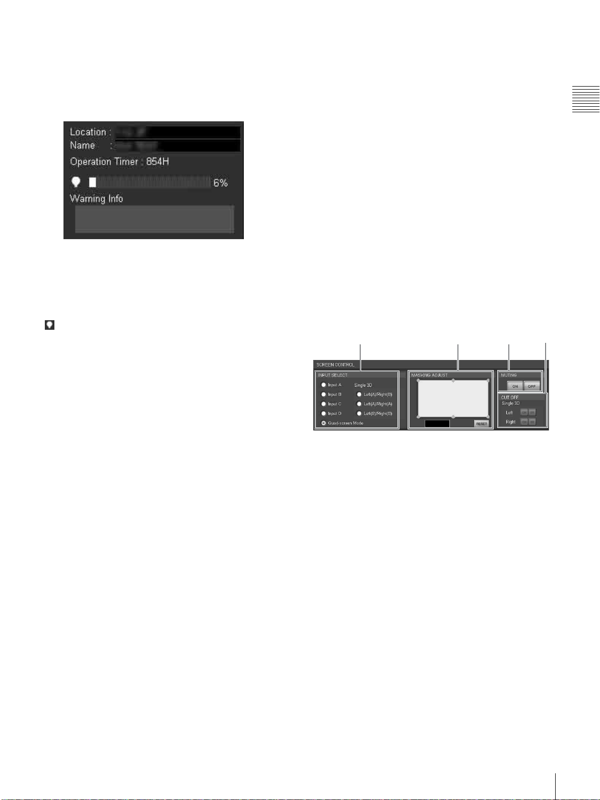
b SCREEN CONTROL window
1 2 4 5
For details, see “SCREEN CONTROL window” on page
45.
c Information window
Location: Shows the installation location of the projector
that was set in the SETTING window.
Name: Shows the name of the projector that was set in the
SETTING window.
Operation Timer: Shows the total operating hours (H) of
the projector.
indicator: The bar indicator and the value (%) indicate
the proportion of elapsed usage time to the
recommended time between replacements.
Warning Info: Displays an error message if there is any
warning information on the projector. The same
message is displayed in the STATUS MESSAGE
window at the rear side of the projector.
CONTROL] settings when the optional lens equipped
with zoom/focus memory function is installed, and [3D
Gamma Select] and [Position Adjust] of [SINGLE 3D
ADJUST] when 3D images are projected, in the
INSTALLATION window
For details, see “To register the settings that have been
adjusted” on page 58.
f Adjustment/setting window
Clicking the window select button switches the window
for the adjustment and setting.
The PICTURE CONTROL, COLOR/FRAME and
INSTALLATION windows can be displayed.
For details on each window, see “Adjustments and
Settings Using the SRX Controller” on page 58.
g Window select buttons
Open the window with the items you want to set or adjust.
SCREEN CONTROL window
123 4
Chapter 1 Overview
d POWER ON/STANDBY (?/1) buttons and
POWER indicator
Click [ON] to turn on the projector when the MAIN and
LAMP indicators at the rear of the projector are lit in red.
Both indicators and the POWER indicator on a computer
turn green, and you can operate the projector with the SRX
controller on the computer.
To turn off the projector, click [STANDBY] then click
[OK] in the displayed confirmation window. The projector
enters standby mode, and the indicator flashes green. Even
in standby mode, the fans continue to run to reduce internal
heat. When the fans stop running, the MAIN and LAMP
indicators light in red.
e FUNCTION 1 to 7 radio buttons
Register the data set or adjusted in the Control Function
Menu windows to these buttons, and recall it later to
project an image with that setting.
The setting items that can be registered are as follows:
• [INPUT SELECT], [MASKING ADJUST] and [CUT
OFF] settings in the SCREEN CONTROL window
• [Input Source] and [Signal Adjust] settings in the
PICTURE CONTROL window
• [Color] settings in the COLOR/FRAME window
• [ELECTRIC V SHIFT FUNCTION], [ELECTRIC H
SHIFT FUNCTION], [SQUEEZE], [PROGRESSIVE
DISPLAY MODE], [LAMP POWER] settings, [LENS
a INPUT SELECT radio buttons
Selects the input signal you want to project on the screen.
Input A: Selects the signal input from the connectors on
the preinstalled input board in the INPUT A section.
Input B: Selects the signal input from the connectors on
the optional input board installed in the INPUT B
section.
Input C: Selects the signal input from the connectors on
the optional input board installed in the INPUT C
section.
Input D: Selects the signal input from the connectors on
the optional input board installed in the INPUT D
section.
Quad-screen Mode: Selects when you project pictures
from each input sources from INPUT A to INPUT D
on one screen.
Single 3D buttons: Used for projecting 3D images. For
details, contact your dealer or your local Sony
representative.
b MASKING ADJUST section
You can mask the areas of unnecessary portions of the
screen.
Location and Function of Controls
45
Page 46
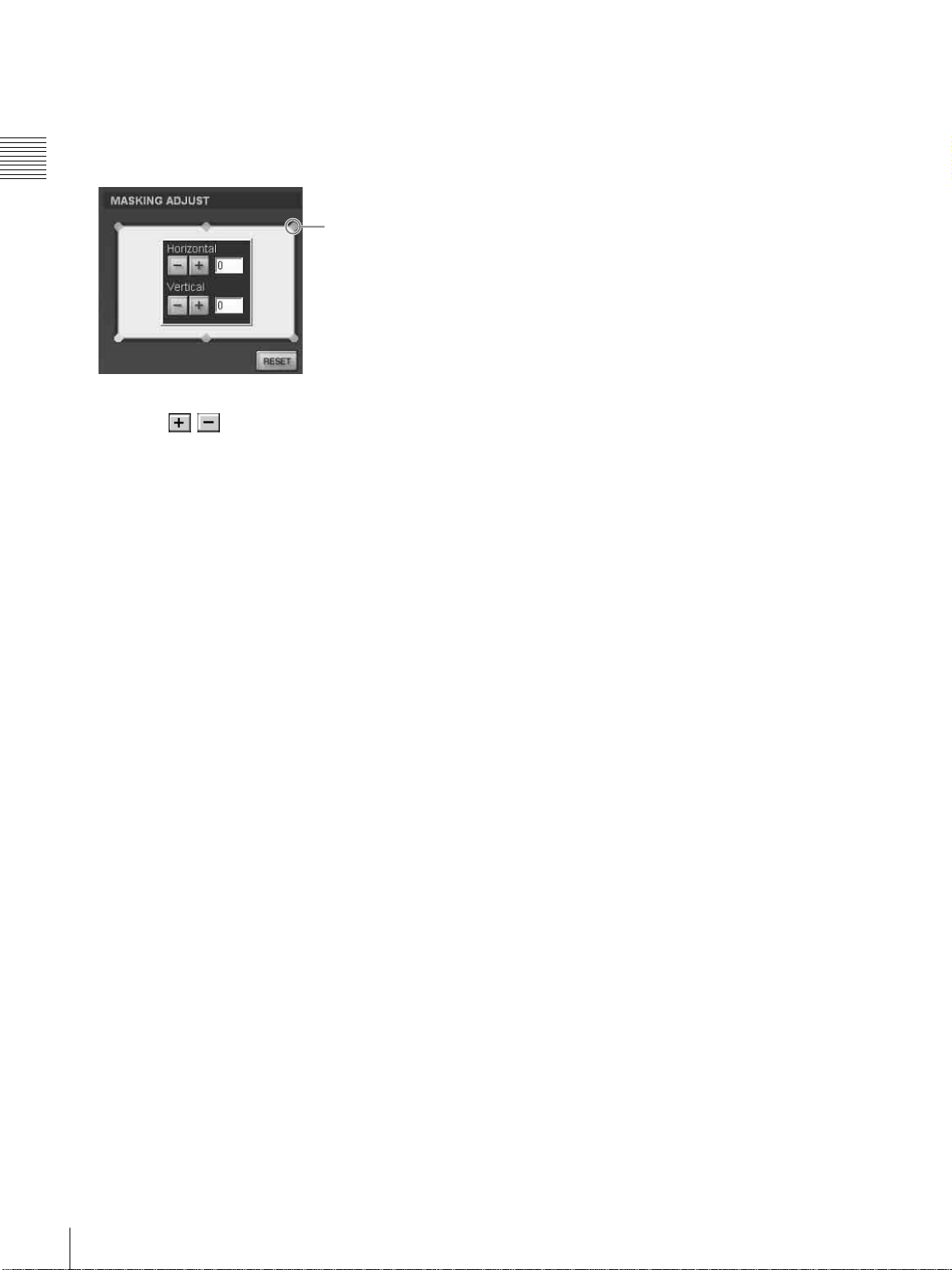
You can adjust the masking areas with each of six
adjustment points.
1 Double-click one of the adjustment points.
Chapter 1 Overview
Adjustment point
2 Adjust a masking area by clicking the [Horizontal] or
[Vertical] / buttons or by entering values in
both text boxes, while viewing the screen to check the
results.
The adjustment ranges for the values are 0 to 950 for
the four points at the corners and –500 to 500 for the
two points in the center.
3 Repeat steps 1 and 2 to adjust each point while viewing
the screen, and mask the screen as necessary.
Clicking the [RESET] button resets all the values to the
factory-preset settings.
The adjustment window opens.
c MUTING ON/OFF buttons
Clicking the [ON] button cuts off the whole picture on the
screen momentarily. Click the [OFF] button to restore the
picture. Activating the muting function blocks off lamp
light completely by use of a shutter, and displays the black
signal on the whole screen.
d CUT OFF ON/OFF buttons
Used for projecting 3D images. For details, contact your
dealer or your local Sony representative.
46
Location and Function of Controls
Page 47
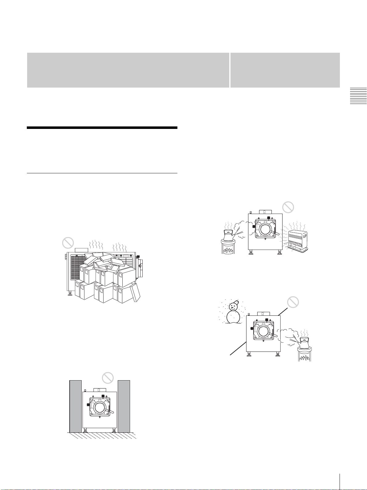
Preparations
Precautions on
Installation
Unsuitable Installation
Chapter
If you put something beside the ventilation holes for
exhaust on the side or rear of the projector, the exhaust
may be inhaled into the projector through the ventilation
holes for intake, causing internal heat build-up and thereby
activating the protection circuit. Be sure not to block the
ventilation holes for exhaust. Leave a space of more than
1m (39
3
/8 inches) around the unit.
2
Chapter 2 Preparations
Do not install the projector in the following situations.
Such installations may cause a malfunction or damage to
the projector.
Poorly ventilated
The projector is equipped with ventilation holes for intake
and exhaust to prevent internal heat build-up. Do not place
the projector in a place where the ventilation holes may be
blocked.
Situation that may block the ventilation
holes for exhaust
Extremely hot and humid
Location subject to sudden change of
temperature
A sudden change of temperature may produce moisture
condensation, causing damage to the projector. Take care
with heaters or air-conditioners.
Precautions on Installation
47
Page 48
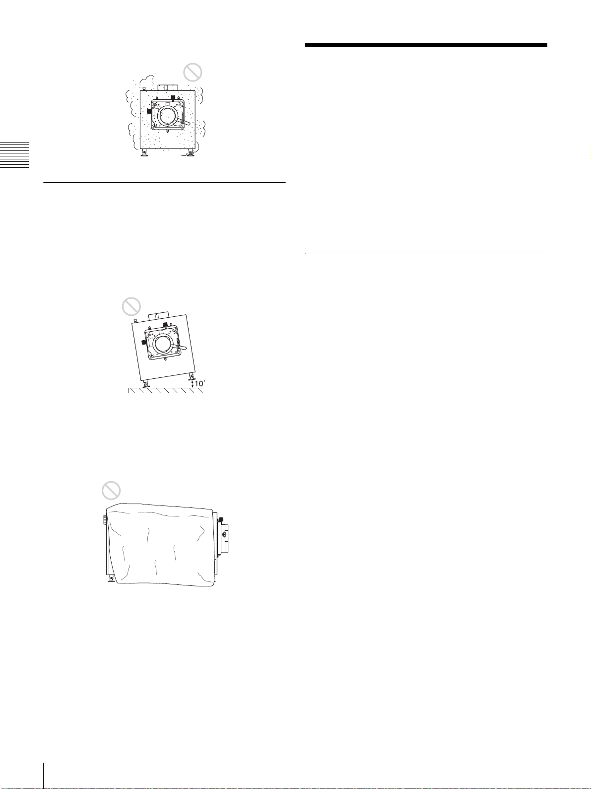
Very dusty
Installing the SRX
Controller in a Computer
for Controlling the
Projector
Chapter 2 Preparations
Unsuitable Conditions
Do not use the projector under the following conditions.
Laying the unit on its side or upside down
Tilting the unit to the right or left
Avoid tilting the projector more than ± 10 degrees. Doing
so may cause color shading or shorten the lamp life
excessively.
Blocking the ventilation holes
If you install the SRX Controller in a computer, you can
control the projector from the computer.
If a previous version of SRX Controller is already installed
on the computer, uninstall the previous version
beforehand.
Operating Environment
A computer that meets the following conditions is required
to operate SRX Controller.
Operating system (OS):
Windows Vista Business SP2 (English or Japanese
edition, excluding x64 edition)
Windows 7 Enterprise SP1 (English or Japanese
edition)
CPU: Intel Pentium M 1.6 GHz or higher,
OS-recommended CPU
Memory: 256 MB or higher (512 MB or higher
recommended), OS-recommended memory
Available HDD space: 15 MB or higher (internal drive)
Monitor: XGA (1024 × 768) or higher
Communication: LAN (10BASE-T/100BASE-TX) or
COM (RS-232C)
Avoid using a thick-piled carpet or anything that covers
the ventilation holes (exhaust/intake). Otherwise, internal
heat may build up.
For the locations of the ventilation holes (exhaust/intake),
see “Location and Function of Controls” on page 43.
48
Installing the SRX Controller in a Computer for Controlling the Projector
User Account Control of Windows Vista/7
Windows Vista/7 incorporates the User Account Control
(UAC) function for improving its security level. As the
SRX Controller supports the UAC function, the warning
dialog of UAC may be displayed during installation or
activation of application.
When the warning dialog is displayed, allow execution of
the application in the following procedure.
When the unidentified application dialog is
displayed
Select [Allow] to allow execution of the application.
Page 49
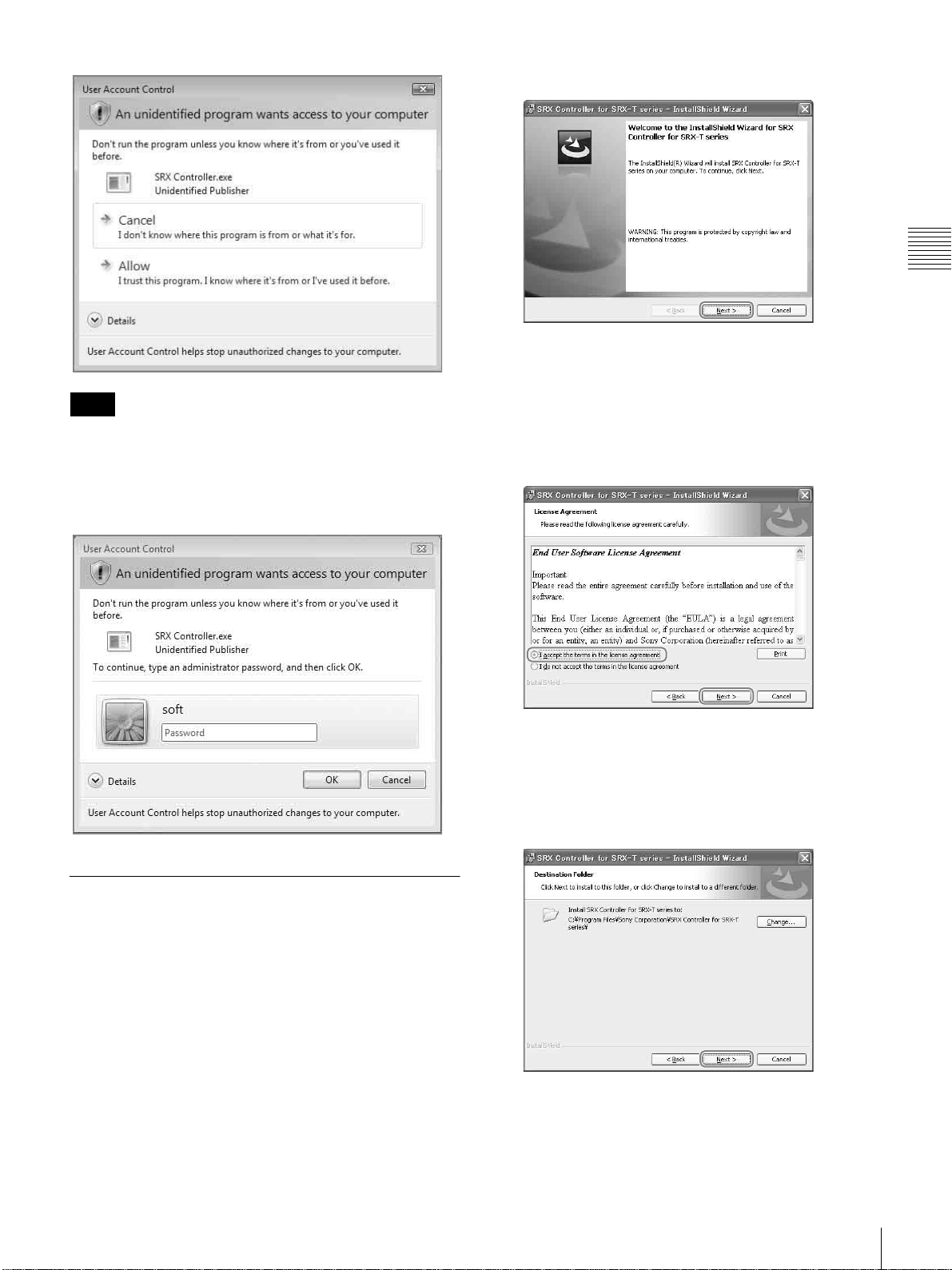
Note
2
Click [Next].
The software license agreement appears.
3
Read the agreement, select [I accept the terms in the
license agreement], and then click [Next].
Chapter 2 Preparations
If [Cancel] is selected, the application is not executed.
When the administrator password dialog is
displayed
Type an administrator password then click [OK].
If you select [I do not accept the terms in the license
agreement], the software will not be installed and the
wizard will close.
4
Select the destination folder for installation, and click
[Next].
To change the destination for installation, click
[Change] and specify the folder to which you want to
install.
Installing the SRX Controller
1
Start the installation wizard that was downloaded via
the installer.
Installing the SRX Controller in a Computer for Controlling the Projector
49
Page 50
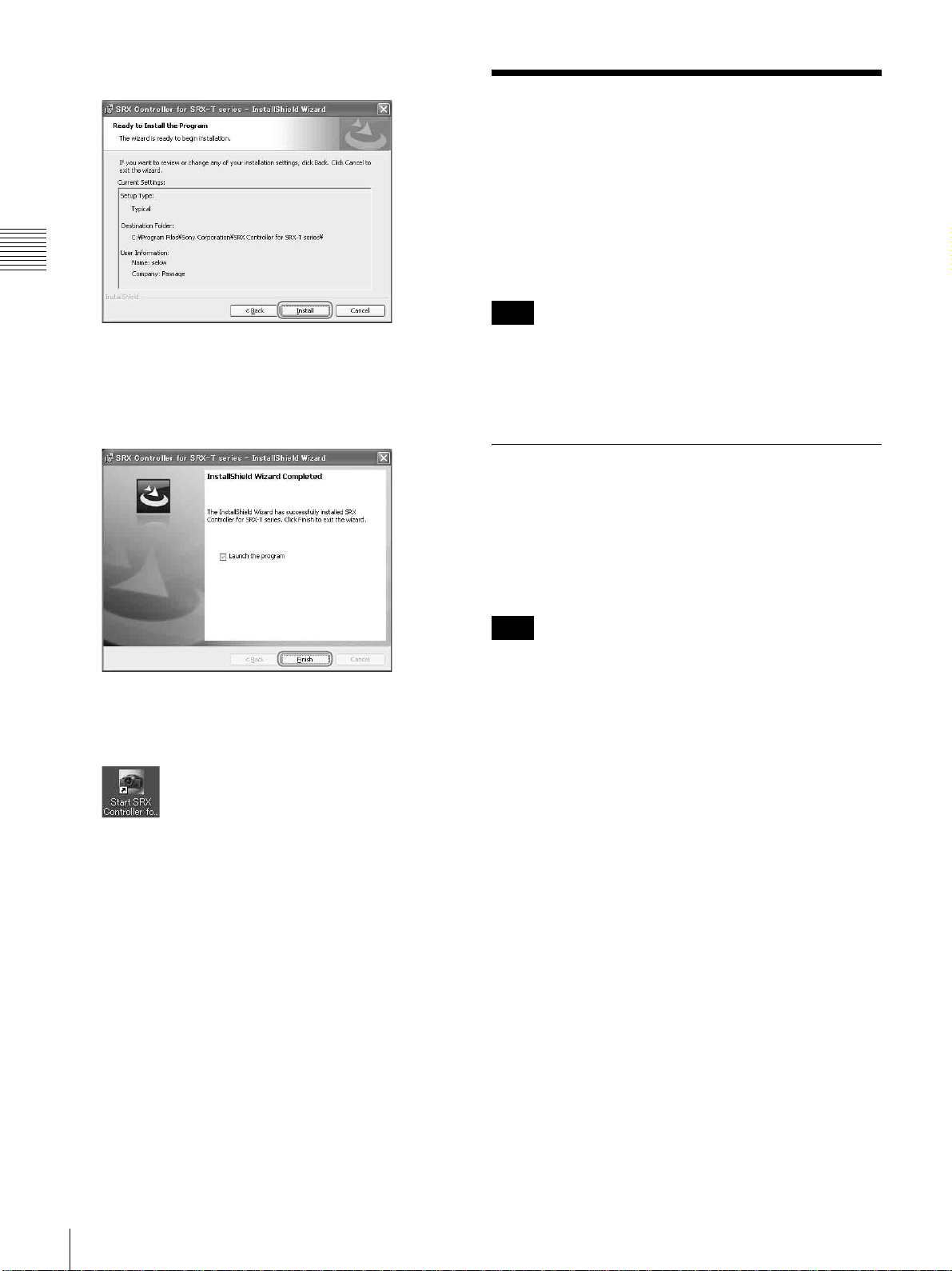
5
Click [Install].
Connecting a Computer
for Controlling the
Projector
Connect a computer for controlling the projector to the
projector via the ethernet cable or via the RS-232C
Chapter 2 Preparations
connector.
Note
Installation starts.
6
When the following screen appears, click [Finish].
If you selected the [Launch the program] checkbox,
SRX Controller will start immediately.
This completes installation of SRX Controller.
When SRX Controller is installed, the “Start SRX
Controller for SRX-T series” icon is created on your
desktop.
If both the NETWORK connector (LAN) and the RS-232C
connector (COM) are connected at the same time,
communication errors may occur. Use only one
connection at a time.
Connecting the Computer via the
Ethernet
Connect the computer to the ethernet cable (supplied)
connected to the projector inside.
For connecting the ethernet cable to the projector, consult
your dealer or your local Sony representative.
Note
Set the IP address of the connected computer to be
assingned from DHCP.
50
Connecting a Computer for Controlling the Projector
Page 51
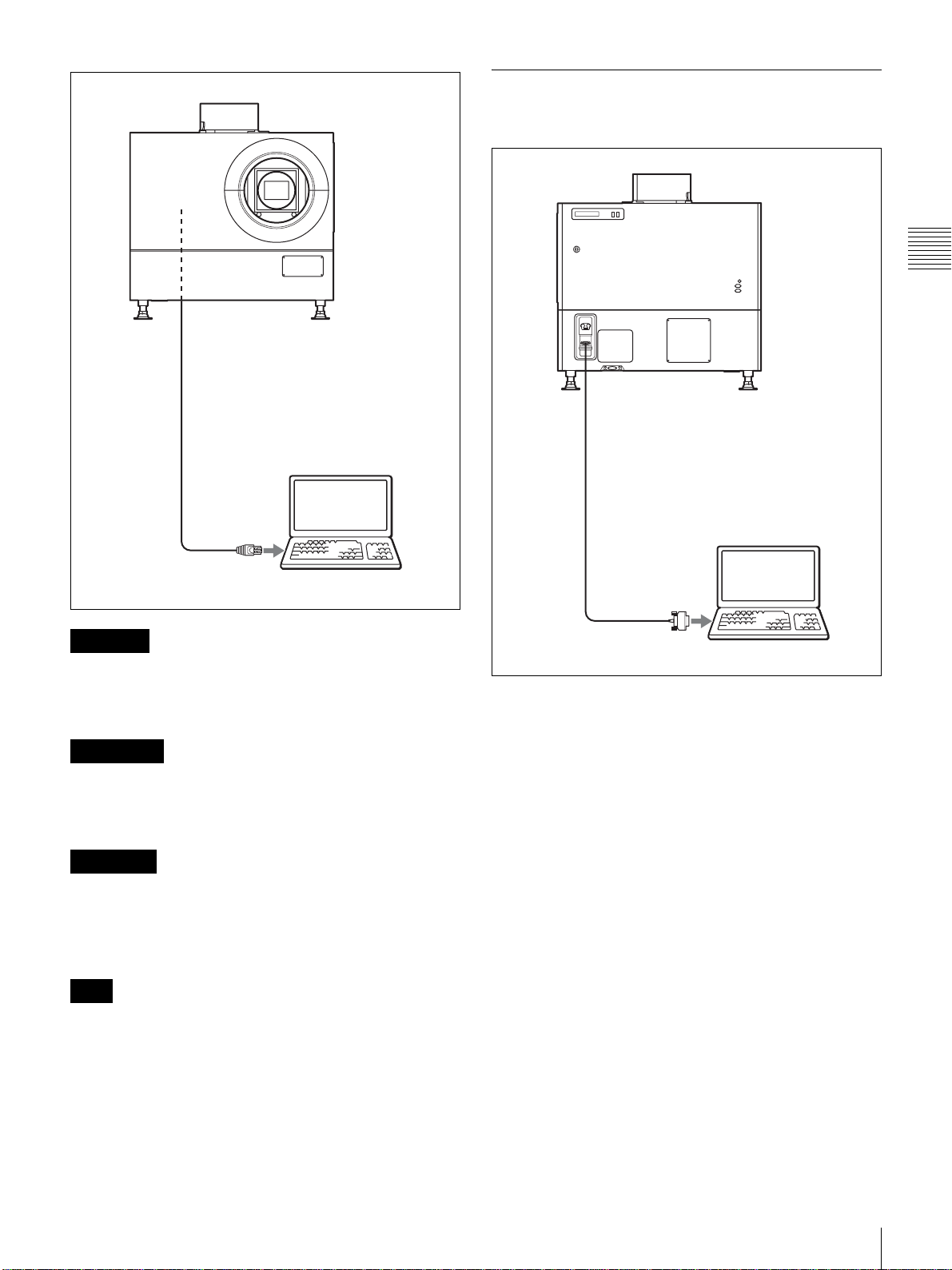
Connecting the Computer via the
RS-232C
Chapter 2 Preparations
Ethernet cable (cross cable)
(supplied)
Computer for controlling
the projector
Ethernet connector
CAUTION
For safety, do not connect the connector for peripheral
device wiring that might have excessive voltage to this
port. Follow the instructions for this port.
ATT ENT ION
Par mesure de sécurité, ne raccordez pas le connecteur
pour le câblage de périphériques pouvant avoir une tension
excessive à ce port. Suivez les instructions pour ce port.
RS-232C connector
Connecting cable (not supplied)
Computer for controlling
the projector
RS-232C connector
VORSICHT
Aus Sicherheitsgründen nicht mit einem PeripheriegerätAnschluss verbinden, der zu starke Spannung für diese
Buchse haben könnte. Folgen Sie den Anweisungen für
diese Buchse.
Note
If the power of the projector remains on for a long period
of time without the ethernet cable connected, the message
“Sony Data Projector Initializing…” may appear in the
STATUS MESSAGE window while you are setting up for
networking after connecting the ethernet cable. This is not
a malfunction of the projector.
Connecting a Computer for Controlling the Projector
51
Page 52
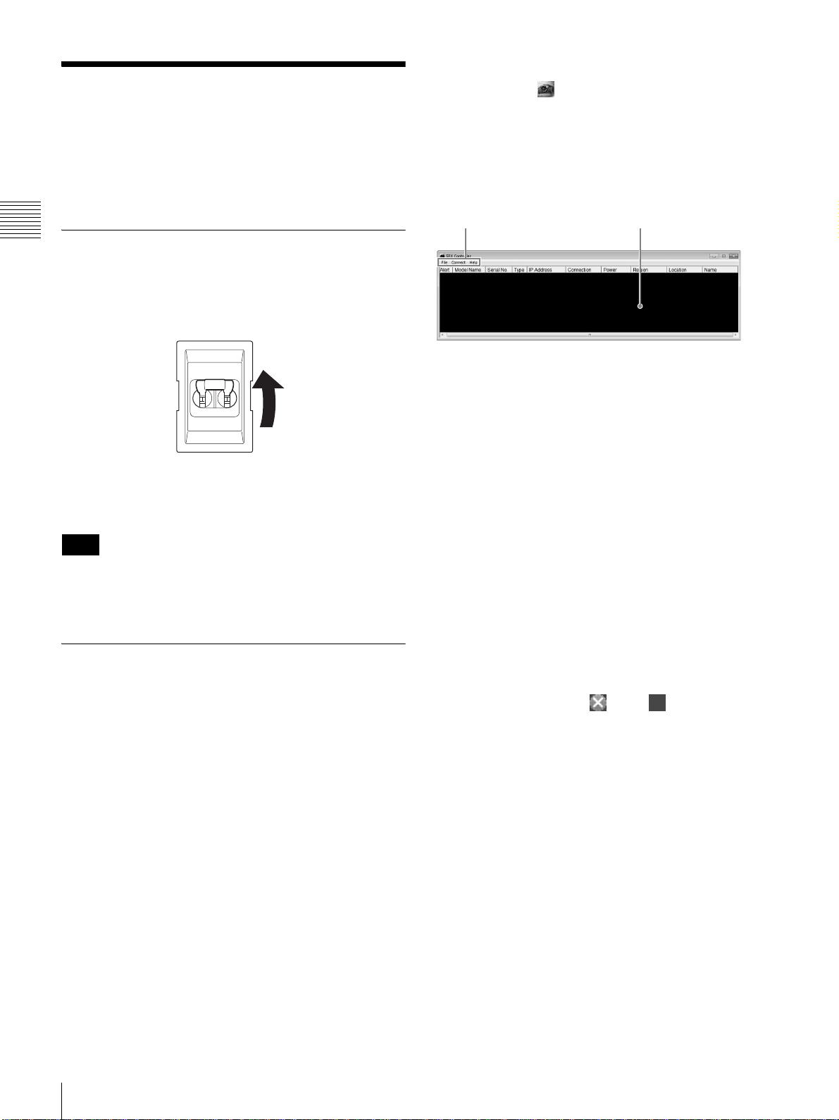
Starting the SRX
1 2
Controller
To start the SRX Controller
Double-click the icon for the SRX Controller in the
desktop window of the computer.
The SRX Controller starts and the Program Launcher
screen is displayed.
Turn on the projector’s main power, start SRX Controller,
and then start the projector.
Chapter 2 Preparations
Turning On the Main Power of the
Projector
Raise the power switch on the rear of the projector to the
on position (|) to turn on the projector.
The main power of the projector will turn on and enter the
standby mode, the MAIN indicator and LAMP indicator
will light red.
Note
Connect to SRX Controller after initialization of the
projector is complete and after the message in the message
display window disappears.
About the Program Launcher screen
12
a Menu bar
File
Select [Quit] from the [File] menu to exit the SRX
Controller.
Connect
Selects the connection mode between the projector and the
computer for controlling the projector.
For details, see “Changing the Connection Mode” on
page 53.
Help
Select [Version] from the [Help] menu to display the
version information of the SRX Controller.
Starting SRX Controller
Starting the software
If the controller PC has commercially available firewall
software installed, or the Windows firewall is enabled, the
firewall settings must be disabled.
When running Windows 7
Start [Windows Firewall], click [Allow a program or
feature through Windows Firewall], and select the
checkbox for SRX Controller in the list of allowed
programs and features. If SRX Controller does not appear
in the list, select [Change settings], and then add it by
clicking [Add another program].
For commercially available firewall software
Add “SRX Controller” to the Exceptions list, referring to
the operating instructions supplied with the software.
b Projector detect window
Information on all of the projectors connected to a network
is displayed.
Alert: Shows whether there is any warning information on
the projector or not. ( : Yes, : No)
Model Name: Model name of the projector
Serial No.: Serial number of the projector
Type: Protocol type (IPv6/IPv4) that can be used for
connection
IP Address: IP address of the projector
Connection: Network connection status of the projector
The projectors that can be selected with the SRX
Controller are indicated by [Connectable] under
[Connection].
Power: Power on/off status of the projector
Region: Region where the projector is installed
Location: Installation location of the projector
Name: Free name
To exit the SRX Controller
Click [Quit] from the [File] menu on the menu bar.
52
Starting the SRX Controller
Page 53

Changing the Connection Mode
When the projector you want to operate is connected to the
computer via a network, you can select it by specifying the
IP address of the projector. Connection via the RS-232C is
also available.
When connecting the computer via a network by
specifying the IP address of the projector
Select [Network] from the [Connect] menu on the menu
bar to open the dialog. Enter the IP address and model
name of the projector, then click [OK].
To change the port number, select [PC Port Setting] from
the [Connect] menu on the menu bar to display the dialog.
Enter the new port number in the dialog and click [OK].
When connecting the computer via RS-232C
Select [COM] from the [Connect] menu on the menu bar
to open the dialog. Enter the port number and model name
of the COM port (RS-232C) for the computer, then click
[OK].
Connecting the Projector
When you connect the projector, make sure to:
• Turn off all equipment before making any connections.
• Use the proper cables for each connection.
• Insert the cable plugs firmly; loose connections may
increase noise and reduce performance of picture
signals. When pulling out a cable, be sure to pull it out
from the plug, not the cable itself.
• When installing the optional input board, consult your
dealer or your local Sony representative.
• For connecting the cable to the connector inside the
projector, consult your dealer or your local Sony
representative.
Refer also to the instruction manuals of the equipment to
be connected.
Connecting a Computer Equipped
with a DVI-D Connector
Chapter 2 Preparations
Connect a computer with a DVI-D connector to the
optional LKRI-005 HDCP DVI input board installed to
any of INPUT A to INPUT D inside the projector.
Connecting the Projector
53
Page 54
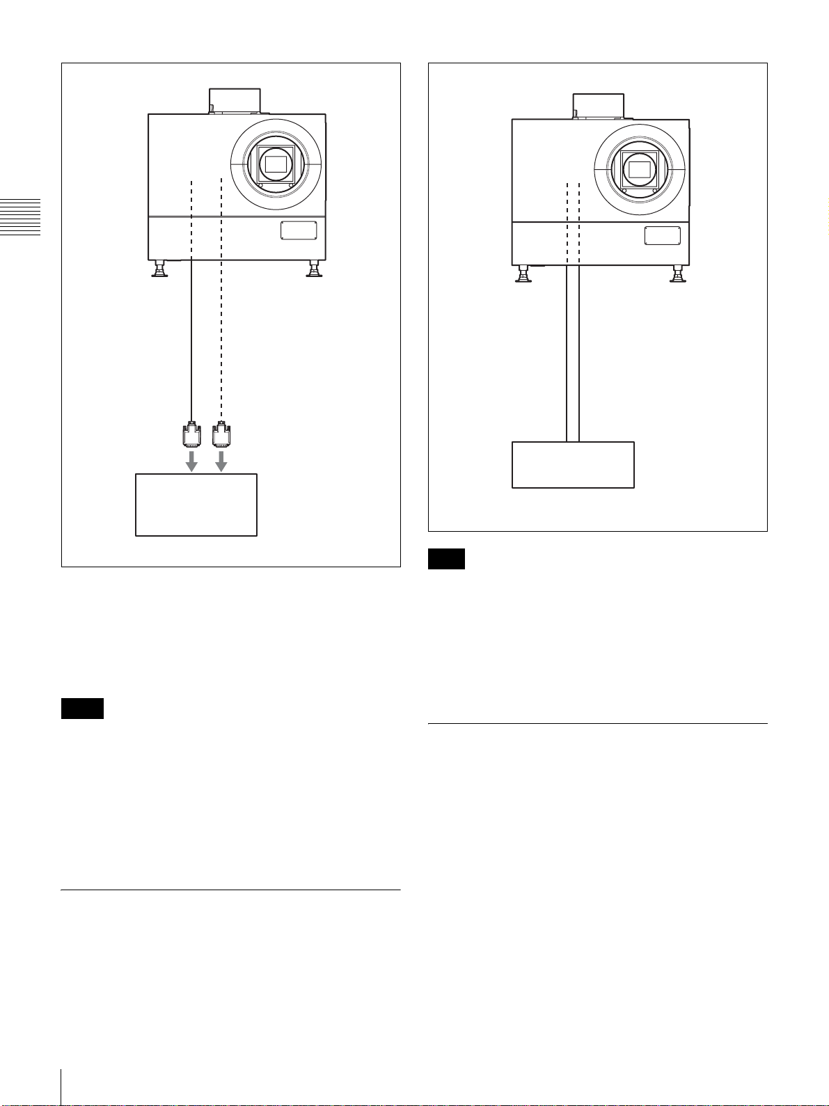
Chapter 2 Preparations
DVI cable
(not supplied)
DVI-D connector AUX connector
Computer
HDCP (High-bandwidth Digital Content Protection) DVID signal can also be input when the input signal with
specified resolution is input from LKRI-005.
For details, refer to the Operating Instructions of LKRI-
005.
Notes
• According to the input signal type, set [Signal Mode] on
[Input Source] in the PICTURE CONTROL window of
the SRX Controller. (page 59)
• When an extension cable is used, the signal may not be
input correctly due to signal reduction.
• If you input 10-bit signals from a DVI-D connector only
(10-bit single mode), a DVI cable compatible with the
Dual-link is required.
HD-SDI connecting cable
(not supplied)
to HD-SDI output
HD-SDI equipment, etc.
Note
When the LKRI-003 is attached to the projector, select the
type of signal with [Signal Mode] of [Input Source] in the
PICTURE CONTROL window. For Single-link input,
select [YPbPr] or [YPbPr FULL]. For Dual-link input,
select [RGB] or [RGB FULL].
For details, see page 59.
Connecting HDMI Equipment
You can connect HDMI equipment by installing an
optional LKRI-006 input board inside the projector. For
details, contact your dealer or your local Sony
representative.
Connecting HD-SDI Equipment
Install the optional LKRI-003 HD-SDI input board inside
the projector and connect HD-SDI equipment to the
connectors on the installed input board.
54
Connecting the Projector
Page 55
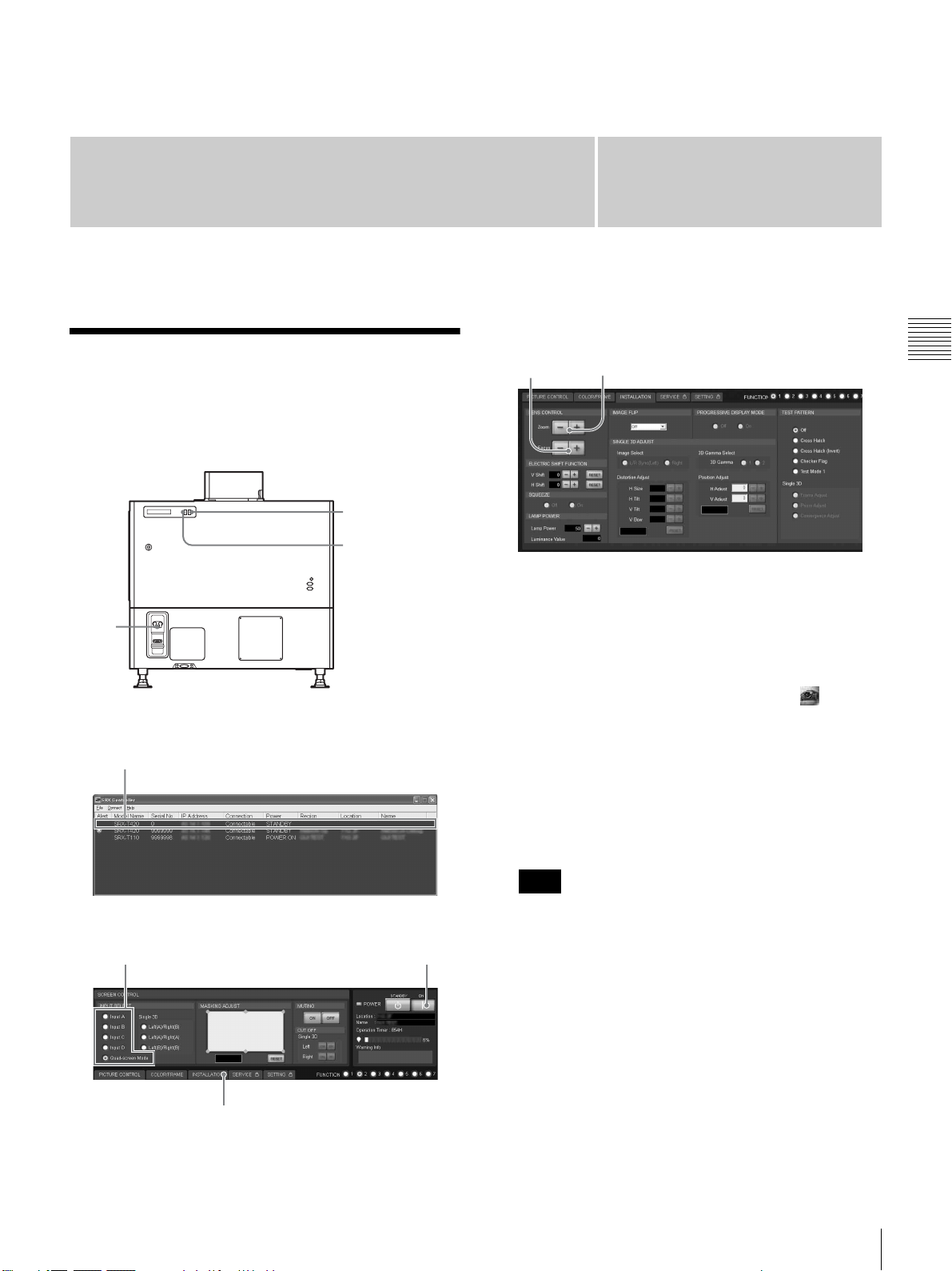
Projecting
Projecting the Picture
Use a computer in which the SRX Controller is installed to
project the picture on the screen.
LAMP indicator
MAIN indicator
1
Chapter
INSTALLATION window
3
8,10 9
1
Set the power switch on the rear of the projector to the
on position (:).
The MAIN and LAMP indicators light red and the
projector goes into standby mode.
Chapter 3 Projecting
Program Launcher screen
3
Control Function Menu window
6
7
4
2
Start your computer and double-click the icon of
the SRX Controller in the desktop window.
The Program Launcher screen appears.
3
Double-click the projector you want to operate.
The SRX Controller starts and the Control Function
Menu window appears.
Note
When you connect the projectors to the computer via a
network, you can also select the projector you want to
operate by specifying the IP address of the projector. If
connection is made via the RS-232C connector on the
projector, specify the RS-232C port number of the
computer.
For details, see “Changing the Connection Mode” on
page 53.
4
Click the [POWER ON ?] button to turn on the
projector.
The MAIN and LAMP indicators light green.
Projecting the Picture
55
Page 56
5
Turn on the equipment connected to the projector.
6
Select the input signal to be projected on the screen.
Click one of the INPUT SELECT radio buttons on the
SCREEN CONTROL window.
Input A: Selects the signal input from the connectors
on the preinstalled input board in the INPUT A
section.
Input B to Input D: Select the signal input from the
connectors on the optional input board in the
INPUT B to INPUT D sections, respectively.
Quad-screen Mode: Projects images in quad-screen
mode.
Images from four input signals are projected on
Chapter 3 Projecting
the screen simultaneously.
The image from signal input from INPUT A is
displayed on the upper left of the screen, that of
the signal from INPUT B on the upper right, that
of the signal from INPUT C on the lower left, and
that of the signal from INPUT D on the lower
right.
Note
Select the appropriate input signal from [Signal Mode]
of [Input Source] in the PICTURE CONTROL
window. Improper setting may cause deterioration of
the picture.
For details, see page 59.
To cut off the whole screen
Click the [ON] button of [MUTING]. The whole screen
appears in black. To restore the picture, click the [OFF]
button of [MUTING].
To turn off the power
1
Click the [POWER STANDBY 1] button, then the
[OK] button in the displayed confirmation dialog.
The MAIN and LAMP indicators flash green. The
projector detects the temperature of the lamp and the
fan continues to run for 3 to 15 minutes to reduce the
internal temperature. When the fan stops running, the
MAIN and LAMP indicators light red.
2
Set the power switch on the rear of the projector to the
off position (a).
Note
Do not switch the power switch to the lower (off)
position while the fan is running. Doing so stops the
fan before the temperature of the lamp has been cooled
down sufficiently and may damage the unit.
Projecting a 4K Signal in QuadScreen Mode
Notes when quad-screen mode is selected in
step 6
• When projecting moving pictures in quad-screen
mode, all the input signals should be genlocked to
synchronize with each other with a phase difference
of less than 5 µsec. The projected moving picture not
synchronized with the reference picture will appear
to have dropped frames. A moving picture on the
upper left screen for quad-screen mode is regarded
as a reference picture. If you project still pictures and
moving pictures together, select the upper left screen
for the moving picture.
• When projecting signals with vertical frequency of
more than 1080 pixels such as UXGA and WUXGA,
a part of the displayed image may be invisible.
7
Click the [INSTALLATION] button.
The INSTALLATION window appears.
8
Adjust the focus with the [Focus +/–] buttons under
[LENS CONTROL].
9
Adjust the picture size with the [Zoom +/–] buttons.
4K signals separately input from four input boards can be
projected as one 4K image in quad-screen mode.
When projecting a 4K image, all the input signals should
be genlocked to synchronize with each other with a phase
difference of less than 5 µsec. Set [Signal Mode] and [I/P
Mode] of [Input Source] in the PICTURE CONTROL
window to the same settings for INPUT A to INPUT D.
After completing the above, click the [On] radio button
with [PROGRESSIVE DISPLAY MODE] in the
INSTALLATION window.
Notes
• [PROGRESSIVE DISPLAY MODE] is effective when
the signals below are input in the same refresh rate.
- Four 1920 × 1080 signals
- Four 2048 × 1080 signals
- Four SXGA+ (1400 × 1050) signals
[PROGRESSIVE DISPLAY MODE] cannot be selected
for any other signals that are not stated above.
• Depending on signal types, there are certain limits when
displaying the signal. To check whether the signal can be
projected as 4K images, see the following table.
56
10
Adjust the focus again with the [Focus +/–] buttons.
Projecting the Picture
Page 57
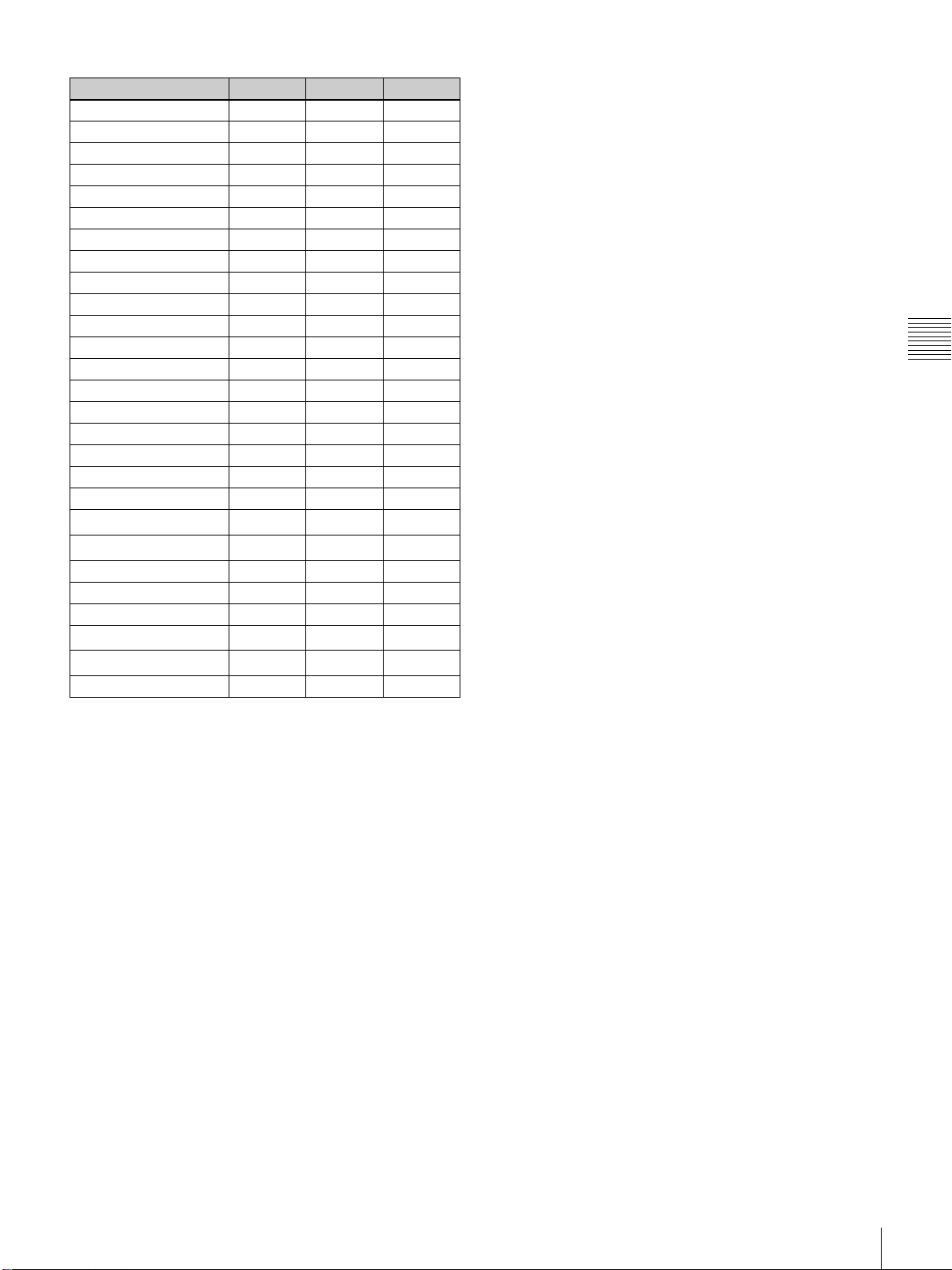
Type of signal LKRI-003 LKRI-005 LKRI-006
1080_60i v – v
1024×768_VESA60 – zz
1024×768_VESA70 – – –
1024×768_VESA75 – – –
1024×768_VESA85 – – –
1280×960_VESA60 – zz
1280×1024_VESA60 – zz
1280×1024_VESA75 – – –
1280×1024_VESA85 – – –
1600×1200_VESA60 – × ×
1080_50i v – v
720_60P zzz
720_50P zzz
1080_24PsF a ––
1400×1050_VESA60 – aa
2048×1080_48i v ––
2048×1080_50i v ––
2048×1080_60i v ––
1080_24P aaa
1080_50P
1080_60P
a
a
1)
1)
aa
aa
2048×1080_24P aaa
2048×1080_25P a ––
2048×1080_30P a ––
2048×1080_48P
2048×1080_60P
a
a
1)
1)
a –
aa
1920×1200_DVI_60 – × ×
a: Both still pictures and moving pictures can be projected as 4K
images.
z:Both still pictures and moving pictures are projected with a line
in the center.
v: Only moving pictures are projected with a line in the center.
×: The picture cannot be projected as 4K images, because the lower
portion of the pictures is cut off.
–: Both still pictures and moving pictures cannot be projected as 4K
images.
Chapter 3 Projecting
1) Vertical lines may appear in the center of the screen when a 4:4:4 ⇒ 4:2:2
conversion filter is applied to the sent signal. Use a signal that does not
have a filter applied.
Projecting the Picture
57
Page 58
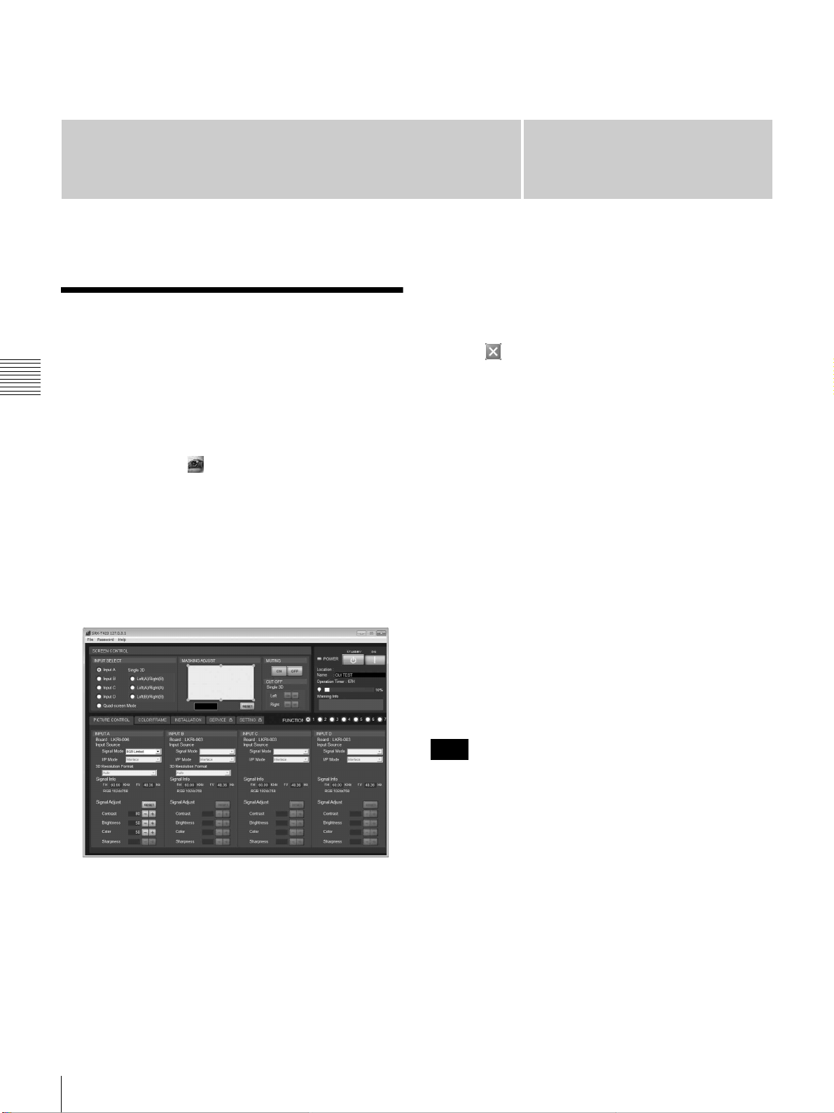
Adjustments and Settings
Using the SRX Controller
Displaying the Control
Function Menu Window
Chapter 4 Adjustments and Settings Using the SRX Controller
When you install the SRX Controller in a computer, you
can operate the picture adjustments, input signal settings,
installation settings, etc. from the computer.
1
Double-click the icon of the SRX Controller in the
desktop window of the computer.
The Program Launcher screen appears.
2
Select the projector you want to operate by doubleclicking the projector.
The SRX Controller starts and the Control Function
Menu window appears.
Chapter
To clear the Control Function Menu
window
Select [Quit] from the [File] menu on the menu bar, or
click the (close) button.
To reset the settings that have been
adjusted
Clicking the [RESET] button in the PICTURE CONTROL
window resets all the settings of adjustable items for
[Signal Adjust] to their factory preset values. To reset the
settings of the items for [Frame Adjust] in the COLOR/
FRAME window, click the [RESET] button in the
COLOR/FRAME window.
To register the settings that have been
adjusted
You can register the settings that have been adjusted in the
control windows to FUNCTION 1 to 7. As the default
setting, the settings are registered to FUNCTION 1. To
register the settings to FUNCTION 2 to 7, click one of the
FUNCTION 2 to 7 radio buttons, then adjust the items in
each window.
You can recall it later to project the picture with the desired
setting by clicking one of the FUNCTION radio buttons.
4
58
3
Click any of the [PICTURE CONTROL], [COLOR/
FRAME] and [INSTALLATION] buttons to display
the desired control window.
For details, see “PICTURE CONTROL Window” on
page 59, “COLOR/FRAME Window” on page 60 and
“INSTALLATION Window” on page 62.
Displaying the Control Function Menu Window
Note
When you click the FUNCTION button to switch to
another FUNCTION setting, the picture will be cut off for
up to about 10 seconds. The picture with the selected
FUNCTION setting will then appear on the screen.
About the items that cannot be adjusted
Items that cannot be adjusted depending on the input signal
are not displayed in the window.
For details, see “Input Signals And Adjustable/Setting
Items” on page 63.
Page 59
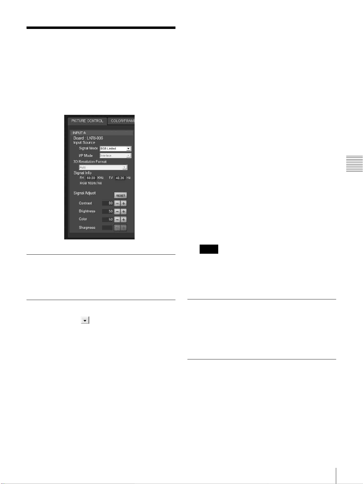
PICTURE CONTROL
Window
The PICTURE CONTROL window is used to select the
input source or to adjust the picture quality.
When [Quad-screen Mode] is selected with the INPUT
SELECT radio buttons, the items can be independently
adjusted for each input channel displayed on the screen.
When the LKRI-003 is installed
For Single-link input, select [YPbPr] or [YPbPr
FULL].
For Dual-link input, select [RGB] or [RGB FULL].
When [RGB] or [YPbPr] is selected, in the case that a
10-bit HD-SDI signal is input and [Contrast] is set to
90 in [Signal Adjust] of the PICTURE CONTROL
window, mapping is done so that HD-SDI signal data
values
of 0 to 100% to display an image on the projector.
When [RGB FULL] or [YPbPr FULL] is selected, in
the case that a 10-bit HD-SDI signal is input and
[Contrast] is set to 90 in [Signal Adjust] of the
PICTURE CONTROL window, mapping is done so
that HD-SDI signal data values of 0 to 1023 are
converted to the video levels of 0 to 100% to display
an image on the projector. In this case, inhibition
codes included in a 10-bit HD-SDI signal (data area 0
to 3, and 1020 to 1023) are blocked out.
1)
When the LKRI-006 is installed
Selects based on the input signal.
1)
of 64 to 960 are converted to the video levels
Data value 64 of a 10-bit HD-SDI signal input is
equivalent to the video level of 0% (black), and data value
960 equivalent to 100% (white).
Chapter 4 Adjustments and Settings Using the SRX Controller
Board
Shows the input board installed in the relative input board
slot of the projector.
Input Source
Signal Mode: Click to open the drop-down list to
select the type of signal input from equipment
connected to the optional input board.
When the LKRI-005 is installed
Select the input signal type of progressive DVI-D
signals.
When used in normal, select [8bit Single Full], which
is compatible with DVI1.0 standard and the signal
level is Full Range compliance.
When the DTV signal is input, select [8bit Single
Limited], which is compatible with DVI1.0 standard
and the signal level is Limited Range compliance.
When the 10-bit signal based on Sony’s unique
specification is input, select [10bit Twin Full] or
[10bit Single Full] for a signal of Full Range
compliance, or [10bit Twin Limited] or [10bit Single
Limited] for a signal of Limited Range compliance.
I/P Mode: Selects the I/P conversion mode. Depending on
the input signal source, set the mode to [Interlace],
[PsF] or [1080 50p60p].
Notes
• This item is available with the interlace, PsF or HD
50P/60P signal input.
• When the LKRI-005 is installed, this item is not
available.
3D Resolution Format
If [Single 3D] is selected with the INPUT SELECT radio
buttons, select [Auto] under normal circumstances.
If the projected image is abnormal, select according to the
input data.
Signal Info (Information)
Shows the horizontal and vertical frequencies of the input
signal automatically. The values are approximate.
The type of the input signal is also displayed.
fH: Displays the horizontal frequency.
fV: Displays the vertical frequency.
PICTURE CONTROL Window
59
Page 60
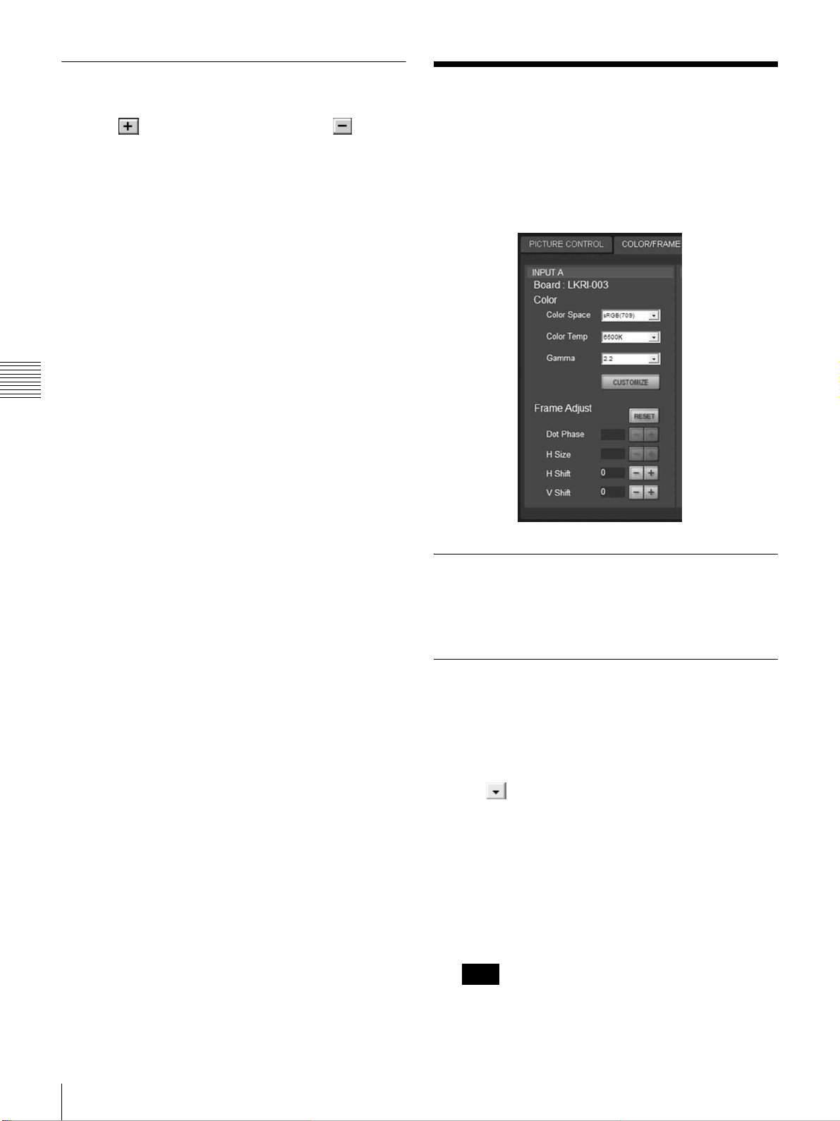
Signal Adjust
Adjusts the picture quality of the input signal.
Clicking increases the setting value, and
decreases it.
Clicking the [RESET] button resets the following four
settings to the factory preset values.
Contrast: Adjusts the picture contrast. The higher the
setting, the greater the contrast.
Brightness: Adjusts the picture brightness. The higher the
setting, the brighter the picture.
Color: Adjusts the color intensity. The higher the setting,
the greater the intensity.
Sharpness: Adjusts the picture sharpness. The higher the
setting, the sharper the picture. The lower the setting,
the softer the picture.
Chapter 4 Adjustments and Settings Using the SRX Controller
COLOR/FRAME Window
The COLOR/FRAME window is used to adjust the input
signal.
When [Quad-screen Mode] is selected with the INPUT
SELECT radio buttons, the items can be independently
adjusted for each input channel displayed on the screen.
Board
Shows the input board installed in the relative input board
slot of the projector.
Color
Adjusts the items so that you can obtain precise color
reproduction.
If the color of an image is not correct, check the setting of
[Color Space] first.
Select the setting from the drop-down list displayed by
clicking .
Color Space: Selects the color gamut.
sRGB(709): Select when projecting a normal high-
definition signal or RGB signal.
DCDM: Select when projecting a signal source using
the Minimum D-Cinema Color Gamut defined by the
DCI Specifications Book/Version 1.0.
CIE XYZ: Select when projecting an XYZ signal
from LKRI-003.
Note
60
Set [Signal Mode] of [Input Source] in the PICTURE
CONTROL window to [RGB FULL].
COLOR/FRAME Window
Page 61
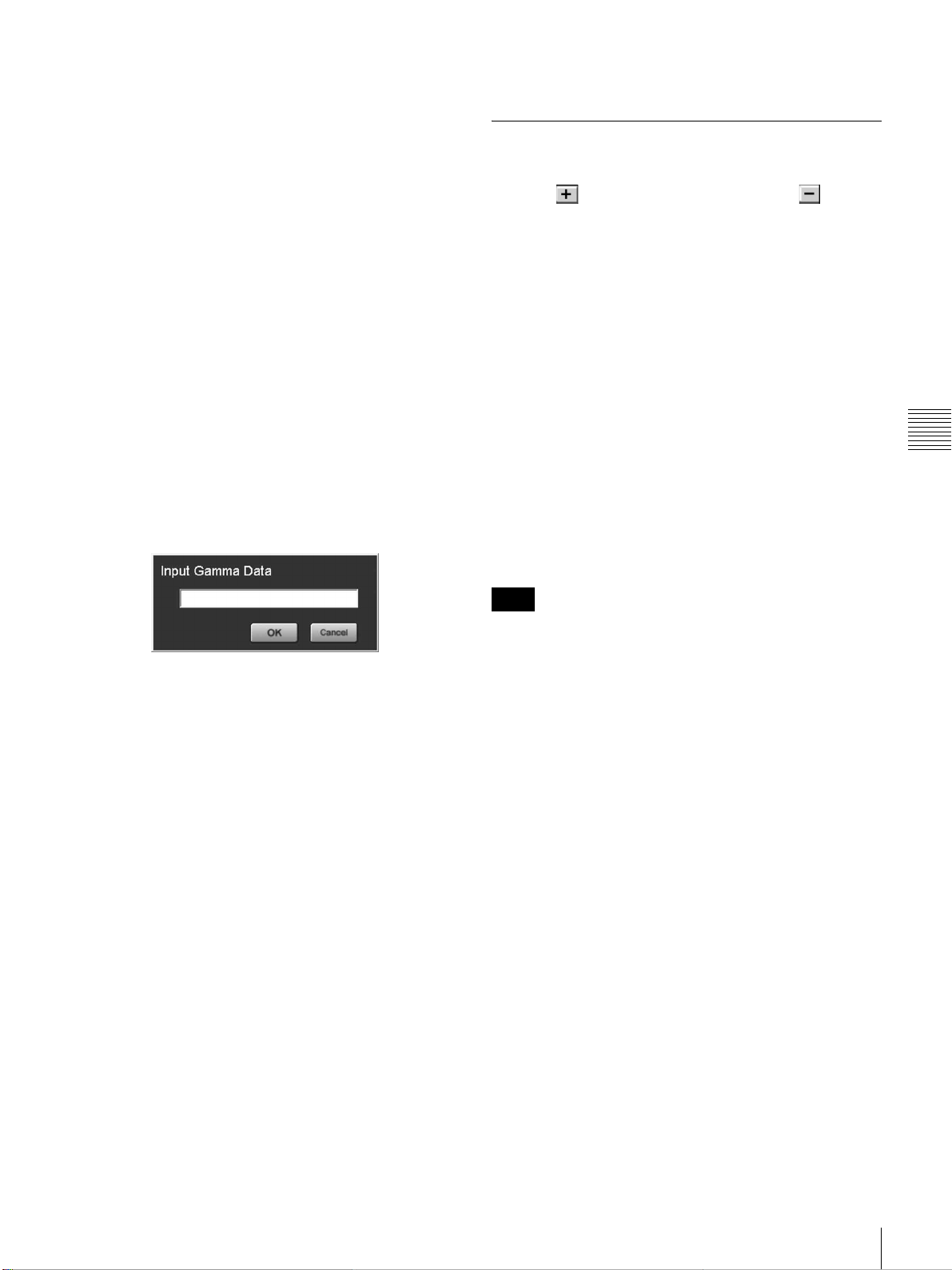
Adobe RGB: Select when projecting Adobe RGB
compatible computer signals.
CUSTOM: Select when projecting a signal using the
color gamut defined by the user. The default value is
the same as DCDM.
Color Temp (temperature): Selects the color
temperature from among [DCI W/P], [6500K],
[9300K], [CUSTOM1], [CUSTOM2] and
[CUSTOM3]. 6500K is preset in CUSTOM1 to 3
settings in the factory.
[6500K] is recommended for a normal high-definition
signal or RGB signal. Set this item to [DCI W/P] to
project a movie source.
Gamma: Selects a gamma correction curve. The smaller
the value, the brighter the image. [2.2] is
recommended to project a normal high-definition
signal or RGB signal.
Select [2.6] or [2.2], or set a value from 1.80 to 2.59
(except 2.20) in 0.01 steps according to the signal
input. This allows projection of an image with
optimum brightness.
To set the gamma value in 0.01 steps, set [Gamma] to
[1.8], and click the [CUSTOMIZE] button. Input the
values in the Input Gamma Data screen and press the
[OK] button.
CUSTOMIZE: Value set using CUSTOMIZE
Frame Adjust
Adjusts the horizontal size and the position of the picture.
Clicking increases the setting value, and
decreases it.
Clicking the [RESET] button resets all the settings of
[Frame Adjust] to the factory-preset values.
Dot Phase: Adjusts the phase of the SXRD panels and the
input signal. Adjust the value to obtain the clearest
picture. The item does not function with this
projector.
H Size: Adjusts the horizontal size of the picture according
to the input signal. As the setting value increases, the
horizontal size of the picture becomes larger. The
item does not function with this projector.
H Shift: Adjusts the horizontal position of the picture. As
the setting value increases, the picture moves to the
right. As the value decreases, the picture moves to the
left.
V Shift: Adjusts the vertical position of the picture. As the
setting value increases, the picture moves up. As the
value decreases, the picture moves down.
Chapter 4 Adjustments and Settings Using the SRX Controller
When a signal is input from the connector
on the LKRI-005
When you set each item in [Color], the setting will be
written to the color space description area of the EDID
ROM.
The values to be written to the EDID ROM are shown
below.
Color Space settings
sRGB(709): Red (0.6400, 0.3300), Green (0.3000,
0.6000), Blue (0.1500, 0.0600)
Adobe RGB: Red (0.6400, 0.3300), Green (0.2100,
0.7100), Blue (0.1500, 0.0600)
DCDM, CIE XYZ, CUSTOM: Red (0.6800,
0.3200), Green (0.2650, 0.6900), Blue (0.1500,
0.0600)
Color Temp settings
6500K: White (0.3127, 0.3290)
9300K: White (0.2840, 0.2970)
DCI W/P: White (0.3140, 0.3510)
CUSTOM1 to CUSTOM3: White (0.3127, 0.3290)
(default values)
Gamma settings
2.6: 2.6
2.2: 2.2
Note
If the position of the picture is not adjusted correctly, noise
may appear in the blank portion of the screen. This is not a
malfunction of the projector. Adjust the picture position
correctly with [Frame Adjust].
COLOR/FRAME Window
61
Page 62
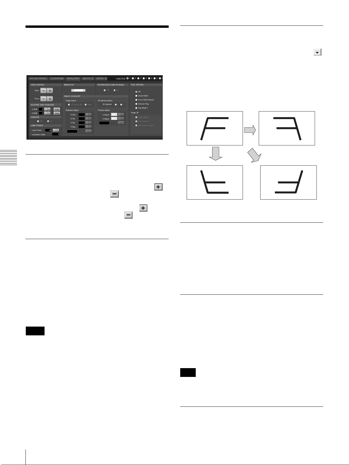
INSTALLATION Window
The INSTALLATION window is used to adjust the
projected picture and to change the lamp output, etc.
LENS CONTROL
Chapter 4 Adjustments and Settings Using the SRX Controller
Adjusts the projected picture on the screen.
Zoom +/–: Adjusts the size of the picture. Clicking
enlarges the picture size, and reduces the picture
size.
Focus +/–: Adjusts the picture focus. Clicking focuses
on a picture further back. Clicking focuses on a
forward picture.
IMAGE FLIP
Flips the picture.
Select it from the drop-down list displayed by clicking
according to the installed condition of the projector.
Off: Normal projection
H: Flips the picture horizontally
V: Flips the picture vertically
HV: Flips the picture horizontally and vertically
Off H
V HV
PROGRESSIVE DISPLAY MODE
ELECTRIC SHIFT FUNCTION
Adjusts the position of the projected pictures electrically.
V Shift: Adjusts the vertical position of the image.
Increase the value to move the image up, and decrease
the value to move it to down.
H Shift: Adjusts the horizontal position of the image.
Increase the value to move the image to the right, and
decrease the value to move it to the left.
RESET: Restores each setting to its default value.
Notes
• This function is effective in the following cases:
- When single-screen mode is selected
- When quad-screen mode is selected and
[PROGRESSIVE DISPLAY MODE] is set to [On]
• When this function is used for quad-screen mode, all the
projected signals should be genlocked to synchronize
with each other with a phase difference of less than 5
µsec. If they are not synchronized, the picture is not
displayed correctly.
Normally, click the [Off] radio button.
Click the [On] radio button when the signals from four
input boards are used to project a 2048 (1920) × 1080-pixel
signal as a 4096 (3840) × 2160-pixel 4K image or to
project a 1400 × 1050-pixel (SXGA+) signal as a 2800 ×
2100-pixel image in single-screen mode.
SQUEEZE
This function allows the input signal to be displayed on the
screen in a converted aspect ratio.
When you click the [On] radio button, the 720p, 1920 ×
1080 or 2048 × 1080 signal with a 16:9 aspect ratio can be
displayed by stretching to a 2.39:1 aspect ratio.
When you click the [Off] radio button, the input signal is
displayed without converting the aspect ratio.
Note
This function is available only for projection in singlescreen mode.
62
LAMP POWER
Adjusts the lamp power output.
INSTALLATION Window
Page 63
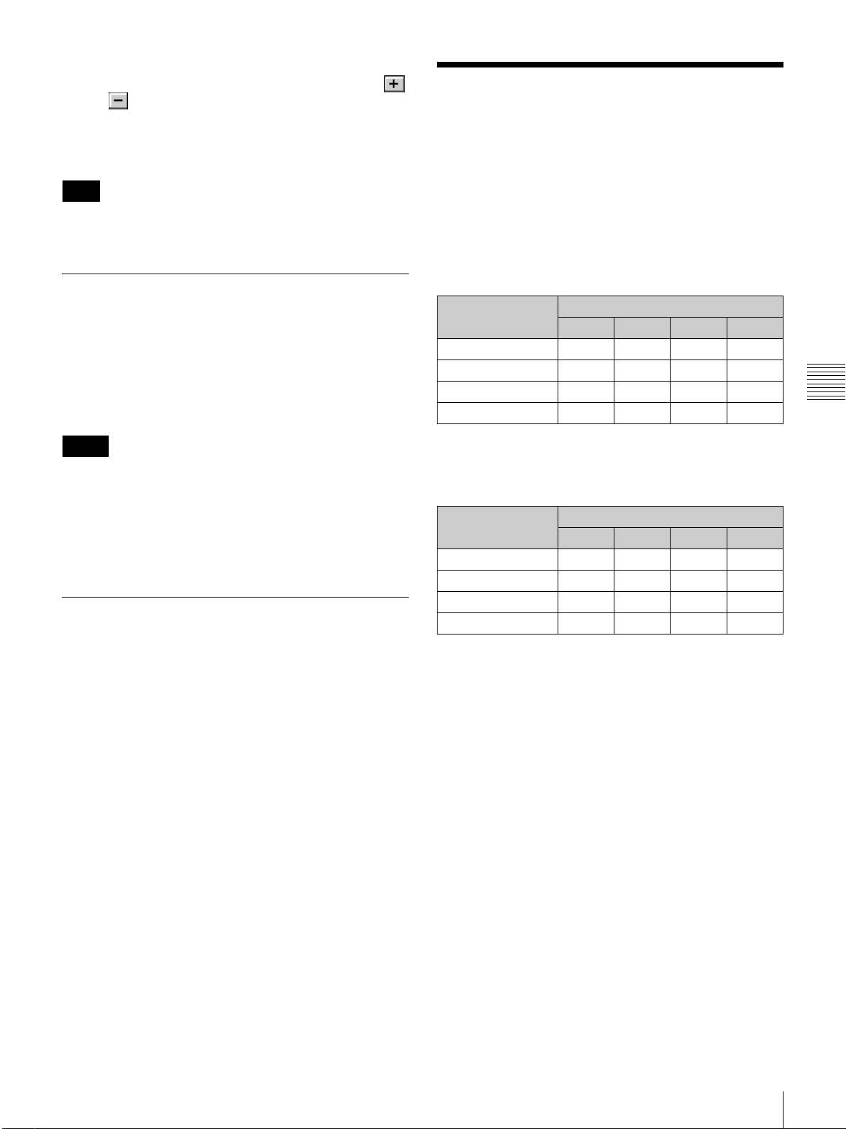
Lamp Power: You can reduce the lamp power to a value
from 50% to 100% in increments of 1% using the
or button.
Luminance Value: The value is referred to when your
Sony service representative performs axis
adjustments after replacing the lamp.
Note
Switching the lamp output frequently may reduce the lamp
life. Use of the defined lamp output is recommended.
TEST PATTERN
Displays a built-in test pattern on the screen for adjusting
the picture with no signal input from external equipment.
Click the radio button of the desired test pattern from
among [Cross Hatch], [Cross Hatch (Invert)], [Checker
Flag] and [Test mode 1 (all white)]. When you do not
display a built-in test pattern, click the [Off] radio button.
Input Signals And
Adjustable/Setting Items
Some items of [Signal Adjust] in the PICTURE
CONTROL window and [Frame Adjust] in the COLOR/
FRAME window are not adjusted or set depending on the
input signals. Items that cannot be adjusted depending on
the input signal are not displayed in the window.
Signal Adjust
Item
Contrast zzzz
Brightness zzzz
Color z – z –
Sharpness z –––
HD-SDI DVI-D HDMI 4K
Input signal
Chapter 4 Adjustments and Settings Using the SRX Controller
Notes
• While a built-in test pattern is displayed on the screen,
you cannot switch the INPUT SELECT radio button,
and cannot adjust the PICTURE CONTROL.
• [Single 3D] is used for projecting a 3D image. For
details, contact your dealer or your local Sony
representative.
SINGLE 3D ADJUST
Used to project a 3D image.
For details, contact your dealer or your local Sony
representative.
z: Adjustable/can be set
–: Not adjustable/cannot be set
Frame Adjust
Item
Dot Phase ––––
H Size ––––
H Shift zz––
V Shift zz ––
z: Adjustable/can be set
–: Not adjustable/cannot be set
HD-SDI DVI-D HDMI 4K
Input signal
Input Signals And Adjustable/Setting Items
63
Page 64
Others
Chapter
5
Recommended
Replacement Time
Recommended usage time of the projection lamp is
approximately 600 hours.
The bar of the indicator in the Control Function Menu
window becomes red when the time for replacement is
coming near. The percentage indicates the time used
Chapter 5 Others
before the recommended time for replacement. Use them
as a guide.
Be sure to ask your dealer or your local Sony
representative to replace a projection lamp.
Maintenance
Some components of the projector are consumable parts
over a long period of use.
To keep the projector working properly and to prolong its
usable lifetime, have the projector inspected periodically.
We recommend you make a maintenance contract for
periodical inspection with us. For details on the contract,
consult with your dealer or your local Sony representative.
64
Recommended Replacement Time / Maintenance
Page 65
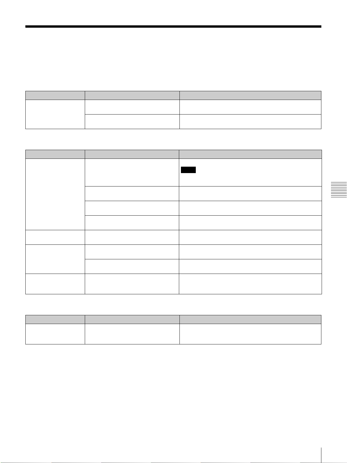
Troubleshooting
If the projector appears to be operating erratically, try to diagnose and correct the problem using the following guide. If
the problem still persists, consult your dealer or your local Sony representative.
Power
Symptom Cause Remedy
Power is not turned on. The main power is turned off. Set the power switch on the rear of the projector to the on position
The projector and a computer for
controlling the projector are disconnected.
Picture
Symptom Cause Remedy
No picture. Cables are disconnected. Check that the proper connection has been made (page 53).
Input selection is not correct. Check that the INPUT SELECT radio button in the SCREEN
The picture is cut off. Click the [OFF] button of [MUTING] in the SCREEN CONTROL
Ambient temperature is high. Reduce the room temperature so that it becomes within the
Color balance is incorrect. Incorrect input source mode is selected. Set [Signal Mode] of [Input Source] in the PICTURE CONTROL
The picture is too dark. Contrast and brightness has not been
A line appears in the
center of a projected 4K
image.
adjusted properly.
Lamp power output is not properly
selected.
The input signal is not suitable to be
projected as a 4K image.
(:) (page 55).
Connect the projector and a computer properly (page 50).
Note
For connections to the projector, contact your dealer or your local
Sony representative.
CONTROL window is selected correctly (page 56).
window (page 56).
operating temperature (5°C to 35°C).
window correctly (page 59).
Adjust the [Contrast] or [Brightness] in the PICTURE CONTROL
window (page 60).
Set [LAMP POWER] in the INSTALLATION window correctly
(page 62).
Check that the signal can be projected as a 4K image (page 57).
Chapter 5 Others
SRX Controller
Symptom Cause Remedy
The “Control Function
Menu” window does not
appear.
The projector and a computer for
controlling the projector are disconnected.
Check that the proper connection between the projector and a
computer has been made (page 50).
Troubleshooting
65
Page 66
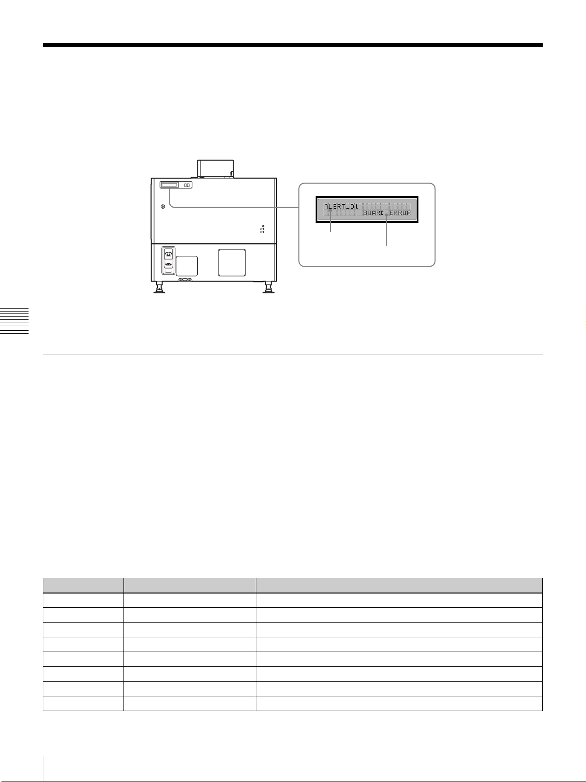
Messages
The messages are displayed in the STATUS MESSAGE window at the rear of the projector.
Displayed messages are classified into “Error messages” and “Information messages.”
The error messages are also displayed under “Warning Info” in the “Control Function Menu” window of the SRX
Controller.
Rear of the projector
STATUS MESSAGE window
Message number
Message
Chapter 5 Others
Error Messages
Error messages are classified into three types, described below, depending on the danger level.
If an error occurs, the message number and the message are displayed in the STATUS MESSAGE window.
ALERT: Danger level - High
Message number: ALERT_xx
WARNING: Danger level - Middle
Message number: WARN_xx
FAILURE: Danger level - Low
Message number: FAIL_xx
If an error message is displayed, contact your dealer or your local Sony representative and give them the message and its
number.
ALERT: Danger level - High
Message number Error message Meaning
ALERT_01 BOARD ERROR Trouble with power of IFA board
ALERT_02 BOARD ERROR Trouble with power of IFB board
ALERT_03 BOARD ERROR Trouble with power of IFC board
ALERT_04 BOARD ERROR Trouble with power of IFD board
ALERT_05 BOARD ERROR Trouble with power of MX board
ALERT_06 BOARD ERROR Trouble with power of LPD board
ALERT_07 BOARD ERROR Trouble with power of CT board
ALERT_08 BOARD ERROR Trouble with power of DST board
66
Messages
Page 67
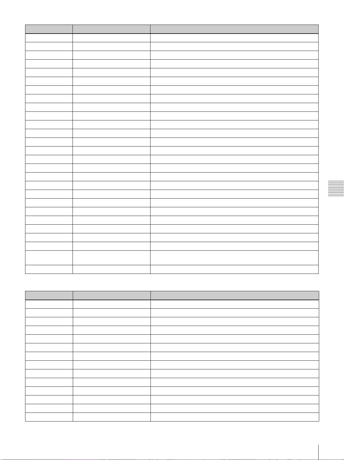
Message number Error message Meaning
ALERT_09 BOARD ERROR Trouble with power of PR1 board
ALERT_10 BOARD ERROR Trouble with power of PR2 board
ALERT_11 BOARD ERROR Trouble with power of SY board
ALERT_12 BOARD DETACHED CN board disconnected
ALERT_13 BOARD DETACHED MX board disconnected
ALERT_14 BOARD DETACHED LPD board disconnected
ALERT_15 BOARD DETACHED CT board disconnected
ALERT_16 BOARD DETACHED DST board disconnected
ALERT_17 BOARD DETACHED PR1 board disconnected
ALERT_18 BOARD DETACHED PR2 board disconnected
ALERT_19 TEMPERATURE ERROR Temperature of R panel is too high, and the unit stops operation.
ALERT_20 TEMPERATURE ERROR Temperature of G panel is too high, and the unit stops operation.
ALERT_21 TEMPERATURE ERROR Temperature of B panel is too high, and the unit stops operation.
ALERT_22 COVER DETACHED Rear cover detached and/or internal mirror position changed
ALERT_27 FAN ERROR Abnormal in fan A for lamp
ALERT_28 FAN ERROR Abnormal in fan B for lamp
ALERT_29 FAN ERROR Abnormal in fan C for lamp
ALERT_30 FAN ERROR Abnormal in fan D for lamp
ALERT_32 BALLAST ERROR Temperature of lamp power is too high, and the unit stops operation.
ALERT_33 BALLAST ERROR Abnormal in the fans for lamp power
ALERT_34 BALLAST ERROR Abnormal in the lamp power
ALERT_35 LAMP ERROR The lamp does not light, or goes out.
ALERT_36 BALLAST ERROR Abnormal in the lamp power
ALERT_37 COVER DETACHED Abnormal position of the lamp house cover
ALERT_38 BOARD ERROR Trouble with power of CN board
ALERT_39 TEMPERATURE ERROR Temperature of 8-inch duct attachment part is too high, and the unit stops
operation.
ALERT_41 COVER DETACHED Filter duct is detached, and the unit stops operation.
Chapter 5 Others
WARNING: Danger level – Middle
Message number Error message Meaning
WARN_01 FAN ERROR Abnormal in fan 1 for the main power
WARN_02 FAN ERROR Abnormal in fan 2 for the main power
WARN_05 FAN ERROR Abnormal in fan 1 for board
WARN_06 FAN ERROR Abnormal in fan 2 for board
WARN_12 FAN ERROR Abnormal in fan for peltier R
WARN_13 FAN ERROR Abnormal in fan for peltier G
WARN_14 FAN ERROR Abnormal in fan for peltier B
WARN_20 DEVICE ERROR Failure of the peltier R control
WARN_21 DEVICE ERROR Failure of the peltier G control
WARN_22 DEVICE ERROR Failure of the peltier B control
WARN_23 CONNECTOR DETACHED The peltier R connector disconnected
WARN_24 CONNECTOR DETACHED The peltier G connector disconnected
WARN_25 CONNECTOR DETACHED The peltier B connector disconnected
WARN_26 DOUSER ERROR Trouble with the douser operation
Messages
67
Page 68
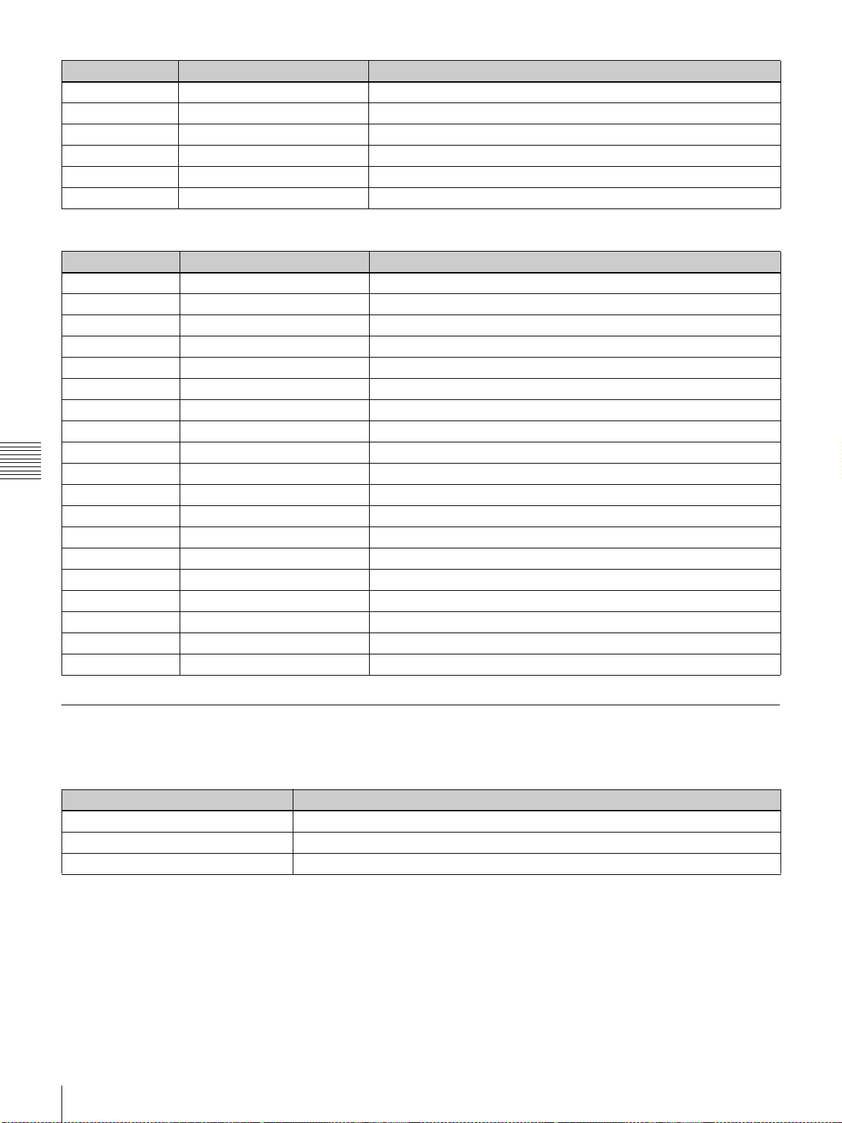
Message number Error message Meaning
WARN_27 BALLAST ERROR Failure of the ballast communication for the lamp power
WARN_28 BALLAST ERROR Incorrect settings of the lamp S/N
WARN_30 COVER DETACHED Filter duct is detached
WARN_31 FAN ERROR Abnormal in fan for PS2
WARN_32 FAN ERROR Abnormal in fan for PS1
WARN_33 FAN ERROR Abnormal in fan for PBS
FAILURE: Danger level – Low
Message number Error message Meaning
FAIL_02 TEMPERATURE ERROR Warning for abnormal temperature of 8-inch duct
FAIL_04 TEMPERATURE ERROR Temperature of the intakes is too high.
FAIL_06 TEMPERATURE ERROR Temperature of the optical unit area is too high.
FAIL_10 TEMPERATURE ERROR Warning for abnormal temperature of Panel R
FAIL_11 TEMPERATURE ERROR Warning for abnormal temperature of Panel G
FAIL_12 TEMPERATURE ERROR Warning for abnormal temperature of Panel B
FAIL_15 TEMPERATURE ERROR Warning for abnormal temperature of the lamp power
FAIL_16 LENS ERROR Failure of the zoom position adjustment to the registered setting
FAIL_17 LENS ERROR Failure of the lens focus adjustment to the registered setting
FAIL_18 LENS ERROR Trouble with the zoom position adjustment
Chapter 5 Others
FAIL_19 LENS ERROR Trouble with the lens focus adjustment
FAIL_21 ADJUSTMENT ERROR Abnormal in the Z-axis adjustment
FAIL_25 DEVICE ERROR Failure of FPGA configuration
FAIL_26 DEVICE ERROR Trouble with the IIC circuit
FAIL_27 DEVICE ERROR Trouble with the LVDS circuit
FAIL_28 DEVICE ERROR Trouble with the PLL circuit
FAIL_29 DEVICE ERROR Trouble with the PARITY circuit
FAIL_30 BALLAST ERROR Lamp power interlocked
FAIL_36 DEVICE ERROR Error of the DVI setting
Information Messages
The message number is not displayed for information messages. Check the following if a message appears in the STATUS
MESSAGE window.
Message Meaning
LOW REAL TIME CLOCK BATTERY The RTC battery (BT200) for the SY board should be replaced.
LAMP ALERT The recommended usage time of the projection lamp has passed.
AIR FILTER WARNING OPTICAL The recommended usage time of the optical air filter has passed.
68
Messages
Page 69
Specifications
Optical characteristics
Projection system
SXRD (Silicon X-tal Reflective Display)
3 panel prism color integration system
SXRD 8,847,360 pixels (4096 × 2160 × 3)
Lens Optional
Light output 23,000 lm (center)
30,000 lm (center, during HBM
Lamp 4.2 kW Xenon lamp (not supplied)
1) When using the supplied High Brightness Mode filter. For details, contact
your dealer or your local Sony representative.
Electrical characteristics
Acceptable signal
XGA, Quad-VGA, SXGA, SXGA+,
UXGA, WUXGA, 1920 × 1080, 2048
× 1080 (when the LKRI-005 HDCP
DVI input board is installed)
HD-SDI (SMPTE Serial Digital Interface
standard) (when the LKRI-003 HD-
SDI (4:4:4) input board is installed)
Input/Output
DVI-D DVI connector, 24-pin (male) (For
details, see “Pin assignment” on page
70.)
AUX DVI connector, 24-pin (male) (For
details, see “Pin assignment” on page
70.)
RS-232C D-sub 9-pin (female) (For details, see
“Pin assignment” on page 70.)
ETHERNET 10BASE-T/100BASE-T
Input signal
Preinstalled board (LKRI-005)
XGA, Quad-VGA, SXGA, SXGA+,
UXGA, WUXGA, 1920 × 1080, 2048
× 1080
When the LKRI-003 is installed
SMPTE Format HD-SDI/DC-SDI/Dual-
link HD-SDI/Dual-link DC-SDI
When the LKRI-005 is installed
XGA, Quad-VGA, SXGA, SXGA+,
UXGA, WUXGA, 1920 × 1080, 2048
× 1080
1)
)
General
Dimensions Approx. 700 × 640 × 1250 mm (27 5/8 ×
Mass Approx. 181 kg (399 lb) (excluding the
Power requirements
Power consumption
Current consumption
Operating temperature
Performance guarantee temperature
Operating humidity
Storage temperature
Storage humidity
Supplied accessories
1
25
/4 × 49 1/4 inches) (w/h/d)
(excluding the optional lens and main
unit’s projecting parts)
optional lamp and lens)
200 V to 240 V AC, 50/60 Hz
Max. approx. 5.6 kW
(Standby mode: 29 W)
28 A to 23.4 A
5°C to 35°C (41°F to 95°F) (About 20
minutes of aging is recommended to
provide better quality picture.)
10°C to 30°C (50°F to 86°F)
35% to 85% (no condensation)
–20°C to +60°C (–4°F to +140°F)
10% to 90%
Ethernet cable (Câble Ethernet)
(1-830-803-12 (Sony)) (1)
Lens cover (1 set)
M8 screws for lens mounting (4)
Attachment board for the LKRI-003 (4)
Attachment board for the LKRI-005 (3)
Keys (4)
High Brightness Mode filter (1 set)
Operating Instructions (this document, 1)
Optional accessories
Projection lamp
LKRX-2042A
HD-SDI (4:4:4) input board
LKRI-003 (HD-SDI input/output with 4
BNC-type connectors)
HDMI input board
LKRI-006
HDCP DVI input board
LKRI-005 (2DVI-D input connectors)
Projection lens LKRL-Z140, LKRL-Z211, LKRL-Z214,
LKRL-Z219, LKRL-A002,
LKRL-A003, LKRA-005, LKRA-006
(For details, refer to the Operating
Instructions of each projection lens.)
3D filter LKRA-005, LKRA-006
Chapter 5 Others
Specifications
69
Page 70
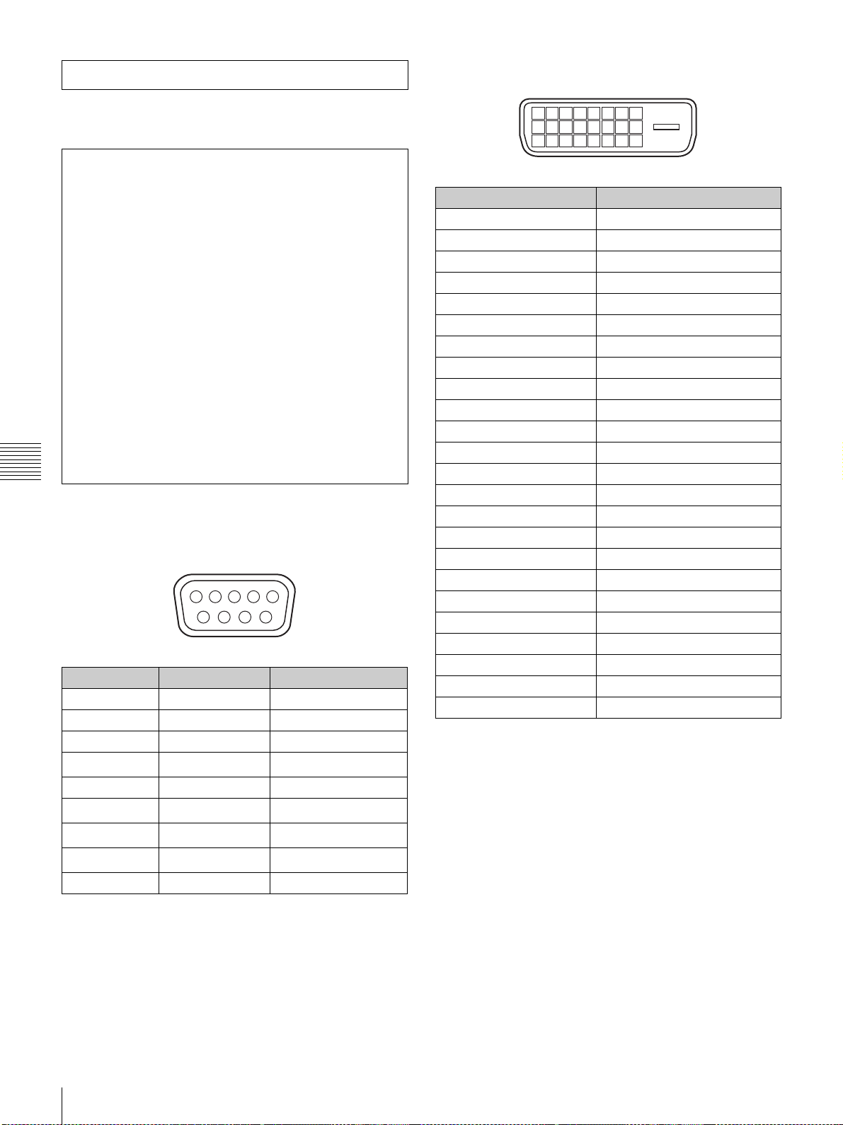
Equipment complying with IEC 61000-3-12
DVI-D connector, AUX connector (24-pin, male)
Design and specifications are subject to change without
notice.
Notes
• Always verify that the unit is operating properly
before use. SONY WILL NOT BE LIABLE FOR
DAMAGES OF ANY KIND INCLUDING, BUT
NOT LIMITED TO, COMPENSATION OR
REIMBURSEMENT ON ACCOUNT OF THE
LOSS OF PRESENT OR PROSPECTIVE PROFITS
DUE TO FAILURE OF THIS UNIT, EITHER
DURING THE WARRANTY PERIOD OR AFTER
EXPIRATION OF THE WARRANTY, OR FOR
ANY OTHER REASON WHATSOEVER.
• SONY WILL NOT BE LIABLE FOR CLAIMS OF
ANY KIND MADE BY USERS OF THIS UNIT OR
MADE BY THIRD PARTIES.
• SONY WILL NOT BE LIABLE FOR THE
TERMINATION OR DISCONTINUATION OF
ANY SERVICES RELATED TO THIS UNIT THAT
MAY RESULT DUE TO CIRCUMSTANCES OF
Chapter 5 Others
ANY KIND.
Pin assignment
RS-232C connector (D-sub 9-pin, female)
12345
6789
Pin number Signal name Meaning
1NC
2 RD Received Data
3 TD Transmit Data
4
DTR
1)
5 GND Ground
6
7
8
DSR
RTS
CTS
1)
2)
2)
9NC
1)
Circuit between pins 4 and 6 is short-circuited in the projector.
2)
Circuit between pins 7 and 8 is short-circuited in the projector.
Data Terminal Ready
Data Set Ready
Request to Send
Clear to send
1
2
3
4
5
6
7
9
10
11
12
17
13
18
19
20
21
8
14
15
16
22
23
24
Pin number Signal name
1DATA2–
2DATA2+
3 GND
4DATA4–
5DATA4+
6 DDC_SCL
7 DDC_SDA
8NC
9DATA1–
10 DATA1+
11 GND
12 DATA3–
13 DATA3+
14 +5V
15 DDC_GND
16 HOTPLUG_DET
17 DATA0–
18 DATA0+
19 GND
20 DATA5–
21 DATA5+
22 GND
23 CLK+
24 CLK–
70
Specifications
Page 71
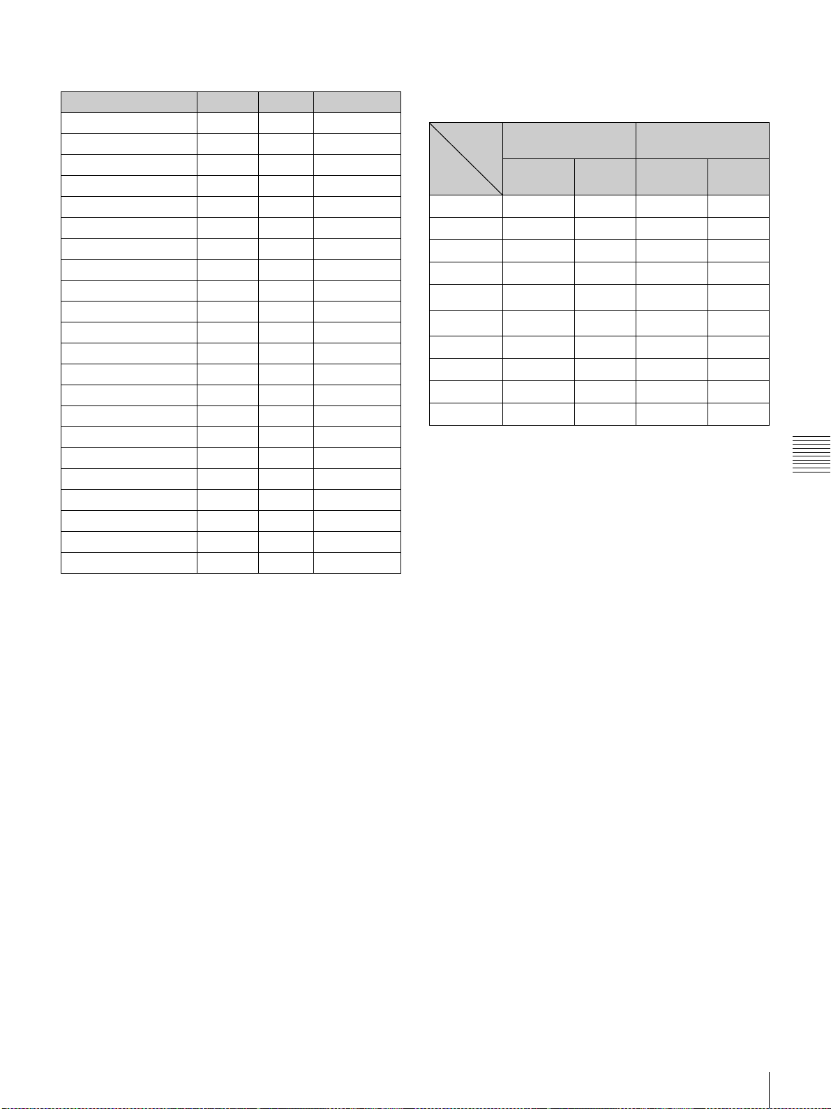
Preset Signals Displayed image size in multiple screen
mode
Preset signal fH (kHz) fV (Hz) Aspect ratio
HDTV 33.75 60.00 16:9
1024 × 768_VESA60 48.36 60.00 4:3
1024 × 768_VESA70 56.48 70.07 4:3
1024 × 768_VESA75 60.02 75.03 4:3
1024 × 768_VESA85 68.68 85.00 4:3
1280 × 960_VESA60 60.00 60.00 4:3
1280 × 1024_VESA60 63.97 60.01 5:4
1280 × 1024_VESA75 79.98 75.03 5:4
1280 × 1024_VESA85 91.15 85.02 5:4
1600 × 1200_VESA60 75.00 60.00 4:3
720/60P 45.00 60.00 16:9
720/50P 37.50 50.00 16:9
1080/48I (24PsF) 27.00 48.00 16:9
1080/50I 28.13 50.00 16:9
1080_24P 27.00 24.00 16:9
DC2048 × 1080_48I 27.00 48.00 –
DC2048 × 1080_24P 27.00 24.00 –
1400 × 1050_60p 65.30 60.00 4:3
1920 × 1080_60p 67.50 60.00 16:9
1920 × 1200_60p 74.038 60.00 –
2048 × 1080_48p 54.00 48.00 –
2048 × 1080_60p 67.50 60.00 –
Unit: pixel
Screen
mode
Type
of signal
XGA 2849 2137 1432 1074
SXGA1 2560 2048 1280 1024
SXGA2 2560 1920 1280 960
SXGA+ 2800 2100 1400 1050
1)
UXGA
WUXGA
720p 3810 2143 1916 1077
HD 3840 2160 1920 1080
2K 4096 2160 2048 1080
4K 4096 2160 – –
1)
When projecting signals with vertical frequency of more than
1080 pixels such as UXGA and WUXGA in quad-screen mode, a
part of the displayed image may be invisible.
Single screen Quad screen
Horizontal
size
2864 2148 – –
1)
3437 2148 – –
Vertical
size
Horizontal
size
Vertical
size
Chapter 5 Others
Specifications
71
Page 72
Index
Numerics
3D Resolution Format 59
A
Adjustments and Settings Using the
SRX Controller 58
B
Board 59, 60
Brightness 60
C
Color 60
Color Space 60
Color Temp 61
COLOR/FRAME window 60
Connection mode 53
Connections
Chapter 5 Others
computer equipped with a DVI-D
connector 53
computer for controlling the
projector 50
HD-SDI equipment 54
Contrast 60
Control Function Menu window 44,
58
CUT OFF 46
H
H Shift 61
H Size 61
I
I/P Mode 59
IMAGE FLIP 62
INPUT SELECT 45, 56
Input Signals And Adjustable/Setting
Items 63
Input Source 59
INSTALLATION window 62
L
LAMP POWER 62
LENS CONTROL 62
Location and Function of Controls
Control Function Menu window
44
Front/Sides 43
Rear 44
M
Maintenance 64
MASKING ADJUST 45
Messages 66
MUTING 46, 56
O
Operation Timer 45
Optional accessories 69
S
Save Log 44
SCREEN CONTROL window 45
Sharpness 60
Signal Adjust 60, 63
Signal Info 59
Signal Mode 59
Specifications 69
SQUEEZE 62
SRX Controller
Adjustments and settings 58
Exiting 52
Installing 48
Starting 52
STATUS MESSAGE window 66
Supplied accessories 69
T
TEST PATTERN 63
Troubleshooting 65
V
V Shift 61
Ventilation holes 44
Z
Zoom 62
D
Displayed image size in multiple
screen mode 71
Dot Phase 61
E
ELECTRIC SHIFT FUNCTION 62
Error Messages 66
Ethernet connector 50
F
fH 59
Focus 56, 62
Frame Adjust 61, 63
FUNCTION 1-7 58
fV 59
G
Gamma 61
P
PICTURE CONTROL window 59
Precautions 41
Program Launcher screen 52
PROGRESSIVE DISPLAY MODE
62
Projecting a 4K Signal in Quad-screen
Mode 56
Projecting the Picture 55
Q
Quad-screen Mode 45, 56
R
Recommended Replacement Time 64
Registering the settings 58
Resetting the settings 58
RS-232C connector 51, 70
72
Index
Page 73
Trademarks
• Microsoft, Windows, and Windows
Vista are trademarks or registered
trademarks of Microsoft
Corporation in the United States
and other countries.
• Intel and Pentium are registered
trademarks of Intel Corporation in
the United States and other
countries.
• The terms HDMI and HDMI HighDefinition Multimedia Interface,
and the HDMI Logo are
trademarks or registered
trademarks of HDMI Licensing
LLC in the United States and other
countries.
• Other products or system names
appearing in this document are
trademarks or registered
trademarks of their respective
owners.
Further, the ® or ™ symbols are not
used in the text.
Chapter 5 Others
• Reproduction or duplication, in
whole or part, of the operation
manual supplied with the system
without the authorization of the
right holder is prohibited under
copyright law.
• Sony assumes no responsibility
for damages, loss of income, or
any claims from a third party
arising out of use of the system.
• Note that the specifications of the
system are subject to change for
improvement without prior
notice.
Index
73
 Loading...