

Sony SPP-SS960 Service Manual
SPP-SS960
SERVICE MANUAL
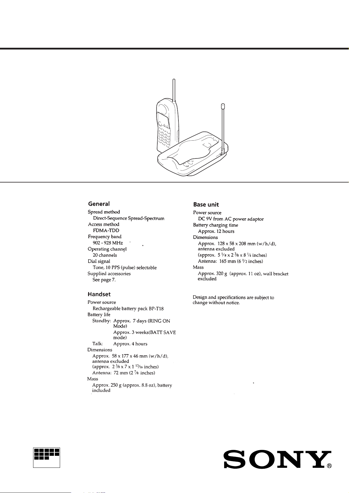
SPECIFICATIONS
US Model
Canadian Model
MICROFILM
CORDLESS TELEPHONE

TABLE OF CONTENTS
SERVICING NOTES
1. GENERAL
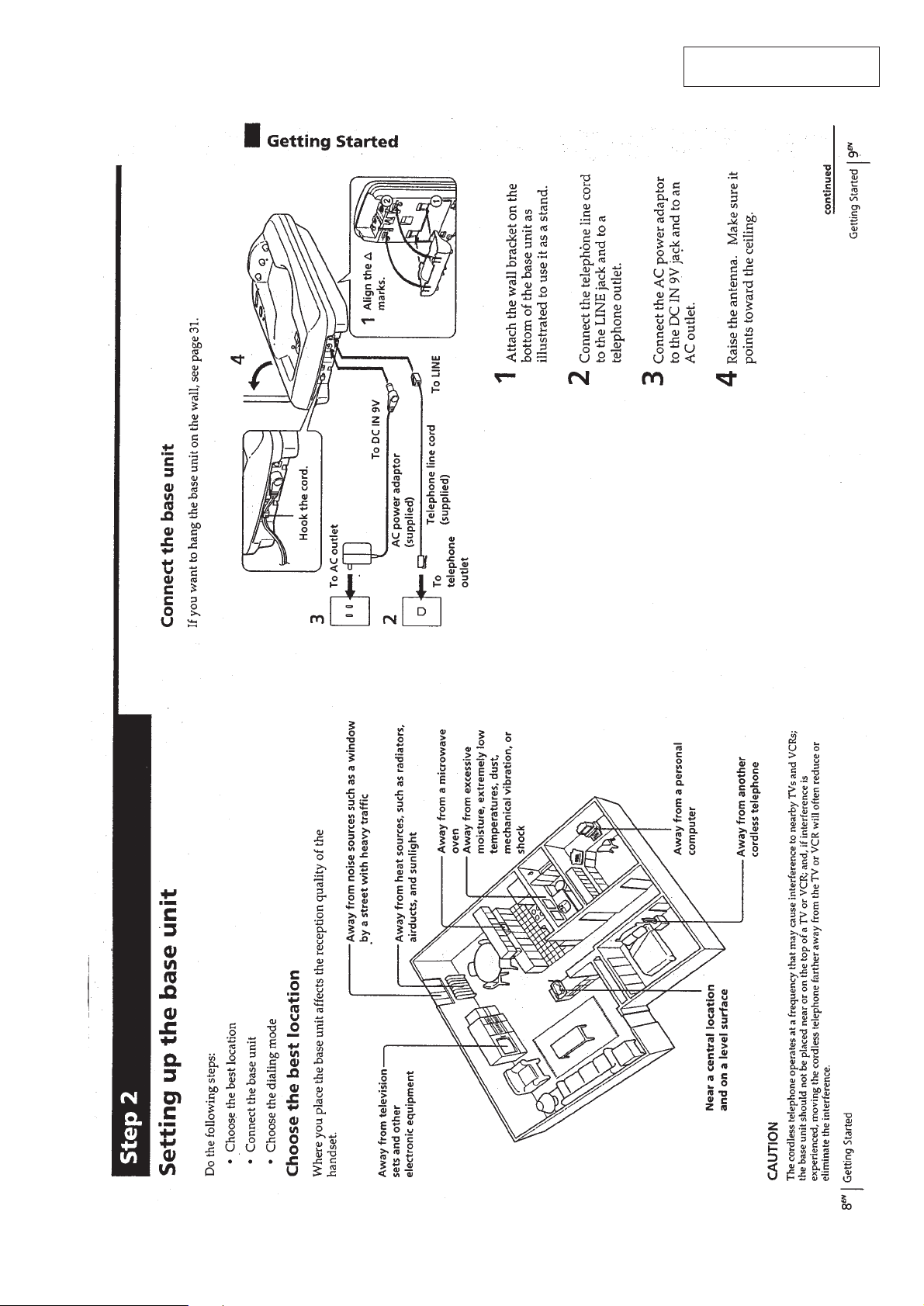
Setting up the base unit.................................................... 3
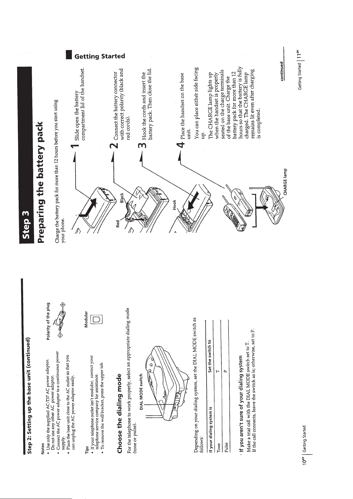
Preparing the battery pack ............................................... 4
Entering your area code................................................... 5
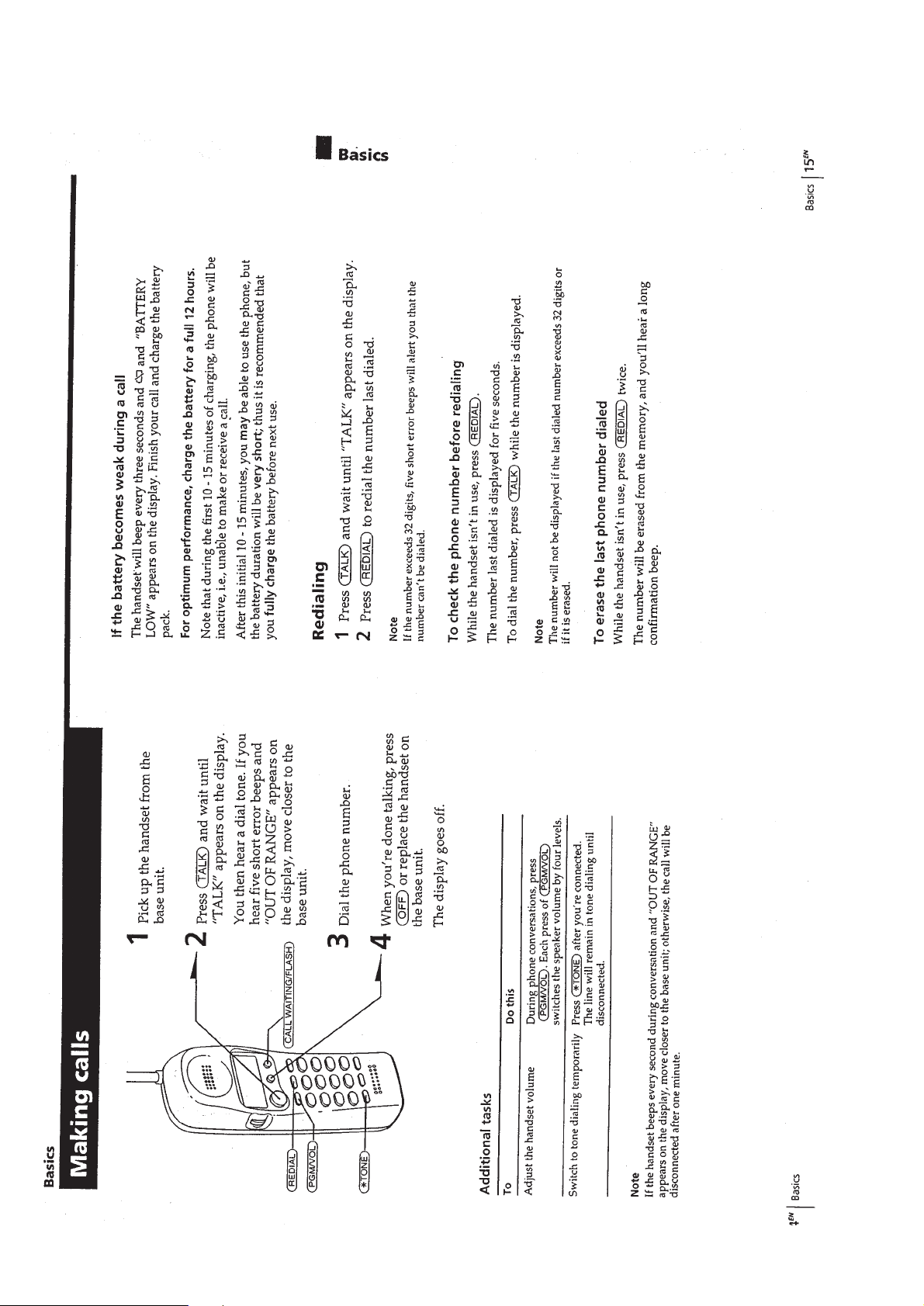
Making calls .................................................................... 6
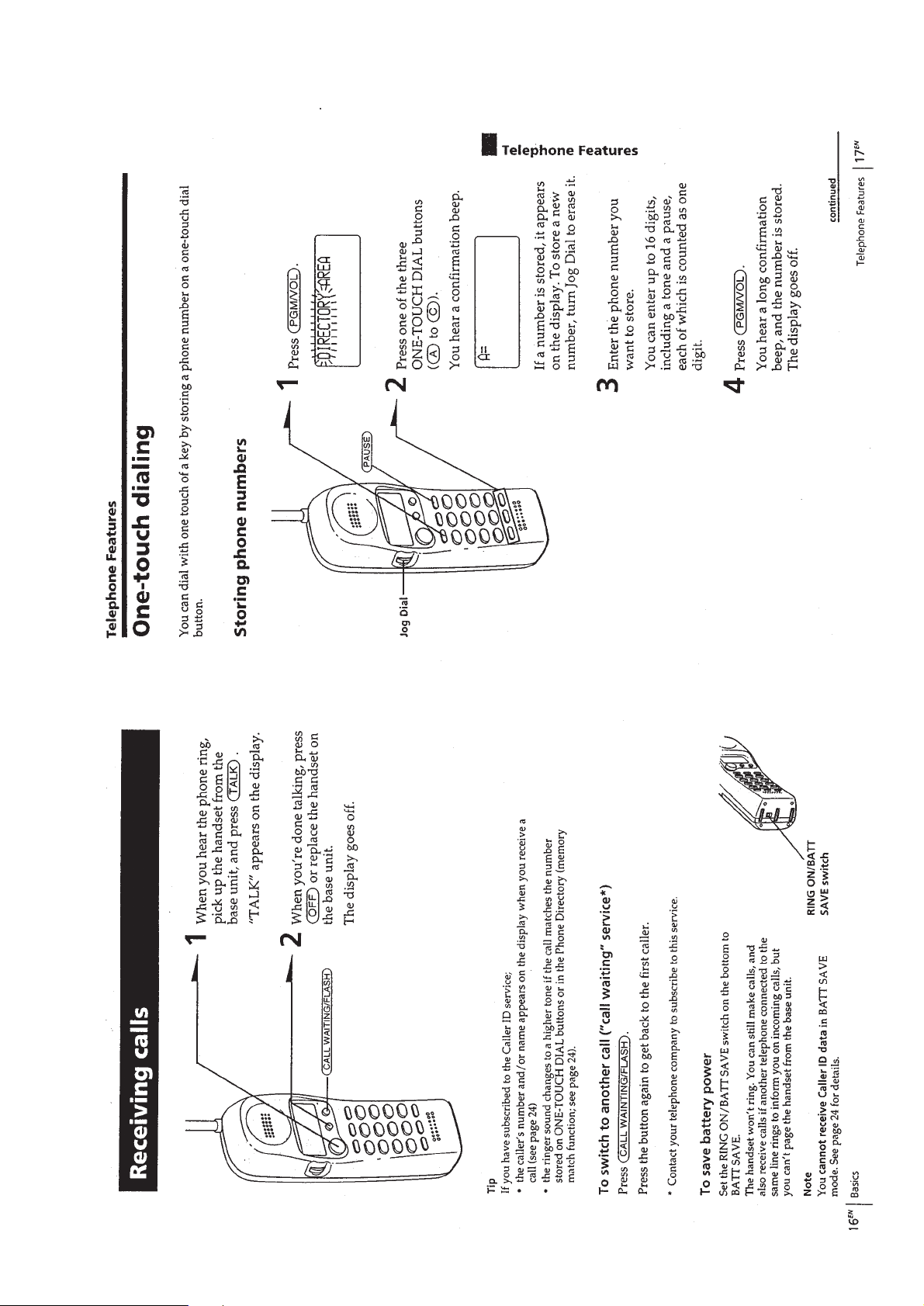
Receiving calls................................................................. 7
One-touch dialing ............................................................ 7
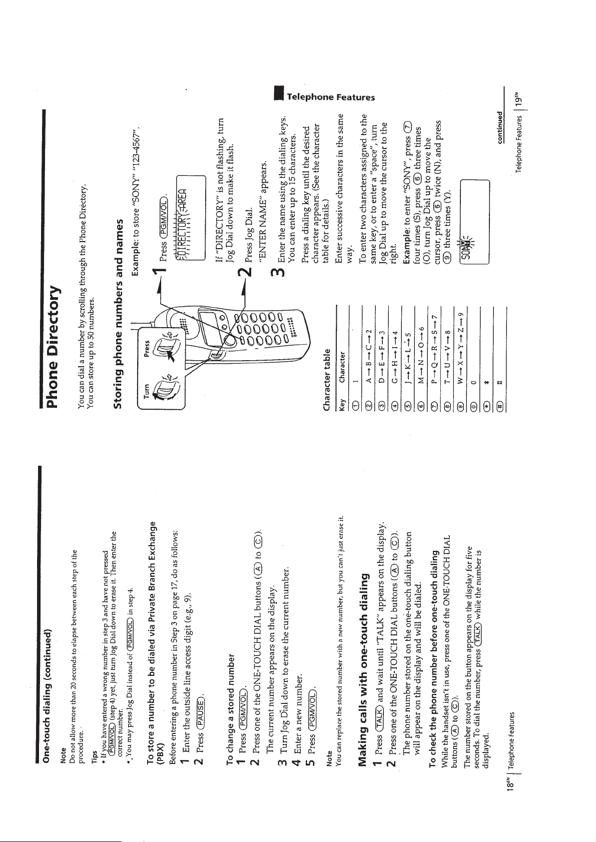
Phone Directory............................................................... 8
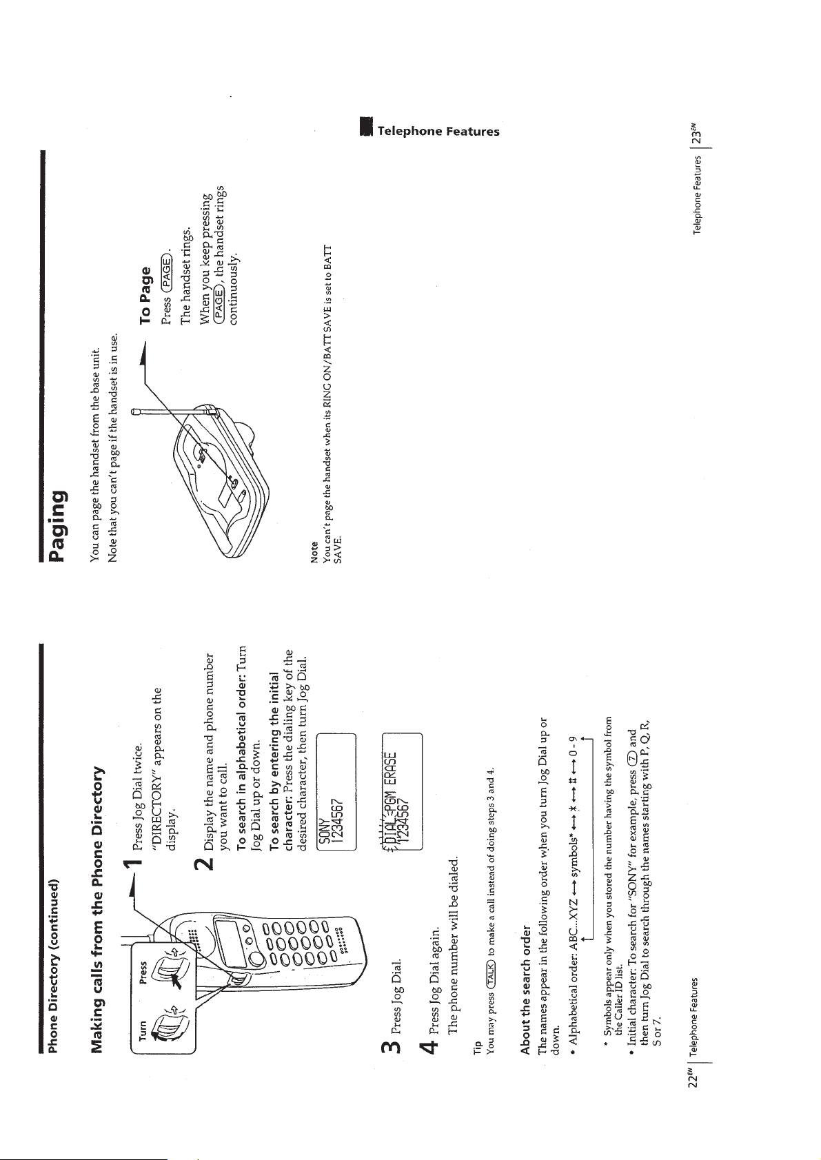
Paging .............................................................................. 10
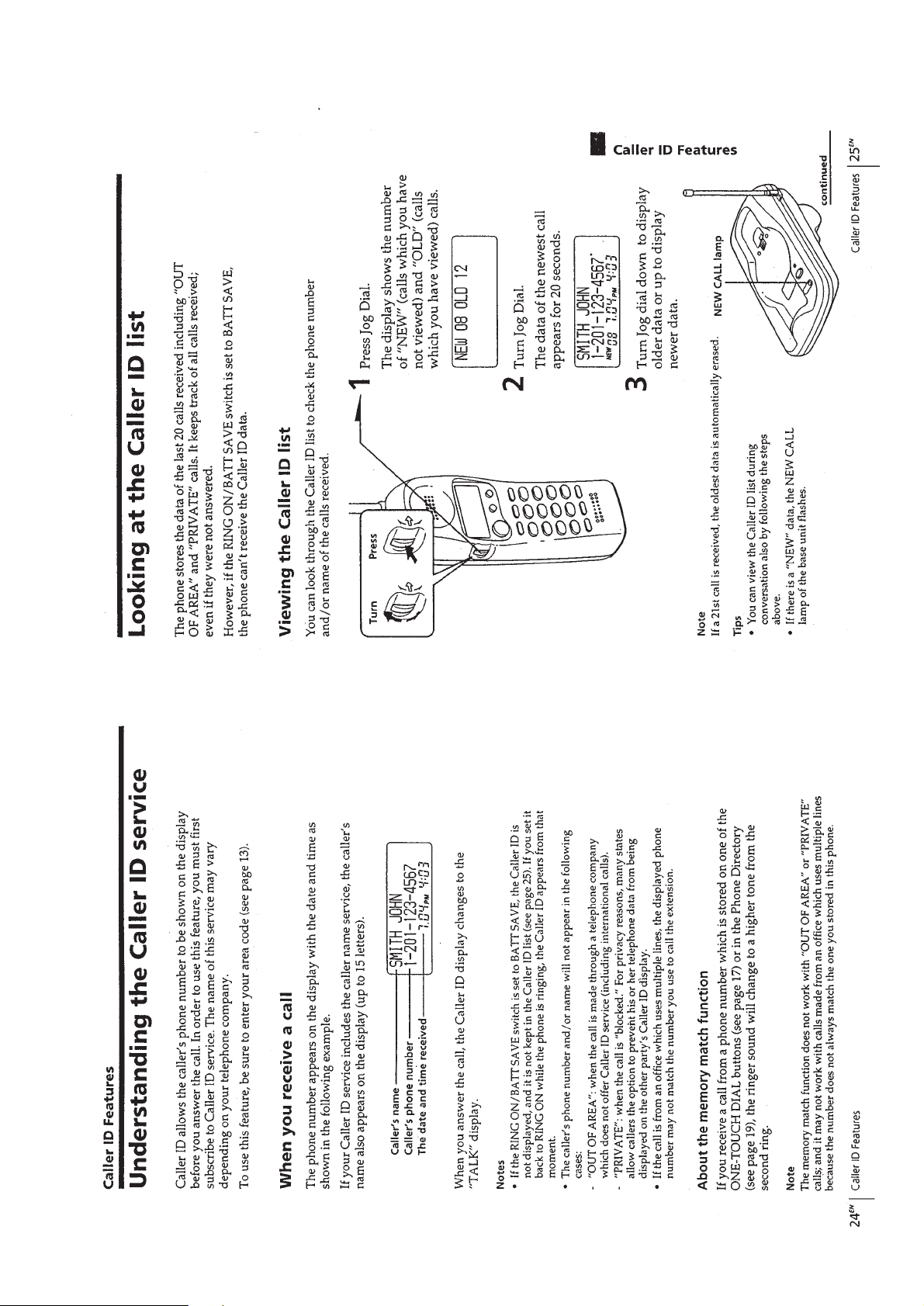
Understanding the Caller ID service ............................... 11
Looking at the Caller ID list ............................................11
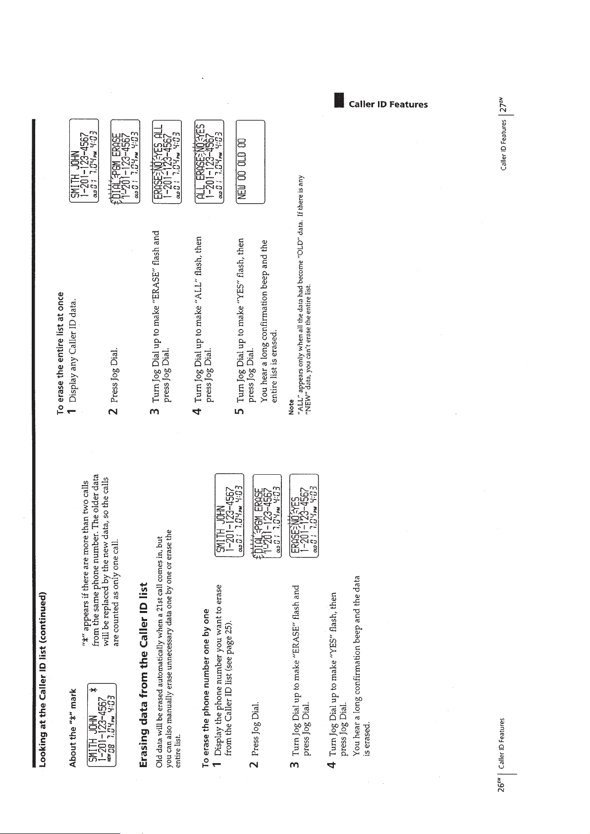
Using the Caller ID list .................................................... 13
Using “Caller ID with call waiting” service.................... 14
Mounting the base unit on a wall .................................... 14
2. DISASSEMBLY.......................................................... 15
3. 900MHz SYSTEM OPERATION
3-1. Access Method ................................................................ 17
3-2. Protocol............................................................................ 17
4. TEST MODE
4-1. Base Unit Test Mode A....................................................20
4-2. Base Unit Test Mode B.................................................... 20
4-3. Handset T est Mode .......................................................... 21
5. ELECTRICAL ADJUSTMENTS
5-1. Base Unit Section ............................................................ 22
5-2. Handset Section ............................................................... 23
Notes on chip component replacement
• Never reuse a disconnected chip component.
• Notice that the minus side of a tantalum capacitor may be dam-
aged by heat.
6. DIAGRAMS
6-1. Schematic Diagram – Base Unit Section –...................... 26
6-2. Printed Wiring Boards – Base Unit Section – ................. 29
6-3. Printed Wiring Board – Handset Section –...................... 31
6-4. Schematic Diagram – Handset Section – ........................ 33
6-5. IC Pin Function Description ............................................37
7. EXPLODED VIEWS ................................................ 41
8. ELECTRICAL PARTS LIST................................ 43
SAFETY-RELATED COMPONENT WARNING!!
COMPONENTS IDENTIFIED BY MARK ! OR DOTTED LINE
WITH MARK ! ON THE SCHEMATIC DIAGRAMS AND IN
THE PARTS LIST ARE CRITICAL TO SAFE OPERATION.
REPLACE THESE COMPONENTS WITH SONY PAR TS WHOSE
PART NUMBERS APPEAR AS SHOWN IN THIS MANUAL
OR IN SUPPLEMENTS PUBLISHED BY SONY.
ATTENTION AU COMPOSANT AYANT RAPPORT
À LA SÉCURITÉ!
LES COMPOSANTS IDENTIFIÉS P AR UNE MARQ UE ! SUR
LES DIAGRAMMES SCHÉMATIQUES ET LA LISTE DES
PIÈCES SONT CRITIQUES POUR LA SÉCURITÉ DE
FONCTIONNEMENT . NE REMPLACER CES COM- POSANTS
QUE P AR DES PIÈCES SONY DONT LES NUMÉR OS SONT
DONNÉS DANS CE MANUEL OU D ANS LES SUPPLÉMENTS
PUBLIÉS PAR SONY.
– 2 –
SECTION 1
GENERAL
This section is extracted from
instruction manual.
– 3 –
– 4 –

– 5 –
– 6 –
– 7 –
– 8 –
– 9 –
– 10 –
– 11 –
– 12 –
 Loading...