

Sony SPP-S9003 Service Manual
SPP-S9003
SERVICE MANUAL
SPECIFICATIONS
E Model
MICROFILM
CORDLESS TELEPHONE
1

TABLE OF CONTENTS
1. GENERAL .......................................................................... 3
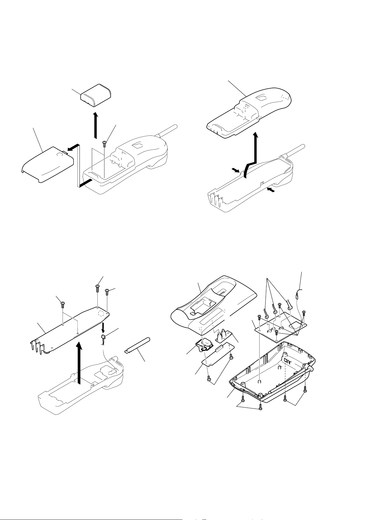
2. DISASSEMBLY
2-1. Battery Case LID (Handset).................................................. 6
2-2. Cabinet (Rear) (Handset) ...................................................... 6
2-3. Hand Main Board (Handset) ................................................. 6
2-4. Cabinet and Boards (Base Unit) ........................................... 6
Notes on chip component replacement
• Never reuse a disconnected chip component.
• Notice that the minus side of a tantalum capacitor may be
damaged by heat.
3. 900 MHz SYSTEM OPERATION
3-1. Access Method...................................................................... 7
3-2. Protocol ................................................................................. 7
4. TEST MODE
4-1. Base Unit Test Mode A ....................................................... 10
4-2. Base Unit Test Mode B ....................................................... 11
4-3. Handset T est Mode.............................................................. 12
4-4. RF Testing........................................................................... 13
5. ELECTRICAL ADJUSTMENTS
5-1. Base Unit Section................................................................ 16
5-2. Handset Section .................................................................. 17
6. DIAGRAMS
6-1. IC Block Diagram ............................................................... 19
6-2. Printed Wiring Board – Base Unit Section – ...................... 20
6-3. Schematic Diagram – Base Unit (1/2) Section – ................ 22
6-4. Schematic Diagram – Base Unit (2/2) Section – ................ 23
6-5. Printed Wiring Board – Handset Section – ......................... 24
6-6. Schematic Diagram – Handset Section –............................ 25
6-7. IC Pin Functions ................................................................. 26
7. EXPLODED VIEWS
7-1. Handset Section .................................................................. 29
7-2. Base Unit Section................................................................ 30
SAFETY-RELATED COMPONENT WARNING !!
COMPONENTS IDENTIFIED BY MARK ! OR DO TTED LINE
WITH MARK ! ON THE SCHEMATIC DIAGRAMS AND IN
THE PARTS LIST ARE CRITICAL TO SAFE OPERATION.
REPLACE THESE COMPONENTS WITH SONY PARTS
WHOSE PART NUMBERS APPEAR AS SHOWN IN THIS
MANUAL OR IN SUPPLEMENTS PUBLISHED BY SONY.
8. ELECTRICAL PARTS LIST ........................................ 31
2
SECTION 1
GENERAL
This section is extracted from
instruction manual.
3
456
SECTION 2
DISASSEMBLY
Note: Follow the disassembly procedure in the numerical order given.
2-1. BATTERY CASE LID (HANDSET)
Nickel cadmium battery
Battery case lid
2
1
3
2-2. CABINET (REAR)(HANDSET)
Cabinet (rear)
Two screws (BTP 2.6x8)
2
1
1
2-3. HAND MAIN BOARD (HANDSET)
Screw (BTP 2.6x12)
2
Two screws (BTP 2.6x8)
1
Hand main board
4
3
5
Screw (BTP 2.6x8)
Connector (CN601)
Helical antenna
2-4. CABINET AND BOARDS (BASE UNIT)
6
5
Cabinet (Upper)
!¡
Button (H.L.)
0
LED board
9
T wo screws
(BTP2.6x8)
3
Cabinet (Lower) assy
2
T wo screws
(P3x10)
4
Three connectors
8
Base (Main)
board
!™
Lens
(Basic)
Antenna terminal
7
Four screws
(P3x10)
1
T wo screws
(P3x10)
SECTION 3
BASE UNIT HANDSET
System ID
confirmed
System ID
confirmed
(Park Detect)(Park Detect)
(PARK)
System Parameters
A-Frame
A-Frame
900 MHz SYSTEM OPERATION
3-1. ACCESS METHOD
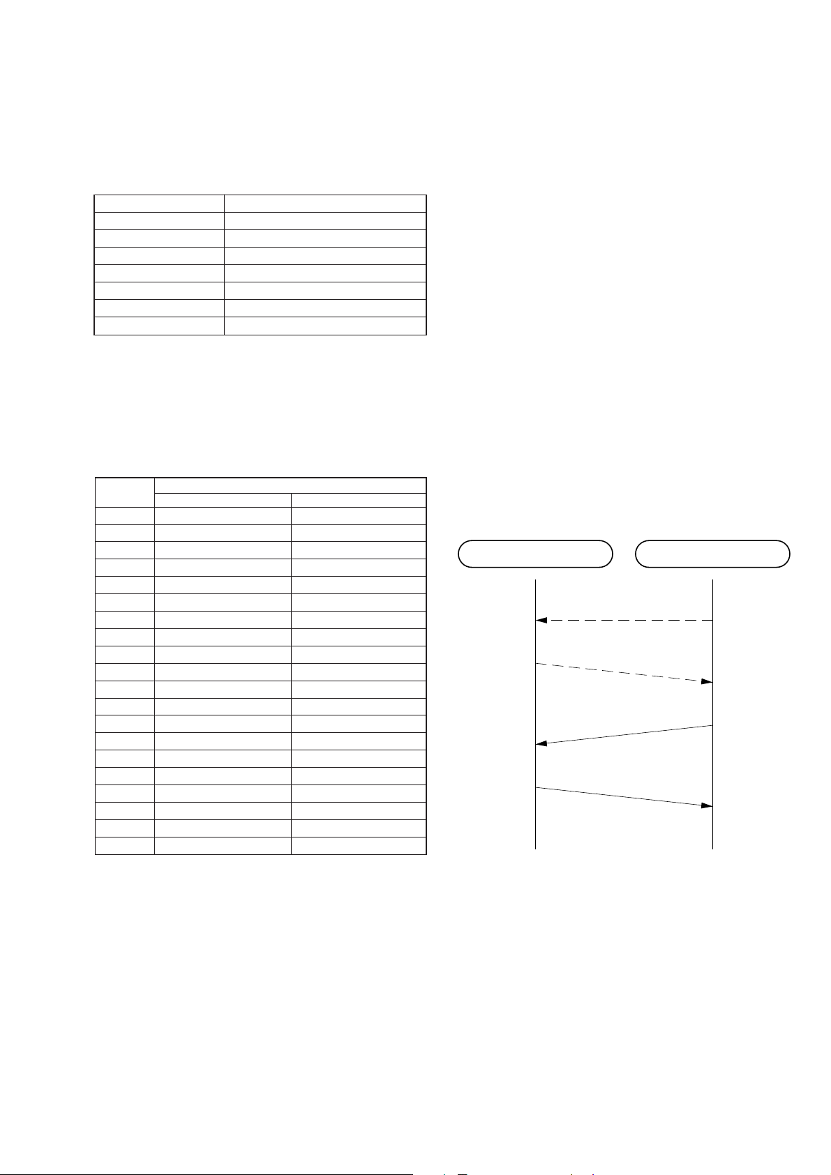
1. Transfer format & rate
The transfer format & rate of our system is as follows;
Table 3-1. Transfer method
Access method FDMA-TDD
Channel number 14 channel
Channel spacing 1.2 MHz
Modulation method DBPSK
Baseband transfer rate 960 Kbps
Spread method Direct Sequence Spread Spectrum
Chip rate 12 chips/bit
Data transfer rate 80 Kbps
2. Channel Number & Frequencies
RF channels occupy the frequency band 902 – 928 MHz are numbered 1 to 14.
RF channel numbers & center frequencies are specified as follows.
Table 3-2. Channel number & Channel frequency
Channel Channel Center Frequency (MHz)
Number UNIT CH PLAN TEST MODE CH PLAN
1 907.2 904.2
2 908.4 904.8
3 909.6 906.0
4 910.8 907.2
5 912.0 908.4
6 913.2 909.6
7 914.4 910.8
8 915.6 912.0
9 916.8 913.2
10 918.0 914.4
11 919.2 915.6
12 920.4 916.8
13 921.6 918.0
14 922.8 919.2
15 920.4
16 921.6
17 922.8
18 924.0
19 925.2
20 925.8
*Note) The UNIT has 14 channels according to the UNIT CH
PLAN while the number of channels which can be used in
the test mode are those in the TEST MODE CH PLAN.
3-2. PROTOCOL
1. General
This system realizes the TX/RX superframe by TDD system. The
relation of master/slave dose not decide identification regarding
the protocol between BASE UNIT and HANDSET, but the initiated side is the master and the requested side is the slave when the
RF link has been established.
2. Initial acquisition
In order to establish the RF link between BASE UNIT and HANDSET, both of BASE UNIT and HANDSET need to have the same
system ID. When “power” is applied to this system, the system
have to do Initial Acquisition in order to hav e the same system ID.
It is to exchange a parameter when the HANDSET is parked on
the BASE UNIT , as soon as the system do System P arameters Reinitialization.
3. System parameter re-initialization
This System Parameters Re-initialization can realize that the
HANDSET is parked on the BASE UNIT . So after the B ASE UNIT
recognized to be parked the HANDSET, the BASE UNIT calculates a system parameter, and then it outputs this data from the
ARTO port, and then the system establishes the RF link. In order
to establish this link, the HANDSET send the A-Frame to the B ASE
UNIT after the HANDSET received the system parameter, and
then the BASE UNIT send the A-Frame to the HANDSET. The
process of System Parameters Re-initialization is as follows.
Fig. 3-1. System Parameters Re-initialization
7
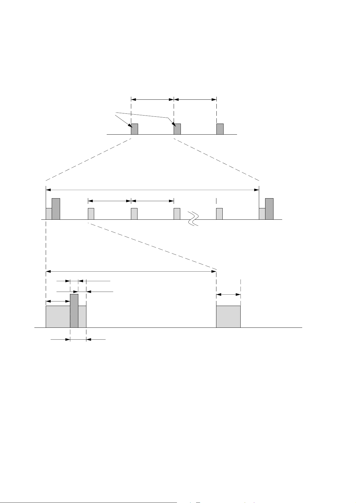
4. Stand-by Mode Operation
(1) HANDSET
When the HANDSET is the stand-by mode (sleep mode), the
HANDSET do the intermittent operation for power save, because the HANDSET is the battery operation.
This process of stand-by mode operation is as follows.
10 sec
Heart-Beat
10 sec
Heart-Beat Heart-Beat
RX RX RX RX RX
1 sec 1 sec
RX
10 sec
1 sec
2 msec
2 msec 10 msec
10 msec
RXTXRX
Heart Beat
(Exchange A-Frame for Link confirmation purpose)
Fig. 3-2. Stand-by mode operation (HANDSET)
(2) BASE UNIT
The BASE UNIT is supplied the power by AC line. W hile the
BASE UNIT is the stand-by , the BASE UNIT is al ways a wake
state. While the BASE UNIT monitors the current channel,
the BASE UNIT monitors also the other channel at the same
time
Because if the current channel can not use by some interference, the system needs the clear channel information as a part
of system parameter for a channel hop.
If the BASE UNIT can not receive the A-Frame of Heart-beat
from the HANDSET, it become “link error”, and the system
become error recovery mode.
RX
8
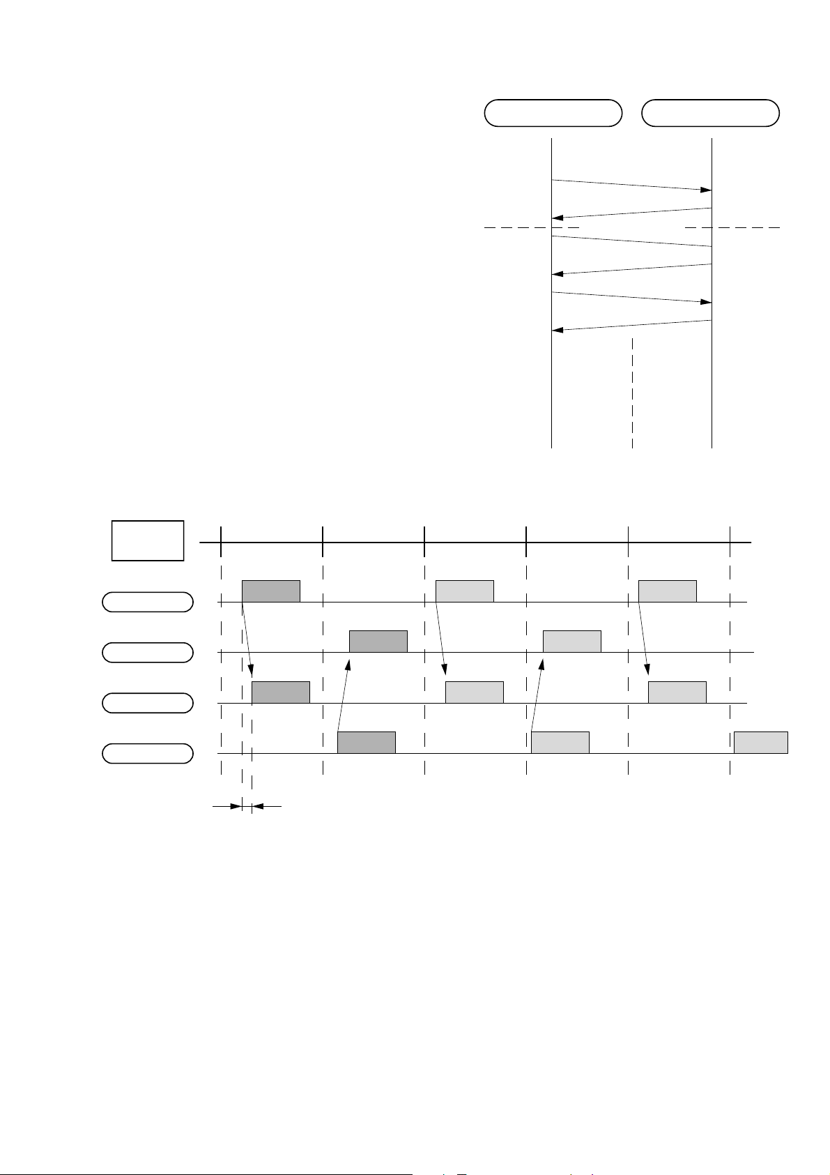
5. Link Establishment
According to the following Fig. 3-1, the requested side for link
establishment is the master.
The system have to exchange the A-Frame for link establishment,
and each system ID should be the same ID, and then the system
link is established.
The protocol and timing chart of link establishment are as follows.
Master Slave
A-Frame
System ID
confirmed
Fig. 3-3. Link Establishment protocol
A-Frame
V-Frame
V-Frame
V-Frame
V-Frame
System ID
confirmed
Master
Time Slot
Master TX
Master RX
Slave RX
Slave TX
Trip Delay
TX RX TX RX TX
AV
A' V
Fig. 3-4. Link Establishment Timing Chart
6. State Change/Tarmination
After the RF link between HANDSET and BASE UNIT was established, a movement of each state (State: ON-Hook, OFF-Hook,
PAGE, InterCom, etc) is sent through supervisory bits.
V
VA
VA'
V
V
7. Error Recovery
In case of the following situation, The system becomes “Error
Recovery Mode”.
(1) The system failed to move to “Heart-Beat” during “Stand-by
mode, or failed “link establishment”.
(2) The system failed to keep the link.
9
SECTION 4
TEST MODE
4-1. BASE UNIT TEST MODE A
Manual System Test Mode
[Start-up]
1. Set the DIAL MODE switch to P (PULSE), and turn on the
power while pressing the HANDSET LOCATOR key.
2. Change the DIAL MODE switch from P (PULSE) to T
(TONE) b P (PULSE), and release the HANDSET LOCA T OR
key to start up.
3. After starting up Test Mode A, perform dial test.
4. The TEST MODE A state will be set after the dial test.
5. In test mode idling A, pressing the HANDSET LOCA TOR ke y
with the P (PULSE)/T (TONE) switch set to P (PULSE) state
switches to BASE UNIT TEST MODE A-1.
DIAL MODE switch
P (PULSE) side
T (TONE) side
Test Mode Idle A-1
Test Mode Idle A-2
[Dial Test]
After starting BASE UNIT TEST Mode A, close the circuit for about
500 msec after start, and dial PAUSE , 0 (DP), wait 2 seconds, 1
(Tone), 4 (Tone), 8 (Tone), # (Tone) in this order.
[Ring Detect Test]
1. Rings the Normal Ringer synchronized with an external call coming in, and blinks the IC501 Pin !™ (New Call LED/VMWI LED)
at the same time.
[Charge Detection and ART0 Output Test]
1. Detects that the charge detection terminal IC501 Pin @∞ (-P ARKP)
has turned from H to L, and outputs a square waveform signal
(2.4 kbps) from the ART0 ter minal.
2. Clears the EEPROM contents at the same time.
[Charge Control Test]
1. When the IC501 Pin !• input (BATT_CHK) changes from
L, H, to L during charge detection, the IC501 Pin !¶ output
(CHRG_CTL) will output L, H, LH, L, to H only once.
[Branch Detection Test]
When the shared phone is detected to be off the hook and the Branch
detection terminal IC501 Pin (¢ (EXT_DET) detects L, the VMWI
LED is lit. When off-hook is detected and the Branch detection
terminal IC501 Pin (¢ (EXT_DET) detects H, the VMWI LED is
turned off.
Idle status
4-1-1. BASE UNIT Test Mode A-1
1. In test mode idling A and the P (PULSE)/ T (TONE) switch set
to the P (PULSE) state, pressing the HANDSET LOCATOR
key changes the mode as shown below.
2. Setting the P (PULSE)/ T (TONE) switch from P (PULSE) to T
(TONE) in the BASE UNIT test mode A-1 in any time also enables the mode to be changed to the BASE UNIT test mode
idling A.
• This mode is intended for checking that the IC501 line is operat-
ing properly. Add the LINEIN signal and check that the signal is
output to the SPEAKER OUT.
HANDSET
LOCATIOR
button
pressing
count
1
2
3
4
CODEC Forward Loopback (L1)
(Line: Talking state)
(CODEC LINE IN n SPEAKER OUT)
ADPCM Forward Loopback (L2)
(Line: Talking state)
(CODEC LINEIN n ADPCM
n CODEC SPERKER OUT)
Does not function
Returns to BASE UNIT TEST MODE • IDLING A
Test mode
Note: If the LEDs are lit due to the idling state test, clear all the
LEDs, and return to the idling state.
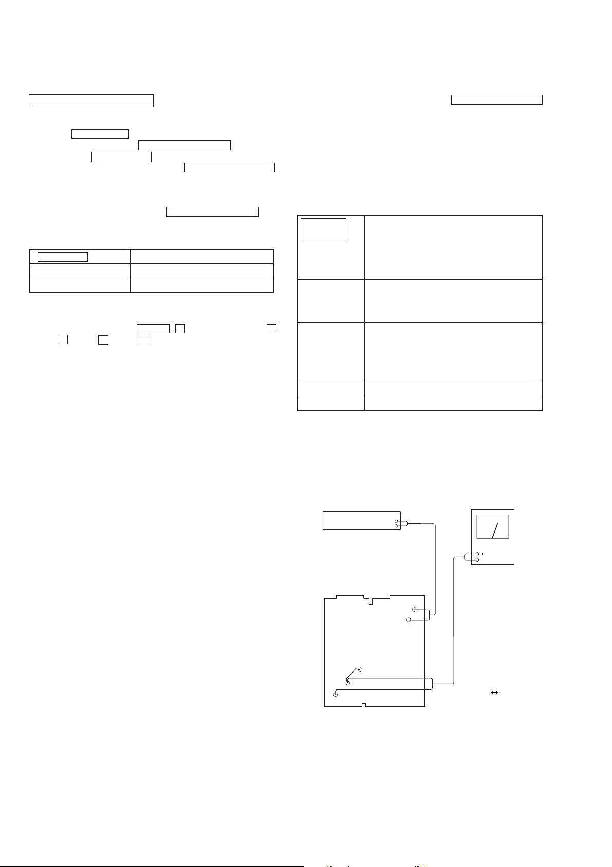
[Base Set AUDIO Input/Output Level test
[CODEC Forward Loop Back (LI) Mode]]
Audio analyzer
osc out
TP101
TP102
Level meter
10
TP911
GND
TP912
Base main mount
• Short: TP911 GND
Setting:
Setting: OSC=–13.0 dBV (Open terminal)
MOD=1 kHz
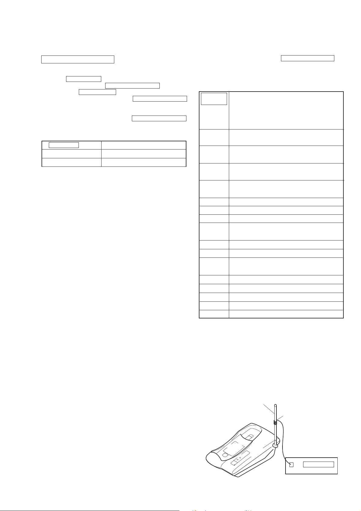
4-2. BASE UNIT TEST MODE B
ANTENNA
Pickup coil
Frequency counter
Manual System Test Mode
[Start-up]
1. Set the DIAL MODE switch to T (TONE), and turn on the
power while pressing the HANDSET LOCATOR key.
2. Change the DIAL MODE switch from T (TONE) to P
(PULSE)b T (TONE), and release the HANDSET LOCATOR
key to start up.
3. The TEST MODE B state will be set.
4. In test mode idling B, pressing the HANDSET LOCATOR
key with the P (PULSE)/T (TONE) switch set to T (T ONE) state
switches to BASE UNIT TEST MODE B-1.
DIAL MODE switch
T (TONE) side
P (PULSE) side
Test Mode Idle B-1 *1
Test Mode Idle B-2 *2
*1 Radio block: TDD mode (master timing)
Audio block: Line speech status
*2 Radio block: Standby status
Audio block: Line open
[Stutter T one Detection]
1. Monitors the stutter tone detection terminal IC501 pin (∞
(Stutte_Det) at all times and lights the VMWI LED when 5
pulses are detected like in actual operations.
Idle status
4-2-1. BASE UNIT Test Mode B-1
1. In test mode idling B with the P (PULSE)/T (TONE) switch set
to the T (TONE) state, pressing the HANDSET LOCATOR key
changes the mode as shown below.
2. Setting the P (PULSE)/T (TONE) switch from T (TONE) to P
(PULSE) in BASE UNIT test mode B-1 any time also enables
the mode to be changed to BASE UNIT test mode idling B.
HANDSET
LOCATOR
button
pressing
count
1
1ch single carrier continuous transmission mode
Radio mode
(high power)
2
10ch single carrier continuous transmission mode
(high power)
3
20ch single carrier continuous transmission mode
(high power)
4
1ch continuous transmission mode
(high power)
5
1ch continuous transmission mode (middle power)
6
1ch continuous transmission mode (low power)
7
10ch continuous transmission mode (high power)
8
10ch continuous transmission mode
(middle power)
9
10ch continuous transmission mode (low power)
10
11
20ch continuous transmission mode (high power)
20ch continuous transmission mode
(middle power)
12
13
14
15
16
20ch continuous transmission mode (low power)
1ch continuous reception mode
10ch continuous reception mode
20ch continuous reception mode
Returns to BASE UNIT TEST MODE • IDLING B
Note: If the LEDs are lit due to the idling state test, clear all the
LEDs, and return to the idling state.
4-2-2. Ending the Base Unit Test Mode
1. To end the base unit test mode, turn off the power of the base
unit.
[BASE UNIT carrier frequency measurement
[Single carrier 1CH continuous transmission]]
Setting:
Spec: 904.2 MHz ± 27KHz
11
 Loading...