

Sony SPP-205, SPP-206 Service manual
SPP-205/206
SERVICE MANUAL
SPECIFICATIONS
US Model
SPP-205
Canadian Model
E Model
SPP-206
MICROFILM
CORDLESS TELEPHONE

TABLE OF CONTENTS
1. GENERAL
Setting up the base phone ............................................... 3
Preparing the battery pack .............................................. 3
Making calls .................................................................... 4
Receiving calls ................................................................ 4
Speed dialing ................................................................... 5
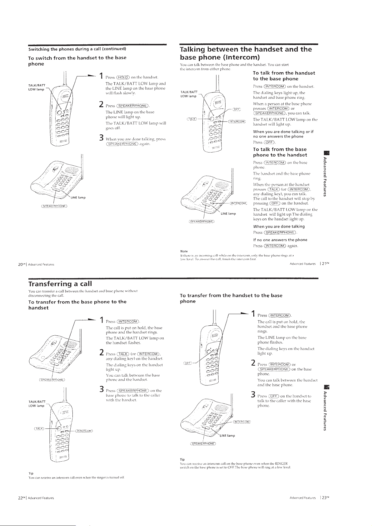
Switching the phones during a call................................. 5
Talking between the handset and
the base phone (Intercom) .............................................. 6
Transferring a call ........................................................... 6
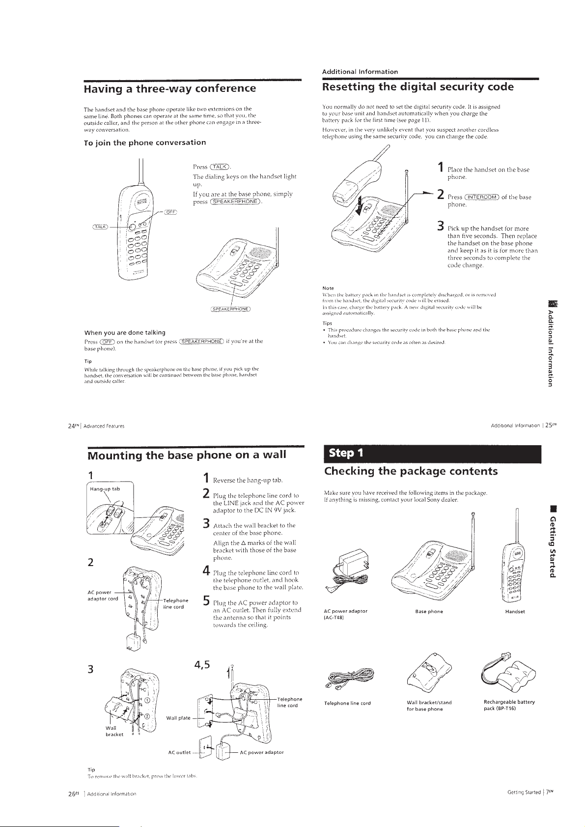
Having a three-way conference ...................................... 7
Resetting the digital security code.................................. 7
Mounting the base phone on a wall ................................ 7
Checking the package contents....................................... 7
2. DISASSEMBLY ......................................................... 8
3. TEST MODE
3-1. Base Unit ......................................................................... 11
3-2. Handset ............................................................................ 11
3-3. Test Mode Execution ...................................................... 12
3-4. Frequency Table for Each Channel................................. 14
4. ELECTRICAL ADJUSTMENTS
4-1. Base Unit Section............................................................ 15
4-2. Handset Section............................................................... 18
Notes on chip component replacement
• Never reuse a disconnected chip component.
• Notice that the minus side of a tantalum capacitor may be damaged by heat.
SAFETY-RELATED COMPONENT WARNING!!
COMPONENTS IDENTIFIED BY MARK ! OR DOTTED LINE
WITH MARK ! ON THE SCHEMATIC DIAGRAMS AND IN
THE PARTS LIST ARE CRITICAL TO SAFE OPERATION.
REPLACE THESE COMPONENTS WITH SONY P AR TS WHOSE
PART NUMBERS APPEAR AS SHOWN IN THIS MANUAL
OR IN SUPPLEMENTS PUBLISHED BY SONY.
ATTENTION AU COMPOSANT AYANT RAPPORT
À LA SÉCURITÉ!
LES COMPOSANTS IDENTIFIÉS P AR UNE MARQ UE ! SUR
LES DIAGRAMMES SCHÉMATIQUES ET LA LISTE DES
PIÈCES SONT CRITIQUES POUR LA SÉCURITÉ DE
FONCTIONNEMENT . NE REMPLACER CES COM- POSANTS
QUE P AR DES PIÈCES SONY DONT LES NUMÉR OS SONT
DONNÉS DANS CE MANUEL OU D ANS LES SUPPLÉMENTS
PUBLIÉS PAR SONY.
5. DIAGRAMS
5-1. Block Diagram – HANDSET Section –........................ 21
5-2. Block Diagram – BASE UNIT Section (1/2) –............. 23
5-3. Block Diagram – BASE UNIT Section (2/2) –............. 25
5-4. Note for Printed Wiring Boards
and Schematic Diagrams ................................................ 27
5-5. Printed Wiring Board – HANDSET Section – .............. 29
5-6. Schematic Diagram – HANDSET Section –................. 31
5-7. Printed Wiring Boards – BASE MAIN Section – ......... 33
5-8. Schematic Diagram – BASE MAIN Section – ............. 35
5-9. Printed Wiring Board – BASE KEY Section – ............. 37
5-10. Schematic Diagram – BASE KEY Section –................ 38
5-11. IC Pin Function Description ........................................... 39
6. EXPLODED VIEWS ................................................ 41
7. ELECTRICAL PARTS LIST ............................... 43
– 2 –
SECTION 1
GENERAL
This section is extracted from
instruction manual.
– 3 –
– 4 –
– 5 –
– 6 –
– 7 –
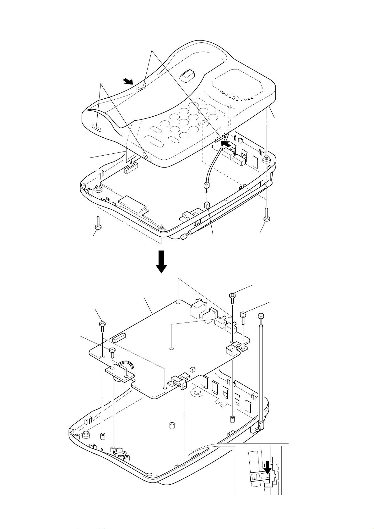
SECTION 2
DISASSEMBLY
Note: Follow the disassembly procedure in the numerical order given.
• HADESET
REAR CABINET
2
two screws
(BTP2.6
1
×
16)
battery case lid
3
two claws
4
Removal the rear cabinet to
direction of the arrow
3
two claws
A
A
.
– 8 –
HAND (MAIN) BOARD
1
screw
(PS2.6
×
16)
1
screw
(BTP2.6
×
8)
3
connector
(J502)
2
HAND MAIN board
– 9 –
)
• BASE UNIT
y
BASE UNIT (UPPER) ASS’Y
2
two claws
4
flat type wire (12core)
(J4)
2
two claws
3
base unit (upper) ass’
BASE (MAIN) BOARD
1
two screws
(BTP2.6
3
two screws
(BTP2.6
×
8)
1
two screws
(BTP2.6
×
8)
×
12)
5
BASE MAIN board
4
connector
(J5)
1
two screws
(BTP2.6
1
three screws
(BTP2.6
2
×
12)
×
8)
screw
(PS3
×
12
– 10 –
4
Remove the knob (VOL) to
the arrow direction.

SECTION 3
TEST MODE
3-1. BASE UNIT
[Setting the Test Mode]
1. First of all, it should be set the [DIALMODE] switch (S2) in
the “TONE” position.
2. Connect the DC power supply to the unit while pressing the
[*] button and [#] button on the B ASE UNIT simultaneously .
Beep tone will be heared when test mode is set up.
[Releasing the Test Mode]
To release the test mode, perform as follows:
• Turn off the power (disconnect and reconnect the AC adapter
plug).
• Set the handset to charge on the base unit (except test mode 15).
• Bell in (except test mode 14).
[Changing the Test Mode No.]
• Press the [INTERCOM] button.
[Changing the Channel]
• Press the [HOLD] button.
Channel will be back to initial channel (CH6), when test mode
No. is changed.
When it is test mode 12 or 13, DTMF will be changed.
CHARGE LED lights for 300 msec every changing of channel
or test mode No.
• Channel rotation
→ CH6 → CH18 → CH1 → CH10 → CH11 → CH25 →
CH2 → CH3 → CH4 → CH5 → CH7 → CH8 →
CH9 → CH12 → CH13 → CH14 → CH15 →
CH16 → CH17 → CH19 → CH20 → CH21 →
CH22 → CH23 → CH24 →
3-2. HANDSET
[Setting the Test Mode]
1. Set [VOL] switch (S501) to the minimum position.
2. While pressing the [*] button and [#] button on the HANDSET simultaneously. Beep tone will be heared when test mode
is set up.
[Releasing the Test Mode]
To release the test mode, perform as follows:
• Press the [TALK] button or [REDIAL/PAUSE] button.
• Turn off the power (disconnect and reconnect battery connec-
tor).
• Set the handset to charge on the base unit (except test mode 10).
[Changing the Test Mode No.]
• Press the each button of the test mode No.
[Changing the Channel]
• Press the [CHANNEL] button.
The channel is back to initial channel (CH6), when test mode No.
is changed.
• Channel rotation
→ CH6 → CH18 → CH1 → CH10 → CH11 → CH25 →
CH2 → CH3 → CH4 → CH5 → CH7 → CH8 →
CH9 → CH12 → CH13 → CH14 → CH15 →
CH16 → CH17 → CH19 → CH20 → CH21 →
CH22 → CH23 → CH24 →
– 11 –

3-3. TEST MODE EXECUTION
Table 3-1. Base Unit Test Mode
PLL IC Hard
control control
STEP
Test Mode Name
1 VCO/TX FREQ. ADJ 6 H H H L L L H L H H H TX/RX VCO Check
2 TX MODE CT PASS 6 L H H L H H H L H H H
3 TX MODE INT PASS 6 L H H L L L H H L L L
4 TX DATA 6 H H H L L L H L H H H CODE Transmitter *1
5 RX ADJ TXB ON 6 H L H L H H H L H H H
6 RX ADJ TXB OFF 6 H L L HHHHLHHH
7 RSSI CHECK 6 L L H L H H H L H H H RSSI check *3
8 RX MODE INT PASS 6 H L H L L L H H L L H INT Receiver (CT → SPK)
9 DATA IN CHECK 6 L L L H L L H L L H H CODE Receiver *2
10 SP PHONE MIC MUTE 6 H H L H H LLLLLH
11 SP PHONE SPK MUTE 6 H H L H H LLLLLL
12 DTMF SINGLE TONE 6 H H L H H L H L L H H
13 DTMF DUAL TONE 6 H H L H H L H L L H H DTMF output (DUAL) *7
14 BELL CHECK 6 H H L H L L H L L L H BELL check *4
15 CHARGE CHECK 6 H H L H L L H L L L H CHG check *5
INITIAL CH
TX MUTE
RX MUTE
TXVCO
TXPWR
CTPAS
RLCONT
SPKPAS
INTPAS
SPKENB
SPKMUTE
MICMUT
Remarks
CT Transmitter
(TEL → CT)
INT Transmitter
(MIC → CT)
RX Sensitivity•DISCRI•
TEL output check
SPEAKERPHON SPK
output (TEL → SPK)
SPEAKERPHON TEL
output (MIC → TEL)
DTMF output
(SINGLE) *6
*1 Continue output TX data as “0000…”. (200Hz)
*2 When locked receiving data is “000…” or “111…” (200,
400Hz), ring a bell tone and CHARGE LED lights.
*3 When P_RSSI is “L”, ring a bell tone and CHARGE LED
lights.
*4 When it detects bell, ring a bell tone and CHARGE LED lights.
*5 When P_CHRGIN is “L” (Charge on), ring a bell tone and
CHARGE LED lights.
*6 When
*7 When
[SPEAKERPHONE] button is pressed, DTMF will be
changed ROW1 → 2 → 3 → 4 → ROW1 → 2 → 3….
[SPEAKERPHONE] button is pressed, DTMF will be
changed 1 → 2 → 3 → 4 → 5 → 6 → 7 → 8 → 9 → 0
→ → # → A → B → C → D → 1 → 2….
DTMF frequency list
ROW1: 696.95 Hz
ROW2: 770.13 Hz
ROW3: 852.27 Hz
ROW4: 940.99 Hz
COL1 : 1209.31 Hz
COL2 : 1335.65 Hz
COL3 : 1476.71 Hz
– 12 –
 Loading...