

Sony PMW-320K, PMW-320L, SPMW-320L Operating Instructions Manual

4198304130
4-198-304-13 (1)
Solid-State Memory
Camcorder
Operating Instructions
Before operating the unit, please read this manual thoroughly
and retain it for future reference.
PMW-320K
PMW-320L
© 2010 Sony Corporation
Printed in Japan
Printed on recycled paper.

WARNING
To reduce the risk of fire or
electric shock, do not
expose this apparatus to
rain or moisture.
To avoid electrical shock,
do not open the cabinet.
Refer servicing to qualified
personnel only.
Important Safety Instructions
• Read these instructions.
• Keep these instructions.
• Heed all warnings.
• Follow all instructions.
• Do not use this apparatus near water.
• Clean only with dry cloth.
• Do not block any ventilation openings.
Install in accordance with the
manufacturer’s instructions.
• Do not install near any heat sources such
as radiators, heat registers, stoves, or
other apparatus (including amplifiers) that
produce heat.
• Do not defeat the safety purpose of the
polarized or grounding-type plug. A
polarized plug has two blades with one
wider than the other. A grounding-type
plug has two blades and a third grounding
prong. The wide blade or the third prong
are provided for your safety. If the
provided plug does not fit into your outlet,
consult an electrician for replacement of
the obsolete outlet.
• Protect the power cord from being walked
on or pinched particularly at plugs,
convenience receptacles, and the point
where they exit from the apparatus.
• Only use attachments/accessories
specified by the manufacturer.
• Use only with the cart, stand, tripod,
bracket, or table specified by the
manufacturer, or sold with the apparatus.
When a cart is used, use caution when
moving the cart/apparatus combination to
avoid injury from tip-over.
• Unplug this apparatus during lightning
storms or when unused for long periods of
time.
• Refer all servicing to qualified service
personnel. Servicing is required when the
apparatus has been damaged in any way,
such as power-supply cord or plug is
damaged, liquid has been spilled or
objects have fallen into the apparatus, the
apparatus has been exposed to rain or
moisture, does not operate normally, or
has been dropped.
WARNING
Excessive sound pressure from earphones
and headphones can cause hearing loss.
In order to use this product safely, avoid
prolonged listening at excessive sound
pressure levels.
For the customers in the U.S.A.
This equipment has been tested and found
to comply with the limits for a Class A digital
device, pursuant to Part 15 of the FCC
Rules. These limits are designed to provide
reasonable protection against harmful
interference when the equipment is operated
in a commercial environment. This
equipment generates, uses, and can radiate
radio frequency energy and, if not installed
and used in accordance with the instruction
manual, may cause harmful interference to
radio communications. Operation of this
equipment in a residential area is likely to
cause harmful interference in which case the
user will be required to correct the
interference at his own expense.
You are cautioned that any changes or
modifications not expressly approved in this
manual could void your authority to operate
this equipment.
All interface cables used to connect
peripherals must be shielded in order to
comply with the limits for a digital device
pursuant to Subpart B of Part 15 of FCC
Rules.
2

This device complies with Part 15 of the FCC
Rules. Operation is subject to the following
two conditions: (1) this device may not cause
harmful interference, and (2) this device
must accept any interference received,
including interference that may cause
undesired operation.
For the customers in Canada
This Class A digital apparatus complies with
Canadian ICES-003.
For the customers in Europe
This product with the CE marking complies
with the EMC Directive issued by the
Commission of the European Community.
Compliance with this directive implies
conformity to the following European
standards:
• EN55103-1: Electromagnetic Interference
(Emission)
• EN55103-2: Electromagnetic
Susceptibility (Immunity)
This product is intended for use in the
following Electromagnetic Environments: E1
(residential), E2 (commercial and light
industrial), E3 (urban outdoors), E4
(controlled EMC environment, ex. TV
studio).
The manufacturer of this product is Sony
Corporation, 1-7-1 Konan, Minato-ku,
Tokyo, 108-0075 Japan.
The Authorized Representative for EMC and
product safety is Sony Deutschland GmbH,
Hedelfinger Strasse 61, 70327 Stuttgart,
Germany. For any service or guarantee
matters please refer to the addresses given
in separate service or guarantee documents.
For the State of California, USA only
Perchlorate Material - special handling may
apply, See
www.dtsc.ca.gov/hazardouswaste/
perchlorate
Perchlorate Material : Lithium battery
contains perchlorate.
For the customers in Taiwan only
AVERTISSEMENT
Afin de réduire les risques
d’incendie ou
d’électrocution, ne pas
exposer cet appareil à la
pluie ou à l’humidité.
Afin d’écarter tout risque
d’électrocution, garder le
coffret fermé. Ne confier
l’entretien de l’appareil
qu’à un personnel qualifié.
AVERTISSEMENT
Une pression acoustique excessive en
provenance des écouteurs ou du casque
peut provoquer une baisse de l’acuité
auditive.
Pour utiliser ce produit en toute sécurité,
évitez l’écoute prolongée à des pressions
sonores excessives.
Pour les clients au Canada
Cet appareil numérique de la classe A est
conforme à la norme NMB-003 du Canada.
Pour les clients en Europe
Ce produit portant la marque CE est
conforme à la Directive sur la compatibilité
électromagnétique (EMC) émise par la
Commission de la Communauté
européenne.
La conformité à cette directive implique la
conformité aux normes européennes
suivantes :
• EN55103-1 : Interférences
électromagnétiques (émission)
3

• EN55103-2 : Sensibilité
électromagnétique (immunité)
Ce produit est prévu pour être utilisé dans
les environnements électromagnétiques
suivants : E1 (résidentiel), E2 (commercial et
industrie légère), E3 (urbain extérieur) et E4
(environnement EMC contrôlé, ex. studio de
télévision).
Le fabricant de ce produit est Sony
Corporation, 1-7-1 Konan, Minato-ku,
Tokyo, 108-0075 Japon.
Le représentant autorisé pour EMC et la
sécurité des produits est Sony Deutschland
GmbH, Hedelfinger Strasse 61, 70327
Stuttgart, Allemagne. Pour toute question
concernant le service ou la garantie, veuillez
consulter les adresses indiquées dans les
documents de service ou de garantie
séparés.
WARNUNG
Um die Gefahr von Bränden
oder elektrischen Schlägen
zu verringern, darf dieses
Gerät nicht Regen oder
Feuchtigkeit ausgesetzt
werden.
Für Kunden in Europa
Dieses Produkt besitzt die CEKennzeichnung und erfüllt die EMVRichtlinie der EG-Kommission.
Angewandte Normen:
• EN55103-1: Elektromagnetische
Verträglichkeit (Störaussendung)
• EN55103-2: Elektromagnetische
Verträglichkeit (Störfestigkeit)
Für die folgenden elektromagnetischen
Umgebungen: E1 (Wohnbereich), E2
(kommerzieller und in beschränktem Maße
industrieller Bereich), E3 (Stadtbereich im
Freien) und E4 (kontrollierter EMV-Bereich,
z.B. Fernsehstudio).
Der Hersteller dieses Produkts ist Sony
Corporation, 1-7-1 Konan, Minato-ku,
Tokyo, 108-0075 Japan.
Der autorisierte Repräsentant für EMV und
Produktsicherheit ist Sony Deutschland
GmbH, Hedelfinger Strasse 61, 70327
Stuttgart, Deutschland. Bei jeglichen
Angelegenheiten in Bezug auf Kundendienst
oder Garantie wenden Sie sich bitte an die in
den separaten Kundendienst- oder
Garantiedokumenten aufgeführten
Anschriften.
Um einen elektrischen
Schlag zu vermeiden, darf
das Gehäuse nicht geöffnet
werden. Überlassen Sie
Wartungsarbeiten stets nur
qualifiziertem
Fachpersonal.
WARNUNG
Zu hoher Schalldruck von Ohrhörern und
Kopfhörern kann Gehörschäden
verursachen.
Um dieses Produkt sicher zu verwenden,
vermeiden Sie längeres Hören bei sehr
hohen Schalldruckpegeln.
4

Table of Contents
Table of Contents
Foreword .................................................................................................... 11
Before Use....................................................................................... 11
Chapter 1 : Overview
Features ...................................................................................................... 12
Using the CD-ROM ................................................................................... 13
Reading the CD-ROM Manuals............................................................... 14
Locations and Functions of Parts and Controls...................................... 14
Power Supply .................................................................................. 14
Accessory Attachments................................................................... 15
Operating and Connectors Section.................................................. 16
Monochrome LCD Panel ................................................................ 26
Auto Focus Lens (Supplied with the PMW-320K)......................... 27
Viewfinder....................................................................................... 28
Viewfinder Screen Display........................................................................ 30
Chapter 2 : Preparations
Preparing a Power Supply ........................................................................ 34
Using a Battery Pack....................................................................... 34
Using AC Power ............................................................................. 35
Attaching the Viewfinder .......................................................................... 36
Attaching the Supplied Viewfinder................................................. 36
Adjusting the Viewfinder Position.................................................. 36
Adjusting the Viewfinder Angle..................................................... 37
Lifting Up the Viewfinder Barrel and Eyepiece ............................. 37
Adjusting the Viewfinder Focus and Screen................................... 38
Using the BKW-401 Viewfinder Rotation Bracket ........................ 38
Attaching a 5-inch Electronic Viewfinder ...................................... 39
Setting the Area of Use .............................................................................. 41
Setting the Date/Time of the Internal Clock ........................................... 42
Mounting and Adjusting the Lens............................................................ 42
Adjusting the Flange Focal Length................................................. 43
Preparing the Audio Input System .......................................................... 44
Connecting a Microphone to the MIC IN Connector...................... 44
Table of Contents
5

Connecting Microphones to the AUDIO IN Connectors................ 45
Attaching a UHF Portable Tuner (for a UHF Wireless Microphone
System) ..................................................................................... 46
Tripod Mounting ....................................................................................... 47
Connecting a Video Light ......................................................................... 48
Using the Shoulder Strap .......................................................................... 48
Adjusting the Shoulder Pad Position....................................................... 49
Chapter 3 : Adjustments and Settings
Setting the Video Format .......................................................................... 50
Changing the Video Format............................................................ 51
Adjusting the Black Balance and the White Balance............................. 51
Adjusting the Black Balance........................................................... 51
Adjusting the White Balance .......................................................... 52
Setting the Electronic Shutter................................................................... 54
Shutter Modes ................................................................................. 54
Selecting the Shutter Mode and Shutter Speed............................... 55
Changing the Reference Value for Automatic Iris Adjustment............ 56
Zooming...................................................................................................... 57
Switching between Zoom Modes.................................................... 57
Using Manual Zoom ....................................................................... 57
Using Servo Zoom .......................................................................... 57
Adjusting the Focus ................................................................................... 58
Adjusting in Full MF Mode ............................................................ 58
Adjusting in MF Mode.................................................................... 58
Adjusting in AF Mode .................................................................... 59
Using Macro Mode ......................................................................... 59
Adjusting the Audio Level ........................................................................ 59
Manually Adjusting the Audio Levels of the Audio Inputs from the
AUDIO IN CH-1/CH-2 Connectors ......................................... 59
Manually Adjusting the Audio Level of the MIC IN Connector .... 60
Recording Audio on Channels 3 and 4 ........................................... 60
Setting the Time Data................................................................................ 62
Setting the Timecode....................................................................... 62
Setting the User Bits........................................................................ 62
Synchronizing the Timecode........................................................... 63
Checking Camcorder Settings and Status Information
(Status Screens).................................................................................... 64
Table of Contents
6

Chapter 4 : Shooting
Handling SxS Memory Cards................................................................... 66
Basic Operations........................................................................................ 70
Advanced Operations ................................................................................ 73
Planning Metadata Operations ................................................................ 79
About SxS Memory Cards .............................................................. 66
Loading and Ejecting SxS Memory Cards...................................... 67
Selecting the SxS Memory Card to Use.......................................... 68
Formatting (Initializing) SxS Memory Cards................................. 68
Checking the Remaining Recording Time...................................... 69
Restoring SxS Memory Cards......................................................... 69
Playing Recorded Clips................................................................... 71
Deleting Recorded Clips ................................................................. 72
Recording Shot Marks..................................................................... 73
Setting OK Marks ........................................................................... 73
Starting to Record from Pre-stored Video
(Picture Cache Function) .......................................................... 73
Recording Time-lapse Video (Interval Rec Function).................... 74
Shooting Stop Motion Animations (Frame Rec Function) ............. 76
Shooting with Slow & Quick Motion ............................................. 77
Framing Shots with the Freeze Mix Function................................. 78
Loading a Planning Metadata File into Camcorder’s Internal
Memory..................................................................................... 80
Defining Clip Names in Planning Metadata ................................... 81
Defining Shot Mark Names in Planning Metadata ......................... 82
Chapter 5 : Clip Operations
Clip Playback ............................................................................................. 83
Thumbnail Screen ........................................................................... 83
Playing Clips................................................................................... 85
Using Thumbnails to Search Inside Clips....................................... 86
Thumbnail Operations.............................................................................. 87
THUMBNAIL Menu Configuration............................................... 87
Basic THUMBNAIL Menu Operations.......................................... 88
Changing the Thumbnail Screen Type............................................ 88
Displaying Clip Properties .............................................................. 89
Adding and Deleting OK Marks (HD Mode Only) ........................ 90
Copying Clips ................................................................................. 90
Deleting Clips.................................................................................. 91
Displaying the Expand Thumbnail Screen...................................... 92
Displaying the Shot Mark Thumbnail Screen (HD Mode Only).... 93
Table of Contents
7

Adding and Deleting Shot Marks (HD Mode Only)....................... 93
Changing Clip Index Pictures (HD Mode Only)............................. 94
Dividing Clips (HD Mode Only) .................................................... 94
Chapter 6 : Menu and Detailed Settings
Setup Menu Organization and Levels...................................................... 95
Setup Menu Organization ............................................................... 95
Setup Menu Levels.......................................................................... 95
Basic Setup Menu Operations .................................................................. 97
Menu List.................................................................................................... 99
OPERATION Menu........................................................................ 99
PAINT Menu................................................................................. 115
MAINTENANCE Menu............................................................... 121
FILE Menu.................................................................................... 134
Assigning Functions to Assignable Switches ......................................... 138
Functions That Can Be Assigned to the ASSIGN. 0 Switch ........ 138
Functions That Can Be Assigned to the ASSIGN. 2 Switch ........ 139
Functions That Can Be Assigned to the ASSIGN. 1 and 3 Switches,
the ASSIGNABLE 4 and 5 Switches, and the COLOR TEMP.
Button...................................................................................... 139
Functions That Can Be Assigned to the RET Button on the Lens 141
Adjusting Picture Characteristics to Match the PMW-EX1R ............ 142
Chapter 7 : Saving and Loading User Setting Data
Saving and Loading Settings................................................................... 143
Saving Setting Data....................................................................... 143
Loading Setting Data..................................................................... 144
Resetting a File after Changing Its Contents................................. 144
Saving and Loading Scene Files ............................................................. 145
Saving Scene Files ........................................................................ 145
Loading Scene Files...................................................................... 145
Saving and Loading Lens Files............................................................... 146
Setting Lens File Data................................................................... 146
Saving Lens Files.......................................................................... 146
Loading Lens Files........................................................................ 147
Loading Lens Files Automatically................................................ 147
Table of Contents
8

Chapter 8 : Connecting External Devices
Connecting External Monitors ............................................................... 148
Operating Clips with a Computer.......................................................... 150
Using the ExpressCard Slot of a Computer .................................. 150
USB Connection with a Computer................................................ 150
Connecting an External Device (i.LINK Connection).......................... 152
Recording the Camera Picture on an External Device.................. 152
Nonlinear Editing.......................................................................... 153
Recording External Input Signals ................................................. 153
Configuring a Shooting and Recording System.................................... 154
Chapter 9 : Maintenance
Testing the Camcorder............................................................................ 155
Maintenance............................................................................................. 155
Cleaning the Viewfinder ............................................................... 155
Note about the Battery Terminal................................................... 155
Operation Warnings................................................................................ 156
Error Indication............................................................................. 156
Warning Indication........................................................................ 157
Appendix
Important Notes on Operation ............................................................... 163
Exchanging the Battery of the Internal Clock...................................... 165
Specifications............................................................................................ 165
General .......................................................................................... 165
Camera Block................................................................................ 166
Audio Block .................................................................................. 166
Display .......................................................................................... 166
Media Block.................................................................................. 167
Inputs/Outputs............................................................................... 167
Lens Block (PMW-320K Only).................................................... 167
Supplied Accessories .................................................................... 168
Recommended Additional Equipment .......................................... 168
Chart of Optional Components and Accessories .................................. 170
About i.LINK ........................................................................................... 171
MPEG-2 Video Patent Portfolio License............................................... 172
About Bitmap Fonts ................................................................................ 172
Table of Contents
9

About OpenSSL ....................................................................................... 173
Index.......................................................................................................... 176
Table of Contents
10

Foreword
Before Use
After purchasing the PMW-320K/320L SolidState Memory Camcorder, before operating, it is
necessary to set the area of use.
(Unless this setting is made, the camcorder will
not operate.)
For details of these settings, see “Setting the Area of
Use” (page 41).
Note
Before attaching/removing optional components or
accessories to/from the PMW-320K/320L (referred to as
“the camcorder”), be sure to turn the power of the
camcorder off.
Foreword
11

Chapter 1 Overview
Chapter1 Overview
Features
The camcorder is a shoulder-mount HD memory
camcorder. It is provided with three
(diagonal 8 mm (
(1920×1080) “Exmor” CMOS image sensors.
1
/2-type bayonet mount
The camcorder is provided with a 1/2-type
bayonet mount (flange focal length 38 mm (
inches), allowing you to use Sony
bayonet mount exchangeable lenses.
11
/32 inches)) full-HD
SxS memory cards as recording media
Using SxS memory cards, the camcorder offers
nonlinear capabilities such as instant random
access and file-based operation.
Light weight, low power consumption
Design features such as CMOS image sensors,
custom video signal processing ICs, and SxS
memory card recording enable fanless operation
and power consumption of 15 W or less. The
camcorder’s light weight (3.2 kg (7 lb 0.88 oz))
and low center of gravity make it easy to carry on
the shoulder while ensuring superior stability.
HD recording using the “MPEG-2 Long
GOP” codec
The camcorder records 1920 × 1080, 1440 ×
1080, and 1280 × 720 HD images using “MPEG2 Long GOP” codec compression. It offers a
choice of bit rates: either 35 Mbps (HQ mode) or
25 Mbps (SP mode).
By utilizing an efficient compression format, the
camcorder records high-quality HD images for
long recording time of approx. 100 minutes at 35
Mbps (HQ mode) or approx. 140 minutes at 25
Mbps (SP mode) on a single 32-GB SxS memory
card.
1
/2-type
1
/2-type
1
/2
Multi-format support
The camcorder supports interlace format
recording (1080/59.94i or 1080/50i), progressive
format recording (1080/29.97P, 1080/23.98P,
720/59.94P, 720/29.97P, 720/23.98P, or 1080/
25P, 720/50P, 720/25P), thus offering the
flexibility needed for worldwide HD recording.
(For 23.98P, native frequency recording is
possible.)
It also supports recording and playback of SD
signals (both NTSC and PAL). The camcorder
has an optional capability to record and play back
SD signals in DVCAM-AVI format, and can
output HD signals down-converted to SD.
A special auto focus lens
The camcorder is provided with the 1/2-type auto
focus lens, which ensures high-quality shooting
in all situations from wide angle to telephoto
(PMW-320K only).
A variety of functions for improved
performance under various shooting
conditions
• Picture Cache function
• Optical ND filters and electrical CC filters
• Hyper gamma
• Slow shutter function
• Frame Recording function
• Time lapse function (interval recording)
• Slow & quick motion function
• Freeze mix function
• Focus magnification function
• Digital extender function
• Image inversion function
• Assignable switches
• 3.5-inch high-resolution color LCD viewfinder
• Remote control
1) When the optional CBK-CE01 50 Pin Interface and
Digital Extender is installed
1)
Wireless LAN support
You can connect this camcorder to a computer
over a wireless LAN (Wi-Fi connection) by
installing the optional CBK-UPG02 Hardware
12
Features

Upgrade Key and connecting the optional CBKWA01 Wi-Fi Adapter to the external device
connector.
A Wi-Fi connection allows you to transfer
planning metadata from a computer to this
camcorder, and to transfer clips and other files
from this camcorder to a computer. You can also
use the Live Logging function to transfer proxy
AV data to a computer as you shoot, for logging
of the video currently being shot.
Inherits unique features of XDCAM EX
series
The camcorder inherits the workflow features of
the XDCAM EX series, including thumbnail
display and metadata management, and improves
them by introducing an improved man-machine
interface.
XDCAM EX web sites
For information about XDCAM EX, visit Sony
professional products web site.
Camcorder system configuration
When you install the optional CBK-CE01 50 Pin
Interface and Di gital Extender, you can mount t he
XDCA-55 HD Camera Adaptor and connect the
XDCU-50 HD Camera Extension Unit to
configure a system for shooting and recording.
When the CBK-CE01 is installed, you can also
connect the HDCA-702 MPEG TS Adaptor
instead of the camera adaptor. This allows you to
convert this camcorder’s HDSDI output to a
MPEG HD transport stream.
Using the CD-ROM
Two CD-ROMs are supplied with the camcorder.
The CD-ROM labeled “Manuals for Solid-State
Memory Camcorder” contains the PDF files of
the Operating Instructions and Supplement for
the camcorder (Japanese, English, French,
German, Italian, Spanish and Chinese).
The supplied CD-ROM (labeled “Utility
Software for Solid-State Memory Camcorder and
Recorder”) cont ains application and device driver
software required to access to SxS memory cards
from a computer and to manage material shot
with the camcorder.
Information about how to install the software is
provided in PDF format.
Note
You must install the SxS device driver on your com puter
if your computer is equipped with an ExpressCard slot
and you want to use it to access SxS memory cards.
Chapter 1 Overview
Using the CD-ROM
13
Chapter 1 Overview
Reading the CD-ROM Manuals
Locations and Functions of Parts and Controls
Preparations
The following program must be installed on your
computer in order to read the documents
contained on the CD-ROM.
Adobe Reader Version 6.0 or higher
Memo
If Adobe Reader is not installed, you can download it
from the following URL:
http://www.adobe.com/
Adobe and Adobe Reader are trademarks of Adobe
Systems Incorporated in the United States and/or other
countries.
To read the documents
Do the following:
1 Insert the CD-ROM in your CD-ROM
drive.
A cover page appears automatically in your
browser.
If it does not appear automatically in the
browser, double-click on the index.htm file
on the CD-ROM.
2 Select and click on the manual that you
wish to read.
This opens the PDF file.
Memo
The files may not be displayed properly, depending on
the version of Adobe Reader. In such a case, install the
latest version you can download from the URL
mentioned in “Preparations” above.
Note
If you have lost or damaged the CD-ROM, you can
purchase a new one to replace it. Contact a Sony service
representative.
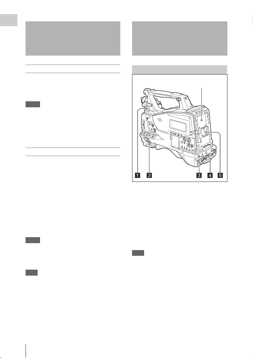
Power Supply
Adaptor connector
(see page 15)
a LIGHT switch
Determines how a video light connected to the
LIGHT connector (see page 16) is turned on and
off.
AUT O: When the POWER switch of the video
light is in the on position, the video light is
turned on automatically while the camcorder
is recording.
MANUAL: You can turn the video light on or off
manually, using its own switch.
Note
When the camcorder is set for recording in Picture Cache
mode, it is not possible to turn on the light before
operation to start recording is carried out (or while data
is being stored in memory).
b POWER switch
Turns the main power supply on and off.
Reading the CD-ROM Manuals / Locations and Functions of Parts and Controls
14
c DC IN (DC power input) connector
(XLR type, 4-pin, male)
To operate the camcorder from an AC power
supply, connect an optional DC power cord to this
terminal and then connect the cord to the DC
output terminal of the BC-L70, BC-L160, or
another battery charger.
d DC OUT 12V (DC power output)
connector (4-pin, female)
Supplies power for an optional WRR-860C/861/
862 UHF Synthesized Diversity Tuner
(maximum 0.5 A).
Note
Do not connect any equipment other than the UHF
synthesized diversity tuner.
e Battery attachment shoe
Attach a BP-L80S Battery Pack. Alternatively,
you can attach an AC-DN2B/DN10 AC Adaptor
to operate the camcorder on AC power supply.
For details, see “Preparing a Power Supply”
(page 34).
For details, see “Attaching a UHF Portable Tuner
(for a UHF Wireless Microphone System)”
(page 46).
Note
For your safety, and to ensure proper operation of the
camcorder, Sony recommends the use of the BP-L80S
Battery Pack.
Adaptor connector
Enables connection of an XDCA-55 HD Camera
Adaptor or an HDCA-702 MPEG TS Adaptor. To
connect an adaptor, remove the cover from the
connector and install the optional CBK-CE01 50
Pin Interface and Digital Extender.
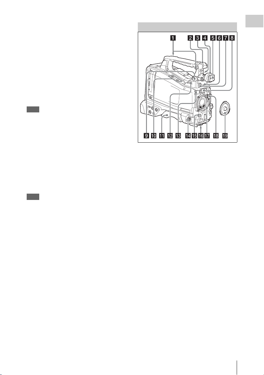
Accessory Attachments
a Shoulder strap fitting
Attach the supplied shoulder strap (see page 48).
b Accessory fitting shoe
Attach an optional accessory such as a video light
(see page 48).
c Viewfinder front-to-back positioning
lever
To adjust the viewfinder position in the front-toback direction, loosen this lever and the LOCK
knob. After adjustment, retighten this lever and
the LOCK knob.
d Viewfinder left-to-right positioning ring
Loosen this ring to adjust the left-to-right position
of the viewfinder (see page 36).
e Viewfinder fitting shoe
Attach the viewfinder.
Chapter 1 Overview
f VF (viewfinder) connector (26-pin,
rectangular)
Connect the cable of the supplied viewfinder.
g VF (viewfinder) connector (20-pin,
round)
Connect the cable of the optional DXF-51, DXFC50W or DXF-20W viewfinder.
For connecting the DXF-51 or DXF-C50W, optional
parts are required. Consult a Sony service
Locations and Functions of Parts and Controls
15
representative for information about connecting the
DXF-51 or DXF-C50W.
Chapter 1 Overview
h Lens mount securing rubber
After locking the lens in position using the lens
locking lever, fit this rubber over the lower of the
two projections. This fixes the lens mount,
preventing it from coming loose.
i Viewfinder front-to-back positioning
knob (LOCK knob)
Loosen this knob to adjust the front-to-back
position of the viewfinder (see page 36).
q Lens mount (special bayonet mount)
Attach the lens.
On the inner side of the lens mount is a 14-pin
connector (two 7-pin connectors) for connecting
the lens.
Consult a Sony service representative for
information about available lenses.
Note
The auto iris function is not available if the mounted lens
has a 7-pin connector for connection to the camera.
The video level indication and the iris position indication
are also disabled.
j Fitting for optional microphone holder
Fit an optional CAC-12 Microphone Holder (see
page 45).
k Shoulder pad
Raise the shoulder pad fixing lever to adjust the
position in the front-to-rear direction. Adjust the
position for maximum convenience when
operating the camcorder on your shoulder (see
page 49).
l LIGHT (video light) connector (2-pin,
female)
A video light with a maximum power
consumption of 50 W, such as the Anton Bauer
Ultralight 2 or equivalent can be connected (see
page 48).
m Lens cable clamp
Clamp a lens cable.
n MIC IN (microphone input) (+48 V)
connector (XLR type, 5-pin, female)
Connect a stereo microphone to this connector.
The power (+48 V) is supplied via this connector.
o LENS connector (12-pin)
Connect a lens cable to this connector.
This connector is not used for a
which is connected by a hot shoe inside the lens
mount.
Note
When connecting or disconnecting the lens cable to this
connector, power off the camcorder first.
1
/2-inch lens
r Lens locking lever
After inserting the lens in the lens mount, rotate
the lens mount ring with this lever to lock the lens
in position.
After locking the lens, be sure to use the lens
mount securing rubber to prevent the lens from
becoming detached.
s Lens mount cap
Remove by pushing up the lens locking lever.
When no lens is mounted, keep this cap fitted for
protection from dust.
Operating and Connectors Section
Front
p Tripod mount
When using the camcorder on a tripod, attach the
tripod adaptor (optional).
Locations and Functions of Parts and Controls
16
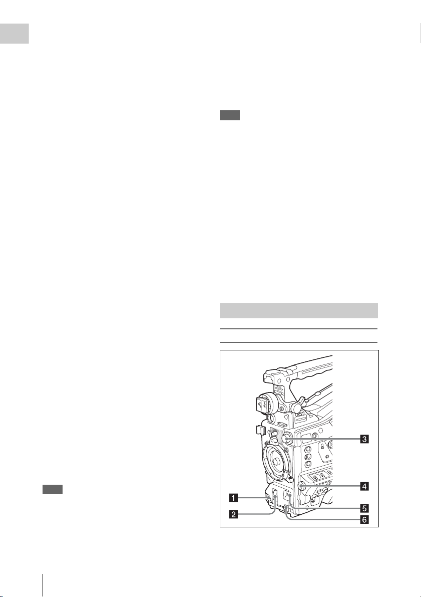
a REC START (recording start) button
Press to start recording. Press it again to stop
recording. The effect is the same as that of the
REC button on the lens.
b SHUTTER selector
Set to ON to use the electronic shutter. Push to
SELECT to switch the shutter speed or shutter
mode setting. When this switch is operated, the
new setting appears on the viewfinder screen for
about three seconds.
For details, see “Setting the Electronic Shutter”
(page 54).
c FILTER selector
Switches between four ND filters built into this
camcorder.
When this selector is used, the new setting
appears on the viewfinder screen for about three
seconds.
FILTER selector
setting
1 CLEAR
2
3
4
ND filter
1
/4 ND (attenuates light to
approximately
1
/16 ND (attenuates light to
approximately
1
/64 ND (attenuates light to
approximately
1
/4)
1
/16)
1
/64)
You can change a MAINTENANCE menu
setting so that different white balance settings can
be stored for different FILTER selector positions.
This allows you to automatically obtain optimum
white balance for the current shooting conditions
in linkage with the filter selection.
For details, see “Adjusting the White Balance”
(page 52).
automatic white balance adjustment function
does not operate.
BLACK: Adjust the black set and black balance
automatically.
You can use the AUTO W/B BAL switch even
when the ATW (Auto Tracing White Balance)
function is operating.
If you push the switch to the WHITE side once
more during the automatic white balance
adjustment, the adjustment is cancelled and the
white balance setting returns to the original
setting.
If you push the switch to the BLACK side once
more during the automatic black balance
adjustment, the adjustment is cancelled and the
black balance setting returns to the original
setting.
f MIC (microphone) LEVEL control
Adjusts the input level of audio channels 1, 2, 3
and 4 (see page 59).
Right side (near the front)
Chapter 1 Overview
d MENU knob
Changes the item selection or a setting within the
menu (see page 97).
e AUTO W/B BAL (automatic white/
black balance adjustment) switch
Activates the automatic white/black balance
adjustment functions.
WHITE: Adjust the w hite balance au tomatically.
If the WHITE BAL switch (see page 19) is
set to A or B, the white balance setting is
stored in the corresponding memory. If the
WHITE BAL switch is set to PRST, the
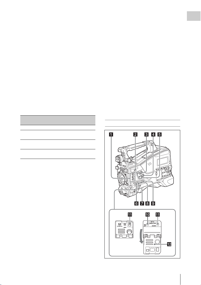
a ASSIGN. (assignable) 1/2/3 switches
Locations and Functions of Parts and Controls
17

You can assign the desired functions to these
switches on OPERATION >Assignable SW in
Chapter 1 Overview
the setup menu (see page 138).
EZ Mode is assigned to the ASSIGN. 1 switch,
and Off is assigned to the ASSIGN. 2/3 switches
as the factory default setting.
The ASSIGN.1/3 switches are provided with an
indicator to show whether a function is assigned
to the switch (ON) or not (OFF).
b COLOR TEMP. (color temperature)
button
Press to light the button and change the color
temperature for shooting (factory default setting).
You can use this as an assignable switch (see
page 138).
c ALARM (alarm tone volume
adjustment) knob
Controls the volume of the warning tone that is
output via the built-in speaker or optional
earphones. When the knob is turned to the
minimum position, no sound can be heard.
However, if MAINTENANCE >Audio >Min
Alarm Volume in the setup menu is set to [Set],
the alarm tone is audible even when this volume
control is at the minimum position.
ALARM
Minimum Maximum
d MONITOR (monitor volume
adjustment) knob
Controls the volume of the sound other than the
warning ton e that is output via t he built-in speaker
or earphones. When the knob is turned to the
minimum position, no sound can be heard.
e MONITOR (audio monitor selection)
switches
By means of combinations of the two switches,
you can select audio that you want to hear through
the built-in speaker or earphones.
Position of down-side switch: CH-1/2
Position of up-side
switch
CH-1/CH-3 Channel 1 audio
MIX Channels 1 and 2 mixed
Audio output
audio (stereo)
a)
Position of up-side
switch
CH-2/CH-4 Channel 2 audio
Audio output
Position of down-side switch: CH-3/4
Position of up-side
switch
CH-1/CH-3 Channel 3 audio
MIX Channels 3 and 4 mixed
CH-2/CH-4 Channel 4 audio
a) By connecting stereo headphones to the EARPHONE
jack, you can hear the audio in stereo. (Under
MAINTENANCE >Audio in the setup menu,
Headphone Out must be set to STEREO.)
Audio output
audio (stereo)
a)
f ASSIGN. (assignable) 0 switch
You can assign the desired function to this switch
on OPERATION >Assignable SW in the setup
menu (see page 139).
Off is assigned to this switch when the camcorder
is shipped from the factory.
This is a momentary type switch. Each press of
the switch turns the function assigned to this
switch on or off.
g GAIN selector
Switches the gain of the video amplifier to match
the lighting conditions duri ng shooting. The gains
corresponding to the L, M, and H settings can be
selected on OPERATION >Gain Switch in the
setup menu (see page 107). (The factory settings
are L=0 dB, M=6 dB, and H=12 dB.)
When this switch is adjusted, the new setting
appears on the viewfinder screen for about three
seconds.
h OUTPUT/DCC (output signal/dynamic
contrast control) switch
Switches the video signal output from the camera
module, between the following two.
BARS: Output the color bar signal.
CAM: Output the video signal being shot. When
this is selected, you can switch DCC
1)
on and
off.
1) DCC (Dynamic Contrast Control): Against a very
bright background with the iris opening adjusted to the
subject, objects in the background will be lost in the
glare. The DCC function will suppress the high
intensity and restore much of the lost detail and is
particularly effective in the following cases.
• Shooting people in the shade on a sunny day
Locations and Functions of Parts and Controls
18

• Shooting a subject indoors, against a background
through a window
• Any high contrast scene
i WHITE BAL (white balance memory)
switch
Controls adjustment of the white balance.
PRST: Adjust the color temperature to the preset
value (the factory default setting: 3200K).
Use this setting when you have no time to
adjust the white balance.
A or B: Recall the white balance adjustment
settings already stored in A or B. Push the
AUTO W/B BAL switch (see page 17) on
the WHITE side, to automatically adjust the
white balance, and save the adjustment
settings in memory A or memory B.
1)
B (ATW
): When this switch is set to B and
OPERATION >White Setting >White
Switch<B> is set to [ATW] in the setup
menu, ATW is activated.
You can use the AUTO W/B BAL switch
even when ATW is in use.
When this switch is adjusted, the new setting
appears on the viewfinder screen for about three
seconds.
1) ATW (Auto Tracing White Balance): The white
balance of the picture being shot is adjusted
automatically for varying lighting conditions.
j MENU ON/OFF switch
To use this switch, open the cover.
This switch is used to display the menu on the
viewfinder screen or the test signal screen. Each
time the switch is pushed down, the menu screen
is turned on and off.
The function of this switch is the same as that of
the MENU button in the thumbnail screen
operations section.
k STATUS ON/SEL/OFF (menu display
on/page selection/display off) switch
MENU CANCEL/PRST (preset) /
ESCAPE switch
When the menu is not displayed, this switch
functions as the STATUS ON/SEL/OFF switch.
When the menu is displayed, the switch functions
as the MENU CANCEL/PRST/ESCAPE switch.
(To use the MENU CANCEL/PRST/ESCAPE
switch, open the cover.)
Use the STATUS ON/SEL/OFF switch in the
following way.
ON/SEL: Each time this switch is pushed
upward, a window to confirm the menu
settings and status of the camcorder appears
on the viewfinder screen (see page 64). The
window consists of five pages, which are
switched each time the switch is pushed
upward. Each page is displayed for about 10
seconds.
OFF: To clear the page immediately after
display, push this switch down to the OFF
position.
Use the MENU CANCEL/PRST/ESCAPE in the
following way.
CANCEL/PRST: Pushing this switch up to this
position after a setting is changed in the setup
menu displays the message to confirm
whether the previous settings are cancelled.
Pushing this switch up to this position again
cancels the previous settings.
Pushing this switch up to this position before
a setting is changed in the setup menu or after
a setting change is cancelled in the setup
menu displays the message to confirm
whether the setting is reset to the initial
value.
Pushing this switch up to this position again
resets the settings to the initial value.
ESCAPE: Use this switch when the menu page,
which has a hierarchical structure, is opened.
Each time the switch is pushed to this
position, the page returns to one stage higher
in the hierarchy.
l Cover
Open this cover to use the MENU ON/OFF
switch or the MENU CANCEL/PRST/ESCAPE
switch.
Chapter 1 Overview
Locations and Functions of Parts and Controls
19
Right side (near the rear)
Chapter 1 Overview
a Built-in speaker
The speaker can be used to monitor E-E1) sound
during recording, and playback sound during
playback. The speaker also sounds alarms to
reinforce visual warnings (see page 156).
If you connect earphones to the EARPHONE
jack, the speaker output is suppressed
automatically.
1) E-E: Abbreviation of “Electric-to-Electric”. In E-E
mode, video and audio signals input to the camcorder
are output after passing through internal electric
circuits only. This can be used to check input signals.
b Monochrome LCD panel
Displays remaining battery capacity, remaining
media capacity, audio levels, time data, and so on
(see page 26).
c WARNING indicator
Lights up or flashes when an abnormality occurs
(see page 156).
d ACCESS lamp
Lights up in blue when data is written to or read
from the recording media.
e Protection cover of the audio control
section
Open to access the audio control section (see
page 22).
f Protection cover of the thumbnail
screen operations section
Open to access the thumbnail screen operations
section (see page 22).
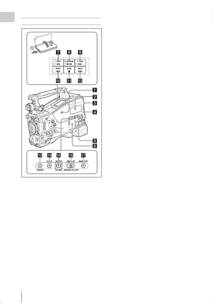
g F REV (fast reverse) button and
indicator
This plays back at high speed in the reverse
direction. The playback speed changes in the
order ×4 t ×15 t ×24 with each press of the
button. The indicator lights during high-speed
playback in the reverse direction.
h PLAY/PAUSE button and indicator
Press this button to view play back video images
using the viewfinder screen. The indicator lights
during playback.
Press this button again during playback to pause,
outputting a still image. At this time the indicator
flashes at a rate of once per second.
Pressing the F REV or F FWD button during
playback or pause starts high speed playback in
the forward or reverse direction.
i F FWD (fast forward) button and
indicator
This plays back at high speed in the forward
direction. The playback speed changes in the
order ×4 t ×15 t ×24 with each press of the
button. The indicator lights during high-speed
playback in the forward direction.
j PREV button
This jumps to the first frame of the current clip.
If you press this together with the F REV button,
the jump is to the first frame of the first recorded
clip on the recording media.
If you press this button twice in rapid succession,
the jump is to the first frame of the last preceding
Locations and Functions of Parts and Controls
20

clip (or the first frame of the current clip when no
preceding clips exist).
k STOP button
Press this button to stop playback.
l NEXT button
This jumps to the first frame of the next clip.
If you press this together with the F FWD button,
the jump is to the first frame of the last recorded
clip on the recording media.
m EXPAND (expand function) button
If you press this button when the thumbnail
screen is displayed, the duration of the selected
clip is divided into fractions, and the first frame of
each of the divisions is shown in a further
thumbnail display (expand function). For an HD
recorded MP4 clip, its duration is divided into 12.
If an SD recorded AVI clip comprises multiple
files, the divisions are displayed for the individual
files.
For MP4 clips, each time you press this button the
division is repeated. Hold down the SHIFT button
and press this button to step back through the
division process.
n HOLD (display hold) button
Pressing this button instantly freezes the time data
displayed in the monochrome LCD panel. (The
timecode generator continues running.) Pressing
this button again releases the hold.
For details of the counter display, see page 26.
o RESET/RETURN button
Resets the value shown in the time counter
display in the monochrome LCD panel.
According to the settings of the PRESET/
REGEN/CLOCK switch (see page 22) and the
F-RUN/SET/R-RUN switch (see page 22), this
button resets the display as follows.
Settings of switches To r eset
DISPLAY switch:
COUNTER
DISPLAY switch:
TC
PRESET/REGEN/
CLOCK switch:
PRESET
F-RUN/SET/R-RUN
switch: SET
Counter to 0:00:00:00
Timecode to 00:00:00:00
Settings of switches To reset
DISPLAY switch:
U-BIT
PRESET/REGEN/
CLOCK switch:
PRESET
F-RUN/SET/R-RUN
switch: SET
a) Of the timecode bits for every frame recorded on the
media, those bits which can be used to record useful
information for the user such as scene number,
shooting place, etc.
For details, see “Setting the Time Data” (page 62).
User bits data
00
a)
to 00 00 00
This button returns to the previous screen when
pressed during thumbnail screen display, expand
thumbnail screen display, or shot mark thumbnail
screen display.
p DISPLAY switch
This cycles the data displayed in the time counter
display in the monochrome LCD panel through
the sequence COUNTER, TC, and U-BIT (see
page 26).
COUNTER: Display the elapsed recording/
playback time (hours, minutes, seconds,
frames).
TC: Display timecode.
U-BIT: Display user bits data.
q BACKLIGHT button
Turns the backlight of the monochrome LCD on
and off. The backlight of the monochrome LCD
panel will be turned on when the camcorder is
powered on for the first time after shipped from
the factory.
Chapter 1 Overview
Locations and Functions of Parts and Controls
21

Thumbnail screen operations section and audio
control section
Chapter 1 Overview
a THUMBNAIL indicator
This lights when thumbnail screen is displayed.
b THUMBNAIL button
Press this button to display the thumbnail screen
(see page 83) and to carry out a thumbnail
operation.
Press once more to return to the original display.
c SET (set) button and arrow buttons
Use these buttons to make timecode and user bit
settings, and for thumbnail screen operations (see
page 88).
When the menu is displayed, press this button to
select an item or to confirm the setting change.
d MENU button
Each press of this button turns the setup menu
display on and off.
The function of this button is the same as that of
the MENU ON/OFF switch.
e F-RUN/SET/R-RUN (free run/set/
recording run) switch
Selects the operating mode of the internal
timecode generator. The operating mode is set as
explained below, depending on the position of the
switch.
F-RUN: Timecode keeps advancing, regardless
of whether the camcorder is recording. Use
this setting when synch ronizing the timecode
with external timecode.
SET: Sets the timecode or user bits.
R-RUN: Timecode advances only during
recording. Use this setting to have a
consecutive timecode on the recording
media.
For details, see “Setting the Timecode” (page 62)
and “Setting the User Bits” (page 62).
f LEVEL CH1/CH2/CH3/CH4 (audio
channel 1/2/3/4 recording level) knobs
Adjust the audio levels t o be recorded on channels
1, 2, 3, and 4 when the AUDIO SELECT CH1/
CH2 and AUDIO SELECT CH 3-4 switches are
set to MANUAL.
g AUDIO SELECT CH 3-4 (audio
channel 3/4 adjustment method
selection) switch
Select the audio level adjustment method for each
of audio channels 3 and 4.
AUT O: Automatic adjustment
MANUAL: Manual adjustment
h ESSENCE MARK button
By pressing this button when the thumbnail
display of a clip is on the screen, you can view the
following thumbnail display of the shot-marked
frames of that clip, depending on the item
selected in a list displayed on the screen.
All: Thumbnail display of all frames marked with
essence marks.
Shot Mark1: Thumbnail display of the frames
marked with Shot Mark 1
Shot Mark2: Thumbnail display of the frames
marked with Shot Mark 2
You can also select Shot Mark 0 and Shot Mark 3
to Shot Mark 9.
If you have recorded clips by using planning
metadata that defined names for Shot Mark 0 to
Shot Mark 9, the defined names are displayed
instead of the above item names in the list.
i SHIFT button
Use this in combination with other buttons.
j PRESET/REGEN (regeneration)/
CLOCK switch
Selects the type of timecode to record.
PRESET: Record new timecode on the media.
REGEN: Record timecode continuous with the
existing timecode recorded on the media.
Regardless of the setting of the F-RUN/SET/
R-RUN switch, the camcorder operates in R-
RUN mode.
CLOCK: Record timecode synchronized to the
internal clock. Regardless of the setting of
the F-RUN/SET/R-RUN switch, the
camcorder operates in F-RUN mode.
Locations and Functions of Parts and Controls
22
k AUDIO SELECT CH1/CH2 (audio
channel 1/2 adjustment method
selection) switches
Select the audio level adjustment method for each
of audio channels 1 and 2.
AUTO : Automatic adjustment
MANUAL: Manual adjustment
l AUDIO IN CH1/CH2/CH3/CH4 (audio
channel 1/2/3/4 input selection) switches
Select the audio input signals to be recorded on
audio channels 1, 2, 3 and 4.
FRONT: Audio input signals from the
microphone connected to the MIC IN
connector
REAR: Audio input signals from an audio device
connected to the AUDIO IN CH-1/CH-2
connectors
WIRELESS: Audio input signals from the UHF
portable tuner if it is installed
Left side and upper section
Chapter 1 Overview
HDMI
GENLOCK
IN
TC IN
VIDEO
OUT
TC
OUT
a ASSIGNABLE 4/5 switches
You can assign the desired functions to these
switches on OPERATION >Assignable SW in
the setup menu (see page 139).
Off is assigned to these switches when the
camcorder is shipped from the factory.
Locations and Functions of Parts and Controls
23

b PC connector
Used to put this camcorder into USB connection
Chapter 1 Overview
mode and use it as an external storage device for
a computer. When a computer without
ExpressCard slot is connected to this connector,
every memory card inserted in the camcorder is
recognized as a drive for that computer.
c External device connector
Connect an optional CBK-WA01 Wi-Fi Adapter.
Connecting a CBK-WA01 allows Wi-Fi
connection (wireless LAN connection) between
the camcorder and a computer.
Notes
• When you connect a CBK-WA01, install the optional
CBK-UPG02 Hardware Upgrade Key.
• Use this connector only for connecting a CBK-WA01.
Do not connect and use a USB hub or similar products.
For details on how to use the CBK-WA01, refer to the
Supplement supplied in the CD-ROM (labeled
“Manuals for Solid-State Memory Camcorder”).
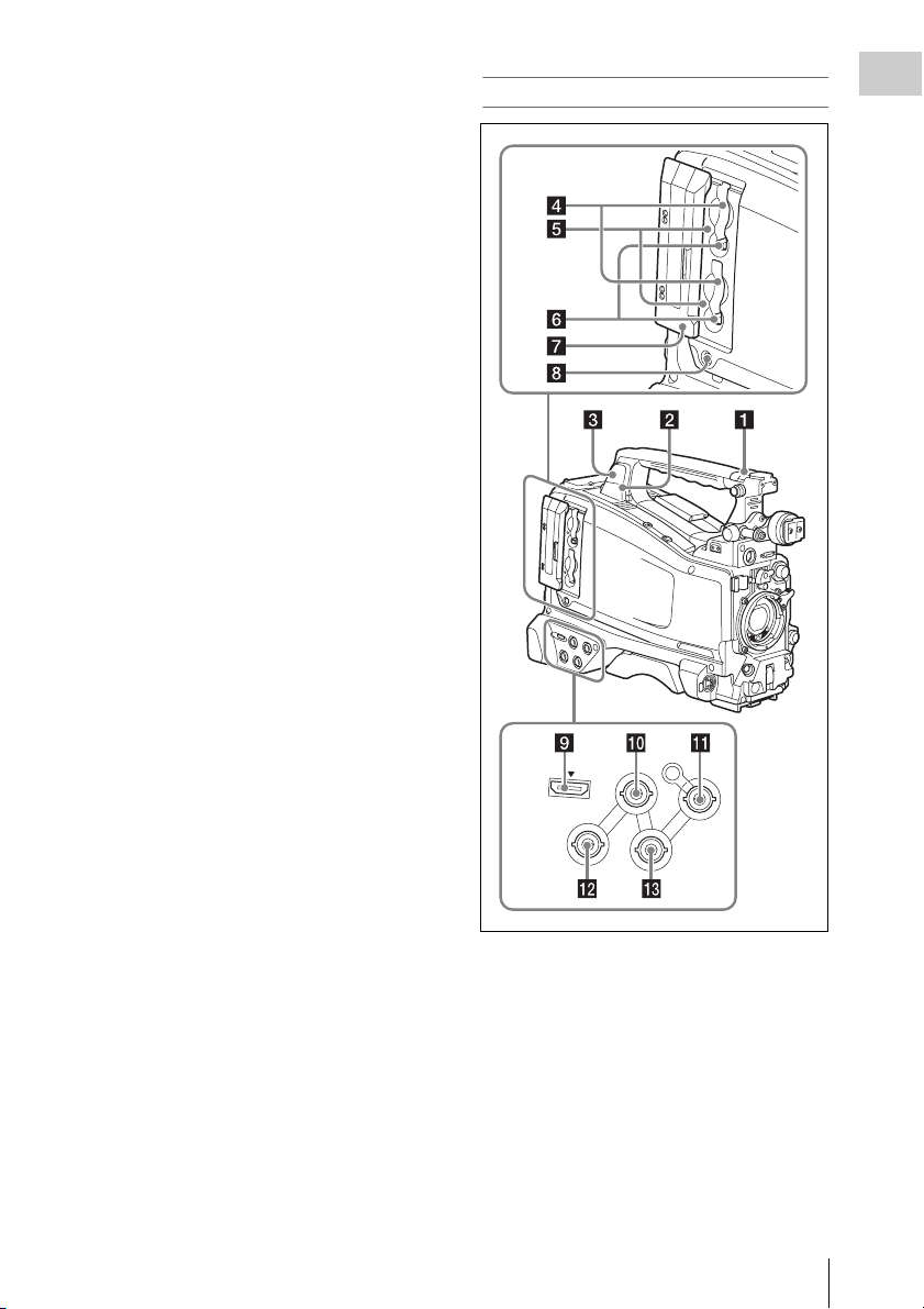
d SxS memory card slots
These two slots (A and B) can receive SxS
memory cards or other recording media (see
page 67).
e ACCESS lamps
Indicate the state of slots A and B (see page 67).
You can check whether the lamps are lit even
when the slot cover is closed.
f EJECT buttons
To remove the recording media from the slot,
press the EJECT button to release the lock, then
press the button once more. This makes the media
come out of the slot partially (see page 68).
g Slot cover
Slide to the left and right to open and close.
h SLOT SELECT (SxS memory card
select) button
When SxS memory cards are loaded in both card
slots A and B, press this button to select the card
you want to use (see page 68).
i HDMI1) output connector
Outputs HDMI signals for video monitoring.
When a video monitor provided with an HDMI
signal input connector is connected to this
connector, you can monitor picture being shot
(camera picture) or playback picture.
1) The terms HDMI and HDMI High-Definition
Multimedia Interface, and the HDMI Logo are
trademarks or registered trademarks of HDMI
Licensing LLC in the United States and other
countries.
j GENLOCK IN (genlock signal input)
connector (BNC type)
This connector inputs a reference signal when the
camcorder is to be genlocked or when timecode is
to be synchronized with external equipment.
Available reference signals vary de pending on the
current system frequency as shown in the
following table.
System frequency Available reference signals
1080/59.94i 1080/59.94i, 480/59.94i
1080/29.97P 1080/59.94i, 480/59.94i
1080/23.98P (PsF
output)
1080/23.98P
(Pulldown output)
720/59.94P 1080/59.94i, 720/59.94P,
720/29.97P 1080/59.94i, 720/59.94P,
720/23.98P 1080/59.94i, 720/59.94P,
480/59.94i 1080/59.94i, 480/59.94i
480/29.97P 1080/59.94i, 480/59.94i
1080/50i 1080/50i, 576/50i
1080/25P 1080/50i, 576/50i
720/50P 1080/50i, 720/50P, 576/50i
720/25P 1080/50i, 720/50P, 576/50i
576/50i 1080/50i, 576/50i
576/25P 1080/50i, 576/50i
1080/23.98PsF, 480/59.94i
1080/59.94i, 480/59.94i
480/59.94i
480/59.94i
480/59.94i
(Genlock for the camera module supports
horizontal sync signals only.) Use
MAINTENANCE >GENLOCK in the setup
menu to adjust the genlock H-phase (phase of
horizontal sync signal).
k TC IN (timecode input) connector
(BNC type)
To apply an external lock to the timecode of the
camcorder, input the reference timecode.
For details, see “Setting the Timecode” (page 62).
Locations and Functions of Parts and Controls
24
l VIDEO OUT connector (BNC type)
Outputs video signals for monitoring. The output
signals can be selected either composite video or
HD-Y depending on the setting of OPERATION
>Input/Output >Output&i.LINK in the setup
menu.
m TC OUT (timecode output) connector
(BNC type)
To lock the timecode of an external VTR to the
timecode of this camcorder, connect this
connector to the external VTR’s timecode input
connector.
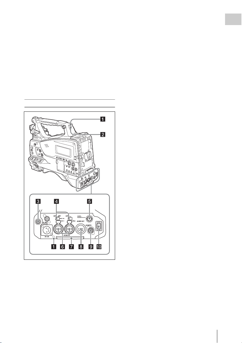
b TALLY switch
Set to ON to activate the TALLY indicator
function.
c EARPHONE jack (stereo, minijack)
You can monitor the E-E sound during recording
and playback sound during playback. When an
alarm is indicated, you can hear the alarm sound
through the earphone. Plugging an earphone into
the jack automatically cuts off the built-in
speaker.
You can select monaural or stereo on
MAINTENANCE >Audio in the setup menu.
Chapter 1 Overview
Rear
a TALLY (back tally) indicators (red)
Light up during recording. They will not light if
the TALLY switch is set to OFF. These indicators
also flash to indicate warnings (see page 20). The
tally indicator on the front of the viewfinder and
the REC indication on the viewfinder screen light
or flash in the same manner.
For details, see “Operation Warnings” (page 156).
d AUDIO IN selectors
Select the audio source you connect to the
AUDIO IN CH-1/CH-2 connectors.
LINE: When connecting a stereo amplifier or
other external audio signal source
MIC: When connecting a microphone that does
not require 48 V power supply
+48V: When connecting a microphone that
requires 48 V power supply
e HD/SD SDI OUT connector (BNC type)
Outputs an HDSDI or SDSDI signal (with
embedded audio). The output from this connector
can be turned on or off by OPERATION >Input/
Output >SDI Output in the setup menu.
f AUDIO IN CH-1/CH-2 (audio channel
1 and channel 2 input) connectors (XLR
type, 3-pin, female)
These are audio input connectors for channels 1
and 2 to which you can connect audio equipment
or a microphone.
g Bottom cover
This is provided for protecting the cables
connected to the connectors on the rear panel.
By loosening the screws which retain the cover to
the bottom of the camcorder, you can adjust the
position of the cover depending on the size and
shape of the microphone or audio cable plugs.
After adjusting the position, tighten the screws to
secure the cover.
Locations and Functions of Parts and Controls
25
h AUDIO OUT connector (XLR type, 5-
Chapter 1 Overview
pin, male)
Outputs the audio signals recorded on audio
channels 1 and 2 or audio channels 3 and 4. The
audio signals are selected by the MONITOR
switch.
When the HOLD button is pressed to hold the
timecode value, the timecode is displayed in the
format shown below. When the HOLD button is
pressed again to release the hold, the timecode is
displayed in the normal format.
i REMOTE connector (8-pin)
Connect a remote control unit, which makes it
possible to control the camcorder remotely.
Note
Before connecting/disconnecting the Remote Control
Unit to/from the camcorder, be sure to turn off the
camcorder POWER switch.
j i.LINK (HDV/DV) connector (6-pin,
IEEE1394 compliant, S400)
To input and output HDV/DV streams, connect to
an HDV/DV device.
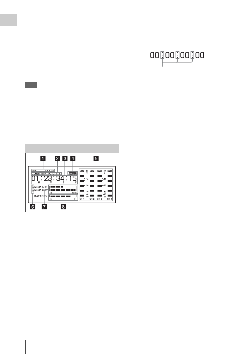
Monochrome LCD Panel
a Timecode status
NDF: Appears when non-drop-frame timecode is
selected.
EXT-LK: Appears when the internal timecode
generator is locked to an external signal input
to the TC IN (timecode input) connector.
The three dots indicates that timecode is
displayed in the hold mode.
d HOLD indication
Appears when the timecode generator output is
displayed in the hold mode.
e Audio level indicators
Indicate the audio recording or playback levels of
channels 1 to 4.
f Lock icon
Appears when the recording media is writeprotected.
g Remaining media capacity indicator
Shows bar segments indicating the remaining
capacity of recording media in the slots.
h Remaining battery capacity indicator
Shows bar segments indicating the remaining
battery capacity.
b Counter display mode
Shows the type of information selected by the
DISPLAY switch to be displayed in the time
counter display.
COUNTER: Counter values
TC: Timecode
U-BIT: User bits data
c Time counter display
Switches displays of time counter values,
timecode, and user bits data, depending on the
position of the DISPLAY switch.
Locations and Functions of Parts and Controls
26

Auto Focus Lens (Supplied with the PMW-320K)
a PUSH AF (auto focus) button
When the focus adjustment is in the manual
mode, by pressing this b utton you can use the auto
focus for an instantaneous adjustment to the
subject.
When the button is pressed, the auto focus
operates until the image is in focus, then
disengages.
Even when the FOCUS switch is set to A (auto),
by pressing this button, you can restart the auto
focus.
b FOCUS switch
A (auto): The auto focus function is constantly
active. Even with the switch in the A
position, you can manually adjust the focus
by operating the focus ring.
M (manual): The manual mode allows focusing
adjustment with the focus ring.
In manual mode, auto focus adjustment is also
possible, by pressing the PUSH AF button.
c MACRO switch
When this switch is in the ON position, the macro
mode is enabled, allowing focusing over the
whole range (5 cm
range (from 5 cm
lens).
This operation is independent of whether the
focus adjustment mode is auto or manual.
In the macro range, the auto focusing speed is
lower.
1) At the wide-angle setting
1)
to ∞) including the macro
1)
to 90 cm from the front of the
d Iris ring
For manual iris adjustment, set the IRIS switch to
the M (manual) position, then turn this ring.
e Zoom ring
For manual zoom adjustment, set the ZOOM
switch to the MANUAL position, then turn this
ring.
f Focus ring
Turn this ring to adjust the focus.
This ring can be turned endlessly in both
directions. The faster you turn, the faster the
focusing mechanism operates, to minimize the
amount of turning required for focusing.
When you slide the focus ring back (toward the
camcorder), the focus mode becomes Full MF
mode (see page 58).
g Flange focal length adjustment button
Press this to adjust the flange focal length (the
distance from the lens mounting flange plane to
the focusing plane) (see page 43).
h Zoom control connector (8-pin)
Connecting an optional zoom servo controller
allows remote control of zooming.
i ZOOM switch
SERVO: Motorized zoom. Operate the zoom
with the power zoom lever.
MANU. (manual): Manual zoom. Operate the
zoom with the zoom ring.
Chapter 1 Overview
Locations and Functions of Parts and Controls
27
j PUSH AUTO button
When the IRIS switch is in the M position for
Chapter 1 Overview
manual adjustment, press this button for an
instantaneous auto adjustment.
The iris is automatically adjusted while the button
is held down.
k IRIS switch
A (auto): The iris is adjusted automatically.
M (manual): Adjust the iris with the iris ring.
seconds recorded appear on the viewfinder screen
(recording review) (see page 71).
Pressing this button (single click) during
recording or playback records a Shot Mark 1
mark, and double-clicking records a Shot Mark 2
mark (see page 73).
n VTR button
Use this to start and stop recording. Press once to
start recording, then press once more to stop.
l Power zoom lever
This is enabled when the ZOOM switch is in the
SERVO position. Press the W end for wide-angle
and the T end for telephoto.
Press the lever harder for a faster zoom action.
Notes on auto focus
• In the following cases, it may be difficult to
focus on the subject. If this does happen, use
manual focusing.
- If the subject has no contrast
- If the subject is moving rapidly
- When shooting point light sources, under
street lighting or at night
- When there are very bright objects close to the
subject
- When shooting through a glass window
• If there are a number of objects within the
screen at close and far range, the focus may not
be on the intended subject. In this case, with the
subject on which you want to focus in the center
of the screen, press the PUSH AF button.
• After focusing with the PUSH AF button, if yo u
operate the zoom or adjust the iris, the depth of
field may become shallower, losing crisp focus.
In such cases, press the PUSH AF button once
more.
• If you focus at wide-angle then zoom to
telephoto, the subject may no longer be in focus.
• It may take time until the image is in focus
while using the slow shutter mode.
Note on zoom speed
Depending on the shooting distance, the zoom
speed may fall as the lens approaches the
telephoto end.
Viewfinder
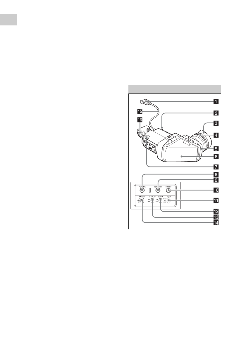
a Plug
Connect to the VF connector (26-pin) on the
camcorder.
b Stopper
Prevents the viewfinder from coming off the
camcorder when it is slid from side to side.
c Eyecup
m RET (return video) button
You can use this as an assignable switch (see
page 141).
Use this to check the video when Lens RET is
assigned to this button (factory default setting). If
you press this during recording pause, the last few
Locations and Functions of Parts and Controls
28
d Diopter adjustment ring
Allows for optimal focus adjustment.
e Eyepiece
You can raise this up when required by the
situation.

f Viewfinder barrel
You can raise this up or rotate when required by
the situation.
g Tally indicator
Lights up when recording is started by a press of
the REC START button on this camcorder, the
VTR button on the lens, or the VTR button on the
remote control unit.
When an abnormality occurs, the tally indicator
flashes to indicate a warning.
h PEAKING control
Turning this control clockwise adjusts the picture
sharpness, and makes focusing easier. This
control has no effect on the output signals of the
camcorder.
i CONTRAST control
Adjusts the contrast of the screen. This control
has no effect on the output signals of the
camcorder.
j BRIGHT control
Adjusts the brightness of the screen. This control
has no effect on the output signals of the
camcorder.
k TALLY switch
Controls the tally indicator located on the front of
the viewfinder.
HIGH: The tally indicator brightness is set to
high.
OFF: The tally indicator is disabled.
LOW: The tally indicator brightness is set to low.
L/R: Reverse the image horizontally.
OFF: Do not reverse the image.
B/T: Reverse the image vertically.
o Viewfinder cable
p Microphone holder
Chapter 1 Overview
l ZEBRA (zebra pattern) switch
Controls the zebra pattern display on the
viewfinder screen as follows.
ON: Display a zebra pattern.
OFF: Do not display a zebra pattern.
m DISPLAY switch
Turns the display of text information on and off.
ON: Display text information.
OFF: Do not display text information.
n MIRROR switch
The image display on the monitor screen becomes
reversed horizontally or vertically when the
viewfinder barrel is raised up or rotated. Use this
switch to control the image display in such
situation.
Locations and Functions of Parts and Controls
29

Chapter 1 Overview
Viewfinder Screen Display
The viewfinder screen displays not only the video
picture but also characters and messages
indicating the camcorder settings and operating
status, a center marker, a safety zone marker, etc.
When the menu screen is not displayed and the
DISPLAY switch is set to ON, the items for
which an ON setting was made with
OPERATION >Super Impose in the setup menu
or with related switches are displayed at the top
and bottom of the screen.
Caution messages are indicated for three seconds
when you carry out operations to change
camcorder settings. Adjustment execution
messages are indicated while adjustments
proceed. When adjustments are finished,
messages showing the results of adjustments
appear for three seconds.
Not only these indications are displayed on the
viewfinder screen, but a menu setting enables
them to be output as video signals.
All items that can be displayed on the viewfinder
screen are shown below.
Top of viewfinder screen
x2D: The optional digital extender function of
this camcorder is on.
Ex2D: The lens extender and the optional digital
extender function of this camcorder are both
on.
Digital extender function can be turned on or off
by an assignable switch to which Digital Extender
is assigned.
b Zoom position (when the serial lens is
mounted)
Indicates the zoom position of the zoom lens in
the range from 0 to 99.
c Focus position (when the serial lens is
mounted)
Indicates the focus position as distance to the
subject (in units of m).
d Green tally
Lights when the camcorder is the following
states.
• MAINTENANCE >Camera Config >HD-SDI
Remote I/F is set to [G-Tally] in the setup menu
and a recording control signal is output from the
HD/SD SDI OUT connector.
• Green tally signal received (when a camera
adaptor is mounted on the camcorder and a
camera extension unit is connected)
e Media status
Displays the name of the currently active media
slot (A or B).
a Extender settings
Indicates the setting of the digital extender
function (when optional CBK-CE01 is installed)
of this camcorder and the setting of the lens
extender.
EX: The lens extender is on.
08: The lens shrinker is on.
Viewfinder Screen Display
30
f Recording mode/operation status
Indicates the current recording mode/operation
status as follows.
Indication Meaning
zREC Recording in progress
STBY Standby for recording
zCACHE Standby in Picture Cache mode
zINT REC Recording in progress in Interval
zINT STBY Standby for next recording in
INT STBY Standby in Interval Recording
zFRM REC Recording in progress in Frame
zFRM
STBY
FRM STBY Standby in Frame Recording mode
Recording mode
Interval Recording mode
mode
Recording mode
Standby for next recording in
Frame Recording mode
 Loading...