

Page 1
SPK-TRV33
SERVICE MANUAL
Ver 1.1 2004. 05
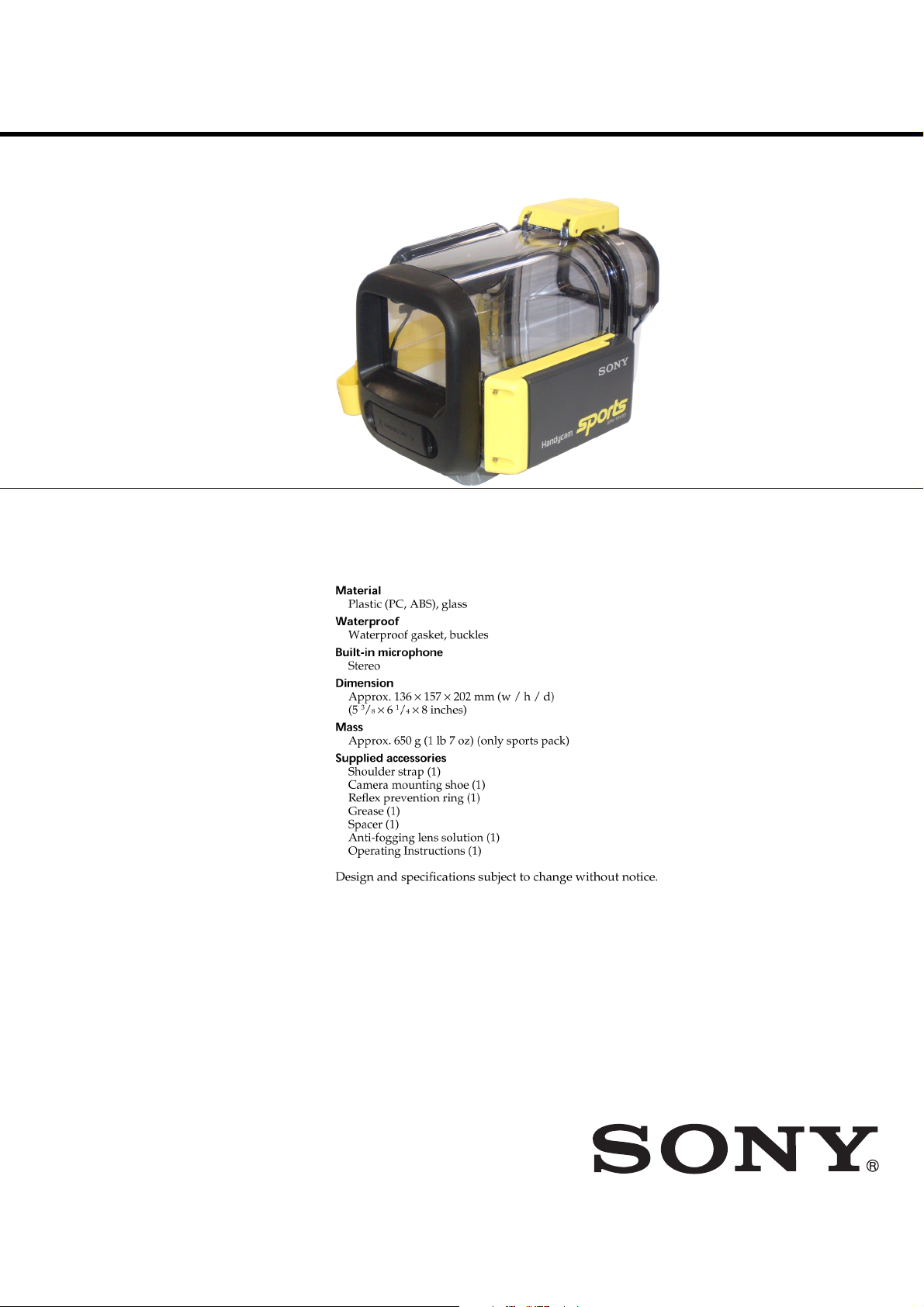
SPECIFICATIONS
AEP Model
SPORTS PACK
Page 2

SPK-TRV33
TABLE OF CONTENTS
1. GENERAL
Precautions ··················································································· 3
Maintenance and Precautions ······················································· 3
Troubleshooting············································································ 3
Preparing ······················································································ 3
Using the Sports Pack ··································································· 3
Recording ····················································································· 3
When Shooting with the LCD Screen ·········································· 3
Zooming ······················································································· 3
Recording a Still Picture ······························································· 3
Recording moving pictures on
the”Memory Stick” ······································································· 3
Playing Back with the Remote Commander ································ 3
Removing the Video Camera Recorder ········································ 3
2. REPAIR PARTS LIST
2.1 EXPLODED VIEWS ························································· 5
2-1-1.REAR CABINET SECTION ············································· 5
2-1-2.FRONT CABINET SECTION··········································· 6
ACCESSORIES LIST ·································································· 7
SAFETY-RELATED COMPONENT WARNING!!
COMPONENTS IDENTIFIED BY MARK 0 OR DOTTED LINE WITH
MARK 0 ON THE SCHEMATIC DIAGRAMS AND IN THE PARTS
LIST ARE CRITICAL TO SAFE OPERATION. REPLACE THESE
COMPONENTS WITH SONY PARTS WHOSE PART NUMBERS
APPEAR AS SHOWN IN THIS MANUAL OR IN SUPPLEMENTS
PUBLISHED BY SONY .
SAFETY CHECK-OUT
After correcting the original service problem, perform the following
safety checks before releasing the set to the customer.
1. Check the area of your repair for unsoldered or poorly-soldered
connections. Check the entire board surface for solder splashes
and bridges.
2. Check the interboard wiring to ensure that no wires are
"pinched" or contact high-wattage resistors.
3. Look for unauthorized replacement parts, particularly
transistors, that were installed during a previous repair. Point
them out to the customer and recommend their replacement.
ATTENTION AU COMPOSANT AYANT RAPPORT
À LA SÉCURITÉ!
LES COMPOSANTS IDENTIFÉS P AR UNE MARQUE 0 SUR LES
DIAGRAMMES SCHÉMA TIQUES ET LA LISTE DES PIÈCES SONT
CRITIQUES POUR LA SÉCURITÉ DE FONCTIONNEMENT. NE
REMPLACER CES COMPOSANTS QUE PAR DES PIÈSES SONY
DONT LES NUMÉROS SONT DONNÉS DANS CE MANUEL OU
DANS LES SUPPÉMENTS PUBLIÉS PAR SONY.
4. Look for parts which, through functioning, show obvious signs
of deterioration. Point them out to the customer and
recommend their replacement.
5. Check the B+ voltage to see it is at the values specified.
6. Flexible Circuit Board Repairing
• Keep the temperature of the soldering iron around 270˚C
during repairing.
• Do not touch the soldering iron on the same conductor of the
circuit board (within 3 times).
• Be careful not to apply force on the conductor when soldering
or unsoldering.
— 2 —
Page 3

SECTION 1
GENERAL
SPK-TRV33
— 3 —
Page 4

SPK-TRV33
9-876-209-11
Sony EMCS Co.
— 8 —
2004D1600-1
©2004.4
Published by DI Technical Support Section
Page 5

2.1 EXPLODED VIEWS
NOTE:
• -XX, -X mean standardized parts, so they may
have some differences from the original one.
• Items marked “*” are not stocked since they
are seldom required for routine service. Some
delay should be anticipated when ordering these
items.
2-1-1. REAR CABINET SECTION
8
7
SECTION 2
REPAIR PARTS LIST
• The mechanical parts with no reference number
in the exploded views are not supplied.
9
11
SPK-TRV33
The components identified by mark 0or
dotted line with mark 0 are critical for safety.
Replace only with part number specified.
Les composants identifiés par une marque
0 sont critiques pour la sécurité.
Ne les remplacer que par une pièce portant
le numéro spécifié.
17
12
11
10
11
6
5
4
3
(Note 1)
13
14
16
15
11
1
Ref. No. Part No. Description Ref. No. Part No. Description
1 3-081-528-01 EYE CUP
2 3-081-527-01 CASE, REAR
3 3-976-834-01 PLATE (UPPER), BUCKLE LOCK
4 3-951-813-11 SCREW (2X6) (TYPE 2), +K
0 5 3-081-530-01 PACKING, CABINET (Note1)
6 3-076-865-01 MIRROR
7 3-076-860-11 COVER, MIRROR
8 3-076-864-01 PIN, MIRROR HINGE
9 3-076-862-01 SLIDER, MIRROR
10 3-076-863-01 HOOD, MIRROR
2
17
11 3-076-866-01 BIND (2X6), TAPPING SCREW
12 3-081-529-01 BASE, MIRROR
13 3-960-764-21 BELT, GRIP
14 3-960-765-21 RING, GRIP BELT
15 3-052-424-01 SHAFT, GRIP
16 3-979-464-01 BRACKET (B), SHOULDER BELT
17 3-078-032-01 SHAFT, HINGE
18 3-078-155-01 RETAINER, GRIP
(Note1) When putting grease the cabinet packing (Ref. No. 5), al-
ways use the grease of the blue tube of the accessory.
When using the grease of the yellow tube and the grease
of the other Inc., it hurts a cabinet packing and it causes
the water leakage.
— 5 —
18
Page 6

SPK-TRV33
2-1-2. FRONT CABINET SECTION
ns : not supplied
Ver 1.1 2004. 05
56
61
68
53
52
51
75
55
54
67
(Note 2)
LS-065
58
61
ns
57
59
61
55
64
60
62
63
69
71
73
74
61
70
65
72
66
Ref. No. Part No. Description Ref. No. Part No. Description
51 3-076-877-01 BIND (2X5), TAPPING SCREW
52 3-076-873-01 PLATE, BUCKLE RETAINER
53 3-076-875-01 SPRING, BUCKLE
54 3-076-876-01 SLIDER, BUCKLE
0 55 3-076-871-01 SHAFT, BUCKLE
56 3-076-872-01 BUCKLE
0 57 3-073-881-01 CAP (RED), AIR PUNCHING
58 3-076-874-01 CAM, BUCKLE
59 3-081-534-01 COVER, FRONT
60 3-081-533-01 RETAINER, LENS WINDOW
61 3-076-866-01 BIND (2X6), TAPPING SCREW
62 3-081-532-01 WINDOW, LENS
0 63 3-081-535-01 PACKING, LENS WINDOW
64 X-3953-252-1 CASE ASSY, FRONT
65 3-083-164-01 HOLDER (A), CORD
66 3-951-813-11 SCREW (2X6) (TYPE 2), +K
67 A-7078-608-A LS-065 BOARD, COMPLETE (Note2)
68 3-081-531-01 COVER, CONTROL
69 1-542-543-11 UNIT (MIC)
* 70 3-959-469-01 PLATE, TRIPOD SCREW
0 71 3-959-461-01 PACKING, MICROPHONE
0 72 3-959-422-01 RING (P10), O
73 1-827-241-11 CORD, CONNECTION
74 A-7095-489-A MICROPHONE BLOCK ASSY
75 3-083-165-01 HOLDER (B), CORD
M
C
-143
ns
ns
ns
ns
(MC-143 board)
(Note2) In this model, parts are exchange in order to repair only
the mounted board.
The marked “0” are parts in relation to waterproof.
Replace these components with Sony parts.
Be sure to check up waterproof after repair.
— 6 —
Page 7

Ref. No. Part No. Description
ACCESSORIES
************
3-081-549-01 BASE (A)
* 3-970-217-01 SCREW, CAMERA FITTING
2-391-512-00 RING (5), RETAINING, E TYPE
3-941-465-01 BELT, STRAP
3-953-086-01 BRACKET
3-055-231-01 RING (30), PREVENTION
0 3-071-370-01 GREASE (BLUE)
3-943-913-01 STOPPER KIT
3-081-548-11 OPERATING INSTRUCTIONS
(ENGLISH , FRENCH, GERMAN, SPANISH)
3-081-548-21 OPERATING INSTRUCTIONS
(PORTUGUESE, SWEDISH, ITALIAN, DUTCH)
3-081-548-31 OPERATING INSTRUCTIONS
(RUSSIAN, ARABIC, CHINESE, KOREAN)
The marked “0” are parts in relation to waterproof.
Replace these components with Sony parts.
Be sure to check up waterproof after repair.
SPK-TRV33
— 7 —
Page 8

SPK-TRV33
9-876-209-11
Sony EMCS Co.
— 8 —
2004E1600-1
©2004.5
Published by DI Technical Support Section
Page 9

Reverse
987620912.pdf
Revision History
Ver.
1.0
1.1
Date
2003.01
2004.05
History
Official Release
Correction-1
Contents
—
Correction of the repair parts list.
S.M. correction: Page 6
S.M. Rev.
issued
—
Ye s
 Loading...