

1257-2928 Rev 4
Sony Mobile Communications AB – Company Internal
Working Instructions
- mechanical -
Xperia S
LT26i, SO-02D

1257-2928 Rev 4
Sony Mobile Communications AB – Company Internal
2(90)
Working Instructions (mech)
CONTENTS
1 Exterior Views ................................................................................. 4
1.1 LT26i ..................................................................................................... 4
2 Tools ................................................................................................ 5
3 Disassembly.................................................................................... 6
3.1 Cover Rear Assy .................................................................................. 6
3.2 Cover Bottom ....................................................................................... 6
3.3 Battery ................................................................................................... 7
3.4 Rear Frame Assy .................................................................................. 8
3.5 Main Camera ......................................................................................... 9
3.6 Main PBA .............................................................................................. 9
3.7 Cover Transparent Assy & Cover Front Assy .................................. 11
4 Replacement ................................................................................. 13
4.1 Cover Rear Assy ................................................................................ 13
4.2 Cover Bottom ..................................................................................... 13
4.3 Battery ................................................................................................. 13
4.4 Rear Frame Assy ................................................................................ 13
4.5 Main Camera ....................................................................................... 14
4.6 Cover Front Assy ............................................................................... 14
4.7 Cover Transparent Assy .................................................................... 14
4.8 Ant GPS .............................................................................................. 15
4.9 Audio Jack .......................................................................................... 17
4.10 Cap HDMI ............................................................................................ 19
4.11 Cap RF ................................................................................................ 20
4.12 Cap USB .............................................................................................. 21
4.13 Carrier Holder Bottom ........................................................................ 23
4.14 Carrier Holder Proximity Sensor ....................................................... 24
4.15 Carrier Vibrator ................................................................................... 25
4.16 Core Unit Label ................................................................................... 26
4.17 Cushion Camera 1 .............................................................................. 28
4.18 Cushion Receiver ............................................................................... 29
4.19 Cushion Speaker ................................................................................ 31
4.20 Cushion Sub PBA .............................................................................. 33
4.21 Cushion Vib ........................................................................................ 35
4.22 Ear Speaker ........................................................................................ 36
4.23 Foil Adhesive Audio Jack .................................................................. 38
4.24 Foil Adhesive GPS Ant ...................................................................... 40
4.25 Foil Adhesive NFC PBA ..................................................................... 42
4.26 Foil Adhesive Speaker ....................................................................... 44
4.27 Foil Adhesive Transparent Front ...................................................... 46

1257-2928 Rev 4
Sony Mobile Communications AB – Company Internal
3(90)
Working Instructions (mech)
4.28 FPC Jack Assy ................................................................................... 48
4.29 FPC Main Assy ................................................................................... 50
4.30 Key Camera ........................................................................................ 54
4.31 Key On/Off .......................................................................................... 55
4.32 Key Volume ........................................................................................ 56
4.33 Loudspeaker ....................................................................................... 57
4.34 Main Antenna ...................................................................................... 59
4.35 NFC Antenna ...................................................................................... 61
4.36 PBA Bottom ........................................................................................ 62
4.37 PBA NFC ............................................................................................. 63
4.38 RF Cable ............................................................................................. 65
4.39 Sheet GPS Ant .................................................................................... 66
4.40 Sheet LCD FPC ................................................................................... 67
4.41 Sheet NFC FPC ................................................................................... 69
4.42 Sheet NFC Shield ............................................................................... 70
4.43 Sheet Protection LCD ........................................................................ 72
4.44 Shield Can BB A ................................................................................. 73
4.45 Shield Can BB B ................................................................................. 74
4.46 Shield Can Lid Non Cell ..................................................................... 75
4.47 Shield Can RF ..................................................................................... 76
4.48 Water Indicator ................................................................................... 77
4.49 Water Indicator L ................................................................................ 78
4.50 Board Swap - Replacement ............................................................... 79
4.51 Board Swap – Change Label ............................................................. 79
5 Reassembly................................................................................... 80
5.1 Cover Front Assy & Cover Transparent Assy .................................. 80
5.2 Main PBA ............................................................................................ 83
5.3 Main Camera ....................................................................................... 84
5.4 Rear Frame Assy ................................................................................ 85
5.5 Battery ................................................................................................. 85
5.6 Cover Bottom ..................................................................................... 87
5.7 Cover Rear Assy ................................................................................ 88
6 Country of Origin Barcodes for Brazil/VIVO Labels .................. 89
7 Revision History ........................................................................... 90
For general information about mechanical repair related issues, refer to
1220-1333: Generic Repair Manual - mechanical
1257-2928 Rev 4
Sony Mobile Communications AB – Company Internal
4(90)
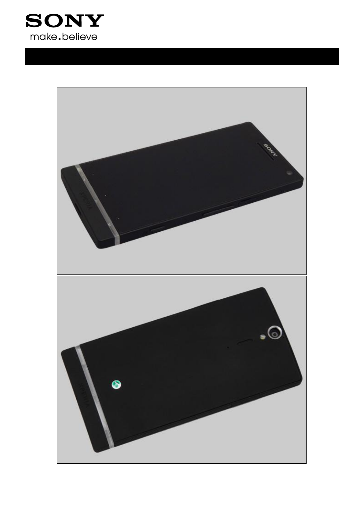
1 Exterior Views
1.1 LT26i
Working Instructions (mech)
1257-2928 Rev 4
Sony Mobile Communications AB – Company Internal
5(90)
2 Tools
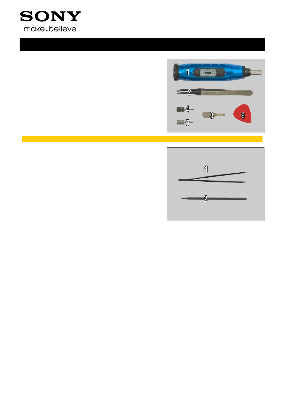
SPECIAL TOOLS
1. Torque Screwdriver
2. Flex Film Assembly Tool
3. Front Opening Tool
4. Bits(T5)
5. Bits(JCIS No 0)
6. Guitar Pick
For part no’s on the tools above, refer to the ‘Tools Catalogue/Matrix’!
STANDARD TOOLS
1. Tweezers
2. Nylon Pointer
Working Instructions (mech)
1257-2928 Rev 4
Sony Mobile Communications AB – Company Internal
6(90)
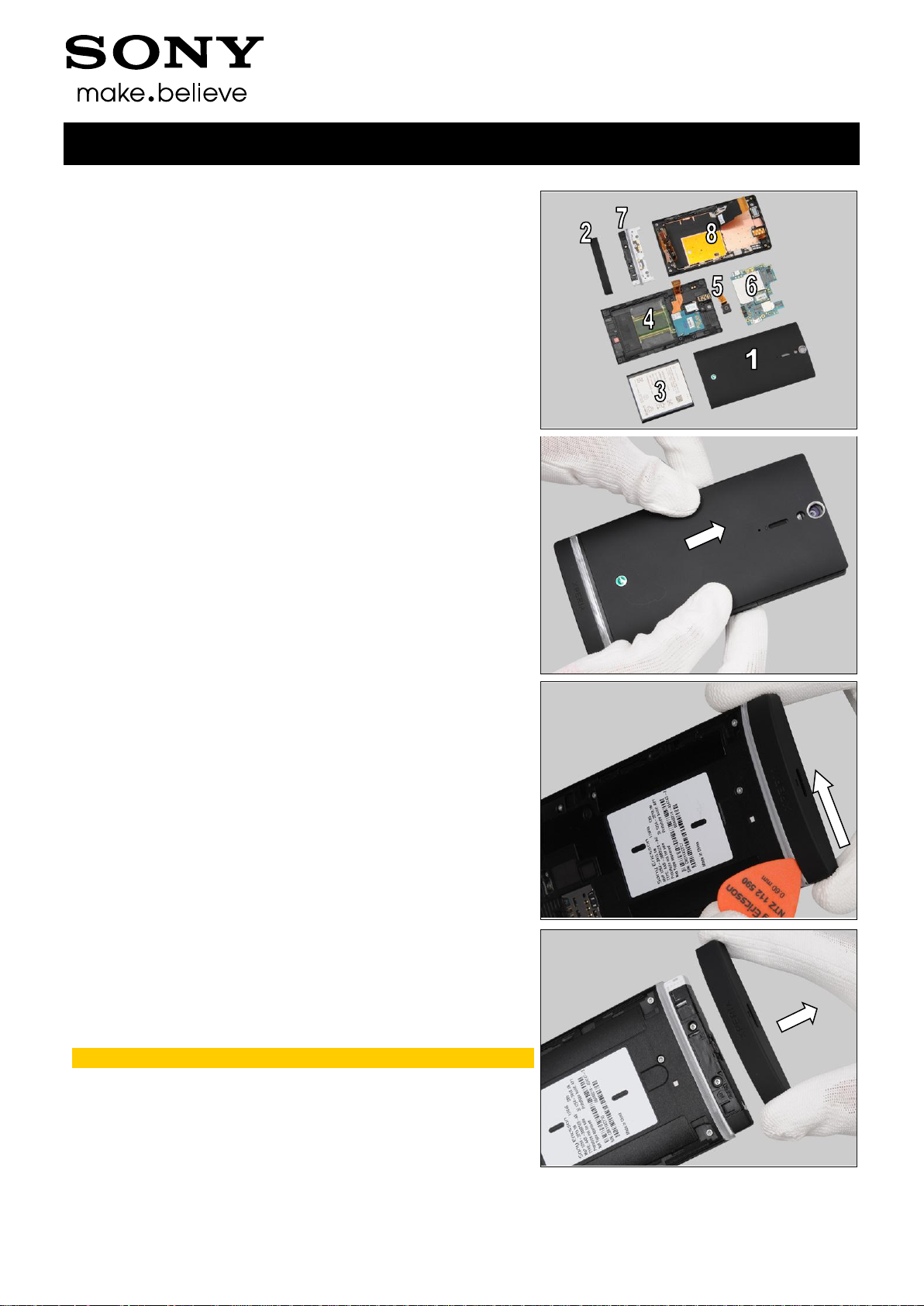
The disassembly is done in the following order:
1. Cover Rear Assy
2. Cover Bottom
3. Battery
4. Rear Frame Assy
5. Main Camera
6. Main PBA
7. Cover Transparent Assy
8. Cover Front Assy
3.1 Cover Rear Assy
Push upwards to unsnap the hooks of the Cover Rear Assy
from the bottom gently and remove it.
3.2 Cover Bottom
Push the Cover Bottom to show the gap between the Cover
Bottom and the Cover Transparent Assy with your fingers
and insert Guitar Pick to release the hooks of the Cover
Bottom.
Remove the Cover Bottom with your fingers.
Scrap! Not to be reused!
3 Disassembly
Working Instructions (mech)
1257-2928 Rev 4
Sony Mobile Communications AB – Company Internal
7(90)
Disassembly
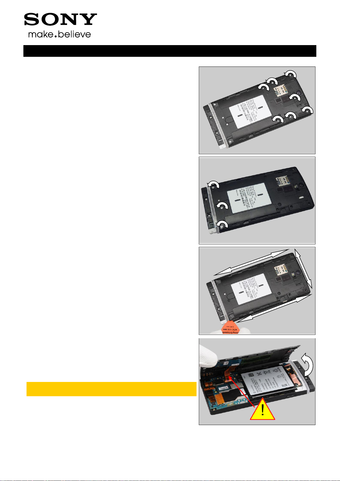
3.3 Battery
Remove the seven screws Len:3.5 Diam:1.4 by T5.
Remove the three screws Len:3.5 Diam:1.4M by Bits(JCIS
No 0).
Insert the Guitar Pick from the right bottom as shown in the
picture and gently slide back and forth to release the hooks
of the Rear Frame.
Raise the left side of the Rear Frame approximately 60°
from the right side.
Do not open the cover more than 60° and do not stretch
the NFC PFC!
Working Instructions (mech)
1257-2928 Rev 4
Sony Mobile Communications AB – Company Internal
8(90)
Disassembly
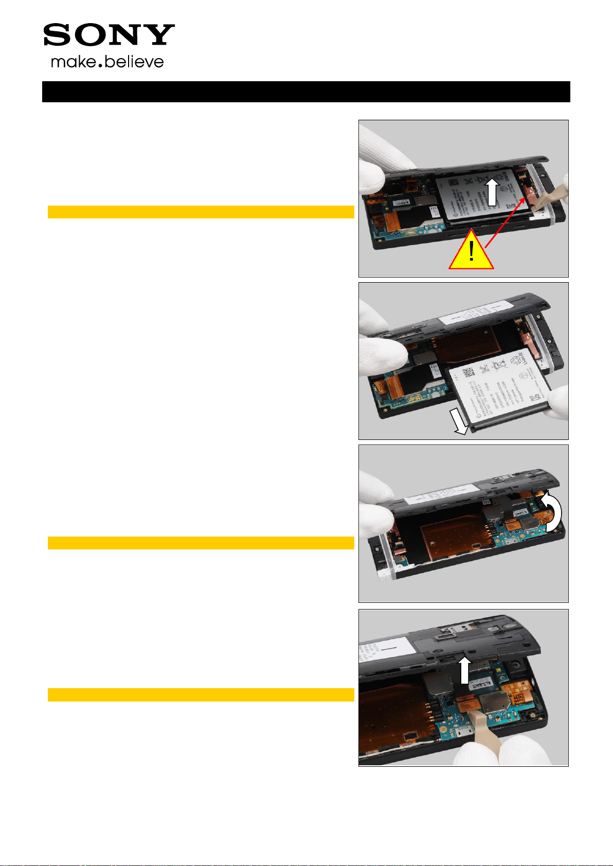
Insert the Front Opening Tool and raise the bottom of the
Battery to release it.
Do not touch the FPC area beside the Battery!
Remove the Battery.
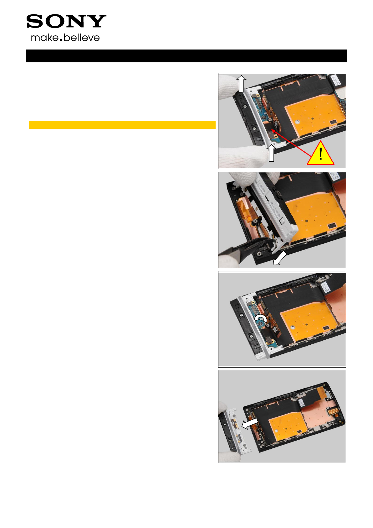
3.4 Rear Frame Assy
Change to raise another side of the Rear Frame.
Do not open the Rear Frame Assy more than 60°!
Unsnap the BtB connector by using the Front Opening Tool.
No conductive tools should be used!
Working Instructions (mech)
1257-2928 Rev 4
Sony Mobile Communications AB – Company Internal
9(90)
Disassembly
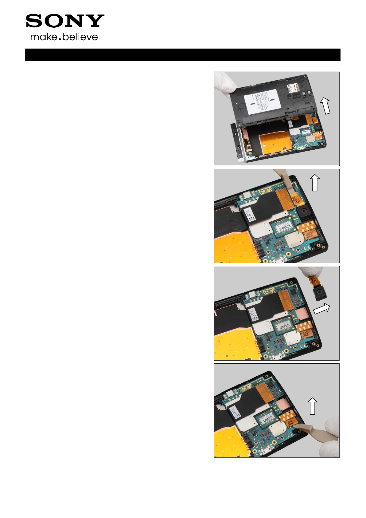
Remove the Rear Frame Assy with your fingers.
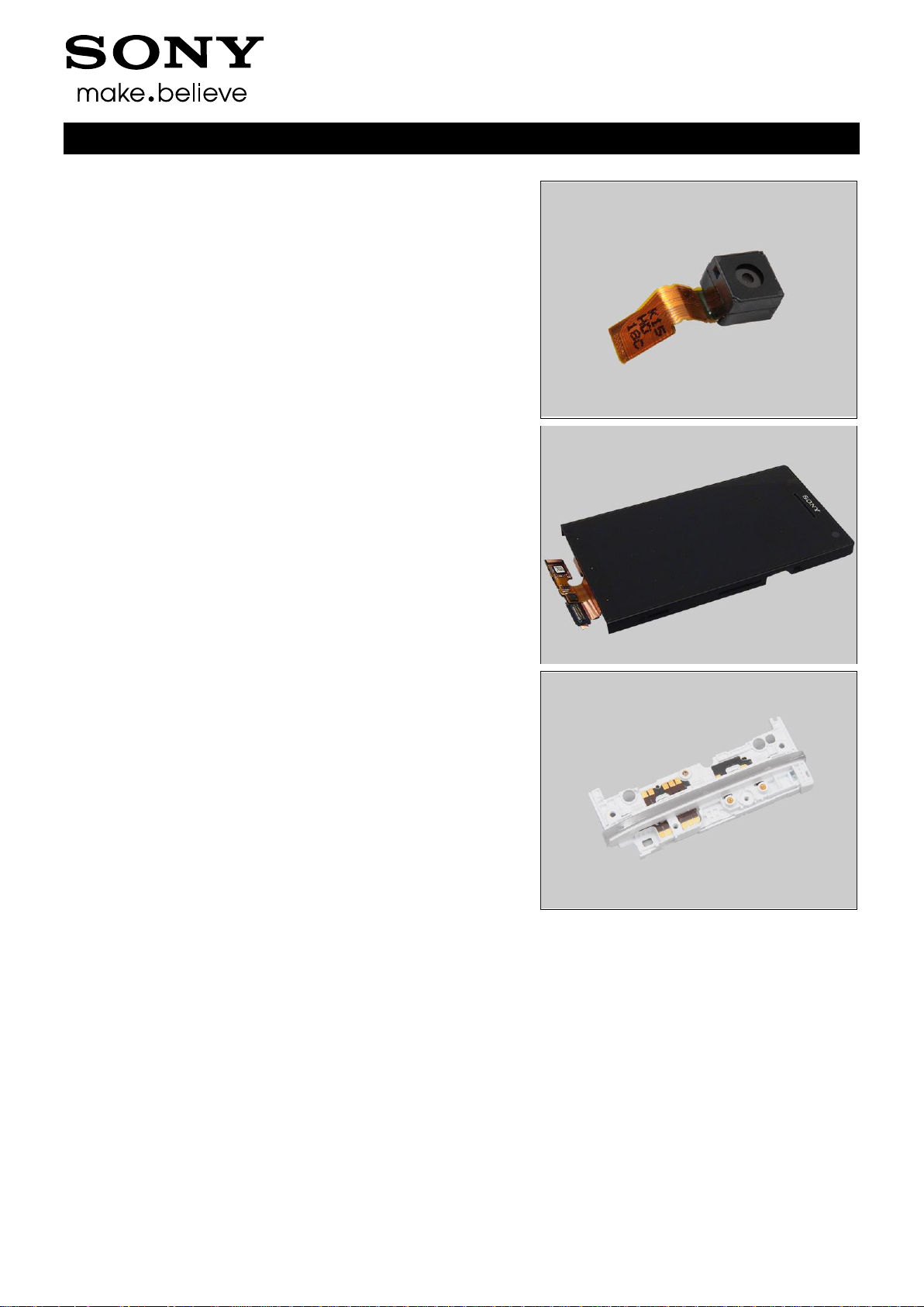
3.5 Main Camera
Unsnap the BtB connector by using the Front Opening Tool.
Remove the Main Camera with your fingers.
3.6 Main PBA
Unsnap the FPC Jack BtB connector by using the Front
Opening Tool.
Working Instructions (mech)

1257-2928 Rev 4
Sony Mobile Communications AB – Company Internal
10(90)
Disassembly
Unsnap the Main FPC BtB connector by using the Front
Opening Tool.
Insert the Front Opening Tool to release the Main PBA.
Turn the main PBA over gently.
Do not stretch the RF Cable!
Unsnap one side of the RF Cable by using the Front
Opening Tool.
Working Instructions (mech)
1257-2928 Rev 4
Sony Mobile Communications AB – Company Internal
11(90)
Disassembly
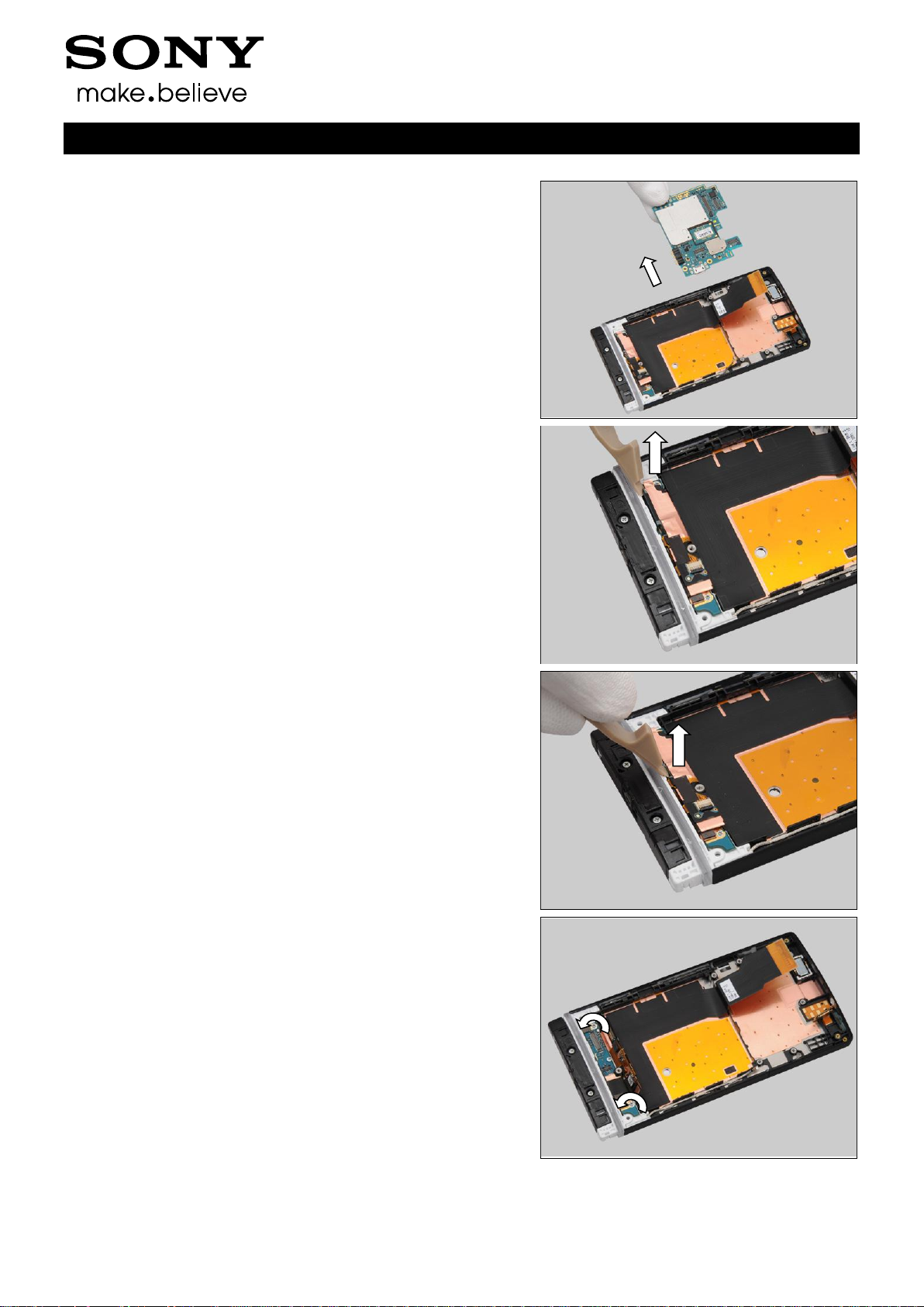
Remove the Main PBA with your fingers.
3.7 Cover Transparent Assy
& Cover Front Assy
Unsnap the LCD BtB connector by using the Front Opening
Tool.
Unsnap the touch panel BtB connector by using the Front
Opening Tool.
Remove the two screws Len:3.5 Diam:1.4M by Bits(JCIS No
0).
Working Instructions (mech)
1257-2928 Rev 4
Sony Mobile Communications AB – Company Internal
12(90)
Disassembly
Lift up the Cover Transparent and Turn it over gently.
Do not open the Sheet ACF Relay from the PBA!
Unsnap one side of the RF Cable by using the Flex Film
Assembly Tool.
Remove the one screw Len:2.0 Diam:1.4 by Bits(JCIS No
0).
Remove the Cover Transparent Assy.
Working Instructions (mech)

1257-2928 Rev 4
Sony Mobile Communications AB – Company Internal
13(90)
4.1 Cover Rear Assy
Follow the 3.1 Disassembly instructions!
Prepare the new Cover Rear Assy.
Follow the 5.7 Reassembly instructions!
4.2 Cover Bottom
Follow the 3.2 Disassembly instructions!
Prepare the new Cover Bottom.
Follow the 5.6 Reassembly instructions!
4.3 Battery
Follow the 3.1 – 3.3 Disassembly instructions!
Prepare the new Battery.
Follow the 5.5 – 5.7 Reassembly instructions!
4.4 Rear Frame Assy
Follow the 3.1 – 3.4 Disassembly instructions!
Follow the 4.8, 4.9, 4.11, 4.36, Removal instructions!
Prepare the new Rear Frame Assy.
Follow the 4.8, 4.9, 4.11, 4.16, 4.23, 4.24, 4.25, 4.26, 4.33,
4.35, 4.37, 4.48, 4.49 Installation instructions!
Follow the 5.4 – 5.7 Reassembly instructions!
4 Replacement
Working Instructions (mech)
1257-2928 Rev 4
Sony Mobile Communications AB – Company Internal
14(90)
Replacement
4.5 Main Camera
Follow the 3.1 – 3.5 Disassembly instructions!
Prepare a new Main Camera.
Follow the 4.17 Installation instructions!
Follow the 5.3 – 5.7 Reassembly instructions!
4.6 Cover Front Assy
Follow the 3.1 – 3.7 Disassembly instructions!
Follow the 4.10, 4.12, 4.14, 4.22, 4.28, 4.30, 4.31, 4.32, 4.38
Removal instructions!
Prepare a new Cover Front Assy.
Follow the 4.10, 4.12, 4.14, 4.18, 4.20, 4.22, 4.28, 4.29,
4.30, 4.31, 4.32, 4.38 Installation instructions!
Follow the 5.1 – 5.7 Reassembly instructions!
4.7 Cover Transparent Assy
Follow the 3.1 – 3.4, 3.7 Disassembly instructions!
Follow the 4.13, 4.34, 4.36 Removal instructions!
Prepare the new Cover Transparent Assy.
Follow the 4.13, 4.27, 4.34, 4.36 Installation instructions!
Follow the 5.1, 5.4 – 5.7 Reassembly instructions!
Working Instructions (mech)
1257-2928 Rev 4
Sony Mobile Communications AB – Company Internal
15(90)
Follow the 3.1 – 3.4 Disassembly instructions!
Follow the 4.24 Removal instructions!
Carry out the Removal as described below.
Prepare the new Ant GPS.
Carry out the Installation as described below.
Follow the 4.39 Installation instructions!
Follow the 4.24 Installation instructions!
Follow the 5.4 – 5.7 Reassembly instructions!
REMOVAL
Detach the Ant GPS by using the Front Opening Tool.
Remove it with your fingers.
INSTALLATION
Place the new Ant GPS in the correct position.
Replacement
4.8 Ant GPS
Working Instructions (mech)
1257-2928 Rev 4
Sony Mobile Communications AB – Company Internal
16(90)
Press to secure its attachment.
Replacement: Ant GPS
Working Instructions (mech)
1257-2928 Rev 4
Sony Mobile Communications AB – Company Internal
17(90)
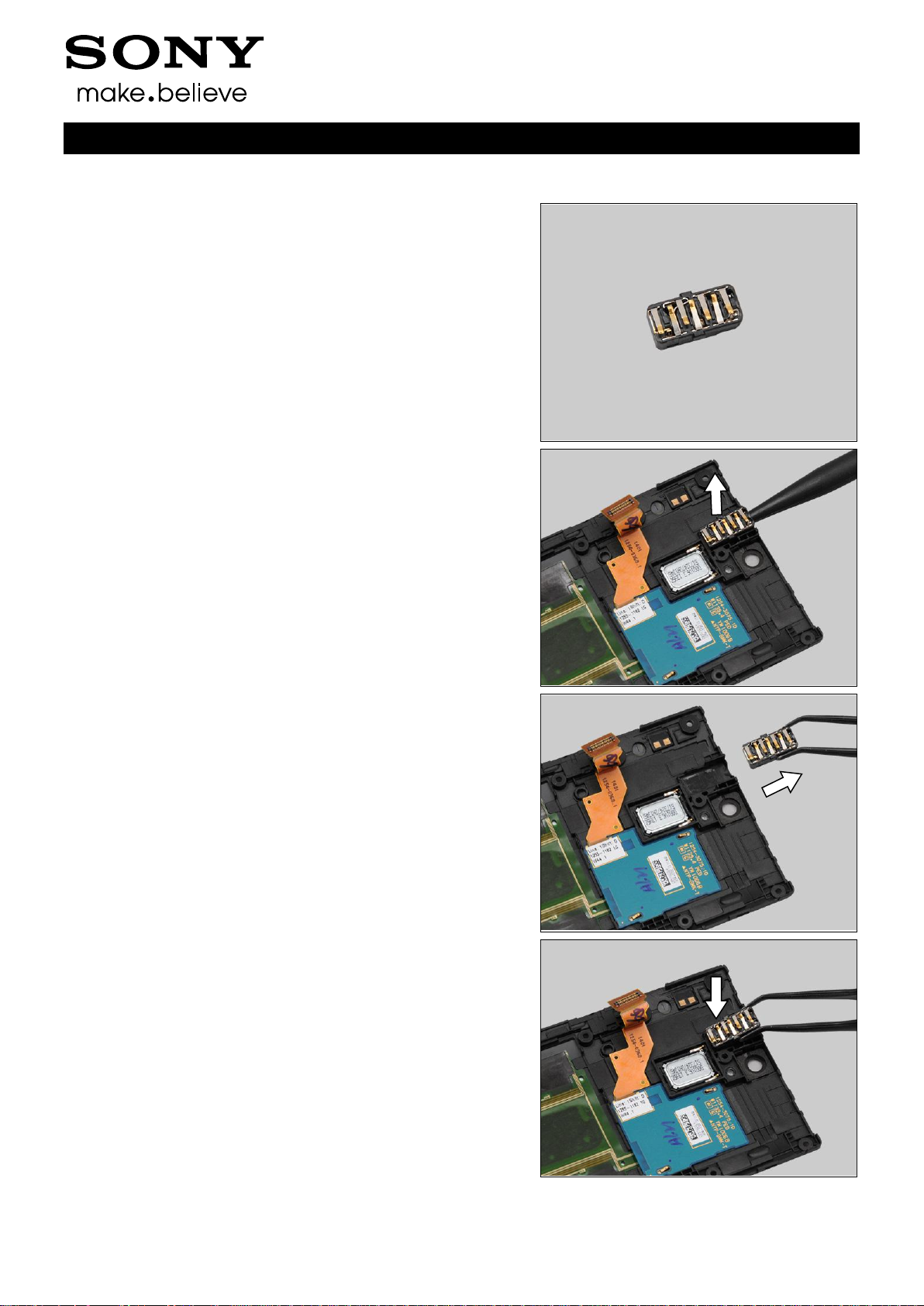
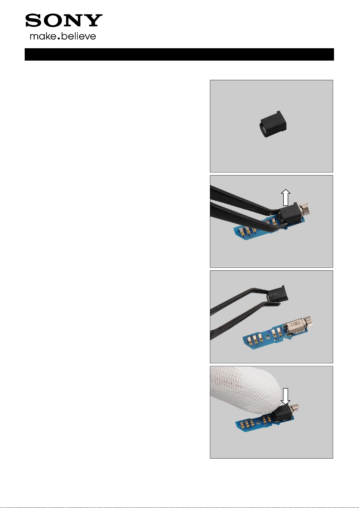
Follow the 3.1 – 3.4 Disassembly instructions!
Follow the 4.23 Removal instructions!
Carry out the Removal as described below.
Prepare the new Audio Jack
Follow the 4.23 Installation instructions!
Carry out the Installation as described below.
Follow the 5.4 – 5.7 Reassembly instructions!
REMOVAL
Insert the Nylon Pointer into the hole of the Audio Jack
connector to release it.
Remove the Audio Jack by using the Flex Film Assembly
Tool.
INSTALLATION
Place the new Audio Jack into its socket.
Replacement
4.9 Audio Jack
Working Instructions (mech)
1257-2928 Rev 4
Sony Mobile Communications AB – Company Internal
18(90)
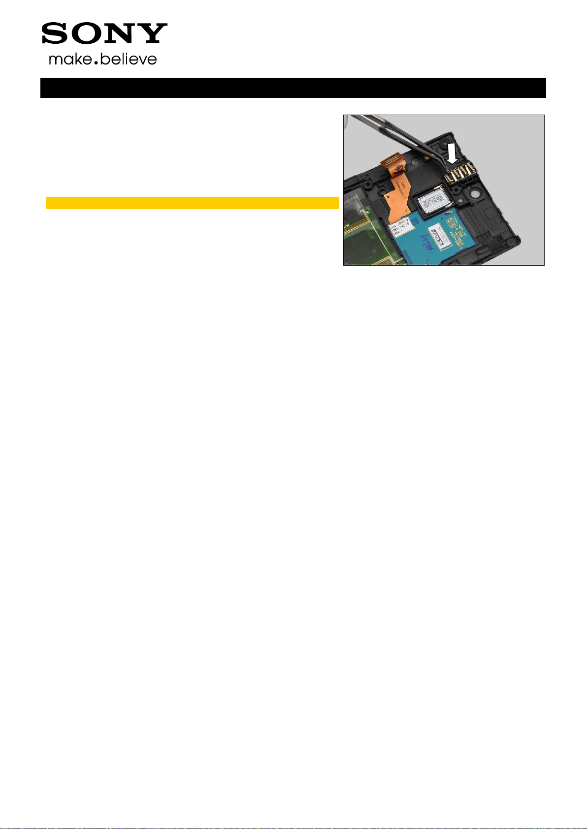
Press to secure its position by using the Flex Film Assembly
Tool.
Do not touch the contact pins on the Audio Jack!
Replacement: Audio Jack
Working Instructions (mech)
1257-2928 Rev 4
Sony Mobile Communications AB – Company Internal
19(90)
Follow the 3.1 – 3.6 Disassembly instructions!
Carry out the Removal as described below.
Prepare the new Cap HDMI.
Carry out the Installation as described below.
Follow the 5.2 – 5.7 Reassembly instructions!
REMOVAL
Lift up the Cap HDMI to remove it with your fingers.
INSTALLATION
Place the Cap HDMI in the correct position as shown in the
picture.
Press to secure its position.
Replacement
4.10 Cap HDMI
Working Instructions (mech)
1257-2928 Rev 4
Sony Mobile Communications AB – Company Internal
20(90)
Replacement
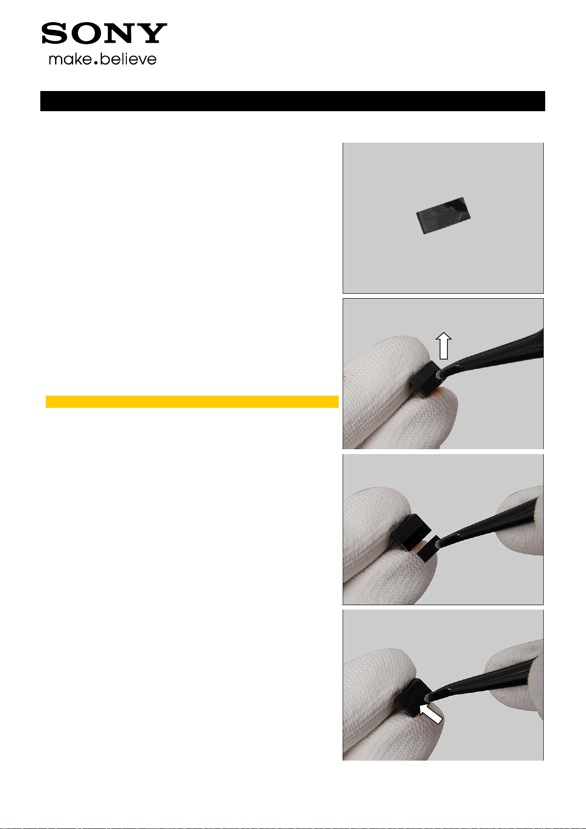
Follow the 3.1 Disassembly instructions!
Carry out the Removal as described below.
Prepare the new Cap RF.
Carry out the Installation as described below.
Follow the 5.7 Reassembly instructions!
REMOVAL
Lift up the Cap RF by using the Tweezers and remove it.
INSTALLATION
Place the new Cap RF in the correct position.
Press the Cap RF into its proper position.
4.11 Cap RF
Working Instructions (mech)
1257-2928 Rev 4
Sony Mobile Communications AB – Company Internal
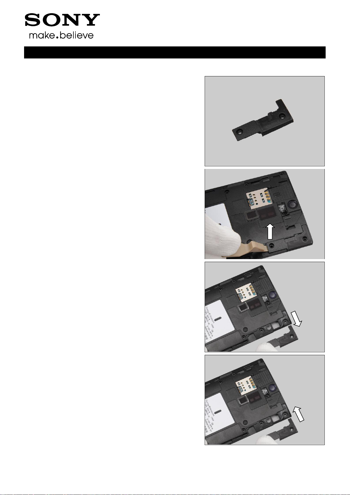
21(90)
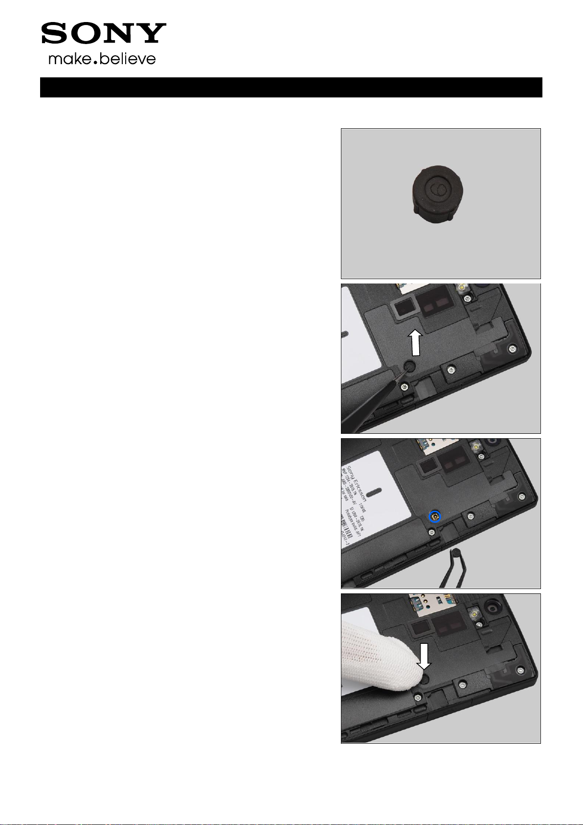
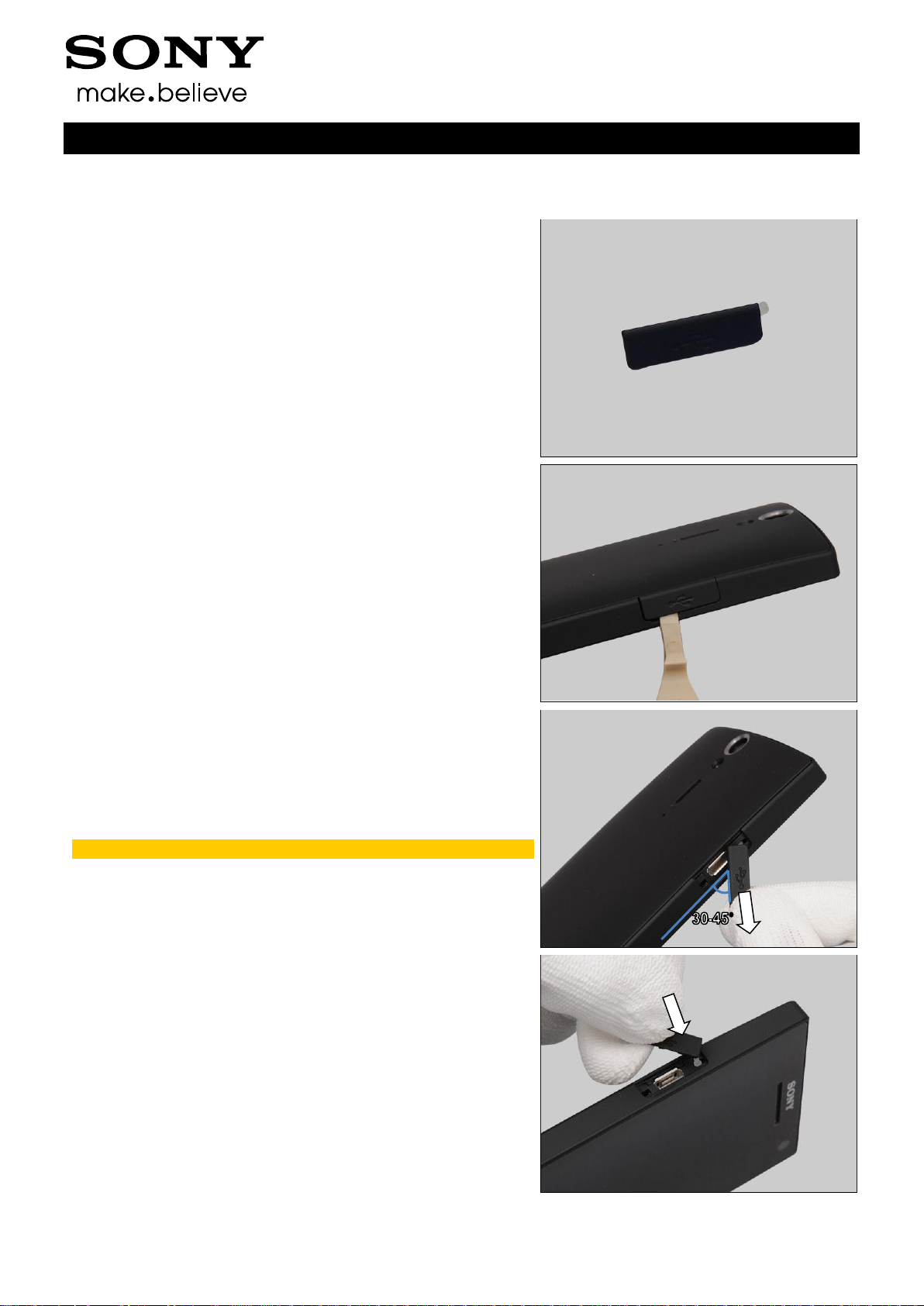
Carry out the Removal as described below
Prepare the new Cap USB.
Carry out the Installation as described below.
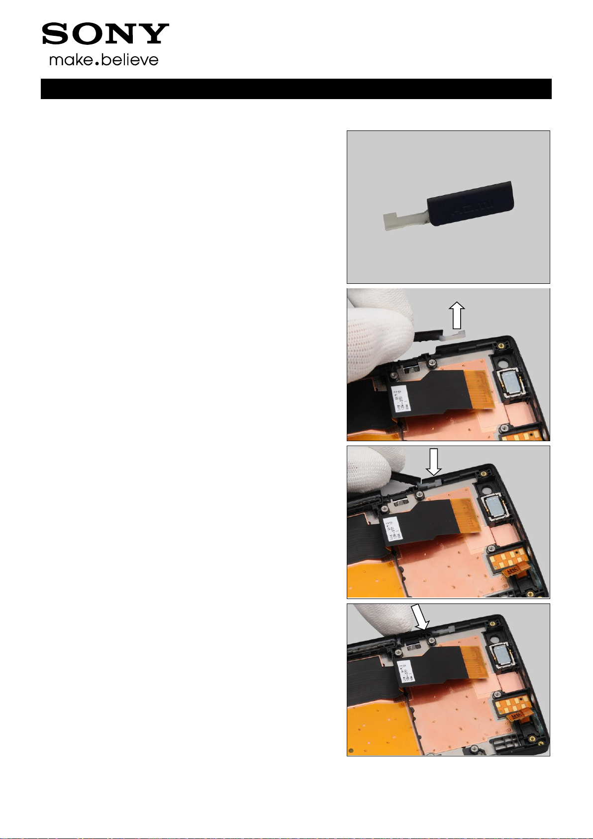
REMOVAL
Insert the Front Opening Tool to release the Cap USB.
Gently lift up the Cap USB at 30-45 degree as shown in
picture and pull to release it from its hole with fingers.
Scrap! Not to be reused!
INSTALLATION
Insert the Cap USB into its hole with fingers.
Replacement
4.12 Cap USB
Working Instructions (mech)
1257-2928 Rev 4
Sony Mobile Communications AB – Company Internal
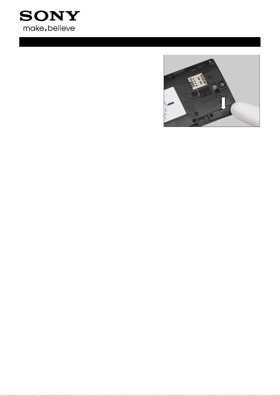
22(90)
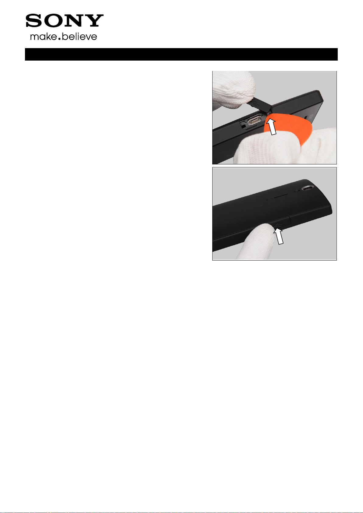
Push the pump of the Cap USB into the hole by using a
Guitar Pick.
Press to secure its position.
Replacement: Cap USB
Working Instructions (mech)
1257-2928 Rev 4
Sony Mobile Communications AB – Company Internal
23(90)
Follow the 3.1 – 3.4 Disassembly instructions!
Follow the 4.34 Removal instruction!
Carry out the Removal as described below.
Prepare the new Carrier Holder Bottom.
Carry out the Installation as described below.
Follow the 4.34, 4.21 Installation instructions!
Follow the 5.4 – 5.7 Reassembly instructions!
REMOVAL
Remove the Carrier Holder Bottom with your fingers.
INSTALLATION
Place the Carrier Holder Bottom in the correct position.
Press to secure its position.
The guiding hole must be aligned accurately between
the Carrier Holder Bottom and the PBA Bottom!
Replacement
4.13 Carrier Holder Bottom
Working Instructions (mech)
1257-2928 Rev 4
Sony Mobile Communications AB – Company Internal
24(90)
Follow the 3.1 – 3.6 Disassembly instructions!
Follow the 4.28 Removal instructions!
Carry out the Removal as described below.
Prepare the new Carrier Holder Proximity Sensor.
Carry out the Installation as described below.
Follow the 4.28 Installation instructions!
Follow the 5.2 – 5.7 Reassembly instructions!
REMOVAL
Detach the Carrier Holder Proximity Sensor by using the
Tweezers and remove it.
INSTALLATION
Place the Carrier Holder Proximity Sensor in the correct
position.
Press to secure its position.
Replacement
4.14 Carrier Holder Proximity Sensor
Working Instructions (mech)
1257-2928 Rev 4
Sony Mobile Communications AB – Company Internal
25(90)
Follow the 3.1 – 3.4 Disassembly instructions!
Follow the 4.34, 4.13, 4.36 Removal instructions!
Carry out the Removal as described below.
Prepare the new Carrier Vibrator.
Carry out the Installation as described below.
Follow the 4.34, 4.13, 4.36 Installation instructions!
Follow the 5.4 – 5.7 Reassembly instructions!
REMOVAL
Detach the Carrier Vibrator by using the Flex Film Assembly
Tool and remove it.
INSTALLATION
Place the new Carrier Vibrator in the correct position.
Press to secure its position.
Replacement
4.15 Carrier Vibrator
Working Instructions (mech)
1257-2928 Rev 4
Sony Mobile Communications AB – Company Internal
26(90)
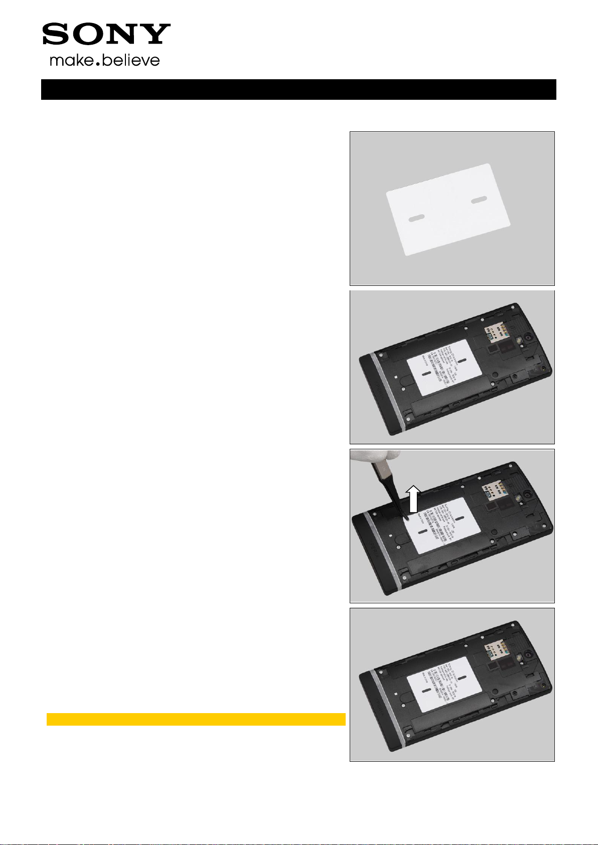
Follow the 3.1 Disassembly instructions!
Carry out the Removal as described below.
Prepare the new Core Unit Label.
Carry out the Installation as described below.
Follow the 5.7 Reassembly instructions!
REMOVAL
Read the old Label Core Unit and write the information into
the ‘LabelMake’ program.
Carefully remove the Label by using the Flex Film Assembly
Tool.
INSTALLATION
Check that the proper label format is loaded in the Zebra
printer and write a new Label by using the ‘Label Make’
software.
One label only is allowed!
Replacement
4.16 Core Unit Label
Working Instructions (mech)
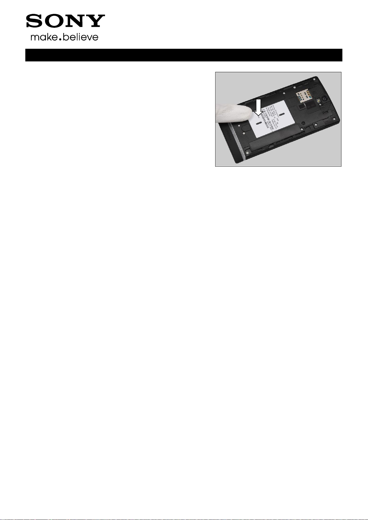
1257-2928 Rev 4
Sony Mobile Communications AB – Company Internal
27(90)
Press along the surface to make Label securely attached.
Replacement: Core Unit Lable
Working Instructions (mech)
1257-2928 Rev 4
Sony Mobile Communications AB – Company Internal
28(90)
Follow the 3.1 – 3.5 Disassembly instructions!
Carry out the Removal as described below.
Prepare the new Cushion Camera 1.
Carry out the Installation as described below.
Follow the 5.3 – 5.7 Reassembly instructions!
REMOVAL
Peel off the Cushion Camera 1 by using the Flex Film
Assembly Tool.
Scrap! Not to be reused!
INSTALLATION
Place the new Cushion Camera 1 in the correct position.
Press to secure its attachment.
Replacement
4.17 Cushion Camera 1
Working Instructions (mech)

1257-2928 Rev 4
Sony Mobile Communications AB – Company Internal
29(90)
Follow the 3.1 –3.6 Disassembly instructions!
Follow the 4.22 Removal instructions!
Carry out the Removal as described below.
Prepare the new Cushion Receiver.
Carry out the Installation as described below.
Follow the 4.22 Installation instructions!
Follow the 5.2 – 5.7 Reassembly instructions!
REMOVAL
Peel off the Cushion Receiver by using the Tweezers.
Scrap! Not to be reused!
INSTALLATION
Place the Cushion Receiver in the correct position.
Press to secure its attachment.
Replacement
4.18 Cushion Receiver
Working Instructions (mech)

1257-2928 Rev 4
Sony Mobile Communications AB – Company Internal
30(90)
Peel off the protective film.
Replacement: Cushion Receiver
Working Instructions (mech)

1257-2928 Rev 4
Sony Mobile Communications AB – Company Internal
31(90)
Follow the 3.1– 3.6 Disassembly instructions!
Carry out the Removal as described below.
Prepare the new Cushion Speaker.
Carry out the Installation as described below.
Follow the 5.2 – 5.7 Reassembly instructions!
REMOVAL
Peel off the Cushion Speaker by using the Tweezers.
Scrap! Not to be reused!
INSTALLATION
Place the Cushion Speaker aligning the Shield Can BB B
guide lines as shown in the picture.
Press to secure its attachment.
Replacement
4.19 Cushion Speaker
Working Instructions (mech)

1257-2928 Rev 4
Sony Mobile Communications AB – Company Internal
32(90)
Peel off the protective film.
Turn over the main PBA to make sure the Cushion Speaker
proper assembly.
Cushion Speaker should be within marked PBA guiding
area! PBA overhang is not allowed!
Replacement: Cushion Speaker
Working Instructions (mech)

1257-2928 Rev 4
Sony Mobile Communications AB – Company Internal
33(90)
Follow the 3.1 – 3.4 Disassembly instructions!
Carry out the Removal as described below.
Prepare the new Cushion Sub PBA.
Carry out the Installation as described below.
Follow the 5.4 – 5.7 Reassembly instructions!
REMOVAL
Unsnap the LCD BtB connectors by using the Front Opening
Tool.
Unsnap the touch panel BtB connectors by using the Front
Opening Tool.
Peel off the Cushion Sub PBA by using the Flex Film
Assembly Tool.
Scrap! Not to be reused!
Replacement
4.20 Cushion Sub PBA
Working Instructions (mech)

1257-2928 Rev 4
Sony Mobile Communications AB – Company Internal
34(90)
INSTALLATION
Place the new Cushion Sub PBA aligning the guiding line as
shown in the picture.
Press to secure its attachment.
Replacement: Cushion Sub PBA
Working Instructions (mech)

1257-2928 Rev 4
Sony Mobile Communications AB – Company Internal
35(90)
Follow the 3.1 –3.4 Disassembly instructions!
Follow the 4.34, 4.13 Removal instructions!
Carry out the Removal as described below.
Prepare the new Cushion Vib.
Carry out the Installation as described below.
Follow the 4.34, 4.13 Installation instructions!
Follow the 5.4 – 5.7 Reassembly instructions!
REMOVAL
Peel off the Cushion Vib by using the Flex Film Assembly
Tool.
Scrap! Not to be reused!
INSTALLATION
Place the Cushion Vib in the correct position.
Press to secure its attachment.
Replacement
4.21 Cushion Vib
Working Instructions (mech)

1257-2928 Rev 4
Sony Mobile Communications AB – Company Internal
36(90)
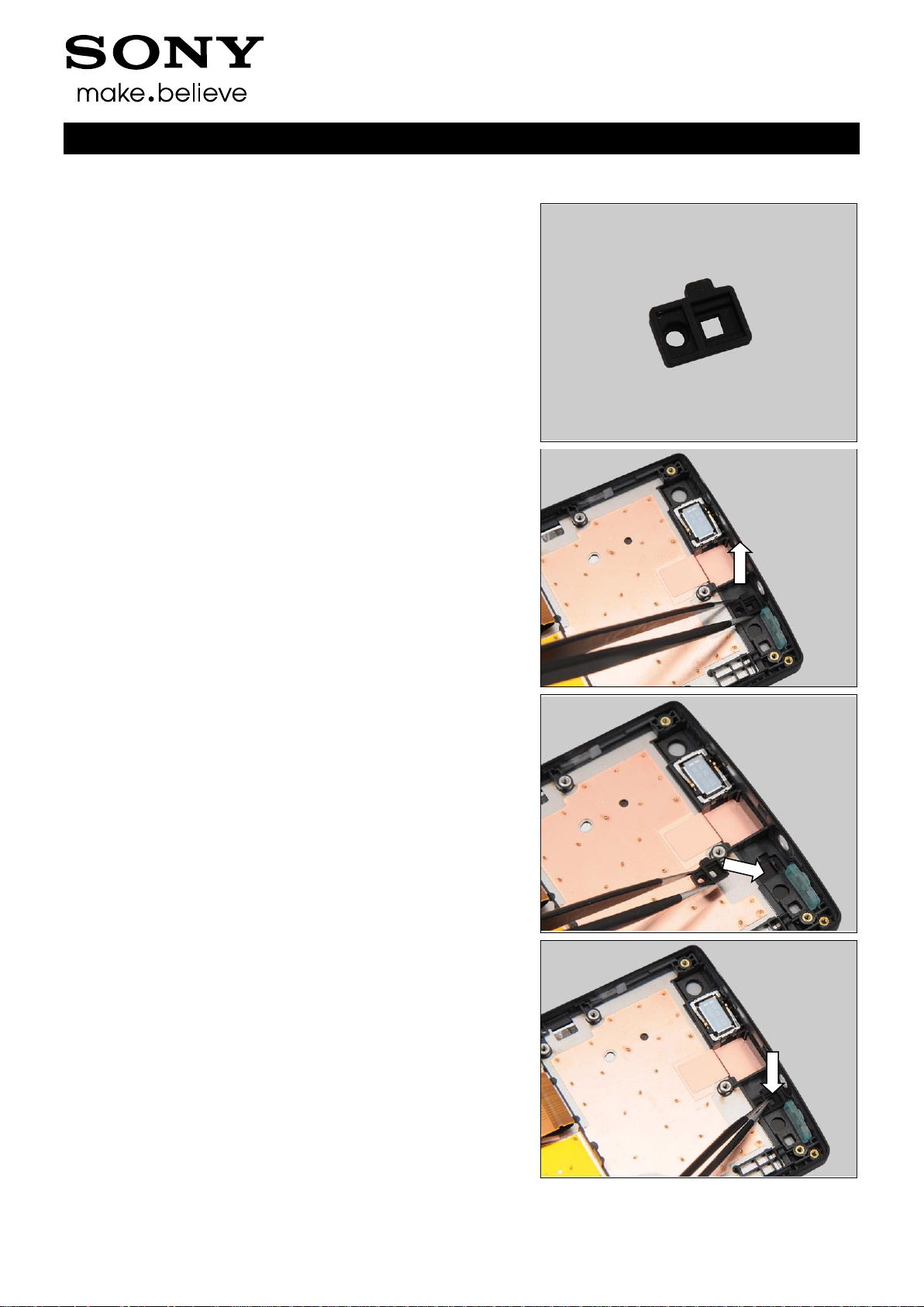
Follow the 3.1 – 3.6 Disassembly instructions!
Follow the 4.18 Removal instructions
Carry out the Removal as described below.
Prepare the new Ear Speaker.
Carry out the Installation as described below.
Follow the 4.18 Installation instructions
Follow the 5.2 – 5.7 Reassembly instructions!
REMOVAL
Insert the Flex Film Assembly Tool underneath and lift up to
detach the Ear Speaker.
Do not touch the contact pins!
Remove the Ear Speaker by using the Flex Film Assembly
Tool.
INSTALLATION
Clean the remained Cushion Receiver and place the new
Ear Speaker in the correct position.
Replacement
4.22 Ear Speaker
Working Instructions (mech)

1257-2928 Rev 4
Sony Mobile Communications AB – Company Internal
37(90)
Press to secure its attachment.
Replacement: Ear Speaker
Working Instructions (mech)

1257-2928 Rev 4
Sony Mobile Communications AB – Company Internal
38(90)
Follow the 3.1 – 3.4 Disassembly instructions!
Follow the 4.9 Removal instruction.
Carry out the Removal as described below.
Prepare the new Foil Adhesive Audio Jack.
Carry out the Installation as described below.
Follow the 4.9 Installation instruction.
Follow the 5.4 – 5.7 Reassembly instructions!
REMOVAL
Peel off the Foil Adhesive Audio Jack by using the
Tweezers.
Scrap! Not to be reused!
INSTALLATION
Place the new Foil Adhesive Audio Jack in the correct
position.
Press to secure its attachment.
Replacement
4.23 Foil Adhesive Audio Jack
Working Instructions (mech)

1257-2928 Rev 4
Sony Mobile Communications AB – Company Internal
39(90)
Peel off the protective film.
Replacement: Foil Adhesive Audio Jack
Working Instructions (mech)

1257-2928 Rev 4
Sony Mobile Communications AB – Company Internal
40(90)
Follow the 3.1 – 3.4 Disassembly instructions!
Follow the 4.8 Removal instruction.
Carry out the Removal as described below.
Prepare the new Foil Adhesive GPS Ant.
Carry out the Installation as described below.
Follow the 4.8 Installation instruction.
Follow the 5.4 – 5.7 Reassembly instructions!
REMOVAL
Peel off the Foil Adhesive GPS Ant by using the Tweezers.
Scrap! Not to be reused!
INSTALLATION
Place the new Foil Adhesive GPS Ant in the correct position.
Press to secure its attachment.
Replacement
4.24 Foil Adhesive GPS Ant
Working Instructions (mech)

1257-2928 Rev 4
Sony Mobile Communications AB – Company Internal
41(90)
Peel off the protective film.
Replacement: Foil Adhesive GPS Ant
Working Instructions (mech)

1257-2928 Rev 4
Sony Mobile Communications AB – Company Internal
42(90)
Follow the 3.1 – 3.4 Disassembly instructions!
Follow the 4.37 Removal instruction.
Carry out the Removal as described below.
Prepare the new Foil Adhesive NFC PBA.
Carry out the Installation as described below.
Follow the 4.37 Installation instruction.
Follow the 5.4 – 5.7 Reassembly instructions!
REMOVAL
Peel off the Foil Adhesive NFC PBA by using the Tweezers.
Scrap! Not to be reused!
INSTALLATION
Place the new Foil Adhesive NFC PBA in the correct
position as shown in the picture.
Press to secure its attachment.
Replacement
4.25 Foil Adhesive NFC PBA
Working Instructions (mech)

1257-2928 Rev 4
Sony Mobile Communications AB – Company Internal
43(90)
Peel off the protective film.
Replacement: Foil Adhesive NFC PBA
Working Instructions (mech)

1257-2928 Rev 4
Sony Mobile Communications AB – Company Internal
44(90)
Follow the 3.1 – 3.4 Disassembly instructions!
Follow the 4.33 Removal instructions.
Carry out the Removal as described below.
Prepare the new Foil Adhesive Speaker.
Carry out the Installation as described below.
Follow the 4.33 Installation instructions.
Follow the 5.4 – 5.7 Reassembly instructions!
REMOVAL
Peel off the Foil Adhesive Speaker by using the Tweezers.
Scrap! Not to be reused!
INSTALLATION
Place the new Foil Adhesive Speaker in the correct position.
Press to secure its attachment.
Replacement
4.26 Foil Adhesive Speaker
Working Instructions (mech)

1257-2928 Rev 4
Sony Mobile Communications AB – Company Internal
45(90)
Peel off the protective film.
Replacement: Foil Adhesive Speaker
Working Instructions (mech)

1257-2928 Rev 4
Sony Mobile Communications AB – Company Internal
46(90)
Follow the 3.1 – 3.7 Disassembly instructions!
Carry out the Removal as described below.
Prepare the new Foil Adhesive Speaker.
Carry out the Installation as described below.
Follow the 5.1 – 5.7 Reassembly instructions!
REMOVAL
Peel off the Foil Adhesive Transparent Front by using the
Tweezers.
Scrap! Not to be reused!
INSTALLATION
Place the new Foil Adhesive Transparent Front in the
correct position.
The holes must be aligned between the Foil Adhesive
Transparent Front and the Cover Transparent Assy!
Press to secure its attachment.
Replacement
4.27 Foil Adhesive Transparent Front
Working Instructions (mech)

1257-2928 Rev 4
Sony Mobile Communications AB – Company Internal
47(90)
Peel off the protective film.
Working Instructions (mech)
Replacement: Foil Adhesive Transparent Front

1257-2928 Rev 4
Sony Mobile Communications AB – Company Internal
48(90)
Follow the 3.1 – 3.6 Disassembly instructions!
Carry out the Removal as described below.
Prepare the new FPC Jack Assy.
Carry out the Installation as described below.
Follow the 5.2 – 5.7 Reassembly instructions!
REMOVAL
Insert the Flex Film Assembly Tool underneath and lift up to
detach the FPC Jack Assy.
Remove the FPC Jack Assy with your fingers.
INSTALLATION
Place the new FPC Jack Assy in the correct position.
Replacement
4.28 FPC Jack Assy
Working Instructions (mech)

1257-2928 Rev 4
Sony Mobile Communications AB – Company Internal
49(90)
Press to secure its position.
Do not touch the FPC area!
Replacement: FPC Jack Assy
Working Instructions (mech)

1257-2928 Rev 4
Sony Mobile Communications AB – Company Internal
50(90)
Follow the 3.1 – 3.7 Disassembly instructions!
Carry out the Removal as described below.
Prepare the new FPC Main Assy.
Carry out the Installation as described below.
Follow the 4.40 Installation instructions.
Follow the 5.1– 5.7 Reassembly instructions!
REMOVAL
Insert the Front Opening Tool to detach the key push switch
part on the FPC Main Assy.
Detach the FPC Main Assy by using the Flex Film Assembly
Tool.
Remove the FPC Main Assy with your fingers.
Scrap! Not to be reused!
Replacement
4.29 FPC Main Assy
Working Instructions (mech)

1257-2928 Rev 4
Sony Mobile Communications AB – Company Internal
51(90)
INSTALLATION
Place the new Sheet ACF Relay in the correct position.
Press to secure its attachment.
The guiding hole must be aligned accurately between
the Sheet ACF Relay and the PBA of the FPC Main Assy!
Peel off the protective film.
Pre-bend the FPC Main by the Guide line as shown in the
picture.
Replacement: FPC Main Assy
Working Instructions (mech)

1257-2928 Rev 4
Sony Mobile Communications AB – Company Internal
52(90)
Press to secure its attachment.
Place the new Sheet Relay FPC in the correct position
Press to secure its attachment.
Pre-bend the Sheet ACF Relay by the Guide line as shown
in the picture.
Replacement: FPC Main Assy
Working Instructions (mech)

1257-2928 Rev 4
Sony Mobile Communications AB – Company Internal
53(90)
Press the Sheet ACF Relay to secure its attachment.
Secure the FPC Main Assy in the correct position, by sliding
it under LCD FPC slot as shown in picture!
Press to secure key push switch part position by using the
Flex Film Assembly Tool.
Press along to secure the FPC Main attachment.
Replacement: FPC Main Assy
Working Instructions (mech)

1257-2928 Rev 4
Sony Mobile Communications AB – Company Internal
54(90)
Follow the 3.1 – 3.7 Disassembly instructions!
Follow the 4.29 Removal instructions!
Carry out the Removal as described below.
Prepare the new Key Camera.
Carry out the Installation as described below.
Follow the 4.29 Installation instructions!
Follow the 5.1 – 5.7 Reassembly instructions!
REMOVAL
Detach the Key Camera by using the Flex Film Assembly
Tool and remove it.
INSTALLATION
Place the new Key Camera with proper direction into the
slot.
Press to secure its position.
Replacement
4.30 Key Camera
Working Instructions (mech)

1257-2928 Rev 4
Sony Mobile Communications AB – Company Internal
55(90)
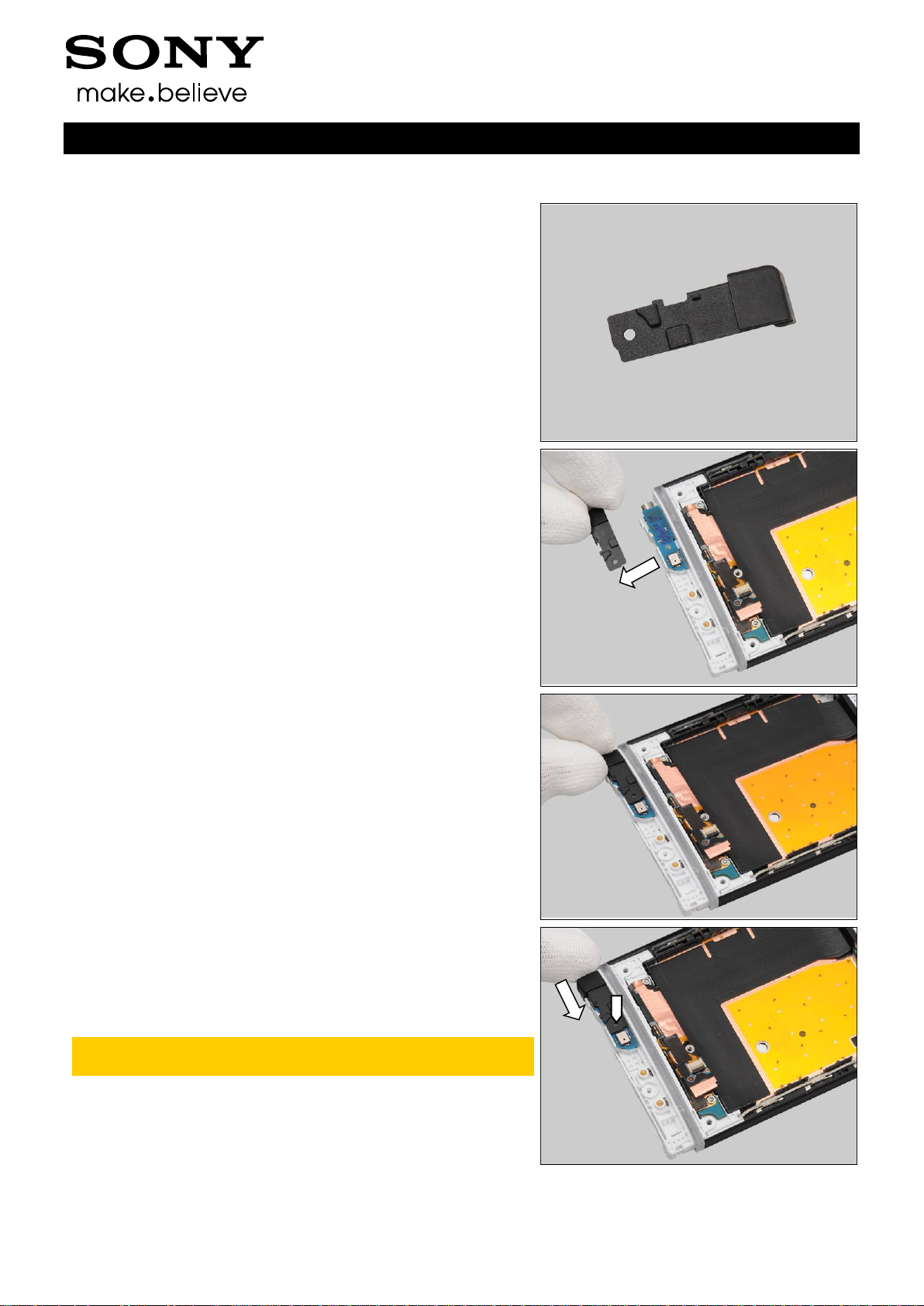
Follow the 3.1 – 3.6 Disassembly instructions!
Follow the 4.28 Removal instructions!
Carry out the Removal as described below.
Prepare the new Key On/Off.
Carry out the Installation as described below.
Follow the 4.28 Installation instructions!
Follow the 5.2 – 5.7 Reassembly instructions!
REMOVAL
Detach the Key On/Off by using the Flex Film Assembly
Tool and remove it.
INSTALLATION
Place the new Key On/Off with proper direction into the slot.
Press to secure its position.
Replacement
4.31 Key On/Off
Working Instructions (mech)

1257-2928 Rev 4
Sony Mobile Communications AB – Company Internal
56(90)
Follow the 3.1 – 3.7 Disassembly instructions!
Follow the 4.29 Removal instructions!
Carry out the Removal as described below.
Prepare the new Key Volume.
Carry out the Installation as described below.
Follow the 4.29 Installation instructions!
Follow the 5.1 – 5.7 Reassembly instructions!
REMOVAL
Detach the Key Volume by using the Flex Film Assembly
Tool and remove it.
INSTALLATION
Place the new Key Volume with proper direction into the
slot.
Press to secure its position.
Replacement
4.32 Key Volume
Working Instructions (mech)

1257-2928 Rev 4
Sony Mobile Communications AB – Company Internal
57(90)
Follow the 3.1 – 3.4 Disassembly instructions!
Follow the 4.26 Removal instructions!
Carry out the Removal as described below.
Prepare the new Loudspeaker.
Carry out the Installation as described below.
Follow the 4.26 Installation instructions!
Follow the 5.4 – 5.7 Reassembly instructions!
REMOVAL
Insert the Flex Film Assembly Tool underneath and lift up to
detach the Loudspeaker.
Scrap! Not to be reused!
Remove it by using the Flex Film Assembly Tool.
INSTALLATION
Clean the remained adhesive and place the new
Loudspeaker into its socket.
Replacement
4.33 Loudspeaker
Working Instructions (mech)

1257-2928 Rev 4
Sony Mobile Communications AB – Company Internal
58(90)
Press along the surface to secure its attachment.
Replacement: Loudspeaker
Working Instructions (mech)

1257-2928 Rev 4
Sony Mobile Communications AB – Company Internal
59(90)
Follow the 3.1 – 3.4 Disassembly instructions!
Carry out the Removal as described below.
Prepare the new Main Antenna.
Carry out the Installation as described below.
Follow the 5.4 – 5.7 Reassembly instructions!
REMOVAL
Remove the two screws Len:6.0 Diam:1.4M by Bits(JCIS No
0).
Insert the Guitar Pick to release the hooks of the Main
Antenna.
Remove the Main Antenna.
Replacement
4.34 Main Antenna
Working Instructions (mech)

1257-2928 Rev 4
Sony Mobile Communications AB – Company Internal
60(90)
INSTALLATION
Place the Main Antenna in the correct position and push to
lock the hooks of the Main Antenna.
Apply 10 Ncm torque when tightening the two Screw Len:6.0
Diam:1.4 with Bits (JCIS No 0).
Replacement: Main Antenna
Working Instructions (mech)

1257-2928 Rev 4
Sony Mobile Communications AB – Company Internal
61(90)
Follow the 3.1 – 3.4 Disassembly instructions!
Follow the 4.37 Removal instructions!
Carry out the Removal as described below.
Prepare the new NFC Antenna.
Carry out the Installation as described below.
Follow the 4.37 Installation instructions!
Follow the 5.4 – 5.7 Reassembly instructions!
REMOVAL
Peel off the NFC Antenna by using the Flex Film Assembly
Tool.
Scrap! Not to be reused!
INSTALLATION
Place the NFC Antenna in the correct position.
Pick up the new NFC Antenna with the upper green part
as shown in the picture!
Press to secure its attachment.
Replacement
4.35 NFC Antenna
Working Instructions (mech)

1257-2928 Rev 4
Sony Mobile Communications AB – Company Internal
62(90)
Follow the 3.1 – 3.4 Disassembly instructions!
Follow the 4.34, 4.13, 4.15 Removal instructions!
Carry out the Removal as described below.
Prepare the new PBA Bottom.
Carry out the Installation as described below.
Follow the 4.34, 4.13, 4.15, 4.21 Installation instructions!
Follow the 5.4 – 5.7 Reassembly instructions!
REMOVAL
Remove the PBA Bottom with your fingers.
INSTALLATION
Place the PBA Bottom in the correct position.
Press to secure its position.
The guiding hole must be aligned accurately between
the PBA Bottom and the Cover Transparent Assy!
Replacement
4.36 PBA Bottom
Working Instructions (mech)

1257-2928 Rev 4
Sony Mobile Communications AB – Company Internal
63(90)
Follow the 3.1 – 3.4 Disassembly instructions!
Follow 4.25 Removal Instructions!
Carry out the Removal as described below.
Prepare the new PBA NFC.
Follow the 4.41, 4.42, 4.25 Installation instructions
Carry out the Installation as described below.
Follow the 5.4 – 5.7 Reassembly instructions!
REMOVAL
Insert the Front Opening Tool to detach the PBA NFC.
Remove the PBA NFC with your fingers.
INSTALLATION
Place the PBA NFC in the correct position.
Replacement
4.37 PBA NFC
Working Instructions (mech)

1257-2928 Rev 4
Sony Mobile Communications AB – Company Internal
64(90)
Press to secure its position.
Replacement: PBA NFC
Working Instructions (mech)

1257-2928 Rev 4
Sony Mobile Communications AB – Company Internal
65(90)
Follow the 3.1 – 3.7 Disassembly instructions!
Carry out the Removal as described below.
Prepare the new RF Cable
Carry out the Installation as described below.
Follow the 5.1 – 5.7 Reassembly instructions!
REMOVAL
Release the RF Cable hooks by using the Flex Film
Assemble Tool.
INSTALLATION
Place the RF Cable into its socket.
Press to snap the hooks of the RF Cable by using the Flex
Film Assembly Tool.
Replacement
4.38 RF Cable
Working Instructions (mech)

1257-2928 Rev 4
Sony Mobile Communications AB – Company Internal
66(90)
Follow the 3.1 Disassembly instructions!
Carry out the Removal as described below.
Prepare the new Sheet GPS Ant
Carry out the Installation as described below.
Follow the 5.7 Reassembly instructions!
REMOVAL
Peel off the Sheet GPS Ant by using the Flex Film Assembly
Tool.
Scrap! Not to be reused!
INSTALLATION
Place the Sheet GPS Ant in the correct position.
Press to secure its attachment.
Replacement
4.39 Sheet GPS Ant
Working Instructions (mech)

1257-2928 Rev 4
Sony Mobile Communications AB – Company Internal
67(90)
Follow the 3.1 – 3.4 Disassembly instructions!
Carry out the Removal as described below.
Prepare the new Sheet LCD FPC.
Carry out the Installation as described below.
Follow the 5.4 – 5.7 Reassembly instructions!
REMOVAL
Unsnap the LCD BtB connectors by using the Front Opening
Tool.
Unsnap the touch panel BtB connectors by using the Front
Opening Tool.
Peel off the Sheet LCD FPC by using the Tweezers.
Scrap! Not to be reused!
Replacement
4.40 Sheet LCD FPC
Working Instructions (mech)

1257-2928 Rev 4
Sony Mobile Communications AB – Company Internal
68(90)
INSTALLATION
Place the new Sheet LCD FPC aligning the guiding line as
shown in the picture.
Press to secure its attachment.
Peel off the protective film.
Replacement: Sheet LCD FPC
Working Instructions (mech)

1257-2928 Rev 4
Sony Mobile Communications AB – Company Internal
69(90)
Follow the 3.1 – 3.4 Disassembly instructions!
Follow the 4.37 Removal instructions!
Carry out the Removal as described below.
Prepare the new Sheet NFC FPC.
Carry out the Installation as described below.
Follow the 4.37 Installation instructions!
Follow the 5.4 – 5.7 Reassembly instructions!
REMOVAL
Peel off the Sheet NFC FPC by using the Tweezers.
Scrap! Not to be reused!
INSTALLATION
Place the new Sheet NFC FPC in the correct position.
Press to secure its attachment.
Replacement
4.41 Sheet NFC FPC
Working Instructions (mech)

1257-2928 Rev 4
Sony Mobile Communications AB – Company Internal
70(90)
Follow the 3.1 – 3.4 Disassembly instructions!
Follow the 4.37 Removal instructions!
Carry out the Removal as described below.
Prepare the new Sheet NFC Shield.
Carry out the Installation as described below.
Follow the 4.37 Installation instructions!
Follow the 5.4 – 5.7 Reassembly instructions!
REMOVAL
Peel off the Sheet NFC Shield by using the Tweezers.
Scrap! Not to be reused!
INSTALLATION
Place the new Sheet NFC Shield in the correct position.
Press to secure its attachment.
Replacement
4.42 Sheet NFC Shield
Working Instructions (mech)

1257-2928 Rev 4
Sony Mobile Communications AB – Company Internal
71(90)
Peel off the protective film.
Replacement: Sheet NFC Shield
Working Instructions (mech)

1257-2928 Rev 4
Sony Mobile Communications AB – Company Internal
72(90)
Carry out the Removal as described below.
Prepare the new Sheet Protection LCD.
Carry out the Installation as described below.
REMOVAL
Peel off the Sheet Protection LCD with your fingers.
Scrap! Not to be reused!
INSTALLATION
Place the Sheet Protection LCD in the correct position.
Press to secure its attachment.
Replacement
4.43 Sheet Protection LCD
Working Instructions (mech)

1257-2928 Rev 4
Sony Mobile Communications AB – Company Internal
73(90)
Follow the 3.1 – 3.6 Disassembly instructions!
Carry out the Removal as described below.
Prepare the new Shield Can BB A.
Carry out the Installation as described below.
Follow the 5.2 – 5.7 Reassembly instructions!
REMOVAL
Insert the Tweezers into the corners of the Shield Can BB A
and pull upwards to release it.
Scrap! Not to be reused!
Remove the Shield Can BB A.
INSTALLATION
Place the new Shield Can BB A and press gently until it is
securely attached.
Replacement
4.44 Shield Can BB A
Working Instructions (mech)

1257-2928 Rev 4
Sony Mobile Communications AB – Company Internal
74(90)
Follow the 3.1 – 3.6 Disassembly instructions!
Carry out the Removal as described below.
Prepare the new Shield Can BB B.
Carry out the Installation as described below.
Follow the 5.2 – 5.7 Reassembly instructions!
REMOVAL
Insert the tweezers into the corners of the Shield Can BB B
and pull upwards to release it.
Scrap! Not to be reused!
Remove the Shield Can BB B.
INSTALLATION
Place the new Shield Can BB B and press gently until it is
securely attached.
Replacement
4.45 Shield Can BB B
Working Instructions (mech)

1257-2928 Rev 4
Sony Mobile Communications AB – Company Internal
75(90)
Follow the 3.1 – 3.6 Disassembly instructions!
Carry out the Removal as described below.
Prepare the new Shield Can Lid Non Cell.
Carry out the Installation as described below.
Follow the 5.2 – 5.7 Reassembly instructions!
REMOVAL
Insert the tweezers into the corners of the Shield Can Lid
Non Cell and pull upwards to release it.
Scrap! Not to be reused!
Remove the Shield Can Lid Non Cell.
INSTALLATION
Place the new Shield Can Lid Non Cell and press gently
until it is securely attached.
Replacement
4.46 Shield Can Lid Non Cell
Working Instructions (mech)

1257-2928 Rev 4
Sony Mobile Communications AB – Company Internal
76(90)
Follow the 3.1 – 3.6 Disassembly instructions!
Carry out the Removal as described below.
Prepare the new Shield Can RF.
Carry out the Installation as described below.
Follow the 5.2 – 5.7 Reassembly instructions!
REMOVAL
Insert the tweezers into the corners of the Shield Can RF
and pull upwards to release it.
Scrap! Not to be reused!
Remove the Shield Can RF.
INSTALLATION
Place the new Shield Can RF and press gently until it is
securely attached.
Replacement
4.47 Shield Can RF
Working Instructions (mech)

1257-2928 Rev 4
Sony Mobile Communications AB – Company Internal
77(90)
Follow the 3.1 – 3.4 Disassembly instructions!
Carry out the Removal as described below.
Prepare the new Water Indicator.
Carry out the Installation as described below.
Follow the 5.4 – 5.7 Reassembly instructions!
REMOVAL
Peel off the Water Indicator by using the Flex Film Assembly
Tool.
Scrap! Not to be reused!
INSTALLATION
Place the new Water Indicator in the correct position.
Press to secure its attachment.
Replacement
4.48 Water Indicator
Working Instructions (mech)

1257-2928 Rev 4
Sony Mobile Communications AB – Company Internal
78(90)
Follow the 3.1 – 3.4 Disassembly instructions!
Carry out the Removal as described below.
Prepare the new Water Indicator L.
Carry out the Installation as described below.
Follow the 5.4 – 5.7 Reassembly instructions!
REMOVAL
Peel off the Water Indicator L by using the Flex Film
Assembly Tool.
Scrap! Not to be reused!
INSTALLATION
Place the new Water Indicator L in the correct position.
Press to secure its attachment.
Replacement
4.49 Water Indicator L
Working Instructions (mech)

1257-2928 Rev 4
Sony Mobile Communications AB – Company Internal
79(90)
Follow the 3.1 – 3.6 Disassembly instructions!
Replace the Swap Board.
Follow the 4.18 Installation instructions!
Follow the 5.2 – 5.7 Reassembly instructions!
Press the On/Off key to power on the phone, wait the phone
booting up on a table.
Please DO NOT move the phone during starting up until
“Select Language” menu is shown on the display!
After “Select Language” menu, turn off the phone.
4.51 Board Swap – Change Label
CHANGE LABEL
Follow the instructions in the Generic Repair Manual –
Build swap for change of label.
Replacement
4.50 Board Swap - Replacement
Working Instructions (mech)

1257-2928 Rev 4
Sony Mobile Communications AB – Company Internal
80(90)
The reassembly is done in the following order:
1. Cover Front Assy
2. Cover Transparent Assy
3. Main PBA
4. Main Camera
5. Rear Frame Assy
6. Battery
7. Cover Bottom
8. Cover Rear Assy
5.1 Cover Front Assy &
Cover Transparent Assy
Prepare the Cover Transparent Assy and the Cover Front
Assy.
Put the sub PBA of the Main FPC on the Cover Transparent
Assy.
The hole must be aligned accurately between the sub
PBA of the Main FPC and the Cover Transparent Assy!
Apply 10 Ncm torque when tightening the one Screw
Len:2.0 Diam:1.4 M with Bits (JCIS No 0).
5 Reassembly
Working Instructions (mech)

1257-2928 Rev 4
Sony Mobile Communications AB – Company Internal
81(90)
Reassembly
Turn over the Cover Transparent Assy gently.
Put the RF cable into the socket on the Cover Transparent
Assy and press to secure its position.
Connect one end of the RF Cable with the Flex Film
Assembly Tool.
Turn over the Cover Transparent Assy gently and secure the
Cover Transparent Assy into its sockets.
Working Instructions (mech)

1257-2928 Rev 4
Sony Mobile Communications AB – Company Internal
82(90)
Reassembly
Press the Cover Transparent Assy to secure its position
gently.
Apply 12 Ncm +/-1Ncm torque when tightening the two
Screw Len:3.5 Diam:1.4 with Bits (JCIS No 0).
Connect the touch panel BtB connector with fingers.
Connect the LCD BtB connector with fingers.
Working Instructions (mech)

1257-2928 Rev 4
Sony Mobile Communications AB – Company Internal
83(90)
Reassembly
Make sure the three parts are secured as shown in the
picture!
5.2 Main PBA
Connect one end of the RF Cable by using the Flex Film
Assembly Tool.
Turn over the main PBA and place the main PBA into its
socket.
Press the main PBA to secure its position gently.
Note: Do not push down the Main FPC and FPC Jack
Assy BtB connectors under the main PBA!
Working Instructions (mech)

1257-2928 Rev 4
Sony Mobile Communications AB – Company Internal
84(90)
Reassembly
Connect the Main FPC BtB connector with fingers.
Connect the FPC Jack Assy BtB connector with fingers.
5.3 Main Camera
Place the Main Camera into its socket with 30 degree tilt
with fingers.
Press to secure its position gently.
Working Instructions (mech)

1257-2928 Rev 4
Sony Mobile Communications AB – Company Internal
85(90)
Reassembly
Connect the Main Camera BtB connectors with fingers.
5.4 Rear Frame Assy
Prepare the Rear Frame Assy and the Unit.
Connect the NFC BtB connector with fingers.
5.5 Battery
Raise the right side of the Rear Frame approximately
60°from the right side.
Do not draw the NFC FPC more than 60°!
Working Instructions (mech)

1257-2928 Rev 4
Sony Mobile Communications AB – Company Internal
86(90)
Reassembly
Place the Battery into its socket.
Press to secure its position.
Put the Rear Frame Assy in place.
Press to snap the hooks.
Working Instructions (mech)

1257-2928 Rev 4
Sony Mobile Communications AB – Company Internal
87(90)
Reassembly
Apply 10 Ncm torque when tightening the three screws
Len:3.5 Diam:1.4M with Bits (JCIS No 0).
Apply 12 Ncm torque when tightening the seven Screw
Len:3.5 Diam:1.4 with T5.
5.6 Cover Bottom
Place the Cover Bottom on the Cover Transparent Assy.
Push to Snap the Cover Bottom.
Working Instructions (mech)

1257-2928 Rev 4
Sony Mobile Communications AB – Company Internal
88(90)
Reassembly
5.7 Cover Rear Assy
Place the Cover Battery.
Push to snap the Cover Rear Assy.
Press to snap the Cover Rear Assy.
Working Instructions (mech)

1257-2928 Rev 4
Sony Mobile Communications AB – Company Internal
89(90)
Below is a link to a list of countries of origin. If you are printing a Brazil or VIVO label, scan the
barcode corresponding to the correct country of origin for the “Fabricado” field.
Working Instructions (mech)
6 Country of Origin Barcodes for
Brazil/VIVO Labels

1257-2928 Rev 4
Sony Mobile Communications AB – Company Internal
90(90)
Rev.
Date
Changes / Comments
1
2012-Mar-2
Initial release
2
2012-Mar-6
Update Main Antenna replacement and template
3
2012-Mar-6
No change
4
2012-Mar-26
Update Cap USB replacement
7 Revision History
Working Instructions (mech)

1257-2932 Rev 2
Sony Mobile Communications AB – Company Internal
Repair Movies
- mechanical -
Xperia S
LT26i, SO-02D

1257-2932 Rev 2
Sony Mobile Communications AB – Company Internal
2(4)
Repair Movies (mech)
CONTENTS
1 Movies ............................................................................................. 3
1.1 Disassembly ......................................................................................... 3
1.2 Reassembly .......................................................................................... 3
2 Revision History ............................................................................. 4
To view the embedded repair movies in this document, Acrobat Reader version 8 (or later) and
Flash Player version 8 (or later) must be installed on your computer.
For best picture quality, select “Actual size” or “100%” as zoom level in Acrobat Reader.
To magnify while keeping an acceptable picture quality, increase the zoom level to 200%.
If the movies appear to be jerky or blurred when viewing on-line, this is probably caused by the
connection speed being too slow.
In that case, right-click with the mouse on the document name and select Save Target As to
download the repair movie document for off-line viewing.
For general information about repair movies, refer to
1220-1333: Generic Repair Manual - mechanical

1257-2932 Rev 2
Sony Mobile Communications AB – Company Internal
3(4)
1.1 Disassembly
1. Cover Rear Assy
2. Cover Bottom
3. Battery
4. Rear Frame Assy
5. Main Camera
6. Main PBA
7. Cover Transparent Assy
8. Cover Front Assy
1.2 Reassembly
1. Cover Front Assy
2. Cover Transparent Assy
3. Main PBA
4. Main Camera
5. Rear Frame Assy
6. Battery
7. Cover Bottom
8. Cover Rear Assy
1 Movies
Repair Movies (mech)

1257-2932 Rev 2
Sony Mobile Communications AB – Company Internal
4(4)
Rev.
Date
Changes / Comments
1
2012-Mar-2
Initial release
2
2012-Mar-7
Template update
2 Revision History
Repair Movies (mech)
 Loading...