

Page 1
Installation + User Guide
SNYSC1 Sony Compatible
SiriusConnect™ Interface
Page 2
Congratulations on the Purchase of your new SNYSC1
Sony Compatible SiriusConnect Interface
The SNYSC1 is a specia lly designed interface that allows a Sony® SAT-Radio Ready
headunit to correctly communicate and control a SIRIUS® Satellite Radio Tuner .
The SNYSC1 is compatib le with all Sony SAT-Radio-Ready headunits. It can be connected to either the S CC1 SiriusConnect Vehicle Tuner or the SCVDOC1 SiriusConnect Vehicle Dock with a compatible Dock and Play or portable SIRIUS radio attached.
Reguires Sony
SAT-Radio-Ready H eadunit...
...and a SiriusCo nnect tuner ( SCC1) or a
vehicle kit (SCVD OC1) and comp atible
Dock and Play or Portable radi o
Page 3

Table of Contents
TABLE OF CONTENTS . . . . . . . . . . . . . . . . . . . . . . . . . . . 3
COPYRIGHTS & TRADEMARKS . . . . . . . . . . . . . . . . . . . . . .4
WARNING AND SAFETY INFORMATION . . . . . . . . . . . . . . . . . . . 5
FCC Information . . . . . . . . . . . . . . . . . . . . . . . . . . . . 5
Canadian Compliance . . . . . . . . . . . . . . . . . . . . . . . . . . 6
Safety Precautions . . . . . . . . . . . . . . . . . . . . . . . . . . . . 6
PACKAGE CONTENTS . . . . . . . . . . . . . . . . . . . . . . . . . . . 7
COMPATIBILITY . . . . . . . . . . . . . . . . . . . . . . . . . . . . . 9
CONNECTORS . . . . . . . . . . . . . . . . . . . . . . . . . . . . . 10
INSTALLATION . . . . . . . . . . . . . . . . . . . . . . . . . . . . . 12
Mounting the SNYSC1 Interface . . . . . . . . . . . . . . . . . . . . . . 12
Wiring the SNYSC1 Interface . . . . . . . . . . . . . . . . . . . . . . . 15
OPERATION . . . . . . . . . . . . . . . . . . . . . . . . . . . . . . 20
SPECIFICATIONS . . . . . . . . . . . . . . . . . . . . . . . . . . . . 21
[ Tabl e of Con tent s ]
3
Page 4

Copyrights & Trademarks
© 2007 Sirius Satellit e Radio Inc. All Rights Reserved.
® “SIRIUS”, the SIRIUS dog logo, channel names and logos are trademarks of Sirius
Satellite Radio Inc. “ Sony” is a registered trademark of Sony Electronics Inc. “iPod” is
a registered trademark of Apple Inc. All Rights Reserved.
™ “SiriusConnect”, is a trademark of Sirius Satellite Radio Inc. UniLink is a trademark
of Sony Electronics In c.
Hardware, subscription , and activation fee required. For full Terms & Conditions, visit
http://sirius.com. Pri ces an d programming are subject to change. Not available in HI
and AK. Equipment and subscription sold separately. Installation required with some
equipment.
[ Copy righ ts & Tra demarks ]
4
Page 5

Warning and Safety Information
FCC Information
This device complies w ith part 15 of the FCC Rules. Operation is subject to the following two conditions:
This device may not ca use harmful interference, and
1.
This device must accep t any interference received, including interference that
2.
may cause undesired op eration.
Note: This equipment h as been tested and found to comply with the limits for
a CLASS B digital devi ce, pursuant to Part 15 of the FCC Rules. These limits
are designed to provid e reasonable protection against harmful interference
when the equipment is operated in a commercial environment. This equipment
generates, uses, and c an radiate radio frequency energy and, if not installed
and used in accordance with the instructions, may cause harmful interference
to radio communication s. However, there is no guarantee that interference will
not occur in a particu lar installation. If this equipment does cause harmful interference to radio or televisi on rec eption , which can be determined by turning the
equipment off and on, the user is encouraged to try to correct the interference
by one or more of the following measures:
Reorient or relocate t he receiving antenna.
1.
Increase the separatio n between the equipment and the receiver.
2.
Connect the equipment into an outlet on a circuit different from that to
3.
which the receiver is connected.
Consult the dealer or an experienced radio/TV technician for help.
4.
WARN ING
Changes or modificatio ns not expressly approved by the manufacturer could void the
user’s authority to op erate the equipment.
[ Warn ing and Safe ty Informat ion ]
5
Page 6

Canadian Compliance
This Class B digital a pparatus complies with Canadian ICES-003.
Cet appareil numérique de la classe B est conforme à la norme NMB-003 du Canada.
Safety Precautions
Be sure to observe the following warnings. Failure to follow these safety instructions
and warnings may resul t in a serious accident and/or personal injury.
Install the cables and wiring so that it is not crimped or pinched by screws or
•
sharp metal edges. Rou te the cables away from moving parts or sharp pointed
edges. This will preve nt crimping and damage to the wiring. If the wiring must pass
through a metal hole, be sure to use a rubber grommet to prevent the wire’s insulation from being cut by the metal edge of the hole.
Do not open, disassemb le or alter the unit in any way. Doing so may result in fire,
•
electric shock or prod uct damage.
Do not insert any obje cts into the unit. Doing so may result in fire, electric shock or
•
product damage.
Do not install the uni t to high levels of humidity, moisture or dust. Doing so can
•
result in electric sho ck or product failure.
[ Warn ing and Safe ty Informat ion ]
6
Page 7
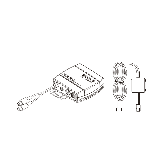
Package Contents
The following items ar e included with your purchase of the SNYSC1. Unpack the materials carefully and make sure that everything shown is present. If anything is missing
or damaged, or if the device fails to operate properly, notify your dealer immediately. It
is recommended that yo u retain the original carton and packing materials in case you
need to ship your kit in the future.
SNYSC 1 SiriusC onnect In terface A dapterSNYSC 1 SiriusC onnect In terface A dapter
Power HarnessPower Harness
[ Pack age Cont ents ]
7
Page 8
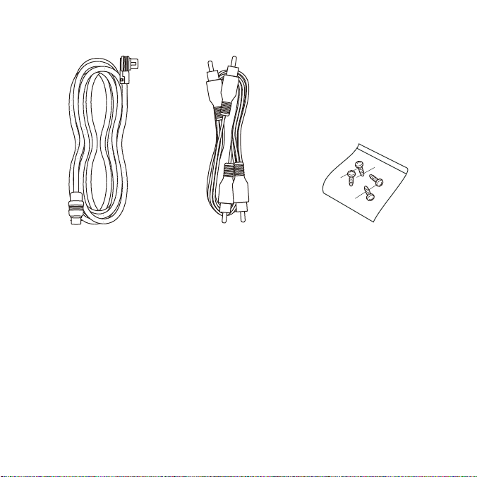
UniLi nk™ Data CableUniLi nk™ Data Cable
[ Pack age Cont ents ]
8
Audio CableAudio Cable Mount ing screw s (x4)Mount ing screw s (x4)
Page 9

Compatibility
The SNYSC1 SiriusConne ct Interface is compatible with all Sony SAT-Radio-Ready
headunits.
The UniLink input pass -through connector on the SNYSC1 can support the Sony
iPOD adapter or Sony C D Changer.
[ Comp atib ilit y ]
9
Page 10

UNILINK INAUDIO IN
AUDIO IN
L/R
AUDIO
OUT L/R
UNILINK
IN
SC
INPUT
L R
SC INPUT
AUDIO
OUT
UNILINK OUT POWER
UNILINK
OUT POWER
Figur e 1Figur e 1
Connectors
Figure 1 and the table following identify and describe the connectors of the SNYSC1.
Desc riptio n of t he SNY SC1 Connectors
Conn ector Desc riptio n
Audi o In C onnect ors L/ R
UniL ink In Conne ctor
Audi o Out Cable
10
[ Conn ecto rs ]
Connects to the audio output of a Sony CD Changer,
iPod adapter, or other UniLink compatible device
Connects to a Sony CD Changer, iPod® adapter, or
other UniLink compatib le device
Connects to the UniLin k Audio input on the Sony
headunit
Page 11

Desc riptio n of t he SNY SC1 Connectors
Conn ector Desc riptio n
SC I nput C onnect or
UniL ink Ou t Conn ector
Powe r Conn ector
Connects to the SCC1 t uner or the SCVDOC1 dock
Connects to the UniLin k connector on the Sony
headunit
Connects to the vehicl e’s DC power/ground using the
provided power harness
Yellow: Connects to a positive DC voltage source
Black: Connects to veh icle ground
[ Conn ecto rs ]
11
Page 12

Installation
It is recommended that prior to starting the installation, you thoroughly read these
installation instructi ons and then follow them carefully for a successful installation.
Mounting the SNYSC1 Interface
Consider the mounting location carefully. You should make sure that you avoid the
following:
Any location where the device is exposed to moisture.
•
Any location where the device is exposed to extreme heat.
•
Any location where the device cannot get adequate ventilation.
•
Any location that would interfere with moving parts on the vehicle or hamper driving.
•
Be sure that you find a mounting location that is flat and has clearance above the
device to prevent any damage as well as allowing for ventilation.
The SNYSC1 can be moun ted in three different ways:
By using attached moun ting plate with the provided screws to secure the device
1.
to the vehicle. (Figur e 2) C aution: If you are attaching the device directly to the
vehicle’s chassis, be sure that you check to make sure the area behind the device
is free from moving pa rts, fuel or brake lines, wire harnesses, or any other items
which may get damaged by drilling a mounting hole or using the supplied screws.
By removing the mounti ng plate from the SNYSC1, and instead mounting it
2.
directly to a surface using either double-sided stick tape, hook and loop, or other
adhesive material (not provided). Simply remove the two screws on the bottom of
the SNYSC1 to remove t he bracket, as shown in Figure 3.
[ Inst alla tion ]
12
Page 13

By attaching the SNYSC 1 and the SIRIUS SCC1 tuner together. To connect the
Figur e 2Figur e 2
Figur e 3Figur e 3
3.
devices together, simp ly remove the mounting brackets from each device, rotate
them 90°, and connect them together as shown in Figure 4.
[ Inst alla tion ]
13
Page 14

Figur e 4Figur e 4
14
[ Inst alla tion ]
Page 15

Wiring the SNYSC1 Interface
BATTERY
Powe r Filte r
with Fuse
2A AGC Type Fuse
Batt ery 12 VDC
No C onnecti on
GND
No C onnecti on
Powe r Conne ctor
(As Viewed F rom the Wire E nd of t he Plug )
BATT (Yello w)
GND
(Blac k)
Figur e 5Figur e 5
Powe r Harness
Connect the yellow wir e of the power harness to a suitable +12V power source in the
vehicle, which is capa ble of providing 1 amp of power. Connect the black wire to the
vehicle ground. (Figur e 5)
The power harness for the SNYSC1 has power filter box which contains a fuse for the
12V battery connection . Figure 5 also shows the location and type of fuse, and also
the identifies the pin -outs of the power connector.
[ Inst alla tion ]
15
Page 16

Syst em Wiring
There are three possib le wiring configurations:
A simple configuration which utilizes only the SNYSC1 Interface. (Figure 6 on
1.
page 17.)
A configuration which utilizes an iPod adapter in addition to the SNYSC1 Inter-
2.
face. (Figure 7 on pag e 18.)
A configuration which utilizes an iPod adapter and a CD changer in addition
3.
to the SNYSC1 Interfac e. (Figure 8 on page 19.) This configuration requires a
Sony XA-C40 Source Sel ector (not provided). Please note that it is important to
connect each device to the correct input ports of the source selector, as shown
in Figure 8.
[ Inst alla tion ]
16
Page 17

Sony Headunit
SIRIUS
SNYSC1
SIRIUS
SCVDOC1
SIRIUS
SCC1
OR
UNILINK OUT
UNILINK IN
AUDIO OUT
AUDIO IN
POWERSC INPUT
ANTENNASC OUTPUT
Figur e 6Figur e 6
[ Inst alla tion ]
17
Page 18

Sony Headunit
SIRIUS
SNYSC1
SIRIUS
SCVDOC1
SIRIUS
SCC1
OR
UNILINK OUT
UNILINK IN
AUDIO OUT
AUDIO IN
POWERSC INPUT
ANTENNASC OUTPUT
Sony XA-110IP
iPod Adapter
Figur e 7Figur e 7
18
[ Inst alla tion ]
Page 19

3
1
2
Sony XA-110IP
iPod Adapter
Sony Headunit
Sony CD Changer
SIRIUS
SNYSC1
SIRIUS
SCVDOC1
SIRIUS
SCC1
OR
Sony XA-C40
Source
Selector
Connecting the UniLink Cables:
When using a Sony Source Selector
such as the XA-C40 or XA-300, it is
important to connect the devices to the
correct UniLink inputs on the source
selector:
Input 1 = SIRIUS SNYSC1
Input 2 = Sony XA-110IP iPod Adapter
Input 3 = Sony CD Changer
UNILINK OUT
UNILINK IN
AUDIO OUT
AUDIO IN
POWERSC INPUT
ANTENNASC OUTPUT
Figur e 8Figur e 8
[ Inst alla tion ]
19
Page 20

Operation
For operation instruct ions, please consult the instruction manual which accompanied
your headunit.
Additional instruction s may also be found in the manual which accompanied your
SIRIUS SCC1 tuner or S CVDOC1 dock and SIRIUS radio.
[ Oper atio n ]
20
Page 21

Specifications
Power Requirements . . . . . . . . . . . . . . . . . . . . . . . . . . . . . . . . . . . . . . . . 11- 14 VDC, 1A
In-Line fuse (Located inside Filter Box) . . . . . . . . . . . . . . . . . . . . . . . . . . . . . . . . 1A AGC
Operation Temperature . . . . . . . . . . . . . . . . . . . . . . . . . -20° to +85° C (-4° to +185° F)
Dock Dimensions (Width x Height x Depth) . . . . . . . . . . . . . . 86 mm x 87mm x 33.2mm
Weight . . . . . . . . . . . . . . . . . . . . . . . . . . . . . . . . . . . . . . . . . . . . . . . . . . . . . . . . . . . 120g
UniLink Cable Length . . . . . . . . . . . . . . . . . . . . . . . . . . . . . . . . . . . . . . . . . . . . . . . . . 2.5m
RCA Audio Cable Length . . . . . . . . . . . . . . . . . . . . . . . . . . . . . . . . . . . . . . . . . . . . . .2.5m
[ Spec ific atio ns ]
21
Page 22

Page 23

Page 24

sirius.com
SIRIUS Satellite Radio Inc.
1221 Avenue of the Americas
New York, NY 10020
800.869.5590
SNYSC1 SiriusConnect™ Interface (SNYSC1120407a)
OO.ABCD1.001
 Loading...