

Page 1
4-696-253-11(1)
Network Camera
Installation Manual
Before operating the unit, please read this manual thoroughly and
retain it for future reference.
C
D
85.7 (3 3/8)
Caution
Take care not to trap the cables between the camera and the ceiling or the wall. If
the cable is trapped, it may cause a fire or electric shock due to breaking.
Inside
Items and are not supported for SNC-EM641.
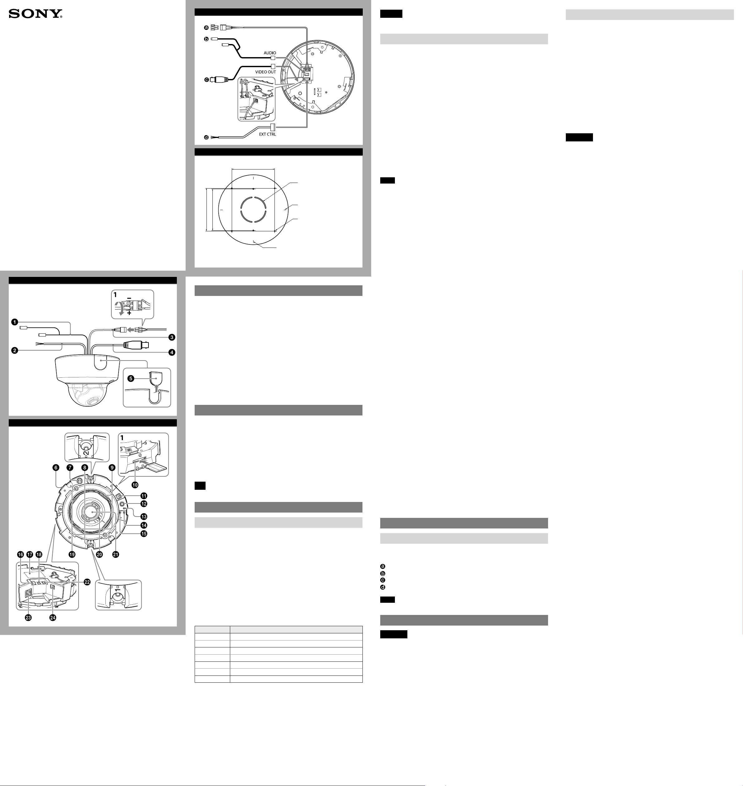
Camera unit
MONITOR output jack
Connect this jack to a video input connector of a video monitor. You can adjust
the camera or lens while looking at the image on the video monitor. After
adjusting the camera or lens, disconnect the cable.
Camera unit mounting screws (2 positions)
Make sure to tighten the screws securely when installing the camera.
Camera head fixing screw (tilt)
Firstly, loosen the screw and point the camera head in the desired direction, then
tighten the screw to secure in place.
SD card slot
This slot is used for optional SD memory cards.
Image data in the camera can be recorded to a memory card by inserting it into
the slot.
When inserting, point the contact area at the rating label side (referring to the
illustration), and be sure to insert it completely. (-1)
This unit is only compatible with SD and SDHC memory cards.
Deciding the Installation Location of the Camera
After deciding the direction in which the camera will shoot, make the required
hole (ø 50 mm (2 inches)) for the connecting cables using the supplied template.
Then decide the two or four mounting hole positions to install the bracket.
Mounting screws
The supplied bracket is provided with ø 4.5 mm (3/16 inch) mounting holes. Install
the bracket on a ceiling or wall with screws through two or four mounting holes:
two 83.5 mm (3 9/32 inches)-pitched holes or four 85.7 mm (3 3/8 inches)-pitched
holes. The required mounting screws differ depending on the installation location
and its material. Use commercially-available screws.
Steel wall or ceiling: Use M4 bolts and nuts. (Hexagon head bolt should not be
used.)
Wooden wall or ceiling: Use M4 tapping screws. The panel thickness must be
15 mm (5/8 inch) or more.
Concrete wall: Use anchors, bolts and plugs suitable for concrete walls. (Head
shape of M4 bolt: Pan head screw or hexagon head bolt should not be used.)
Junction box: Use screws to match the holes on the junction box. (Head shape
of screw: ø 7 mm (9/32 inch) Height 4 mm (3/16 inch) or less)
WARNING
The required mounting screws differ depending on the installation location and
its material. If you do not secure the camera with the appropriate mounting
screws, the camera may fall off.
SNC-VM641/EM641
© 2017 Sony Corporation
A
B
Hole for connecting cables
ø50 (2)
/8)
/32)
3
9
85.7 (3
83.5 (3
Vertical mark
Horizontal mark
Hole for installing the
bracket
Unit: mm (inches)
About the Manuals
Safety Regulations (included)
The Safety Regulations describes notes for the secure usage of camera. Be sure
to read it.
Installation Manual (this document)
Describes the names and functions of parts and controls of the Network Camera,
gives connection examples and explains how to set up the camera. Be sure to
read the Installation Manual before operating.
The illustration of SNC-VM641 is used for example purpose.
An I/O cable or power input cable is not supplied for SNC-EM641.
Electronic Instruction Manual (Web)
How to control the camera via a web browser ˎ
How to setup the camera ˎ
Operate the camera referring to the guide above after having installed and
connected the camera properly based on the Installation Manual.
Assigning the IP address
1 Download the installer for “SNC toolbox” to a folder from the download
site.
2 Install the SNC toolbox.
Unzip the ZIP file of the downloaded installer.
Double-click “SncToolbox_Setup.exe.” For details on installing and use refer to
the Application Guide.
3 Assign an IP address.
Assign an IP address using the installed SNC toolbox. For details, see “Using
SNC toolbox” – “Assign an IP address” in the Application Guide.
Tip
SNC toolbox stands for Sony Network Camera toolbox.
Location and Function of Part
Note
For inquiries regarding verified SD memory cards, contact your authorized Sony
dealer.
NTSC/PAL switch
Switching the video output.
After setting the switch, reboot the camera unit.
ZOOM/FOCUS switch
Use this switch to adjust lens’ zoom and focus. Slide the switch lever to select the
desired function.
[W] WIDE: Zoom out
[T] TELE: Zoom in
[N] NEAR: Focus on a nearby subject
[F] FAR: Focus on a distant subject
Hold down the center of the ZOOM/FOCUS switch for a moment to focus
automatically.
Reset switch
To reset the camera to the factory default settings, hold down this switch with a
point and supply the power to the camera.
NETWORK indicator (Green/Orange)
The indicator lights up or flashes when the camera is connected to the network.
The indicator is off when the camera is not connected to the network.
POWER indicator (Green)
When the power is supplied to the camera, the camera starts checking the
system. If the system is normal, this indicator lights up.
AC / DC IN (power input) connector (SNC-VM641 only)
Connect the supplied power input cable to this connector.
Rating Label
This label shows the name of device and its electric rating.
AUDIO connector
Connect the supplied audio cable to this connector.
Camera head fixing screw (pan)
Firstly, loosen the screw and point the camera head in the desired direction, then
tighten the screw to secure in place.
mark
Indicates the image direction.
Lens
EXT CTRL (external control input/output) connector (SNC-VM641
only)
Connect the supplied I/O cable to this connector.
LAN network port (RJ-45)
Connect a network cable (UTP, category 5) to this port to communicate with a
network or PoE* system.
For details on connection, see the Instruction Manual of the power supply
equipment.
(*PoE stands for Power over Ethernet. It is pursuant to IEEE802.3af.)
VIDEO OUT (video output) connector
Connect the supplied BNC cable to this connector.
Side
The cables below are not connected when the unit comes from the factory.
SNC-VM641: , , ,
SNC-EM641: ,
Audio cable (supplied)
The connector with the longer cable (SP) is used for the line output connector,
and the shorter cable (MIC) is used for the microphone/line input connector.
SP terminal (minijack, monaural) ˎ
Connect a commercially available speaker system with a built-in amplifier.
MIC terminal (minijack, monaural) ˎ
Connect a commercially available microphone. This jack supports pluginpower microphones (rated voltage: 2.5 V DC).
I/O (Input/Output) cable (supplied only for SNC-VM641)
This cable is provided with two sensor inputs and two alarm outputs.
The wires of the cable control the following signals.
Color of wire Name
Red Sensor In 1+
White Sensor In 2+
Black Sensor In – (GND)
Yellow Alarm Out 1+
Brown Alarm Out 1–
Green Alarm Out 2+
Blue Alarm Out 2–
For details on each function and required settings, see the User’s Guide.
For the wiring, see “Connecting the I/O Cable.”
Power input cable (supplied only for SNC-VM641)
Connect this cable to a 24 V AC or 12 V DC power supply system.
You can screw an extension cable in the connector tip attached at the end of the
cable. (-1)
BNC cable (supplied)
Outputs a composite video signal.
Wiring cover
When you wire indoors, remove this cover and feed the cables through it.
Preparations
Connecting the Supplied Cables to the Camera
Before installation, connect the supplied cables to the camera as required for
your usage and wire them.
Connect the cables to the connectors on the camera unit.
Power input cable: to AC/DC IN connector (SNC-VM641 only)
Audio cable
BNC cable
I/O cable (SNC-VM641 only)
Note
Do not pull on any cables forcefully, as a connection may become loose.
Installation
WARNING
If you attach the camera in the height such as the wall or the ceiling, etc.,
ˎ
entrust the installation to an experienced contractor or installer.
If you install the camera on the ceiling, ensure that the ceiling is strong
ˎ
enough to withstand the weight of the camera plus the bracket and then
install the camera securely. If the ceiling is not strong enough, the camera may
fall and cause serious injury.
To prevent the camera from falling, make sure to attach the supplied wire
ˎ
rope.
If you attach the camera to the ceiling, check periodically, at least once a year,
ˎ
to ensure that the connection has not loosened. If conditions warrant, make
this periodic check more frequently.
Page 2
E
1
2
3, 4
Wire rope
(supplied)
Temporary
tightening
hook (3
positions)
F
Dome casing
Ceiling
Wire rope
Camera unit
mounting
screw (2)
Ceiling
wrench
Bracket
(supplied)
Temporary
tightening hook
(3 positions)
M3
screw
(supplied)
Bracket
mounting
screw hole
Projection
Guide
G
mark
H
Ø148 (5 7/8)
/8)
3
108 (4
Unit: mm (inches)
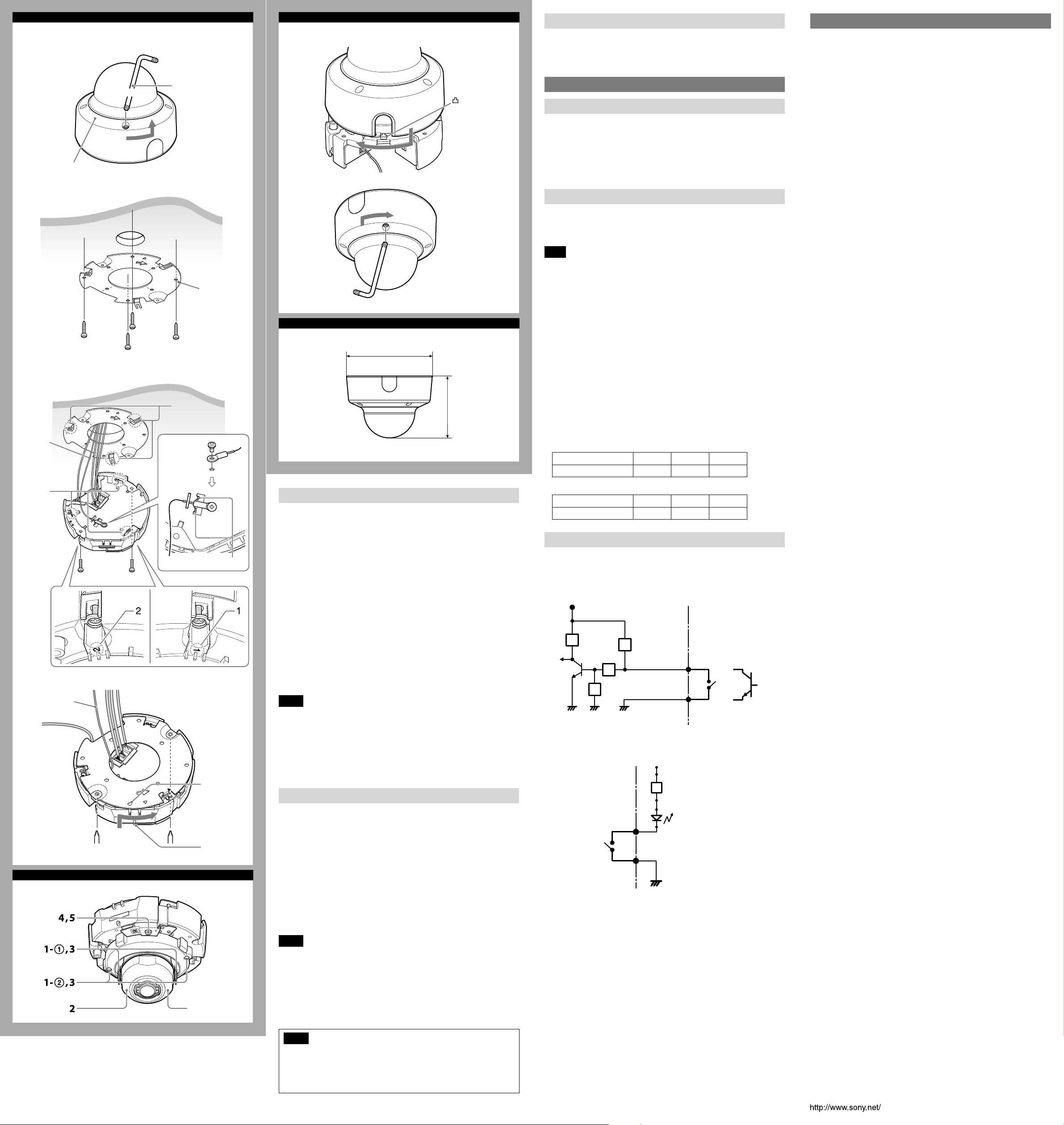
Installing the Camera
1
Remove the dome casing.
Loosen the screw with the wrench (supplied).
Turn the dome casing anticlockwise, and remove it from the camera unit.
When the screw catches on the screw hole, pull up the screw.
2 Install the supplied bracket on the ceiling or wall.
Refer to “Mounting screws” for screws to be used.
3 Fix the supplied wire rope to the camera unit and the ceiling or wall.
Fix the wire rope with the supplied M3 screw to the hole for the wire rope
on the bottom of the camera unit.
Pass the wire rope between the wire rope guides.
Fix the wire rope to the ceiling or wall.
4 Attach the camera unit to the bracket.
Align the projection on the top and bottom of the camera’s card slot with
the bracket mounting screw hole on the bracket.
Turn the camera unit lightly in the direction of the arrow (clockwise
rotation), then lock the temporary tightening hook of the camera (3
positions).
Turn the camera in the rotational direction until it completely stops and
tighten the camera unit mounting screws in the order of 1, then 2.
Notes
Be sure to tighten the camera unit mounting screws in the order of 1, then 2. ˎ
Otherwise, the camera unit may not be secure and could fall.
If you cannot use screws on a ceiling or wall, or if you want to make the ˎ
camera less conspicuous, use the YT-ICB600 in-ceiling bracket (optional) with
which you can mount the camera on the ceiling.
When you install the camera with the in-ceiling bracket, tighten the fixing
screw on the side brackets to the position. Refer to the in-ceiling bracket
Installation Instructions for details.
Adjusting the Camera Direction and Coverage
You can adjust all pan, tilt and rotation positions. There is no screw for rotation
position.
Turn the lens case to rotate the camera.
You can invert the image by using the setting menu.
1 Loosen the camera head fixing screw.
Loosen the tilt screws (2 positions).
Loosen the pan screws (2 positions).
2 Adjust the camera to turn the lens in the desired direction.
3 Tighten the camera head fixing screw to fix the camera. (4 positions)
4 Slide the ZOOM/FOCUS switch to W/T to adjust the zoom.
5 Hold down the ZOOM/FOCUS switch for a moment to automatically
adjust the focus.
6 Repeat steps 1 to 5 until the coverage and the focus are determined.
Attaching the Dome Casing
1
Align the notch on the dome casing with the convex part on the rear of
the camera unit, then turn the dome casing in the direction of the arrow.
2 Tighten screws.
3 Remove the protecting film on the dome cover.
Connection
Connecting to the Network
Connect the LAN connector of the camera to a PoE* supported device (such as a
hub) using the network cable (straight cable).
The electrical power is supplied through the network cable. For details, refer to
the instruction manuals of the PoE supported devices.
(* PoE: The acronym for Power over Ethernet. IEEE 802.3af standard compliant
devices.)
For SNC-VM641, it is possible to connect the LAN port of the camera to a router
or hub in the network using a commercially-available network cable.
Connecting the Power Source
The camera can be powered in the following ways.
12 V DC or 24 V AC (Either voltage supported by SNC-VM641 only.) ˎ
Power supply equipment pursuant to IEEE802.3af (PoE* system) ˎ
*PoE means Power over Ethernet.
Note
Do not turn off the camera immediately after turning it on. Wait for at least five ˎ
minutes before turning off the camera.
Do not connect the power input cable if power is supplied by a PoE system. ˎ
Connecting to the power supply equipment pursuant to
IEEE802.3af
The power supply equipment pursuant to IEEE802.3af supplies the power
through the network cable. For details, refer to the Instruction Manual of the
equipment.
Connecting to 12 V DC or 24 V AC source
Connect the power input cable of the camera to a 12 V DC or 24 V AC source.
Use a 12 V DC or 24 V AC source isolated from 100 to 240 V AC. Each usable ˎ
voltage ranges are as follows.
12 V DC: 10.8 V to 13.2 V
24 V AC: 19.2 V to 28.8 V
- In the USA, The product shall be powered by a UL Listed Class 2 Power
Supply Only.
- In Canada, The product shall be powered by a CSA certified Class 2 Power
Supply Only
Use UL cable (VW-1 style 10368) for these connections. ˎ
Recommended cable
DC 12 V:
CABLE (AWG) #24 #22 #20
Max. length (m (feet)) 9 (29.5) 15 (49.2) 23 (75.5)
AC 24 V:
CABLE (AWG) #24 #22 #20
Max. length (m (feet)) 37 (121.4) 63 (206.7) 92 (301.8)
Connecting the I/O Cable (SNC-VM641)
Connect the wires of the I/O cable as follows:
Wiring diagram for sensor input
Mechanical switch/open collector output device
Camera inside
3.3 V
10 K
Ω
2.2 K
Ω
10 K
Ω
10 K
GNDGND
Ω
GND
Sensor input +
Sensor input −
(GND)
Wiring diagram for alarm output
Camera inside
5 V
R
Alarm Output +
Magnet relay –
24 V AC
24 V DC,
1 A or less
Alarm Output –
Circuit example
GND
Outside
Outside
Mechanical switch
or
Open collector
output device
Specifications
Compression
Video compression format JPEG/H.264
Audio compression format G.711/G.726/AAC
Maximum frame rate 60 fps
Camera
Signal system NTSC color system/PAL color system
Image device 1/2.8type CMOS (Exmor R)
Synchronization Internal synchronization
Horizontal resolution 700 TV lines (monitor display ratio 4:3)
Video S/N More than 50 dB (Auto gain control maximum
Minimum illumination View-DR Off/VE*Off/Auto gain maximum rate
* VE stands for Visibility Enhancer.
Lens
Focal length 3.0 mm to 9.0 mm
Maximum relative aperture F1.2 to F2.1
View angle 1920 × 1080 (aspect ratio 16:9)
Movable angle Pan: −192° to +192°
Minimum object distance 300 mm
Interface
LAN port (PoE) 10BASE-T/100BASE-TX, auto negotiation (RJ-45)
I/O port (SNC-VM641 only) Sensor input: × 2, make contact, break contact
SD memory card slot
Video output VIDEO OUT: BNC, 1.0 Vp-p, 75 ohms,
Microphone input* Minijack (monaural)
Line input* Minijack (monaural)
* The microphone input and the line input are switchable with operating menu.
Line output Minijack (monaural), Maximum output level:
Others
Power supply SNC-VM641:
Power consumption 6.0 W max.
Operating temperature Start temperature: 0°C to 50°C (32°F to 122°F)
Storage temperature –20°C to +60°C (–4°F to +140°F)
Operating humidity 20% to 80% (no condensation)
Storage humidity 20% to 80% (no condensation)
Dimensions (diameter/height)
Mass Approx. 835 g (1 lb 13 oz) (excluding cable or
Supplied accessories Bracket (1), Template (1), Wire rope (1), Camera
Optional accessory
In-ceiling bracket YT-ICB600*
* Using the fixture position on the bracket.
Dome Cover Smoked YT-LD601S
Design and specifications are subject to change without notice.
(switchable)
Effective number of pixels: Approx. 2,130,000
rate 0 dB)
MAX/30 IRE (IP) /30 fps
F1.2/Color: 0.006 lx, Black & White: 0.005 lx
Vertical: 56.9° to 20.1°
Horizontal: 105.3° to 35.6°
Tilt: −7° to +75°
Rotation: −99° to +99°
Alarm output: × 2, 24 V AC/DC, 1 A
(mechanical relay outputs electrically isolated
from the camera)
unbalanced, sync negative
Plug-in-power supported (rated voltage: 2.5 V DC)
Recommended load impedance: 2.2 kΩ
1 Vrms
12 V DC ±10%
24 V AC ±20% 50 Hz/60 Hz
IEEE802.3af compliant (PoE system)
SNC-EM641:
IEEE802.3af compliant (PoE system)
Working temperature: −10°C to +50°C (14°F to
122°F)
148 mm × 108 mm (5
bracket)
unit mounting screw M3 (1), Wrench (1), Audio
cable (1), BNC cable (1), Safety regulation, I/O
cable (1) (SNC-VM641 only), Power input cable
(1) (SNC-VM641 only)
7
/8 inches × 4 3/8 inches)
Lens case
Notes
When you adjust the camera head angle without loosening camera head ˎ
fixing screw, an internal part may be damaged.
Be sure to turn off the setting of superimposing when adjusting the focus. ˎ
If you cannot achieve satisfactory focus with holding down the ZOOM/FOCUS ˎ
switch due to the shooting environment, slide the ZOOM/FOCUS switch level
to N/F to focus manually.
Poor focus may also be caused by the dome case assembly. Readjust the focus ˎ
using the system menu.
For details, refer to the User's Guide of the equipment.
Notes
When the dome casing is attached it may be visible in the monitor ˎ
depending on zoom and rotation. Also, distortion might be observed in
images shot outside the specified optical area.
Do not turn the tilt screw more than 360 degrees and pan screw more than ˎ
2-3 turns, as they may become loose and fall out.
 Loading...