

Page 1
8
4-538-945-11(1)
Network Camera
Installation Manual
Before operating the unit, please read this manual thoroughly and
retain it for future reference.
SNC-EB602R/EB632R
© 2014 Sony Corporation
A
Printed in China
E
Ceiling
F
Wire rope
(supplied)
Camera unit
mounting screw
(not supplied) (4)
Ground wire
Ground the camera when you install it.
LAN cable (RJ-45)
Connect this cable to a hub or computer on the 10BASE-T or 100BASE-TX
network using a commercially available network cable (UTP, category 5).
Note
Take care not to trap the cables between the camera and the ceiling or the wall. If
the cable is trapped, it may cause a fire or electric shock due to breaking.
Sun shield
The sun shield can be adjusted horizontally up to 26 mm (1 1/8 inches), as
required.
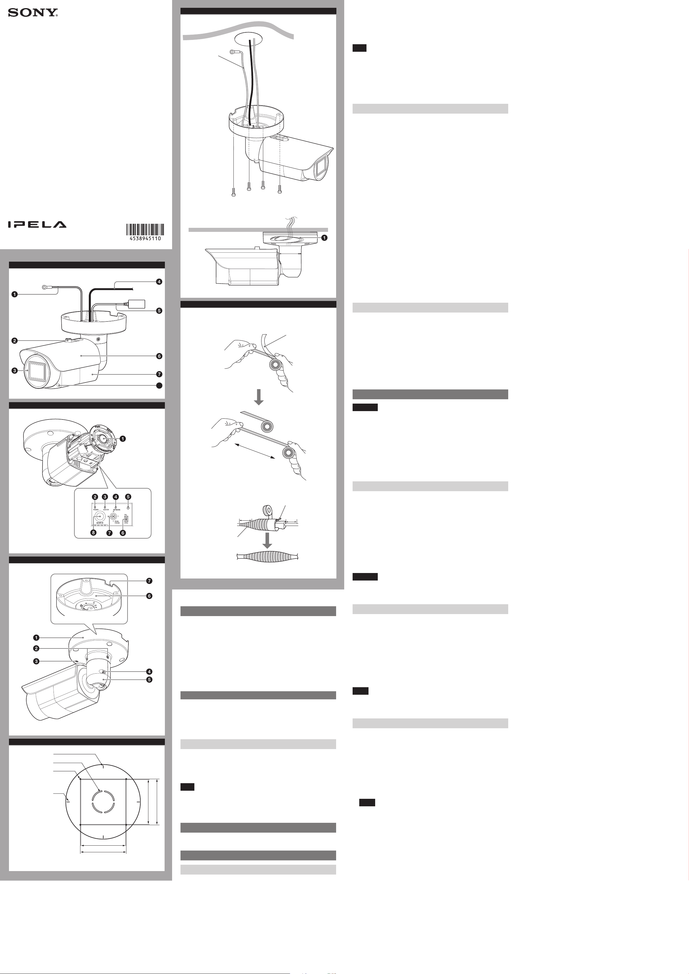
Camera
Front cover screw (four positions)
Inside
Lens
POWER indicator (Green)
When the power is supplied to the camera, the camera starts checking the
system. If the system is normal, this indicator lights up.
HEATER indicator (Green)
The indicator lights up in green when the built-in heater is working normally.
NETWORK indicator (Green/Orange)
The indicator lights up or flashes when the camera is connected to the network.
The indicator is off when the camera is not connected to the network.
Reset switch
To reset the camera to the factory default settings, hold down this switch with a
point and supply the power to the camera.
VIDEO (NTSC/PAL) switch (Initial setting: NTSC)
Switches the video output.
After setting the switch, reboot the camera unit.
ZOOM/FOCUS switch
Use this switch to adjust lens’ zoom and focus. Slide the switch lever to select the
desired function.
[W] WIDE: Zoom out
[T] TELE: Zoom in
[N] NEAR: Focus on a nearby subject
[F] FAR: Focus on a distant subject
Hold down the center of the ZOOM/FOCUS switch for a moment to focus
automatically.
MONITOR output jack
Connect this jack to a video input connector of a video monitor. You can adjust
the camera or lens while looking at the image on the video monitor. After
adjusting the camera or lens, disconnect the cable.
Back
2
Liner
Base stand
Base screw (two positions)
TOP mark
Arm screw
Arm
Rating label
Shows the name of this camera and its electric rating.
Water drain
When installing the unit on a wall, make sure this water drain is not sealed.
Installation
B
Twice
WARNING
If you attach the camera in the height such as the wall or the ceiling, etc.,
entrust the installation to an experienced contractor or installer.
If you install the camera at a height, ensure that the installation location and
its material are strong enough to withstand a weight of 15 kg (33 lb 11 oz) or
more, and then install the camera securely. If the ceiling is not strong enough,
the camera may fall and cause serious injury.
Do not pull on any cables forcefully, as a connection may become loose.
To prevent the camera from falling, make sure to attach the supplied wire rope.
If you attach the camera to the ceiling, check periodically, at least once a year,
to ensure that the connection has not loosened. If conditions warrant, make
this periodic check more frequently.
C
D
Vertical marker
Hole for connecting
cables ø40 (1
Hole for installing
the stand
Horizontal maker
5
/8)
83.7 (3
85.7 (3
Deciding the Installation Location of the Camera
3
Tab
1
10 (
/2) 10 (1/2)
Overlap at least
half of its width
Unit: mm (inches)
About the Manuals
Installation Manual (this document)
This Installation Manual describes the names and functions of parts and controls
of the Network Camera, gives connection examples and explains how to set up
the camera. Be sure to read the Installation Manual before operating.
SNC easy IP setup Guide (stored in the CD-ROM)
User’s Guide/Application Guide (Web)
The User’s Guide describes how to set up the camera and how to control the
camera via a Web browser.
After installing and connecting the camera correctly, operate referring to this
User’s Guide.
Using the Software
The supplied CD-ROM includes the setup program for assigning an IP address.
The information for how to set up an IP address is also included in the disc in PDF
format.
User’s Guide and Application Guide can be downloaded from the disc, or the
following URL:
http://www.sony.net/ipela/snc
Using the CD-ROM manual
The manual can be read on a computer with Adobe Reader installed.
You can download Adobe Reader free from the Adobe website.
1 Open the index.html file in the CD-ROM.
2 Select and click on the manual that you want to read.
)
)
8
10
/
/
3
3
85.7 (3
83.7 (3
3
/10)
3
/8)
Note
If you have lost or damaged the CD-ROM, you can purchase a new one from your
Sony dealer or Sony service counter.
Adobe and Acrobat Reader are trademarks of Adobe Systems Incorporated in the
United States and/or other countries.
Assigning the IP address
Assign the IP address using the setup program in the supplied CD-ROM.
For details on how to set up the IP address, see SNC easy IP Setup Guide.
After deciding the direction in which the camera will shoot, make the required
hole (ø40 mm (1 23/40 inches)) for the connecting cables using the supplied
template. Then decide the four mounting hole positions to install the bracket.
Mounting screws
The camera stand is provided with four ø4.5 mm (3/16 inches) mounting holes.
Install the camera stand on a ceiling or wall with screws through four mounting
holes: The required mounting screws differ depending on the installation
location and its material. (Mounting screws are not supplied.)
Steel wall or ceiling: Use M4 bolts and nuts.
Wooden wall or ceiling: Use M4 tapping screws. The panel thickness must be
15 mm (5/8 inches) or more.
Concrete wall: Use anchors, bolts and plugs suitable for concrete walls.
Junction box: Use screws to match the holes on the junction box.
WARNING
The required mounting screws differ depending on the installation location and
its material. If you do not secure the camera with the appropriate mounting
screws, the camera may fall off.
Installing the Camera
1
Pass the LAN cable and the ground wire through the hole for connecting
cables made at the installing surface.
2 Fix the wire rope to the wall or ceiling.
3 Install the camera on the wall or ceiling.
The remaining cable can be incorporated in the space between the base
stand and the mounting surface. (-)
Insert the four screws in the screw holes on the camera stand, and then
tighten the screws to attach the camera.
When installing the camera on the wall, be sure the TOP mark on the camera
stand is at the top.
Refer to “Mounting screws” in section D for screw to be used.
Notes
If you install the camera unit on a ceiling, take adequate waterproofing
measures to prevent water seepage into the stand.
When installing the unit on a wall, make sure the water drain is not sealed.
Notes on waterproofing of cable connection area
Despite the fact that this unit is rated IP66, the cables and/or the connectors
join to the outside are not waterproof. To prevent water ingress from the cables
and/or the connectors, waterproof them with the supplied waterproof tape as
follows. Otherwise, there may be a risk of water entering through the cables and/
or the connectors and shorting the unit or the connectors.
1 Connect the LAN cable and the ground wire.
2 To obtain optimal waterproofing, tear off the liner before wrapping,
then stretch the tape to twice its original length.
If it is not fully stretched, the waterproofing function of the tape can not be
achieved.
3 Overlap the tape at least half of its width when wrapping.
Notes
Do not press the network cable tab down when wrapping it.
Make sure at least 10 mm (
1
/2 inches) of the wire part is wrapped.
4 After wrapping, squeeze the tape with your fingers at the overlapping
parts so that layers are airtight and fully adhered.
(continued overleaf)
Location and Function of Part
Unit: mm (inches)
Front
Wire rope
When installing the camera on the ceiling or the wall, make sure to attach the
supplied wire rope.
Sun shield nut
Front cover
Page 2
G
4
1
Correct
Front coverCamera unit
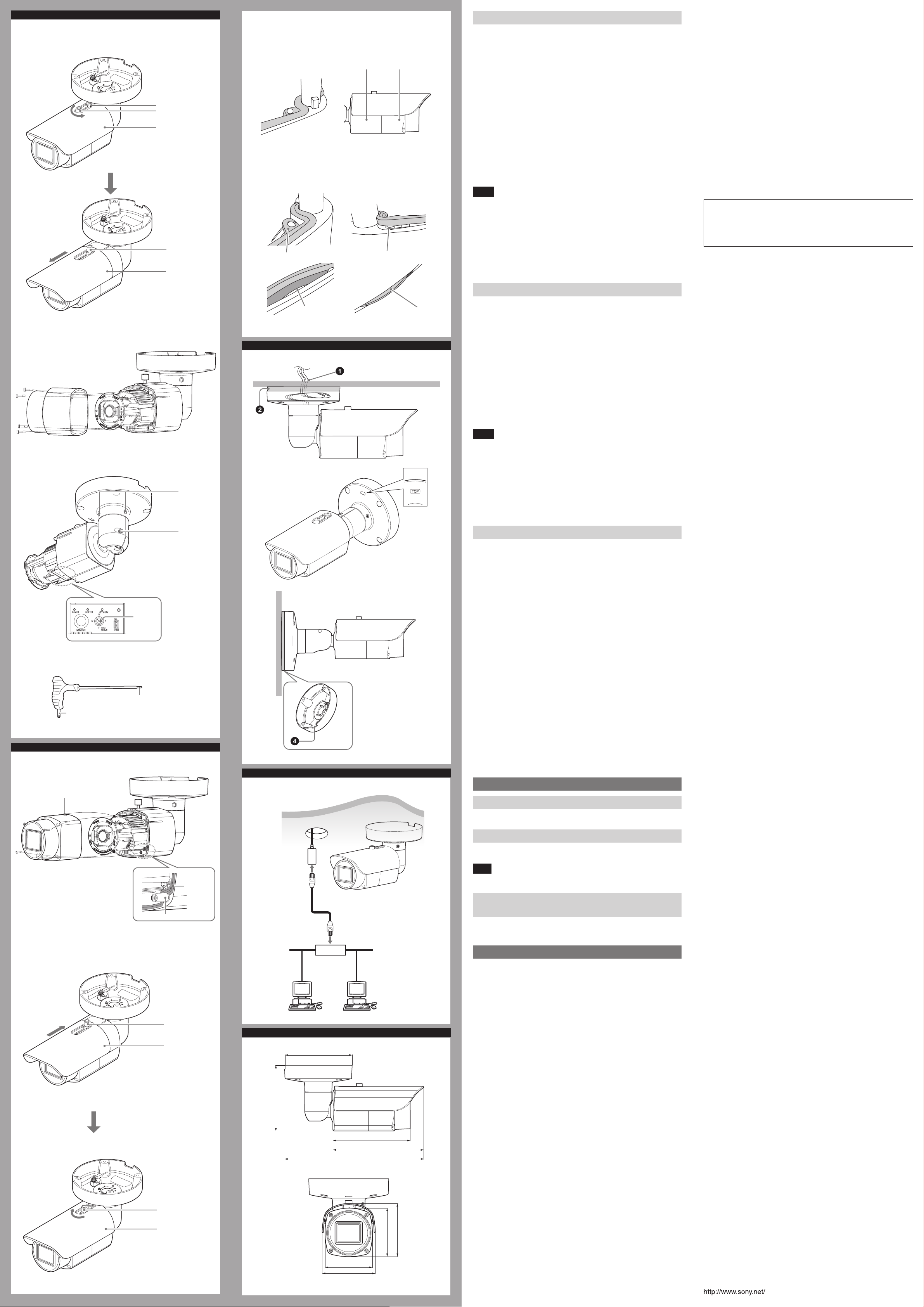
Adjusting the Camera Direction and Coverage
If the MONITOR output jack is used, adjust the camera direction and coverage as
described from steps 1 to 8.
When viewing the image with the LAN cable, adjust the camera direction and
coverage as described from steps 3 to 5.
1 Fully loosen the sun shield nut until the sun shield can be slid to the front
end (when the nut is located at the back hole of sun shield slide slot),
and take off the sun shield.
2 Loosen the four front cover screws with the supplied wrench, and take
off the front cover.
Back hole
Sun shield nut
Sun shield
3 First loosen the two base screws with the supplied wrench, then loosen
the arm screw.
To fine adjust, only loosen the arm screw.
4 Adjust the camera to turn the lens in the desired direction.
5 First tighten the two base screws with the supplied wrench, then tighten
The waterproof rubber
gasket fits in the groove
properly.
After installing the front cover,
the gap between the front cover
and the camera unit is even.
the arm screw (tightening torque: 2.0 N·m).
6 Adjust the zoom by the ZOOM/FOCUS switch (W/T).
7 Hold down the center of the ZOOM/FOCUS switch for a moment to focus
automatically.
8 Repeat steps 3 to 7 until the coverage and the focus are determined.
Sun shield nut
Sun shield
Wrong
Detached
Uneven gap
Notes
When adjusting the camera direction and coverage, do not touch the front
cover waterproof rubber gasket to prevent it from being contaminated,
detached or damaged. Otherwise, water enters the camera.
If you cannot achieve satisfactory focus by holding down the ZOOM/FOCUS
switch due to the shooting environment, slide the ZOOM/FOCUS switch level
to N/F to focus manually.
Do not turn off this unit as soon as the focus is adjusted. Turn off after five
minutes have passed since the focus was adjusted.
Distortion might be observed in images shot outside the specified optical
area.
Interface
LAN port (PoE) 10BASE-T/100BASE-TX, auto negotiation (RJ-45)
Others
Power supply IEEE802.3af compliant (PoE system)
Power consumption SNC-EB602R: 10.0 W
Operating temperature Start temperature:
Storage temperature -20°C to +60°C (-4°F to +140°F)
Operating humidity 20% to 90%
Storage humidity 20% to 95%
Dimensions (diameter/height)
Mass Approx. 1,450 g (3 lb 3 oz)
Supplied accessories
Design and specifications are subject to change without notice.
SNC-EB632R: 11.4 W
-20°C to +50°C (-4°F to +122°F)
Working temperature:
-30°C to +50°C (-22°F to +122°F)
93 mm × 93 mm × 160.9 mm (3
3 3/4 inches × 6 3/8 inches), not including the
projecting parts
CD-ROM (supplied programs) (1), Template (1),
Wrench (1), Installation Manual (this document)
(1 set), Safety Regulations (1 set), Waterproof
tape (1)
3
/4 inches ×
Recommendation of Periodic Inspections
In case using this device over an extended period of time, please have it
inspected periodically for safe use.
It may appear flawless, but the components may have deteriorated over time,
which may cause a malfunction or accident.
For details, please consult the store of purchase or an authorized Sony dealer.
2
3,4,5,6,7
Base screw
Attaching the front cover and the sun shield
1
Check if the waterproof rubber gasket is contaminated, detached or
Uneven gap
Foreign matter stuck
I
damaged.
2 Align the four front cover screw holes with the bosses on the camera.
Make sure the TOP mark on the front cover is at the top, then tighten
the four screws with the supplied wrench to secure the front cover.
(tightening torque: 0.4 N·m)
3 Align the back hole of sun shield slide slot with the sun shield nut to
install the sun shield, adjust the sun shield to the desired position, then
tighten the sun shield nut manually.
Adjust the sun shield position as follows:
Loosen the sun shield nut manually.
Do not loosen the sun shield nut too much, to prevent it from sliding to
the back hole of sun shield slide slot.
Adjust the sun shield to the desired position horizontally.
Tighten the sun shield nut manually to secure the sun shield.
Notes
Make sure the waterproof rubber gasket is clean and fits in the groove
properly. After installing the front cover, make sure the gap between the front
cover and the camera unit is even. Make sure there is no uneven gap or foreign
matter stuck on the gasket. Otherwise, water enters the camera. (-4)
Poor focus may also be caused by the front cover assembly. Readjust the focus
using the system menu.
For details, refer to the User’s Guide of the equipment.
When adjusting the factory-set position of the sun shield forward, the sun
shield or dark vignetting may be observed in the upper sides of the images.
Also, the image quality will be reduced when the IR LED is operating.
Wrench (supplied)
H
1,2
TOP mark
For fixing the base
screws/arm screw
ZOOM/
FOUCS
switch
For fixing the
front cover screw
Boss (four positions)
Arm screw
Rubber
gasket
J
Ceiling
LAN cable
Network cable
(straight, not
supplied)
10BASE-T/
100BASE-TX
Important precautions
Despite the fact that this unit is rated IP66, this section includes important
precautions to prevent any malfunction caused by condensation and/or water
ingress. Read the precautions below thoroughly before installing the unit.
Make sure that the cables and/or connectors of the unit that join to the
ones of the installation surface are waterproofed, before you install the unit.
Otherwise, there may be a risk of water entering the unit through these cables.
Make sure to waterproof the cables and/or connectors with the supplied
waterproof tape as stipulated in this manual. Otherwise, there may be a risk of
water entering and shorting the unit. For details, see “Notes on waterproofing
of cable connection areas” in the front page.
Install the camera stand on an even ceiling, wall, etc.
When installing the unit in an inverted position (on a ceiling, for
example)
Install the unit in a waterproof box or on a waterproof ceiling to prevent water
entering the unit along the cables. Alternatively, seal the hole which is made
for the connecting cables at the installing surface. (-)
Cover all around the joint part of the installing surface and the camera stand
with sealant to prevent water ingress. (-)
When installing the unit in a vertical position (on a wall, for
example)
Make sure the TOP mark on the camera stand is at the top. (
Cover all around the joint part of the installing surface and the camera stand
(except the water drain -) with sealant to prevent water ingress.
-)
Notes on assembly
Make sure the cable and the wire rope do not get caught between the base
stand and the mounting surface.
Before attaching the front cover to the camera unit, make sure the waterproof
rubber gasket is clean and fits in the groove properly.
Connection
Connecting to the Network
Connect the LAN port of the camera to a router or hub in the network using a
commercially available network cable (not supplied).
Connecting the Power Source
Power supply equipment pursuant to IEEE802.3af (PoE* system)
*PoE means Power over Ethernet.
Note
Do not turn off the camera immediately after turning it on. Wait for at least five
minutes before turning off the camera.
Connecting to the power supply equipment pursuant
to IEEE802.3af
The power supply equipment pursuant to IEEE802.3af supplies the power
through a commercially available network cable. For details, refer to the
Instruction Manual of the equipment.
Specifications
3
Sun shield nut
K
Sun shield
/8)
3
136.3 (5
Sun shield nut
Sun shield
PoE supported
device (such as a
hub)
ø140 (5 5/8)
160.9 (6
288.3 (11
83 (3 3/8)
3
/4)
93 (3
Unit: mm (inches)
3
188.6 (7
3
/8)
/8)
1
/2)
/8)
3
85 (3
/4)
3
93 (3
Compression
Video compression format JPEG/H.264
Audio compression format G.711/G.726/AAC
Maximum frame rate 30 fps
Camera
IR LED 10 pcs (SNC-EB602R)/20 pcs (SNC-EB632R)
IR working distance SNC-EB602R: 25 m (50 IRE)
SNC-EB632R: 30 m (50 IRE)
Signal system NTSC color system/PAL color system
(switchable)
Image device SNC-EB602R
1/3type CMOS (Exmor)
Effective picture elements:
Approx. 1,370,000
SNC-EB632R
1/2.9type CMOS (Exmor)
Effective picture elements:
Approx. 2,140,000
Synchronization Internal synchronization
Horizontal resolution SNC-EB602R: 600 TV lines (analog video)
SNC-EB632R: 700 TV lines (monitor display ratio
4:3)
Minimum illumination F1.2/View-DR Off/VE* Off/Auto gain control
maximum rate MAX/50 IRE (IP)/30 fps
SNC-EB602R
Color: 0.05 lx
Black & White: 0 lx (IR ON)
SNC-EB632R
Color: 0.10 lx
Black & White: 0 lx (IR ON)
* VE stands for Visibility Enhancer.
Lens
Focal length 3.0 mm to 9.0 mm
Maximum relative aperture F1.2 ~ F2.1
View angle SNC-EB602R: 1280 × 1024 (aspect ratio 5:4)
Vertical: 73.1° to 25.5°
Horizontal: 92.9° to 31.8°
SNC-EB632R: 1920 × 1080 (aspect ratio 16:9)
Vertical: 56.9° to 20.1°
Horizontal: 105.3° to 35.6°
Minimum object distance 300 mm
 Loading...