

Page 1
3-858-505-12 (1)
Video Cassette
Player
Operating Instructions
SLV-KA175PK
SLV-KA185PK
SLV-KF285PK
©1996 by Sony Corporation
SLV-KA175PK/KA185PK/KF285PK 3-858-505-12 (1)
Page 2
WARNING
To prevent fire or shock hazard, do
not expose the unit to rain or
moisture.
This symbol is intended to alert
the user to the presence of
uninsulated “dangerous
voltage” within the product’s
enclosure that may be of
sufficient magnitude to constitute a risk of
electric shock to persons.
This symbol is intended to alert
the user to the presence of
important operating and
maintenance (servicing)
instructions in the literature
accompanying the appliance.
• Keep the unit and cassettes away from
equipment with strong magnets, such as
microwave ovens or large loudspeakers.
• Do not place heavy objects on the unit.
• If the unit is brought directly from a cold to
a warm location, moisture may condense
inside the unit and cause damage to the
video head and tape. When you first install
the unit, or when you move it from a cold to
a warm location, wait for about one hour
before operating the unit.
Caution
Television programs, films, video tapes and
other materials may be copyrighted.
Unauthorized recording of such material may
be contrary to the provisions of the copyright
laws. Also, use of this unit with cable
television transmission may require
authorization from the cable television
transmission and/or program owner.
Precautions
Safety
• Operate the unit on 110 – 240 V AC, 50/60
Hz.
• If anything falls into the cabinet, unplug the
unit and have it checked by qualified
personnel before operating it any further.
• Unplug the unit from the wall outlet if you
do not intend to use it for an extended
period of time. To disconnect the cord, pull
it out by the plug, never by the cord.
Installing
• Allow adequate air circulation to prevent
internal heat buildup.
• Do not place the unit on surfaces (rugs,
blankets, etc.) or near materials (curtains,
draperies) that may block the ventilation
slots.
• Do not install the unit near heat sources
such as radiators or air ducts, or in a place
subject to direct sunlight, excessive dust,
mechanical vibration or shock.
• Do not install the unit in an inclined
position. It is designed to be operated in a
horizontal position only.
Introduction
2
SLV-KA175PK/KA185PK/KF285PK 3-858-505-12 (1)
Page 3

Table of contents
Getting Started
4 Step 1: Unpacking
5 Step 2: Setting up the remote commander
6 Step 3: Hookups
Basic Operations
11 Playing a tape
Additional Operations
14 Playing/searching at various speeds
16 Karaoke sing-along
19 Adjusting the picture
20 Editing with another VCR
Additional Information
22 General setup information
23 Troubleshooting
25 Specifications
26 Index to parts and controls
Back cover
Index
Getting Started
Introduction
SLV-KA175PK/KA185PK/KF285PK 3-858-505-12 (1)
3
Page 4
Getting Started
Step 1
Unpacking
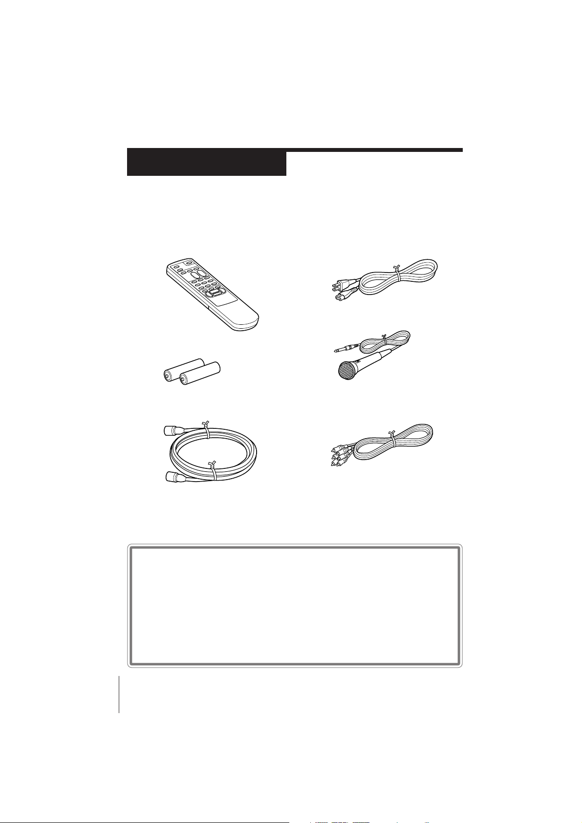
Check that you have received the following items with the unit:
• Remote commander
• Size AA (R6) batteries
• 75-ohm coaxial cable with F-type
connectors
• AC power cord
• Microphone
• Audio/video cable (3-phono to 3phono) (SLV-KF285PK only)
Checking your model name
The instructions in this manual are for the 3 models: SLV-KA175PK,
KA185PK, and KF285PK. Check your model number by looking at
the rear panel of your unit. The SLV-KA185PK is the model used for
illustration purposes. Any difference in operation is clearly indicated
in the text, for example, “SLV-KF285PK only.”
Getting Started4
SLV-KA175PK/KA185PK/KF285PK 3-858-505-12 (1)
Page 5
Step 2
Setting up the remote commander
Inserting the batteries
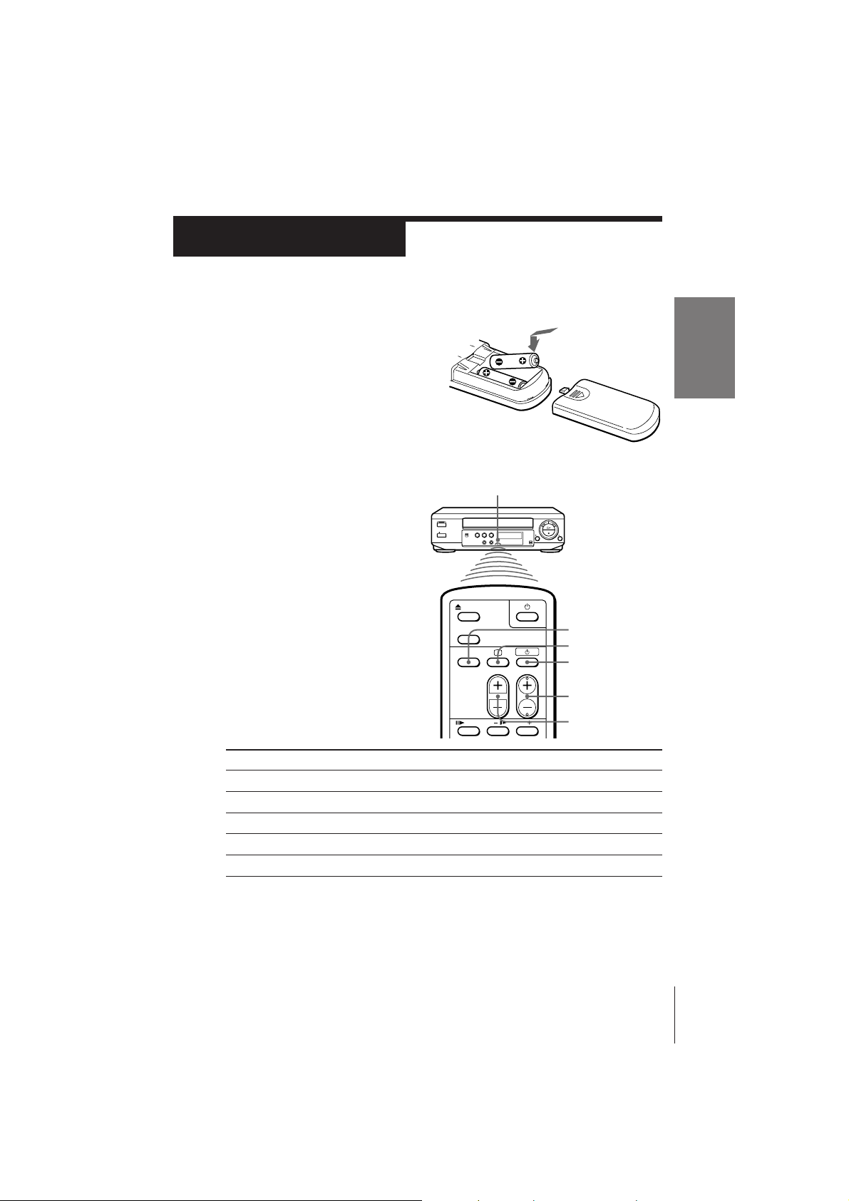
Insert two R6 (size AA) batteries by
matching the + and – on the batteries
to the diagram inside the battery
compartment.
Using the remote commander
You can use this remote
commander to operate the unit
and a Sony TV. To operate this
unit, point at the remote sensor
on the unit. To operate the TV,
point at the remote sensor on
the TV.
Remote sensor
TV/VIDEO
;
u
Getting Started
PROG(CH) +/–
VOL +/–
To
Turn the TV to standby or active mode
Turn on the TV power
Increase (+) or decrease (–) the TV volume
Change the TV channel
Select an input source of the TV either from antenna in or from line in
Notes
• With normal use, the batteries should last about three to six months.
• If you do not use the remote commander for an extended period of time, remove
the batteries to avoid possible damage from battery leakage.
• Do not use a new battery with an old one.
• Do not mix different types of batteries.
Press
u
;
VOL +/–
PROG(CH) +/–
TV/VIDEO
Getting Started
SLV-KA175PK/KA185PK/KF285PK 3-858-505-12 (1)
5
Page 6

Step 3
Hookups
Selecting the hookup
There are basically two ways to hookup this unit depending on whether
your TV has audio/video inputs or not.
If your TV has audio/video inputs
See “Audio/video (A/V) hookup” on pages 7 and 8.
If your TV doesn’t have audio/video inputs
See “Antenna hookup” on pages 9 and 10.
Before you get started
• Turn off the power to all equipment.
• Do not connect the AC power cords until all of the connections are
completed.
• Be sure you make connections firmly. Loose connections may cause
picture distortion.
• If your TV doesn’t match any of the examples provided, see your nearest
Sony dealer or qualified technician.
Getting Started6
SLV-KA175PK/KA185PK/KF285PK 3-858-505-12 (1)
Page 7
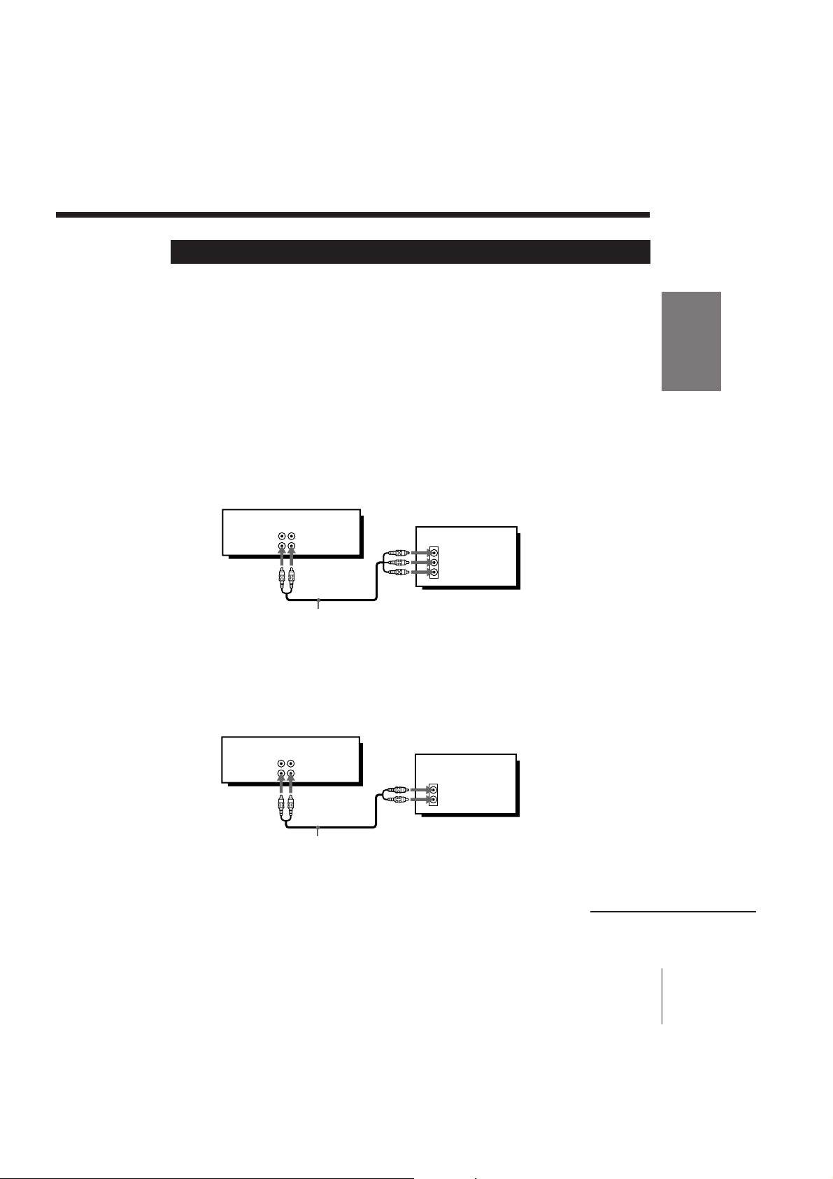
Audio/video (A/V) hookup
If your TV has audio/video (A/V) input jacks, you will get a better picture
and sound if you hook up your unit using these connections.
For SLV-KF285PK, you should also connect the audio outputs of your unit or
TV to your stereo system for a true “home theater” experience.
You’re finished setting up the unit after you’ve made the connections.
If your TV doesn’t have A/V inputs, see page 9 for antenna hookup.
(For SLV-KA175PK/KA185PK)
A Use this hookup if your TV has stereo jacks
(e.g. SLV-KA185PK)
This unit
AUDIO VIDEO
LINE IN
LINE OUT
TV
IN
VIDEO
AUDIO
Audio/video cable (not supplied)
B Use this hookup if your TV doesn’t have stereo jacks
Getting Started
(e.g. SLV-KA185PK)
This unit
AUDIO VIDEO
LINE IN
LINE OUT
Audio/video cable (not supplied)
TV
IN
VIDEO
AUDIO
continued
Getting Started
SLV-KA175PK/KA185PK/KF285PK 3-858-505-12 (1)
7
Page 8
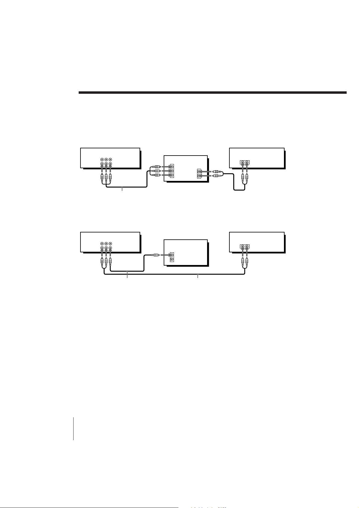
Step 3: Hookups (continued)
(For SLV-KF285PK)
A Use this hookup if your TV has stereo jacks
This unit
AUDIO VIDEO
LINE IN
LINE OUT
TV
IN
VIDEO
AUDIO
AUDIO OUT
Audio/video cable (supplied)
B Use this hookup if your TV doesn’t have stereo jacks
This unit
AUDIO VIDEO
LINE IN
LINE OUT
Video cable (not supplied) Audio cable (not supplied)
Note (SLV-KF285PK only)
• To play a tape in stereo, you must use the A/V connection.
TV
IN
VIDEO
AUDIO
Stereo receiver
AUX IN
Stereo receiver
AUX IN
Getting Started8
SLV-KA175PK/KA185PK/KF285PK 3-858-505-12 (1)
Page 9
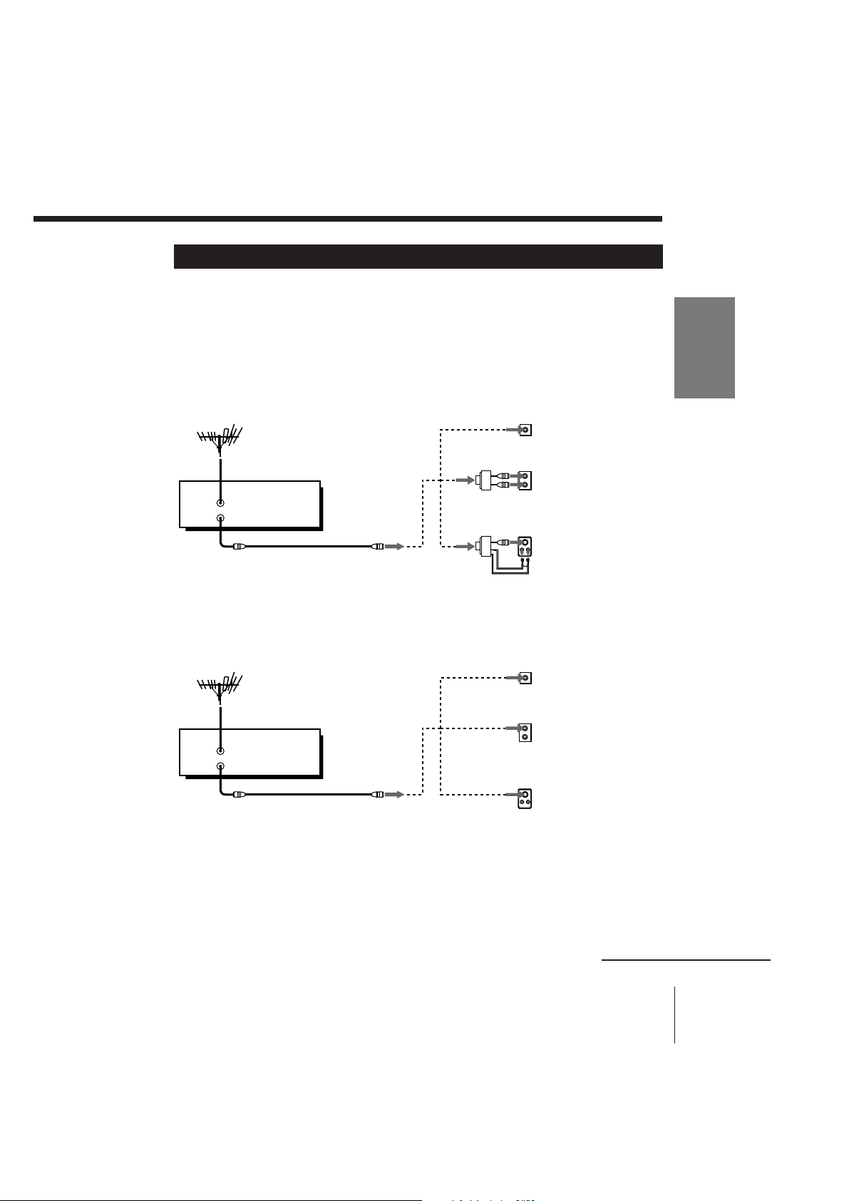
Antenna hookup
Make the following connections if your TV doesn’t have A/V inputs.
A Use this hookup if you’re using:
• VHF/UHF antenna (you get channels 2–13 and channels 14 and higher)
• UHF-only antenna (you get channels 14 and higher)
• Separate VHF and UHF antennas
Rear of TV
VHF/UHF
A
Match the type of
connector on your
TV: A, B, or C.
B
This unit
VHF/UHF
IN
OUT
or
VHF
UHF
or
VHF
C
UHF
B Use this hookup if you’re using a VHF-only antenna (you get
channels 2–13 only)
Rear of TV
Match the type of
connector on your
A
TV: A, B, or C.
B For connector types
B and C, no UHF
connection is
required.
C
This unit
VHF/UHF
IN
OUT
VHF/UHF
or
or
VHF
UHF
VHF
UHF
Getting Started
If you cannot connect your antenna cable to the unit directly
If your antenna cable is a flat cable (300-ohm twin lead cable), attach an external
antenna connector (not supplied) so you can connect the cable to the VHF/UHF IN
connector. If you have separate cables for VHF and UHF antennas, you should use a
U/V band mixer (not supplied). For details, see page 22.
continued
Getting Started
SLV-KA175PK/KA185PK/KF285PK 3-858-505-12 (1)
9
Page 10
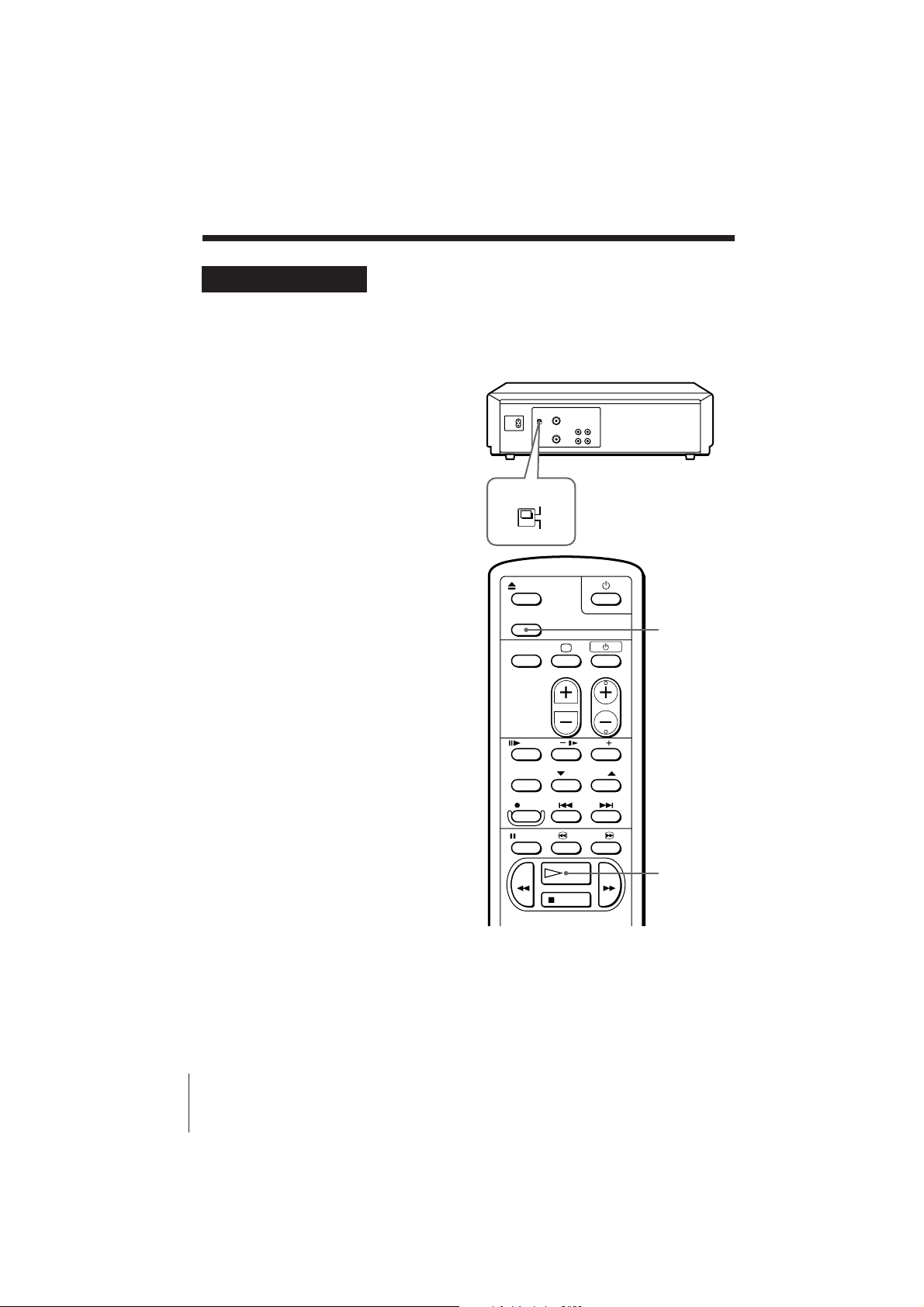
Antenna hookup: Video cassette player setup
When connecting the unit to the TV using only the antenna cable, you must
set the RF UNIT switch on the rear of the unit so that the TV can receive the
correct signal from the unit.
1 Set the RF UNIT switch to
CH 3 or CH 4, whichever
channel is not used in your
area. If both are used, set the
switch to either channel.
2 Insert a recorded tape into
the tape compartment.
(SLV-KA175PK)
The unit turns on and starts
playing automatically.
(SLV-KA185PK/KF285PK)
The unit turns on and starts
playing automatically if you
insert a tape with its safety
tab removed.
RF UNIT
CH3
CH4
3 Press TV/VTR to turn on the
TV/VTR indicator in the
display window.
4 Press · PLAY (if playback
didn’t start in step 2).
5 Turn on your TV and set it to
the channel you selected in
step 1 (channel 3 or 4).
The video playback picture
will be clearly displayed on
the TV screen.
Whenever you use the unit,
set the TV to the channel
selected in step 1.
TV/VTR
· PLAY
Getting Started10
SLV-KA175PK/KA185PK/KF285PK 3-858-505-12 (1)
Page 11
Basic Operations
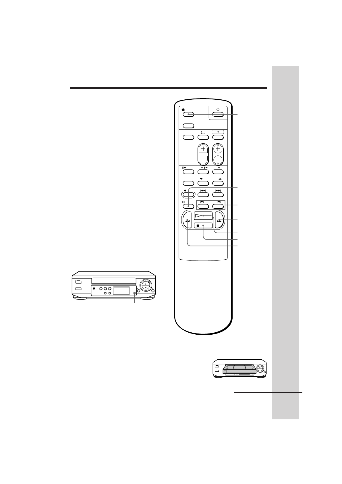
Playing a tape
6 EJECT
P PAUSE
3/#
SEARCH
) FF
· PLAY
p STOP
0 REW
Basic Operations
PICTURE
1 Turn on your TV and set it to the video channel.
2 Insert a tape.
(SLV-KA175PK)
The unit turns on, and starts playing
automatically.
SLV-KA175PK/KA185PK/KF285PK 3-858-505-12 (1)
continued
Basic Operations
11
Page 12
Playing a tape (continued)
(SLV-KA185PK/KF285PK)
The unit turns on, and starts playing
automatically if you insert a tape with its
safety tab removed.
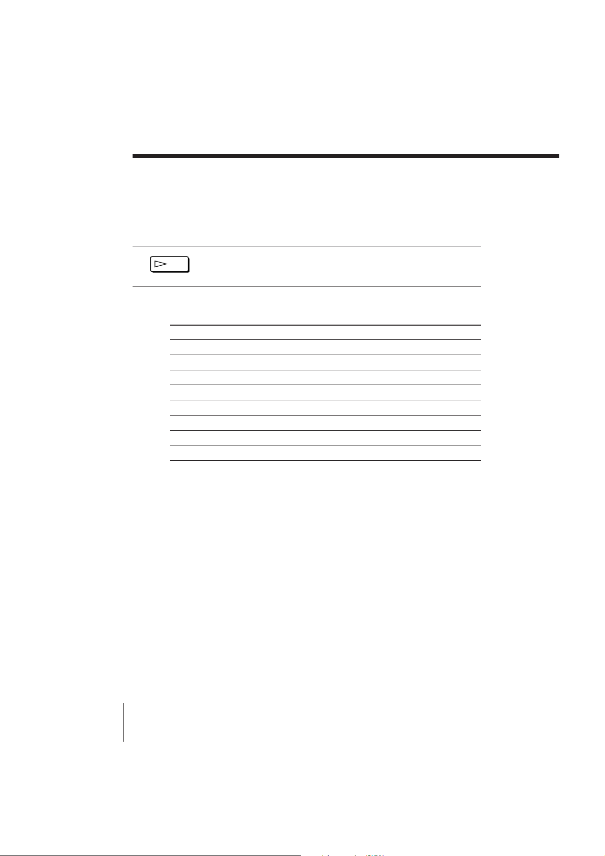
3 Press · PLAY (if playback didn’t start in step 2).
PLAY
When the tape reaches the end, it will rewind automatically.
Additional tasks
To
Stop play
Pause play
Resume play after pause
Search forward
Search backward
Fast-forward the tape
Rewind the tape
Eject the tape
Press
p STOP
P PAUSE
P PAUSE or · PLAY
) FF or # SEARCH during playback
0 REW or 3 SEARCH during playback
) FF during stop
0 REW during stop
6 EJECT
Watching a rental tape
Set PICTURE on the unit to RENTAL PICTURE. Noise will be reduced on
the playback picture. After watching the rental tape, set the switch back to
NORMAL.
Basic Operations
12
SLV-KA175PK/KA185PK/KF285PK 3-858-505-12 (1)
Page 13
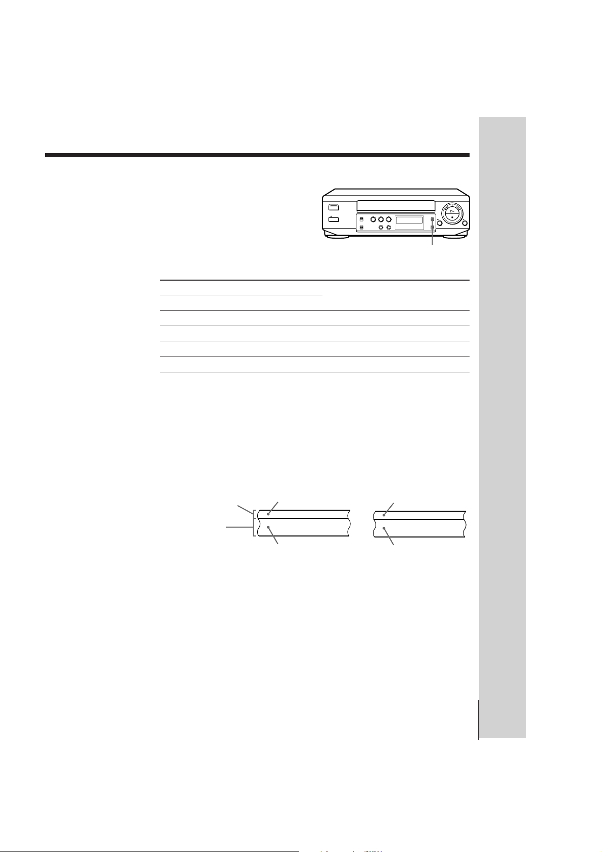
Selecting the sound during playback (SLV-KF285PK only)
Press AUDIO MONITOR to
select the desired sound. Each
press of the button changes the
display on the unit. When you
play a tape recorded in stereo
or with a bilingual sound track,
the HiFi indicator on the unit
AUDIO MONITOR
lights up.
To listen to a
Stereo tape’s
Stereo sound
Left channel
Right channel
Standard sound*
* The mixed sound of left and right channels (monaural)
Bilingual tape’s
Main and sub sounds
Main sound
Sub sound
Standard sound*
Press AUDIO MONITOR until the
display window indicator shows
“L/R”
“L”
“R”
No indication
How sound is recorded on a video tape
The unit records sound onto two separate tracks. Hi-fi audio is recorded
onto the main track along with the picture. Monaural sound is recorded
onto the normal audio track along the edge of the tape.
Stereo Bilingual
Mixed left/right
channels
Normal audio track
(monaural)
Hi-fi audio track
(main track)
Stereo sound
(left/right
channels)
Mixed left/right
channels
Main (left channel)
Sub (right channel)
Basic Operations
Notes
• When the pause mode lasts for more than approximately five minutes, the unit
will automatically enter the playback mode.
(SLV-KF285PK only)
• To listen to playback sounds in stereo, you must use the LINE OUT connections.
• When you play a tape recorded in monaural, the sound is heard in monaural
regardless of the AUDIO MONITOR setting.
Basic Operations
SLV-KA175PK/KA185PK/KF285PK 3-858-505-12 (1)
13
Page 14
Additional Operations
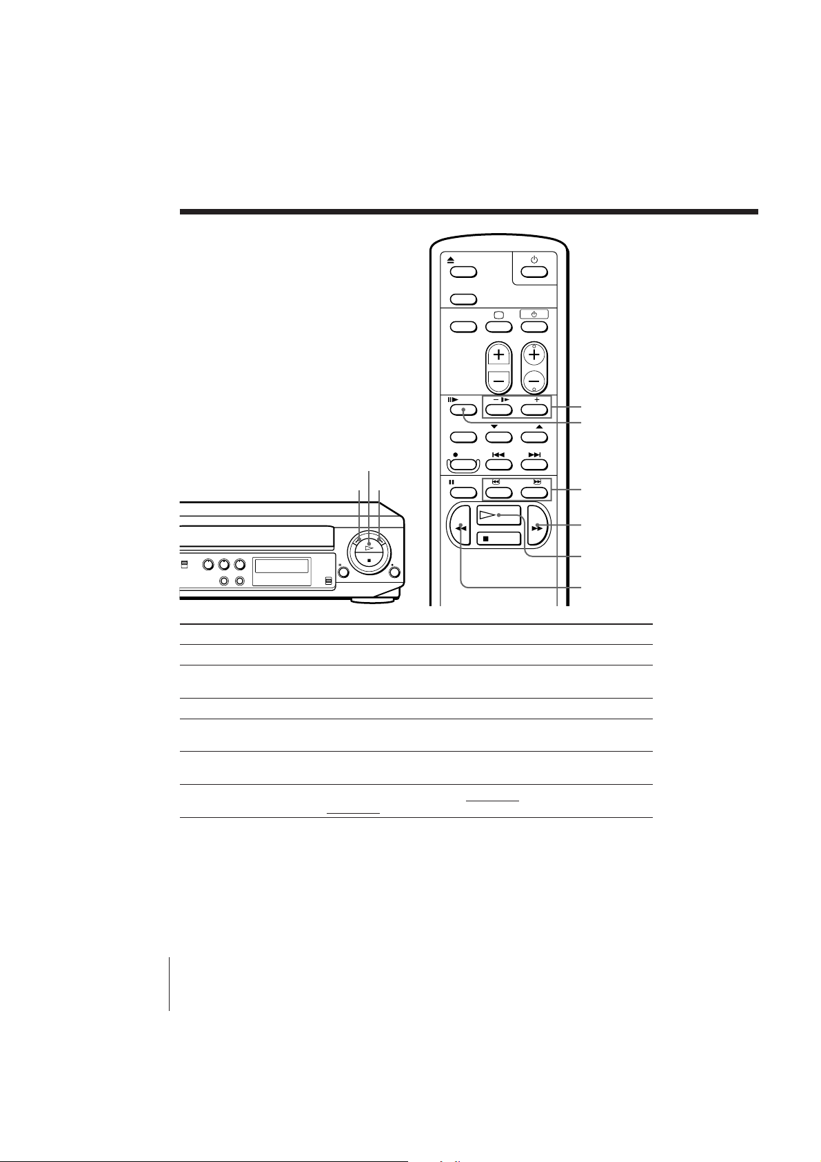
Playing/searching
at various speeds
· PLAY
0 REW
) FF
& SLOW +/–
7 FRAME
3/#
SEARCH
) FF
· PLAY
0 REW
Playback options
Fast-forward/rewind
View the picture during fastforward or rewind
Play at high speed
Play in slow motion
Play frame by frame
Rewind and start play
To resume normal playback
Press · PLAY.
Additional Operations
14
Operation
During stop, press ) FF or 0 REW.
During fast-forward, hold ) FF down. During rewind, hold
0 REW down.
During playback or pause, press # SEARCH or 3 SEARCH.
During playback or pause, press & SLOW+/–. Press the +/–
buttons to change the speed.
During pause, press 7 FRAME to advance the picture one frame.
Hold the button down to play one frame each second.
During stop, hold 0 REW on the unit down and press · PLAY
on the unit.
SLV-KA175PK/KA185PK/KF285PK 3-858-505-12 (1)
Page 15

Tip
• If the picture shakes while in the still mode, adjust the picture using $/4
TRACKING NORMAL/SLOW STILL ADJUST on the unit.
Notes
• Streaks or snow cannot be eliminated completely in the various playback
operations.
• The sound is muted during these operations.
Additional Operations
SLV-KA175PK/KA185PK/KF285PK 3-858-505-12 (1)
15
Page 16
Karaoke singalong
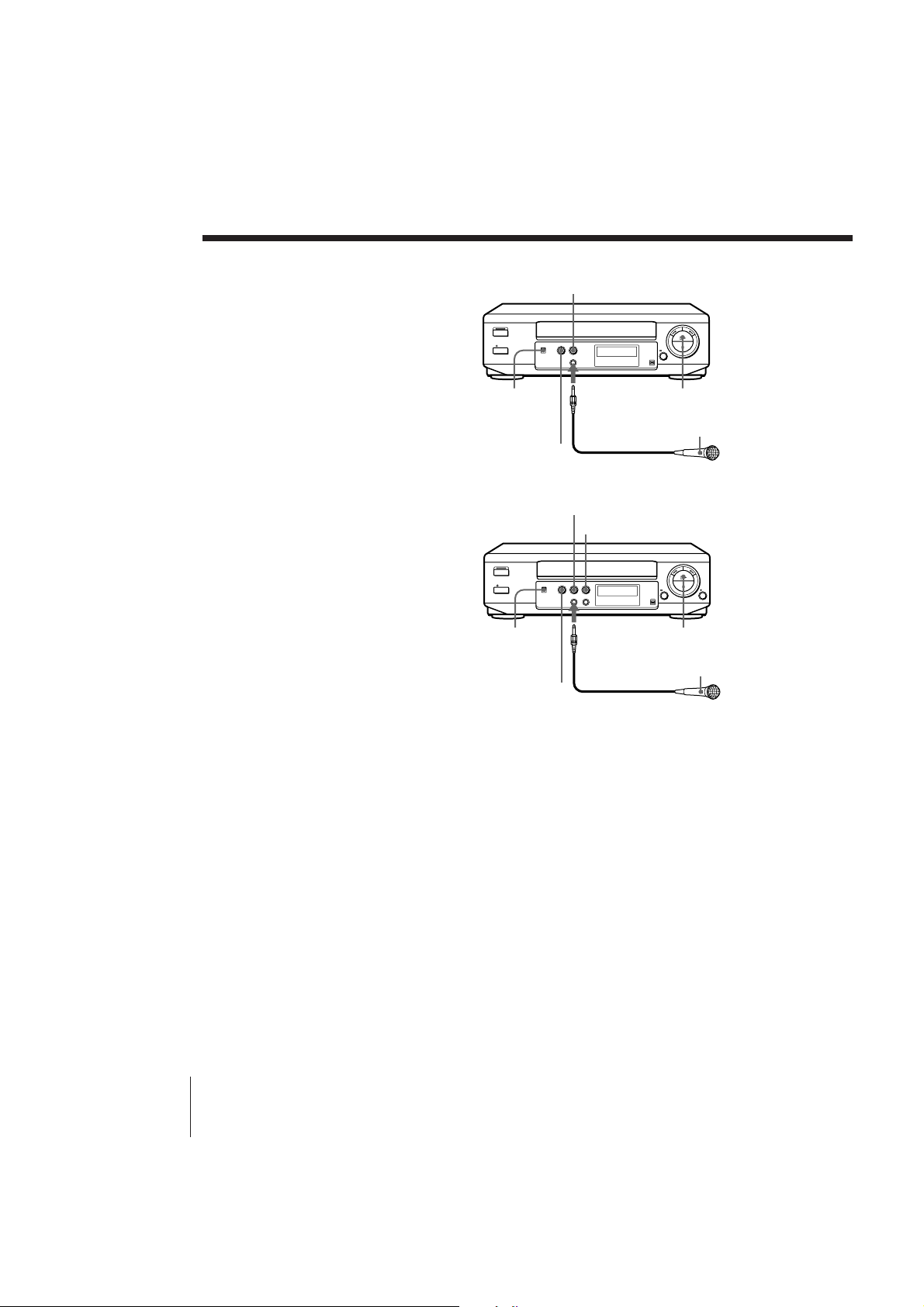
You can sing along with a karaoke
videotape played back on this unit.
(SLV-KA185PK/KF285PK only)
You can also sing along with a TV
broadcast or music played back on
equipment connected to the LINE IN
jacks on the rear panel of the unit. If you
use an extra microphone (not supplied),
you can sing duets.
Before you start...
• Turn on your TV and set it to the
video channel.
(For SLV-KA175PK)
• Connect the supplied microphone to
the MIC IN jack.
(For SLV-KA185PK/KF285PK)
• Connect the supplied microphone to
the MIC IN 1 jack.
To sing duets, connect the optional
microphone to the MIC IN 2 jack.
(e.g. SLV-KA175PK)
MIC VOL
KARAOKE
ON/OFF
ECHO
(e.g. SLV-KA185PK)
MIC VOL 1
KARAOKE
ON/OFF
ECHO
MIC IN
Microphone (supplied)
MIC VOL 2
MIC IN 1/2
Microphone (supplied)
· PLAY
ON/OFF
· PLAY
ON/OFF
Additional Operations
16
Singing along with karaoke video tapes
1 Set KARAOKE ON/OFF to ON.
2 Insert a karaoke video tape.
(SLV-KA175PK)
The unit turns on and starts playing automatically.
(SLV-KA185PK/KF285PK)
The unit turns on and starts playing automatically if you insert a tape
with its safety tab removed.
3 Press · PLAY (if playback didn’t start in step 2).
If you want to playback a specific song, see “Searching with the AMS
function” on the next page.
4 Set the ON/OFF switch on the microphone to ON.
Now you can enjoy playing karaoke.
SLV-KA175PK/KA185PK/KF285PK 3-858-505-12 (1)
Page 17
To adjust the microphone volume
(For SLV-KA175PK)
Turn the MIC VOL control for the microphone connected to MIC IN.
Setting the MIC VOL control to the centre position provides the best
microphone volume.
(For SLV-KA185PK/KF285PK)
Turn the MIC VOL 1 control for the microphone connected to MIC IN 1.
Turn the MIC VOL 2 control for the microphone connected to MIC IN 2.
Setting the MIC VOL 1 and/or 2 control(s) to the centre position provides
the best microphone volume.
To control the echo effect
Turn the ECHO control. This controls both microphones’ echo effect in the
same way.
To get the best effect, adjust the microphone volume to a slightly higher level
than the music volume.
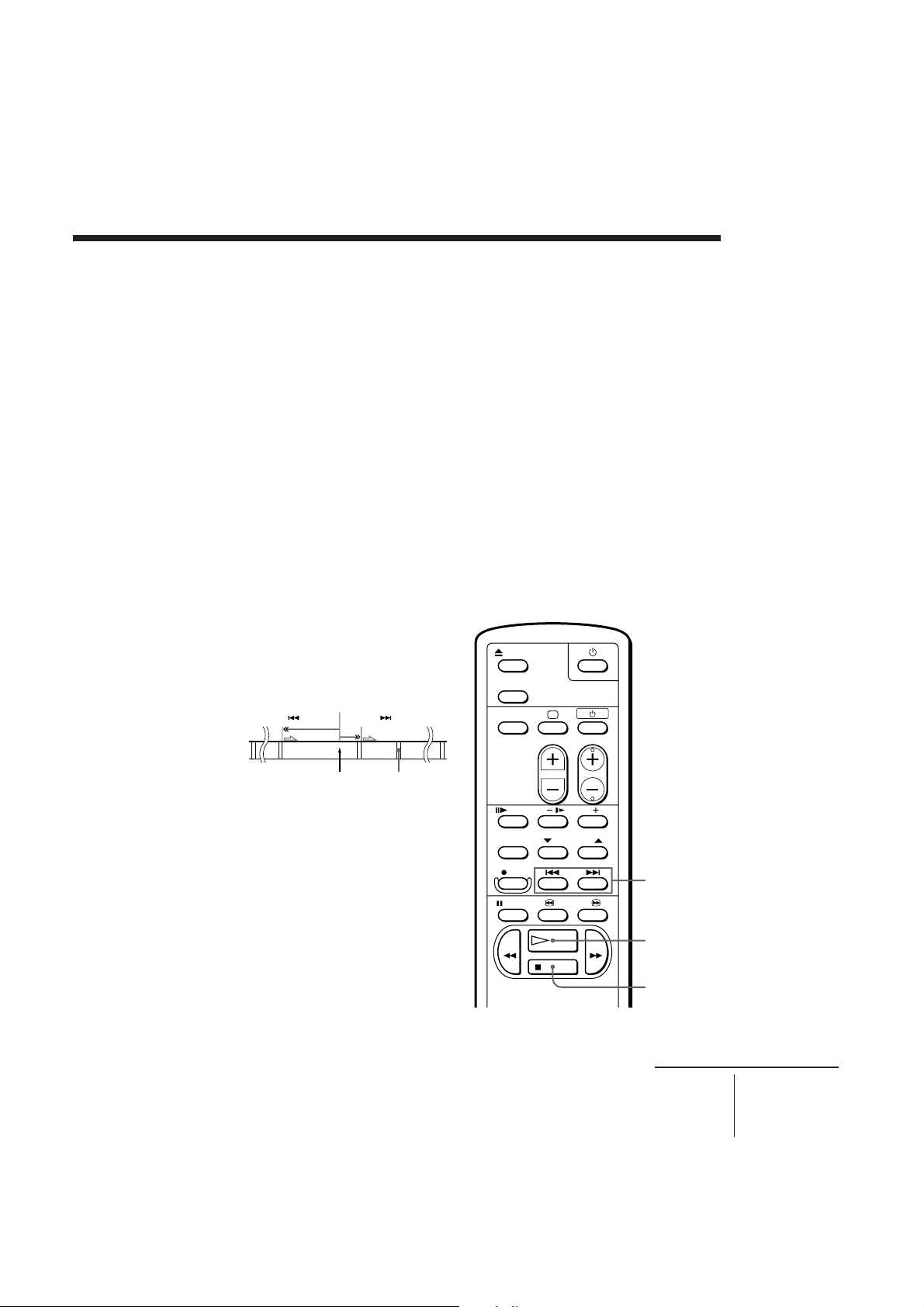
Searching with the AMS function
The AMS (Automatic Music
Sensor) function searches for
the beginning of the next or
previous song by detecting a
blank space between songs.
Present position
Blank space
1 Press p STOP.
2 Press =/+ AMS.
• To locate the beginning of
the next song, press +
AMS.
• To locate the beginning of
the previous song, press
= AMS.
The unit starts searching and
stops automatically when it
locates the beginning of the
next or previous song.
3 Press · PLAY to start playback.
SLV-KA175PK/KA185PK/KF285PK 3-858-505-12 (1)
=/+
AMS
· PLAY
p STOP
continued
Additional Operations
17
Page 18
Karaoke sing-along (continued)
Reducing the playback vocals (Karaoke Pon) (SLVKF285PK only)
You can use ordinary music sources
with vocals for karaoke with this
function. Use hi-fi stereo music
sources.
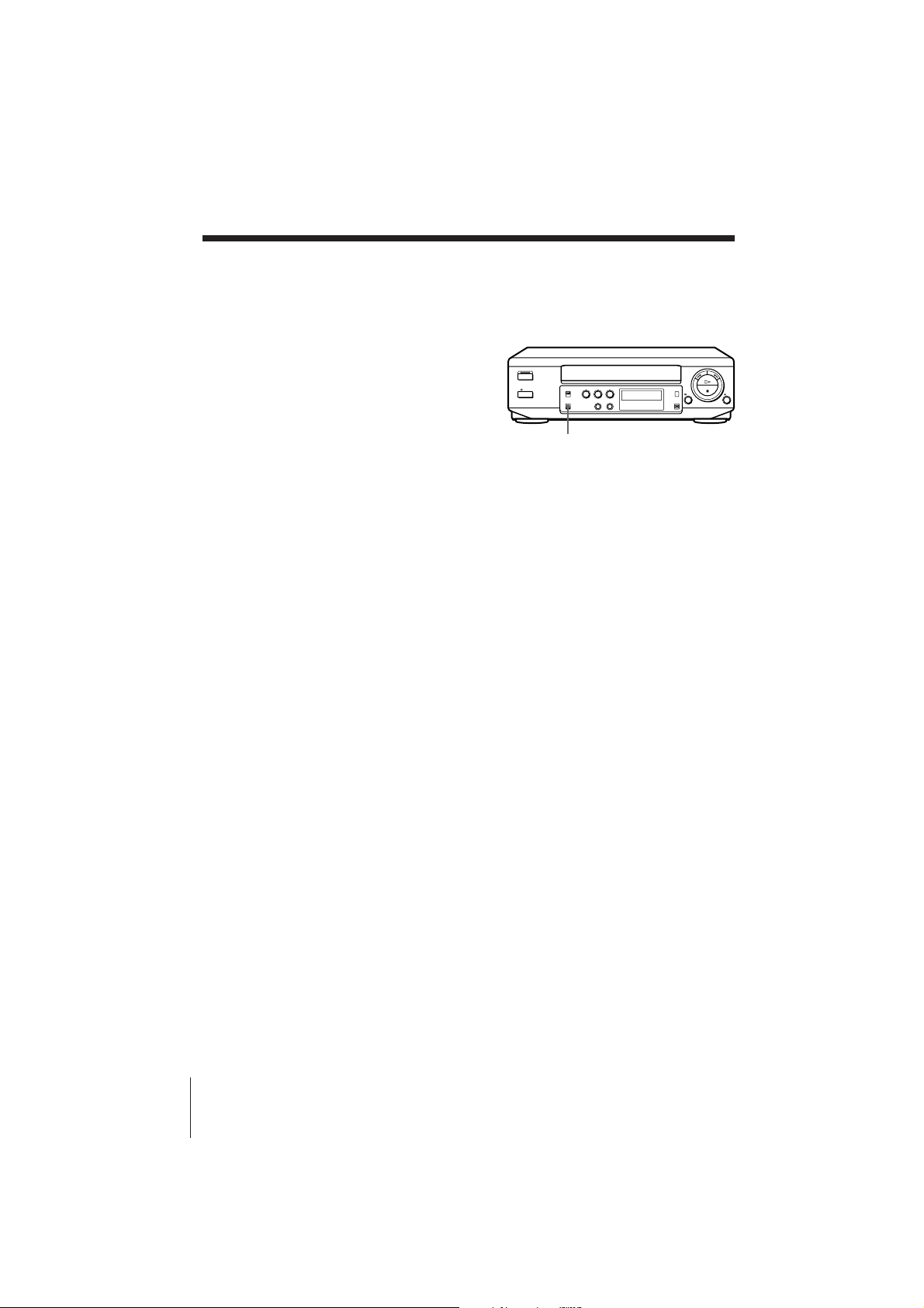
Set KARAOKE PON ON/OFF to
KARAOKE PON.
The singer’s voice will be reduced.
To cancel Karaoke Pon
Set KARAOKE PON ON/OFF to OFF.
Tip (SLV-KA185PK/KF285PK only)
• When you sing along with music played back on equipment connected to the LINE
IN jacks on the unit, play the music source and follow steps 1 and 4 on page 16.
Notes
• If the sound is reproduced through a stereo amplifier, turn down the volume of
amplifier before operation.
• If feedback occurs, turn down the microphone or TV volume, or move the
microphone away from the speakers.
• (SLV-KF285PK only)
Karaoke Pon does not work with the following tapes:
– tapes on which different vocal sounds are recorded on the left and right channels,
such as a duet;
– tapes recorded monaurally; or
– tapes on which sound sources are recorded with strong echo effects and chorus
effects.
• The AMS may not work correctly when:
– the tape quality is poor,
– a song is very short (less than 40 seconds),
– the interval between songs is very short (less than 6 seconds),
– a high level sound is recorded between songs or at the beginning of a song,
– there are low level passages or passages without sound in a song,
– narration is recorded at the beginning of a song,
– fade-in or fade-out recording is made on the tape, or
– AMS starts from the very beginning of the tape or near an interval between
songs.
KARAOKE PON ON/OFF
Additional Operations
18
SLV-KA175PK/KA185PK/KF285PK 3-858-505-12 (1)
Page 19
Adjusting the
picture
Adjusting the tracking
Although the unit
automatically adjusts the
tracking when playing a tape,
distortion may occur if the tape
was recorded in poor
condition. If so, manually
adjust the tracking.
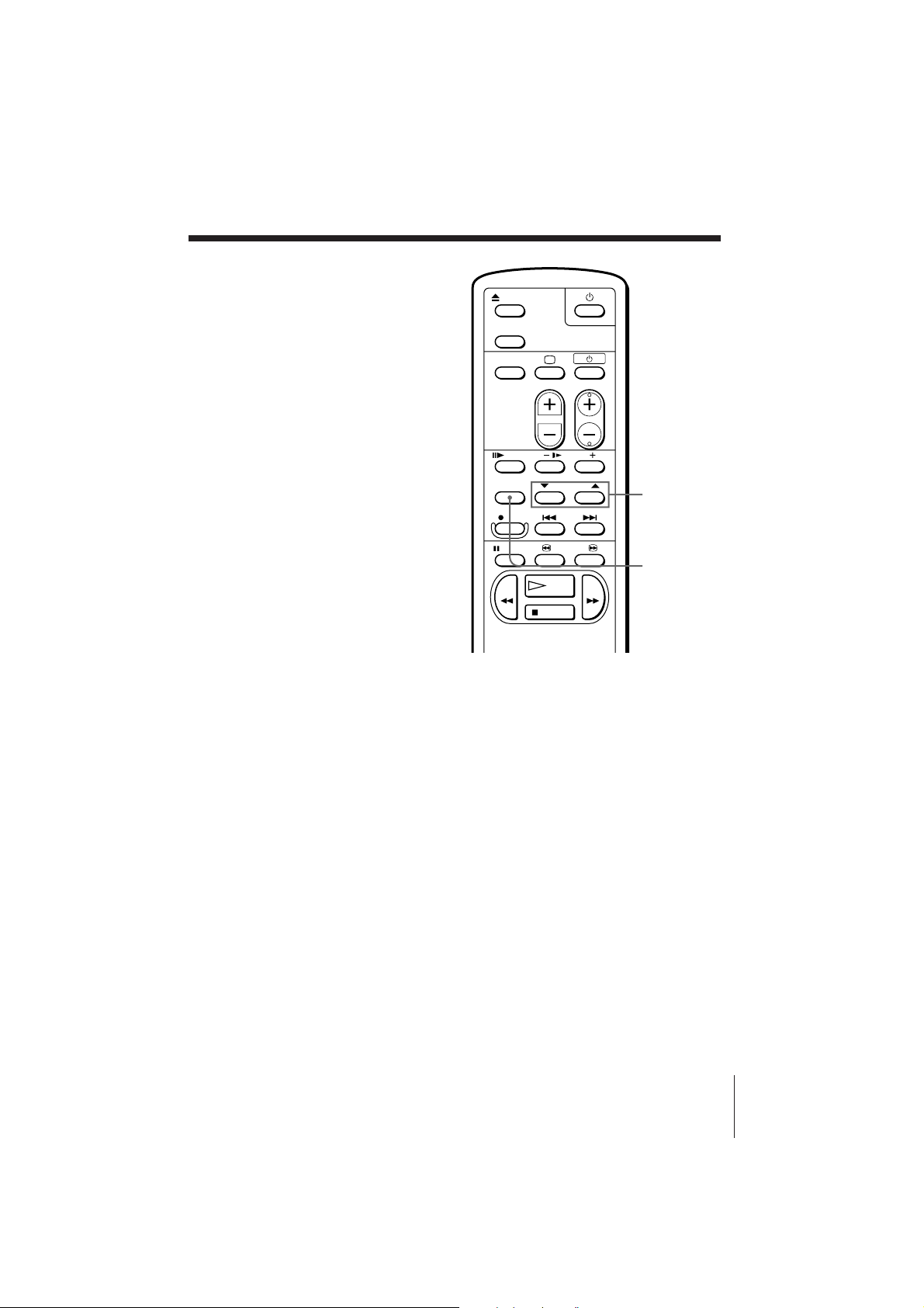
Press $/4 TRACKING
NORMAL/SLOW to obtain the
best possible picture. The
distortion should disappear as
you press one of the two
buttons. If you cannot get a
clear picture with manual
adjustment, press TRACKING
AUTO/MANUAL to return to
automatic adjustment.
About OPC
OPC (Optimum Picture Control) automatically improves playback quality
by adjusting the unit to the condition of the video heads and tape.
The OPC function automatically works on all types of tapes, including rental
tapes. You can play a tape using the OPC function even if the tape was not
recorded with it.
Notes
• The auto tracking function works automatically when you play back a tape just
after inserting it.
• (SLV-KA175PK only)
Sufficient picture quality may not be obtained when playing back tapes recorded in
poor condition.
• (SLV-KA185PK/KF285PK only)
Sufficient picture quality may not be obtained when playing back tapes recorded on
another VCR or tapes in poor condition.
• When a tape recorded with the copyguard system is played back, intermittent
distortion may appear in the upper portion of the picture. However, this is not a
malfunction of the unit.
$/4
TRACKING
NORMAL/
SLOW
TRACKING
AUTO/
MANUAL
Additional Operations
SLV-KA175PK/KA185PK/KF285PK 3-858-505-12 (1)
19
Page 20
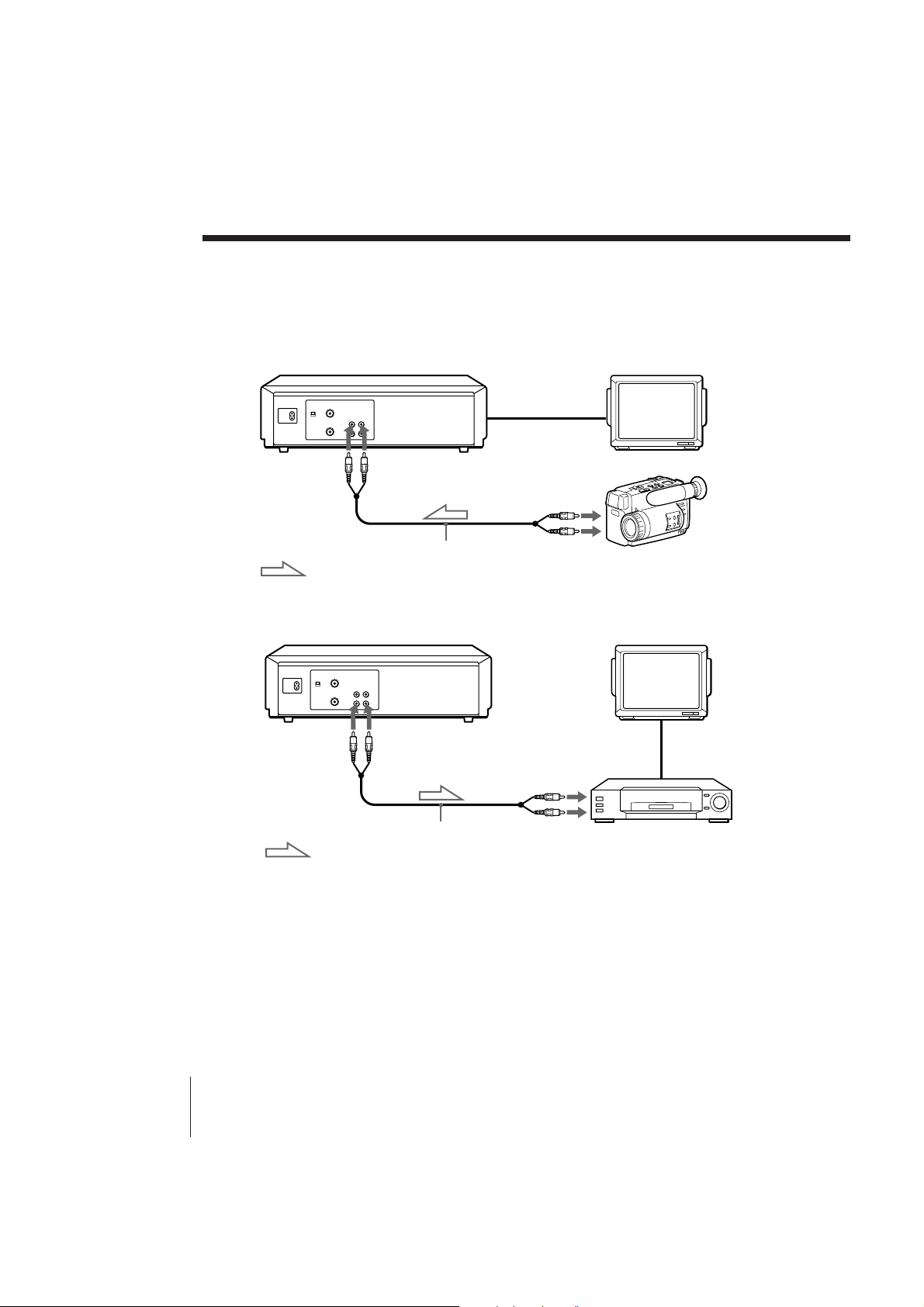
Editing with another VCR
How to connect to record on this unit (SLV-KA185PK
and KF285PK only)
This unit (Recorder)
LINE IN
Other VCR (Player)
LINE OUT
VMC-710M/720M audio/video cable (not supplied)
: Signal flow
How to connect to record to another VCR
This unit (Player)
LINE OUT
LINE IN
TV
TV
Other VCR
(Recorder)
Additional Operations
20
VMC-710M/720M audio/video cable (not supplied)
: Signal flow
Tip
(For SLV-KA175PK/KA185PK)
• If the other VCR is a stereo type, use a connecting cable like the Sony VMC-910MS.
(For SLV-KF285PK)
• Use a connecting cable like the Sony VMC-810. If the other VCR is a monaural type,
use a connecting cable like the Sony VMC-910MS.
Notes
• Make sure you connect the plugs to jacks of the same color.
• (SLV-KA185PK/KF285PK only)
When connecting the units, do not simultaneously connect the LINE IN and LINE
OUT jacks on your unit with the other VCR. A humming noise may occur if you do
this.
SLV-KS295SV/XF245TK 3-858-505-12 (1)
Page 21
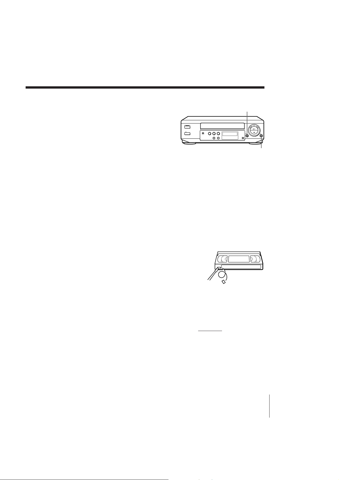
Operation (when recording on this unit) (SLVKA185PK/KF285PK only)
You can make a copy of a tape
using this unit for recording or
playback. The unit cannot record
TV programs directly since it
does not have a TV tuner.
P PAUSE
Before you start editing
• Turn on your TV and set it to
the video channel.
r REC
1 Insert a source tape with its safety tab removed into the other
(playback) VCR. Search for the point to start playback and set it to
playback pause.
2 Insert a tape with its safety tab in place into this (recording) unit.
Search for the point to start recording and press P PAUSE.
3 Press r REC on this unit to set it to recording pause.
4 To start editing, press the P PAUSE buttons on both units at the same
time.
To stop editing
Press the p STOP buttons on both units.
To save a recording
To prevent accidental erasure, break off the safety
tab as illustrated. To record on a tape again, cover
the tab hole with adhesive tape.
Auto head cleaner
The unit incorporates an auto head cleaner which cleans the video heads
when a tape is loaded or unloaded. When the heads are not sufficiently
clean, even after a tape has been loaded/unloaded several times, use the
Sony V-25CL video head cleaning cassette.
Tips
• To edit more precisely, press the P PAUSE buttons on the units to release pause.
• To cut out unwanted scenes while editing, press P PAUSE on this unit when an
unwanted scene begins. When that scene ends, press P PAUSE again to resume
recording.
Note
• You can record tapes only in SP mode.
Safety tab
Additional Operations
SLV-KA175PK/KA185PK/KF285PK 3-858-505-12 (1)
21
Page 22
Additional Information
General setup
information
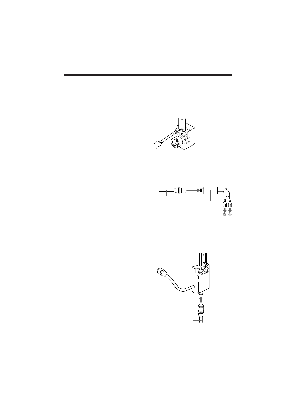
Attaching an external antenna connector
300-ohm to 75-ohm matching transformer
When using a 300-ohm twin lead cable for
VHF/UHF antenna, use an EAC-32 antenna
connector (not supplied) to connect the
antenna to the unit.
1 Loosen the screws on the
antenna connector.
2 Wind the twin leads around the
screws on the antenna
connector.
3 Retighten the screw.
75-ohm to 300-ohm matching transformer
When using a TV with 300-ohm VHF terminal,
use this type antenna connector (not supplied)
to connect the 75-ohm coaxial cable to the TV.
1 Connect the 75-ohm coaxial
cable to the antenna connector.
2 Attach the 300-ohm Y type
terminal to the TV.
75-ohm coaxial
cable
to the 300-ohm VHF terminal
on the TV
300-ohm twin
lead cable
EAC-32 Antenna
connector (not
supplied)
Antenna connector
(not supplied)
Attaching a UHF/VHF band mixer
When using both 75-ohm coaxial cable and
300-ohm twin lead cable for VHF/UHF
antenna, use the EAC-66 UHF/VHF band
separator/mixer (not supplied) to connect the
antenna to the unit.
1 Loosen the screws on the mixer.
2 Wind the twin leads around the
screws on the mixer.
3 Retighten the screws.
4 Connect the 75-ohm coaxial
cable to the mixer.
22
Additional Information
SLV-KA175PK/KA185PK/KF285PK 3-858-505-12 (1)
300-ohm twin
lead cable
EAC-66
UHF/VHF
band
separator/
mixer (not
supplied)
75-ohm coaxial
cable
Page 23
Troubleshooting
If you have any questions or problems not covered below, please consult your
nearest Sony dealer.
Symptom
The POWER switch does not
function.
The power is turned on but the
unit does not operate.
The VCR enters standby mode
or turns off automatically.
Power
The playback picture does not
appear on the TV screen.
The picture is not clear.
Playback
The picture rolls vertically
during picture search.
The picture has no sound.
Remedy
• Connect the AC power cord securely.
• Moisture condensation occurs. Turn the power off,
unplug the AC power cord and leave the unit to dry
for over an hour.
• The auto safety system is triggered to protect your tape
and the unit’s mechanism when there is something
wrong with the tape or when the mechanism is
overloaded. Press u to restart the unit. If the unit
does not work after pressing u again, disconnect the
AC power cord from the wall outlet. Wait for at least
15 seconds. Then reconnect AC power, and press u
again. If the unit still does not work, please consult
your nearest Sony dealer.
• Make sure the TV is set to the video channel. If you
are using a monitor, set it to video input.
• Adjust the tracking with the $/4 TRACKING
NORMAL/SLOW buttons.
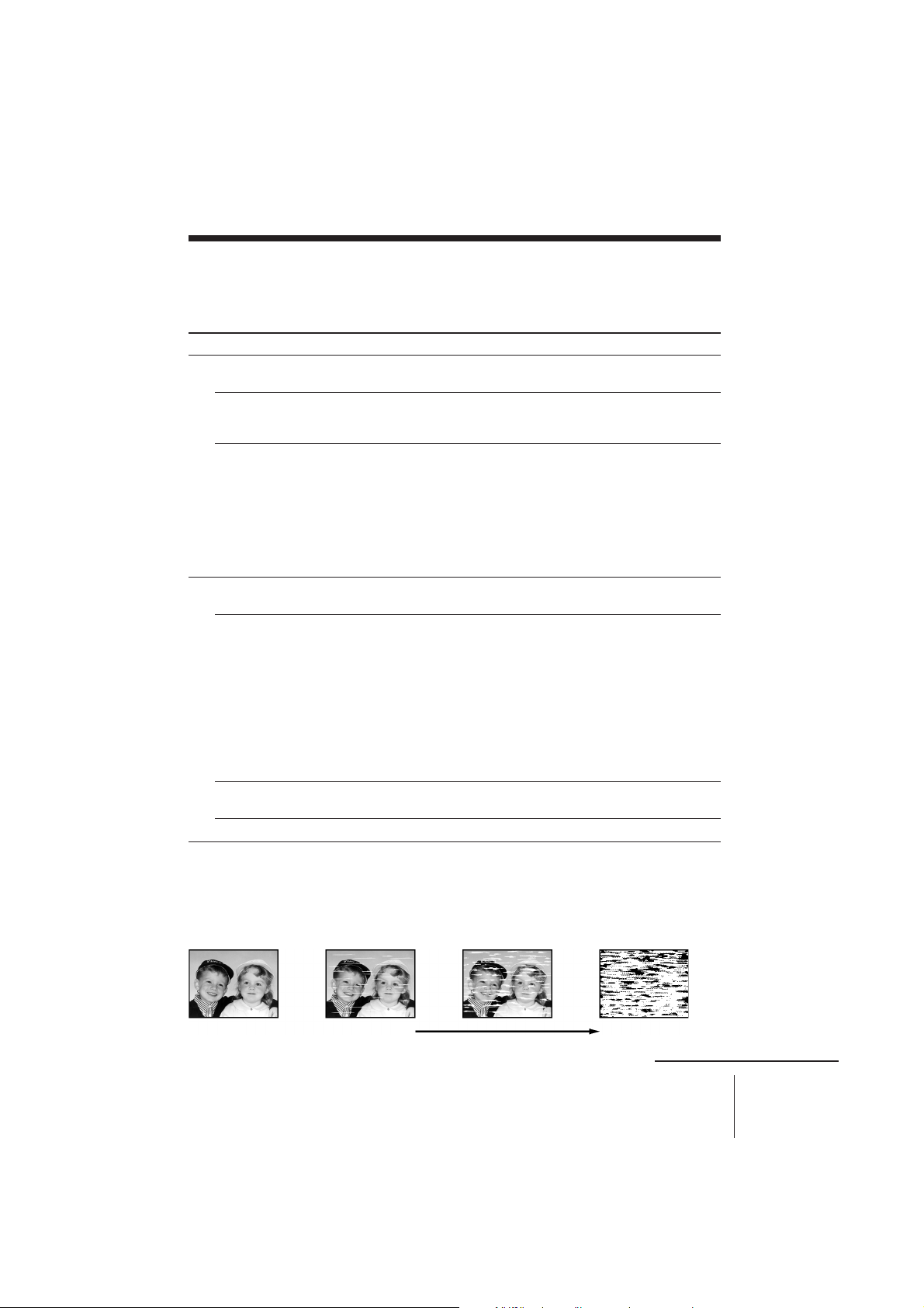
• The video heads are dirty (see below). Clean the video
heads using the Sony V-25CL video head cleaning
cassette. If this cleaning cassette is not available in
your area, have the heads cleaned at your nearest Sony
dealer (a standard service charge will be required). Do
not use a commercially available wet-type cleaning
cassette, as it may damage the video heads.
• The video heads may have to be replaced. Consult
your local Sony dealer for more information.
• Adjust the vertical hold control on the TV or monitor.
• The tape is defective. Use a new tape.
Symptoms caused by contaminated video heads
• Normal picture • Rough picture • Unclear picture
initial terminal
SLV-KA175PK/KA185PK/KF285PK 3-858-505-12 (1)
• No picture (or
black & white
screen appears)
continued
Additional Information
23
Page 24

Troubleshooting (continued)
Symptom
The tape starts playing as soon
as it is inserted.
The tape is ejected when you
press r REC.
Recording*Others
The microphone sound is
distorted.
A tape cannot be inserted.
The remote commander does
not function.
The unit needs to be cleaned.
* SLV-KA185PK/KF285PK only
Remedy
• The safety tab has been removed. To record on this
tape, cover the tab hole.
• Check that the safety tab has not been removed.
• The MIC VOL control is set too high.
• Check that a tape isn’t already in the tape
compartment.
• Make sure you are pointing the remote commander at
the remote sensor on the unit.
• Replace all the batteries in the remote commander with
new ones if they are weak.
• Clean the cabinet, panel, and controls with a dry soft
cloth, or a soft cloth slightly moistened with a mild
detergent solution. Do not use any type of solvent,
such as alcohol or benzine.
24
Additional Information
SLV-KA175PK/KA185PK/KF285PK 3-858-505-12 (1)
Page 25

Specifications
System
Format
VHS NTSC standard
Video recording system (SLV-KA185PK/KF285PK
only)
Rotary head helical scanning FM system
Video heads
Double azimuth four heads
Video signal
NTSC color, EIA standards
Tape speed
SP: 33.35 mm/s, playback only
Maximum recording (SLV-KA185PK/KF285PK
only)/playback time
2 hrs. in SP mode (with T-120 tape)
Fast-forward and rewind time
Approx. 4 min. 30 sec. (with T-120 tape)
Tuner section
RF output channel
VHF channel 3 or 4
Antenna
75-ohm antenna terminal for VHF/UHF
Inputs and outputs
LINE IN (SLV-KA185PK/KF285PK only)
VIDEO IN, phono jack (1)
Input signal: 1 Vp-p, 75 ohms, unbalanced,
sync negative
AUDIO IN,
phono jack (1) (SLV-KA185PK)
phono jack (2) (SLV-KF285PK)
Input level: 327 mVrms
Input impedance: more than 47 kilohms
LINE OUT
VIDEO OUT, phono jack (1)
Output signal: 1 Vp-p, 75 ohms, unbalanced,
sync negative
AUDIO OUT,
phono jack (1) (SLV-KA175PK/KA185PK)
phono jack (2) (SLV-KF285PK)
Rated output level: 327 mVrms
Load impedance: 47 kilohms
Output impedance: less than 10 kilohms
Microphone input
MIC IN (minijack) (1) (SLV-KA175PK)
MIC IN 1/2 (minijack) (2) (SLV-KA185PK/
KF285PK)
more than 3 kilohms, 1.84 mVrms
General
Power requirements
110 – 240 V AC, 50/60 Hz
Power consumption
12 W
Operating temperature
5°C to 40°C
Storage temperature
–20°C to 60°C
Dimensions
Approx. 355 × 102 × 283.5 mm (w/h/d)
including projecting parts and controls
Mass
Approx. 3.8 kg
Supplied accessories
Remote commander
RMT-V173 (1) (SLV-KA175PK)
RMT-V173A (1) (SLV-KA185PK/KF285PK)
Size AA (R6) batteries (2)
75-ohm coaxial cable with F-type connectors (1)
AC power cord (1)
Microphone (1)
Audio/video cable (3 phono to 3 phono) (1) (SLV-
KF285PK only)
Design and specifications are subject to change
without notice.
Additional Information
SLV-KA175PK/KA185PK/KF285PK 3-858-505-12 (1)
25
Page 26
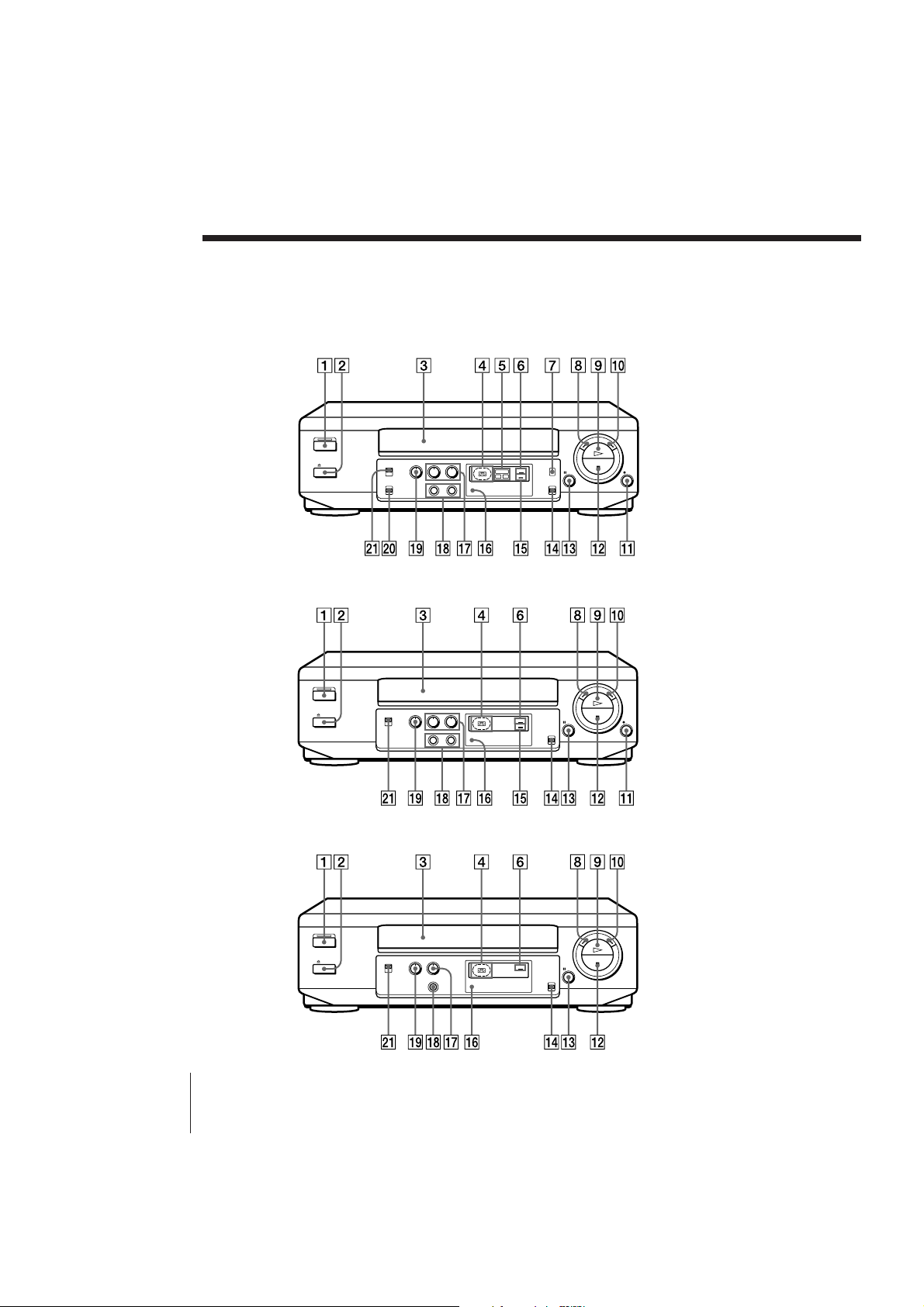
Index to parts and controls
Refer to the pages indicated in parentheses ( ) for details.
Front panel (SLV-KF285PK)
TV/VTR
HI-FI
REC
L R
Front panel (SLV-KA185PK)
Front panel (SLV-KA175PK)
26
Additional Information
TV/VTR
REC
TV/VTR
SLV-KA175PK/KA185PK/KF285PK 3-858-505-12 (1)
Page 27

1 POWER switch/indicator
2 § EJECT button (12)
3 Tape compartment
4 Tape operation indicators
5 HiFi L/R indicators (13) (SLV-
KF285PK only)
6 TV/VTR indicators (10)
7 AUDIO MONITOR button (13) (SLV-
KF285PK only)
8 0 3 REW button (12, 14)
9 · PLAY button (12)
0 ) # FF button (12, 14)
!¡ r REC button (21) (SLV-KA185PK/
KF285PK only)
!™ p STOP button (12)
!£ P PAUSE button (12)
!¢ PICTURE switch (12)
!∞ REC indicator (SLV-KA185PK/
KF285PK only)
!§ Remote sensor (5)
!¶ (SLV-KA175PK)
MIC VOL control (17)
(SLV-KA185PK/KF285PK)
MIC VOL 1/2 controls (17)
!• (SLV-KA175PK)
MIC IN jack (16)
(SLV-KA185PK/KF284PK)
MIC IN 1/2 jacks (16)
!ª ECHO control (17)
@º KARAOKE PON ON/OFF switch
(18) (SLV-KF285PK only)
@¡ KARAOKE ON/OFF switch (16)
continued
Additional Information
SLV-KA175PK/KA185PK/KF285PK 3-858-505-12 (1)
27
Page 28
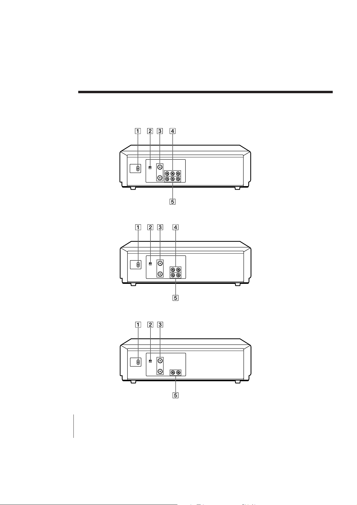
Index to parts and controls (continued)
Rear panel (SLV-KF285PK)
Rear panel (SLV-KA185PK)
Rear panel (SLV-KA175PK)
28
Additional Information
SLV-KA175PK/KA185PK/KF285PK 3-858-505-12 (1)
Page 29

1 AC IN connector
2 RF UNIT switch (10)
3 VHF/UHF IN/OUT connectors (9)
4 LINE IN AUDIO L/R/VIDEO jacks
(20) (SLV-KF285PK only)
LINE IN AUDIO/VIDEO jacks (20)
(SLV-KA185PK only)
5 (SLV-KF285PK)
LINE OUT AUDIO L/R/VIDEO
jacks (8, 20)
(SLV-KA175PK/KA185PK)
LINE OUT AUDIO/VIDEO jacks (7,
20)
continued
Additional Information
SLV-KA175PK/KA185PK/KF285PK 3-858-505-12 (1)
29
Page 30
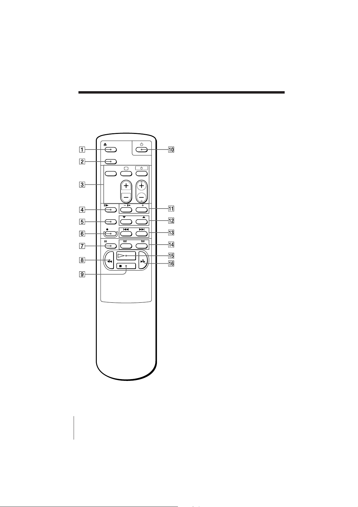
Index to parts and controls (continued)
Remote commander (e.g. SLV-KA185PK/KF285PK)
1 6␣ EJECT button (12)
2 TV/VTR button
3 TV buttons (Only for TV) (5)
TV/VIDEO
; (TV power)
u (Power standby)
VOL +/–
PROG (CH) +/–
4 7␣ FRAME button (14)
5 TRACKING AUTO/MANUAL
button (19)
6 r REC button (21) (SLV-KA185PK/
KF285PK only)
7 P␣ PAUSE button (12)
8 0␣ REW button (12, 14)
30
Additional Information
9 p␣ STOP button (12)
!º POWER switch
!¡ & SLOW +/– buttons (14)
!™ $/4TRACKING NORMAL/SLOW
STILL ADJUST buttons (19)
!£ =/+ AMS buttons (17)
!¢ 3/# SEARCH buttons (12, 14)
!∞ ·␣ PLAY button (12)
!§ )␣ FF button (12, 14)
SLV-KA175PK/KA185PK/KF285PK 3-858-505-12 (1)
Page 31

Index
A, B
Accessories supplied 4
Adjusting
picture 19
tracking 19
AMS searching 17
Antenna hookup 9
Audio track 13
Auto head cleaner 21
AV connection 7
C
Cleaning the video
heads 21, 23
Connecting
the unit and your TV 6
external antenna
connector 22
VHF/UHF band
mixer 22
D
Dubbing. See Editing
E, F, G
Echo 17
Editing 20
H, I, J
Hi-fi audio track 13
K, L
Karaoke sing-along 16
N
Normal audio track 13
O
OPC (Optimum Picture
Control) 19
P, Q
Picture adjustment. See
Adjusting
PICTURE switch 12
Playback 11
at various speeds 12, 14
frame-by-frame 14
slow motion 14
R
Recording 21
Reducing the playback
vocals 18
Remote commander 5
Rental tape 12
RF UNIT switch 10
S
Safety tab 21
Searching at various
speeds 14
SP mode 21
T, U, V, W, X, Y, Z
Tracking adjustment. See
Adjusting
M
Monitoring
during playback 13
Sony Corporation
SLV-KA175PK/KA185PK/KF285PK 3-858-505-12 (1)
 Loading...