

Sony sl-hf600 Owner's Manual
SONYe
VIDEO CASSETTE RECORDER
SL-HFQOO
OPERATING INSTRUCTIONS TABLE OF CONTENTS
...............................................................................
........................................................................
Warning
2
..............................................................................
Before operating the unit. please read this manual Precautions
2
thoroughly. and retain it for future reference
.
Features
3
ponnections
..................................
Antennalcable and
TV
connection
4
Connection to a
TV
set with videolaudio
OWNER'S RECORD
....................................................................
input jacks
7
The model and serial number of your set are located at
..........................................
Connecting a color monitor
7
the
rearm
the
number
in the
'pace provided Connection to an audio system
.......................................
8
..............................................................
Refer
these
numbers
whenever
you
call
up0n power connection
9
your Sony dealer regarding this product
.
Settino the clock
................................................................
9
.
................................................................
Adjusting the
TV
10
Model No . SL-HF900 Serial No
.
Selecting channels
............................................................
1
Presetting channels
..........................................................
12
lnsertinglejecting cassettes
............................................
12
..........................
Opening and closing the JOG dial door
13
........
About the conventional and Beta hi-fi audio track
13
Fperation4
.
..-
....................................................
Recording
TV
programs
14
To view one
TV
program while recording another
.....
15
Receivinglrecording Multichannel
TV
Sound
.........................................................
(MTS) broadcasts
15
Playback
.............................................................................
16
.........................................................................
Auto play
17
Betascan. Beta SkipScan
.............................................
17
Various playback.modes
..............................................
17
Playback using the JOG dial and the SHUTTLE
.................................................................................
ring
18
.................................................
Remote control operation
19
Timer-activated recording
................................................
22
Setting the timer
............................................................
22
Every weeklevery day timer recordings
.......................
24
Quick timer recording
...................................................
25
Use of the time counter
.....................................................
26
Tape returnltape return play
.........................................
26
Index function
....................................................................
26
.................................................
Beta hi-fi audio recording
29
................................................
FM simulcast recording
30
6wDrrr
bPrn
hl#b
PCM recording and playback
31
...........................................
1
.
Camera recording
..............................................................
32
..............................................
This
unit
can
be used with
any
video
cassette
tapes
Frame by frameshooting
32
......................................................................
having the mark
lB
.
Editing tapes
33
..................................................
Audio and video insert
35
........................................
It
is
compatible
with
the
'land
lBn
recording
and
Automatic assemble editing
38
.........
....................................
playback
and
will play
back
tapes
recorded
in
Tape editing techniques
..
40
the
mI
format
.
........................................
Using the Sony control system
43
@-I
..................
.
ocation and function of parts and controls
46
Speciflcations
...........-,....................................................
51
.,
'
.
.
Troubleshooting
..........,......................................................
52
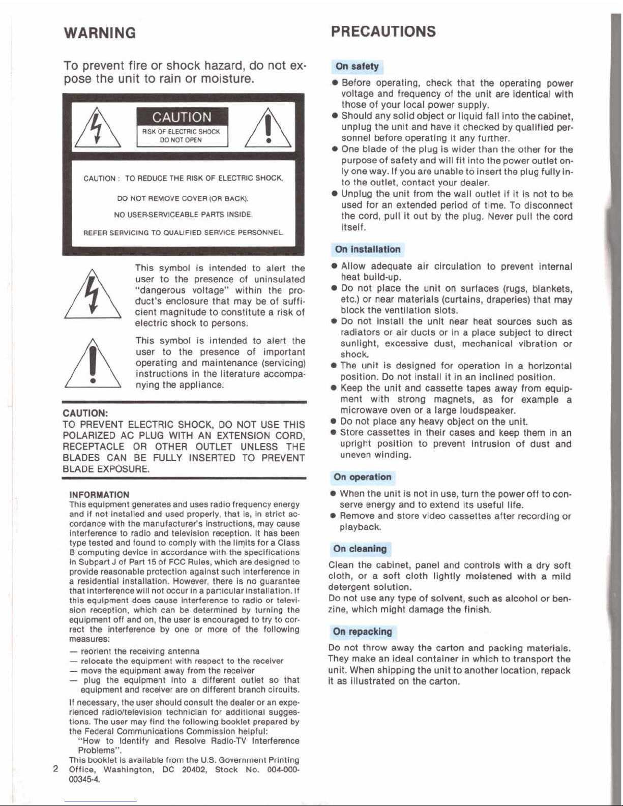
WARNING
PRECAUTIONS
To
prevent
fire
or
shock
hazard,
do
not
ex-
pose
the
unit
to
rain
or
moisture.
RISK
OF
ELECTRIC
SHOCK
AFA
CAUTION
:
TO
REDUCE
THE
RISK
OF
ELECTRIC
SHOCK
M)
NOT
REMOVE
COVER
(OR
SACK).
NO
USERSERVICEABLE
PARTS INSIDE.
REFER
SERVlClNQ
TO
WALlFlEO
SERVICE
PERSONNEL
mis symbol is lntended to alert the
user to the presence of uninsulated
"dangerous voltage" within the product's enclosure that mav
be
of suffl-
/
\
cient magnltude to constitute a risk of
electric shock to persons.
This symbol is lntended to alert the
user to the presence of important
operating and
malntmce (servicing)
instructions in the literature accompanying the appliance.
CAUTION:
TO PREVENT ELECTRIC SHOCK,
DO
NOT USE THIS
POLARIZED AC
PLUG
WITH AN EXTENSION CORD.
RECEPTACLE OR OTHER OUTLET UNLESS THE
BLADES CAN BE FULLY INSERTED TO PREVENT
BLADE EXPOSURE.
INFORMATION
Thls equlpment generates and uses radio frequency energy
and
If
not Installed and used orooerlv. that is. In strlct ac-
cordance
w~th the manufactuier's instructions, may cause
lnterference to
radlo and
television
reception. It has
been
type tested and found to comply with the ilqits for a Class
B
comoutino device in accordance with the soeclflcations
in subpart For Part 15 of
FCC
RUIW,
whichire designed to
provide reasonable prolectlon against such lnterference In
a resldentlal Installation. However, there Is no auarantee
that interference
wlll
not occur in
a
particular
instiliatlon.
If
this equipment does cause lnterference to radlo or telwlElon
reception,
whlch can
be
determined by turnlng the
equipment off and on, the user
Is encouraged to try
to
cor-
rect the lnterference by one or more of the
following
measures:
-
reorlent the receiving antenna
-
relooate the equlpment with respect to the receiver
-
move the equipment away from the receiver
-
plug the equipment into a different outlet
80
that
equipment and receiver are on
different
branch circuits.
if
necessary, the user should consult thedealer or an expe-
rienced
radioltelevlsion techniclan for addltional sugges-
tions. The user may
flnd the following booklet prepared by
the Federal Communications
Cornmisalon helpful:
"How to Identify and Resolve
Radi0.N interference
Problems".
Thls booklet is available from the U.S. Government Prlnting
2
Offlce,
Washington,
DC
-2,
Stock No.
004-000
003454.
eratlng, check that the operating power
voltage and frequency of the unit are
ldentlcal wlth
those of your local power supply.
Should any solld object or llquld fall into the cabinet,
unplug the unlt and have it checked by
quailfled personnel before operating it any further.
One blade of the plug Is wider than the other for the
purpose of safety and
wlll flt into the power outiet only one way. if you are unable to insert the plug fully into the outiet, contact your dealer.
Unplug the unit from the wall outlet If
It
is not to be
used for an extended perlod of time. To disconnect
the cord, pull
It out by the plug. Never pull the cord
itself.
Allow adequate alr clrcuiatlon to prevent Internal
heat buildup.
Do not place the unit on surfaces (rugs, blankets,
etc.) or near materials (curtains,
draperies)
that may
block the ventllation slots.
Do
not Install the unit near heat sources such as
radiators or
air ducts or in a place subject to direct
sunlight, excessive dust, mechanical
vibration
or
shock.
The unit is deslgned for operation In a horizontal
posltlon. Do not install It In an lncllned position.
Keep the unlt and cassette tapes away from equipment with strong magnets, as for example a
microwave oven or a
large loudspeaker.
Do not place any heavy object on the unit.
Store cassettes In their cases and keep them In an
upright position to prevent intruslon of dust and
uneven wlndlng.
em
When the unit Is not In use, turn the power off to conserve energy and to extend
Its useful Ilfe.
Remove and store vldeo cassettes after recording or
playback.
I(ls
Clean the cablnet, panel and controls wlth a dry soft
cloth, or a soft cloth lightly moistened wlth a
mild
detergent solutlon.
Do not use any type of solvent, such as alcohol or ben.
zlne, which might damage the finlsh.
Do not throw away the carton and packing msterlals.
They make an ideal container in which to transport the
unlt. When
shipplng the unit to another
location,
repack
It
as Illustrated on the carton.
r
WHAT
IS
BETA
HI-FI
RECORDINQ?
In conventlonal
recordlng, audlo signals are recorded
on the audlo track and video
slanals on the video track.
In Beta hl-fl recording, audio
sl&als are recorded on the
video track together with the video signals
uslng
2
rotary vldeo heads.
The Beta hi-fi audio
slgnals are frequency-modulated
and recorded on
2
channels, so that you can record a
etereo program with sound quallty far superior to that of
the
conventlonal audlo recordlng.
I
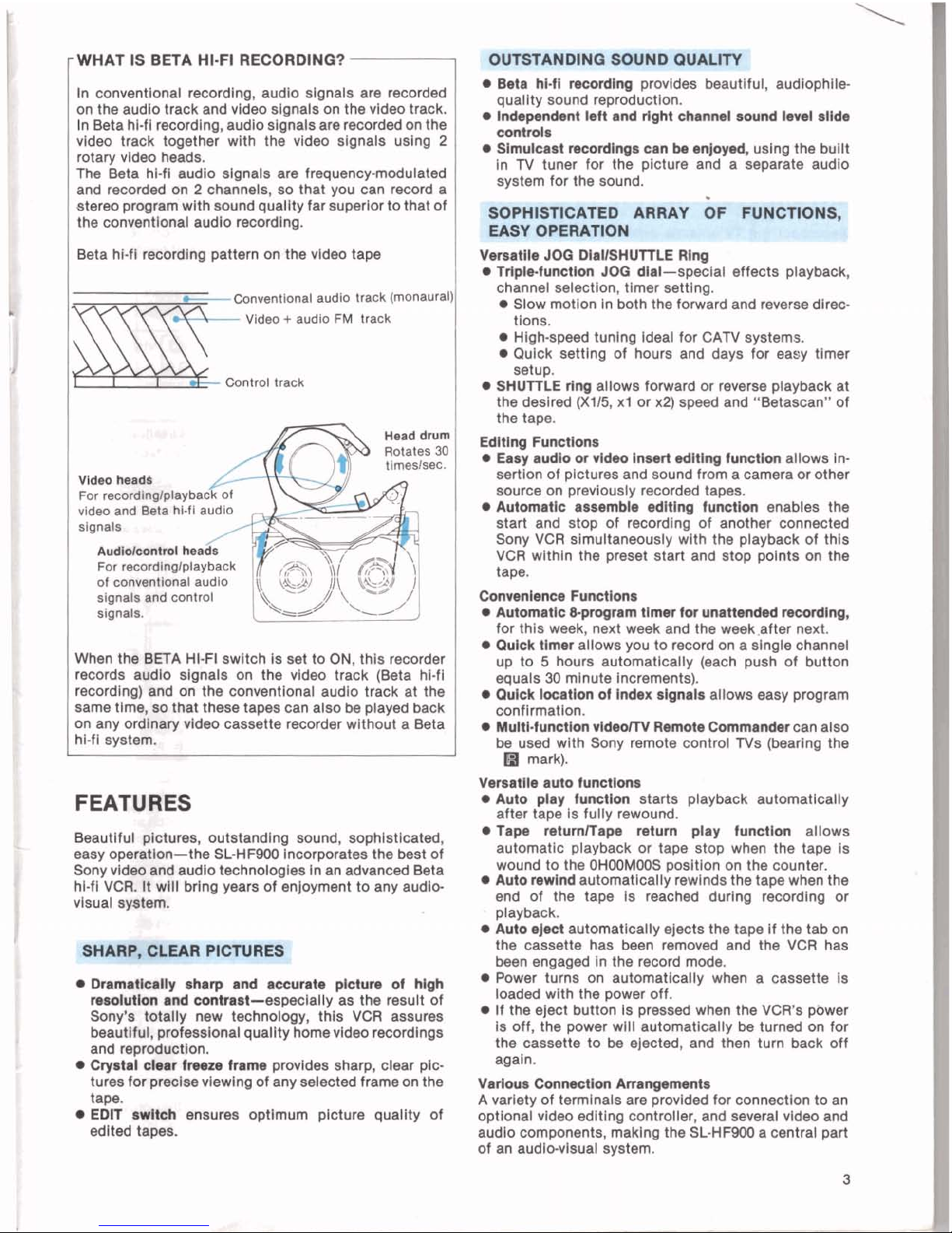
Beta hi-fi recording pattern on the vldeo tape
Conventlonal audlo track (monaural
Video + audio
FM
track
\
Control track
Head
drum
Rotates
30
tirneslsac.
Vld.0
head$
AudloRontroi hea
For
recordlnglplayback
of conventtonal audlo
signals and control
signals.
When the %ETA HI-FI swltch is set to
ON,
this recorder
records audio
slgnals on the vldeo track (Beta hl-fl
recordlng) and on the conventlonal audio track at the
same time,
ao
that these tapes can also be played back
on any
ordlnaty vldeo cassette recorder without a Beta
hi-fi system.
FEATURES
Beautiful pictures, outstandlng sound, sophlstlcated,
easy operatlon-the SL-HFWX)incorporstes the best of
Sony
vldw and audlo technoloples In an advanced Beta
hl-fi~v~~
It
wHl
brlng years ofenjoyment to any audio-
visual
sy8tem.
SHARP, CLEAR P
RES
1
!
OUND QUAL~
Beta hl-11 noordlng provldes beautlful, audiophile
quallty sound
reproductlon.
Indep.nd.nt
I&
and right channd
sound
Id
slMr
oonbo1a
Slmulcart maordlngr can k enjoyed, uslng the bullt
in N tuner for the picture and a separate audlo
system for the sound.
.
Versatile
JOG
DIaUSHUTTLE
Rmy
Triplr-functlon
JOB
dlal-speclai effects playback,
channel selection, timer setting.
Slow motion in both the forward and reverse dlrections.
Hlgh-speed tunlng ideal for CAN systems.
Qulck setting of hours and days for easy tlmer
Dnnuthlly sharp and accurate pklum of hlgh
mohifbn
md
contraat-especially
as the result of
Sony's totally new technology, thls VCR assures
beautlM, prefessional quallty homevldeo recordings
and
reprodudon.
Qyatal
oklr
hwze
frama provldas sharp, clear plcturea forpreclse vlewlng of any selected frame on the
tape.
EDIT
ndteh
ensures optimum picture quallty of
ed~ted tapes.
setup.
SHUTTLE ring allows forward or reverse playback at
the desired
(X115. xl or x21 swed and "Betascan" of
the tape.
Edltlna Functions
EaG
audlo
or
v1d.o Inawl ditlng function allows In-
sertion of
Dictures and sound from a camera or other
source
~n~~revlousl~ reoorded tapes.
Automatic
aaaamble edltlng functlon enables the
start and stop of recordlng of another connected
Sony VCR
slmultaneousiy wlth the playback of thls
VCR within the preset start and stop points on the
tape.
Cornenlance
Functions
Automalc
&pmgnm
tlmer
tor
unattended
mording,
for this week, next week and the week.after next.
Quick tlmar allows you to record on a sinale channel
up to
5
hours aut&natlcally (each push of button
equals
30
minute increments).
Quick locatlon of index -nab allows easy program
confinnatlon.
a
Mull-function
vld.orm
Remote
Commander can also
be used with Sony remote control Ns
(bearing the
H
mark).
Vrmalle auto functlona
Auto play function starts playback autornatlcally
after tape is
fully rewound.
.Tap. mturnlTap. return play functlon allows
automatic playback or tape stop when the tape is
wound to the
OHOOMOOS positlon on the counter.
Auto rewind automatlcally rewinds the tape when the
end of the tape is reached
durlng recording or
playback.
Auto
rJoct
automatlcally ejects the
tape
If the tab on
the cassette has
been
removed and the VCR has
been engaged
In the record mode.
Power turns on automatically when a cassette Is
loaded with the power off.
If the eject button Is pressed when the VCR's pbwer
Is off, the power will autornatlcally be turned on for
the cassette to
be
ejected, and then turn back off
agaln.
Varlour Conlmtlon
Amng.Nntt
A varlety of
terminals
are provlded for connectlon to an
optlonel video edlting controller, and several vldeo and
audlo
comDonents, maklna the SL-HFWX) a central Dart
Befon maklng wnnectlol
Turn off the
TV.
Connect the ac power cord after all the connectlons of the vldeo cassette recorder and the
TV
have been
completed.
Make connectlons firmly. A loose
connection
may cause a distorted plcture.
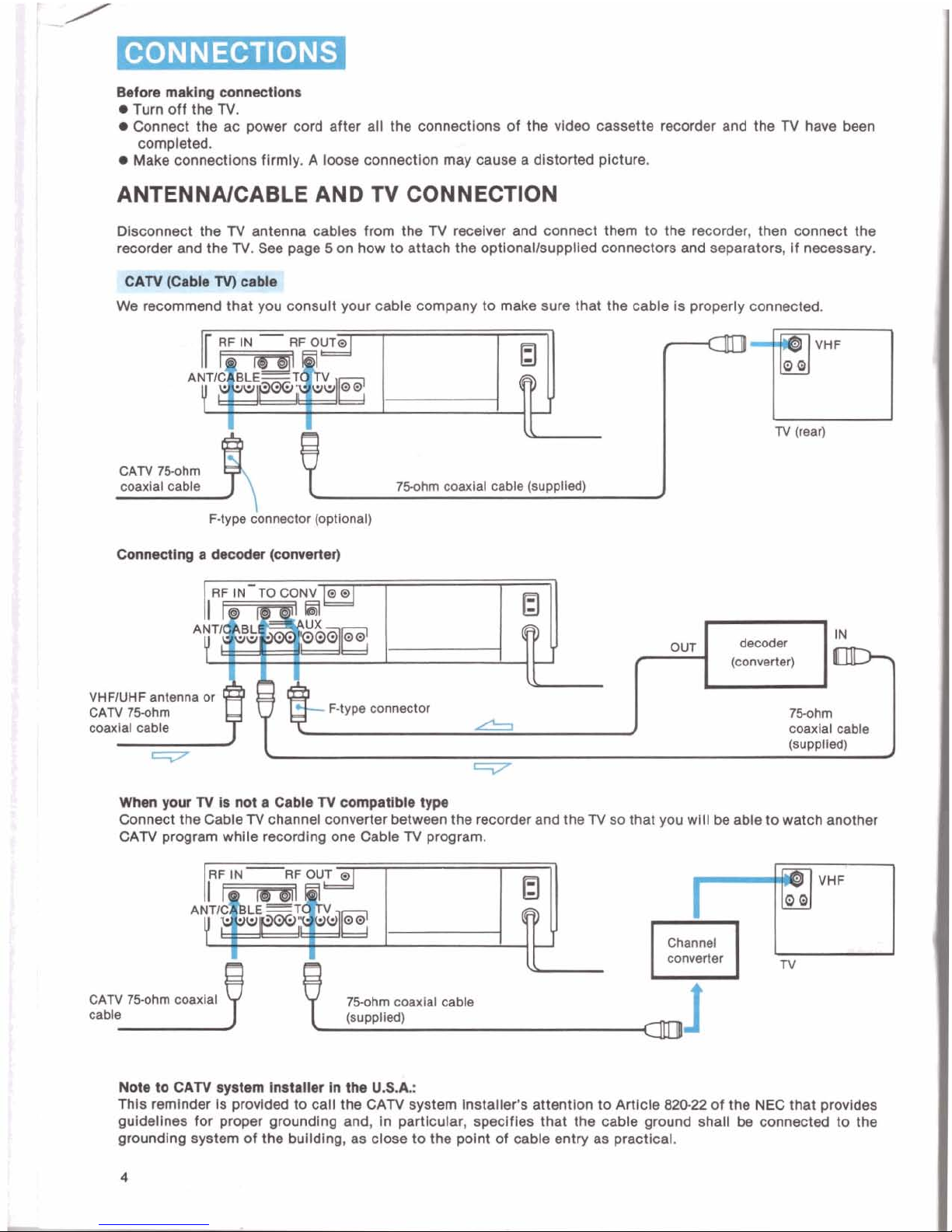
ANTENNAICABLE AND
TV
CONNECTION
Disconnect
the TV antenna cables from the TV recelver and connect them to the recorder, then connect the
recorder and the
TV.
See
page 5 on how to attach the optlonallsupplled connectors and separators, If necessary.
'#hl
(Cable
TV)
able
-
-
>-
--
-
We
recommend that you consult your cable company to make sure that the cable is properly connected.
T!II
N
(rear)
F-type
donnector (optional)
VHFlUHF
antenna or
CATV
750hrn
F-type connector
Whan
your N la
not
a
Cable N wmptlbk
type
Connect the CableTV channel converter between the recorder and the N so that you wlll be able to watch another
CAN program while
recordlng one Cable
TV
program.
75.0hm
coaxial
Note to CAN
syetem Installer In the
U.Sk
This reminder is provlded to call the CATV system Installer's
attention
to Artlcle
820-22
of the NEC that provldes
guidelines for proper groundlng and,
In
particular,
speclfles that the cable ground shall
be
connected to the
groundlng system of the bulldlng, as close to the polnt of cable entry as practical.
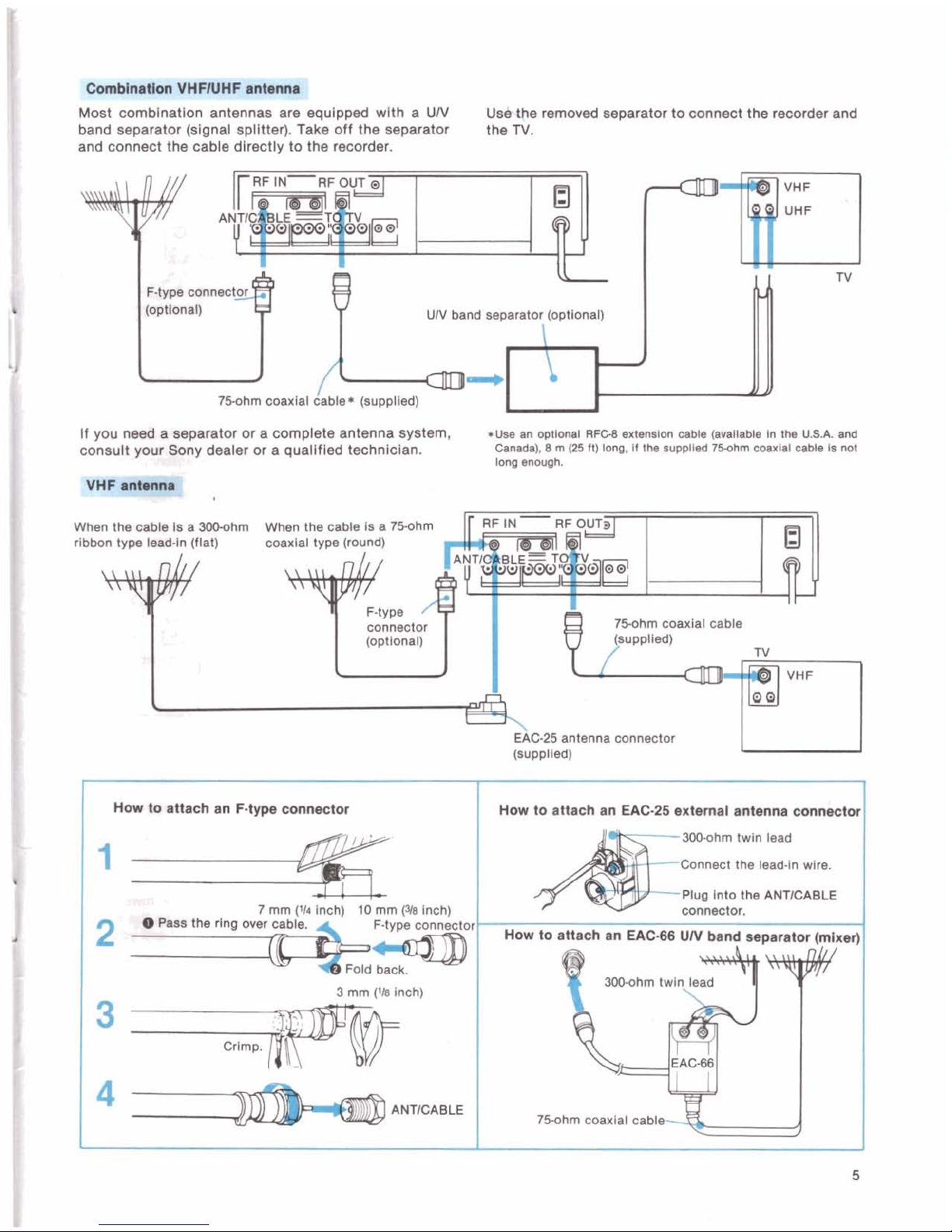
@@blnatton
VHFIUHF
antenm
Most comblnat~on antennas are equlpped wlth a
UN
Uwe removed separator to connect the recorder and
band separator
(slgnal splltter). Take
off
the separator
the
N.
and connect the cable dlrectly to the recorder.
If you need a separator or a complete antenna system,
*use
an
optional
RFCB
enermlon
cable
(wa11abie
In
~IW
U.S.A.
WUI
consult
yow
SOny
dealer
or
a quallfled technlclan.
Canada),
8
rn
(25
R)
long,
if
the auppllsd
75ahm
ooaxial
cable
is
not
long
enough.
300ohm When the
hrn coaxial cable
EAC-25
antenna connector
(supplled)
How
to
attach an
F-type
connector
How
to
attach an
EAC-25
external antenna connector
mhrn twin lead
Connect the lead-in
wlre.
3
rnm
(U
inch)
750hrn coaxlal cable
~WYP-
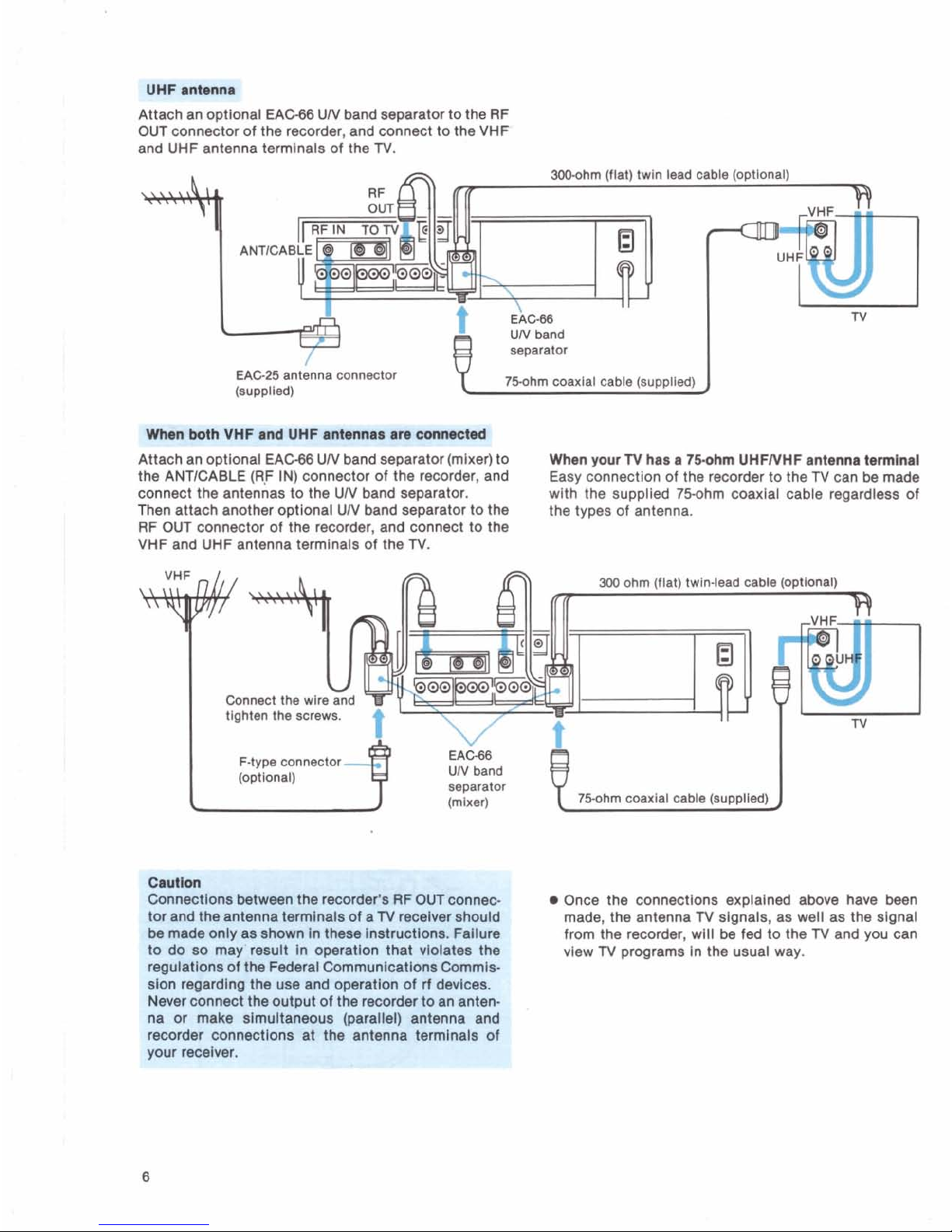
Attach an optlonal
EACe6
UN band separator to the RF
OUT connector of the recorder, and connect to the VHP
and UHF antenna terminals of the
TV.
mhm iflatl twin
EAG25
antenna connector
(suwlledl
.
.
UN
band
lead cable (optional)
-
separator
75ohm
coaxla1 cable (supplied)
Attach an optlonal
EAW
UN band separator (mlxer) to
When
your
N
ha8
r
7-m
UHFNHF
antenna tennlnal
the ANTICABLE (RF IN) connector of the recorder, and
Easy
connection of the recorder to the
TV
can
be
made
connect the antennas to the UN
band
separator.
wlth the
supplled 75ohm coaxlal cable regardleas of
Then attach another optlonal UN band separator to the
the types of antenna.
RF OUT connector of the recorder, and connect to the
VHF and UHF antenna
termlnals of the
TV.
Connect thew
F-type connector
Crutton
Connections between the recorder's
RF
OUT connec-
Once the connections
explained
above have been
tor and the antenna
terminals of a
TV
recelver should made, the antenna
TV
signals, as well as the signal
be
made only as shown In these lnstructiona. Fallure
from the recorder, wlli be
fed
to the
TV
and you can
to do so may result
In operation that violatea the
vlew
TV
programs in the usual way.
regulations of the Federal
Communlcatlons Commls-
sion regarding the use and operation of
rf
devlces.
Never connect the output of the recorder to an antenna or
make
simultaneous
(parallel) antenna and
1
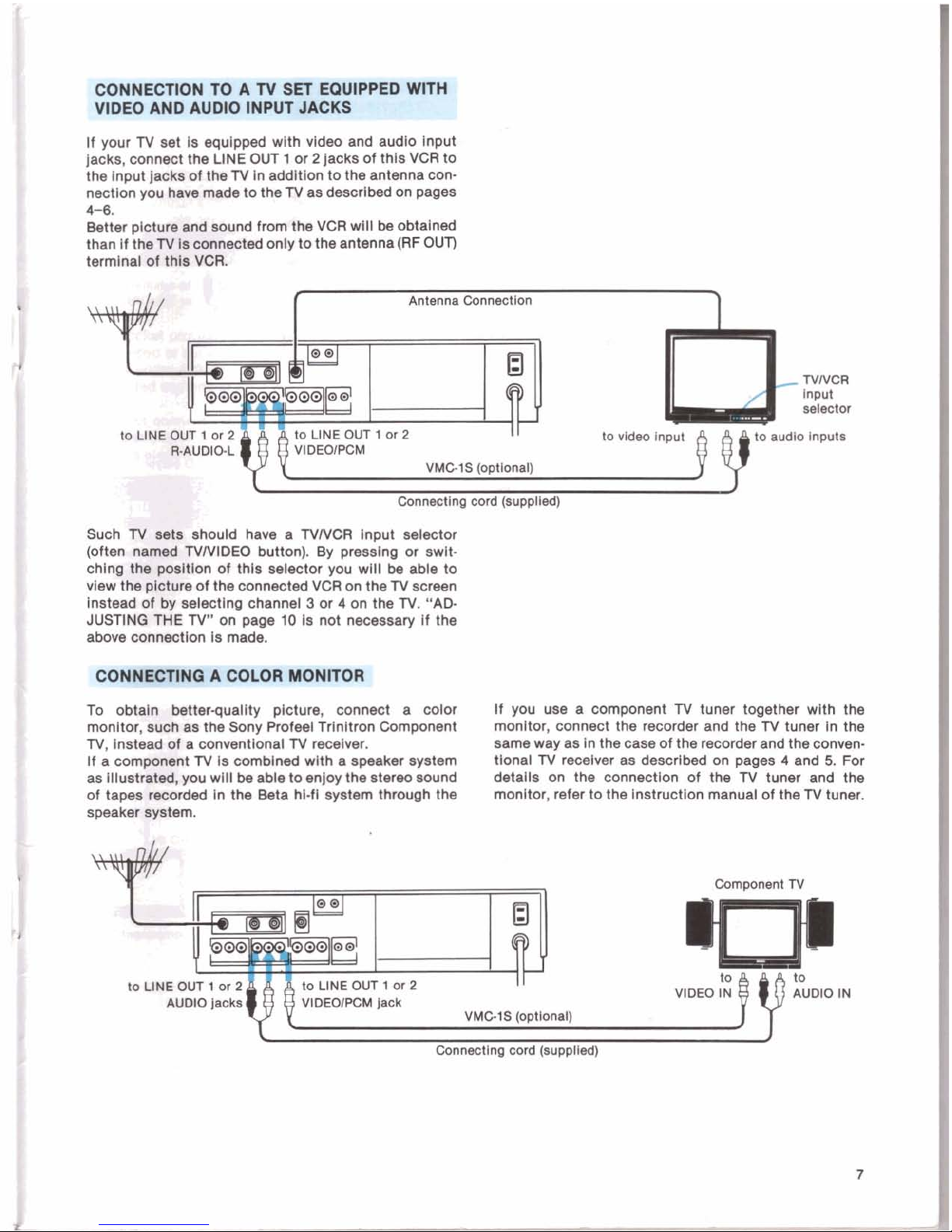
CONNECTION TO A TV
SET
EQUIPPED
WIT#
waEem.Alrsra
Mu-
if your TV set
Is
equipped with video and audio input
jacks, connect the
LINE OUT 1 or 2 jacks of this VCR to
the lnput
Jacks of the TV in addition to the antenna connection you have made to the TV as described on pages
4-6.
Better plctw
and
sound from the VCR will
be
obtained
than
If thel'tflsoonnected only to the antenna(RF OUT)
terminal
of
tMa
VCR.
--
Canneetlng
wrd
(supplied)
Such
N
satr
should have a TVNCR lnput selector
(often
nuac)rl
NNIDEO button). By presslng or swit-
chlng
the
podtion
of
this selector you will
be
able to
view the ploture of the connected VCR on the TV screen
instead
of by selecting channel 3 or 4 on the
N.
"AD
JUSTlNO
THE
TV"
on page
10
Is not necessary if the
above
oonnection is made.
To
obtsln
Wterquailty picture, connect a color if you use a component
TV
tuner together with the
monitor, such as the
Sony Profeel Trinltron Component monitor, connect the recorder and the TV tuner in the
TV, instead
of
a conventional N recelver.
same way as in the case of the recorder and the conven.
If a compomt N is comblned with a speaker system tlonal TV recelver as
described
on pages 4 and
5.
For
as
iilustrrrted,you wlll
be
able to enjoy the stereo sound details on the connection of the N tuner and the
of tapes
mcorded
in the Beta hl-fl system through the monitor, refer to the Instruction manual of the TV tuner.
speaker
system.
toWEO~1or2
AUDIO
jacks
Component
TV
jack
VMGIS
(opttonal)
.-
.'"I
".r
AUDIO
IN
Conoeoting
cord
(suppiled)
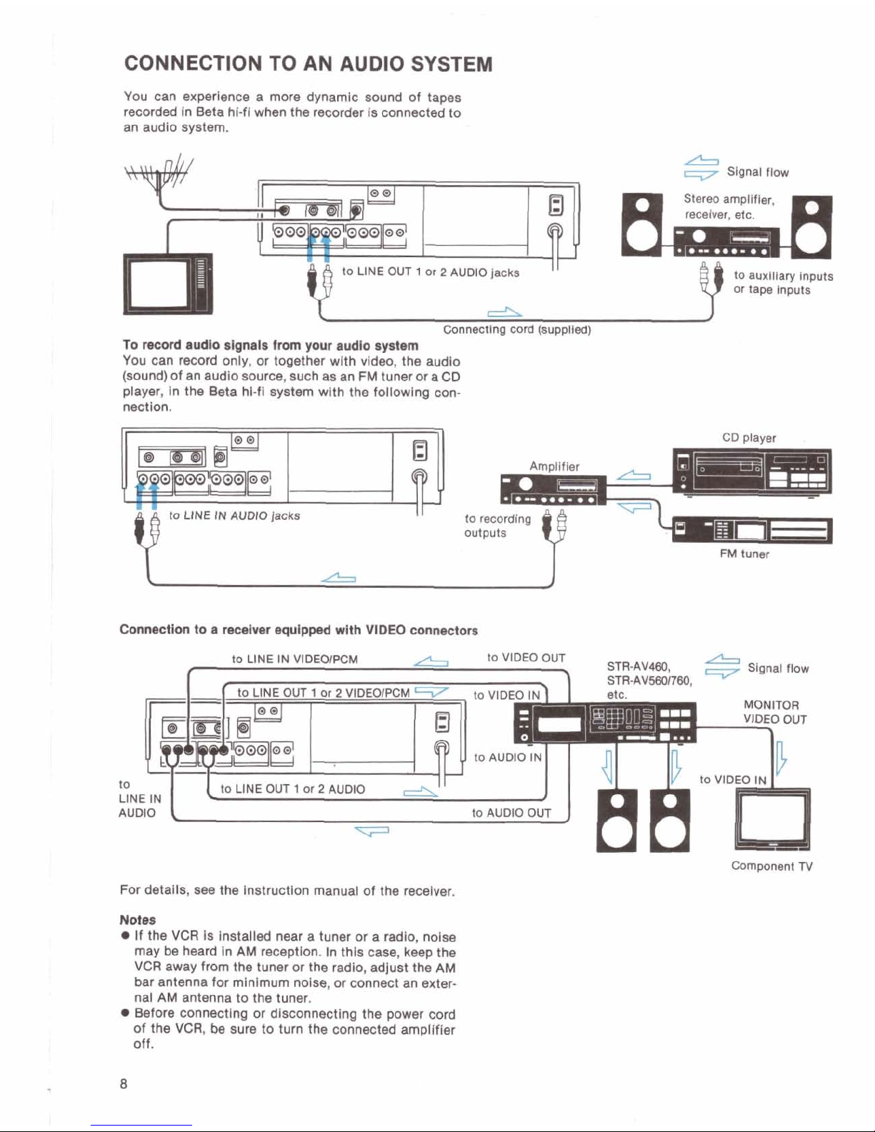
CONNECTION TO AN AUDIO SYSTEM
You can experience a more dynamic sound of tapes
recorded
In Beta hi-fi when the recorder Is connected to
an audlo system.
1
or 2 AUDIO jacks
I
I
e
Slgnal Row
Stereo ampllfler,
dl
Conneotlna cord isu~~lled)
-
.
..
To
ncord
audio signair
from
your
audlo
syahm
You can record only, or together wlth video, the audlo
(sound) of an audio source, such as an
FM
tuner or a
CD
player, In the Beta hl-fl system wlth the following connectlon.
A
to LINE IN AUDIO jacks
i
I
to
auxlllary Inputs
or
tape inputs
Y
to recording
OUtpUtS
FM
tunm
&
Connmctlon
to a
mceivar
equipped wlth
VIDEO
connectom
/L.
STR-AV460,
-
Signal flow
STR-AVSBOnBO,
Component
N
For detalls, see the lnstructlon manual of the receiver.
Not..
If the
VCR
Is Installed near a tuner or a radio, nolse
may be heard In
AM
reception. In this case, keep the
VCR
away from the tuner
or
the radio, adjust the
AM
bar antenna for minimum noise, or connect an exter-
nal
AM
antenna to the tuner.
Before
connecting
or dlsconnecting the power cord
of the
VCR,
be
sure to turn the connected amplifier
off.
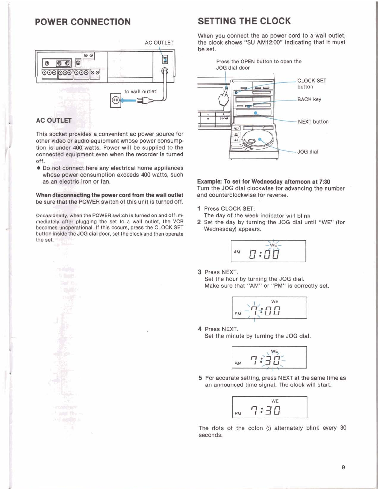
POWER CONNECTION
AC
OUTLET
to wall outlet
AC
This
wfht
provtdes
a
convenient
ac power source for
other
Wldw
or
audio equipment whose power consump-
tlon
Is
under
400
watts. Power will
be
suppiled
to
the
connerfiad
equipment
even when the recorder is turned
off.
Do
mt
connect hem any electrloai home appliances
whew power conaumptlon exceeds
400
watts, such
as
an eMc iron or fan.
When
dbmmm&lng
the power
cord
from
the wall outlet
be
sure
that
the POWER switch of this unit Is turned off.
occaetondiy, when the POWER swltch is turned on and off im-
madlately am plugging the set to a wall outlet, the VCR
becomes on@peratlonal. If this occurs, press the CLOCK
SET
button
hraMetfm
JOGdlai door, set theclockand then operate
the
set.
*!
y-
5.
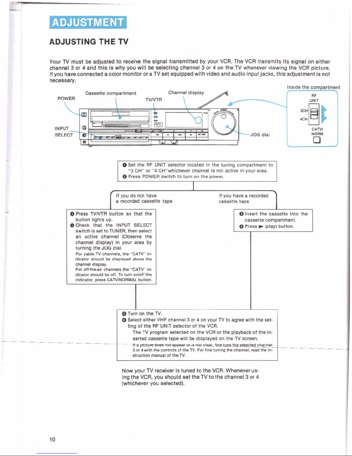
SETTING THE CLOCK
When you connect the ac power cord to a wall outlet,
the clock shows
"SU AM12:MY' indicating that it must
be set.
Press the
OPEN
button to open the
JOG
dlal door
CLOCK
SET
button
BACK key
NEXT button
JOG
dial
Example: To set
fw
Wednesday
afternoon
at 7:30
Turn the JOG dial clockwise for
advancing
the number
and counterciockwlse for reverse.
1
Press
CLOCK
SET.
The day of the week Indicator will blink.
2
Set the day by turning the JOG dial until "WE" (for
Wednesday) appears.
3 Press NEXT.
Set the hour by turning the JOG dial.
Make sure that "AM" or
"PM" Is correctly set
4
Press NEXT.
Set the minute by turnlng the
JOG
dial.
'1.
5
For accurate setting, press NEXT at the same time as
an announced time
slgnai. The clock will start.
The dots of the colon
(:)
alternately bllnk every
30
seconds.
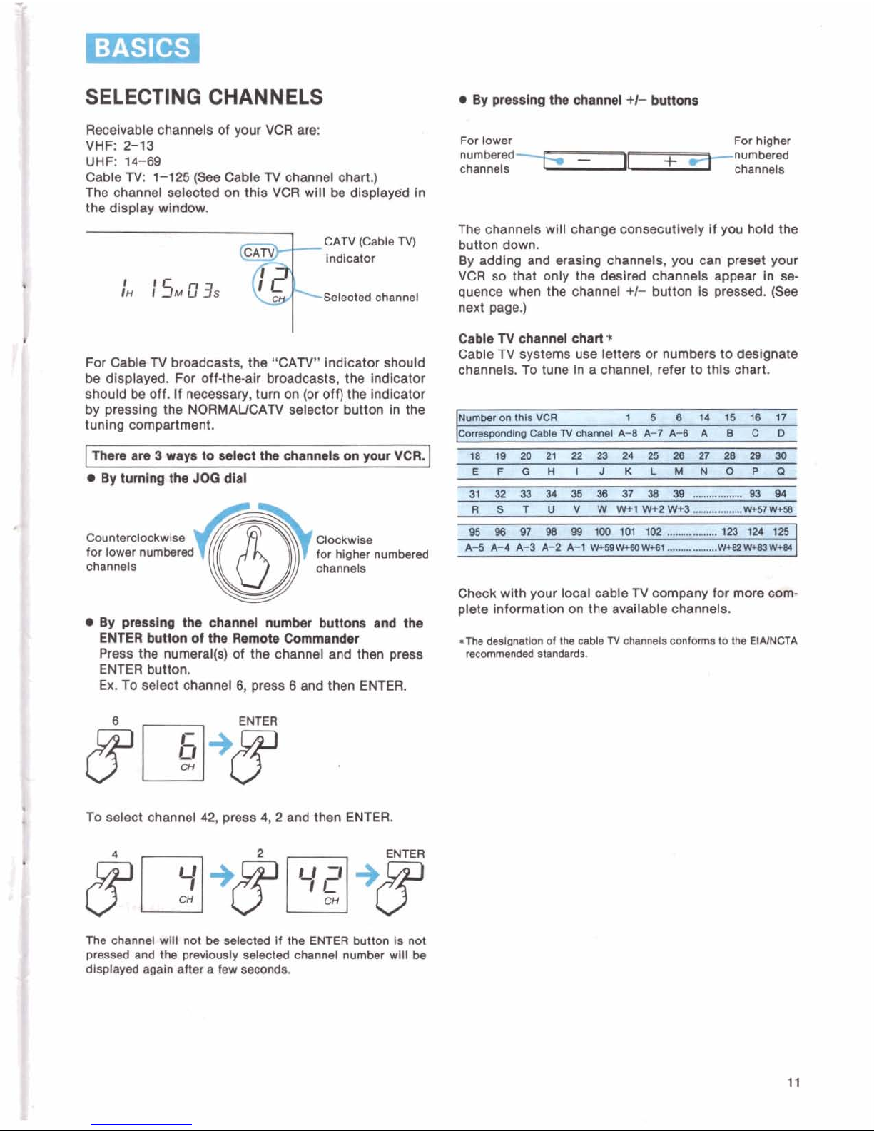
ADJUSTING
THE
N
Your N must
be
adjusted to receive the signal
transmitted
by your
VCR.
The
VCR
transmits its signal
on
either
channel
3
or 4 and thls
is
why you will
be
selecting channel 3 or 4 on the N whenever vlewlng the
VCR
pictura
if you have connected a color monitor or
a
TV
set equipped wlth video and audlo Input jacks, this adjustment is
not
necessary.
Cassette compartment Channel
dlsplay
A
WWER
NNTR
\
JOG
dial
Set
the
RF
UNlT selector located In the tunlng compartment to
"3
CH" or
"4
CHwhlchever channel Is not actlve In your area.
0
Press POWER swltch to turn on the power.
I
If you do not have
a recorded cassette
tape
0
Press
TVMl
button so that the
button lights up.
dCheck that the INPUT SELECT
-
switch
I8
set toNNER, then select
an
actlve channel (Obssrve the
channel display) In your area by
turning the
JOO
dlal.
For
oable N chanrmls,
the
"CAN"
ln-
dlcatw lhould b dl.played
ah
the
ohm1
dllolav.
For
off.m&lr
ihanmla the
"CAN'.
In.
dlator Should
b#
OW.
TO
turn
NOll
the
If you have a recorded
cassette tape
@Insert the cassette into the
cassette
compartment.
0
Press b (play) button.
1
I
~um
on the
N.
Seleot elther
VHF
channel 3 or 4 on your N to agree with the set-
ting of the RF
UNlT selector of the
VCR.
The N program selected on the
VCR
or the playback01 the In-
seried
camtte tape wlil
be
displayed on the N screen.
--
~0~1,~~hhae~ed
channel
3
or 4 wlth th oontmls
of
theN. Fw flne tunlnp
the
channel,
mad
the
In-
st~otlon
manual
of
th,
N.
Now your N recdver is tuned to the
VCR.
Whenever us-
ing the
VCR,
you should set the N to the channel 3 or
4
(whichever you selected).
SELECTING CHANNELS
Receivable channels of your VCR are:
VHF:
F13
UHF:
14-69
Cable
TV:
1-125
(See
Cable N channel chart.)
The channel selected
on
thls VCR will be dlsplayed In
the dlsplay wlndow.
For Cable N broadcasts, the "CAN" lndlcator should
be
dlsplayed. For off-the-alr broadcasts, the Indicator
should
be
off. If necessary, turn on (or off) the Indicator
by
presslng the NORMAUCAN selector button In the
tunlng compartment.
I
Thore
are 3 wava to select the channels
on
wur
VCR.
I
By
turnlng the
JOQ
dial
Clockwise
for lower
numl
for hlgher numbered
channels channels
By
pmsslng the channd number bunons and the
ENTER button
of
tho
Remob Commandnr
Press the numeral(s) of the channel and then press
ENTER button.
Ex.
To select channel
6,
press 6 and then ENTER.
To select channel
42,
press
4,2
and then ENTER.
The
ohand wHI not
be
selected
if
the
ENTER
button Is not
preseed
and
the
previously
selected channel number
wlll
be
dlsplayed again alter a few seconds.
By
prerrlng the channel
+I-
bunons
For
lower For hlgher
numbered-
-
I
+c
numbered
channels
chanwls
The channels
will
change wnsecutlvely if you hold the
button down.
By adding and
eraslng channels, you can preset your
VCR so that only the desired channels appear in
as
quence when the channel
+/-
button is pressed.
(See
next page.)
Cable
N
channel chart*
Cable N systems use letters or numbers to dealgnate
channels. To tune In a channel, refer to thls chart.
0s
m
W
98
80
180
101
rn
,,.-.,.a.
280
ta4.
lpb
A-S
k4
A-3
A-
kt
W+WWYW(,
...--.
.
....
WtUmIYM,
Check wlth your local cable
TV
company for
mqre(i~~1-
plete lnformatlon on the
available
channels.
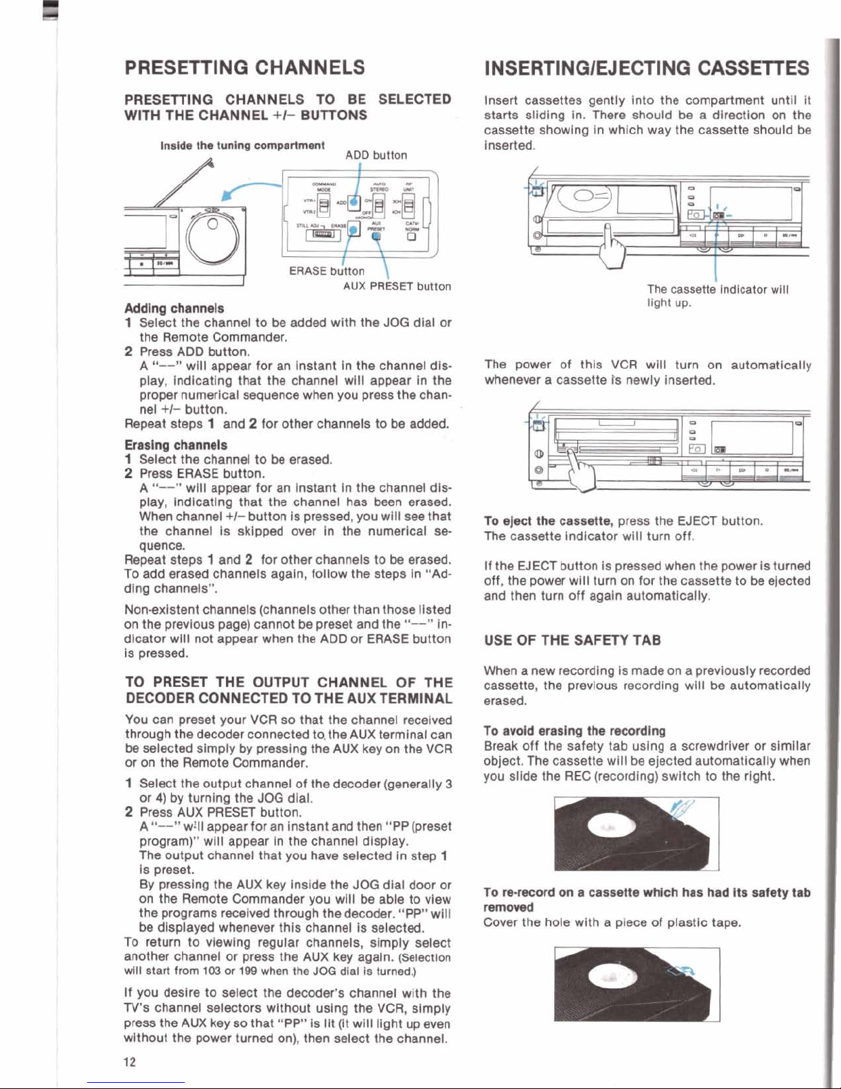
PRESETTING CHANNELS
PRESElllNG CHANNELS TO BE SELECTED
WITH THE CHANNEL
+I-
BUlTONS
Ineldo
tha
tunlng
wmpartmmt
ADD
button
ERASE
button
AUX
PRESET
button
Adding channela
1
Select the channel to be added wlth the
JOG
dlal or
the Remote Commander.
2
Press ADD button.
A
"--"
will appear for an Instant In the channel dls-
play, lndlcatlng that the channel wlll appear In the
proper numerical sequence when you press the channel
+I-
button.
Repeat steps
1
and 2 for other channels to be added.
Erasing
channels
1
Select the channel to
be
erased.
2
Press ERASE button.
A
"---
wlll appear for an Instant in the channel dl*
play, lndlcatlng that the channel has been erased.
When channel
+I-
button Is pressed, you wlll see that
the channel is
sklpped over In the
numerical
se.
quence.
Repeat steps
1
and 2 for other channels to
be
erased.
To add erased channels agaln, follow the steps
In "Ad-
ding channels".
Non-exlstent channels (channels other than those llsted
on the prevlous page) cannot
be
preset and the
"--"
Indlcator wlll not appear when the ADD or ERASE button
is pressed.
TO PRESET THE OUTPUT CHANNEL OF THE
DECODER CONNECTED TO THE
AUX
TERMINAL
You can preset your VCR so that the channel recelved
through the decoder connected to, the AUX terminal can
be
selected simply by presslng the AUX key on the VCR
or on the Remote Commander.
1
Select the output channel of the decoder (generally
3
or
4)
by turnlng the
JOG
dlal.
2
Press AUX PRESET button.
A
"--"
will amear for an lnstant and then "PP(~reset
program)" wili appear In the channel dlsplay.
''
The output channel that you have selected In step
1
Is preset.
By
presslng the AUX key Inside the
JOG
dlal door or
on the Remote Commander you wlll
be
able to vlew
the programs
recelved through thedecoder. "PP" will
be
displayed
whenever thls channel is selected.
To return to
vlewlng regular channels, simply select
another channel or press the AUX key agaln.
(Selection
wlll start from
103
or
199
when the
JOG
dlsl Is turned.)
Insert cassettes gently
Into the compartment until It
starts slldlng In. There should
be
a dlrectlon
on
the
cassette showlng in
which way the cassette should
be
Inserted.
The cassette
indlwtor
wlll
light up.
The power of
thls VCR wlll turn on automatlcally
whenever a cassette
is
newly inserted.
To
ejrct
the
cassette, press the EJECT button.
The cassette Indicator wlll turn off.
If
the EJECT button Is pressed when the power Is turned
off, the power wlll turn on for the cassette to
ba
ejected
and then turn off agaln automatlcally.
USE OF THE SAFETY TAB
When a new recordlng Is made on a prevlously recorded
cassette, the
prevlous recordlng wlll be automatlcally
erased.
To
avdd
mslng
Me
ncordlng
Break off the safety tab uslng a screwdriver or similar
object. me cassette
will be ejected automatically when
you slide the REC (recording)
swltch to the rlght.
TO
rrncord
on
a caueno wh~ch has had its safety tab
removed
Cover the hole wlth a piece of plastic tape.
If you deslre to select the decoder's channel wlth the
TV's channel selectors wlthout uslng the VCR, slmply
press the AUX key so that "PP" Is IIt (It will llght up even
wlthout the power turned on), then select the channel.
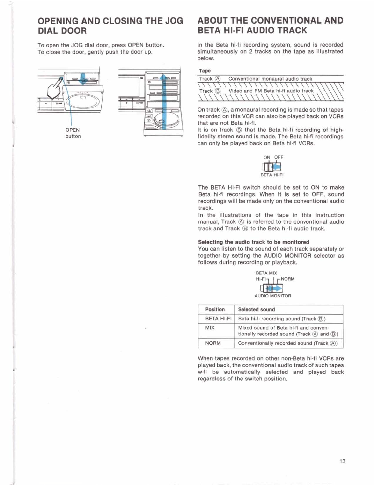
OPENING AND CLOSING THE JOG
ABOUT THE CONVENTIONAL AND
DIAL DOOR
BETA HI-FI AUDIO TRACK
To open the JOG dlal door, press
OPEN
button.
In the Beta
hl-fl recording system, sound Is recorded
To close the door, gently push the door up.
simultaneously
on 2 tracks on the tape as Illustrated
below.
Tap.
Track
@
Conventional monaural audlo track
.......................
Track
@I
Video and
FM
Beta hi-fi audio track
y
\\\\\\\\\\\\\\\\\\\\\\\\
On track @,a monaural recordlng Is made so that tapes
recorded on
this VCR can also be played back on VCRs
that are not Beta hl-fl.
It is on track
@
that the Beta hl-fl recording of hlgh-
button
fldellty stereo sound Is made. The Beta hl-fl recordings
can only
be
played back on Beta hl-fl VCRs.
iE
BETA
HI.FI
The BETA HI-FI swltch should
be
set to ON to make
Beta
hi-fl recordlngs. When
It
Is
set
to OFF, sound
recordings
wlll be made only on the conventional audio
track.
In the Illustrations of the tape in
this lnstructlon
manual, Track
@
Is referred to the conventional audlo
track and Track
@
to the Beta hi-fl audlo track.
Wectlng
the
audlo track
to
be
monitored
YOU can listen to the sound of each track separately or
together by settlng the AUDIO MONITOR selector as
follows durlng recordlng or playback.
BETA
MIX
"'
w
AUDIO
MONITOR
When tapes recorded on other non-Beta hl-fl VCRs are
played back, the conventlonal audio track of such tapes
wlll
be
automatically
selected and played back
regardless of the swltch
posltlon.
1
OPERATIONS
1
RECORDING
TV
PROGRAMS
Caution
Television
programs, films, video tapes and other materials may
be
copyrighted.
Unauthorized recording of such material
may be contrary to the provisions of the
-
copyright laws.
Also, use of this recorder with cable television transmission may require authorization
from the cable
televidon transmitter andlor program owner.
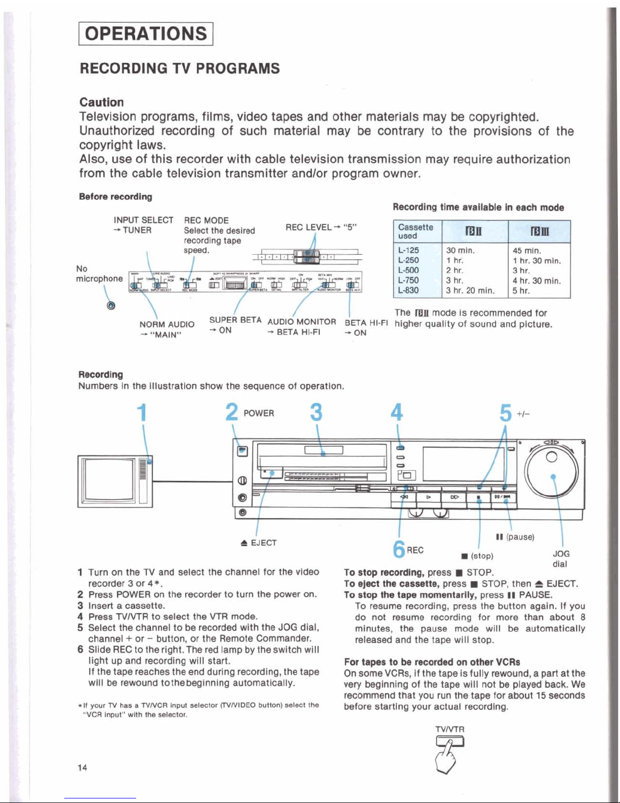
INPUT SELECT REC MODE
-TUNER Select
the
deslrad
REC LEVEL
-
"5"
~~~
~~
recording tape
\
NORM AUDIO
SUPE~~
BETA
AUDI~MONITOR
ETA
H
+
"MAIN"
-
ON -BETA HI-FI -ON
R.cordlng
Numbers In the lllustratlon show the sequence of operation.
L-125
45
mln.
1
hr. 30
rnln.
L-750
3
hr.
4
hr.
34
mln.
L830
3
hr.
20
mln.
'he
nlE
mode is recommended for
llgher quallty of sound and picture.
I
t
EJECT
1
Turn on the
TV
and select the channel for the video
recorder 3 or
4*.
2
Press POWER
on
the recorder to turn the power on.
3
Insert a cassette.
4
Press TVMR to select the VTR mode.
5
Select the channel to be recorded wlth the
JOG
dial,
channel
+
or - button, or the Remote Commander.
6
Sllde REC to the right. The
red
lamp by the swltch wlll
light up and recordlng wlll start.
If the tape reaches the end durlng recordlng, the tape
wlll
be
rewound tothebeglnnlng automatically.
*It
your
N
has a TVNCR
lnput selactw
(IVNlDEO
button)
aelect the
"VCR
Input" wlth the selector.
I
6
REC
(StOD)
I
JOG
-
. ..
dlal
To rtop ncordlng, press
STOP.
To eject the
cassette,
press
STOP,
then
C
WECT.
To stop the tape mommtarlly, press
II
PAUSE.
To resume recordlng, press the button again. If
you
do not resume recordlng for more than about
8
minutes, the pause mode wlll be automatlcally
released and the tape wlll stop.
For
1.p.l
to
be
recorded
on
other
VCRs
On
some VCRs. If the tape Is fully rewound, a part at the
very beginning of the tape wlll not
be
played back. We
recommend that you run the tape for about
15
seconds
before
startlng your actual recordlng.
TO VIEW ONE
TV
PROGRAM WHILE RECORDING
To
mwiva
and
record
SAP
(Second
Audlo
Program)
ANOTHER
brordcaats
Press the TVMR button
so
that the lamp of the button
turns off, then select the channel you want to view with
the channel selectors on the
N.*
.If
your
TV
ha8 a TVNCR
Input
selector,
simply
select
'7V"
wlth
the
aeleotor
and
then
choose
the
desired
channel.
TO START RECORDIN@
IN
THE MIDDLE OF A
RECORDED TAPE
1
Play back the recorded tape by pressing the W (play)
button.
2
At the point where you wish to start a new recordlng,
press
il
(pause) button.
3
Sllde the REC switch to the rlght.
The VCR will
be
in the recordlng pause mode and the
plcture selected by the INPUT SELECT switch (If it
Is
set to "TUNER", the
TV
program) wlll appear on the
monitor
screen.
4
Press I1 (pause) to release the pause mode.
Recording wlll begin.
The plcture may be a
little distorted in between the
recordings,
whlch Is due to the stopplng and starting of
the tape.
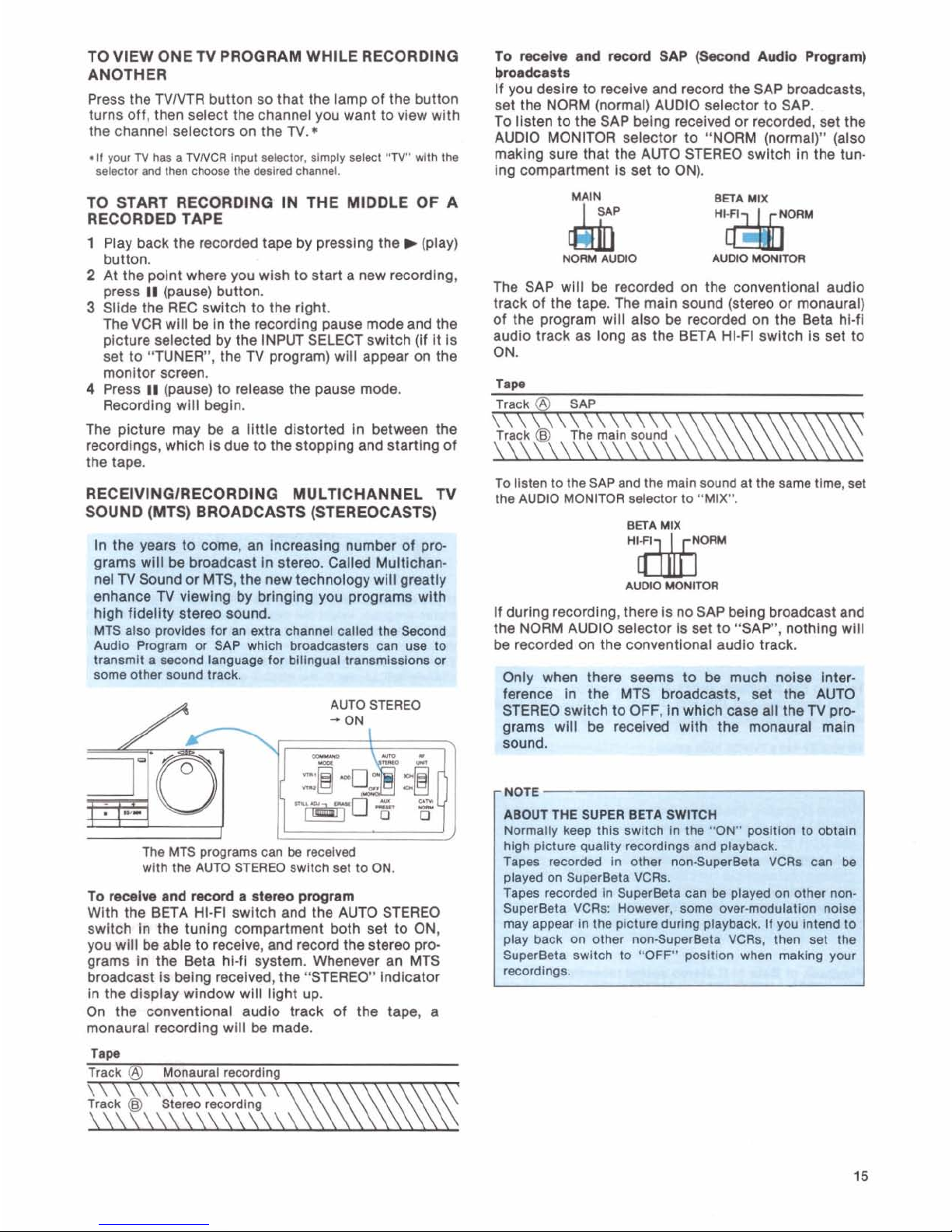
If you desire to receive and record the SAP broadcasts,
set the NORM (normal) AUDIO selector to SAP.
To
llsten to the SAP belng received or recorded, set the
AUDIO MONITOR selector to "NORM (normal)" (also
rnaklng sure that the AUTO STEREO swltch In the tuning compartment
Is set to ON).
MAIN
BETA
MIX
-
-
.
. . . . . ..
.
NORM
AUDlO
AUWO
"&iM
UONM
The SAP wlll be recorded on the conventlonal audio
track of the tape. The maln sound (stereo or monaural)
of the program wlll also be recorded on the Beta hi-fl
audio track as long as the BETA HI-FI swltch
is
set to
ON.
To
llsten to the
SAP
and the maln sound at the same tlme, set
RECElVlNQlRECORDlNQ MULTICHANNEL
TV
the
AUDIO
MONITOR
selector
to "MIX".
SOUND (MTS) BROADCASTS (STEREOCASTS)
BETA
MIX
-by
~7.Wr.j
In
the yea6 to
time,
an fii+6reaelng numbei
of
pprD:
glvlms wlll be broadcast in stereo. Called Multichsh.
Rel TV Sound or MTS, the new technology wlll grea*
:mhance TV viewlng by bringlng you programs wl*.
I&h fidelity stereo sound.
fHS
also provldes for an extra channel called the Seco~
Ndlo Prcgram or
SAP
which broadcasters can
uee
.,
&nsmit a second language for blllngual trenamlsslons or
me other sound track.
.
:y
..-
AUTO STEREO
-
ON
"&i
AUMO
MONITOR
If
durlng recordlng, there Is noSAP being broadcast and
the NORM AUDIO selector is set to "SAP.
nothlna will
-
be recorded on the conventlonal audlo track.
tWy
Wen there
suem
6%~
*:%-I
ference in the MTS broadcasts, set the AUTO
STEREO swltch to OFF, in which case all the
N
pre
]rams will be recelved with the monaural maln
The
MTS
programs can
be
recelved
wlth the
AUTO
STEREO swltch set to ON.
high
plciure quality recordlngs and ptaybaok.
Tapas recorded in other non4upweeta VCRs can be
played on SuperBeta VCRs.
To
mcelve and
ncord
a 8ter@0 program
I
Tapes recorded In SuperBeta can
be
played on other non-
Wlth the BETA HI-FI switch and the AUTO STEREO
SuperBeta VCRs:
Howsver,
some owr-modulation nolse
switch
In the tuning compartment both set to ON,
may appear
In the plcture durlng playback. If you Intend lo
you wlll
be
able to recelva, and record the stereo
pm
play back on other non4uperBeta VCRs, then set the
gram8 In the Beta hl-f1 system. Whenever an MTS
Superaeta swltch to "OFF" posltlon when making your
broadcast is belng
recelved, the "STEREO" indlcatcr
ecord
in the
dlsplay wfndow will llght up.
On the
conventional audlo track of the tape, a
monaural recording wlll be made.
Taw
Track
@
Monaural reoordlng
\\\\\\\\\\\\\\\
Track
@
Stereo recordlng
\\\\\\\\\\\\\\\\
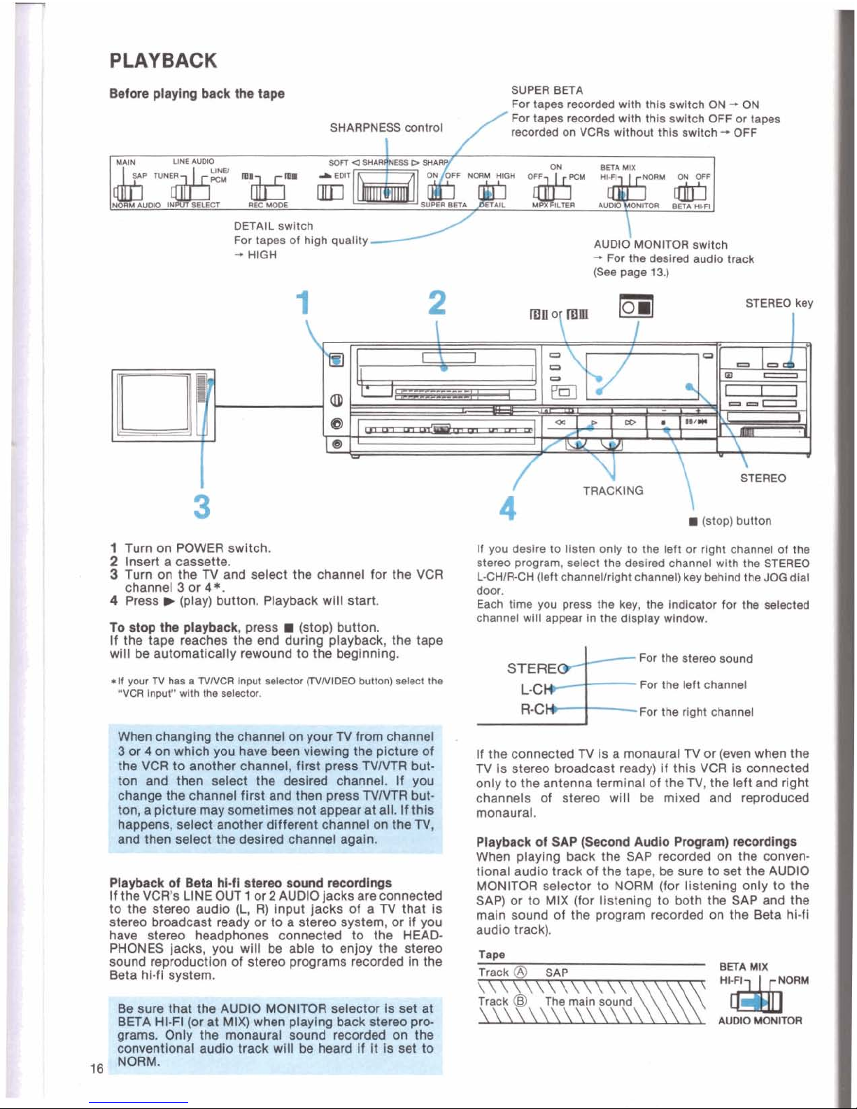
PLAYBACK
Before playing back
the
tap.
SUPER
BETA
For tapes recwded wlth this swltch ON
-
ON
For
tapes
mcmded wKh thle swltch OFF or tapes
SHARPNESS
control
recorded on VCRs without thls swltch
-.
OFF
I
DETAIL swltch
For tapes of high quality
AUDIO
MONITOR swltch
-
HIGH
+
For
tho
dealred sudlo track
(9ee
PW
13.)
STEREO key
I
STEREO
6
TRACKING
(stop) button
1
Turn on POWER
switch.
If
you deslre to llsten only to the left or rlght channel of the
2
Insert a cassette.
Stereo program, select the deslred channel with the STERK)
3
Turn on the
TV
and eslect the channel for the VCR
LCWRCH (left channellrlsht channel)
kev
behlnd theJOO dlsl
channel 3 or
4s.
4
Preas b (play) button. Playback wlll start.
-
door.
Each time
you
press
the key,
the
indloater
for
th. adected
channel wlll appear in ths dlsplay wlndow.
To
stop
tha
playback,
preas
(stop) button.
If the tape reaches the
end
durlng piam, the tape
will
be
automatically rewound to the beglnnlng.
For the stereo sound
*If
your
N
has a NNCR
lnpM
enledof
(WIVIDEO
button)
aalecl
lha
STERE
"VCR
input"
w~th
the
etw.
LC
For the left channel
RCW-F~~
the rlght channel
I
If the connected N is a monaural
TV
or (even when the
TV
is stereo broadcast ready) If thls VCR Is connected
only to the antenna
termlnal of them, the left and rlght
channels of stereo wlll be
mixed and reproduced
monaural.
flayback
of
SAP
(Second
Audio
Pmgmm)
mcodhp
When
Dlavlno back the SAP recorded on the conven-
tional audio
Gack of the tape,
be
sure to set the AUDIO
Playback
of
B.Ca
M-fl
atom0
wund
dn@s
MONITOR selector to NORM (for listening only to the
If
theVCR'sLINEOUT1 or2AUD'0jacksarec0nMed
SAP) or to MIX (for llstenlng to both the SAP and the
the
stereo
(1
R)
Input jacks
Of
a
TV
that
Is
main
sound of the program recorded on the
&ta
hi-fi
stereo broadcast ready or to a stereo system, or If you
have
starm haadnhonaa connectad tn the
HEAD-
track).
.
.
- . -
-. - .
- -
.
.
-
--
r..
-
.
.
-
-
-
-
.
. . .
- - - - - - - -
.
. - .
. - .
-
PHONES jacks, you wlll
be
able to enjoy the stereo
sound
reproduction
of stereo programs recorded in the
Track
@
SAP
BElA
MlX
Beta hi-f1 system.
....................
~1Ir-
-
BETA HI-FI tor at MIX) when playing back stereo pr
grams. Only the monaural sorind-recorded on ti
conventional
audlo track will be heard If
It
is set to
16
NORM.
 Loading...