

Page 1
SALES NETWORK
•
SAMSUNG TECHWIN CO., LTD.
145-3, Sangdaewon 1-dong, Jungwon-gu, Seongnam-si,
Gyeonggi-do 462-703, Korea
TEL : +82-31-740-8137~8141 FAX : +82-31-740-8145
•
SAMSUNG OPTO-ELECTRONICS AMERICA,INC.
ELECTRONIC IMAGING DIV.
40 Seaview Drive, Secaucus, NJ 07094, U.S.A
TEL : +1-201-902-0347 FAX : +1-201-902-0429
•
SAMSUNG TECHWIN MOSCOW OFFICE
Korp 14, 37-A, PR-KT, Lenningradsky, Moscow 125167, Russia
TEL : +7-95-258-9296,9298 FAX : +7-95-258-9297
www.samsungtechwin.com
www.samsungcctv.com
•
SAMSUNG OPTO-ELECTRONICS UK, LTD.
Samsung House, 1000 Hillswood Drive, Hillswood Business
Park Chertsey, Surrey KT16 OPS
TEL : +44-1932-45-5308 FAX : +44-1932-45-5325
•
TIANJIN SAMSUNG OPTO-ELECTRONICS CO., LTD.
7 Pingchang Rd, Nankai Dist. Tianjin 300190, P.R China
TEL : +86-22-2761-4724(33821) FAX : +86-22-2761-6514
P/No. : Z6806-0682-01A
VAN 05. 10
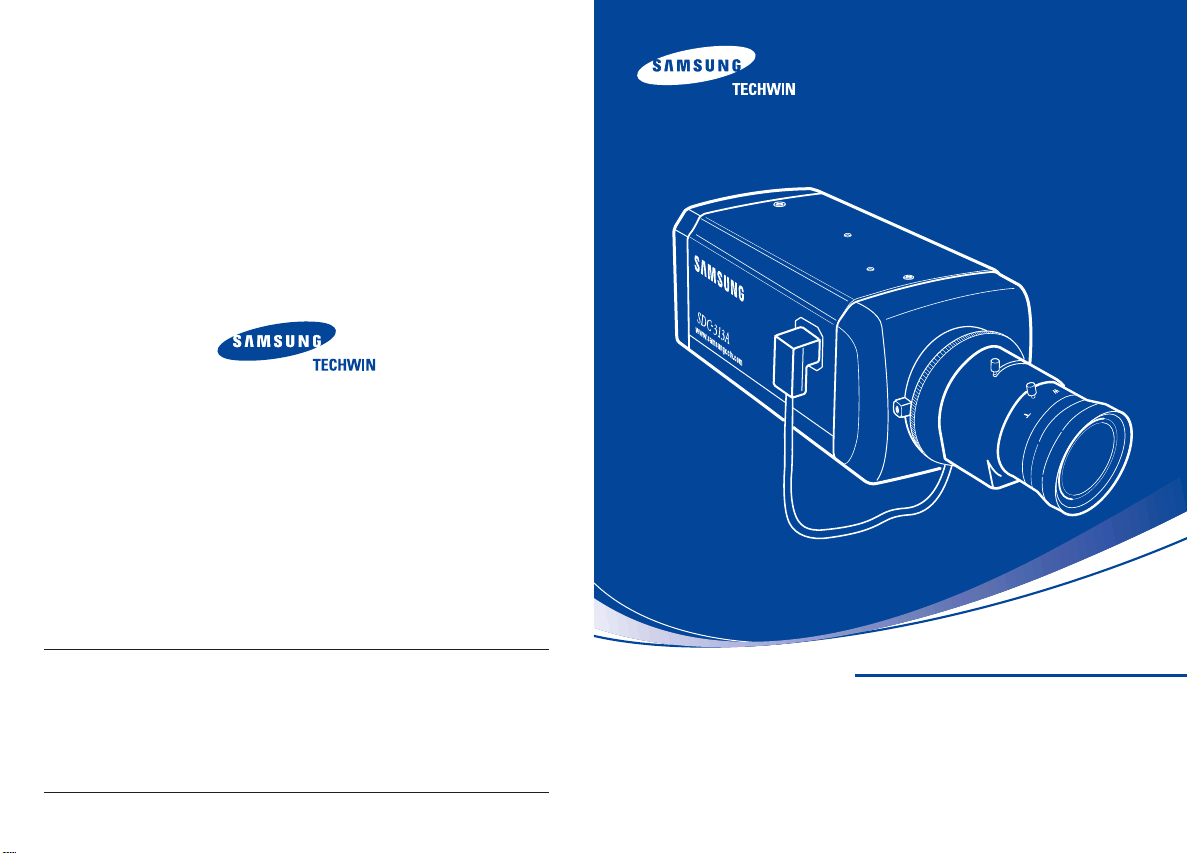
HIGH RESOLUTION COLOR CAMERA
INSTRUCTION MANUAL
SDC-313A SERIES
About this manual
Before installing and using the camera, please read this manual carefully. Be sure to keep it handy for later reference.
Page 2
Thank you for purchasing a SAMSUNG CCD CAMERA.
Before operating the camera, confirm the camera model and proper input
power voltage. In order to that you can understand this manual thoroughly,
we'll introduce our model description.
■ SDC-313A SERIES
• NTSC MODELS •PAL MODELS
SDC-313AND SDC-313APD
SDC-313ANA SDC-313APA
■ MODEL DESCRIPTION
• SDC-313AXX
___
POWER SOURCE
SIGNAL SYSTEM
EXPORT MODEL
• SIGNAL SYSTEM
N --> NTSC MODEL
P --> PAL MODEL
• POWER SOURCE
D --> DC 12V
A --> AC 24V~
Correct Disposal of This Product
(Applicable in the European Union and other European countries with separate collection systems)
This marking shown on the product or its literature, indicates that it should not be disposed with other
household wastes at the end of its working life. To prevent possible harm to the environment or human
health from uncontrolled waste disposal, please separate this from other types of wastes and recycle it
responsibly to promote the sustainable reuse of material resources.
Household users should contact either the retailer where they purchased this product, or their local
government office, for details of where and how they can take this item for environmentally safe recycling.
Business users should contact their supplier and check the terms and conditions of the purchase contract.
This product should not be mixed with other commercial wastes for disposal.
(Waste Electrical & Electronic Equipment)
The lightning flash with an arrowhead symbol, within an equilateral triangle is
intended to alert the user to the presence of uninsulated “dangerous voltage”
within the product's enclosure that may be of sufficient magnitude to
constitute a risk of electric shock to persons.
The exclamation point within an equilateral triangle is intended to alert the user
to the presence of important operating and maintenance (servicing)
instructions in the literature accompanying the appliance.
INFORMATION-This equipment has been tested and found to comply with limits
for a Class A digital device, pursuant to part 15 of the FCC Rules. These limits are
designed to provide reasonable protection against harmful interference when the
equipment is operated in a commercial environment. This equipment generates,
uses, and can radiate radio frequency energy and, if not installed and used in
accordance with the instruction manual, may cause harmful interference to radio
communications.
Operation of this equipment in a residential area is likely to cause harmful
interference in which case the user will be required to correct the interference at
his own expense.
WARNING -Changes or modifications not expressly approved by the manufacturer
could void the user’s authority to operate the equipment.
WARNING : To prevent electric shock and risk of fire hazards:
Do NOT use power sources other than that specified.
Do NOT expose this appliance to rain or moisture.
This installation should be made by a qualified service person and
should conform to all local codes.
Page 3
Contents
Precautions
Composition
Name and Function of Each Section
FRONT
SIDE
BOTTOM
BACK
Installation
Lens
Connecting to a monitor
Connecting to power
8
10
11
11
12
13
14
15
15
18
19
Camera Operation
Menu
Settings
• LENS (selection)
• SHUTTER (condition and speed control)
• WHITE BALANCE control
• BACKLIGHT (Backlight Compensation)
• AGC (Auto Gain Control)
• SSNR (Samsung Super Noise reduction)
• SENS-UP (Low illuminance)
• SPECIAL
• EXIT
Troubleshooting
Specification
20
20
21
23
24
25
26
27
28
29
30
35
36
38
COLOR CCD CAMERACOLOR CCD CAMERA User’s ManualUser’s Manual
54
Page 4
Features
Warning
Horizontal Resolution 530 TV Lines
Clear image quality has been achieved by employing a CCD with 410,000 pixels(NTSC), 470,000
pixels (PAL), which provides a horizontal resolution of 530 TV lines.
Electronic IRIS
The electronic IRIS function enables continuous automatic control of the shutter between 1/60(1/50) ~
1/120,000 seconds.
PRIVACY Function
The PRIVACY function conceals the areas you do not wish to appear on the screen.
VIDEO/DC Drive Lens
The video drive lens and the DC drive lens can be selected by the touch of a switch.
High Sensitivity
The built-in high sensitivity COLOR CCD enables a clear image even in 0.002 Lux(Sens-Up) illumination.
SSNR (Samsung Super Noise Reduction)
By using built-in SSNR function manufactured by SAMSUNG TECHWIN, the amount of low
illuminance noise has been significantly reduced, and the signal-to-noise ratio(S/N) as well as
horizontal resolution have been improved, resulting in a clear and sharp image display even in the dark.
Controlled by OSD Menu
The camera can be controlled by selecting text displayed on the monitor screen.
Additional Functions
SENS-UP, MOTION DETECTION, MIRROR, SHARPNESS and SYNC(INT/LL) functions are also available.
The camera needs periodic inspection.
Contact an authorized technician for inspection.
Stop using your camera when you find a malfunction.
If you use your camera around smoke or unusual heat for a long time, a fire
may be caused.
Do not Install the camera on a surface that can not support it.
Unless the surface is suitable, it could cause falling or other hazards.
Do not handle the camera with wet hands
It could cause an electric shock.
Do not disassemble the camera.
It may result in fire, electric shock or other hazards.
Do not use the camera close to a gas or oil leak.
It may result in fire or other hazards.
COLOR CCD CAMERA User’s Manual
6
COLOR CCD CAMERA User’s Manual
7
Page 5
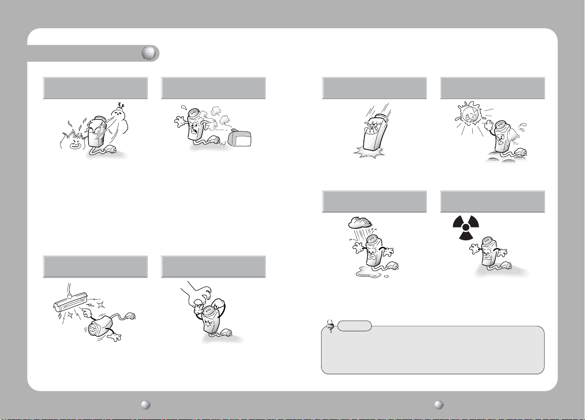
Precautions
Do not install under extreme
temperature conditions.
Use only under temperature conditions
between -10˚C and +50˚C. Provide good
ventilation when using in high temperature
conditions.
Do not install under unstable
lighting conditions.
Severe lighting changes or flickering may
hinder normal camera operation.
Do not install in high humidity
environment.
May lower image quality.
Avoid touching the camera lens.
The lens is the most important component
of the camera. Be careful not to smear it
with fingerprints.
Do not drop the camera or
subject it to physical shock.
May cause a product malfunction.
Do not expose the camera to
rain or other types of liquids.
Wipe dry any liquids. Liquids may contain
minerals that are corrosive to electronic
Never keep the camera face to
strong light directly.
May damage the CCD.
Do not expose the camera to
radioactivity.
Radioactivity exposure may damage the
CCD.
components.
Notes
• Exposure to a spotlight or an object emitting strong light may cause smear or
blooming.
• Ensure that the power source complies with normal specifications before supplying
it to the camera.
COLOR CCD CAMERACOLOR CCD CAMERA User’s ManualUser’s Manual
98
Page 6
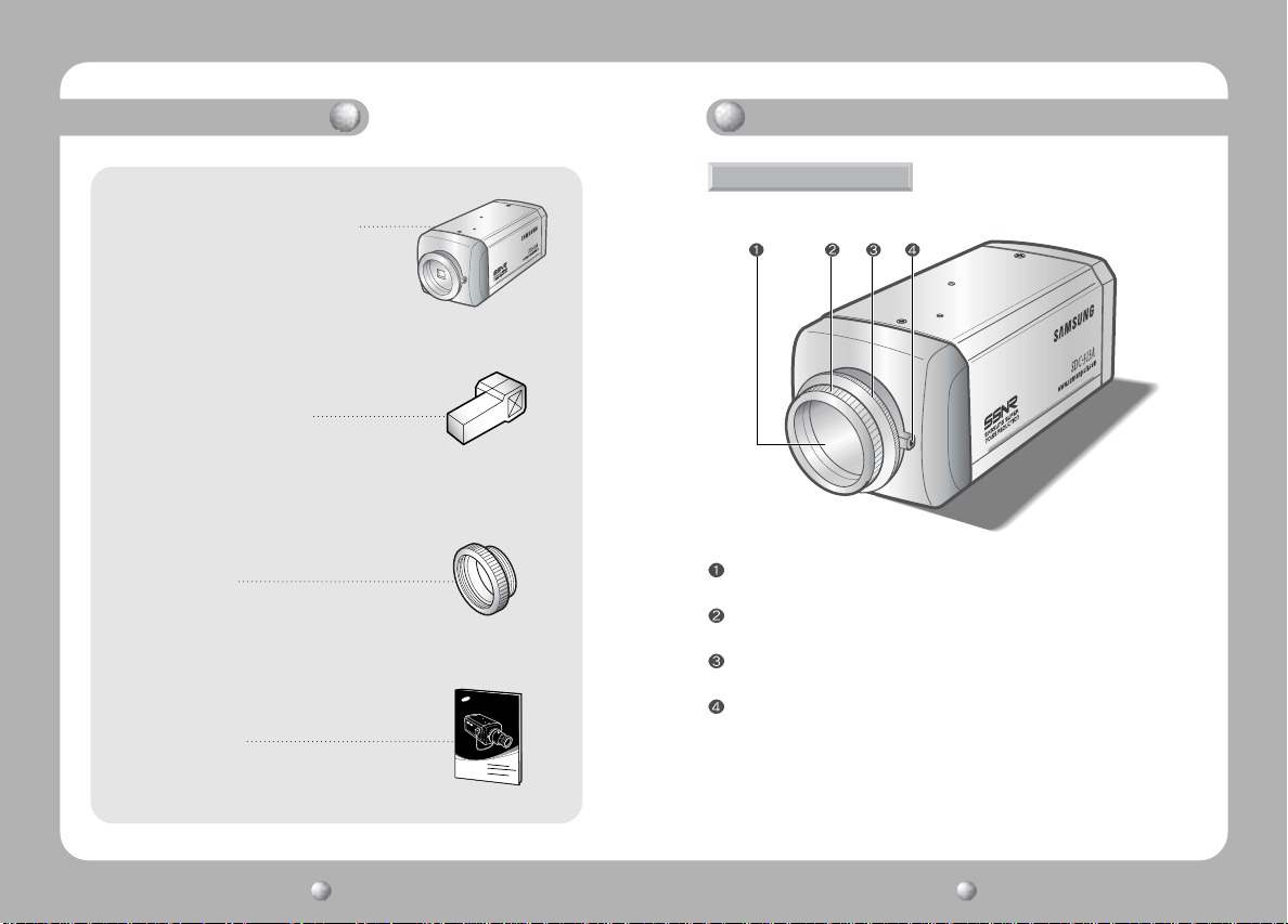
Component
1. HIGH RESOLUTION COLOR CAMERA
2. Auto iris lens connection plug
Names and Functions of Parts
FRONT
3. C-Mount adaptor
4. Instruction manual
CCD protection cap
Please cover the CCD SENSOR when not using it.
C-Mount lens adaptor
Please attach the C-Mount lens here.
CS-Mount lens adaptor
Please remove the C-MOUNT lens adaptor and then attach it.
Back Focus clamp screw
Please loosen the clamp screw with a screwdriver before adjusting the Back Focal
length.
COLOR CCD CAMERACOLOR CCD CAMERA User’s ManualUser’s Manual
1110
Page 7
Names and Functions of Parts
L
SIDE BOTTOM
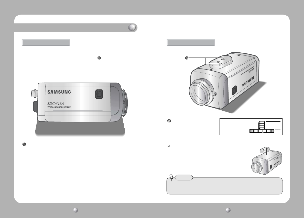
Auto iris lens connector
This is the connection terminal for the auto iris lens.
Mounting bracket screw hole
Please use the screw hole when
fixing the camera onto the
mounting bracket. Please use
1/4"-20 UNC (20 THREAD)
L:4.5mm±0.2mm (ISO standard),
or 0.197" (ASA standard)
the clamp screw as specified below.
The mounting bracket can be separated and attached to the top of the
camera.
In this instance please do not tighten the screw to a depth of
more than 4mm, otherwiseserious damage can occur to the
inside of the camera.
Notes
• This camera package does not include the mounting bracket. Please refer to the
user's manual for installation of the mounting bracket.
COLOR CCD CAMERACOLOR CCD CAMERA User’s ManualUser’s Manual
1312
Page 8
Names and Functions of Parts
Installation
BACK
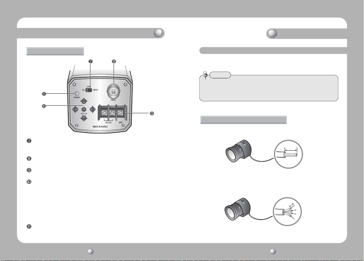
Auto iris lens selection switch
Please change the mode to DC or VIDEO depending on the type of auto iris
lens being used.
Video output terminal
Sends video signal and connects to the video input terminal of the monitor.
Power input terminal
Connects to the power appropriate to each model.
Setting button
•SETUP button : Used for the menu display. This button can be used to confirm
settings after changing the value of the selected function or
current conditions.
•UP & DOWN buttons : Used for selecting items by moving the cursor up or
down on the menu screen.
•LEFT & RIGHT buttons : Used when changing item values, by moving the cursor
to the left or right on the menu screen.
Power lamp
Lights up when the correct power is supplied to the camera.
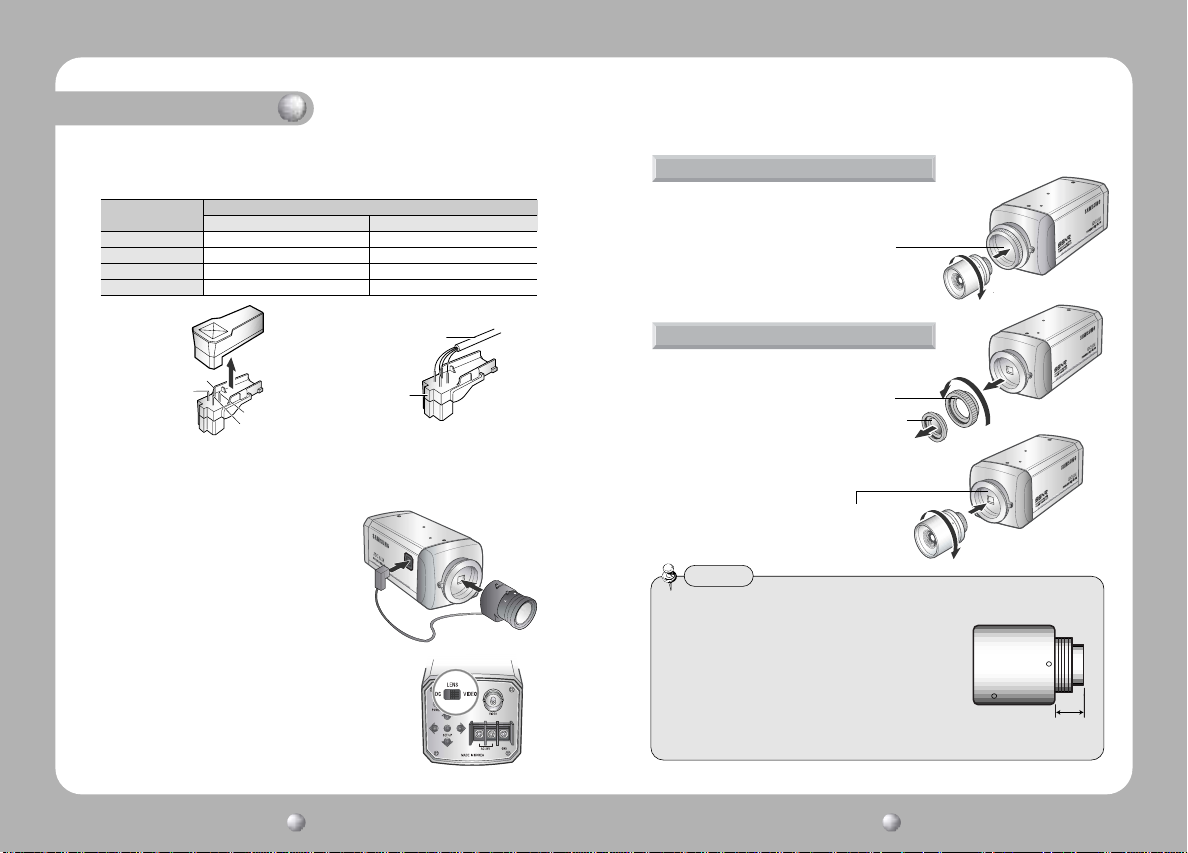
Lens
Lenses are sold separately. Lenses such as an auto iris lens, CS-Mount lens and
C-Mount lens can be used.
Notes
• Please keep the lens clean.
• Any foreign objects and fingermarks on the lens can cause inferior image quality
in low light level conditions.
When using an auto iris lens
1. Please peel off about 8mm of the outer skin of the auto iris lens cable.
approx. 8mm
2. Please peel off about 2mm of the outer skin of the insulated conductor inside
the lens cable.
approx. 2mm
COLOR CCD CAMERA User’s Manual
14
COLOR CCD CAMERA User’s Manual
15
Page 9
Installation
3. Please remove the cover of the auto iris lens connection plug and solder the
lens cable to the connector pin in the plug.
Pin No.
No.1 Pin Damping- Red (power)
No.2 Pin Damping+ NC
No.3 Pin Drive+ White (video signal)
No.4 Pin Drive- Black (GND)
No.3 Pin
No.1 Pin
DC VEDIO
No.4 Pin
No.2 Pin
LENS
Lens cable
Connector
4. Please replace the auto iris lens connection plug cover and take off the CCD
protection cap, and then attach the auto iris lens to the camera by screwing
it in clockwise.
5. Please insert the connection plug that is
connected to the auto iris lens cable into
the auto lens connector, which is located on
the side of the camera.
6. Please set the lens selection switch, located on the
side of the camera, to DC or VIDEO depending on the
type of auto iris lens which is being used.
When using a C-Mount lens
Please take off the CCD protection cap and attach the
C-Mount lens to the camera by screwing it in clockwise.
C-mount adaptor
When using a CS-Mount lens
1. Please take off the CCD protection cap and
C-mount adaptor.
2. Please attach the CS-Mount lens to the camera by
screwing it in clockwise.
Notes
•
Please use the specified lens connection parts as shown in the picture below.
The use of the wrong sized parts of the wrong size may cause
damage to the inside of the camera or result in poor fitting.
• Use of a lens which is too heavy affects the balance of the
camera and may cause a malfunction. Please use a lens
that weighs less than 450g.
• Please select Av mode if possible when adjusting the
automatic light control (ALC) of an auto lens. Use of PK
mode may cause hunting.
C-mount adaptor
CCD protection cap
C-mount adaptor
C-mount lens : 10 mm or less
CS-mount lens : 5 mm or less
COLOR CCD CAMERA User’s Manual
16
COLOR CCD CAMERA User’s Manual
17
Page 10
Installation
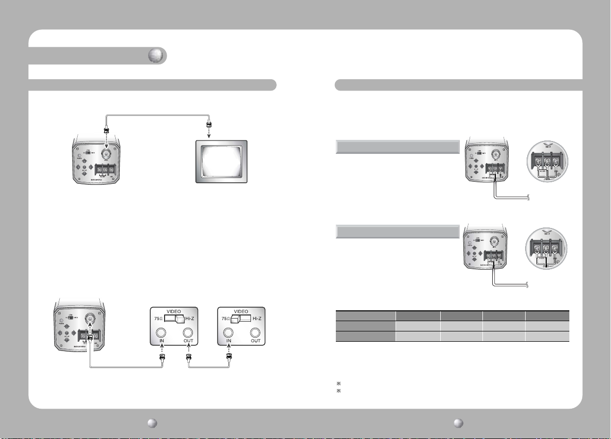
Connecting to a Monitor
Please connect the video output terminal located on the back of the camera to the
monitor.
CCD Camera
• The connection method varies depending on the type of monitor and accessories.
Please refer to the user's manual for each instrument.
• Please turn off the power when connecting.
• Please select Hi-Z on the 75Ω/Hi-Z switch for the intermediate video TV set and
select 75Ω for the Intermediate device as shown in the picture below.
CCD Camera
Intermediate End monitor
Monitor
Connecting to Power
Each model has a different power input specification.
Please check the model type and standard power requirement before connecting
to power.
AC Power Type (AC 24V, 300mA)
Use AC24V, 300mA adaptor.
For SDC-313ANA/SDC-313APA.
DC Power Type (DC 12V, 500mA)
Use DC12V, 500mA adaptor.
For SDC-313AND/SDC-313APD.
When the resistance value of copper wire is at [20°C(68°F)]
Copper wire size(AWG) #24(0.22mm2) #22(0.33mm2) #20(0.52mm2) #18(0.83mm2)
Resistance value(Ω/m) 0.078 0.050 0.030 0.018
Voltage drop(V/m) 0.028 0.018 0.011 0.006
• As shown in the table above, voltage decreases as the wire gets longer.
Therefore use of an excessively long adaptor output line for connection to the
camera may affect the performance of the camera.
Standard voltage for camera operation : DC 12V±10%
There may be some deviation in voltage drop depending on the type of wire and the manufacturer.
COLOR CCD CAMERACOLOR CCD CAMERA User’s ManualUser’s Manual
1918
Page 11
Camera Operation
Camera Operation
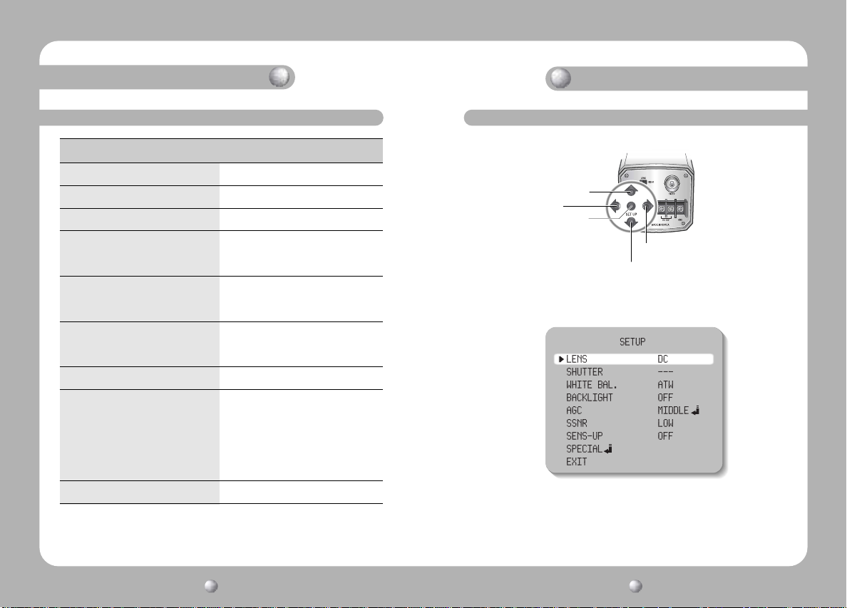
Menu
SETUP menu
LENS (selection) · MANUAL · DC/VIDEO
SHUTTER (Conditon and speed control) · ESC · MANUAL · FLK
WHITE BALANCE control · ATW · AWC · MANUAL
BACKLIGHT
(Backlight compensation)
AGC (Auto Gain Control) · OFF · LOW · MIDDLE
SSNR
(Samsung super noise reduction)
SENS-UP (Low illuminance) · OFF · AUTO
SPECIAL · CAMERA ID · SYNC
EXIT
· OFF · LOW · MIDDLE
· HIGH
· HIGH
· OFF · LOW · MIDDLE
· HIGH
· MOTION DET · PRIVACY
· MIRROR · SHARPNESS
· RESET · RETURN
Settings
Settings can be made using the 5 buttons located on the back of the camera.
UP button
LEFT button
SETUP button
RIGHT button
DOWN button
1. Please press the SETUP button
• Settings can now be made. The SETUP menu is displayed on the monitor.
2. Please select any function you wish to activate by using the UP and DOWN
buttons.
• The arrow can be moved up or down by using the UP and DOWN buttons.
Please position the arrow to point to the function you wish to operate.
COLOR CCD CAMERA User’s Manual
20
COLOR CCD CAMERA User’s Manual
21
Page 12
Camera Operation
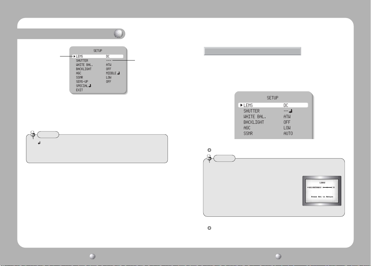
Select any function you
wish to operate by
using the UP and
DOWN buttons.
Modes can be changed
using the LEFT and
RIGHT buttons.
3. Please press the LEFT or RIGHT button if you wish to change mode.
• When the LEFT or RIGHT button is pressed, available values and modes are
displayed in order. Please keep pressing the button until you get to the mode
you wish to operate.
4. Please select 'EXIT' and then press the SETUP button to finish the setting.
Notes
• If appears at the mode you wish to operate, it means that there is a submenu which can be selected by pressing the SETUP button.
• If---appears at the mode item, it means that there is no mode available to be
selected.
LENS (selection)
This function is used to adjust the brightness of the screen.
1. When the SETUP menu is displayed on the screen, please position the arrow
to point to 'LENS' by using the UP and DOWN buttons.
2. Please select the type of the lens you wish to use by pressing the LEFT or
RIGHT button.
DC/VIDEO: Auto iris lens selection
Notes
• When using an auto iris lens, the setting of the auto iris lens selection switch,
located on the back of the camera, must be on DC or
VIDEO depending on the type of the lens which is
being used. (Please refer to the picture on page 15)
• The brightness of the screen can be adjusted in DC
mode. The brightness can be adjusted within the
range of 1 ~ 70. The optimum level of brightness for
the user can be achieved by adjustment.
MANUAL: Manual lens selection
3. Please press the SETUP button if you wish to return to the previous menu.
COLOR CCD CAMERACOLOR CCD CAMERA User’s ManualUser’s Manual
2322
Page 13
Camera Operation
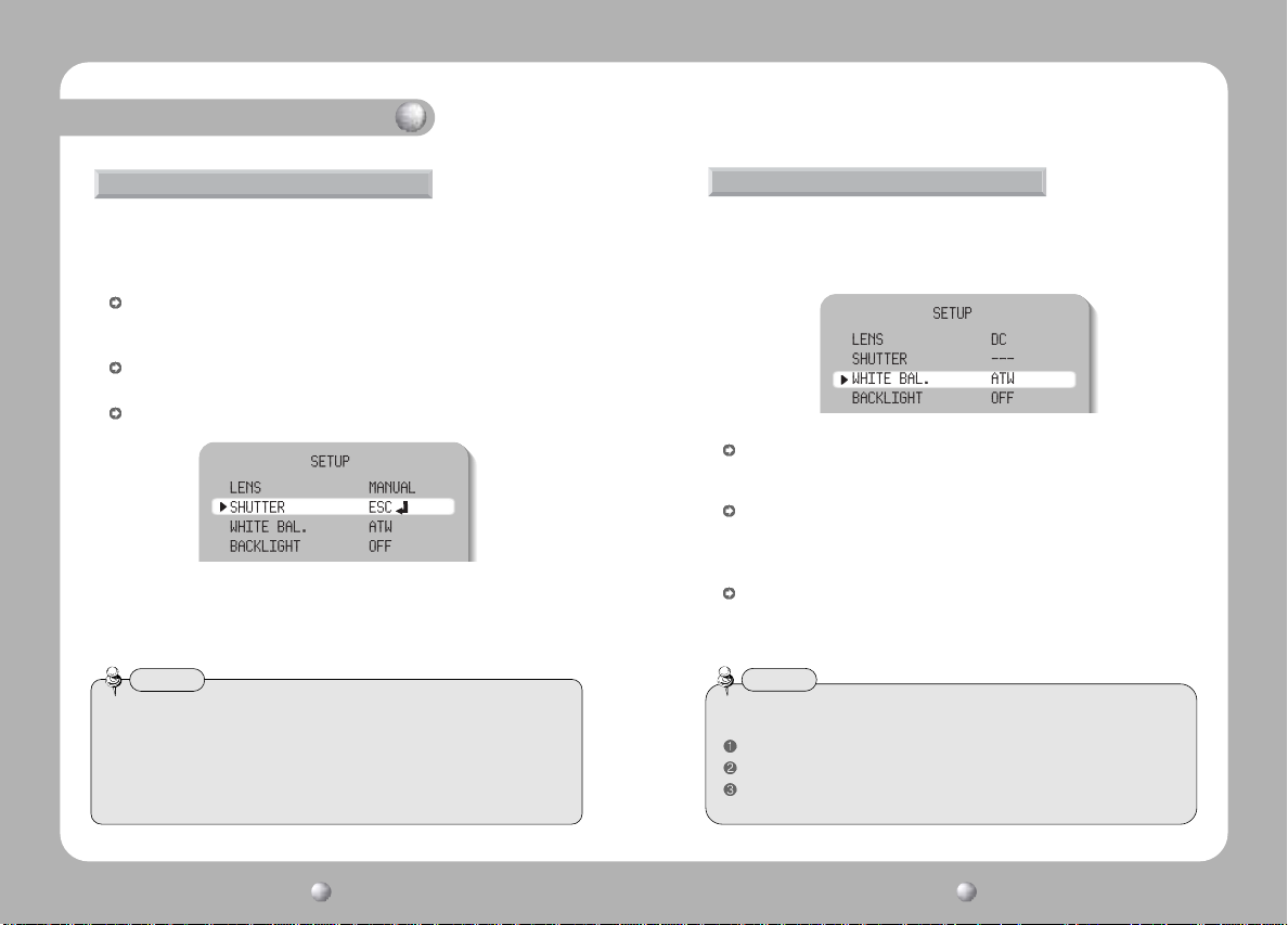
SHUTTER (condition and speed control)
Because of using the DC lens, the shutter speed is fixed at 1/60.
1. When the SETUP menu is on the screen, please position the arrow to point
to 'SHUTTER' by using the DOWN button.
2. Please select the shutter mode by pressing the LEFT or RIGHT button.
FLK: Please select 'FLK' mode when flickering occurs on the screen, due to an
imbalance between illumination and frequency. NTSC Model:1/100, PAL
MODEL: 1/120
ESC: Auto control of the shutter speed can be achieved. When ESC mode is on, the
speed is controlled automatically according to the brightness of the screen.
MANUAL:The shutter speed can be controlled manually.
3. Please select 'MANUAL' mode if you wish to adjust the shutter manually.
• You can select speed from ‘1/60’ to ‘1/120,000’sec (NTSC Models), ‘1/50’
to ‘1/120,000’sec (PAL Models).
4. Please press the SETUP button when all the settings are complete.
Notes
• When selecting DC/VIDEO lens, the shutter speed is fixed at 1/60 (1/50).
• While using the internal synchronous system, if the shutter setting is on
'ESC' and the camera is directly facing a bright fluorescent light, the image on
the screen can be adversely affected. Therefore please choose the installation
location with care.
• When 'MANUAL' mode is on, the SENS UP function does not operate.
WHITE BALANCE control
The screen color can be adjusted by using the WHITE BALANCE function.
1. Please position the arrow to point to 'WHITE BAL' on the SETUP menu by
using the UP and DOWN buttons.
2. Please select the mode you wish to operate by pressing the LEFT or RIGHT button.
*Please select one of the 3 modes below.
ATW(Auto Tracking White Balance): This mode can be used within the color
temperature range 1,800°K ~ 10,500°K (Ex. fluorescent light, outdoor, sodium
vapor lamp or inside tunnels)
AWC(Auto White Balance Control): Please press the SETUP button while the
camera is directed at a piece of white paper to obtain the optimum state under
current illumination. If the environment including the light source is changed, you
have to adjust the white balance again.
MANUAL: The manual adjustment mode enables finer adjustment. Please select
ATW or AWC first. Please change to manual adjustment mode and press the SETUP
button. Please set the appropriate color temperature, and then increase or decrease
the red and blue color values while monitoring the color changes on the object.
Notes
•Under the following conditions the WHITE BALANCE function may not operate
properly. In such cases, please select the AWC mode.
When the object’s surroundings have a very high color temperature (Ex. a clear sky and sunset)
When the object’s surroundings are dark
If the camera directly faces a fluorescent light or is installed in a place where there are
considerable changes in illumination, the WHITE BALANCE function may become unstable.
COLOR CCD CAMERACOLOR CCD CAMERA User’s ManualUser’s Manual
2524
Page 14
Camera Operation
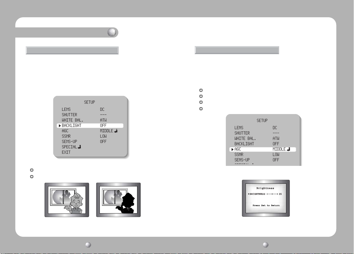
BACKLIGHT (Backlight Compensation)
When there is a strong backlight behind the object, clear images of the background
as well as the object can still be obtained by using the BACKLIGHT function.
1. Please position the arrow to point to 'BACKLIGHT' on the SETUP menu by
using the UP and DOWN buttons.
2. Please select the mode you wish to operate by pressing the LEFT or RIGHT
button.
HIGH/MIDDLE/LOW: You can adjust the sensitivity of Backlight Compensation.
OFF: BACKLIGHT function does not operate.
BACKLIGHT ON BACKLIGHT OFF
AGC (Auto Gain Control)
1. Please position the arrow to point to 'AGC' on the SETUP menu by using the
UP and DOWN buttons.
2. Please select the mode you wish to operate by pressing the LEFT or RIGHT
button. As the level of gain increases, the screen gets brighter and the level
of noise also increases.
HIGH: The gain increases or decreases within the range of 6dB ~ 34dB.
MIDDLE: The gain increases or decreases within the range of 6dB ~ 30dB.
LOW: The gain increases or decreases within the range of 6dB ~ 18dB.
OFF: The gain is fixed at 6dB.
3. Please press the SETUP button. The BRIGHTNESS can be adjusted within the
range of 1~70.
4. Please press the SETUP button when all the settings are complete.
COLOR CCD CAMERA User’s Manual
26
COLOR CCD CAMERA User’s Manual
27
Page 15
Camera Operation
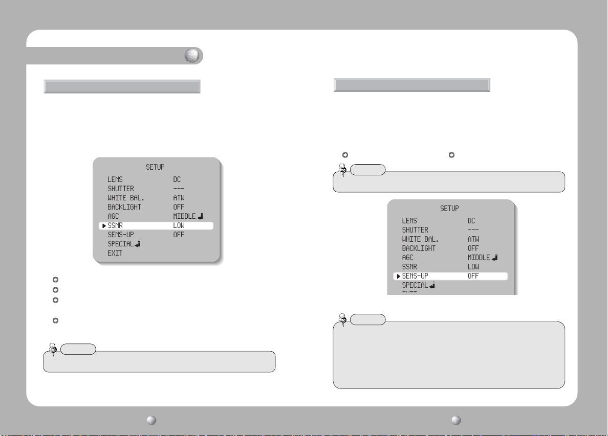
SSNR (Samsung Super Noise reduction)
The background noise in the low light level decreases automatically as the level
of gain changes.
1. Please position the arrow to point to 'SSNR' on the SETUP menu by using the
UP and DOWN buttons.
2. Please select the mode you wish to operate by pressing the LEFT or RIGHT button.
OFF: There is no reduction in noise level.
LOW: There is a small reduction in noise level with almost no ghost image.
MIDDLE: The most effective mode. There is a sufficient reduction in noise levels
without causing much ghost imaging.
HIGH: The level of noise is reduced greatly, however there is an increase in ghost
imaging.
Notes
• When AGC is turned off, SSNR does not operate.
SENS-UP (Low illuminance)
SENS-UP helps maintain a bright, clear screen image by automatically detecting
changes in the level of light in low light level conditions.
1. Please position the arrow to point to 'SENS-UP' on the SETUP menu by
using the UP and DOWN buttons.
2. Please select the mode you wish to operate by pressing the LEFT or RIGHT button.
AUTO: Low light level auto mode OFF: The function does not operate.
Notes
• When SHUTTER is in the manual mode, SENS-UP does not operate.
3. Please press the SETUP button when all the settings are complete.
Notes
•The maximum storage magnification in low light level can be adjusted by pressing
the SETUP button in 'AUTO' mode.(X2~X128)
•As the magnification increases, the screen gets brighter; moving object gets more
afterimage.
•If storage magnification is increased while SENS UP is operating, it may cause noise,
and spots may appear; however this is normal.
COLOR CCD CAMERA User’s Manual
28
COLOR CCD CAMERA User’s Manual
29
Page 16
Camera Operation
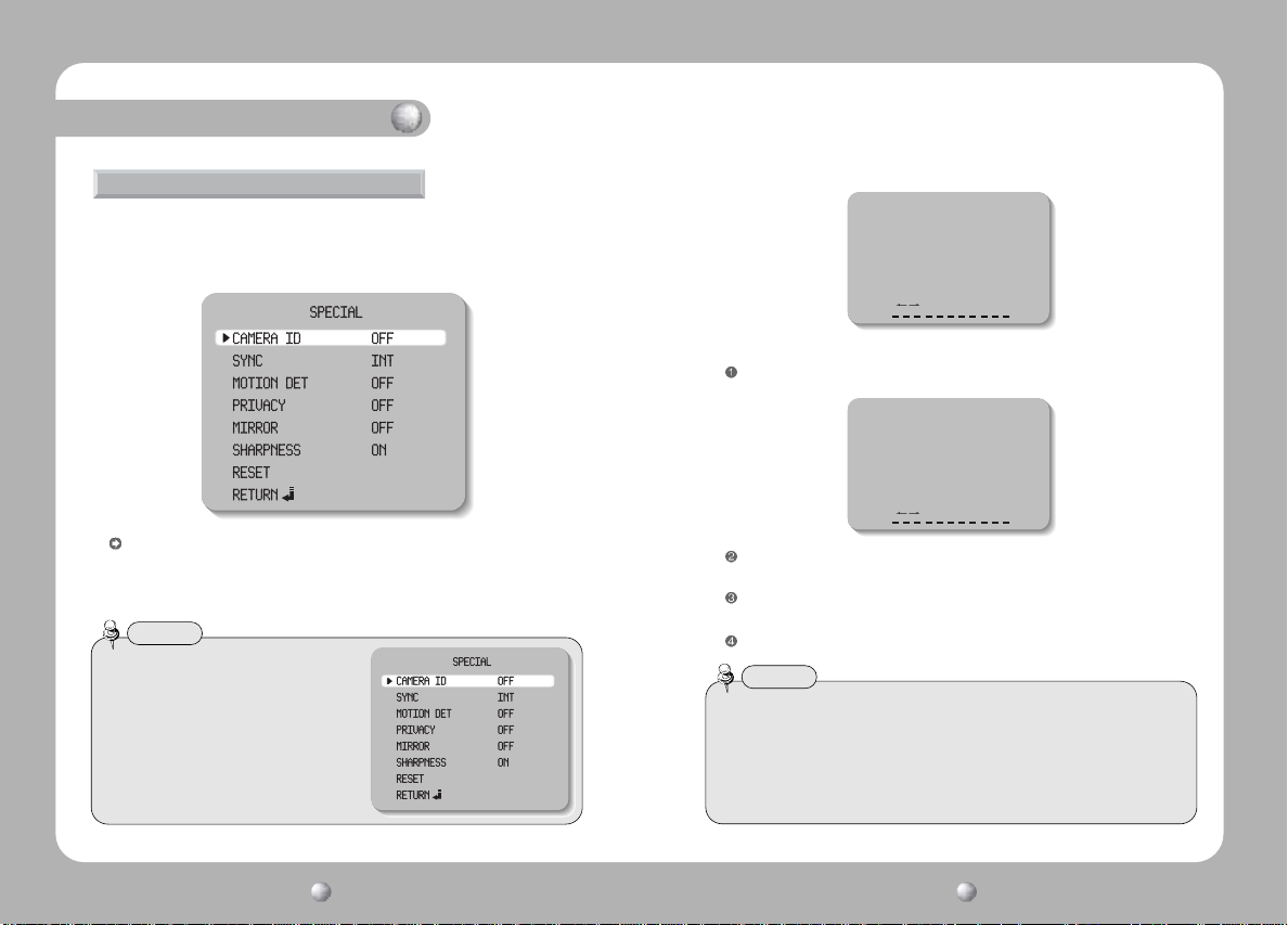
SPECIAL
1. Please position the arrow to point to 'SPECIAL' on the SETUP menu by using
the UP and DOWN buttons.
2. Please select the mode you wish to operate by pressing the UP or DOWN
button.
CAMERA ID: If the ID is input, the camera ID appears on the monitor.
1) Please position the arrow to point to 'CAMERA ID' by using the UP or DOWN
button.
2) Please select 'ON' by pressing the LEFT or RIGHT button.
Notes
• If 'OFF' is selected, the ID does not appear
on the monitor even if it has been input.
3) Please press the SETUP button.
Camera ID
ABCDEFGHIJKLM
NOPQRSTUVWXYZ
abcdefghijklm
nopqrstuvwxyz
-. 123456789
CLR POS END
4) Up to 15 letters can be used for the ID.
Please move the cursor to the letter you wish to choose by using the UP and
DOWN button.
Camera ID
ABCDEFGHIJKLM
NOPQRSTUVWXYZ
abcdefghijklm
nopqrstuvwxyz
-. 123456789
CLR POS END
Select an ID from A, B~Y, Z, a, b~y, z, 0,1~8, 9 by using the UP, DOWN, LEFT
and RIGHT buttons.
Please lock in the letters by using the SETUP button.
•When the letter is locked in, the cursor moves to the next space.
Please repeat the above to input the ID.
Notes
•If the wrong name has been input.....
If you press the SETUP button after moving the cursor to CLR, all the letters will be
erased. If you want to correct a letter, please move the cursor to the arrow at the
bottom left of the screen and press 'SET'.
Please position the cursor above the letter
you wish to correct, and then move the cursor onto the letter you wish to choose
and press the SETUP button.
COLOR CCD CAMERA User’s Manual
30
COLOR CCD CAMERA User’s Manual
31
Page 17
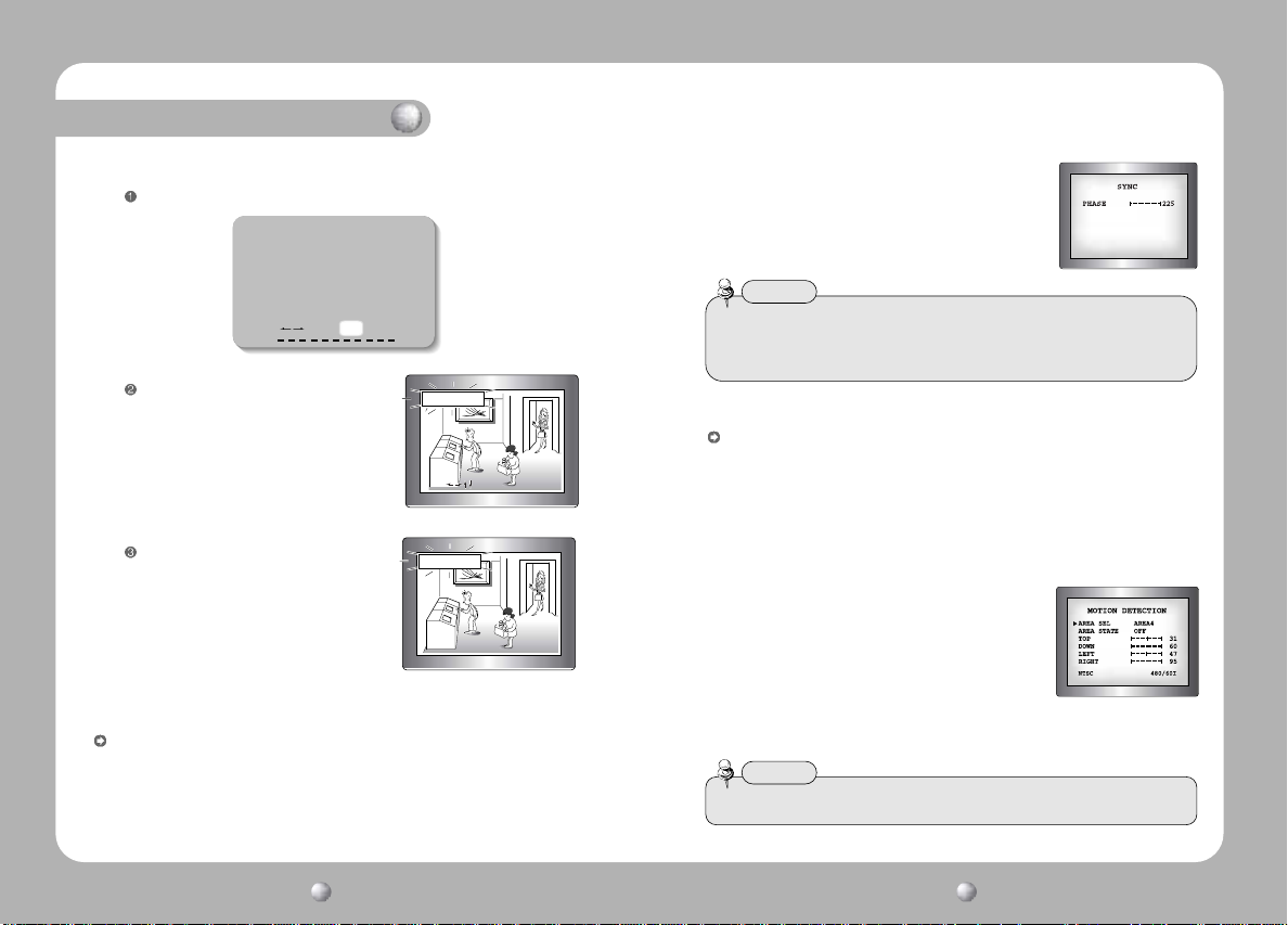
Camera Operation
to Locate, then SETto Locate, then SETto Locate, then SET
5) When a name has been chosen, please select a position for the name display.
Please move the cursor onto 'POS' and then press the SETUP button.
Camera ID
ABCDEFGHIJKLM
NOPQRSTUVWXYZ
abcdefghijklm
nopqrstuvwxyz
-. 123456789
CLR POS END
The name will appear at the top left hand
corner.
Please find the position you wish to display the
name by using the 4 directional buttons,
FRONT DOOR
FRONT DOOR
and then press the SETUP button.
6) Please select 'END' and then press the SETUP button to complete ID input.
SYNC : Two SYNCHRONIZATION modes are available INTERNAL and EXTERNAL
LINE-LOCK. In LINE-LOCK mode, it synchronizes the video signal between
cameras without a synchronous generator. The line-lock synchronization is only
used in the areas of 60Hz (NTSC Models) / 50Hz (PAL Models).
- INT : Internal synchronization - LL : External line-lock synchronization
• If you choose ‘LL’, you can adjust the desired phase.
Press the SET button.
• You can adjust the desired phase from 0 to 359.
Notes
• When the power frequency is 50Hz, you can not use line-lock mode (NTSC Models).
• When the power frequency is 60Hz, you can not use the line-lock mode (PAL Models).
• ‘Sync.’ mode is fixed to ‘INT’ in DC 12V input power.
MOTION DETECTION:
This product has a feature that allows you to observe movements of objects in 4
different areas on the screen, and the words 'MOTION DETECTED' appear on the
screen when movement is detected; hence a single individual can conduct
supervision efficiently. The camera detects an object's movement by sensing
disparity of outline, and level of brightness and color.
• Please press the SETUP button.
- OFF : MOTION DETECTION mode is cancelled.
- ON : Any motion in the selected areas is observed.
• Please select the area you wish to observe from the 4
areas in AREA SEL mode.
• Please select ON mode for the chosen area.
• Please adjust the size of the area to be observed by
using the UP, DOWN, LEFT or RIGHT button.
•Please press the SETUP button to save the changes and complete the setting.
Notes
•There is no ‘MD’ output signal. ‘MD’ is on screen display only words.
COLOR CCD CAMERA User’s Manual
32
COLOR CCD CAMERA User’s Manual
33
Page 18
Camera Operation
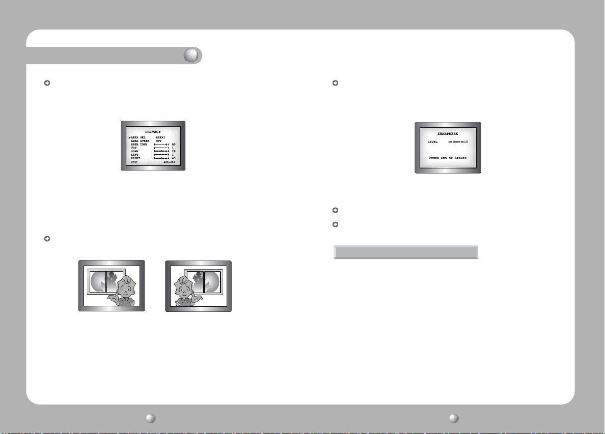
PRIVACY: This modes conceals the areas you do not wish to appear on the screen.
- OFF : Cancels the PRIVACY mode.
- ON : Operates the PRIVACY mode.
•Please press the SETUP button.
•Please select the area you do not wish to appear from the 4 areas in AREA SEL mode.
•Please select ON mode for the chosen area.
•Please adjust the size of the area to be concealed by using the UP, DOWN, LEFT or
RIGHT button.
MIRROR
- ON : Sets a horizontal image inversion. - OFF : Cancels the inversion.
MIRROR ON MIRROR OFF
SHARPNESS: The outline of the video image becomes cleaner and more distinctive
as the level of SHARPNESS increases. If the level goes up excessively,
however, it may affect the video image and generate noise.
•Please press the SETUP button.
•The available range of level is 0 ~ 31.
RESET: Returns to the level which was set by the manufacturer for shipment.
RETURN: Returns to the SETUP menu.
EXIT
Saves all the setting menus and then exits.
COLOR CCD CAMERA User’s Manual
34
COLOR CCD CAMERA User’s Manual
35
Page 19
Troubleshooting
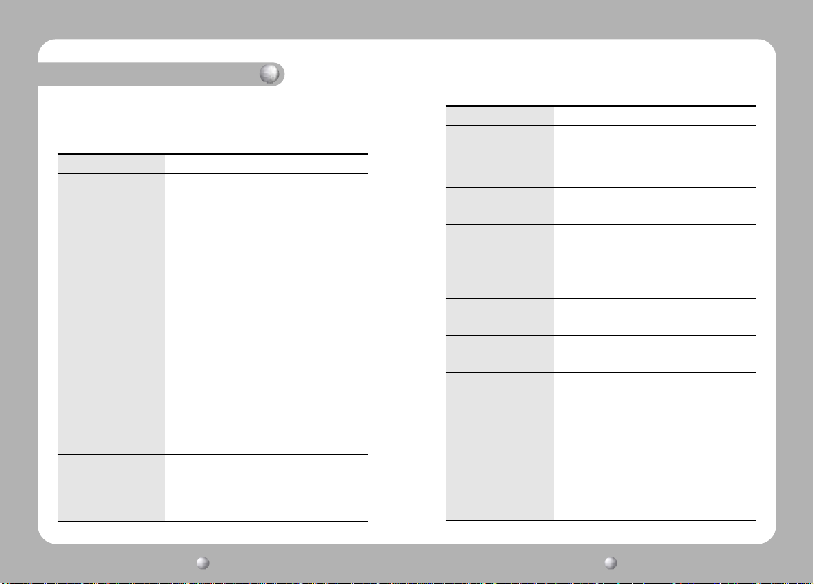
If you have trouble operating your camera, refer to the following table. If the
guidelines do not enable you to solve the problem, contact an authorized
technician.
Problem
Nothing appears on
the screen.
The video image is
not clear.
The screen is dark.
There is a problem with the
camera operation. The
camera surface is too hot
and black stripes appear on
the screen.
• Please check the power connection.
• Please check the video signal line connection.
• Please check and make sure that the auto lens
switch is set to DC (VIDEO) when using a DC
(VIDEO) lens.
• Please check the Brightness of Auto Iris lens.
• Please check if the lens is clean.
Please clean the lens with a clean cloth or brush.
• Please adjust the contrast feature of the
monitor.
• Please make sure that the screen is not exposed
directly to a bright light.
Please move the camera if necessary.
• Please readjust the back focus of the camera.
• Please adjust the contrast feature of the monitor.
• If you have an intermediate device, set the 75Ω/
Hi-z properly, and check the terminals. (refer to
page 18)
• Please check if an auto iris lens is being used
and adjust the brightness level.
• Please check if an appropriate power source to
the camera complies with the manufacturer's
standard requirement, or if the voltage keeps
changing.
Solution
Problem
The MOTION
DETECTION function
is not working.
Colors are not quite
right.
The screen is
flickering.
L/L mode isn't able to
be selected.
L/L mode is not
available.
SENS-UP function is
not working.
Solution
• Please check if 'MOTION DETECTION' mode is
turned on.
• Please check if the MD LEVEL is too low.
• Please check the setting of the MD AREA.
• Please check the 'WHITE BAL' setting. (Please
refer to page 25)
• Please check if the camera is facing directly into
sunlight or fluorescent light.
• Please check if an auto iris lens is being used.
• Please check the connection of the lens connector
cable.
• Have you connected your camera to DC power
source? Connect it to AC power source.
• Please check the frequency of power supply
(60Hz for NTSC, 50Hz for PAL).
• Please check if the AGC menu is set to the OFF
position.
• Please check if the SHUTTER menu is set to
MANUAL mode.
• Please check the limit of SENS-UP AUTO mode.
COLOR CCD CAMERA User’s Manual
36
COLOR CCD CAMERA User’s Manual
37
Page 20
Specifications
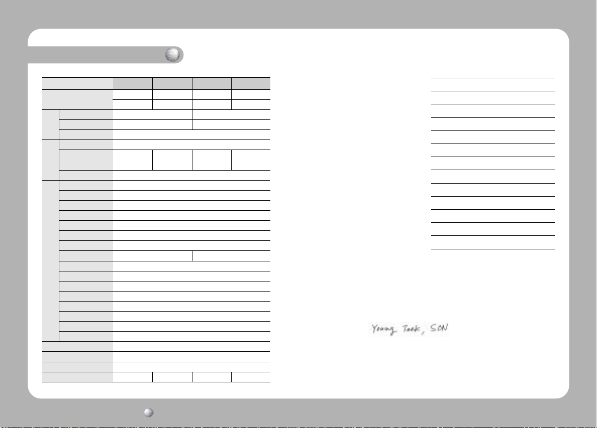
Item
Power Source
Total Pixels
C
C
Effective Pixels
D
Size
Scanning System
S
Synchronization
y
n
c
Frequency
Resolution
Video Output
S/N (Y signal)
Min. Illumination
Gain Control
E
White Balance
L
E
Backlight Compensation
C
Electronic shutter speed
T
R
SENS-Up
I
C
O.S.D
A
Motion Detection
L
SSNR
MIRROR
Privacy Function
Sharpness
IRIS Control
Lens Mount
Dimension
Operationg temperature/Humidity
Weight
SDC-313ANA SDC-313AND SDC-313APA SDC-313APD
AC24V, 60Hz DC12V AC24V, 50Hz DC12V
3.5W(Max) 2.5W(Max) 3.5W(Max) 2.5W(Max)
811(H) x 508(V) 795(H) x 596(V)
768(H) x 494(V) 752(H) x 582(V)
INT/LL Selectable
0~359°(Adjustable) 0~359°(Adjustable)
Horizontal:15.734 KHz Vertical :59.94Hz
1.0Vp-p/75Ω 1.0Vp-p/75Ω
AUTO/MANUAL(1/60~1/120,000 sec)
340g 310g 340g 310g
1/3'' Super HAD color CCD
2:1 Interlace
INT/LL Selectable
INT
Horizontal: 15.625 KHz Vertical : 50Hz
More than 530 TV Lines
50dB (AGC OFF, Weight ON)
0.3Lux/F1.2, 0.002Lux/F1.2(Sens-UP X128)
LOW/MIDDLE/HIGH/OFF Selectable
ATW/AWC/MANUAL(1,800°K~10,500°K)
LOW/MIDDLE/HIGH/OFF Selectable
AUTO/MANUAL(1/50~1/120,000 sec)
OFF/AUTO (selectable limit X2 ~X128)
Built-in
ON / OFF (4 Programmable Zone)
LOW/MIDDLE/HIGH/OFF Selectable (Noise Control)
OFF/ON(Horizontal Image Inversion)
ON / OFF (4 Programmable Zone)
ON/OFF (Level adjustable)
DC / VIDEO
C/CS Mount (Changeable)
58(W) x 52(H) x 121(D)mm
-10°C ~ +50°C [14°F~122°F] / 30~80% RH
DECLARATION OF CONFORMITY
Application of Council Directive(s) 89 / 336 / EEC
Manufacturer's Name SAMSUNG TECHWIN CO., LTD
Manufacturer's Address SAMSUNG TECHWIN CO., LTD
42, SUNGJU-DONG CHANGWON-CITY,
KYUNGNAM, KOREA, 641-120
European Representative Name
INT
European Representative Address
Equipment Type/Environment CCTV Camera
Model Name SDC-313APA, SDC-313APD
Beginning Serial NO. S5110001
Year of Manufacture 2005. 11. 1
Conformance to EN 50081-1 : 1992
EMC-Directive 89/336 EEC and 92/31/EEC
EN 50130-4 : 1996
We, the undersigned, hereby declare that the equipment specified above conforms
to the above Directive(s).
Manufacturer SAMSUNG TECHWIN CO., LTD
Legal Representative in Europe
Signature Signature
Full Name YOUNG TAEK SON Full Name
Position QUALITY CONTROL MANAGER Position
Place CHANGWON, KOREA Place
Date 2005. 11. 1 Date
COLOR CCD CAMERA User’s Manual
38
 Loading...