

Sony DSC-H50, RMT-DSC2 Service Manual
DSC-H50
RMT-DSC2
SERVICE MANUAL
Ver. 1.1 2008.05
Revision History
Revision History
Internal memory
Internal memory
ON BOARD
ON BOARD
Revised-1
Replace the previously issued
SERVICE MANUAL 9-852-286-31
with this Manual.
Photo: Black
Link
Link
SPECIFICATIONS
BLOCK DIAGRAMS
LEVEL 2
US Model
Canadian Model
AEP Model
UK Model
E Model
Australian Model
Hong Kong Model
Chinese Model
Korea Model
Argentine Model
Brazilian Model
Thai Model
Japanese Model
Tourist Model
PRINTED WIRING BOARDS
SERVICE NOTE
DISASSEMBLY
• Precaution on Replacing the SY-201 Board
The components identified by
mark 0 or dotted line with
mark 0 are critical for safety.
Replace only with part number specified.
Les composants identifiés par une
marque 0 sont critiques pour la
sécurité.
Ne les remplacer que par une pièce
portant le numéro spécifié.
FRAME SCHEMATIC DIAGRAM
SCHEMATIC DIAGRAMS
REPAIR PARTS LIST
DIGITAL STILL CAMERA
DSC-H50_L2
Sony EMCS Co.
2008E0800-1
© 2008.05
Published by Kohda TEC9-852-286-32

SPECIFICATIONS
Camera
[System]
Image device: 7.70 mm (1/2.3 type) color CCD, Primary color filter
• Only 7.30mm (1/2.5type equivalent) area is used in the camera.
Total pixel number of camera: Approx. 10.3 Megapixels
Effective pixel number of camera: Approx. 9.1 Megapixels
Lens: Carl Zeiss Vario-Tessar 15Å~ zoom lens
f = 5.2 - 78 mm (31 - 465 mm (35 mm film equivalent))
F2.7(W) - 4.5(T)
Exposure control: Automatic exposure, Shutter
speed priority, Aperture priority, Manual exposure,
Scene Selection (10 modes)
White balance: Automatic, Daylight, Cloudy,
Fluorescent 1,2,3, Incandescent, Flash, One push
File format (DCF compliant):
Still images: Exif Ver. 2.21 JPEG compliant, DPOF compatible
Movies: MPEG1 compliant (Monaural)
Recording media: Internal Memory (approx. 15MB),
“Memory Stick Duo”
Flash: Flash range (ISO sensitivity
(Recommended exposure Index) set to Auto):
Approx. 0.2 to 9.1m (77/8inches to 29feet 103/8inches) (W)/
approx. 1.2 to 5.5m (3feet 111/4inches to 18feet 5/8inches) (T)
Viewfinder: Electric view finder (color)
[Input and Output connectors]
Multi connector: Video output
Audio output (Monaural)
USB communication
USB communication: Hi-Speed USB (USB 2.0 compliant)
[LCD screen]
LCD panel: 7.5cm (3.0type) TFT drive
Total number of dots: 230 400 (960 Å~ 240) dots
[Finder]
Panel: 0.5cm (0.2type) color
Total number of dots: Approx. 200 000 dots equivalent
[Power, general]
Power: Rechargeable battery pack
NP-BG1, 3.6V
NP-FG1 (not supplied), 3.6V
AC-LS5K AC Adaptor (not supplied), 4.2V
Power consumption (during shooting, LCD screen on): 1.1 W
Operating temperature: 0 to 40°C (32 to 104°F)
Storage temperature: –20 to +60°C (–4 to +140°F)
Dimensions: 116.1 × 81.4 × 86.0mm
(45/8 × 31/4 × 31/2inches) (W/H/D, excluding protrusions)
Mass: Approx. 547g (1lb 3.3oz)
(including NP-BG1 battery pack, strap, etc.)
Microphone: Monaural
Speaker: Monaural
Exif Print: Compatible
PRINT Image Matching III: Compatible
PictBridge: Compatible
BC-CSGB/BC-CSGC battery charger
Power requirements: AC 100V to 240V, 50/60Hz,
2.6W (BC-CSGB)/2W (BC-CSGC)
Output voltage: DC 4.2V, 0.25A
Operating temperature: 0 to 40°C (32 to 104°F)
Storage temperature: –20 to +60°C (–4 to +140°F)
Dimensions: Approx. 62 × 24 × 91mm
(2 1/2 × 31/32 × 35/8 inches) (W/H/D)
Mass: Approx. 75g (2.7oz)
Rechargeable battery pack NP-BG1
Used battery: Lithium-ion battery
Maximum voltage: DC 4.2V
Nominal voltage: DC 3.6V
Capacity: 3.4Wh (960mAh)
Design and specifications are subject to change without notice.
DSC-H50_L2
— 2 —

Danger of explosion if battery is incorrectly replaced.
Replace only with the same or equivalent type.
CAUTION
SAFETY-RELATED COMPONENT WARNING!!
COMPONENTS IDENTIFIED BY MARK 0 OR DO TTED LINE WITH
MARK 0 ON THE SCHEMATIC DIAGRAMS AND IN THE PARTS
LIST ARE CRITICAL TO SAFE OPERATION. REPLACE THESE
COMPONENTS WITH SONY PARTS WHOSE PART NUMBERS
APPEAR AS SHOWN IN THIS MANUAL OR IN SUPPLEMENTS
PUBLISHED BY SONY.
SAFETY CHECK-OUT
After correcting the original service problem, perform the following
safety checks before releasing the set to the customer.
1. Check the area of your repair for unsoldered or poorly-soldered
connections. Check the entire board surface for solder splashes
and bridges.
2. Check the interboard wiring to ensure that no wires are
"pinched" or contact high-wattage resistors.
3. Look for unauthorized replacement parts, particularly
transistors, that were installed during a previous repair . Point
them out to the customer and recommend their replacement.
4. Look for parts which, through functioning, show obvious signs
of deterioration. Point them out to the customer and
recommend their replacement.
5. Check the B+ voltage to see it is at the values specified.
6. Flexible Circuit Board Repairing
•Keep the temperature of the soldering iron around 270˚C
during repairing.
• Do not touch the soldering iron on the same conductor of the
circuit board (within 3 times).
• Be careful not to apply force on the conductor when soldering
or unsoldering.
ATTENTION AU COMPOSANT AYANT RAPPORT
À LA SÉCURITÉ!
LES COMPOSANTS IDENTIFÉS P AR UNE MARQ UE 0 SUR LES
DIAGRAMMES SCHÉMA TIQ UES ET LA LISTE DES PIÈCES SONT
CRITIQUES POUR LA SÉCURITÉ DE FONCTIONNEMENT. NE
REMPLACER CES COMPOSANTS QUE PAR DES PIÈSES SONY
DONT LES NUMÉROS SONT DONNÉS DANS CE MANUEL OU
DANS LES SUPPÉMENTS PUBLIÉS PAR SONY.
Unleaded solder
Boards requiring use of unleaded solder are printed with the leadfree mark (LF) indicating the solder contains no lead.
(Caution: Some printed circuit boards may not come printed with
the lead free mark due to their particular size.)
: LEAD FREE MARK
Unleaded solder has the following characteristics.
• Unleaded solder melts at a temperature about 40°C higher than
ordinary solder.
Ordinary soldering irons can be used but the iron tip has to be
applied to the solder joint for a slightly longer time.
Soldering irons using a temperature regulator should be set to
about 350°C.
Caution: The printed pattern (copper foil) may peel away if the
heated tip is applied for too long, so be careful!
• Strong viscosity
Unleaded solder is more viscous (sticky , less pr one to flow) than
ordinary solder so use caution not to let solder bridges occur such
as on IC pins, etc.
•Usable with ordinary solder
It is best to use only unleaded solder but unleaded solder may
also be added to ordinary solder.
DSC-H50_L2
— 3 —
ENGLISH JAPANESE
1. SERVICE NOTE
ENGLISH JAPANESE
1-1. PRECAUTION ON REPLACING THE SY-201 BOARD
DESTINATION DATA
When you replace to the repairing board, the written destination data of repairing board also might be changed to original setting.
Refer to Service Manual ADJ, and perform “DESTINATION DATA WRITE”.
USB SERIAL No.
The set is shipped with a unique ID (USB Serial No.) written in it.
This ID has not been written in a new board for service, and therefore it must be entered after the board replacement.
Refer to Service Manual ADJ, and perform “USB SERIAL No. INPUT”.
1-2. SELF-DIAGNOSIS FUNCTION
1-2-1. Self-diagnosis Function
When problems occur while the unit is operating, the self-diagnosis
function starts working, and displays on the LCD screen what to
do.
Details of the self-diagnosis functions are provided in the Instruction
manual.
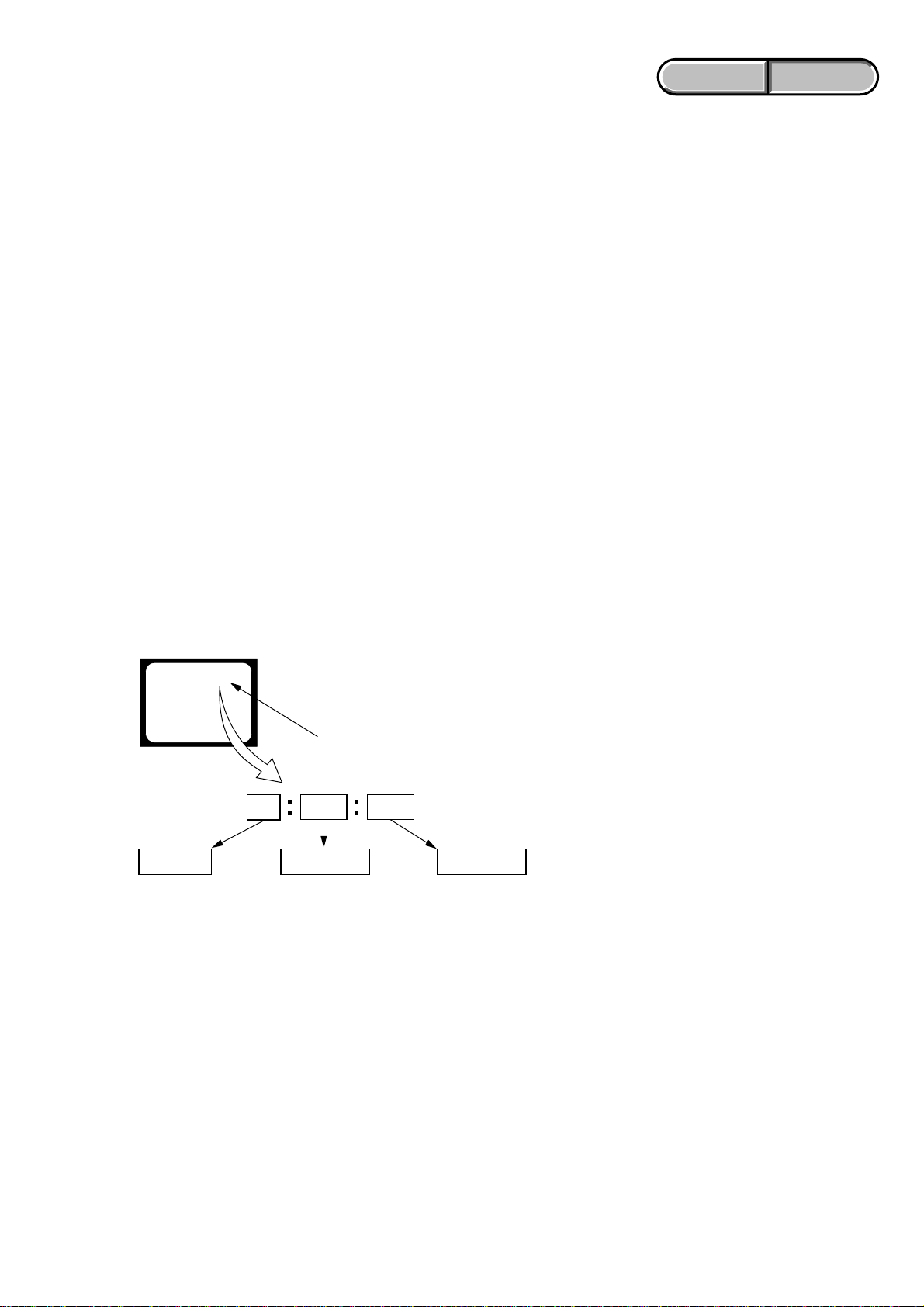
LCD screen
Blinks at 3.2 Hz
0 0
Refer to “1-2-3. Self-diagnosis Code Table”.
Repaired by:
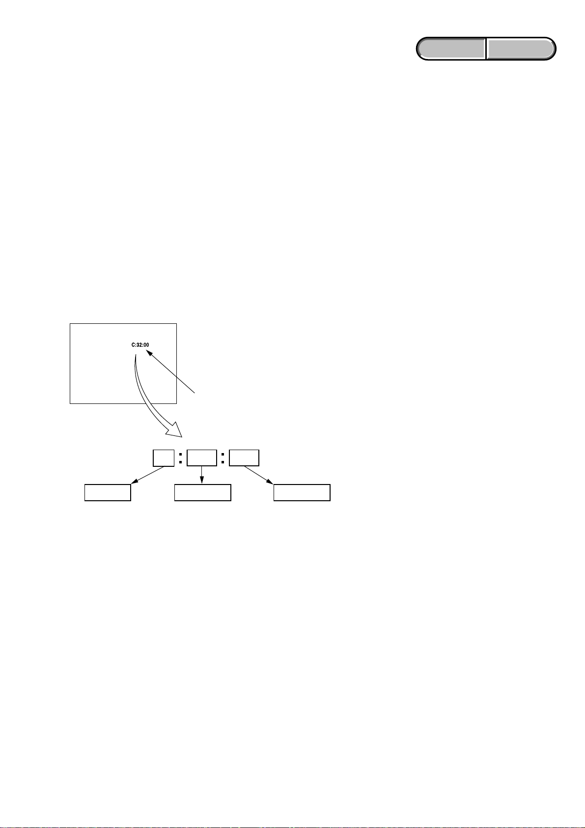
C : Corrected by customer
E : Corrected by service
engineer
3 2C
Block
Indicates the appropriate
step to be taken.
E.g.
13 ....Format t h e “ Memory Stick Duo”.
32 ....Turn on power again.
1-2-2. Self-diagnosis Display
When problems occur while the unit is operating, the LCD screen
shows a 4-digit display consisting of an alphabet and numbers, which
blinks at 3.2 Hz. This 5-character display indicates the “repaired
by:”, “block” in which the problem occurred, and “detailed code”
of the problem.
Detailed Code
DSC-H50_L2
1-1
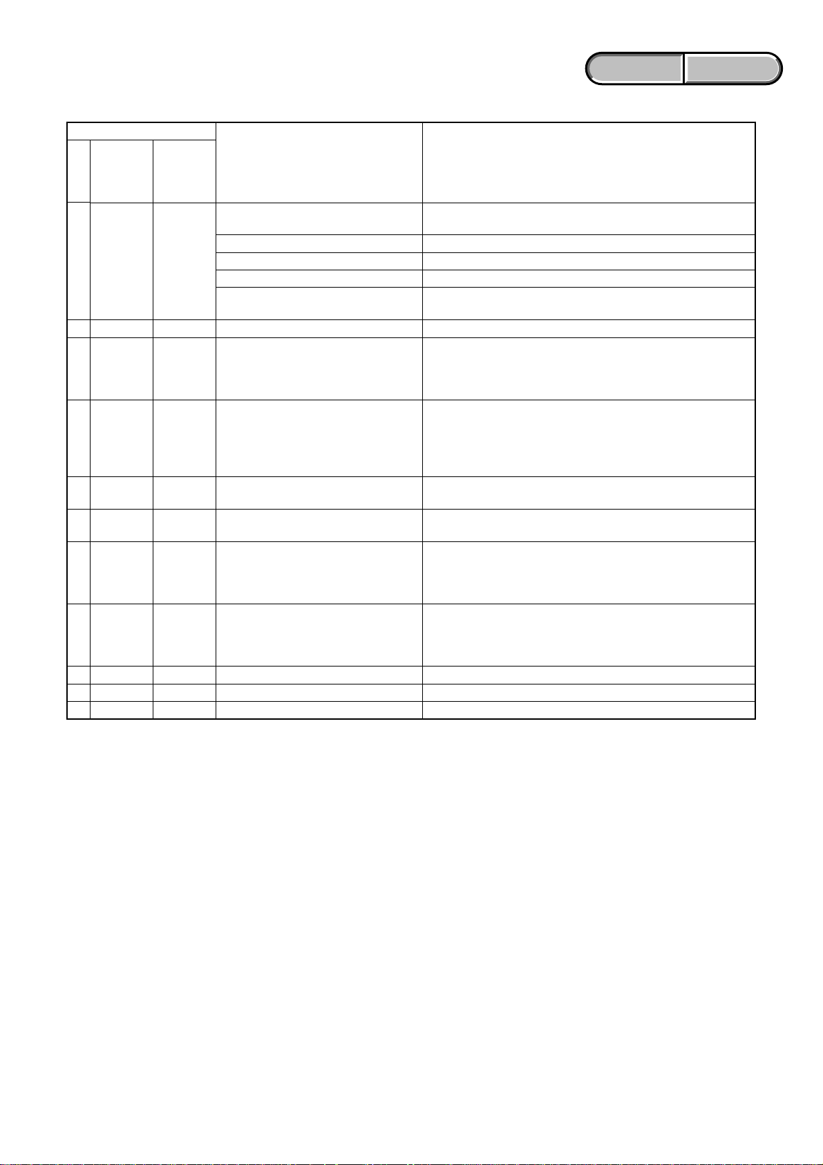
1-2-3. Self-diagnosis Code Table
Self-diagnosis Code
ENGLISH JAPANESE
ENGLISH JAPANESE
Block
Function
Repaired by:
C
13
C
32
E
61
E
61
E
62
E
62
E
62
E
62
E
62
E
91
E
92
Note: After repair, be sure to perform “1-3. PROCESS AFTER FIXING FLASH ERROR”.
Detailed
Code
01
01
00
10
02
10
11
12
20
01
00
Symptom/State
The internal memory has experienced a
format error.
“Memory Stick Duo” is unformatted.
“Memory Stick Duo” is broken.
“Memory Stick Duo” type error
The camera cannot read or write data
on the “Memory Stick Duo”.
Trouble with hardware
Difficult to adjust focus
(Cannot initialize focus)
Zoom operations fault
(Cannot initialize zoom lens.)
Abnormality of IC for steadyshot.
Lens initializing failure.
Lens overheating (PITCH).
Lens overheating (YAW).
Abnormality of thermistor.
Abnormality when flash is being charged.
Non-standard battery is used.
Format the internal memory.
Format the “Memory Stick Duo”.
Insert a new “Memory Stick Duo”.
Insert a supported “Memory Stick Duo”.
Turn the power off and on again, or taking out and inserting the
“Memory Stick Duo” several times.
Turn the power off and on again.
Retry turn the power on by the power switch. If it does not
recover, check the focus reset sensor of lens block (pin wj of
CN401 on the SY-201 board). If it is OK, check the focus motor
drive IC (IC401 on the SY-201 board).
Retry turn the power on by the power switch. Check the zoom
reset sensor of lens block (pin qj of CN401 on the SY-201
board), if zooming is performed when the zoom button is
operated. If it is OK, check the zoom motor drive IC (IC401 on
the SY-201 board).
Check or replacement of the IC for steadyshot (IC503 on the SY201 board).
Check or replacement of the IC for steadyshot (IC503 on the SY201 board).
Check the HALL element (PITCH) of optical image stabilizer
(pin eg, ej of CN401 on the SY-201 board). If it is OK, check
PITCH/YAW angular velocity sensor (SE502 on the SY-201
board) peripheral circuits.
Check the HALL element (YAW) of optical image stabilizer (pin
e;, es of CN401 on the SY-201 board). If it is OK, check
PITCH/YAW angular velocity sensor (SE501 on the SY-201
board) peripheral circuits.
Replacement of lens block.
Checking of flash unit or replacement of flash unit. (Note)
Use the compatible battery only.
Correction
DSC-H50_L2
1-2

ENGLISH JAPANESE
ENGLISH JAPANESE
1-3. PROCESS AFTER FIXING FLASH ERROR
When “FLASH error” (Self-diagnosis Code E : 91 : 01) occurs, to prevent any abnormal situation caused by high voltage, settin g of the flash
is changed automatically to disabling charge and flash setting.
After fixing, this setting needs to be deactivated. Flash error code can be initialized by the operations on the HOME screen.
Method for Initializing the Flash Error Code
Initialize
Initializes the setting to the default setting. Even if you execute this function, the images
stored in the internal memory are retained.
1 Select [Initialize] with v/V on the control button, then press z.
The message “Initialize all settings” appears.
2 Select [OK] with v, then press z.
The settings are reset to the default setting.
To cancel initializing
Select [Cancel] in step 2, then press z.
Be sure not to power off the camera while initializing.
1-4. METHOD FOR COPYING OR ERASING THE DATA IN INTERNAL MEMORY
The data can be copied/erased by the operations on the HOME screen. (When erasing the data, execute formatting the internal memory.)
Note 1: When replacing the SY-201 board, erase the data in internal memory of the board before replacement.
Note 2: When replacing the SY-201 board, execute formatting and initialize the internal memory after replacement.
Method for Copying the Data in Internal Memory
Copy
Copies all images in the internal memory to a “Memory Stick Duo”.
1 Insert a “Memory Stic k Duo” ha ving sufficient free capacity.
2 Select [Copy] with v/V on the control button, then press z .
The message “ A l l data in internal memory will be copied” appears.
3 Select [OK] with v, then press z.
Copying starts.
To cancel copying
Select [Cancel] in step 3, then press z.
Use a fully charged battery pack. If you attempt to copy image files using a battery pack with little
remaining charge, the battery pack may run out, causing copying to fail or possibly corrupting the data.
You cannot select images to copy.
The original images in the internal memory are retained even after copying. To delete the contents of the
internal memory, remove the “Memory Stick Duo” after copying, then format the internal memory
([Format] in [Internal Memory Tool]).
A new folder is created on the “Memory Stick Duo” and all the data will be copied to it. You cannot
choose a specific folder and copy images to it.
The (Print order) marks on the images are not copied.
Method for Formatting the Internal Memory
This item does not appear when a “Memory Stick Duo” is inserted in the camera.
Format
Formats the internal memory.
Note that formatting permanently erases all data in the internal memory, including even protected images.
1 Select [Format] with v/V on the control button, then press z.
The message “All data in internal memory will be erased” appears.
2 Select [OK] with v, then press z.
Formatting starts.
To cancel formatting
Select [Cancel] in step 2, then press z.
DSC-H50_L2
1-3
ENGLISH JAPANESE
ENGLISH JAPANESE
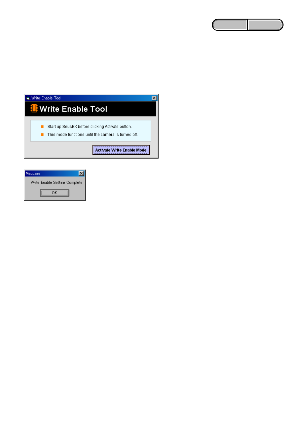
1-5. HOW TO WRITE DATA TO INTERNAL MEMORY
Usually, the camera has been set so as to disable the data writing from the PC to the internal memory of the camera.
This setting must be changed temporarily when the data is to be written to the internal memory such as a case after the board replacement.
To change the setting, use the write enable tool “WriteEnableTool.exe”.
Data writing method
1) Connect the PC to the camera (USB mode: Mass Storage), and switch the driver to the “Sony Seus USB Driver”.
2) Start the Write Enable Tool and the SeusEX.
3) Click the [Activate Write Enable Mode] button of the Write Enable Tool.
4) Upon completion of the setting change, the following message will be displayed.
5) Return the driver to the original one, and connect the PC to the camera (USB mode: Mass Storage).
6) Write the data read out into the PC to the internal memory of the camera.
7) Disconnect the PC from the camera, and turn off the camera.
Note: By turning off the camera, the write enable setting is reset.
DSC-H50_L2
1-4
ENGLISH JAPANESE
1. SERVICE NOTE
ENGLISH JAPANESE
1-1. SY-201基板交換時の注意
仕向けデータ
補修用基板と交換する時,補修用基板に書かれている仕向けデータは元の設定と違っている場合があります。
ADJ編を参照して,「DESTINATIONDATAWRITE」を行ってください。
USBシリアルNo.
セットは,1台毎に異なる固有のID(USBSerialNo.)を書き込んだ後,出荷されています。
新品の補修用基板には,このIDが書き込まれていないので,基板交換後にIDを入力する必要があります。
ADJ編を参照して,「USBSERIALNo.INPUT」を行ってください。
1-2. 自己診断機能
1-2-1. 自己診断機能について
本機の動作に不具合が生じたとき,自己診断機能が働き,
LCD画面に,どう処置したらよいか判断できる表示を行い
ます。自己診断機能については取扱説明書にも掲載されて
います。
1-2-2. 自己診断表示
本機の動作に不具合が生じたとき,LCD画面にアルファベッ
トと4桁の数字が表示され,3.2Hzで点滅します。この5文字
の表示によって対応者分類および不具合の生じたブロックの
分類,不具合の詳細コードを示します。
LCD画面
C : 3 2 : 00
3.2Hz点滅
3 2C
対応者分類
C :お客さま自身で対応
E :サービスエンジニア
で対応 デュオ”をフォーマッ
ブロック分類
対応方法の違いにより分類
例 13 ・・・“メモリースティック
トする
32 ・・・電源を入れ直す
0 0
詳細コード
「1-2 -3 . 自己診断コード表」
を参照
DSC-H50_L2
1-5
1-2-3. 自己診断コード表
自己診断コード
対
ブロック
応
機能
者
C
13
C
32
E
61
E
61
E
62
E
62
E
62
E
62
E
62
E
91
E
92
Note:交換後は,必ず「1-3.フラッシュエラー発生時の対処法」を行って下さい。
詳細
コード
01
01
00
10
02
10
11
12
20
01
00
症状/状態
内蔵メモリにフォーマットエラーが
あった。
フォーマットしていないメモリー
スティックデュオを入れた。
メモリースティックデュオが
壊れている。
メモリースティックデュオの
タイプエラーを検出した。
メモリースティックデュオが
読み/書きできない。
ハードウェアトラブルを検出した。
フォーカスが合いにくい。
(フォーカスの初期化ができない)
ズーム動作の異常。
(ズームレンズの初期化ができな
い)
手振れ補正用ICの異常。
手振れ補正用ICの異常。
(レンズ初期化異常)
レンズオーバーヒート(PITCH)
レンズオーバーヒート(YAW)
サーミスタの異常。
フラッシュの充電異常。
規定外の充電池が使用された。
内蔵メモリをフォーマットする。
メモリースティックデュオをフォーマットする。
新しいメモリースティックデュオに交換する。
規格内のメモリースティックデュオを挿入する。
電源の入れ直し,またはメモリースティックデュオ
の挿し/外しを数回試す。
電源を入れ直す。
操作スイッチの電源を入れ直す。
復帰しない場合はレンズブロックのフォーカスリセットセ
ンサ(SY-201基板CN401wjピン)を点検する。異常なけ
ればフォーカスモータ駆動IC(SY-201基板IC401)を点検
する。
操作スイッチの電源を入れ直す。
ズームボタンを操作したときにズーム動作をすればレンズ
ブロックのズームリセットセンサ(SY-201基板CN401qj
ピン)を点検する。異常なければズームモータ駆動IC
(SY-201基板IC401)を点検する。
手振れ補正用IC(SY-201基板IC503)を点検または交換す
る。
手振れ補正用IC(SY-201基板IC503)を点検または交換す
る。
光学手振れ補正ブロックのホール素子(PITCH)(SY-201
基板CN401eg,ejピン)を点検する。異常なければ
PITCH/YAW角速度センサ(SY-201基板SE502)周辺の回
路を点検する。
光学手振れ補正ブロックのホール素子(YAW)(SY-201
基板CN401e;,esピン)を点検する。異常なければ
PITCH/YAW角速度センサ(SY-201基板SE501)周辺の回
路を点検する。
レンズブロックを交換する。
フラッシュユニットを点検または交換する。(Note)
規定の充電池を使用する。
ENGLISH JAPANESE
ENGLISH JAPANESE
対応/方法
DSC-H50_L2
1-6
ENGLISH JAPANESE
ENGLISH JAPANESE
1-3. フラッシュエラー発生時の対処法
本機はフラッシュエラー(自己診断コードE:91:01)が発生した場合,高電圧による異常を防止するために自動的にフラッシュ
充電および発光禁止の設定になります。
フラッシュエラー発生後はエラーの解除を行う必要があります。エラーの解除はホーム画面から初期化操作を実行することによ
り行います。
設定リセット
お買い上げ時の設定に戻します。
[設定リセット]を実行しても、内蔵メモリーに記録されている画像は削除されません。
1
コントロールボタンの で[設定リセット]を選び、中央の を押す。
「全ての設定内容をリセットします」というメッセージが表示される。
2
で[実行]を選び、中央の を押す。
設定リセットが実行される。
設定リセットを中止するには
手順2で、[キャンセル]を選び、中央の を押す。
設定リセット中は電源が切れないようにご注意ください。
/
1-4. 内蔵メモリのデータコピーおよび消去方法
内蔵メモリのデータコピーまたは消去はホーム画面の操作から実行可能です。(消去する場合は内蔵メモリの初期化を行いま
す。)
Note1:SY-201基板交換の際は,基板交換前に内蔵メモリのデータを消去して下さい。
Note2:SY-201基板交換の際は,基板交換後に内蔵メモリのフォーマットおよび初期化を実行して下さい。
内蔵メモリのコピー方法
コピー
内蔵メモリーに記録した画像を、メモリースティック デュオに一括コピーします。
1
充分な空き容量のあるメモリースティック デュオを本体に入れる。
2
コントロールボタンの
「内蔵メモリーのデータがすべてコピーされます」というメッセージが表示される。
3
で[実行]を選び、中央の を押す。
コピーが実行される。
コピーを中止するには
手順3で、[キャンセル]を選び、中央のz を押す。
•
充分に充電したバッテリーをご使用ください。残量の少ないバッテリーを使用して画像ファイ
ルをコピーすると、バッテリー切れのためデータを転送できなかったり、データを破損するお
それがあります。
•
画像ごとのコピーはできません。
•
データをコピーしても、内蔵メモリー内のデータは削除されません。内蔵メモリーの内容を消
去するには、コピー後にメモリースティックデュオを本体から取りはずし、[内蔵メモリー
ツール]の[フォーマット]を行ってください。
•
データをコピーするとメモリースティックデュオ内に新しいフォルダが作成されます。コ
ピー先のフォルダを指定することはできません。
•
データのコピーを行っても、
で[コピー]を選び、中央の を押す。
/
(プリント予約)マークの設定はコピーされません。
内蔵メモリのフォーマット方法
メモリースティック デュオが本機に入っている場合は表示されません。
フォーマット
内蔵メモリーの管理領域をフォーマット(初期化)します。
フォーマットすると、プロテクトしてある画像も含めて、すべてのデータが消去され、元に戻せ
ません。
1
コントロールボタンの で[フォーマット]を選び、中央の を押す。
「内蔵メモリーのデータがすべて消去されます」というメッセージが表示される。
2
で[実行]を選び、中央の を押す。
フォーマットが実行される。
フォーマットを中止するには
手順2で、[キャンセル]を選び、中央の を押す。
/
DSC-H50_L2
1-7

ENGLISH JAPANESE
ENGLISH JAPANESE
1-5. 内蔵メモリへデータを書き戻す方法
通常は,PCからカメラの内蔵メモリへデータを書き込むことはできない設定になっています。
基板交換後などに,内蔵メモリへデータを書き戻す場合には,この設定を一時的に変更する必要があります。
設定の変更には,書き込み許可ツール(WriteEnableTool.exe)を使用します。
書き戻し方法
1) カメラとPCをマスストレージ接続し,ドライバを“SonySeusUSBDriver”に切り替える。
2) 書き込み許可ツールとSeusEXを起動する。
3) 書き込み許可ツールの[Activate Write Enable Mode]ボタンをクリックする。
4) 設定の変更が終了すると,次のメッセージが表示されます。
5) ドライバを元に戻して、カメラとPCをマスストレージ接続する。
6) PCに読み出しておいたデータをカメラの内蔵メモリに書き込む。
7) カメラとPCの接続を解除し,カメラの電源をOFFにする。
注意:カメラの電源をOFFにすることにより,書き込み許可の設定が解除されます。
DSC-H50_L2
1-8E
NOTE FOR REPAIR
2. DISASSEMBLY
• Make sure that the flat cable and flexible board are not cracked of bent at the terminal.
Do not insert the cable insufficiently nor crookedly.
• When remove a connector, don’t pull at wire of connector. It is possible that a wire is snapped.
• When installing a connector, don’t press down at wire of connector.
It is possible that a wire is snapped.
• Do not apply excessive load to the gilded flexible board.
Cut and remove the part of gilt
which comes off at the point.
(Be careful or some
pieces of gilt may be left inside)
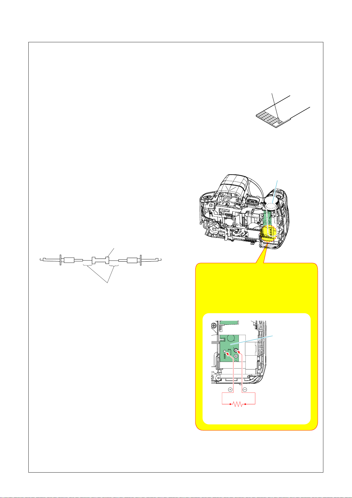
DISCHARGING OF THE ST-194 BOARD’S CHARGING CAPACITOR (C205)
The charging capacitor (C205) of the ST-194 board is charged
up to the maximum 315 V potential.
There is a danger of electric shock by this high voltage when the
capacitor is handled by hand. The electric shock is caused by
the charged voltage which is kept without dischar ging when the
main power of the unit is simply turned off. Therefore, the
remaining voltage must be discharged as described below.
Preparing the Short Jig
To preparing the short jig, a small clip is attached to each end of
a resistor of 1 kΩ /1 W (1-215-869-11).
Wrap insulating tape fully around the leads of the resistor to
prevent electrical shock.
Alminum Elect Cap
180uF 315V
(C205)
1 kΩ/1 W
Wrap insulating tape.
Note: High-voltage cautions
Discharging the Capacitor
Short-circuit between the two points with the short
jig about 10 seconds.
To avoid the spark with the metal plate,wrap the
short jig with the insulation tape.
ST-194 Board
R:1 kΩ/1 W
(Part code: 1-215-869-11)
DSC-H50_L2
2-1

2-1. IDENTIFYING PARTS
Cabinet (Front) Block
⋅ SI-115 Flexible Board
⋅ LE-042 Flexible Board
Lens Block
⋅ CCD Block
(CD-737 Flexible Board)
EVF Block
Stroboscope Block
⋅ ST-195 Flexible Board
⋅ PL-051 Board
Eye Cup
Assy (470)
Battery Holder Block
⋅ ST-194 Board
⋅ DC-111 Flexible Board
Cabinet (Rear)
Section
⋅ SW-532 Board
Side Cabinet (R) Block
⋅ JK-371 Flexible Board
- DISASSEMBLY FLOW -
2-2-1. OVERALL SECTION
⋅ Cabinet (Rear) Section
⋅ Retainer SW
⋅ Side Cabinet (R) Block
2-2-2. FRONT PANEL SECTION-1
⋅ Loudspeaker (1.3cm)
⋅ SY-201 Board
⋅ Lens Block
2-2-3. FRONT PANEL SECTION-2
⋅ Battery Holder/Stroboscope Block
⋅ Battery Holder Block
⋅ ST-195 Flexible Board
SY-201 Board
LCD Block
⋅ CK-198 Board
⋅ CK-199 Flexible Board
2-2-5. CABINET (REAR) SECTION
⋅ SW-532 Board
⋅ LCD Section
2-2-6. LCD SECTION
⋅ P Cabinet (C) Assy (470)
⋅ CK-198 Board
2-2-4. FRONT PANEL SECTION-3
⋅ Control Switch Block
⋅ Front Panel Block
DSC-H50_L2
2-2
HELP
EXPLODED VIEW
HELP
2-2. DISASSEMBLY
2-2-1. OVERALL SECTION
Follow the disassembly in the numerical order given.
1 Cabinet (Rear) Section (1-1 to 1-10)
2 Retainer SW (2-1)
3 Side Cabinet (R) Block (3-1 to 3-2)
Front Panel Section-1
(See Page 2-4)
HELP01
1-1
(#2/10)
2
Retainer SW
2-1
1-9
(Claw)
HELP01
1-2
(#2/10)
HARDWARE LIST
1
Cabinet (Rear)
Section
(See Page 2-7)
3-2
(#2/#10)
Side Cabinet (R)
3
Block
3-1
1-5
(#23/#76)
1-8
1-3
(#2/10)
1-10
1-7
1-4
(Open the
LCD panel)
1-6
(#23/#76)
DSC-H50_L2
2-3
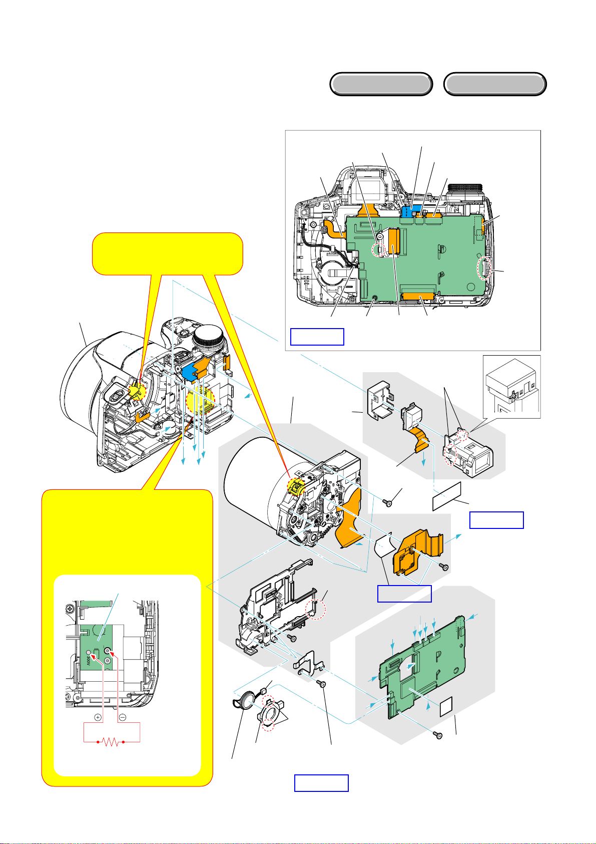
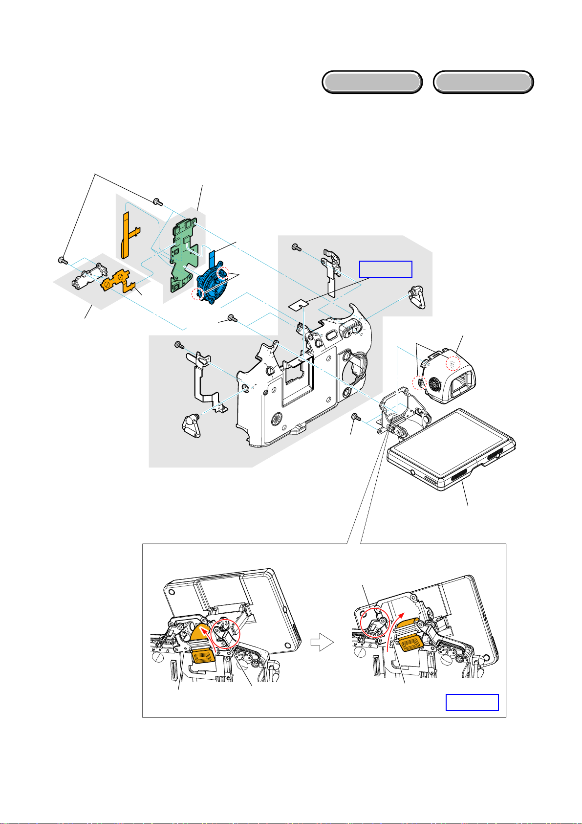
2-2-2. FRONT PANEL SECTION-1
EXPLODED VIEW
Follow the disassembly in the numerical order given.
1 Loudspeaker (1.3cm) (1-1 to 1-3)
2 SY-201 Board (2-1 to 2-16)
3 Lens Block (3-1 to 3-3)
HARDWARE LIST
Note:
Front Panel
Section-2
(See Page 2-5)
On installation of the lens block,
adjust the position of the night
shot switch.
H
H
G
G
B
HELP03
3
Lens Block
2-4
2-12
(Claw)
2-16
2-11
(#76)
2-8
SY-201
2-5
2-6
2-7
2-14
2-13
(Claw)
2-102-92-3
2-2 (Claw)
E
F
Note: High-voltage cautions
Discharging the Capacitor
Short-circuit between the two points with
the short jig about 10 seconds.
To avoid the spark with the metal plate,
wrap the short jig with the insulation tape.
ST-194 Board
R:1 kΩ/1 W
(Part code: 1-215-869-11)
D
C
1-3
1-2
1
Loudspeaker
(1.3cm)
1-1
(Claw)
HELP03
J
3-3 (Claw)
H
G
3-1 (#76)
2-15
HELP04
A
3-2
(#74)
F
I
A
D
C
E
SY-201
J
2-1
HELP02
I
B
2
SY-201 Board
DSC-H50_L2
2-4
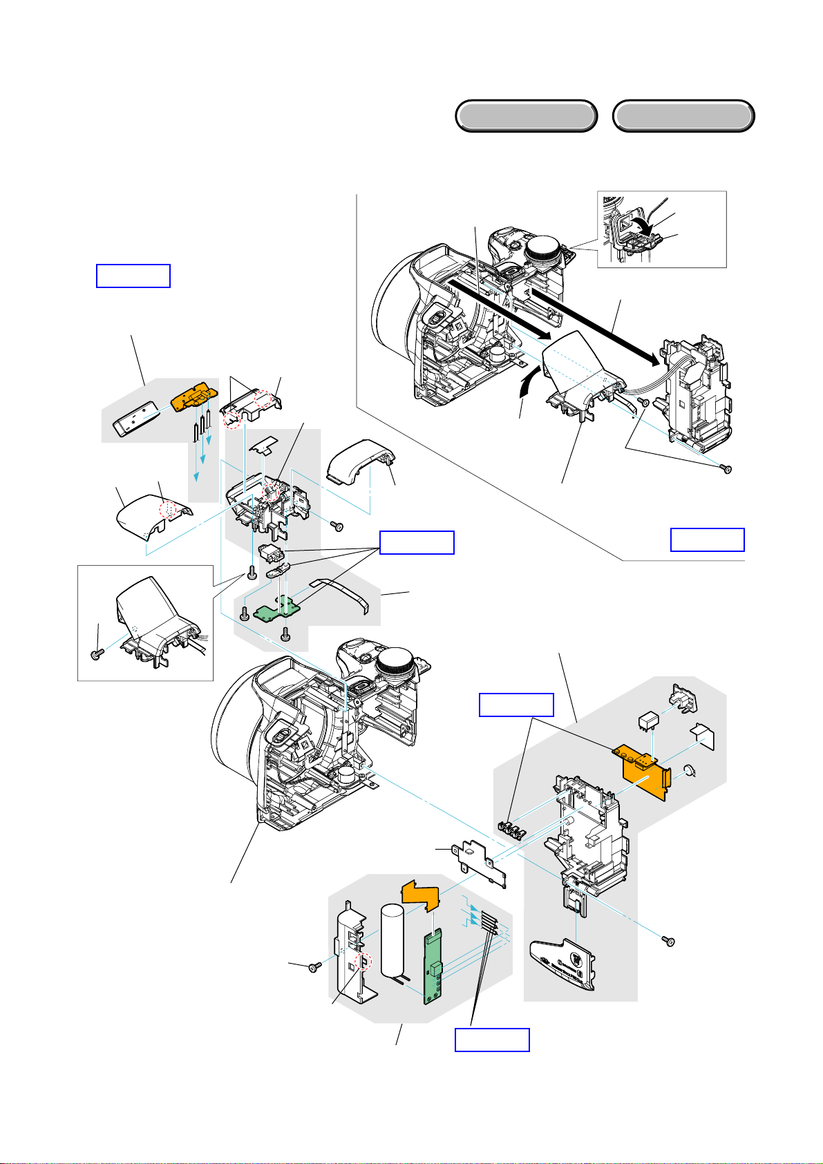
2-2-3. FRONT PANEL SECTION-2
EXPLODED VIEW
Follow the disassembly in the numerical order given.
1 Battery Holder/Stroboscope Block (1-1 to 1-5)
2 Battery Holder Block (2-1 to 2-4)
3 ST-195 Flexible Board (3-1 to 3-8)
HARDWARE LIST
HELP06
ST-195
3
Flexible Board
3-2
3-3
3-1
(#12)
(Claw)
C
B
A
3-6
(Claw)
3-7
3-5
(Claw)
3-4
HELP07
3-8
1-5
1-4
1-3
1-1
(#76)
1
Battery Holder/
Stroboscope Block
1-2
DC Lid
HELP08
Front Panel Section-3
(See Page 2-6)
2-1 (#76)
2-2 (Claw)
2-3
2-4
HELP05
C
B
A
HELP06
2
Battery Holder Block
DSC-H50_L2
2-5
2-2-4. FRONT PANEL SECTION-3
EXPLODED VIEW
Follow the disassembly in the numerical order given.
1 Control Switch Block (1-1 to 1-4)
2 Front Panel Block (2-1 to 2-5)
2
Front Panel Block
HARDWARE LIST
1
Control Switch Block
2-4
2-3
(#76)
2-1
2-2
Attach SI-115 flexible board to microphone
holder as shown in the figure.
Microphone Holder
(#76)
2-5
HELP03
1-3
(Claw)
1-4
1-2
1-1
(#76)
DSC-H50_L2
SI-115 Flexible Board
2-6
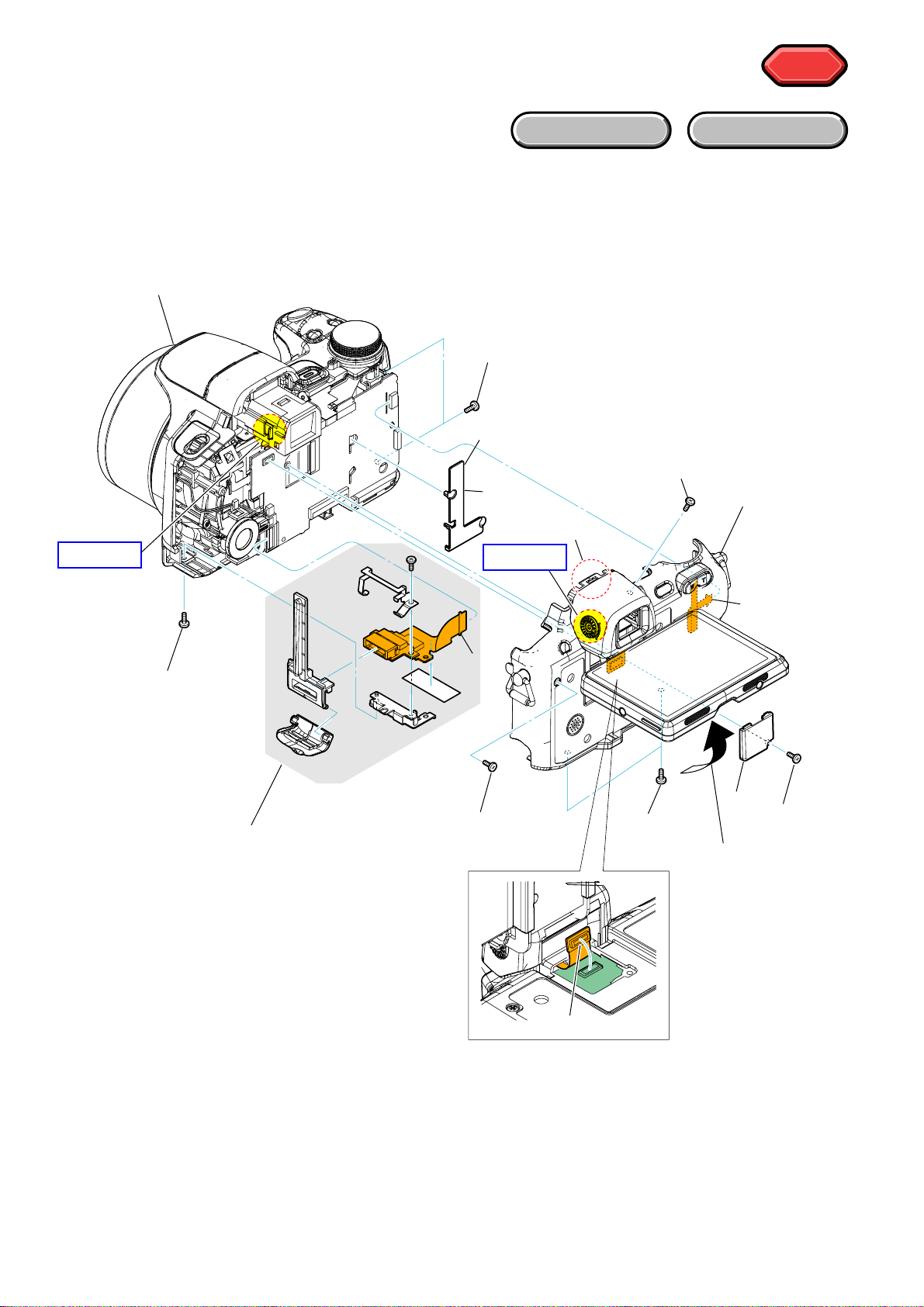
2-2-5. CABINET (REAR) SECTION
EXPLODED VIEW
Follow the disassembly in the numerical order given.
1 SW-532 Board (1-1 to 1-5)
2 LCD Section (2-1 to 2-4)
1-1 (#5)
1
SW-532 Board
HARDWARE LIST
1-5
1-3
1-2
2-1
(#12)
1-4
(Claw)
2-2
(#12)
HELP09
2-3
(Claw)
2-4
2
LCD Section
(See Page 2-8)
DSC-H50_L2
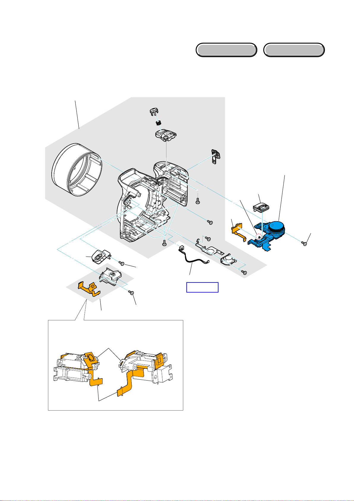
How to diassemble the Hinge Part
Hinge Part
Pass it through this point of
Cabinet (Rear).
2-7
Pass it through this point of
Cabinet (Rear).
Hinge Part
HELP10
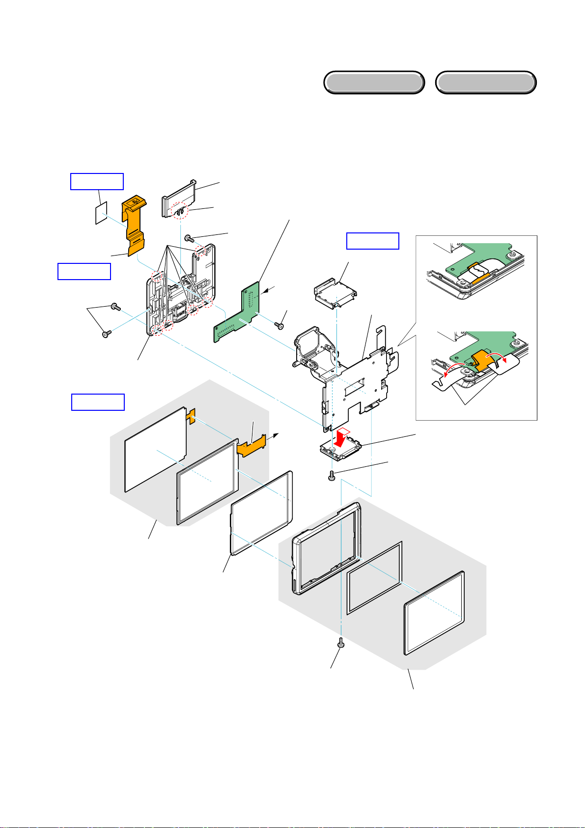
2-2-6. LCD SECTION
EXPLODED VIEW
Follow the disassembly in the numerical order given.
1 P Cabinet (C) Assy (470) (1-1 to 1-9)
2 CK-198 Board (2-1 to 2-8)
HARDWARE LIST
HELP12
1-9
HELP11
1-7
(#1/#14)
1
P Cabinet (C)
Assy (470)
HELP11
1-8
(Claw)
1-5
1-4 (Claw)
1-6
(#1/#14)
2-2
2
CK-198 Board
A
2-7
(#14)
A
HELP11
1-3
2-8
2-1
1-2
1-1
(#1/#14)
DSC-H50_L2
2-6
2-5
2-3
(#1/#14)
2-4
2-8E
HELP
Sheet attachment positions and procedures of processing the flexible boards/harnesses are shown.
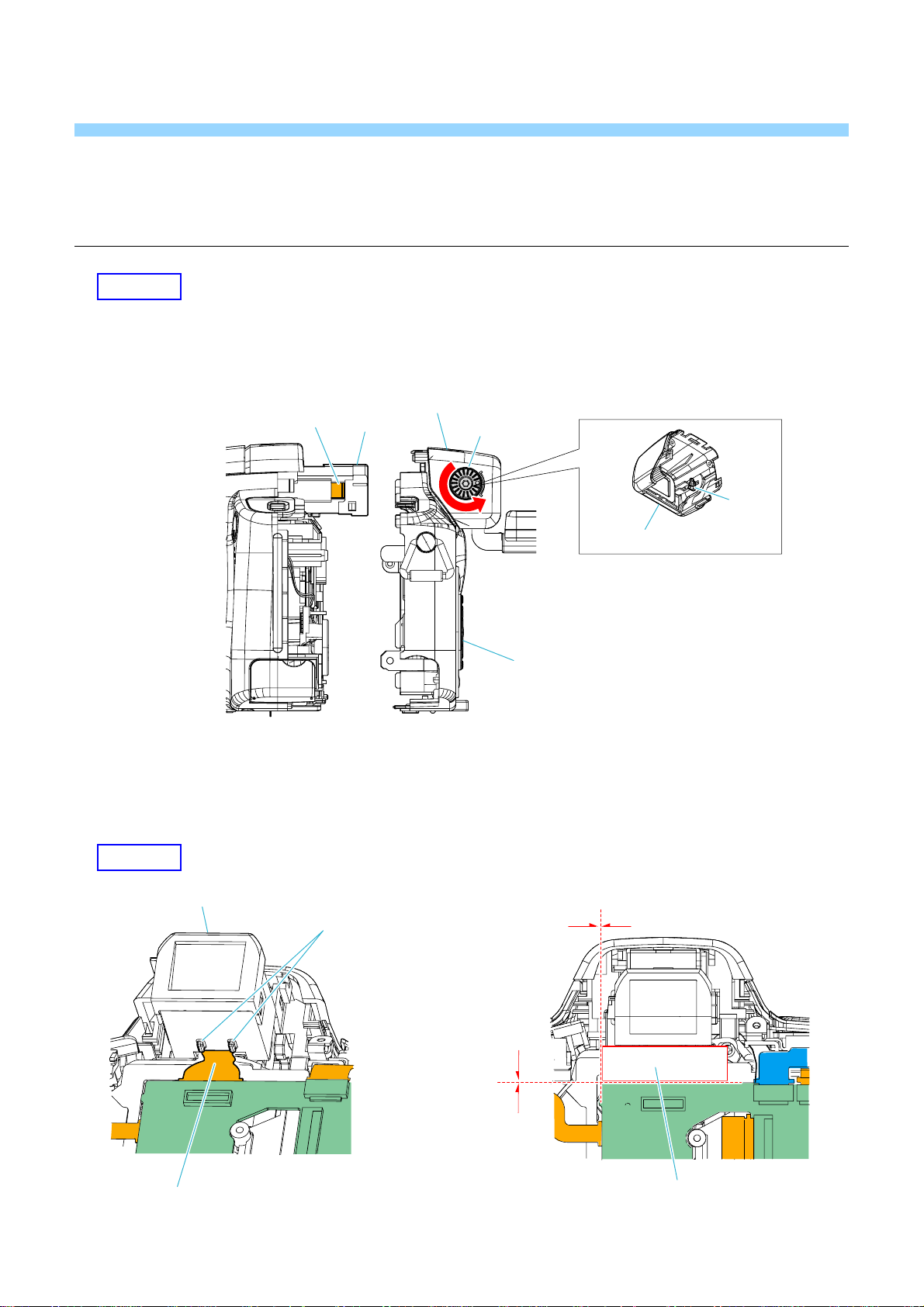
HELP01
In case of assembling the cabinet (rear) assy, attach it after turning fully counterclockwise the visibility dial.
Be careful about the lever inside of the eye cup assy doesn't go over the EVF lever.
Lever
Eye Cup Assy
EVF
Visibility Dial
Lever
Eye Cup Assy
Cabinet (Rear) Assy
HELP02
Bend the flexible board to
the main body side at claws.
DSC-H50_L2
EVF
0 to 1mm
Claws
0 to 1mm
Tape (A)
HELP
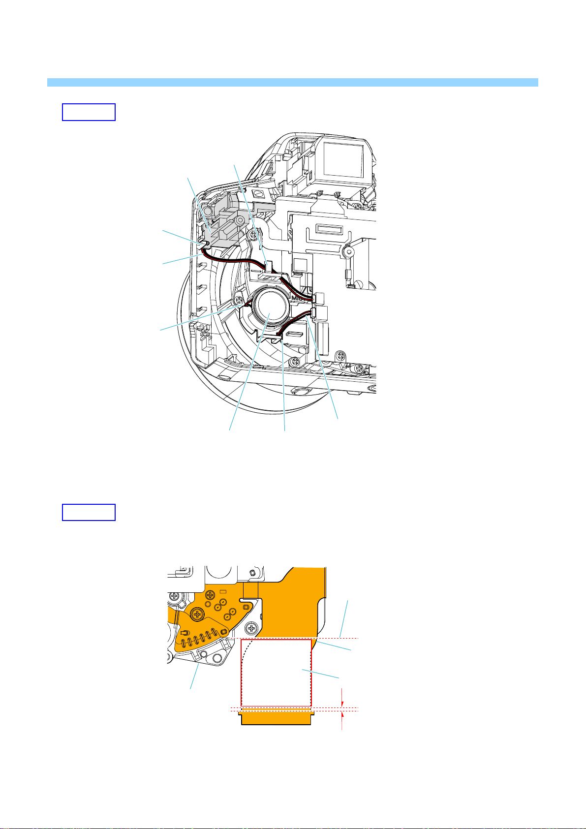
HELP03
Microphone Holder
Harness
(Microphone Unit)
Lib
Lib
Cutout
HELP04
Loudspeaker (1.3cm)
Lens Block Assy
Cutout
Harness
(Loudspeaker (1.3cm))
Crease left point
Attach covering the flexible board.
Lens (Radiation) Sheet
0 to 1mm
DSC-H50_L2
HELP
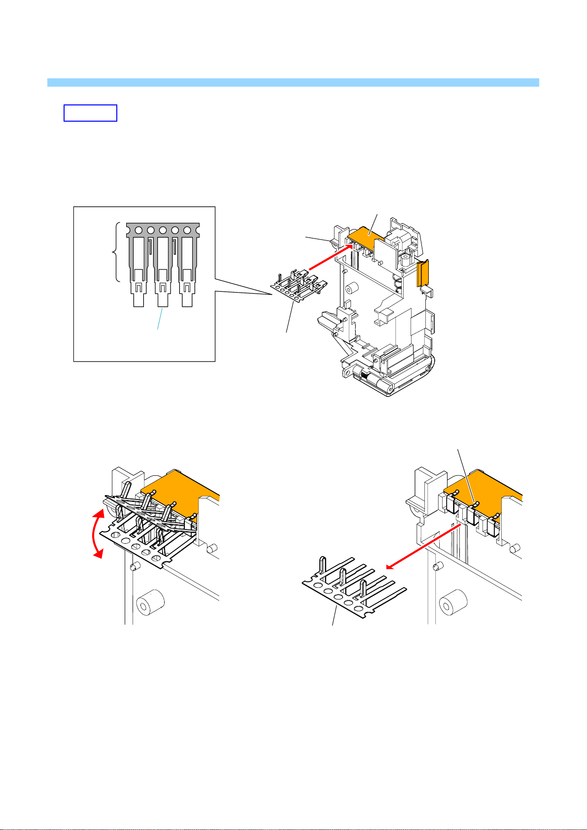
HELP05
INSTALLATION METHOD OF THE BATTERY TERMINAL BOARD
1 Insert the battery terminal board into a slit in the BT holder to install.
The battery terminal holder are attached with the notch for installation.
DC-111 Flexible Board
BT holder
Notch
Battery T erminal
Board
2 Fold the notch 3 or 4 times repeatedly to break.
Battery T erminal
Board
Battery T erminal Board
DSC-H50_L2
Notch
HELP
 Loading...