

Sony RDR-GX350, RDR-HX650, RMT-D246P, RMT-D247P, RMT-D245P Service Manual
...
Q
Q
3
7
6
3
1
5
1
5
0
RDR-GX350/HX650/
HX750/HX950
RMT-D245P/D246P/D247P
8
9
2
4
9
8
2
9
9
SERVICE MANUAL
Ver. 1.2 2007.10
Revised-2
TEL 13942296513 QQ 376315150 892498299
Photo: RDR-HX750
RMT-D247P
(HX750/HX950) (HX750/HX950)
System
Laser: Semiconductor laser
Channel coverage:
PAL/SECAM (B/G, D/K, I, L)
VHF: E2 to E12, R1 to R12, F2 to F10,
Italian A to H, Ireland A to J, South
TEL
Africa 4 to 11, 13
13942296513
UHF: E21 to E69, R21 to R69, B21 to
B69, F21 to F69
CATV: S01 to S05, S1 to S20, France
B to Q
HYPER: S21 to S41
The above channel coverage me rely ensures
the channel reception within these ranges. It
does not guarantee the ability to receive
signals in all circumstances. For details, see
“Receivable chan nels”.
Video reception: Frequency synthesizer
system
Audio reception: Split carrier system
Aerial out: 75-ohm asymmetrical aerial
socket
Timer: Clock: Quartz locked/Timer
indication: 24-hour cycle (digit al )/
Power back-up duration: 1 hour
Video recording format: MPEG-2,
MPEG-1
Audio recording format/applicable
bit rate: Dolby Digital 2 ch
256 kbps/128 kbps (in EP, SLP, and
SEP mode), PCM
(GX350/HX650)
SPECIFICATIONS
Inputs and outputs
LINE 2 OUT
(AUDIO): Phono jack/2 Vrms/10 kilohms
(VIDEO): Phono jack/1.0 Vp-p
(S VIDEO): 4-pin mini DIN/Y: 1.0 Vp-p,
C: 0.3 Vp-p (PAL)
LINE 2 IN
(AUDIO): Phono jack/2 Vrms/more than
22 kilohms
(VIDEO): Phono jack/1.0 Vp-p
(S VIDEO): 4-pin mini DIN/Y: 1.0 Vp-p,
C: 0.3 Vp-p (PAL)
LINE 3 – TV: 21-pin
CVBS OUT
S-Video/RGB OUT (upstream)
LINE 1/DECODER: 21-pin
CVBS IN/OUT
S-Video/RGB IN
Decoder
DV IN:
RDR-HX750/HX950:
4-pin/i.LINK S10 0
DIGITAL OUT (COAXIAL): Ph ono jack/
0.5 Vp-p/75 ohms
COMPONENT VIDEO OUT
(Y, P
Phono jack/Y: 1.0 Vp-p,
B/CB
P
G-LINK:
RDR-HX750/HX950:
mini jack
HDMI OUT: HDMI 19-pin-Standard
Connector
Q
Q
B/CB
, PR/CR):
: 0.7 Vp-p, PR/CR: 0.7 Vp-p
3
7
6
3
1
AEP Model
RDR-GX350/HX650/HX750/HX950
UK Model
RDR-GX350/HX750
Russian Model
RDR-GX350/HX750/HX950
USB:
RDR-HX750/HX950:
USB jack Type A (For connecting
digital still camera, Memory card
reader and USB memory)
USB jack Type B (For connecting
PictBridge-compatible printers)
9
8
0
5
1
5
General
Power requirements: 220-240 V AC,
50/60 Hz
Power consumption:
RDR-GX350: 22 W
RDR-HX650: 40 W
RDR-HX750/HX950: 44 W
Dimensions (approx.):
4
30 × 66.5 × 286 mm (width/height/
depth) incl. projecting parts
Hard disk drive capacity:
RDR-HX650/HX750: 160 GB
RDR-HX9
Mass (approx.):
RDR-GX350 : 3.6 kg
RDR-HX650/HX750/HX950: 4.4 kg
Operating temperature: 5°C to 35°C
Operating humidity: 25% to 80 %
Supplied accessories:
Mains lead (1)
Aerial cable (1)
Remote commander (remote) (1)
RDR-HX750: AEP, UK/HX950: AEP, UK:
Set top box controller (1)
R6 (size AA) batteries (2)
Specifications and design are subject to
change without notice.
9
4
2
50: 250 GB
8
2
9
TEL 13942296513 QQ 376315150 892498299
9
w
w
w
.
xia
o
y
u
1
6
3
.
c
o
DVD RECORDER
m
WARNING!!
7
Q
Q
WHEN SERVICING, DO NOT APPROACH THE LASER EXIT WITH
THE EYE TOO CLOSELY. IN CASE IT IS NECESSARY TO
CONFIRM LASER BEAM EMISSION, BE SURE TO OBSERVE
FROM A DISTANCE OF MORE THAN 25 cm FROM THE SURFACE
OF THE OBJECTIVE LENS ON THE OPTICAL PICK-UP BLOCK.
CAUTION:
The use of optical instrument with this product will increase eye
hazard.
CAUTION
Use of controls or adjustments or performance of procedures
other than those specified herein may result in hazardous radiation
exposure.
TEL 13942296513 QQ 376315150 892498299
COMPONENTS IDENTIFIED BY MARK 0 OR DOTTED LINE WITH
MARK 0 ON THE SCHEMATIC DIAGRAMS AND IN THE PARTS
LIST ARE CRITICAL TO SAFE OPERATION. REPLACE THESE
COMPONENTS WITH SONY PARTS WHOSE PART NUMBERS
APPEAR AS SHOWN IN THIS MANUAL OR IN SUPPLEMENTS
PUBLISHED BY SONY.
3
SAFETY-RELATED COMPONENT WARNING!!
6
3
1
5
1
5
Unleaded solder
Boards requiring use of unleaded solder are printed with the lead-
0
free mark (LF) indicating the solder contains no lead.
(Caution: Some printed circuit boards may not come printed with
the lead free mark due to their particular size.)
: LEAD FREE MARK
Unleaded solder has the following characteristics.
• Unleaded solder melts at a temperature about 40°C higher than
ordinary solder.
Ordinary soldering irons can be used but the iron tip has to be
applied to the solder joint for a slightly longer time.
Soldering irons using a temperature regulator should be set to
about 350°C.
Caution: The printed pattern (copper foil) may peel away if the
heated tip is applied for too long, so be careful!
• Strong viscosity
Unleaded solder is more viscous (sticky , less prone to flow) than
ordinary solder so use caution not to let solder bridges occur such
as on IC pins, etc.
• Usable with ordinary solder
It is best to use only unleaded solder but unleaded solder may
also be added to ordinary solder.
Special Component Notice
The components identified by mark 9 contain confidential
information.
Strictly follow the instructions whenever the components are repaired
and/or replaced.
8
9
2
4
9
8
2
9
9
TEL 13942296513 QQ 376315150 892498299
TEL
1. Check the area of your repair for unsoldered or poorly-soldered
connections. Check the entire board surface for solder splashes
and bridges.
2. Check the interboard wiring to ensure that no wires are
"pinched" or contact high-wattage resistors.
3. Look for unauthorized replacement parts, particularly
transistors, that were installed during a previous repair . Point
them out to the customer and recommend their replacement.
13942296513
After correcting the original service problem, perform the following
safety checks before releasing the set to the customer.
SAFETY CHECK-OUT
8
9
4
2
9
8
0
5
1
5
1
3
6
7
3
Q
Q
4. Look for parts which, through functioning, show obvious signs
of deterioration. Point them out to the customer and
recommend their replacement.
5. Check the B+ voltage to see it is at the values specified.
6. Flexible Circuit Board Repairing
• Keep the temperature of the soldering iron around 270˚C
during repairing.
• Do not touch the soldering iron on the same conductor of the
circuit board (within 3 times).
• Be careful not to apply force on the conductor when soldering
or unsoldering.
2
9
9
w
w
w
.
xia
o
y
u
1
6
3
— 2 —
.
c
o
m

TABLE OF CONTENTS
SERVICE NOTE
Q
TEL 13942296513 QQ 376315150 892498299
1. DISK REMOVAL PROCEDURE IF THE TRAY
Q
2. BOARD CONNECTION, SER VICE REMOTE
3. MODEL NAME SETTING METHOD WHEN ENGINE
4. HOW TO DIAGNOSE HDD FAILURE ···························· 7
4-1. Defective HDD ··································································· 7
4-2. HDD Recognition status····················································· 7
4-3. Display [E01] on FLD with unrecognized HDD················ 8
4-4. Display [E02] on FLD ························································ 9
4-5. When playing a video, MP3, or JPG, the contents freeze ·· 9
4-6. Factory Check··································································· 10
4-7. Final Check······································································· 10
5. CHANGED POINTS OF SER VICE MANUAL
1. GENERAL
WARNING ············································································1-1
Precautions·············································································1-1
Quick Guide to Disc Types ····················································1-1
Hookups and Settings ································································1-2
Hooking Up the Recorder ······················································1-2
Step 1: Connecting the Aerial Cable and Set Top Box Control-
Step 2: Connecting the Video Cords/HDMI Cord ·················1-3
Step 3: Connecting the Audio Cords/HDMI Cord·················1-4
Step 4: Connecting the Mains Lead·······································1-4
Step 5: Preparing the Remote ················································1-4
Step 6: Easy Setup ·································································1-5
Connecting a VCR or Similar Device ··································· 1-6
Connecting an External Decoder ···········································1-6
TEL
Eight Basic Operations
1. Inserting a Disc ··································································1-7
2. Recording a Programme ····················································1-7
3. Playing the Recorded Programme (Title List)···················1-7
4. Displaying the Playing Time and Play Information ··········1-8
5. Changing the Name of a Recorded Programme ················1-8
6. Labelling and Protecting a Disc·········································1-9
7. Playing the Disc on Other DVD Equipment (Finalise) ·····1-9
8. Reformatting a Disc ·························································1-10
Guide Plus+ ·············································································1-10
Introduction to the GUIDE Plus+ System ···························1-10
Watching TV Using the GUIDE Plus+ System ··················· 1-10
Searching for a Programme Using the GUIDE Plus+
Listing Up Your Favourite Programme Information
Making Changes to the GUIDE Plus+ System····················1-11
Timer Recording······································································ 1-12
Before Recording·································································1-12
Timer Recording (GUIDE Plus+/Manual) ··························1-12
Checking/Changing/Cancelling Timer Settings ··················1-13
Recording from Connected Equipment ·······························1-14
Playback ·················································································· 1-14
Playing the Recorded Programme/DVD ·····························1-14
Pausing a TV Broadcast (TV Pause/Pause Live TV) ··········1-16
Playing from the Beginning of the Programme You Are
Playing a Previous Recording While Making Another
Searching for a Time/Title/Chapter/Track, etc ····················1-16
Erasing and Editing ·································································1-17
w
w
Before Editing······································································1-17
Erasing and Editing a Title ··················································1-17
7
3
CANNOT BE EJECTED (FORCED EJECTION) ············ 5
CONTROLLER·································································· 5
IS REPLACED ··································································· 6
Revised-2·········································································· 12
ler ·······················································································1-2
6
13942296513
— Getting to Know Your DVD Recorder ·······················1-7
System··············································································1-11
(My TV) ···········································································1-11
Recording (Chase Play) ···················································1-16
(Simultaneous Rec and Play) ···········································1-16
w
.
1
3
xia
5
o
1
y
5
u
0
Q
Q
1
Erasing and Editing a Chapter ·············································1-18
Creating and Editing a Playlist ············································1-18
Dubbing (HDD y DVD) ······················································1-19
Before Dubbing ···································································1-19
HDD/DVD Dubbing ····························································1-19
Dubbing Using Dubbing List ··············································1-19
Making a Backup Disc (DVD Backup) ······························· 1-20
DV Camcorder Dubbing··························································1-20
Before DV Camcorder Dubbing ··········································1-20
Dubbing an Entire DV Format Tape
Dubbing Selected Scenes (Manual Dubbing)······················1-21
Playing from a DV Camcorder ············································1-21
Audio Tracks ···········································································1-21
Playing Audio Tracks from CD/DVD ·································1-21
Searching for an Audio Track ··············································1-22
About Jukebox ····································································· 1-22
Preparing for Using Jukebox ···············································1-22
Playing Audio Tracks Using Jukebox/USB Device ············1-23
Managing Audio Tracks on the Music Jukebox ··················1-23
JPEG Image Files ····································································1-24
About the “Photo Album” Function ····································1-24
Preparing for Using the “Photo Album” Function···············1-24
Using the “Photo Album” List·············································1-25
Managing JPEG Image Files on the HDD···························1-25
Printing JPEG Image Files ··················································1-26
Settings and Adjustments ························································1-26
Disc Settings (Disc Setup) ···················································1-26
Recording Settings (Basic) ··················································1-26
Aerial Reception Settings (Tuner) ······································· 1-27
Video Settings (Video In/Out) ············································· 1-28
Audio Input Settings (Audio In) ··········································1-28
Audio Output Settings (Audio Out)·····································1-28
7
3
Language Settings (Language) ············································1-29
Recording Settings (Recording) ·········································· 1-29
Playback Settings (Playback) ·············································· 1-30
HDMI Settings (HDMI Output) ··········································1-30
Other Settings (Options) ······················································1-31
Additional Information ····························································1-31
Troubleshooting ···································································1-31
Resetting the Recorder························································· 1-33
Notes About This Recorder ·················································1-33
Specifications·······································································1-34
Notes on MP3 Audio Tracks, JPEG Image Files, and DivX
About i.LINK·······································································1-34
Guide to Parts and Controls ·················································1-35
Language Code List ·····························································1-36
Country/Area Code ······························································1-36
2. DISASSEMBLY
2-1. UPPER CASE ·································································2-2
2-2. TRAY COVER ASSEMBLY ··········································2-2
2-3. FRONT PANEL SECTION·············································2-3
2-4 FR-274 BOARD, FL-178 BOARD ·································2-3
2-5. DVD DRIVE ···································································2-4
2-6. DC FAN···········································································2-4
2-7. HARD DISK (Except GX350)········································2-5
2-8. AV-114/118 BOARD ·······················································2-5
2-9. VDC-001 BOARD (Type AS, BS only) ··························2-6
2-10. POWER SUPPLY BLOCK ·············································2-6
2-11. CIRCUIT BOARDS LOCATION ···································2-7
3. BLOCK DIAGRAMS
3-1. OVERALL BLOCK DIAGRAM ····································3-1
6
3
3-2. AV-114/118 BLOCK DIAGRAM ···································3-3
3-3. RD-065 BLOCK DIAGRAM··········································3-5
4
2
9
8
(DV One Touch Dubbing) ················································1-21
0
5
1
5
1
3
6
Video Files ·······································································1-34
.
c
o
9
9
8
m
2
8
4
2
9
8
9
2
9
9
9
TEL 13942296513 QQ 376315150 892498299
— 3 —

3-4. FR-274, FL-178, VDC-001 BLOCK DIAGRAM ··········3-7
3-5. POWER BLOCK DIAGRAM ········································3-9
Q
Q
4. SCHEMATIC DIAGRAMS AND
PRINTED WIRING BOARDS
4-1. FRAME SCHEMATIC DIAGRAM ································4-1
4-2. SCHEMA TIC DIAGRAMS ············································4-3
WAVEFORMS ································································ 4-4
• AV-114/118 (1/5) (IT CONTROLLER, IR)
• AV-114 (2/5) (POWER/FAN CONT.)
• AV-118 (2/5) (POWER/FAN CONT.)
• AV-114/118 (3/5) (VIDEO/AUDIO)
TEL 13942296513 QQ 376315150 892498299
• AV-114/118 (4/5) (EURO)
• AV-114/118 (5/5) (TUNER)
• VDC-001 (VIDEO ENCODER)
• FR-274 (FL DRIVER, LINE 2 IN, FUNCTION SW)
• FL-178 (DV, USB, REMOCON RECEIVER,
POWER SW)
• RD-065 (1/7) (POWER BLOCK)
• RD-065 (2/7) (EMMA BLOCK)
• RD-065 (3/7) (VIDEO/AUDIO BLOCK)
TEL
• RD-065 (4/7) (MEMORY BLOCK)
• RD-065 (5/7) (SATA/IDE IF)
• RD-065 (6/7) (HDMI/DV/USB BLOCK)
• RD-065 (7/7) (DVD DRIVE)
• SWITCHING REGULATOR (SRV-2058EK)
4-3. PRINTED WIRING BOARDS ·····································4-39
• VDC-001 (VIDEO ENCODER)
• FR-274 (FL DRIVER, LINE 2 IN, FUNCTION SW)
• AV-114 (IT CONTROLLER, IR, POWER/FAN CONT.,
VIDEO/AUDIO, EURO, TUNER)
• AV-118 (IT CONTROLLER, IR, POWER/FAN CONT.,
VIDEO/AUDIO, EURO, TUNER)
• RD-065 (POWER BLOCK, EMMA BLOCK, VIDEO/
AUDIO BLOCK, MEMORY BLOCK, SATA/IDE IF,
HDMI/DV/USB BLOCK, DVD DRIVE)
• FL-178 (DV, USB, REMOCON RECEIVER,
POWER SW)
7
3
SCHEMATIC DIAGRAM ······························4-5
SCHEMATIC DIAGRAM ······························4-7
SCHEMATIC DIAGRAM ······························4-9
SCHEMATIC DIAGRAM ····························4-11
SCHEMATIC DIAGRAM ····························4-13
SCHEMATIC DIAGRAM ····························4-15
SCHEMATIC DIAGRAM ····························4-17
SCHEMATIC DIAGRAM ····························4-19
SCHEMATIC DIAGRAM ····························4-21
SCHEMATIC DIAGRAM ····························4-23
SCHEMATIC DIAGRAM ····························4-25
SCHEMATIC DIAGRAM ····························4-27
13942296513
SCHEMATIC DIAGRAM ····························4-29
SCHEMATIC DIAGRAM ····························4-31
SCHEMATIC DIAGRAM ····························4-33
SCHEMATIC DIAGRAM ····························4-35
SCHEMATIC DIAGRAM ····························4-37
PRINTED WIRING BOARD ·······················4-39
PRINTED WIRING BOARD ·······················4-41
PRINTED WIRING BOARD ·······················4-43
PRINTED WIRING BOARD ·······················4-47
PRINTED WIRING BOARD ·······················4-51
PRINTED WIRING BOARD ·······················4-55
6
3
1
5
1
5
5-2. AV ENCODER/DECODER IC
0
(IC1001:MC10050F1-105/505-LU1-A
(RD-65 BOARD)) ···························································5-3
6. SERVICE MODE
6-1. SERVICE MODE MAP ····················································· 2
6-2. Diagnostic Mode ································································ 3
6-2-1.Model Setting ····································································· 3
6-2-2.Service Mode······································································ 4
6-2-3.Version Information and Other Information (First screen) 4
6-2-4.RF Level Simplified Diagnosis (Subscreen1) ···················· 5
6-2-5.HDD Information for the HDD return sheet
(Simplified measurement mode) ········································ 6
6-2-6.Cautions for handling the HDD·········································· 7
6-2-7.HDD Error Logging ··························································· 9
6-2-8.AT A/ATAPI History - ERR ············································· 10
6-2-9.How to confirm HDD Access Flow·································· 10
6-2-10. ATA/ATAPI Debugging Screen Second Screen and LD
Deterioration Judgment (for writer) ······························· 11
6-2-11. History of VR Recording-related Errors························ 13
6-2-12. DV Service Mode ·························································· 17
6-2-13. EPG Service Mode························································· 19
6-2-14. Aging Mode ··································································· 21
6-2-15. HDD Check Mode ························································· 22
6-3. Setup Related Menu ························································· 23
6-3-1.Firmware Downloading ···················································· 23
6-3-2.Area-Specific Channel Setting ········································· 23
6-3-3.OSD Filter Setting ···························································· 24
7. ADJUSTMENTS
7-1. Video System Adjustment ···············································7-1
8. REP AIR PARTS LIST
Q
Q
8-1. EXPLODED VIEWS
8-1-1.OVERALL SECTION·····················································8-1
8-1-2.CHASSIS SECTION·······················································8-2
8-2. ELECTRICAL PARTS LIST ··········································8-3
3
7
8
6
3
9
1
5
2
1
5
4
0
9
8
9
8
2
4
2
9
8
9
2
9
9
TEL 13942296513 QQ 376315150 892498299
9
5. IC PIN FUNCTION DESCRIPTION
5-1. IT CONTROL IC
(IC101:LC87F06J2A-F58W3-E (AV-114 BOARD)) ······5-1
w
w
w
.
xia
o
y
u
1
6
3
— 4 —
.
c
o
m
)
Q
SERVICE NOTE
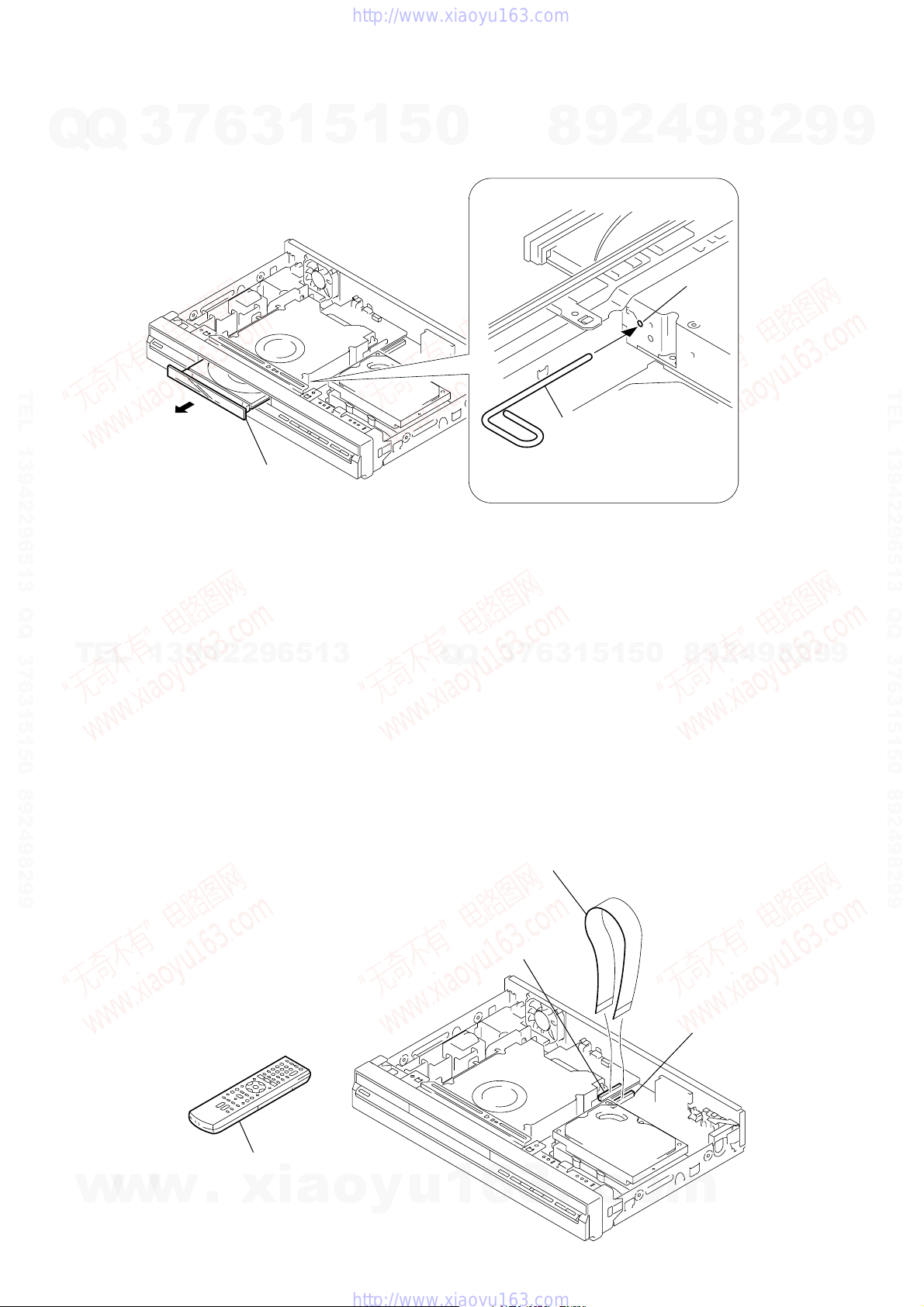
1. DISK REMOVAL PROCEDURE IF THE TRAY CANNOT BE EJECTED (FORCED EJECTION)
1. Remove the upper case.
Q
2. Insert the stiff wire in the hole and eject the tray.
3
7
6
3
1
5
1
5
0
8
9
2
4
9
Hole
8
2
9
9
TEL 13942296513 QQ 376315150 892498299
Open the tray
NOTES DURING THE FORCED EJECTION
1. If the forced ejection is executed while a blank disc media (DVD±RW , ±R) exists on the tray
• Insert a DVD-ROM (DVD test disc, DVD software available on the market, or the like) in the tray and then close the tray.
Note1: If you close the tray while it is empty, ejection of the tray becomes impossible.
Note2: If you close the tray with a CD disc inserted in it, the CD can be ejected. However, if you close the tray while it is empty, there can be a case that
ejection of the tray becomes impossible.
Note3: Even if you replace the DVD drive unit while the tray remains under the state as described above, the situation cannot be improved.
TEL
13942296513
2. If the tray cannot be ejected while the disc is not inserted
• Execute the forced ejection.
• Insert a DVD-ROM (DVD test disc, DVD software available on the market, or the like) on the tray and try to close the tray.
(There are cases that it recovers the trouble.)
3. Contents of forcedly ejected blank disc media (D VD±RW, ±R) can be damaged. (There can be a case that initialization is also impossible.)
2. BOARD CONNECTION, SERVICE REMOTE CONTROLLER
Q
Q
3
7
6
3
1
The stiff wire
1
5
1
5
0
8
9
2
4
9
8
2
9
TEL 13942296513 QQ 376315150 892498299
9
w
w
w
RD-065 board : CN2301(40core)
SERVICE REMOTE CONTROLLER
(J-6090-203-A)
.
xia
o
y
u
Extension cable
(J-6090-201-A)
1
6
— 5 —
3
.
c
AV-114 board : CN101(40core
o
m
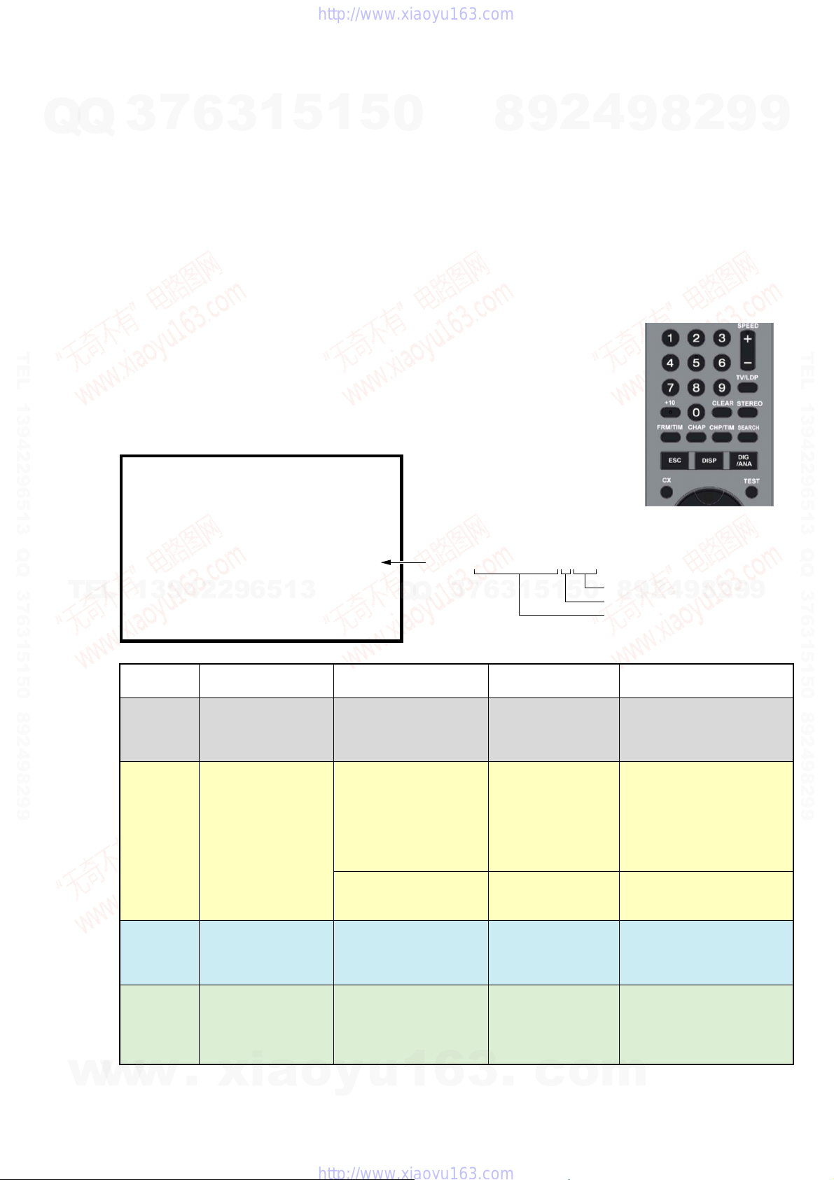
3. MODEL NAME SETTING METHOD WHEN ENGINE IS REPLACED
Required equipment:
Q
Q
• Remote controller (RMT-D245P/D246P/D247P)
• Service remote controller (J-6090-203-A)
• Monitor
Model name delete method
1. Turn the main POWER ON.
2. Press the following buttons on the service remote controller in this order.:
“ESC” k “CHAP” k “1”
* Confirm that the above operation is performed in the state that the screen has exited all settings such as “Home Menu” or “Simple
Setting”.
3. Turn the main POWER OFF.
4. Turn the main POWER ON. (The screen as shown in Fig. 1 appears.)
5. Select “2” on the screen by using the service remote controller.
TEL 13942296513 QQ 376315150 892498299
* If “1” is selected on the screen, the machine will not work at all. Be sure to select “2”.
6. Find out the tentative model name from the Correspondence Table (Table 1) for the client machine. Then, enter the 4-digit “Input No.”
on the screen using the service remote controller.
7. The model name setting method is complete. (Screen disappears.)
* Upon completion of the model name setting, be sure to press both “ENTER” and “3” simultaneously on the service remote controller
without fail. It sets the remote control code “3”.
3
7
6
3
1
5
1
5
0
8
9
2
4
9
8
2
9
9
TEL 13942296513 QQ 376315150 892498299
TEL
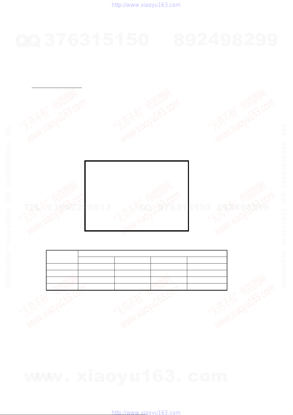
Fig.1 S-company/P-company selection
[Recorder's Model Setting]
Input the number using the remote for Service
>?
Input No. Manufacturer
[ 1 : P ]
13942296513
Table1 Correspondence table between tentative model name and final product name
Model name
RDR-GX350 MRX-1600/EC1 MRX-1600/EC2 — MRX-1600/CEK
RDR-HX650 MRX-1620/EC1 MRX-1620/EC2 MRX-1620/EC1 —
RDR-HX750 MRX-1635/EC1 MRX-1630/EC2 — MRX-1635/CEK
RDR-HX950 MRX-1655/EC1 MRX-1650/EC2 ——
[2:S ]
Tentative model name
AEP1 AEP2 AEP3 UK
Q
Q
3
7
6
3
1
5
1
5
0
8
9
2
4
9
8
2
9
9
w
w
w
.
xia
o
y
u
1
6
3
— 6 —
.
c
o
m
4. HOW TO DIAGNOSE HDD FAILURE
7
Q
Q
TEL 13942296513 QQ 376315150 892498299
3
4-1. Defective HDD
There are four symptoms of defects in the HDD.
1. “E01” is displayed on the FLD.
(The HDD is not recognized or is not authorized.)
2. “E02” is displayed on the FLD.
3. When playing a video, MP3, or JPG, contents freeze.
4. Irregular noises from the HDD
4-2. HDD Recognition status
How to enter Recognition status and sub screen mode.
• While the GUI screen is not displayed, use the service remote controller and press “ESC” key followed by “DISP” key.
• While the first screen is displayed, press “DIG/ANA” key repeatedly until the desired subscreen is displayed.
The subscreens change.
6
3
1
5
1
5
0
4
2
9
8
Service remote controller
(Part code: J-6090-203-A)
9
8
2
9
9
TEL 13942296513 QQ 376315150 892498299
TEL
MRX-1635/EC1 VERSION : 1.01
SYSCON
TUNERCON
PIC SERIAL
HDD INT
13942296513
DEVICE : E2R-FEx1.0 FLASH : 64M
REGION : 2 C : 0000400259
HDCP : 0000400259
FL Display
REPAIR
E01
E02
Normal
: RELEASE 104
Rev. 1. 5895
: 1.178 OK
: DVD-RW DVR-L12X OK
DRIVE
1.00 OK
: 000800004940
: WDC WD2500AAJS 9 250
OS Display
“Repaining the HDD”.
r
“HDD repair is
complete”.
An error occurred.
Please consult your
nearest Sony dealer.
Note that contents on
the HDD may be
erased when servicing
this unit.
The Hard Disk Drive
info is incorrect.
Use the Disk Setup
menu to reformat.
Failure to physically
identify the HDD (no
connection, defective
HDD, interface error).
Physical identification of
HDD possible, but not
identified
Physical identification of
HDD possible, HDD
identified, but failure in
logical formatting.
Physical identification of
HDD possible, HDD
identified, and correct
logical formatting (HDD
correctly identified).
• Details on HDD data are described below:
HDD : WDC1023456 # 160
3
Q
Q
HDD identification
conditions
5
1
3
6
7
Details on HDD data
are described below.
Blank space
WDC 10234564 # 160
WDC 10234564 ! 160
WDC 10234564 160
1
5
Capacity of the HDD (unit: Gbytes)
2
9
8
0
HDD identification error indication
HDD model name
Check the connection to the
SATA cable and power cable.
Replace the SATA cable or
power cable.
Replace the HDD.
Replace the FE or part in the
SATA/ATA communication.
“#” indicates that the HDD is
not recognized.
“!” indicates an HDD
authorization error. Initialize
the HDD.
9
4
Remarks
8
2
9
9
w
w
w
.
xia
o
y
u
1
6
3
— 7 —
.
c
o
m
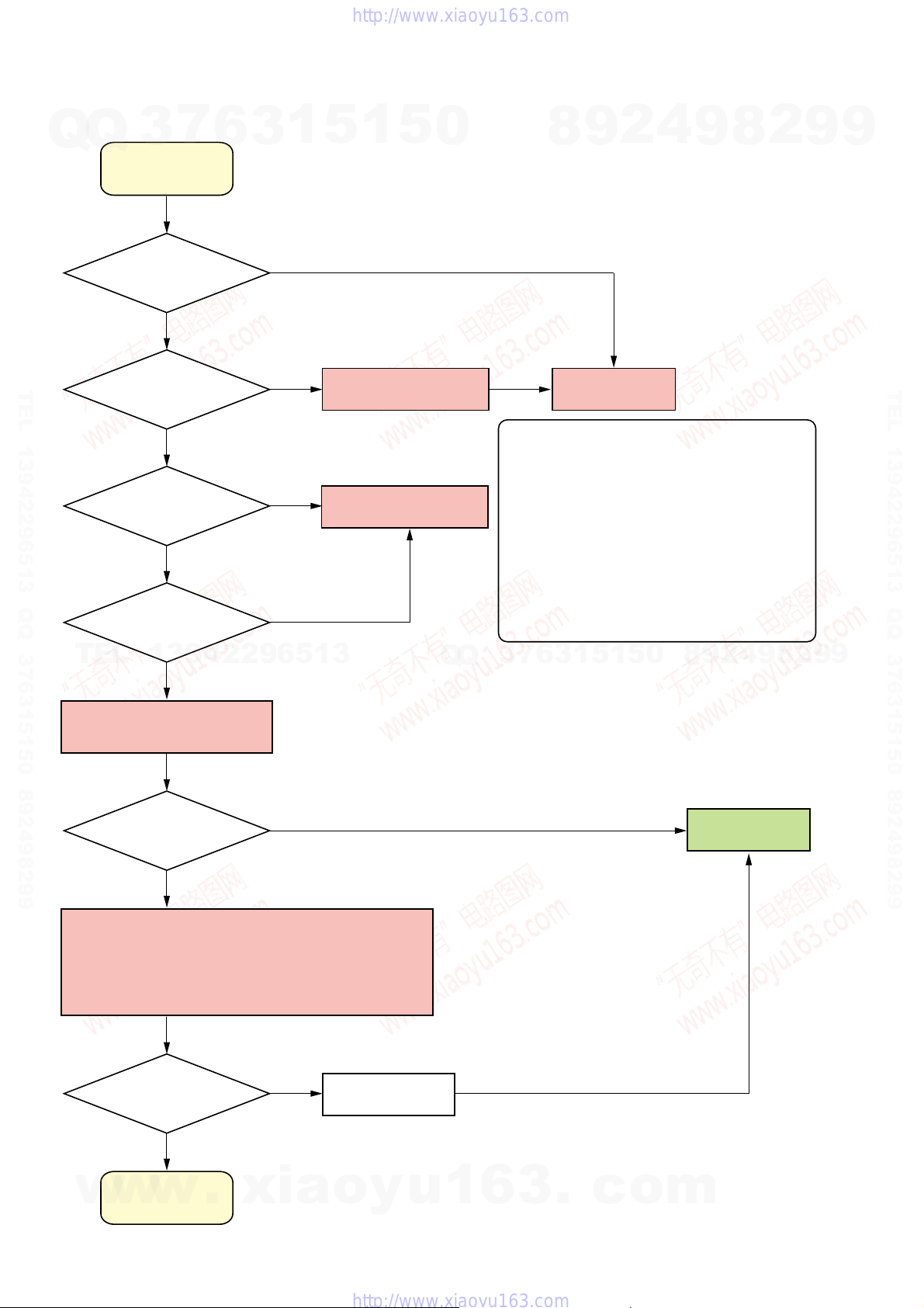
4-3. Display [E01] on FLD with unrecognized HDD
Q
Q
3
E01
7
6
3
1
5
1
5
0
8
9
2
4
9
8
2
9
9
Is the HDD free from
abnormal noises?
YES
TEL 13942296513 QQ 376315150 892498299
Is not “#” displayed?
YES
Reconnect the SATA
cable. Does the problem
still occur?
YES
Replace the SATA cable.
Does the problem
TEL
still occur?
13942296513
YES
NO
NO
NO
NO
Unauthorized HDD
Replace the SATA Cable
Q
Q
Note: Write down the HDD information on the HDD
7
3
Refer to “Note”.
0
*
8
9
2
4
9
8
Replace the HDD
return sheet before replacing the HDD.
Note the information on pages 6-6, 6-7, 6-9,
and 6-10 of Chapter 6, “SERVICE MODE”.
For information about replacing the HDD, see
page 2-5 of Chapter 2, “DISASSEMBLY”.
After replacing the HDD, perform
“Factory Check” on “SERVICE NOTE”, page 10.
When performing “Factory Check”, the data
saved to the HDD by the customer is erased.
Obtain customer consent before performing
“Factory Check”.
5
1
5
1
3
6
2
9
TEL 13942296513 QQ 376315150 892498299
9
Replace the HDD with a new
one and perform Factory Check.
Does the problem
still occur?
YES
There may be a problem with the Engine.
Therefore, put the original HDD back in the unit.
Then, follow the procedure to replace the Engine.
After replacing the Engine, perform “Setting the Model Name”
on “Service Note”, page 6.
Does the problem
still occur?
YES
Refer to “Note”.
*
NO
NO
Final check
Note: Performing “Final Check” will not erase the HDD data.
END
Note: Write down the HDD information on the HDD
return sheet before replacing the Engine.
For information about replacing the Engine,
see page 2-4 of Chapter 2, “DISASSEMBLY”.
When performing “Factory Check”, the data
saved to the HDD by the customer is erased.
Obtain customer consent before performing
“Factory Check”.
w
w
Another defect
w
has occurred.
.
xia
o
y
u
1
6
3
— 8 —
.
c
o
m
Q
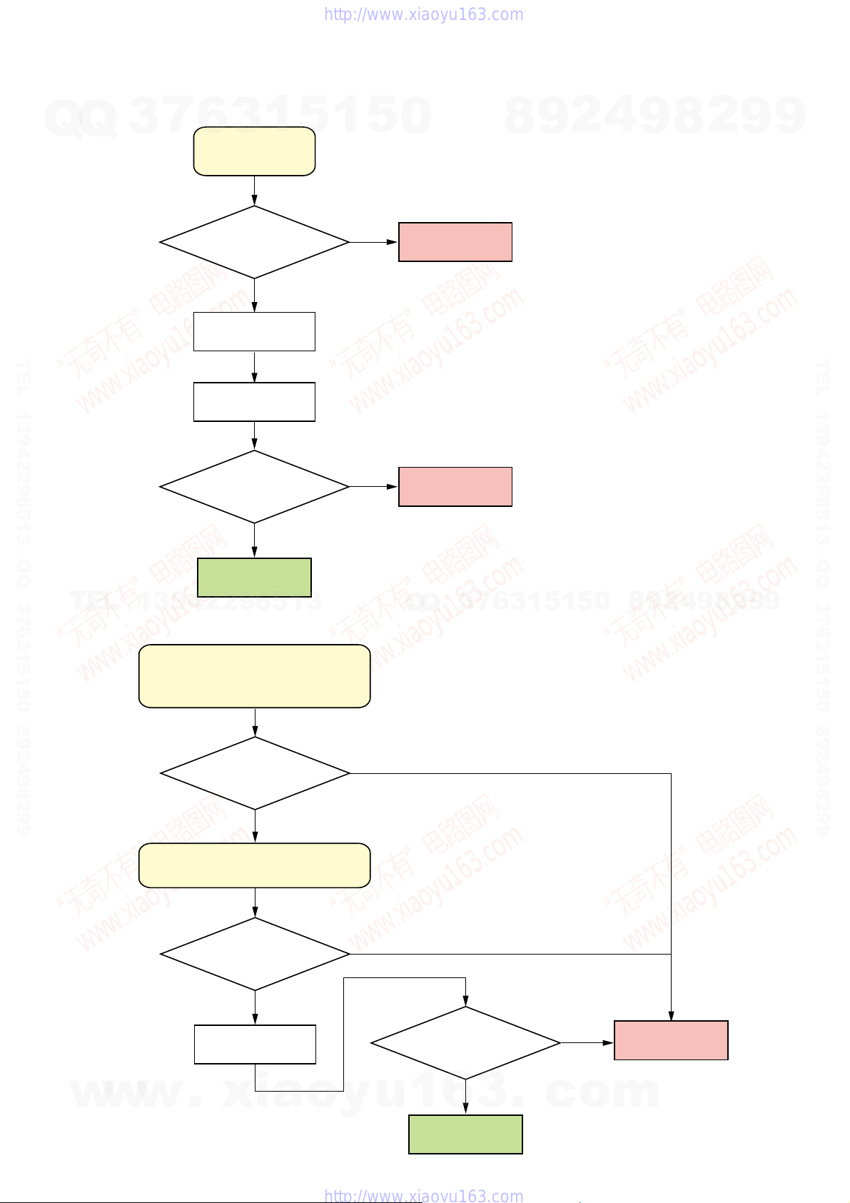
4-4. Display [E02] on FLD
7
Q
3
6
3
E02
1
5
1
5
0
Note: When E02 is displayed, the user data has
already broken due to system DATA Error.
8
9
2
4
9
8
2
9
9
Is the HDD free from
abnormal noises?
YES
Factory check
TEL 13942296513 QQ 376315150 892498299
Final check
Has the Final check ended
with success?
YES
END
TEL
13942296513
4-5. When playing a VIDEO, MP3, or JPG, the contents freeze
NO
Note: Performing “Final Check” will not erase the HDD data.
NO
Replace the HDD
Replace the HDD
7
3
Q
Q
Refer to “Note”.
*
Refer to “Note”.
*
1
3
6
5
1
5
0
8
9
2
4
9
8
2
9
TEL 13942296513 QQ 376315150 892498299
9
w
w
When playing a VIDEO, MP3, or JPG,
the contents freeze.
(Any error is not displayed on the FLD.)
Is the HDD free from
abnormal noises?
YES
Display the ATA/ATAPI history by using
“HDD Access Flow” on page 6-10.
Does the history show
no errors?
YES
Final check
Note: Performing “Final Check”
w
.
xia
will not erase the HDD data.
o
y
NO
NO
Has the Final check ended
with success?
u
1
6
END
YES
3
.
c
NO
o
Replace the HDD
Refer to “Note”.
*
m
— 9 —
4-6. Factory Check
1. Pull out and then reconnect the AC cable.
Q
Q
2. Press “ESC” key followed by “P.RUN” key to start Formatting.
3. When “B COMPLETE” appears, the Factory Check is complete.
4. Press “Power” button. The unit starts normally.
When “Factory Check” has finished completely without error, reset “Recording Error History” and “ATA/ATAPI History Error” with the
Clear key.
3
7
6
3
1
5
1
5
0
8
9
2
4
9
8
2
9
9
Recording Error History Display
07-03-19 12:36:06 ESFSYS INIT
07-03-19 12:36:06 HDD Zero MR
07-03-19 12:36:06 HDD Initialze
07-03-19 12:36:06 HDD Zero MR
07-03-19 12:27:27 Status NG
TEL 13942296513 QQ 376315150 892498299
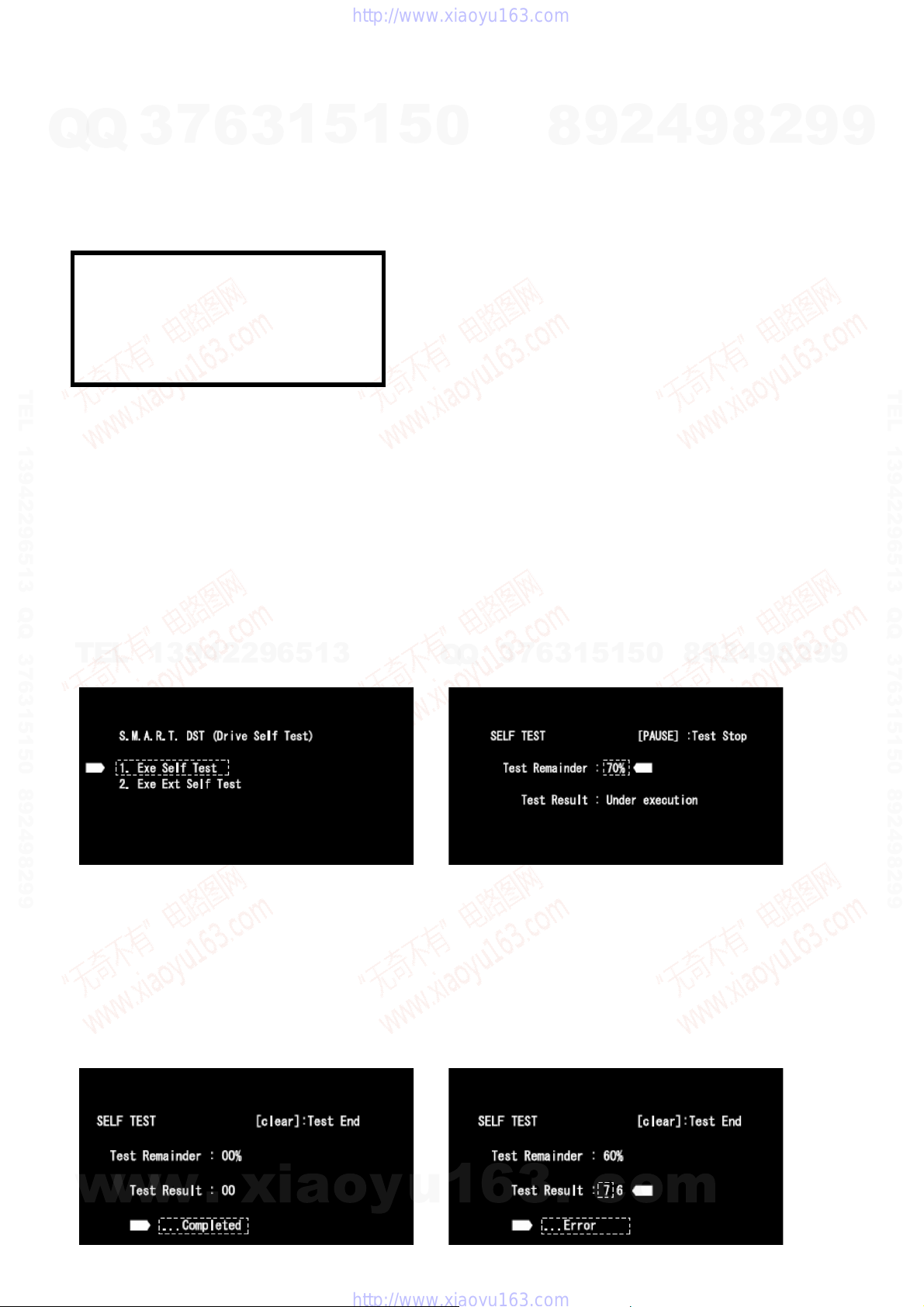
4-7. Final Check
4-7-1. SELF TEST (SMART TEST)
This is a simplified diagnosis for the HDD.
A serious failure in the HDD can be detected with this test.
Time required for testing: Approx. 60 sec.
How to start/terminate the diagnostic program
Use the remote control unit for servicing.
• How to start: Press “ESC”, “CX”, “0”, and “1” keys simultaneously.
• How to terminate: Press “ESC” key.
Execute Self-Test.
• Press “3” key on the remote control unit for servicing while the menu screen is displayed.
TEL
• When the following screen is displayed, press “1” key to start the Self-Test.
13942296513
Note: Write down the HDD information on the HDD return sheet before
replacing the HDD.
Note the information on pages 6-6, 6-7, 6-9, and 6-10 of Chapter 6,
“SERVICE MODE”.
When performing “Factory Check”, the data saved to the HDD by the
customer is erased.
Obtain customer consent before performing “Factory Check”.
“Recording Error History” and “AT A/A TAPI History Error”, see pages
6-9, 6-10 of Chapter 6, “SERVICE MODE”.
7
3
Q
Q
6
3
1
5
1
5
0
8
9
2
4
9
8
2
9
TEL 13942296513 QQ 376315150 892498299
9
Diagnosis results
• Without an error: “. . . Completed” is displayed.
Then, proceed to the Extended Self-Test.
• With an error: “. . . Error” is displayed. Look at the number in Test Result.
If the place value for tens is 1 or 2, execute the Self-Test again.
If it is from 3 to 7, the HDD must be replaced.
Note: If the result of the second test is the same, replacement of the HDD is required.
Example: No error Example: With an error
w
w
w
.
xia
o
y
u
— 10 —
Note: Performing “Self Test” will not erase the HDD data.Note: “2. Exe Ext Self Test” is not used.
1
6
3
.
c
o
m
Q
4-7-2. Performance Check
7
Q
3
Press “ESC” key, then “A.MON” key.
This is a reading test across all sectors of the HDD.
Data recorded on the HDD will not be erased, because no writing operation is performed.
Time required for testing: Approx. 45 min/160 G
When “Performance Check” finishes completely without error, reset “ATA/ATAPI History Error” with the Clear key.
FL display specification
HDD factory Check HDD performance Check
6
3
1
5
1
5
75 min/250 G
130 to 150 min/500 G
aNormal display aError display
0
8
9
2
4
9
aNormal display
8
2
9
aError display
9
TEL 13942296513 QQ 376315150 892498299
TEL
0:Factory Check start 0 0 000000
Power On
1:Power ON Test
2:
Random Write/Read/Compare Test
3:ID Sequential Read Verify Test
4:
OD Sequential Read Verify Test
5:Format
6:Power OFF Test
Power off
Power On15s
20s
Power off
13942296513
Power On
15s
20s
Power off
15s
* The logo for “Factory Check” and “Performance Check” is recorded in “ATA/ATAPI History Error”.
1 0 000000 81 0 00000
2 0 000000
3 **
*****
H M S
4 **
*****
H M S
5 FM
*****
H M S
6 0 000000
7 0 000000
8 0 000000
9 0 000000
A 0 000000
B COMPLETE
HDD ERR 01
HDD ERR 02
HDD ERR 03
HDD ERR 04
HDD ERR 05
HDD ERR 07
HDD ERR 09
Q
Q
Fig 1. FL Display Flow
80:Performance Check start
81:Power ON Test
82:
83:Power OFF Test
15s
84:Complete
7:Power ON Test
8:Power OFF Test
7
3
9:Power ON Test
a:Power OFF Test
b:Complete
Power On
all Sequential Read Verify Test
Power off
0
5
1
5
1
3
6
80 0 00000
82**
*****
H M S
83 0 00000
H M S
8 4 COMPLETE
4
2
9
8
HDD ERR 81
HDD ERR 82
8
9
2
9
TEL 13942296513 QQ 376315150 892498299
9
w
w
w
.
xia
o
y
u
1
6
3
— 11 —
.
c
o
m
5. CHANGED POINTS OF SERVICE MANUAL Revised-2
• When repairing or replacing parts, check for the correct combinations by referring to the table shown below.
Q
Q
1) Check for the correct combination in accordance with the MAIN IC (IC1001) mounted on the RD-065 board.
3
7
6
3
1
5
1
5
0
8
9
2
4
9
8
2
9
9
Type
AS
BS
CS
TEL 13942296513 QQ 376315150 892498299
DS
Check of Destination
Model
RDR-GX350
RDR-HX650
RDR-HX750
TEL
RDR-HX950
MAIN IC (IC1001)
RD-065 (AS) Board
IC1001: MC10050F1-105-LU1-A
(not supplied)
RD-065 (BS) Board
IC1001: MC10050F1-105-LU1-A
(not supplied)
RD-065 (CS) EM Board
IC1001: MC10050F1-505-LU1-A
(not supplied)
RD-065 (DS) EM Board
IC1001: MC10050F1-505-LU1-A
(not supplied)
Destination
AEP1, AEP2, UK, Russian
AEP1, AEP2, AEP3
AEP1, UK, Russian
AEP2
13942296513
AEP1
AEP2
RD-065 (AS)
RD-065 (CS)
RD-065 (BS)
RD-065 (DS)
RD-065 (BS)
RD-065 (DS)
RD-065 (BS)
RD-065 (DS)
RD-065 (BS)
RD-065 (DS)
RD-065 (BS)
RD-065 (DS)
AV Board
AV-114 (AG) Board
AV-114 (BG) Board
AV-118 (AG) EM
Board
AV-118 (AG) EM
AV-118 (BG) EM
Board
AV-118 (AG) EM
Q
VDC Board
VDC-001 (AG)
Board
Board
AV-114 (AG)
AV-114 (AG)
AV-118 (AG)
AV-114 (BG)
AV-118 (BG)
AV-114 (AG)
AV-118 (AG)
AV-114 (BG)
AV-118 (BG)
AV-114 (AG)
AV-118 (AG)
Q
3
–
7
6
3
DTC-001
–
DTC-001
–
DTC-001
–
DTC-001
5
1
–
DTC-001
–
DTC-001
–
Flexible Flat Cable
FVR-001 FFC
FVA-002 FFC
PV-145 HARNESS
PAE-002 HARNESS
(not supplied)
0
5
1
8
9
2
4
9
8
2
9
TEL 13942296513 QQ 376315150 892498299
9
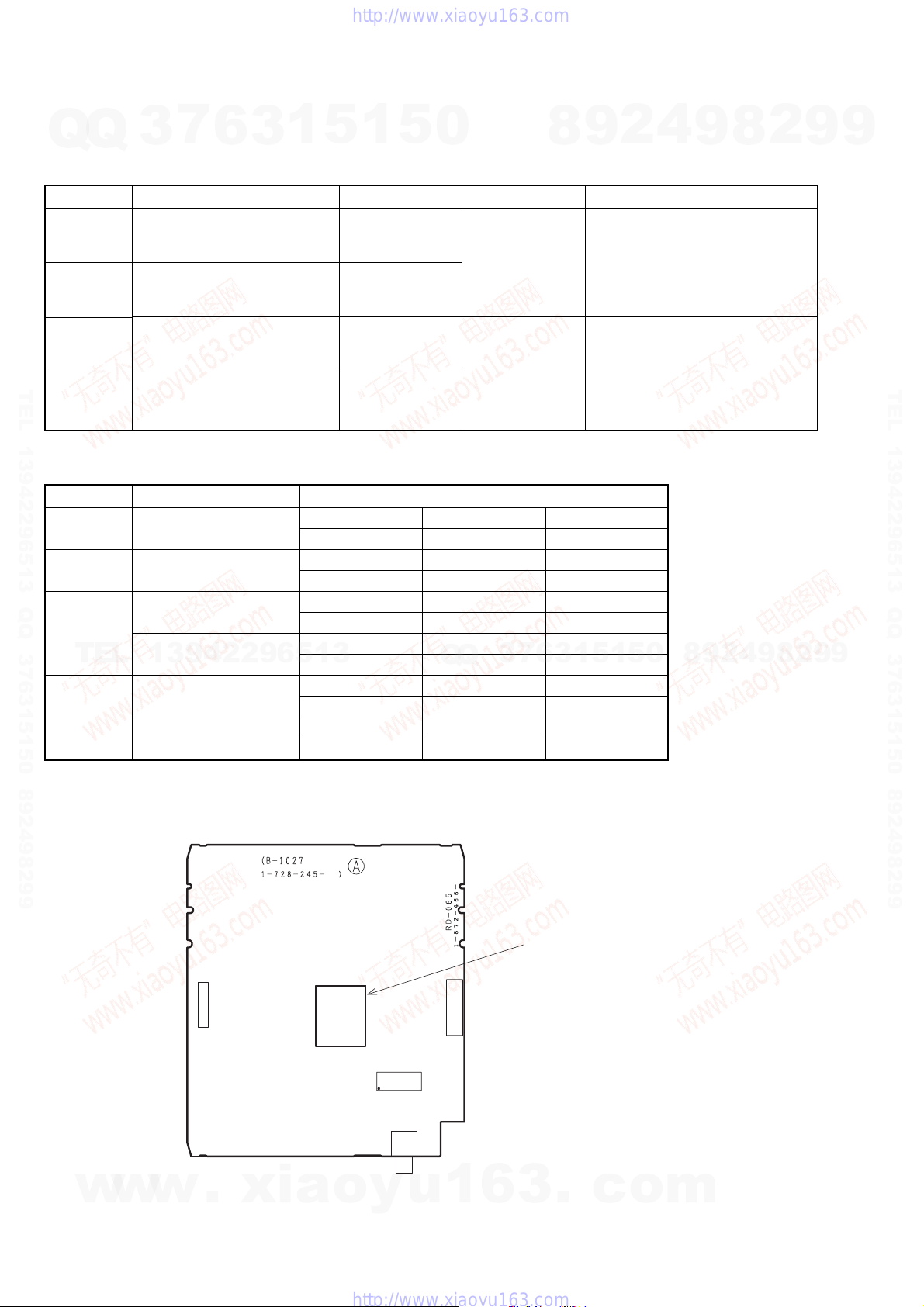
2) Location of MAIN IC (IC1001).
CN3802
w
w
w
.
xia
IC1001
o
IC1221
y
JA5701
u
CN4501
1
Check type name of IC1001
6
3
.
c
o
m
— 12 —
This section is extracted from instruction manual.
(RDR-HX750/HX950 : 2-899-893-E1 (1))
RDR-GX350/HX650/HX750/HX950
SECTION 1
GENERAL
7
Q
Q
TEL 13942296513 QQ 376315150 892498299
TEL
3
WARNING
To reduce the risk of fire or electric
shock, do not expose this apparatus
to rain or moisture.
To avoid electrical shock, do not
open the cabinet. Refer servicing to
qualified personnel only.
The mains lead must be changed
only at a qualified service shop.
Do not expose the battery to
excessive heat such as direct
sunlight, fire or the like.
This appliance is classified as a
CLASS 1 LASER product. The
CLASS 1 LASER PRODUCT
MARKING is located on the rear
of the unit.
CAUTION
The use of optical instruments with
this product will increase eye
hazard. As the laser beam used in
this DVD recorder is harmful to
eyes, do not attempt to disassemble
the cabinet.
Refer servicing to qualified
personnel only.
This label is located on the laser
protective housing inside the
enclosure.
2
13942296513
Precautions
6
3
• This unit operates on 220 –
240 V AC, 50/60 Hz. Check that
the unit’s operating voltage is
identical with your local power
supply.
• To prevent fire or shock hazard,
do not place objects filled with
liquids, such as vases, on the
apparatus.
• Install this system so that the
mains lead can be unplugged
from the wall socket
immediately in the event of
trouble.
GUIDE Plus+ and G-LINK are (1)
registered trademarks or
trademarks of, (2) manufactured
under license from and (3) subject
of various international patents and
patent applications owned by, or
licensed to, Gemstar-TV Guide
International, Inc. and/or its related
affiliates.
GEMSTAR-TV GUIDE
INTERNATIONAL, INC. AND/
OR ITS RELATED AFFILIATES
ARE NOT IN ANY WAY
LIABLE FOR THE ACCURACY
OF THE PROGRAM
SCHEDULE INFORMATION
PROVIDED BY THE GUIDE
PLUS+ SYSTEM. IN NO EVENT
SHALL GEMSTAR-TV GUIDE
INTERNATIONAL, INC. AND /
OR ITS RELATED AFFILIATES
BE LIABLE FOR ANY
AMOUNTS REPRESENTING
LOSS OF PROFITS, LOSS OF
BUSINESS, OR INDIRECT,
SPECIAL, OR
CONSEQUENTIAL DAMAGES
IN CONNECTION WITH THE
PROVISION OR USE OF ANY
INFORMATION, EQUIPMENT,
OR SERVICES RELATING TO
THE GUIDE PLUS+ SYSTEM.
1
5
1
Disposal of Old Electrical
& Electronic Equipment
(Applicable in the
European Union and
other European countries
with separate collection
systems)
This symbol on the product or on
its packaging indicates that this
product shall not be treated as
household waste. Instead it shall be
handed over to the applicable
collection point for the recycling of
electrical and electronic
equipment. By ensuring this
product is disposed of correctly,
you will help prevent potential
negative consequences for the
environment and human health,
which could otherwise be caused
by inappropriate waste handling of
this product. The recycling of
materials will help to conserve
natural resources. For more
detailed information about
recycling of this product, please
contact your local Civic Office,
your household waste disposal
service or the shop where you
purchased the product.
5
0
Q
Q
3
7
9
8
Precautions
This equipment has been tested
and found to comply with the
limits set out in the EMC
Directive using a connection
cable shorter than 3 metres.
On safety
Should any solid object or liquid
fall into the cabinet, unplug the
recorder and have it checked by
qualified personnel before
operating it any further.
About the hard disk dr ive
The hard disk has a high storage
density, which enables long
recording durations and quick
access to the written data.
However, it can easily be
damaged by shock, vibration or
dust, and should be kept away
from magnets. To avoid losing
important data, observe the
following precautions.
• Do not apply a strong shock to
the recorder.
• Do not place the recorder in a
location subject to mechanical
vibrations or in an unstable
location.
• Do not place the recorder on
top of a hot surface, such as a
VCR or amplifier (receiver).
• Do not use the recorder in a
place subject to extreme
changes in temperature
(temperature gradient less than
10 °C/hour).
• Do not move the recorder with
its mains lead connected.
• Do not disconnect the mains
lead while the power is on.
• When disconnecting the mains
lead, turn off the power and
make sure that the hard disk
drive is not operating (the
clock is displayed in the front
panel display for at least 30
seconds and all recording or
dubbing has stopped).
• Do not move the recorder for
one minute after you have
unplugged the mains lead.
1
5
1
3
6
• Do not attempt to replace or
4
2
upgrade the hard disk by
yourself, as this may result in
malfunction.
If the hard disk drive should
malfunction, you cannot recover
lost data. The hard disk drive is
only a temporary storage space.
About repairing the hard
disk drive
• The contents of the hard disk
drive may be checked in case
of repair or inspection during a
malfunction or modification.
However, the contents will not
be backed up or saved by
Sony.
• If the hard disk needs to be
formatted or replaced, it will
be done at the discretion of
Sony. All contents of the hard
disk drive will be erased,
including contents that violate
copyright laws.
On power sources
• The recorder is not
disconnected from the AC
power source (mains) as long
as it is connected to th e wall
outlet, even if the recorder
itself has been turned off.
• If you are not going to use the
recorder for a long time, be
sure to disconnect the recorder
from the wall outlet. To
disconnect the AC power cord
(mains lead), grasp the plug
itself; never pull the cord.
On placement
• Place the recorder in a location
with adequate ventilation to
prevent heat build-up in the
recorder.
• Do not place the recorder on a
soft surface such as a rug that
might block the ventilation
holes.
• Do not place the recorder in a
confined space such as a
bookshelf or similar unit.
• Do not place the recorder in a
location near heat sources, or
in a place subject to direct
sunlight, excessive dust, or
mechanical shock.
0
5
9
8
9
8
2
• Do not place the recorder in an
2
9
8
9
,continued
2
inclined position. It is
designed to be operated in a
horizontal position only.
• Keep the recorder and discs
away from equipment with
strong magnets, such as
microwave ovens, or large
loudspeakers.
• Do not place heavy objects on
the recorder.
On recording
Make trial recordings before
making the actual recording.
On compensation for lost
recordings
Sony is not liable and will not
compensate for any lost
recordings or relevant losses,
including when recordings are
not made due to reasons
including recorder failure, or
when the contents of a recording
are lost or damaged as a result of
recorder failure or repair
undertaken to the recorder. Sony
will not restore, recover, or
replicate the recorded contents
under any circumstances.
Copyrights
• Television programmes, films,
video tapes, discs, and other
materials may be copyrighted.
Unauthorized recording of
such material may be contrary
to the provisions of the
copyright laws. Also, use of
this recorder with cable
television transmission may
require authorization from the
cable television transmitter
and/or programme owner.
• This product incorporates
copyright protection
technology that is protected by
U.S. patents and other
intellectual property rights.
Use of this copyright
protection technology must be
authorized by Macrovision,
and is intended for home and
other limited viewing uses
only unless otherwise
authorized by Macrovision.
Reverse engineering or
disassembly is prohibited.
4
9
9
3
9
TEL 13942296513 QQ 376315150 892498299
w
w
• This Product include s
®
fonts licenced
FontAvenue
by NEC corporation.
FontAvenue is a registered
trademark of NEC
corporation.
Copy guard function
Since the recorder has a copy
guard function, programmes
received through an external
tuner (not supplied) may contain
copy protection signals (copy
guard function) and as such may
not be recorda bl e, de pe nd i ng o n
the type of signal.
IMPORTANT NOTICE
Caution: This recorder is
capable of holding a still
video image or on-screen
display image on your
television screen
indefinitely. If you leave the
still video image or onscreen display image
displayed on your TV for an
extended period of time you
risk permanent damage to
your television screen.
Plasma display panels and
projection televisions are
especially susceptible to this.
If you have any questions or
problems concerning your
recorder, please consult your
nearest Sony dealer.
w
4
About this manual
Check your model name
The instructions in this
manual are for 2 models:
RDR-HX750 and RDRHX950. Check your model
name by looking at the front
panel of the recorder.
• In this manual, the internal
• Icons, such as , listed
• Instructions in this m anual
• The on-screen display
• The explanations regarding
.
xia
hard disk drive is written as
“HDD,” and “disc” is used as a
general reference for the HDD,
DVDs, or CDs unless
otherwise specified by the text
or illustrations.
DVD
at the top of each explanation
indicate what kind of media
can be used with the function
being explained.
describe the controls on the
remote. You can also use the
controls on the recorder if they
have the same or similar
names as those on the remote.
illustrations used in this
manual may not match the
graphics displayed on your TV
screen.
DVDs in this manual refer to
DVDs created on this recorder.
The explanations do not apply
to DVDs that are created on
other recorders and played
back on this recorder.
o
y
u
1
6
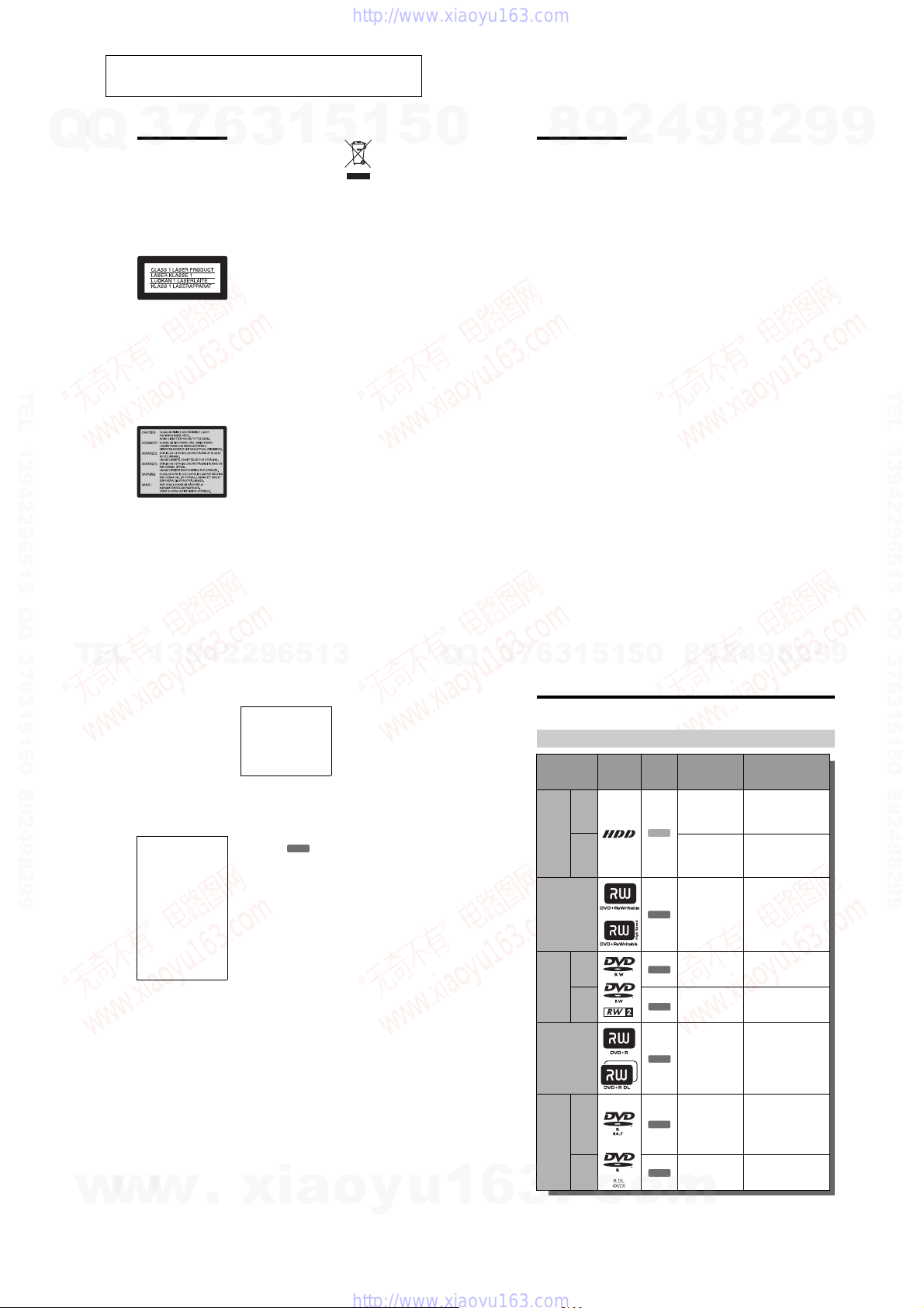
Quick Guide to Disc Types
Recordable and playable discs
Type Disc Logo
VR
mode
Hard disk
drive
(internal)
Video
mode
DVD+RW
VR
mode
DVD-RW
Video
mode
DVD+R
DVD+R DL
VR
DVD-R
mode
DVD-R DLVideo
mode
3
.
c
o
Icon used
in this
manual
HDD
+
RW
-
RWVR
-
RWVideo
+
R
-
RVR
-
RVideo
Formatting
(new discs)
Select “Video Mode
Off” in “HDD
Recording Format”
(page 122)
Select “Video Mode
On” (default) in
“HDD Recording
Format” (page 122)
Automatically
formatted in +VR
mode (DVD+RW
VIDEO)
Format in VR mode
(page 31)
Format in Video
mode (page 31)
Automatically
formatted in +VR
mode (DVD+R
VIDEO)
Format in VR mode
(page 31)
Formatting is
performed in the
“Format” setup
(page 42).
Automatically
formatted in Video
mode
m
*1
Compatibility with other
DVD players (finalising)
Dub HDD contents to a
DVD (VR mode) to play
on other DVD players
Dub HDD contents to a
DVD (Video mode) to play
on other DVD players
Playable on DVD+RW
compatible players
(automatically finalised)
Playable only on VR mode
compatible players
(finalisation unnecessary)
Playable on most DVD
players (finalisation
necessary) (page 40)
Playable on most DVD
players (finalisation
necessary) (page 40)
Playable only on DVD-R
in VR mode compatible
players (finalisation
necessary) (page 40)
Playable on most DVD
players (finalisation
necessary) (page 40)
,continued
9
1-1
Usable disc versions (as of April 2007)
Q
Q
• 8x-speed or slower DV D+RWs
• 6x-speed or slower DV D-RWs (Ver.1.1,
Ver.1.2 with CPRM
• 16x-speed or slower DVD+Rs
• 16x-speed or slower DVD-Rs (Ver.2.0,
Ver.2.1 with CPRM
• 8x-speed or slower D V D+R DL (Double
Layer) discs
• 8x-speed or slower DV D-R DL (Dual
Layer) discs (Ver.3.0 with CPRM
“DVD+RW,” “DVD-RW,” “DVD+R,” “DVD+R
DL,” “DVD-R,” and “DVD-R DL” are trademarks.
*1
When an unformatted DVD-R is inserted into
this recorder, it is automatically formatted in
Video mode. To format a new DVD-R in VR
mode, format in the “Format” setup (page 42).
*2
CPRM (Content Protection for Recordable
Media) is a coding technology that protects
copyrights for images.
Discs that cannot be recorded on
• DVD-RAMs
TEL 13942296513 QQ 376315150 892498299
10
TEL
3
*2
)
*2
)
7
*2
)
6
3
1
13942296513
5
1
5
0
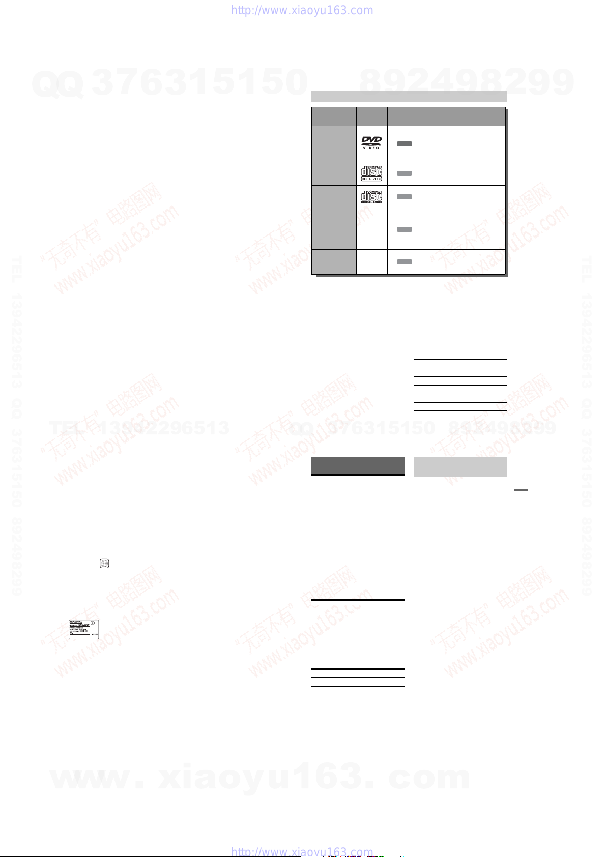
Playable discs
Type Disc Logo
DVD VIDEO
VIDEO CD
CD
DATA DVD —
DATA CD —
“DVD VIDEO” and “CD” are trademarks.
DivX, DivX Certified, and associated logos are
trademarks of DivX, Inc. and are used under
license.
®
is a video file compression technology,
DivX
developed by DivX, Inc.
* If the DVD-RAM has a removable cartridge,
remove the cartridge before playback.
Discs that cannot be played
• PHOTO CDs
• CD-ROMs/CD-Rs/CD-RWs that are
recorded in a format different from the
formats mentioned in the table above.
• Data part of CD-Extras
• BDs
• HD DVDs
• Discs recorded with an AVCHD-
compatible DVD video camera
3
Q
Q
7
8
6
3
9
1
4
2
Icon used in
this manual
5
Characteristics
Discs such as movies that can be
purchased or rented
This recorder also recognises DVD-
DVD
RAMs* as DVD Video compatible
discs.
VIDEO CDs or CD-Rs/CD-RWs in
VCD
VIDEO CD/Super VIDEO CD format
Music CDs or CD-Rs/CD-RWs in
CD
music CD format
DVD+RWs/DVD+Rs containing MP3
audio tracks or DivX video files
DVD-RWs/DVD-Rs/DVD-RAMs*/
DATA DVD
DVD-ROMs containing MP3 audio
tracks, JPEG image files or DivX video
files
CD-ROMs/CD-Rs/CD-RWs
containing either MP3 audio tracks,
DATA CD
JPEG image files or D ivX video files
• DVD-ROMs/DVD+RWs/DVD-RWs/
DVD+Rs/DVD-Rs that do not contain
DVD Video, DivX video, JPEG image
files, or MP3 audio tracks.
• DVD Audio discs
• Cartridge-only type DVD-RAMs.
• HD layer on Super Audio CDs
• DVD VIDEOs with a different region code
(page 12).
• DVDs that were recorded on a different
recorder and not correctly finalised.
Maximum recordable number of titles
Disc Number of titles
HDD* 999
DVD-RW/DVD-R 99
DVD+RW/DVD+R 49
DVD+R DL 49
DVD-R DL 99
* The maximum length for one title is 12 hours.
0
5
1
9
8
9
8
2
,continued
9
4
2
11
8
9
2
9
9
TEL 13942296513 QQ 376315150 892498299
9
Note on playback operations of DVD
VIDEOs/VIDEO CDs
Some playback operations of DVD VIDEOs/
VIDEO CDs may be intentionally set by
software producers. Since this recorder plays
DVD VIDEOs/VIDEO CDs according to the
disc contents the software producers
designed, some playback features may not be
available. See the instructions supplied with
the DVD VIDEOs/VIDEO CDs.
Region code (DVD VIDEO only)
Your recorder has a region code printed on
the rear of the unit and will only play DVD
VIDEOs (playback only) labelled with
identical region codes. This sy stem is u sed to
protect copyrights.
DVD VIDEOs labelled will also play
on this recorder.
If you try to play any other DVD VIDEO, the
message “Playback proh ib ited by region
code.” will appear on the TV screen.
Depending on the DVD VIDEO, no region
code indication may be labelled even t hough
playing the DVD VIDEO is prohibited by
area restrictions.
Music discs encoded with copyright
protection technologi es
This product is designed to play back discs
that conform to the Compact Disc (CD)
standard.
Recently, various music discs encoded with
copyright protecti on technologies are being
marketed by some record companies. Please
be aware that among those discs, there are
some that do not conform to the CD standard
and may not be playable by this product.
Note on DualDiscs
A DualDisc is a two sided disc product which
mates DVD recorded material on one side
with digital audio material on the other side.
However, since the audio m at erial side does
not conform to the Compact Disc (CD)
standard, playback on this produ ct is not
guaranteed.
w
12
w
w
ALL
Region code
b Notes
• Some DVD+RWs/DVD+Rs, DVD-RWs/DVDRs, DVD-RAMs, or CD-RWs/CD-Rs cannot be
played on this recorder due to the recording
quality or physical condition of the disc, or the
characteristics of the recording device and
authoring software. The disc will not play if it has
not been correctly finalised. For more
information, see the operating ins tructions for t he
recording device.
• You cannot mix VR mode and Video mode on the
same DVD-RW. To change the disc’s format,
reformat the disc (page 42). Note that the disc’s
contents will be erased after reformatting.
• You cannot shorten the time required for
recording even with high-speed discs.
• It is recommended that you use discs with “For
Video” printed on their packaging.
• You cannot add new recordings to DVD+Rs,
DVD-Rs, or DVD-RWs (Video mode) that
contain recordings made on other DVD
equipment.
• In some cases, you may not be able to add new
recordings to DVD+RWs that contain recordings
made on other DVD equipment. If you do add a
new recording, note that this recorder will re write
the DVD menu.
• You cannot edit recordings on DVD+RWs,
DVD-RWs (Video mode), DVD+Rs, or DVD-Rs
that are made on other DVD equipment.
• If the disc contains PC data unrecognizable by
this recorder, the data may be erased.
• You may not be able to record, edit, or dub on
some recordable discs, depending on the disc.
• Do not insert any discs that cannot be recorded or
played on this recorder. This may cause the
recorder to malfunctio n.
.
xia
o
y
u
Hookups and Settings
Hooking Up the Recorder
Follow steps 1 through 6 to hook up and
adjust the settings of the recorder. Do not
connect the mains lead until you reach
“Step 4: Connecting the Mains Lead” on
page 20.
b Notes
• See “Specifications” (page 138) for a list of
supplied accessories.
• Plug in cords securely to prevent unwanted noise.
• Refer to the instruc tions supplied with the
components to be connected.
• You cannot connect this recorder to a TV that
does not have a SCART or video input jack.
• Be sure to disconnect the mains lead of each
component before connecting.
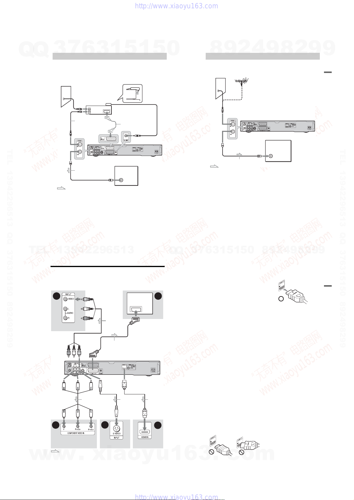
Step 1: Connecting the
Aerial Cable and Set Top
Box Controller
Select one of the following aeri al hookups.
Do NOT set “LINE 1 In” to “Decoder” in the
“Video In/Out” setup (page 115) w hen
making connection A.
If you have Hookup
Set top box receiver A (page 14)
No set top box receiver B (page 15)
If the set top box receiver can output RGB
signals
This recorder accepts RGB signals. If the set
top box receiver can output RGB signals,
connect the TV SCART connector on the set
top box receiver to the LINE 1/DECODER
jack, and set “LINE 1 In” to “RGB” in the
“Video In/Out” setup (page 115). See the
instructions supplied with the set top box
receiver.
1
6
3
.
Using the set top box receiver
control function
The set top box receiver control function can
be used with hookup A. It allows the recorder
to control a set top box receiv er v i a th e
supplied set top box controlle r. The recorder
controls programme positions on the set top
box receiver for timer r ecording. You can
also use the recorder’s remote control to
change programme positions on the set top
box receiver whenever the set top box
receiver and recorder are tur ned on.
To use the set top box receiver control
function, you need to connect the set top box
controller (page 14). After setting up the set
top box receiver control, check that the
recorder can correctly control the set top box
receiver (page 24).
b Notes
• If your aerial is a flat cable (300-ohm twin lead
cable), use an external aerial connector (not
supplied) to connect the aerial to the recorder.
• If you have separate cables for AERIAL
antennas, use an AERIAL UHF/VHF band mixer
(not supplied) to connect the aerial to the
recorder.
• If you disconnect the recorder’s mains lead, you
will not be able to view the signals fro m th e
connected set top box receiver.
c
o
m
,continued
Hookups and Settings
13
1-2
Q
Q
7
3
A: Connecting a set top box receiver
With this hookup, you can recor d any programme position on the set top box receiver.
To watch cable programmes, you need to matc h the p rogr amme posit ion o n the re cord er to the
aerial output programme position on the set top box receiver.
Wall
6
Aerial cable*
(not supplied)
to AERIAL IN
Set top box
receiver
ANT IN
TO TV
1
3
Set top box
controller
(page 13)
1
5
Place the set top box controller
near the remote sensor on the
set top box receiver.
SCART cord*
(not supplied)
1
2
to G-LINK
5
0
TEL 13942296513 QQ 376315150 892498299
to AERIAL OUT
Aerial cable
(supplied)
: Signal flow
*1
If your set top box receiver does not have an aerial output jack, connect t he aerial cable to the recorder’s
AERIAL IN jack.
*2
Connect only if your set top box receiver has a SCART connector.
to aerial input
DVD recorder
TV
4
2
9
8
B: Connecting the aerial cable only (no set top box receiver)
Use this hookup if you watch cabl e pr ogramme position without a set top box receiver. Also
use this hookup if you are connecting only an aerial antenna.
With this hookup, you can record any programme position by selecting the programme position
on the recorder.
Wall
to AERIAL IN
to AERIAL OUT
to aerial input
Aerial cable (supplied)
: Signal flow
9
TV
8
2
DVD recorder
9
9
Hookups and Settings
TEL 13942296513 QQ 376315150 892498299
TEL
w
w
14
13942296513
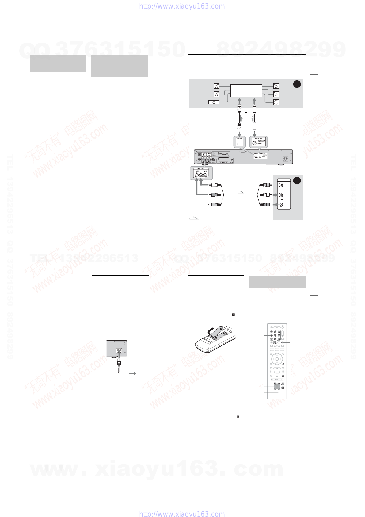
Step 2: Connecting the Video Cords/HDMI Cord
Select one of the following patterns, A through E, according to the input jack on your TV
monitor, projector, or audio component such as an AV amplifier (re ceiver). This will enable
you to view pictures.
B
TV
DVD recorder
HDMI cord
(not supplied)
TV, projector, or audio
component
y
TV, projector, or audio
component
(green)
to COMPONENT
VIDEO OUT
(green)
D
w
16
to LINE 2 OUT
(VIDEO)
TV, projector, or audio
component
: Signal flow
.
SCART cord (not supplied)
(yellow)
to T LINE 3 – TV
(red)(blue)
Component video
cord (not supplied)
(red)(blue)
xia
Audio/video
cord (not
supplied)
to LINE 2 OUT
(S VIDEO)
S-video cord
(not supplied)
C
TV, projector, or audio
component
to HDMI OUT
o
A
E
u
Q
Q
1
3
6
5
1
5
1
3
6
7
A SCART input jack
When setting “LINE 3 Out” to “S-Video” or
“RGB” in the “Video In/Out” setup
(page 115), use a SCART cord that conforms
to the selected signal.
B Video input jack
You will enjoy standard quality images.
C S VIDEO input jack
You will enjoy high quality image s.
D Component video input jacks ( Y, PB/CB,
R/CR)
P
You will enjoy accurate colour repr oduction
and high quality images.
If your TV accepts progressive 525p/625p
format signals, use this connection and set
“Progressive” to “Compatible” in the “Easy
Setup” setup (page 23). Then set
“Component Video Out” to “Progressive” in
the “Video In/Out” setup to send progressive
video signals. For details, see “Component
Video Out” on page 115.
E HDMI input jack
Use a certified HDMI cord (not supplied) to
enjoy high quality digital picture and sound
through the HDMI OUT jack.
When connecting a Sony TV that is
compatible with the HDMI control function,
see page 18.
To see the signals from the connected set top
box receiver when the set top box receiver is
connected to the recorder us in g a SCART
cord only, turn the recorder on.
When connecting to the HDMI jack
Follow the steps below. Improper handling
may damage the HDMI jack and the
connector.
1 Carefully align the HDMI jack on the
rear of the recorder and the HDMI
connector by checking their shapes.
Make sure the connector is no t up s ide
down or tilted.
Connector is upside down Not straight
3
.
c
0
o
9
4
2
9
8
2 Insert the HDMI connector straight into
the HDMI jack.
Do not bend or apply pressure to the
HDMI connector.
b Notes
• Be sure to disconnect the HDMI cord when
moving the recorder.
• Do not apply too much pressur e to the cabine t
wall, if you place the recorder on the cabinet with
the HDMI cord connected. It may damage the
HDMI jack or the HDMI cord.
• Do not twist the HDMI connector while
connecting to or disconnecting from the HDMI
jack to avoid damaging the HDMI jack and
connector.
When playing “wide screen” images
Some recorded images may not fit your TV
screen. To change the picture si ze, see
page 122.
If you are connecting to a VCR
Connect your VCR to the LINE 1/
DECODER jack on the recorder (page 26).
b Notes
• Do not connect more than one type of video cord
between the recorder and your TV at the same
time.
• Do not make connections A and E at the same
time.
• When you connect the recorder to your TV via the
SCART jacks, the TV’s input source is set to the
recorder automatically when you start playback.
If necessary, press the TV t button on the
remote to return the input to the TV.
• If you connect the recorder to a TV with
SMARTLINK, set “LINE 3 Out” to “Video” in
the “Video In/Out” setup.
• You cannot connect the HDMI OUT jack
(connection E) to DVI jacks that are not HD CP
compliant (e.g., DVI jacks on PC displays).
• Component video and RGB signals are not output
when using the HDMI connection.
* This DVD recorder incorporates High-Definition
Multimedia Interface (HDMI™) technology.
HDMI, the HDMI logo and High-Definition
Multimedia Interface are trademarks or registered
trademarks of HDMI Licensing LLC.
m
8
9
2
,continued
9
15
Hookups and Settings
17
1-3
7
Q
Q
About the SMARTLINK
features (for SCART
connections only)
If the connected TV (or other connected
equipment such as a set top box) complies
with SMARTLINK, NexTView Link
MEGALOGIC
CINEMALINK
LINK
following SMARTLINK features.
• TV Direct Rec. (page 32)
• One-Touch Play (page 61)
• Preset Download
You can download the tuner pr es et data
from your TV to this recorder, and tune the
recorder according to that data in “Easy
Setup.”
• NexTView Download
You can easily set the timer by us ing the
NexTView Download function on your TV.
To prepare for the SMART LINK features
Set “LINE 3 Out” to “Video” in the “Video
In/Out” setup (page 115) and
TEL 13942296513 QQ 376315150 892498299
“SMARTLINK” to “This Recorder Only” in
the “Options” setup (page 128).
b Notes
• For correct SMARTLINK connection, you will
need a SCART cord that has the full 21 pins.
Refer to your TV’s instruction manual as well for
this connection.
• Not all TVs respond to the functions above.
*1
“MEGALOGIC” is a registered trademark of
Grundig Corporation.
*2
“EASYLINK” and “CINEMALINK” are
trademarks of Philips Corporation.
*3
“Q-Link” and “NexTView Link” are trademarks
of Panasonic Corporation.
*4
“EURO VIEW LINK” is a trademark of Toshiba
Corporation.
*5
“T-V LINK” is a trademark of JVC Corporation.
18
TEL
3
*1
, EASYLINK*2,
*2
, Q-Link*3, EURO VIEW
*4
, or T-V LINK*5, you can enjoy the
13942296513
6
About the HDMI Control
functions for ‘BRAVIA’ Theatre
Sync (for HDMI connections
only)
By connecting Sony components that are
*3
,
compatible with the HDMI Control function
with an HDMI cord (not supplied), operation
is simplified as below:
• One-Touch Play (page61)
• System Power-Off
When you turn the TV off by using the
power button on the TV’s remote, the
components compatible with the HDMI
Control function turn off automatically.
To prepare for the ‘BRAVIA’ Theatre Sync
features
Set “HDMI Control” to “On” in the “HDMI
Output” setup (page 126). For details on TV
settings, refer to the operating instructions
supplied with the TV.
b Notes
• Depending on the connected component, the
HDMI Control function may not work. Refer to
the operating instructions supplied with the
component.
• The recorder supports only the playback option of
HDMI Control. “Player” appears on the TV
screen when using the HDMI Control functions.
3
1
5
1
5
0
Step 3: Connecting the Audio Cords/HDMI Cord
Select one of the following patterns, A or B, according to the input jack on your TV monitor,
projector, or audio component such as an AV a mplifier (r eceiver). This will enable you to listen
to sound.
* The yellow plug is used for video signals (page 16).
A Digital audio input jack
If your audio component has a Do lb y
Digital, DTS*2, or MPEG audio decoder and
a digital input jack, use this connection. You
can enjoy Dolby Digital (5.1ch), DTS
(5.1ch), and MPEG audio (5.1ch) surround
effects.
Q
Q
Rear (L)
Front (L)
Centre
: Signal flow
3
[Speakers]
7
9
8
Audio component with
a decoder
HDMI cord
(not supplied)
to HDMI OUT
to LINE 2 OUT (R-AUDIO-L)
(white)
(red)
(yellow)*
6
3
Audio/video cord
(not supplied)
*1
5
1
4
2
or
If you connect a Sony audio comp onent that
is compatible with the HDMI control
function, refer to the operating instructions
supplied with the audio component.
0
5
1
9
[Speakers]
Rear (R)
Front (R)
Subwoofer
to coaxial/HDMI digital input
Coaxial digital cord
(not supplied)
to DIGITAL OUT (COAXIAL)
DVD recorder
INPUT
TV, projector, or
audio component
9
8
VIDEO
L
AUDIO
R
(yellow)
(white)
(red)
8
2
A
B
,continued
9
4
2
Hookups and Settings
19
8
9
2
9
9
TEL 13942296513 QQ 376315150 892498299
9
B Audio L/R (left/right) input jacks
This connection will use your TV’s or audio
component’s two speake rs for sound.
z Hint
For correct speaker location, see the operating
instructions supplied with the connected
components.
b Notes
• Do not connect your TV’s audio out put ja c ks to
the LINE IN (R-AUDIO-L) jacks at the same
time. This will cause unwanted noise to come
from your TV’s speakers.
• With connection B, do not connect the LINE IN
(R-AUDIO-L) and LINE 2 OUT (R-AUDIO-L)
jacks to your TV’s audio output jacks at the same
time. This will cause unwanted noise to come
from your TV’s speakers.
• With connection A, after you have completed the
connection, make the appropriate settings in the
“Audio Out” setup (page 117). Otherwise, no
sound or a loud noise will come from your
speakers.
• When you connect the recorder to an audio
component using an HDMI cord, you will need to
do one of the following:
– Connect the audi o component to the TV with
the HDMI cord, or
– Connect the recorder to the TV with a video
cord other than HDMI cord (component video
cord, S-video cord, or audio/video cord).
*1
Manufactured under license from Dolby
Laboratories.
“Dolby” and the double-D symbol are
trademarks of Dolby Laboratories.
*2
“DTS” and “DTS Digital Out” are registered
trademarks of DTS, Inc.
Step 4: Connecting the
Mains Lead
Connect the supplied mains lead to the AC IN
terminal of the recorder. Th en plug the
recorder and TV mains leads (AC power
cords) into the mains. After you connect the
mains lead, you must wait for a short
while before operating the recorder.
You can operate the recorder on ce t h e front
panel display lights up and the r ecorder enters
standby mode.
If you connect additional equipm ent to this
recorder (page 26), be sure to conne ct th e
mains lead after all connections are complete.
1
to AC IN
2
to mains
Step 5: Preparing the
Remote
You can control the recorder us i ng t h e
supplied remote. Insert two R6 (size AA)
batteries by matching the 3 and # e nds on
the batteries to the markings inside the
battery compartment. When using the
remote, point it at the remote sensor on the
recorder.
b Notes
• If the supplied remote inter f ere s with your other
Sony DVD recorder or player, change the
command mode number for this recorder
(page 22).
• Use the batteries correctly to avoid possible
leakage and corrosion. Should leakage occur, do
not touch the liquid with bare hands. Observe the
following:
– Do not use a new battery with an old battery, or
batteries of different manufacturers.
– Do not attem p t to r ech a r ge the b at te ri e s.
– If you do not intend to use th e re mote for an
extended period of time, remo ve the batteries.
– If battery leakag e occ u rs, wipe out any liqui d
inside the battery compartment, and insert new
batteries.
• Do not expose the remote sensor (marked on
the front panel) to strong light, such as direct
sunlight or a lighting apparatus. The recorder may
not respond to the remote.
• When you replace the batteries of the remote, the
code number and Command Mode may be reset
to the default setting. Set the appropriate code
number and Command Mode again.
Controlling TVs with the
remote
You can adjust the remote’s signal to control
your TV.
b Notes
• Depending on the connected unit, you may not be
able to control your TV with some or all of the
buttons below.
• If you enter a new code number, the code number
previously entered will be erased.
Number
buttons
TV 2 +/–
TV PROG
+/–
1 Hold down TV [/1 located at the
bottom of the remote.
Do not press the [/1 button at the top of
the remote.
2 With TV [/1 pressed down, enter the
TV’s manufacturer code using the
number buttons.
For instance, to enter “09,” press “0” then
“9.” After you enter the last number,
release the TV [/1 button.
TV/DVD
DISPLAY
x
TV [/1
TV t
Hookups and Settings
w
20
w
w
.
xia
o
y
u
1
6
3
1-4
.
c
o
m
,continued
21
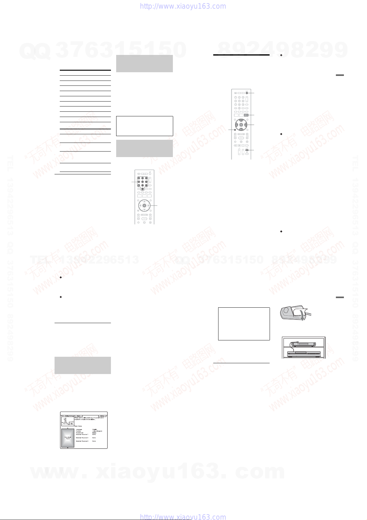
Code numbers of controllable TV s
7
Q
Q
TEL 13942296513 QQ 376315150 892498299
TEL
3
If more than one code number is listed,
try entering them one at a time until yo u
find the one that works with your TV.
Manufacturer Code number
Sony 01 (d efa ul t)
Hitachi 24
JVC 33
Panasonic 17, 49
Philips 06, 08
Samsung 71
Sanyo 25
Thomson 43
Toshiba 38
The remote performs the following:
Buttons Operations
TV [/1 Turns your TV on or
TV 2 (volum e)
+/–
TV PROG +/– Selects the
TV t (input
select)
To operate the TV/DVD bu tton
(for SCART connections only )
The TV/DVD button switches be tween TV
mode and DVD mode. Press the TV/DVD
button when in stop mode or no menu appears
on the TV screen. Point your remote at the
recorder when using this button.
TV mode: switch to this when you use the
TV’s tuner mainly. When you start play back,
the input source for the TV is set to the
recorder automatically. When you press the
x (stop) button during playback, the
programme tuned by the TV or external
equipment appears.
DVD mode: switch to this when y ou use the
recorder’s tuner mainly. When you press the
x (stop) button during playback, the
programme tuned by the recorder appears.
To check the current mode, pr ess DISPLAY
(page 35).
22
13942296513
6
off.
Adjusts the volume
of your TV.
programme position
on your TV.
Switches your TV’s
input source.
1
3
5
If you have a Sony DVD player
or more than one Sony DVD
recorder
If the supplied remote interferes with your
other Sony DVD recorder or player, set the
command mode number for this recorder and
the supplied remote to one that differs from
the other Sony DVD recorder or player after
you have completed “Step 6: Easy Setup.”
The default command mode setting for this
recorder and the supplied remote is DVD3.
You can check the current Co m m and Mode
in the front panel d i splay. For details , see
page 127.
The default command mode setting for this
recorder and the supplied remote is DVD3.
The remote does not function if different
command modes are set for the re corder and
remote. Set the same command mode.
Changing programme positions
of the recorder using the
remote
You can change programme p ositions of the
recorder using the number b ut to n s .
Number
buttons
Example: for channel 50
Press “5,” “0,” then press ENTER.
1
5
ENTER
0
Q
Q
3
7
4
2
9
8
Step 6: Easy Setup
Make the basic adjustments by f ollowing the
on-screen instructions in “Easy Setup.”
Be careful not to disconnect the cables or exit
the “Easy Setup” function during this
procedure.
[/1
GUIDE
</M/m/,,
1
5
ENTER
TV [/1
0
O
RETURN
1 Turn on the recorder and your TV.
Then switch the i nput selector on your
TV so that the signal from the recorder
appears on your TV screen.
The “Language” display appe ars.
• If the “Language” display does not
appear, select “Easy Setup” in the
“Basic” setup from “Initial Setup” in
the System Menu (page110).
2 Select a language for t he on-screen
displays using M/m, and press
ENTER.
The initial settings message appears.
3 Select “Start” using M/m, and press
ENTER.
Follow the on-screen instructions to
make the following settings.
5
1
3
6
Auto Channel Setting
9
If you connect a TV to this recorder not
using SMARTLINK, select “Auto
Scan.” Then select your coun t ry /r egion
using </,, and press ENTER. The
programme position order will be set
according to the country/regi on you
select.
If you connect a TV to this recorder with
SMARTLINK, select “Download from
TV.” Then select your country/region
using </,, and press ENTER. The
tuner preset data will be down lo aded
from your TV to this re corder. (For
details, refer to the operating instruction s
supplied with your TV.)
To skip this setting, select “Do not set.”
To set the programme positions
manually, see page 111.
Clock Setting
Select “Auto” when a programme
position in your local area broadcasts a
time signal. The “Auto Clock Setting”
display appears.
1 Select the programme position of the
station that carries a time signal
using </,.
2 Select “Start” using m, and press
ENTER.
If a clock signal cannot be found,
press O RETURN, and set the
clock manually.
Select “Manual” to set the clock
manually. The “Manual Clock Setting”
display appears.
1 Select the tim e zone for your area
using </,, and press m.
2 Select “On” if yo u ar e now on
summer time, and press ENTER.
3 Set the day, mont h, year, hour, and
minutes using </M/m/,, and
press ENTER to start the clock.
TV Screen Size (page 122)
If you have a wide-screen TV, selec t
“Wide (16:9).” If you have a standard
TV, select “Standard (4:3).” This will
determine how “wide-screen” images are
displayed on your TV.
2
9
8
8
4
2
9
8
9
,continued
9
2
9
23
9
Hookups and Settings
TEL 13942296513 QQ 376315150 892498299
Progressive
When you connect a progressive format
TV to this recorder using the
COMPONENT VIDEO OUT jacks,
select “Compatible.”
HDD caution messages
Read the HDD caution messages, and
press ENTER.
4 Select “Finish Setup” using M/m, and
press ENTER.
“Easy Setup” is completed.
To return to the previous step
Press O RETURN.
z Hint
If you want to run “Easy Setup” again, select “Easy
Setup” in the “Basic” setup from “Initial Setup” in
the System Menu (page 110).
Setting up your set top box
receiver for the GUIDE Plus+
system
Follow the steps below to set up your set top
box receiver for the GUIDE Plus+ system.
Note that the OSD language, Clock and
Country are all set for the GUIDE Plus+
system when “Easy Setup” is completed.
1 Press GUIDE.
The GUIDE Plus+ system “Basic Setup”
appears.
®
2 Select “Postal Code,” and press
ENTER.
3 Enter your postal code using </M/m/
,, and press ENTER.
If “Country” is set to “Others,” you
cannot enter a postal code and the
GUIDE Plus+ system will not search for
a host channel.
4 Select “External Receiver 1,” and
press ENTER.
You can also select “Extern al R eceiver
2” or “External Receiver 3” if yo u have
connected additional set top box
receivers.
5 Press ENTER to select “Continue.”
6 Select the set top box receiver type
using M/m, and press ENTER.
7 Select the provider using M/m, and
press ENTER.
8 Select the receiver brand using M/m,
and press ENTER.
If you select “Other providers,” you can
select a receiver brand from a list of all
available brands.
If your receiver brand is not on the list,
select “???.”
The receiver brand list is automa tically
updated, so your receiver may be
available at a later dat e. Select you r brand
when it becomes available. Until then,
use “???.”
9 Select the connection you used for
your set top box receiver usin g M/m,
and press ENTER.
When the set top box receiver is
connected to the recorder us in g hookup
A with both an aerial cable and a SCART
cord, select either “Line1” or “Antenna.”
The display asks for confirmation.
10
Press ENTER to select “Continue.”
The Video Window switches to the
specified programme pos i tion.
11
Select “YES” using M/m, and press
ENTER.
The display asks for confirmation.
If the Video Window does not swit ch t o
the specified programme position, select
“NO” and press ENTER until the Video
Window switches to the specified
programme position.
To receive GUIDE Plus+ system data
your recorder must be turn ed off
when not in use. If your recorder is
connected to a set top box receiver, be
sure to leave the set top box receiver
turned on. After initial setup, it may
take up to 24 hours to begin receiving
TV programme listings.
b Note
You cannot set tuner system or “OSD
Language” to a country/region or language
that is not supported by the GUIDE Plus+
system.
If you cannot get t he recorder to control
your set top box receiver
Check the connection and position of the set
top box controller (page 14).
If your set top box receiver still do es not
operate with this recorder, refer to the
instructions supplied with your set top box
receiver and contact your cabl e or sat ellite
company to see if they can provide you with
a compatible set top box receiver.
b Notes
• The list of external receivers controllable by the
GUIDE Plus+ system is updated constantly and is
distributed through GUIDE Plus+ system data
signals. Since the time your recorder has been
produced and the time you installed your recorder
for the first time, new external receiver codes
might have been added.
• If the external receiver is still not on the list or is
not controlled properly by the recorder, please
call Customer Support to report the brand and
model of your external receiver.
To fix the set top box controller to your set
top box receiver
Once you have confir med tha t the s et top b ox
controller controls your set top box receiver,
fix it in place.
1 Remove the backing on the double-sided
tape.
2 Attach it so that the set top box controller
is directly above the remote control
sensor on your set top box receiver.
To change the basic GUIDE Plus+ settings
1 Press GUIDE.
The GUIDE Plus+ system “Home
Screen” appears.
2 Select “Setu p” in the Menu Bar using M/
,, and press ENTER.
The GUIDE Plus+ setup menu appears.
3 Select “Basic Setup ” us in g M/m, and
press ENTER.
4 Repeat from step 2 of “Setting up your
set top box receiver for the GUIDE
®
system” on page 24.
Plus+
Hookups and Settings
w
w
24
w
.
xia
o
y
u
1
6
3
1-5
.
c
o
m
25

7
Q
Q
Connecting a VCR or Similar Device
After disconnecting the recorder’s mains lead from the mains, connect a VCR or similar
recording device to the LINE IN jacks of this recorder.
Use the DV IN jack on the front panel if the equipment has a DV output ja ck (i.LINK jack)
(page 84).
For details, refer to the instruction manual supplied with the connected equipment.
To record on this recorder , s ee “Recording from Connected Equipm ent” on page 59.
Connecting to the LINE 1/DECODER jack
Connect a VCR or similar re cording device to the LINE 1/D EC O D ER jack of this recorder.
3
VCR
to i LINE 1/DECODER
6
SCART cord (not supplied)
to T LINE 3 – TV
3
1
5
TV
to SCART input
1
5
0
Connecting to the LINE 2 IN jacks on the front panel
Connect a VCR or similar recording device to the LINE 2 IN jacks of this recorder. If the
equipment has an S-video jack, you can use an S-video cord instead of an audio/video cord.
S-video cord
(not supplied)
to LINE 2 IN
TEL 13942296513 QQ 376315150 892498299
DVD recorder
b Notes
• Pictures containing copy protection signals that prohibit any copying cannot be recorded.
• If you pass the recorder signal s thr ough a VCR, you may not receive a clear image on your TV screen.
Be sure to connect your VCR to the DVD recorder and to your TV in the order shown below. To watch
video tapes, watch the tapes through a second line input on your T V.
VCR TV
• The SMARTLINK features are not available for devices connected via the DVD recorder’s LINE 1/
DECODER jack.
• When you record to a VCR from this DVD recorder, do not switch the input source to TV by pressing the
TV/DVD button on the remote.
• If you disconnect the recor de r’s mai ns le a d, yo u will not be able to view the signals from the connected
VCR.
VCRDVD recorder TV
Line input 1
DVD recorder
Line input 2
z Hint
When the connected equipment outputs only monaural sound, con ne ct to only th e L(MONO) and VIDEO
input jacks on the front of the recorder. Do not connect the R input jack.
b Notes
• Do not connect the yellow LINE IN (VIDEO) jack when using an S-vid eo cord.
• Do not connect the output jack of this recorder to another equipment’s input jack with the other
• Do not connect more than one type of video cord between the recorder and your TV at the same time.
: Signal flow
equipment’s output jack connected to the input jack of this recorder. This may cause noise (feedback).
8
S VIDEO
9
OUTPUT
VIDEO
2
AUDIO
LR
Audio/video cord
(not supplied)
4
VCR, etc.
9
DVD recorder
8
2
Hookups and Settings
9
9
TEL 13942296513 QQ 376315150 892498299
26
TEL
Connecting an External Decoder
You can watch or record external decoder (PAY-TV/Canal Plus analogue decoder)
programmes if you connect a decoder (not supplied) to the recorder. Disconnect the recorder’s
mains lead from the mains when connecting the decoder. Note that when you set “LINE 1 I n”
to “Decoder” in step 7 of “Setting external decoder (PAY-TV/Canal Plus analogue decod er)
programme positions” (page 29), you will not be able to select “L1” because Line 1 will
become a dedicated line fo r t he decoder.
Connecting a decoder
Aerial cable
(supplied)
to AERIAL OUT to i LINE 1/DECODER
13942296513
TV
to AERIAL IN
to SCART input
SCART cord
to T LINE 3 – TV
(not supplied)
External decoder (PAY-TV/
Canal Plus analogue decoder)
SCART cord
(not supplied)
DVD recorder
7
3
Q
Q
Setting external decoder (PAYTV/Canal Plus analogue
decoder) programme positions
To watch or record PAY-TV/Canal Pl us
analogue programmes , set your recorder to
receive the programme positions using the
on-screen display.
In order to set the programme positions
correctly, be sure to follow all of the steps
below.
Number
buttons
SYSTEM
MENU
O
RETURN
.>
1 Press SYSTEM MENU.
The System Menu appears.
2 Select “Initial Setup,” and press
ENTER.
3 Select “Video In/Out,” and press
ENTER.
6
3
1
</M/m/,,
ENTER
0
5
1
5
4 Select “LINE 3 Out,” and press
ENTER.
5 Press M/m to select “Video” or
“RGB,” and press ENTER.
6 Select “LINE 1 In,” and press ENTER.
7 Press M/m to select “Decoder,” and
press ENTER.
8 Press O RETURN to return the cursor
to the left column.
9 Select “Tuner,” and press ENTER.
10
Select “Manual CH Setting,” and
press ENTER.
11
Select “Next Screen,” and press
ENTER.
8
9
2
4
9
27
8
9
9
2
Hookups and Settings
w
28
w
w
.
xia
o
y
u
1
6
3
1-6
.
c
o
m
,continued
29

12
Select your country/regio n, and press
7
Q
Q
TEL 13942296513 QQ 376315150 892498299
TEL
3
ENTER.
13
Select the desired programm e
position using ./> or number
buttons.
14
Select “Channel” using M/m.
15
Select the external decoder
programme position using </,.
16
Select “Sound System” using M/m.
17
Press </, to select an available TV
system, B/G, D/K, I, or L.
To receive broadc asts in France, select
“L.”
18
Select “Decoder” using M/m.
19
Select “On” using </,, and press
ENTER.
To return to the previous step
Press O RETURN.
b Note
If you disconnect the recorder’s mains lead, you
will not be able to view the signals from the
connected decoder.
30
13942296513
6
Programme position
3
1
5
1
5
0
Q
Q
3
7
4
2
9
8
Eight Basic Operations
— Getting to Know Your DVD Recorder
1. Inserting a Disc
1
VCD CD
1
5
+
-
R
RVR
DATA DVD
DVD
0
5
+
-
RW
RWVR-RWVideo
-
RVideo
DVD
DATA CD
Z (open/
close)
1 Press DVD.
2 Press Z (open/close), and place a
disc on the disc tray.
Recording/playing side facing down
3 Press Z (open/close) to close the disc
tray.
Wait until “LOAD” disappears from the
front panel display.
Unused DVDs are formatt ed
automatically.
• For DVD-RW discs
DVD-RWs are form at ted in the
recording format (VR mode or Video
mode) set by “Format DVD-RW” of
“Basic” in the “Disc Setup” setup
(page 108).
• For DVD-R discs
DVD-Rs are automatic ally formatt ed in
Video mode. To format an unused
DVD-R in VR mode, format the disc in
the “Format” setup (page 42) before
you make a recording.
If the disc is recordable on this recorder,
you can manually re-format th e di sc to
make a blank disc (page42).
3
6
2
8
9
2. Recording a
Programme
+
-
HDD
-
RVR-RVideo
This section introduces the basic operation to
record a current TV programme to the hard
disk (HDD) or to a disc (DVD). For an
explanation of how to make timer recordings,
see page 51.
TV PAUSE
1 Press HDD or DVD.
2 Press PROG +/– to select the
8
RWVR-RWVideo
RW
HDD DVD
z REC
x REC
STOP
If you want to record to a DVD, insert a
recordable DVD.
programme position or input source
you want to record.
4
2
9
9
8
PROG +/–
TV/DVD
DISPLAY
REC MODE
TV t
,continued
2
9
+
R
9
9
Eight Basic Operations — Gettin g to Know Your DVD Recorder
31
9
TEL 13942296513 QQ 376315150 892498299
3 Press REC MODE repeat edly to select
the recording mode.
Each time you press the button, the
display on the TV screen c hanges as
follows:
* Available when “Manual Rec. Mode” is set
to “On (go to setup)” in the “Recording”
setup (page 119).
For more details about the recording
mode, see page51.
4 Press z REC.
Recording starts.
When recording to the HDD, recording
stops after 12 hours of continuous
recording or when the HDD is full.
When recording to a DVD, recording
stops when the DVD is full.
To stop recording
Press x REC STOP.
Note that it may take a few seconds for
recorder to stop recording.
To watch another TV programme while
recording
If your TV is connected to the T LINE 3 –
TV jack, set your TV to the TV input using
the TV/DVD button and select the
programme you want to watch. If your TV is
connected to the LINE 2 OUT or
COMPONENT VIDEO OUT jacks, set the
TV to TV input using the TV t button
(page 21).
TV Direct Rec. (for SMART LINK
connections only)
When the TV is turned on and the recorder is
turned off, press TV PAUSE. The recorder
automatically turns on and starts re cording
what you are watching on the TV to the HDD.
Set “TV Pause” to “TV’s Tuner” in the
“Options 2” setup (page 128).
b Notes
• To turn off the TV Direct Rec. function, set
“SMARTLINK” to “Pass Through” in the
“Options” setup (page 128).
• If you press the [/1 button while reco rd ing, the
recorder stops recording and turns off.
• After pressing the z REC button, it may take a
short while to start recording.
• You cannot change the recording mode while
recording.
• If there is a power failure, the programme you are
recording may be erased.
• You cannot watch a PAY-TV/Canal Plus
programme while recording another PAY-TV/
Canal Plus programme.
• To use the TV Direct Rec. function, you must first
correctly set the recorder’s clock.
Checking the disc status while
recording
You can check the recording information
such as recording time or disc type.
Press DISPLAY during rec ording.
The recording information appears.
A Recordin g mode
B Recording time
C Disc type/format
D Recording status
Press DISPLAY to turn off the display.
3. Playing the Recorded
Programme (Title List)
+
-
HDD
-
RVR
To play a recorded title, select the title from
the Title List.
TITLE LIST
O RETURN
1 Press HDD or DVD.
2 Press TITLE LIST.
RWVR-RWVideo
RW
-
RVideo
HDD DVD
.>
H
X
If you select DVD, insert a DVD (see “1.
Inserting a Disc” on page 31).
Playback starts automatically depending
on the disc.
To show the 8-Title List, press < to
select “Title View,” and press ENTER,
then select “8 Titles” using M/m, and
press ENTER.
+
R
PLAY
MODE
</M/m/,,
ENTER
DISPLAY
x
4-Title List (Example: HDD)
m
8-Title List
A Disc type:
Displays the media type, HDD or DVD.
B Total number of titles
C Sub-menu:
Press , to display the sub-menu.
The sub-menu displays option s
applicable only to the selected item. The
displayed options differ depending upon
the model, situation, and disc type.
D Scroll bar:
Appears when all of the titles do not fit
on the list. To view the hidden titles,
press M/m.
Sub-menu
Eight Basic Operations — Gettin g to Know Your DVD Recorder
w
w
32
w
.
xia
o
y
u
1
6
3
1-7
.
c
o
m
,continued
33
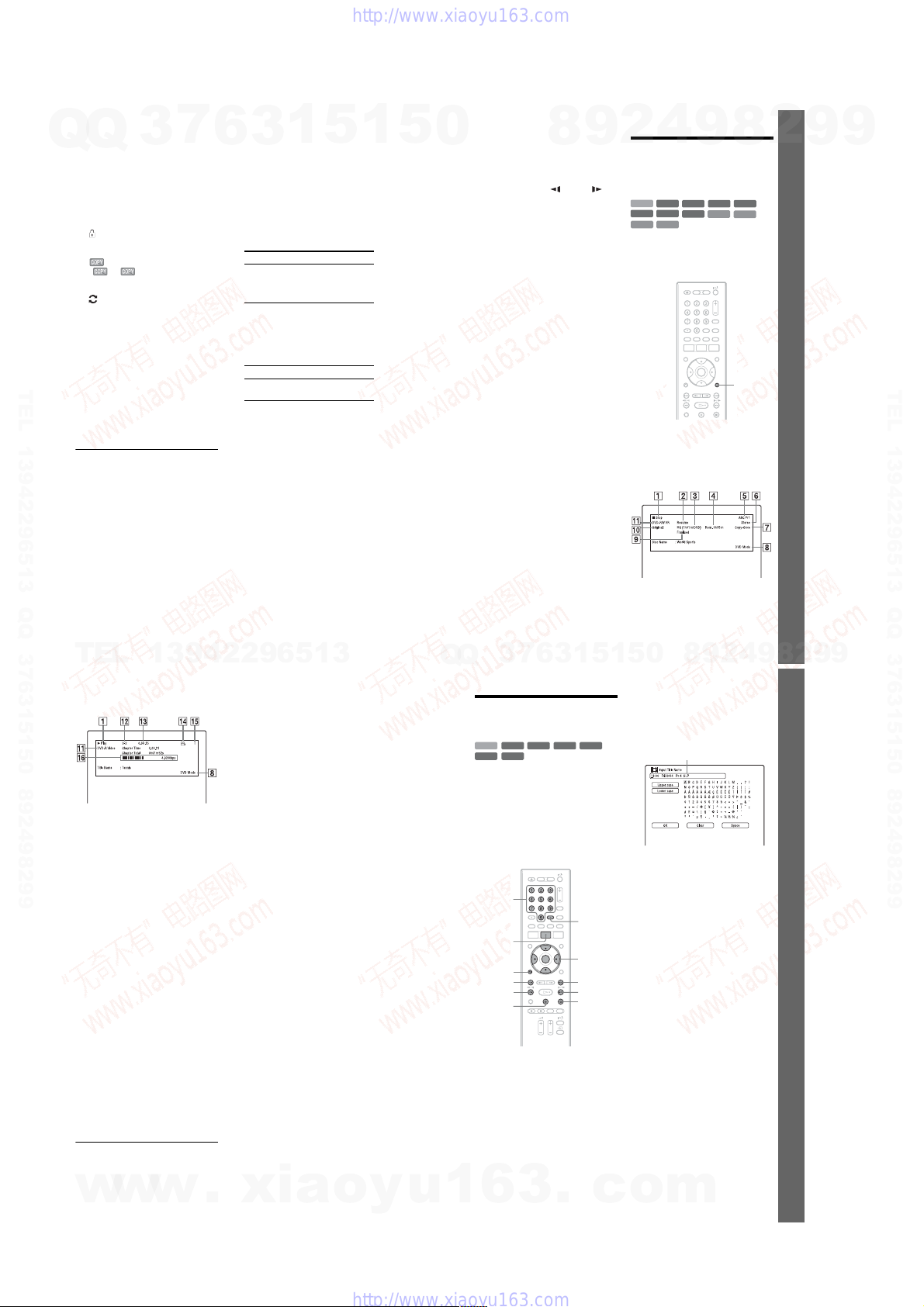
E Title information:
Q
Q
Displays the title number, title thumbn ail
picture (playback picture for the selected
title, still images for the other titles),
recording date, recorded station name (or
programme position numb er ), recording
mode, title name, and title size.
“Recording”: Indicates that the title is
currently being reco rded.
: Indicates protected title.
“NEW”: Indicates that the title is newly
recorded (not played back) (HDD only).
: Press DISPLAY to display
“ .” “” indicates titles
containing “Copy-Once” copy protection
signals (HDD only) (page 79).
: Indicates that the title is recorded
using the Update function.
Genre icons: Indicates the title’s genre
(HDD only).
F Remaining time of the current disc in
the current recording mode (example:
SP mode)
G Detailed information for the selected
TEL 13942296513 QQ 376315150 892498299
title
The resume point time is shown in the 8Title List.
3 Select a title using M/m, and press
ENTER.
Playback starts from the selected title.
To stop playback
Press x (stop).
To scroll the list display by page (Page
mode)
Press ./> while the Title List is
displayed. Each time you press .
the entire Title List changes to the next/
previous page of titles.
About the Title List for DVD-RWs/DVD-Rs
(VR mode)
You can switch the Title List to show
Original or Playlist titles.
1 Press < while the Title List is
displayed.
2 Select “Original” using M/m, and press
ENTER.
34
TEL
7
3
13942296513
3 Select “Original” or “Play List” using M/
6
3
m, and press ENTER.
To change the title order for HDD (Sort
Titles)
1 Press < while the Title List is
displayed.
2 Select “Sort Titles” using M/m, and press
ENTER.
3 Select the item using M/m, and press
ENTER.
Order Sorted
By Date In order of when the titles
Unseen Title In order of when the titles
By Title In alphabetical order.
By Number In order of recorded title
To search for a title by genre (HDD only)
1 Press < while the Title List is
displayed.
2 Select “Genre” using M/m, a nd press
ENTER.
3 Select a genre usi ng M/m, and press
ENTER.
To change a title thumbnail picture
(Thumbnail)
After recording, the first scene of the
/>,
recording (the title) is automatically set as the
thumbnail picture.
You can select a favourite sce n e for the
thumbnail picture shown in the Title List.
1 Press TITLE LIST.
For DVD-RWs/DVD-Rs (VR mode),
switch the Title Lists, if necessary.
2 Select a title, and press ,.
The sub-menu appears.
3 Select “Edit” using M/m, and press
ENTER.
1
5
were recorded. The title
that is recorded most
recently is listed at the top.
were recorded. The title
that is recorded most
recently and has not been
played is listed at the top.
Playlist titles are not
displayed.
number.
1
5
4 Select “Set Thumbnail” using M/m, and
0
Q
press ENTER.
The display for setting the thumbnail
point appears and the title starts to play.
5 While watchi ng the playback picture,
press H, X or cm/MC
to select the scene you want to set for a
thumbnail picture, and press X.
Playback pauses.
You can also select a scene us ing the
PLAY MODE button (page 69).
6 Select “OK” usin g M/m, and press
ENTER.
The scene is set for the title’s thumbnail
picture.
To return to the Title List, press
O RETURN.
To change the thumbnail preview mode
(Set Preview) (HDD only)
You can select “Quick Prev iew” or “Normal”
for the thumbnail preview mode in the Title
List. Set “Set Preview” in the “Options” setup
(page 128).
To turn off the Title List
Press TITLE LIST.
z Hint
You can select “Title List” from the System Menu.
b Notes
• The title names may not appear for DVDs created
on other DVD recorders.
• It may take a few sec onds for the thumbnail
pictures to be displayed.
• After editi ng, th e title thumbnail picture may
change to the first scene of the recording (title).
• After dubbing, the title th umbnail picture set on
the source recording is cancelled.
7
3
Q
8
6
3
9
1
4
2
4. Displaying the Playing
Time and Play
Information
+
HDD
RW
-
-
RVideo
RVR
DATA CD
DATA DVD
You can check the playing time of the current
title, chapter, track, or disc. Also, you can
check the disc name recorded on the DVD/
CD.
Press DISPLAY repeatedl y.
The displays differ depending on the disc
type or playing status.
In stop mode
Example: DVD-RW in VR mode
0
5
1
5
9
-
RWVR-RWVideo
DVD
VCD
9
8
8
2
+
R
CD
DISPLAY
,continued
9
4
2
Eight Basic Operations — Gettin g to Know Your DVD Recorder
35
8
9
2
9
9
TEL 13942296513 QQ 376315150 892498299
9
During playback
Example: DVD-R in Video mode
A Playing status
B Shows that the Resume Pl ay i s
available (page61).
C Current selected recording mode
(remaining DVD recording time/disc
type) (page 51)
D Remaining time
E Station name and programme position
number
F Audio setting for the current
programme
G Recording restrictions for the current
programme
H TV mode or DVD mode (page 22)
I Disc information
J Title type (Original or Playlist) for
DVD-RW/DVD-R in VR mode
K Disc type/format (page 9)
Displays the finalised disc in Video
mode as “DVD-Video.”
L Title number-Chapter number
(page 69)
M Playing time
N Multi-angles indicator (page 60)
O Copy-protect ed indicator (page 79)
P Data transfer bar and rate
z Hints
• When “On Screen Display” is set to “On”
(default) in the “Options” setup (page 127),
information automatically appears on the sc reen
when the recorder is operated.
• To increase disc space, see “To open up disc
space” (page 72).
b Note
Playing time of MP3 audio tracks may not be
displayed correctly.
5. Changing the Name of
a Recorded Programme
+
-
HDD
-
RVR
You can label a DVD, title, or programme by
entering characters. You ca n enter up to 64
characters for a title recorded in the HDD/
DVD-RW/DVD-R (VR mode), 40 characters
for a title recorded in the DVD+RW/DVDRW (Video mode)/DVD+R/DVD-R (Video
mode), but the actual number of ch aracters
displayed in the menus such as the Title List
will vary. The steps below explain how to
change the name of the recorded programme.
TITLE LIST
O RETURN
1 Press TITLE LIST.
2 Select a title, and press ,.
3 Select “Edit,” and press ENTER.
RWVR-RWVideo
RW
-
RVideo
Number
buttons
.
m
X
The sub-menu appears.
+
R
CLEAR
</M/m/,,
ENTER
>
M
x
4 Select “Title Name,” and press
ENTER.
The display for entering characters
appears.
The current name is displayed at the
input row.
Input row
5 Move the cursor to the point where you
want to insert the charact er using
m/M.
To erase all of the characters, press and
hold CLEAR for 2 seconds or more.
6 Select “Upper c ase” or “Lower case”
using ./>.
The characters for the selected t ype are
displayed.
The type of characters will change
according to the language you select in
“Easy Setup.”
7 Press </M/m/, to select the
character you want to enter, and press
ENTER.
The selected character appears at the
input row.
To insert a space, press X (or select
“Space,” and press ENTER).
8 Repeat steps 6 and 7 to enter the
remaining characters.
To erase a character, move the cursor to
the character at the inpu t r ow , and press
CLEAR (or select “Clear,” and press
ENTER).
To insert a character, move the cursor to
the right of the point where you wan t to
insert the character. Then select the
character, and press ENTER.
To erase all of the characters, press and
hold CLEAR for 2 seconds or more.
Eight Basic Operations — Gettin g to Know Your DVD Recorder
w
36
w
w
.
xia
o
y
u
1
6
3
1-8
.
c
o
m
,continued
37
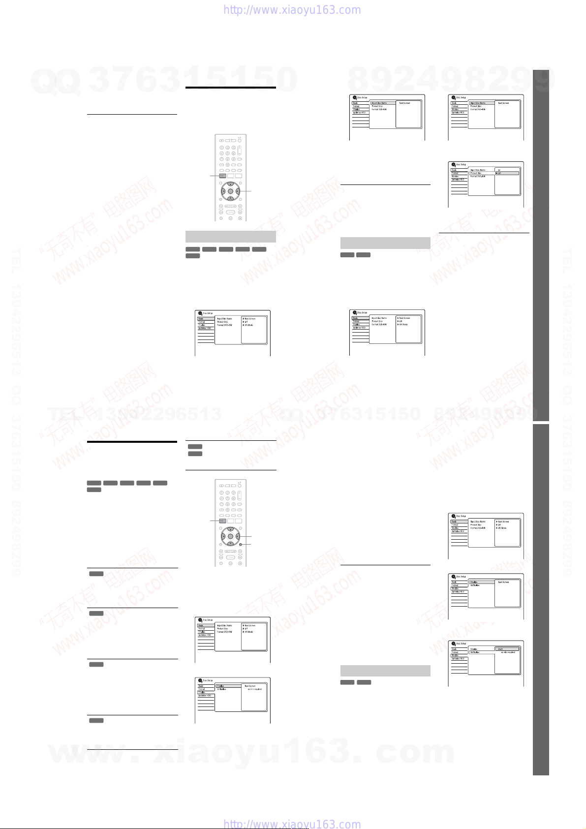
9 Press x (or select “OK,” and press
Q
Q
3
ENTER).
To cancel the setting, press
O RETURN.
To use the number buttons
You can also use the number buttons to enter
characters. Refer to the number next to each
row of letters on your TV screen .
1 In step 7 abov e, pr ess a number button
repeatedly to select a character.
Example:
Press the number 3 button once to enter
“D.”
Press the number 3 button three times to
enter “F.”
2 Press ENTER and select the next
character.
3 Press x (or select “OK,” and press
ENTER).
6
7
TEL 13942296513 QQ 376315150 892498299
1
3
5
6. Labelling and
Protecting a Disc
You can execute options effective for the
entire disc in the “Disc Setup” setup.
SYSTEM
MENU
Labelling a disc
+
-
RWVR-RWVideo
RW
-
RVideo
1 Insert a disc.
See “1. Inserting a Disc” on pag e 31.
2 Press SYSTEM MENU.
The System Menu appears.
3 Select “Disc Setup,” and press
ENTER.
1
+
R
5
</M/m/,,
ENTER
-
RVR
0
4 Select “Basic,” and press ENTER.
5 Select “Input Disc Name,” and press
6 Select “Next Screen,” and press
b Note
You can enter up to 64 characters for a DVD-RW/
DVD-R (VR mode) disc name, and 40 characters
for a DVD+RW/DVD-RW (Video mode)/DVD+R/
DVD-R (Video mode) disc name. The disc name
may not appear when the disc is played on other
DVD equipment.
-
1 Insert a disc.
2 Press SYSTEM MENU.
3 Select “Disc Setup,” and press
9
8
ENTER.
ENTER.
Enter the disc name (page37).
Protecting a disc
-
RVR
RWVR
See “1. Inserting a Disc” on pag e 31.
The System Menu appears.
ENTER.
2
4
4 Select “Basic,” and press ENTER.
9
5 Select “Protect Disc,” and pre ss
ENTER.
6 Select “On,” and press ENTER.
7 Press SYSTEM MENU to exit.
To cancel the protectio n
Select “Off” in step 6.
z Hint
You can set protection for individual titles
(page 72).
8
2
9
9
Eight Basic Operations — Gettin g to Know Your DVD Recorder
TEL 13942296513 QQ 376315150 892498299
TEL
w
w
38
13942296513
7. Playing the Disc on
Other DVD Equipment
(Finalise)
+
-
RWVR-RWVideo
RW
-
RVideo
Finalising is necess ary when you play discs
recorded with this recorder on other DVD
equipment.
When you finalise a DVD+RW, DVD-RW
(Video mode), DVD+R, or DVD-R (Video
mode), a DVD menu will be automatically
created, which can be displayed on other
DVD equipment.
Before finalising, check the differences
between the disc types in the table below.
Differences between disc types
Discs are automatically finalised
+
RW
when removed from the recorder.
However, you may need to finalise
the disc for certain DVD
equipment, or if the recording time
is short. You can edit or record on
the disc even after finalising.
Finalising is unnecessary when
-
RWVR
playing a disc on VR format
compatible equipment.
Even if your other DVD equipment
is VR format compatible, you may
need to finalise the disc, especially
if the recording time is short. You
can edit or record on the disc even
after finalising.
Finalising is necessary when
-
RWVideo
playing on any equipment other
than this recorder .
After finalising, you cannot edit or
record on the disc. If you want to
record on it again, unfinalise
(page 41 ) or reformat the disc
(page 42). However, if you
reformat the disc, all recorded
contents will be erased.
Finalising is necessary. The disc
-
RVR
can be played only on equipment
that supports DVD-R in VR mode.
After finalising you cannot edit or
record on the disc using this
recorder.
w
40
+
R
.
xia
-
RVR
Finalising is necessary when
+
R
playing on any equipment other
-
RVideo
than this recorder.
After finalising, you cannot edit or
record on the disc.
SYSTEM
MENU
</M/m/,,
ENTER
DISPLAY
1 Insert a disc.
See “1. Inserting a Disc” on pag e 31.
2 Press SYSTEM MENU.
The System Menu appears.
3 Select “Disc Setup,” and press
ENTER.
4 Select “Finalise,” and press ENTER.
5 Select “Finalise,” and press ENTER.
o
y
u
Q
Q
1
3
6
1
5
1
3
6
7
6 Select “Next Screen,” and press
ENTER.
For DVD-RW/DVD-R (VR mode), the
recorder starts finalising the disc. Go to
step 9.
7 (DVD+RW/DVD-RW (Video mode)/
DVD+R/DVD-R (Vi deo mode) only)
Select a title menu style, and press
ENTER.
The menu appears in the selected title
menu style when the “top menu” (or
“menu” for a DVD+RW/DVD+R) is
selected on the DVD equipment.
8 (DVD+RW/DVD-RW (Video mode)/
DVD+R/DVD-R (Vi deo mode) only)
Select “Yes,” and press ENTER.
The recorder starts finalis i ng the disc.
9 Press SYSTEM MENU to exit.
z Hint
You can check whether the disc has been finalised
or not. Press DISPLAY after step 1 (page 35).
b Notes
• Depending on the condition of the dis c,
recording, or the DVD equipment, discs may not
play even if the discs are finalised.
• The recorder may not be able to fi nal ise the disc
if it was recorded on another recorder.
• Inserting an unfinalised disc into other DVD
equipment may damage the recorded contents.
• When using a DVD+RW, you can edit or record
on the disc even after finalising. However, the
title menu will not be displayed. Finalise the disc
again to display the title menu.
Unfinalising a disc
-
RWVR-RWVideo
For DVD-RWs (Video mode )
DVD-RWs (Video mode) that have been
finalised to prohibit additional recordin g or
editing can be unfinalised to allow further
recording or editing.
For DVD-RWs (VR mode)
If you cannot record or edit on a DVD -RW
(VR mode) that has been finalised with other
DVD equipment, unfinalise the disc.
3
.
c
0
5
o
9
4
2
9
8
b Note
The recorder is not able to unfinalise DVD-RWs
(Video mode) that have been finalised on another
recorder.
1 Insert a disc.
See “1. Inserting a Disc” on page31.
2 Press SYSTEM MENU.
The System Menu appears.
3 Select “Disc Setup,” and press
ENTER.
4 Select “Finalise,” and press ENTER.
5 Select “Unfinalise,” and press
ENTER.
6 Select “Start,” and press ENTER.
The recorder starts unfinalisi ng the disc.
Unfinalising may take several minutes.
m
8
2
9
9
39
Eight Basic Operations — Gettin g to Know Your DVD Recorder
41
1-9
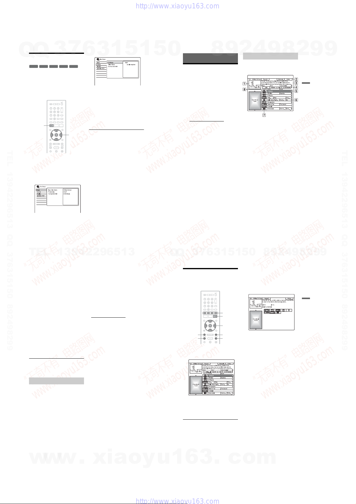
7
-
RWVR-RWVideo
MENU
3
-
RVR-RVideo
</M/m/,,
ENTER
Q
Q
8. Reformatting a Disc
+
RW
New discs are automatically formatted when
inserted. If necessary, you can manually reformat a DVD+RW, DVD-RW, or DVD-R
disc to make a blank disc. For DVD-R Ws or
DVD-Rs, you can select a reco rd i ng format
(VR mode or Video mode) according to your
needs.
SYSTEM
TEL 13942296513 QQ 376315150 892498299
1 Insert a disc.
See “1. Inserting a Disc” on page 31.
2 Press SYSTEM MENU.
The System Menu appears.
3 Select “Disc Setup,” and press
ENTER.
42
TEL
13942296513
4 Select “Format,” and press ENTER.
6
5 Select an item, and press ENTER.
6 Select “Start,” and press ENTER.
z Hint
By reformatting, you can change the recording
format on DVD-RWs, or record again on DVDRWs that have been finalised.
1
3
“VR Mode”: Formats DVD-RWs/DVDRs (VR mode or unrecorded discs) in VR
mode.
“Video Mode”: Formats DVD-RWs/
DVD-Rs in Video mode.
“Format DVD+RW”: Formats
DVD+RWs.
All contents on the disc are eras ed.
5
1
5
0
GUIDE Plus+
Introduction to the
GUIDE Plus+ System
The GUIDE Plus+® system is a free
interactive programme guide. It displays up
to seven days of programme list i ngs,
including programme titles, promotions, and
broadcast information. GUIDE Plus+ data for
the television programme listings are ca rri ed
by your local broadc ast host channel and are
received through your aer ia l, set top box
receiver, or direct cable connection from the
wall.
Visit www.europe.g uideplus .com
all European host channels.
These are just a few of the ways to use the
GUIDE Plus+ system.
–Search for programmes by listing them
according to category (such as Movies or
Sport) or by using the Keyword Search
function (page46).
–Once you have found th e pr ogramme you
are looking for, use the GUID E Pl us+
system to set the timer for recording
(page 53).
–You can set the system t o display your
favourite programmes according to
conditions that you set, such as category
and keyword (page 47).
For more information, see “Watching TV
Using the GUIDE Plus+ System” (page 45).
7
3
Q
Q
8
6
3
9
for a list of
1
4
2
Learning the common elements
Press GUIDE.
The GUIDE Plus+ system “Home Screen”
appears.
A Video Window: This shows the
programme you were watching when
you pressed GUIDE.
B Action Bar: When the same colour
button on the remote is pressed, the
Action Bar functions. The Action Bar
function differs according to the
screen.
C Information Box: Shows information
about the selected programme when
the “Home Screen” is displayed.
Contents will differ according to the
displayed screen.
D Menu Bar: Press the blue button
(“Home”), and press M to move the
cursor to the Menu Bar. Then select
one of the following features using </
,, and press ENTER.
“Grid”: Shows the programmes for the
current time slot and next 7 days.
“Search”: Allows you to search for
titles by category or by keyword
(page 46). The displayed category
depends upon the programme data
received by this recorder. Movies,
Sport, and Children are examples of
possible categories.
“My TV”: Sets the profile for your
favourite programmes (page 47).
“Schedule”: Displays the list of timer
settings (page 57).
0
5
1
5
9
8
9
8
2
,continued
9
4
2
GUIDE Plus+
43
8
9
2
9
9
TEL 13942296513 QQ 376315150 892498299
9
“Info”: Shows information when
available.
“Editor”: Allows you to edit the
channel lineup and channel display
(page 49).
“Setup”: Allows you to change the
language, country/region, postal code,
input source, or host channel.
E “Home” position: When you press the
blue button (“Home”), the cursor
returns to the last programme position
on the “Grid.”
F Tiles: Shows the programme titles and
category; green (sports), purple
(movies), blue (children’s), teal
(others).
G Broadcast station Logo: Shows the
broadcast station logo.
H Time Slot: Indicates the currently
selected time slot. Use </, to select
a different time slot.
z Hint
You can also move the cursor to the Menu Bar by
pressing MENU.
Troubleshooting guide
If you are having trouble displaying the
television programme list, please check th e
following:
• Your country/region must be set correctly
(page 23).
• The clock must be set correctly. If the clock
is not set, set it manually (page109).
• This recorder downloads the GUIDE Plus+
data several times a day when the recorder
is turned off (standby mode). Turn off the
recorder when you are not us in g it (f or
example, at night). After initial setup
(page 23), it may take up to 24 hours for
your recorder to start re ceiv ing prog ra mme
listings. It may take up to one day to receive
all seven days of TV programme lis ti ngs.
• Check the following if the programme
guide data has not been received after
waiting for a day:
–“Easy Setup” (page 23) is completed.
–The host channel is not disabled (see
“Disabling programme positions” on
page 50).
–The timer is not set.
If the programme guide data still cannot be
received after checking the above, search
for the host channel at the following
website and set the host channel manually
(page 49):
www.europe.guideplus.com
• If the host channel has changed or moved,
the programme guide data can not be
received. In this case, follow the steps in
“Searching for the GUIDE Plus+ host
channel” (page 48) to update t he host
channel setting.
• If the set top box receiver is connected to
the recorder using a SCART co rd only, do
the following:
–Turn on your set top box receiver.
–Connect the set top box c ont r oller.
–Follow the steps in “Changing the GUI DE
Plus+ host channel manua ll y” (page 49)
to set the host channel manually. Be sure
to set your set top box receiver (tuner) as
the source.
b Notes
• Your set top box receiver’s programme position
may suddenly change even if the recorder is
turned off. This is because the set top box
controller has changed the programme position to
receive the GUIDE Plus+ data.
• When you reset the recorder (page 136) the
following GUIDE Plus+ system settings are reset:
– Country/region setting in “Easy Setup”
–“Country” of “Setup” - “Basic Setup” in the
Menu Bar
–“Postal Code” of “Setup” - “Basic Setup” in the
Menu Bar
Note that the GUIDE Plus+ system is also reset
when you make changes to the host channel
settings.
• The GUIDE Plus+ system cannot be used when
“Input Line System” is set to “NTSC” in the
“Basic” setup (page 110).
Watching TV Using the
GUIDE Plus+ System
Colour
buttons
GUIDE
</M/m/,,
ENTER
PAGE –
DAY –
1 Press GUIDE.
The GUIDE Plus+ system “Home
Screen” appears.
2 Select a programm e using </M/m/
,, and press ENTER.
The GUIDE Plus+ system disappears and
the programme position changes to the
selected programme.
PAGE +
DAY +
To select a programme positio n quickly
using the TV broadcast station l ogo
1 Press GUIDE.
The GUIDE Plus+ system “Home
Screen” appears.
2 Press the yellow button (“Channels”).
3 Select the TV br oadcast station logo
using </M/m/,, and press ENTER.
The display returns to “Grid” and the
programme currently being broadcast by
the selected TV station is selected.
4 Select a programme using </,, and
press ENTER.
To return to the “Home” position
Press the blue button (“Home”).
The cursor returns to the home position on the
“Grid.”
To set a programme for timer recording
See “One Button Recording (GUIDE Plus+)”
(page 53).
To close the GUIDE Plus+ system
Press GUIDE.
z Hints
• Press the PAGE +/– buttons to change the
programme list by page.
• Press the DAY +/– buttons to change the
programme list by day.
GUIDE Plus+
w
44
w
w
.
xia
o
y
u
1
6
3
1-10
.
c
o
m
,continued
45

Q
Q
7
3
The Video Window is locked s o th at it does
not change programme posi tions when you
move the cursor across other titles.
From “Grid,” select the logo of the
programme position that is locked, and pr ess
the red button (“Unlock”). “” changes to
“” and the Video Window is unlocked. To
lock the Video Window, select the logo of the
programme position you wa n t t o l ock and
press the red button (“Lock”).
b Notes
• The Video Window is locked during recording
and the lock indicator appears in the Video
Window. You cannot unlock the Video Window
while recording.
• If you are watching programmes through a set top
box receiver, the Video Window may not change
as fast as you move the cursor. In this case, lock
the Video Window (page 46).
6
1
3
5
Searching for a
Programme Using the
GUIDE Plus+ System
1 Select “Search” in the Menu Bar, and
press ENTER.
1
5
Colour
buttons
</M/m/,,
ENTER
0
To unlock the Video Window
TEL 13942296513 QQ 376315150 892498299
2 Select a category using </,.
To search for a programme by keyword,
select “My Choice.” You can search for
all programmes that contain the keyword
in the programme’s title and in the
programme’s Information Box. If no
keywords are displayed, enter the
keyword. See “To enter a new keyword”
below.
3 Select a sub-category using M/m, and
press ENTER.
Programmes that meet the conditions are
listed.
The sub-categories differ according to
country/region.
TEL
46
13942296513
Q
Q
3
7
4 Select a programm e using M/m, and
To enter a new keyword
1 Select “Search” in the Menu Bar, and
2 Select “My Choice” using </,.
3 Press the yellow button (“Add”).
4 Select a character on the keyboard using
5 Repeat step 4 to enter the keyword.
6 Press the green button (“Save”).
To set a programme for timer recording
See “One Button Recording (GUIDE Plus+)”
(page 53).
z Hint
When two or more keywords are set for “My
Choice,” you can select “All” for sub-category.
6
9
8
press ENTER.
press ENTER.
The display for entering characters
appears.
</M/m/,, and press ENTER.
To switch between upper-ca se, lowercase, or characters with accents, press the
yellow button (“Keyboard”) repeatedly.
To cancel entering a new keyword, press
the red button (“Back”).
The entered keyword is regist er ed.
To delete the keyword, select the
keyword you want to delete, and press
the red button (“Delete”).
To change the keyword, select the
keyword you want to change, and press
the green button (“Edit”).
5
1
3
2
1
5
4
0
2
9
8
9
Colour
buttons
</M/m/,,
ENTER
,continued
2
8
9
Listing Up Your Favourite
Programme Information
(My TV)
You can set a profile and list up only your
favourite programme information.
Setting a profile
1 Select “My TV” in the Menu Bar, and
press the yellow button (“Profile”).
4
2
9
8
9
9
47
9
GUIDE Plus+
TEL 13942296513 QQ 376315150 892498299
w
w
2 Select “Channels,” “Categories,” or
“Keywords,” and press the yellow
button (“Add”).
“Channels”: Select the programme
position using </M/m/,, and press
ENTER. To add more programme
positions, press the yellow button
(“Add”). You can register up to 16
programme positions.
To cancel the registrat io n , select a
programme position, and press the red
button (“Delete”).
“Categories”: Select the category using
</M/m/,, and press ENTER. To add
more categories, press the yellow button
(“Add”). You can register up to 4
categories.
To cancel the registrat io n , select a
category, and press the red button
(“Delete”).
“Keywords”: Enter a keyword . See “To
enter a new keyword” on page 47. To add
more keywords, press the ye llow button
(“Add”). You can register up to 16
keywords.
To cancel the registrat io n , select a
keyword, and press the red button
(“Delete”).
3 Press ENTER.
To change the profile settings
Repeat from step 1 above.
Selecting and watching a
programme from My TV
1 Select “My TV” in the Menu Bar, an d
press ENTER.
The programmes that match the profile
conditions are displayed.
2 Select a programme using </M/m/
,, and press ENTER.
To set a programme for timer recording
See “One Button Recording (GUIDE Plus+)”
(page 53).
48
w
.
Making Changes to the
GUIDE Plus+ System
Number
buttons
Searching for the GUIDE Plus+
host channel
The default host channel setting is set to
“Automatic,” so you should not have to
change the host channel setting. However, if
the host channel has changed or m oved,
update the host channel setti ng.
If the set top box receiver is connect ed to th e
recorder using a SCART cord only (page 14),
see “Changing the GUIDE Plus+ host
channel manually” on page 49.
1 Select “Setup” in the Menu Bar.
The GUIDE Plus+ setup menu ap pears.
2 Select “Host Channel Setup” using M/
m, and press ENTER.
3 Press the yellow button (“Reset”).
4 Press [/1 to turn off the recorder.
xia
o
y
[/1
Colour
buttons
GUIDE
</M/m/,,
ENTER
u
1
6
5 Wait for one day unti l the programme
guide data can be received.
If the programme guide data has not been
received after waiting for a day, search
for the host channel at the following
website and set the host channel
manually (“Changing the GUIDE Plus+
host channel manually” (page49)).
www.europe.guideplus.com
Changing the GUIDE Plus+ host
channel manually
If the set top box receiver is connect ed to th e
recorder using a SCART cord only and you
want to receive the programme gu id e data
from your set top box receiver, search for the
host channel on the following website and set
it for your area, following the steps below:
www.europe.guideplus.com
1 Select “Setup” in the Menu Bar.
The GUIDE Plus+ setup menu ap pears.
2 Select “Host Channel Setup” using M/
m, and press ENTER.
3 Press the yello w button (“Change”)
twice.
“Manual” appears.
4 Select “Source” using ,.
5 Press the yello w button (“Source”)
repeatedly to select the input source.
6 Select “Prog. No.” using ,.
7 Enter the programme positi on number
using the number buttons.
8 Press the green button (“Save”).
The display asks for confirmation.
3
.
c
o
9 Select “Confirm” using </,, and
press ENTER.
The display returns to the GUIDE Plus+
setup menu.
10
Wait one day until the programm e
guide data can be received.
To cancel the settings
Press the red button (“Back”).
To return to the “Home” position
Press the blue button (“Home”).
The cursor returns to the home position on the
“Grid.”
To check the GUIDE Plus+ syste m
information
1 Select “Setup” in the Menu Bar, and
press ENTER.
2 Select “GUIDE Plus+ system
Information” using M/m, and press
ENTER.
Checking programme positions
Check whether programme position numbers
are the same as the programme position
numbers set in the “Tuner” setup.
If you want to make adjustments to the
channel settings or change the channel name,
see “Aerial Reception Settings (Tuner)”
(page 111).
1 Select “Editor” in the Menu Bar.
2 Press ENTER.
3 Press , to move the cursor to the
right column.
m
,continued
GUIDE Plus+
49
1-11
4 Select the programme position you
Q
Q
want to check using M/m.
To change the programme position, press
the green button (“Prog. No.”), then enter
a programme position num ber using the
number buttons, and pr ess ENTER.
b Note
To receive from the recorder a program me posit ion
that can be received by either the set top box
receiver or the recorder, change the input source in
step 4.
Disabling programme positions
If any programme positions are unused or
contain unwanted channels, you can hide
them.
1 Select “Editor” in the Menu Bar, and
press ENTER.
2 In the left column, select the
programme position you wan t to hide
TEL 13942296513 QQ 376315150 892498299
or display using M/m.
3 Press the red butto n (“On/Off”).
The disabled positions will turn grey.
To show the disabled positions, press the
red button (“On/Off”) again.
b Notes
• You cannot record a prog ram me position if it is
not set in “Aerial Reception Settings (Tuner)”
(page 111) even if it is set to “On” in the “Editor”
in the Menu Bar.
• If you are using your set top box rec ei ve r to
receive programmes (when the set top box
receiver is connected to the recorder using a
SCART cord only, page 14) and are able to
receive the same programme with both the set top
box receiver and the recorder, change the
“Source” to receive the progra mme with the
recorder’s tuner.
3
7
6
3
1
5
1
5
0
Timer Recording
Before Recording
Before you start recording…
• Check that the disc has en ough available
space for the record ing (page 35). For the
HDD, DVD+RWs, and DVD-RWs, you
can free up disc space by erasing titles
(page 72).
• Adjust the recording picture quality if
necessary (page56).
b Note
To play a recorded disc on other DVD equipment,
finalise the disc (page 40).
Recording mode
Like the standard ×3 recording modes of
video tapes, you can select the desired
recording mode using the REC MODE
button.
Recording modes with higher quality provide
a more beautiful recording, but the l arge data
volume also results in a shorter recording
time.
Conversely, a longer duration provi des a
longer recording time, but the lower data
volume results in a coarser picture quality.
Press REC MODE repeate dly to switch the
recording modes.
To select further options for recording mode
(manual recording mode), set “Manual Rec.
Mode” to “On (go to setup)” in the
“Recording” setup (page 119). To re cor d
pictures in higher quality than HQ m ode on
the HDD, set “Manual Rec. M ode” to “On
(go to setup),” and then select “HQ+.” For
details about manual recording mode, see
page 119.
For timer recording, you can also select
“AUTO” as recording mode, w hich
maximizes the recording quality for t he space
available on the disc (if recor di ng to DVD),
or to fit onto a blank disc (if recordi ng to
HDD).
8
9
4
2
Recording
mode
HQ (High
quality)
HSP R 50 79 1hr.
SP (Standard
mode)
LSP r 84 130 2 hr.
ESP r 100 155 3
LP r 135 210 4
EP r 200 315 6
SLP r 270 425 8
SEP
duration)
*1
*2
z Hint
To easily select a manual recording mode, press
REC MODE repeatedly to display “MN,” and
select a manual recording mode using </ ,.
Approx. recording time
(hours)
RDRHX750
34 53 1hr.
68 105 2
*2
(Long
340 530 10
The approximate recording time is for 12 cm
DVD discs.
The approximate recording times for DVD+R
DL (Double Layer)/DVD-R DL (Dual Layer)
discs are as follows:
HQ: 1 hour 51 minutes
HSP: 2 hours 41 minutes
SP: 3 hours 35 minutes
LSP: 4 hours 29 minutes
ESP: 5 hours 23 minutes
LP: 7 hours 11 minutes
EP: 10 hours 46 minutes
: 14 hours 21 minut es
SLP
SEP: 17 hours 57 minutes
When recording to DVD+RW or DVD+R, SLP
is the longest recording time available. If you
select SEP, the recording mode will
automatically revert to SLP.
9
HDD
RDRHX950
8
DVD
1min.
30 min.
30 min.
2
*1
Timer Recording
9
9
TEL 13942296513 QQ 376315150 892498299
50
TEL
b Notes
• The maximum cont inuous recording time to the
HDD is 12 hours for a single title. A title longer
than 12 hours is divided.
• Situations below may cause slight inaccuracies
with the recording time.
– Recording a programme with poor reception, or
a programme or video source of low picture
quality.
– Recording on a disc that has already been
edited.
– Recording only a still picture or just sound.
• Programmes are recorded in the following aspect
ratio.
– In the original aspect ratio, when recording to
the HDD (when “HDD Recording Format” is
set to “Video Mode Off” in the “Recording”
setup (page 122))/DVD-RWs/DVD-Rs (VR
mode).
– In 4:3, when recording to DVD+RWs/
DVD+Rs.
• When recording to DVD-R DLs (Video mode),
the title is divided when the layer switches.
Recording stereo and bilingual
programmes
The recorder automatica lly receives and
records stereo and bilingual programmes
based on the ZWEITON system or the
NICAM system.
The HDD (when “HDD Recording Format”
is set to “Video Mode Off” in the
“Recording” setup (page 122)) and a DVDRW (VR mode) and DVD-R (VR mode) can
record both main and sub sounds. You can
switch between main and sub when playing
the disc.
The HDD (when “HDD Recording Format”
is set to “Video Mode On” in the “Recording”
setup (page 122)) and a DVD+RW, DVD+R,
DVD-RW (Video mode), or DVD-R (Video
mode) can record only one sound track (main
or sub) at a time. Select the sound trac k in the
“Audio In” setup before recording starts. Set
“Bilingual Reco rding” to “A/L” (default) or
“B/R” in the “Audio In” setup (page 116).
About HDD Recording format, see page 122.
w
52
13942296513
w
w
ZWEITON (German stereo) syste m
When a stereo-based prog ramme is re ceived ,
“Stereo” appears.
When a bilingual ZWEITON-based
programme is received, “L,” “R,” or “L+R”
appears.
NICAM system
To record a NICAM programme, be sur e t o
set “NICAM Select” to “NICAM” (default)
in the “Audio In” setup. If the sound is not
clear when listening to NICAM broadcasts,
set “NICAM Select” to “Standard”
(page 116).
z Hint
You can select the audio (main or sub) while
recording bilingual programmes using the AUDIO
button. This does not affect the recorded sound.
Unrecordable pictures
Pictures with copy protection cannot be
recorded on this recorder .
Copy control
signals
Copy-Free
Copy-Once
Copy-Never None
* The recorded disc can be played only on CPRM
compatible equipment (page 9).
.
Recordable discs
HDD
-
RWVideo
-
RVideo
HDD
-
RWVR
-
RVR
xia
+
RW
+
R
(CPRM*)
(CPRM*)
-
RWVR
-
RVR
o
y
u
7
3
Q
Q
Timer Recording (GUIDE
Plus+/Manual)
+
-
z REC
x REC
STOP
-
RW
RVideo
RWVR-RWVideo
3
HDD
-
RVR
There are two methods to set the timer within
the GUIDE Plus+ system: One Button
Recording and setting the timer manually.
You can set the timer for a total of 32
programmes (8 programme s w hen using the
VPS/PDC function), up to 30 days in
advance.
b Notes
• When the recorder is conne ct e d to a set top box
receiver and you want to record using the GUIDE
Plus+ system, turn on the set top box receiver and
connect the set top box controlle r.
• Do not operate your set top box receiver just
before or during a timer recording. This may
prevent the accurate recording of a programme.
One Button Recording (GUIDE
Plus+)
You can use the GUIDE Plus+ system to set
the timer to record a programme up to seven
days in advance.
1
6
6
3
.
1
Colour
buttons
GUIDE
</M/m/,
0
5
1
5
1 Press GUIDE.
+
R
2 Select a programme usin g </M/m/
,.
To search for a programme by category
or by keyword, select “Search” in the
Menu Bar. See “Searching for a
Programme Using the GUIDE Plus+
System” on page 46 for more
information about searching for a
programme.
You can select a programm e from “My
TV” (page 47).
3 Press the red button (“Record”) or
z REC.
The set programme and Time Slot
change colour and the recorder is ready
to start recording. When recording f rom a
set top box receiver, be sure to turn it on.
Unlike a VCR, there is no need to tur n off
the recorder before the timer recording
starts.
• To record on a DVD
See “Checking/Changing/Cancelling
Timer Settings” on page 57.
• To make more detailed timer settings
See “Checking/Changing/Cancelling
Timer Settings” on page 57.
To confirm, change, or canc el a timer
recording
See “Checking/Changing/Cancelling Timer
Settings” on page 57.
To stop recording during timer recording
Press x REC STOP.
Note that it may take a few seconds for the
recorder to stop record i ng.
On-screen instructions may appear after
pressing x REC STOP. In this case, follow
the on-screen instructions .
c
o
m
8
9
2
,continued
9
4
,continued
51
8
53
9
9
2
Timer Recording
1-12

Rec. Mode Adjust
7
Q
Q
TEL 13942296513 QQ 376315150 892498299
3
If there is not enough available disc space for
the recording, the recorder automatically
adjusts the recording mode t o enable the
entire programme to be recorded. Set “Rec.
Mode Adjust” to “On” in the “Recording”
setup (page 121).
If the timer settings overlap
If one or more timer settings overlap, a
message appears. To change the timer
settings, see “Checking/Changing/
Cancelling Timer Settings” on page 57.
z Hint
If you are recording to the HDD, you can play the
title as it is being recorded by sele cting the
programme title on the Title List (page 68).
b Notes
• If a message indicating that the HDD is full
appears on the screen, change the recording
destination to “DVD,” or make available space
for the recording (page72).
• If there is not enough available DVD disc space
for the recording, the recorder automatically
records the programme to the HDD even if you
select “DVD” (Recovery Recording).
• The last recording mode you se le c te d ma nua lly
becomes the default recording mode for timer
recordings made from the GUIDE Plus+ system.
• You cannot adjust the recording quality (HDD or
DVD) once the recording starts.
• The beginning of some rec or dings may not be
made when using the VPS/PDC function.
• You cannot extend the rec or ding duration time
VPS/PDC” is selected (page 58).
when “
• The “Rec. Mode Adjust” function only works
with a timer recording to DVD, and the VPS/PDC
function set to off.
• The recording mode cannot be set to “AUTO”
when “VPS/PDC” is set to “On.”
6
1
3
5
Setting the timer manually
Number
buttons
z REC
x REC
STOP
1 Press GUIDE.
2 Select “Schedule” in the Menu bar.
The SCHEDULE list appears.
3 Press the green button (“Manual”).
4 Set the date using the numbe r buttons
and </M/m/,. Then press th e
green button (“Next”).
5 Set the start time using the number
buttons and </M/m/,. Then press
the green button (“Next”).
6 Set the stop time using the number
buttons and </M/m/,. Then press
the green button (“Next”).
1
5
Colour
buttons
GUIDE
</M/m/,,
ENTER
0
7 Select the inpu t source using M/m,
8 Press the green button (“Next”).
9 Press the green button (“Save”).
To confirm, change, or can cel a timer
recording
See “Checking/Changing/Cancelling Timer
Settings” on page 57.
To stop recording during timer recording
Press x REC STOP.
Note that it may take a few seconds for the
recorder to stop recording.
On-screen instruction s m ay appear after
pressing x REC STOP. In this case, follow
the on-screen instructions.
Rec. Mode Adjust
If there is not enough available disc space for
the recording, the recorder automatically
adjusts the recording mode to enable the
entire programme to be recor ded. Set “Rec.
Mode Adjust” to “On” in the “Recording”
setup (page 121).
9
8
and select the programme positio n
using the number buttons or M/m.
You can also select the prog ramme
position using the yellow button
(“Channels”).
The display for entering characters
appears.
To change the title name, select a
character on the keyboard using </M/
m/,, and press ENTER.
To switch between upper-ca se, lowercase, or characters with accents, press the
yellow button (“Keyboard”).
The date, start and stop times,
programme position, etc. settings appear.
The recorder is ready to start r ecording.
2
4
2
8
9
Using the Quick Timer function
You can set the recorder to record in 30minute increments.
Press z REC repeatedly to set the
duration.
Each press advances the time in 30-minute
increments. The maximum duration is six
hours.
(normal recording)
The time counter decreases minute by minute
to 0:00, then the recorder stops recording (the
power turns off).
To cancel the Quick Timer
Press z REC repeatedly until the counter
appears in the front panel display. The
recorder returns to nor m al recording mode.
To stop recording, press x REC STOP.
b Note
If you turn off the recorder during recording,
recording is stopped.
9
9
Timer Recording
TEL 13942296513 QQ 376315150 892498299
TEL
54
13942296513
Adjusting the recording picture
quality
You can adjust the picture quality from the
connected equipment, such as a TV or V CR
by selecting a preset set t ing. You can also
adjust the picture quality by ch anging
detailed settings, and store up to three settings
in the memory.
SYSTEM
MENU
</M/m/,,
ENTER
DISPLAY
1 Press SYSTEM MENU in stop mode.
The System Menu appears.
2 Select “Picture Adjustment,” and
press ENTER.
3 Select a preset setting, and press
ENTER.
“Tuner”: TV broadcasts
“VCR”: Video cassettes
“DTV”: Digital broadcasts
“Memory1”/“Memory2”/“Memory3”:
Your own settings. To create your own
settings, see “To create your own setting”
on page 56.
To check the detailed settings for the
selected preset, press DISPLAY.
4 Press SYSTEM MEN U to exit.
To create your own setting
1 Select “Memory1,” “Memory2,” or
“Memory3” in step 3.
2 Select “Detailed Settings,” and press
ENTER.
The display for adjusting detailed
settings appears.
3 Select an item using M/m, and adjust
settings using </,.
For details about each setting, see the
explanation of the display.
“Prog. Motion”: Adjusts the progressive
video signal when “Component Video
Out” is set to “Progressive” (page 115).
Select “Motion” for a picture, including
subjects that move dynamically.
Select “Still” for a picture with little
movement.
“Cinema”: Converts the progressive
video signal to match the type of DVD
software that you are watching when
“Component Video Out” is set to
“Progressive” (page 115).
Select “Auto” to detect the software ty pe
(Film-based or Video-based )
automatically and select the appropria te
conversion mode. Normally select this
position.
Select “Off” to fix the conversion mode
to the mode for Video-based software.
“3-D Y/C”: Adjusts the brightness/
colour separation for the video signals.
Select “Motion” for a picture, including
subjects that move dynamically.
Select “Still” for a picture with little
movement.
“YNR” (luminance noise reduct i on):
Reduces noise contained in t he
luminance element of the vide o si gnal.
“CNR” (chroma noise reduction):
Reduces noise contained in t he chroma
element of the video signal.
“Detail”: Adjusts the sharpness of
images outlines.
“White AGC”: Turn on for automatic
white level adjustment.
“White Enhancer”: Adjusts the intensity
of white.
“Black Enhancer”: Adjusts the intensity
of black.
Q
Q
1
3
6
7
3
“Black Level”: Selects the black level
(setup level) for the NTSC video signals.
Select “ON” to raise the standar d bl ack
level. Select this when the picture
appears too dark.
Select “OFF” to set the black level of the
input signals to the standard level.
Normally, select this position.
“Hue”: Adjusts the colour balance .
“Chroma Level”: Makes the colours
deeper or lighter.
4 Press SYSTEM MENU to exit.
The setting is automatically stored as the
setting you selected in step 1.
Creating chapters in a title
The recorder can automatic al ly divide a
recording (a title) into chapters by inserting
chapter marks. To sele ct chapter mark
intervals or disable this func ti on, see “Auto
Chapter (HDD/VR),” “Auto Chapter
(Video),” or “Auto Chapter (DVD+R/+RW)”
in the “Recording” setup (page 121).
When recording to the HDD, a DVD-R (VR
mode) or a DVD-RW (VR mode), you can
edit chapter marks (p age 75).
5
1
5
0
,continued
2
8
9
4
2
9
8
Checking/Changing/
Cancelling Timer
Settings
+
-
HDD
-
RVR
You can change or cancel timer settings using
the SCHEDULE list.
Changing timer settings
1 Press GUIDE.
2 Select “Schedule” in the Menu bar.
RWVR-RWVideo
RW
-
RVideo
Number
buttons
The SCHEDULE list appears.
Colour
buttons
GUIDE
</M/m/,
55
9
9
+
R
Timer Recording
w
w
56
w
.
xia
o
y
u
1
6
3
1-13
.
c
o
m
,continued
57
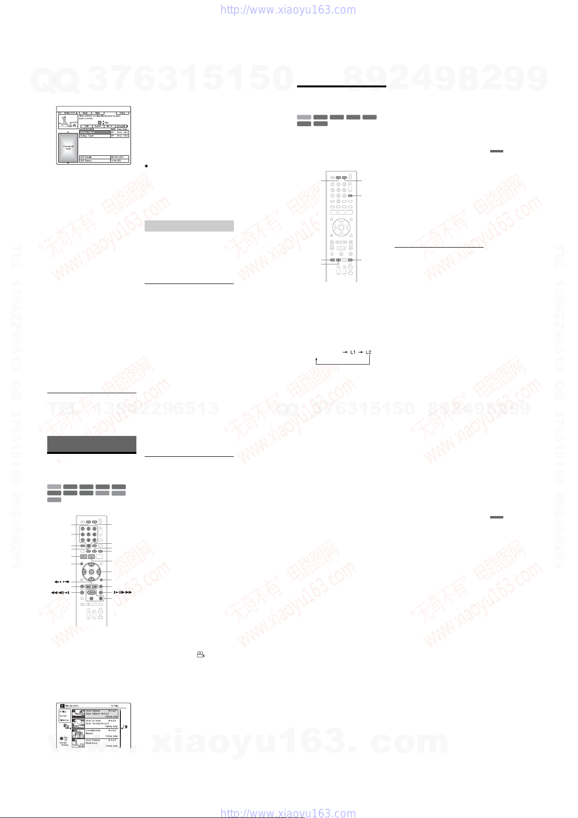
3 Select the timer setting you want to
Q
Q
change using M/m, and press the
green button (“Edit”).
4 In the left column, select an item
using the red button (“Back”) or the
green button (“Next”), and adjust
using the number buttons o r </M/m/
,.
You can change the date, start time, stop
time, programme position, or input
source.
The cursor moves to the right column.
5 Press the corresponding colour button
TEL 13942296513 QQ 376315150 892498299
repeatedly to change se ttings.
• Yellow button (“Destination”): Sets the
recording destination. If there is not
enough available DVD disc spa ce f o r
the recording, the recorder
automatically records the programme
to the HDD even if you select “DVD”
(Recovery Recordi ng ). When y ou s et a
daily or weekly timer, “HDDr” allows
you to replace the previous timer
recording with the new one
automatically (HDD only).
• Green button (“Frequency”): Selects
the recording pattern .
• Red button (“Quality”): Selects the
recording mode (page 51).
3
7
6 Press , to display “Timing.”
7 Press the green button (“Timing”)
repeatedly to select the duration time
or to set the VPS/PDC function.
See “About the VPS/PDC function”
below.
• If you want to record to a particular
HDD genre, press the yellow button
(“Genre”) repeatedly.
58
TEL
13942296513
b Notes
6
• The new settings become effective when you exit
the GUIDE Plus+ system.
• When you set the recording de st ina tion to
“HDDr,” the previous timer recording will be
replaced with the new one even if you have not
watched it.
About the VPS/PDC function
VPS/PDC signals are transmitted with TV
programmes in some br oadcast systems.
These signals ensure that timer recordings are
made regardless of any broadcast de la ys,
early starts, or broadcast interruptions.
To use the VPS/PDC function
Select “VPS / PDC” in step 7 above.
When you turn on this function, the recorder
starts scanning the channels before the timer
recording starts.
b Note
The recording mode cannot be set to “AUTO”
when “VPS/PDC” is set to “On.”
Cancelling timer settings
3
1
5
1 Press GUIDE.
2 Select “Schedule” in the Menu bar.
The SCHEDULE list appears.
3 Select the timer setting you want to
cancel using M/m, and press t he red
button (“Delete”).
To close the SCHEDULE li st
Press GUIDE.
When the timer settings over lap
• The programme that starts first has priority
and the entire programme i s r ecorded.
• After finishing the previous recording, the
other recording starts with several tens-ofsecond’s delay (when the end-time of one
recording and the start-time of another are
the same).
• When the recordings start at the same time,
only one of them will be recorded. Cancel
the timer setting for the programme th at you
are not going to record.
b Note
When “VPS / PDC” is set for one or more timer
recordings, the sta rt times may change in the event
of a broadcast delay or early start.
1
5
0
Recording from
Connected Equipment
+
HDD
RW
-
-
RVideo
RVR
You can record from a conn ect ed VCR or
similar device. To connect a VCR or similar
device, see “Connecting a VC R or Similar
Device” on page 26. Use the DV IN jack on
the front panel if the equipment has a DV
output jack (i.LINK jack).
z REC
x REC
STOP
1 Press HDD or DVD.
If you select DVD, insert a recordable
DVD (see “1. Inserting a Disc” on
page 31).
2 Press INPUT to select an input source
according to the connection you
made.
The front panel display changes as
follows:
programme position
7
3
Q
Q
-
RWVR-RWVideo
8
6
3
9
+
DVDHDD
INPUT
REC MODE
1
3 Select the desired audio signal when
4
2
recording a bilingual programme to
the HDD or DVD-RWs/DVD-Rs (Video
mode).
R
5
Set “External Audio” to “Bilingual” and
“Bilingual Recording” to “A/L” or “B/R”
in the “Audio In” setup (page 116).
4 Press REC MODE repeatedly to select
the recording mode.
For details about the recording mode, see
page 51.
5 Insert the source tape into the
connected equipment and set to
playback pause.
6 Press z REC.
This recorder starts recordin g.
7 Press the pause (or play) but ton on the
connected equipment to cancel th e
playback pause status.
The connected equipment starts playback
and the playback image is recorded by
this recorder.
To stop recording, press x REC STOP
on this recorder.
If you connect a digital video cam era with
a DV IN jack
See “DV Camcorder Dubbing” on page 84
for an explanation of how to record from the
DV IN jack.
z Hint
You can adjust the settings for the recording picture
before recording. See “Adjusting the recording
picture quality” on page 56.
b Notes
• When recording a vid eo gam e ima g e , the sc r een
may not be clear.
• You cannot select “Bilingual” in step 3 if “HDD
Recording Format” is set to “Video Mode On” in
the “Recording” setup (page 122), or if you select
PCM as recording mode.
• You cannot select “L1” in step 2 if “LINE 1 In” is
set to “Decoder” in the “Video In/Out” setup
(page 115).
0
5
1
9
8
9
8
2
4
2
9
59
8
Timer Recording
9
2
9
9
TEL 13942296513 QQ 376315150 892498299
9
Playback
Playing the Recorded
Programme/DVD
+
-
HDD
-
RVR
DATA CD
* DivX video file only
SUBTITLE
1 Press HDD or DVD.
2 Press TITLE LIST.
w
60
RWVR-RWVideo
RW
-
RVideo
DVD
w
w
VCD
*
HDD DVD
Number
buttons
AUDIO
SYSTEM
MENU
MENU
/
.
• If you select DVD, insert a disc (see “1.
Inserting a Disc” on page 31).
• If you insert a DVD VIDEO, VIDEO
CD, DATA DVD or DATA CD, press
H. Playback starts.
For details about the Title List, see “3.
Playing the Recorded Programme (Title
List)” on page 33.
Example: HDD
+
R
DATA DVD
CLEAR
ANGLE
PLAY MODE
TITLE LIST/
TOP MENU
</M/m/,,
ENTER
DISPLAY
>
H/X/x
3 Select a title using M/m, and press
ENTER.
Playback starts from the selected title.
To use the DVD’s Menu
When you play a DVD VIDEO, or a finalised
DVD+RW, DVD-RW (Video mode),
DVD+R, or DVD-R (Video mode), you can
display the disc’s menu by pressing TOP
*
MENU or MENU.
b Note
The H button is not available in the disc’s menu.
To play VIDEO CDs/Super VIDEO CDs with
PBC functions
PBC (Playback Control) allows yo u t o pl ay
VIDEO CDs/Super VIDEO CDs
interactively using the menu on yo ur T V
screen.
When you start playing a VIDEO CD / Super
VIDEO CD with PBC functions, the menu
appears.
Select an item using the number buttons, and
press ENTER. Then, follow the instructions
in the menu (press H when “Press
SELECT” appears).
b Note
Some playback options such as search, repeat play
or programme play cannot be played with PBC
function. To play with playback options, start
playback without PBC functions using the Title
List.
To change the angles
If various angles (mul ti-angles) for a scene
are recorded on the disc, “” appears on
the screen. Press ANGLE during playback.
To switch the angle mark indicator to of f, se t
“Angle Indicator” to “Off” in the “Playback”
setup (page 124).
To stop playback
Press x.
To playback quickly with sou nd (Scan
Audio)
When you press M during play back, you
can play quickly with dialogue o r sound
(except for VIDEO CDs/Super VIDEO
CDs).
No sound is output when you pres s M two
or more times to change search speed.
.
xia
o
y
u
To display the registration code for this
recorder
Select “Registration Code” of “DivX” in the
“Options” setup (page 128).
To resume playback from the point whe re
you stopped (Resume Play)
When you press H again after you stop
playback, the recorder resum es playback
from the point where you pressed x.
To start from the beginning, press x again,
and press H. Playback starts from the
beginning of the title/track/sce ne.
The point where you stopped play ing is
cleared when:
–you open the disc tray (except HDD).
–you play another title (except HDD).
–you switch the Title List to Original or
Playlist (DVD-RWs/DVD-Rs in VR mode
only).
–you edit the title after stopping playback.
–you change the settings on the recorder.
–you make a recording (except HDD/DVD-
RWs/DVD-Rs in VR mode).
–you disconnect the mains lead.
b Notes
• You cannot resume playback during TV Pause.
• Resume Play is not available for Super VIDEO
CDs.
To play restricted DVDs (P arental Control)
If you play a restricted DVD, the display for
entering your password appears on your TV
screen.
Enter your four-digit pass w ord using the
number buttons, and press ENTER.
The recorder starts playback.
To register or change the passw ord, see
“Parental Control (DVD VIDEO only)” on
page 123.
1
6
3
.
To lock the recorder (Child Lock)
You can lock all of the buttons on the
recorder so that the settings are not cancelled
by mistake.
When the recorder is turned off, hold down x
on the recorder until “LOCKED” appears in
the front panel display . The record er does not
work except for timer recordings while the
Child Lock is set.
To unlock the recorder, hol d down x on the
recorder until “UNLOCKE D” appears in the
front panel display.
One-Touch Play (for SCAR T/HDMI
connections only)
Press H. With one touch of the H button,
the recorder and your TV autom atically turn
on and the TV’s input is switched to th e
recorder. Playback starts automatically.
z Hint
You can also use the H button in step 3 (page 60)
to start playback.
b Note
When using the HDMI connection, there may be a
delay, before the playback picture appears on the
TV screen, and the beginning portion of the
playback picture may not be displayed.
c
o
m
,continued
Playback
61
1-14
7
Q
Q
TEL 13942296513 QQ 376315150 892498299
3
Playback options
To check the position of the bu tt ons below, see the illustration on p age 60.
Buttons
AUDIO
HDD
DVD
DATA CD
* DivX video file only
SUBTITLE
DVD
* DivX video file only
/ (instant replay/
instant advance)
. (previous)/
> (next)
(fast reverse/fast forward)
-
-
RWVR
RVR
VCD
DATA DVD
*
DATA DVD*DATA CD
6
Operations
Selects one of the audio tracks recorded on the disc when pre ssed
repeatedly in normal playback mode.
*
Selects a subtitle language when pressed repeatedly.
*
Each time you press , replays the scene for the following
duration.
5 seconds t 15 seconds t 30 seconds t 1minute t
2 minutes t 3 minutes t 5 minutes t 10 minutes t
20 minutes t advances the time in 10-minute incremen ts t
2 hours
Each time you press , briefly fast forwards the curren t scene
for the following duration.
30 seconds t 1m inute t 1minute 30 seconds t 2minutes t
3 minutes t 5 minutes t 10 minutes t 20 minutes t
advances the time in 10-minute increments t 2hours
Goes to the beginning of the previous/next title/chapter/scene/track
when pressed during playback.
Goes to the beginning of the first title/track when pressed in stop
mode.
Fast reverses/fast forwards the disc when pressed during playback.
Search speed changes a s fo ll ow s:
When you press and hold the button, fast forward/fast reverse
continues at the selected speed until you release the butt on.
*1
*2
*3
To resume normal playback, press H.
1
5
1
3
*
DVD
DATA DVD*DATA CD
-
RWVR
HDD
: Selects stereo or monaural audi o tra cks.
VCD
mFR3
mFR4*3TTTT ttttMFF4
When you press m once during playback, you can play Reverse
play (not available for VIDEO CDs/Super VIDEO CDs/DivX video
files).
When you press M once during playback, you can play quickly
with sound (not available for VIDEO CDs/Super VIDEO CDs).
Not available for VIDEO CDs/Super VIDEO CDs.
: Selects the language.
: Selects the main or sub sound.
-
RVR
fast reverse fast forward
*1
mFR1
TtMFF1
mFR2 TT ttMFF2
*3
TTT tttMFF3
5
*2
*3
*3
0
Buttons
(slow, freeze frame)
+
+
RW
RW
HDD
+
-
RWVideo
R
-
RVideo
DVD
*1*2
DATA DVD
DATA CD
*1
Playback direction only
*2
DivX video file only
X (pause) Pauses playback.
b Notes
• Angles and subtitles cannot be changed with titles
recorded on this recorder.
• JPEG image files made with a DVD camcorder
can only be played as a slideshow. For video files
containing JPEG image files and movies, the
recorder can play movie parts only.
Notes on playing DVDs with a DTS sound
track
DTS audio signals are output only through the
DIGITAL OUT (COAXIAL) jack.
When you play a DVD with DTS sound tracks, set
“DTS Output” to “On” in the “Audio Out” setup
(page 117).
Operations
Plays in slow motion when pressed for more than one second in
pause mode.
Plays one frame at a time when pressed briefly in pause mode.
-
RWVR
To resume normal playback, press H.
-
RVR
*1
VCD
*1*2
To resume normal playback, press H.
4
2
9
8
9
8
2
9
9
Playback
TEL 13942296513 QQ 376315150 892498299
TEL
w
w
62
13942296513
Playing a specific portion
repeatedly (A-B Repeat)
1 Press PLAY MODE during pla yback.
The “Play Mode” menu appears.
2 Select “A-B Repeat,” and press
ENTER.
“Set point A” is selected.
3 While monitoring the so und, press
ENTER at the starting poin t (point A) of
the portion to be played rep eatedly.
“Set point B” is selected.
4 Continue playing to l ocate the ending
point (point B), and press ENTER.
A-B Repeat starts.
To cancel A-B Repeat
Press CLEAR. Or, set “A-B Repeat” to “Off”
in the “Play Mode” menu.
z Hint
You can select “A-B Repeat” from “Play Mode” in
the System Menu.
b Note
When playing an HDD/DVD VIDEO/DVD-RW
(Video mode)/DVD-R (Video mode), set the start
and stop points within the same title.
64
w
.
xia
Playing repeatedly (Repeat)
You can play repeatedly all the titles/tracks/
files or a single title/chapter/track on the
HDD or a disc.
1 Press PLAY MODE d uring playback.
The “Play Mode” menu appears.
2 Select “Repeat,” and press ENTER.
3 Select an item to be repeate d using M/
m.
“Repeat Title” (for HDD/DVDs/DATA
*1
/DATA CDs*1): repeats the
DVDs
current title.
“Repeat Chapter” (for HDD/DVDs):
repeats the current ch apter.
“Repeat Track” (for VIDEO CDs
repeats the current track.
“Repeat Programme”: repeats the current
programme (page65).
“Repeat Disc” (for VIDEO CDs
RWs/DVD-Rs (VR mode)): repeats all of
the tracks on a disc.
*1
DivX video file only
*2
Available only when playing without PBC
functions
4 Press ENTER.
Repeat play starts.
To cancel Repeat play
Press CLEAR. Or, set “Repeat” to “Repeat
Off” in the “Play Mode” menu.
z Hint
You can select “Repeat” from “Play Mode” in the
System Menu.
b Note
You cannot select “Repeat Programme” when no
programme remains.
o
y
*2
):
*2
/DVD-
u
Q
Q
1
3
6
1
5
1
3
6
7
Creating your own programme
(Programme)
-
RWVideo
HDD
* finalised dis c onl y
You can play the contents of the HDD or a
disc in the order you want by arranging the
order of the titles/chapters/albums/tracks on
the HDD or disc to create your own
programme. You can mak e a pr ogramme of
up to 24 steps.
1 Press PLAY MODE d uring playback.
The “Play Mode” menu appears.
2 Select “Programme,” and press
ENTER.
3 Select “Input/Edit Programme,” and
press ENTER.
The “Input/Edit Programme” display
differs depending upon the disc type.
Example: DVD
4 Select a title or album (example: Title
001) using M/m, and press ENTER.
5 Select a chapter or track (example:
Chapter 01) using M/m, and press
ENTER.
The chapter or track is program med.
If you make a mistake, select the step
number (example: 01.) using </M/m,
and press CLEAR.
6 To programme other chapters or
tracks, press </M/m/, to select a
step number, and repeat steps 4 an d
5.
7 Press H.
Programme play starts.
3
.
*
-
RVideo
c
*
VCD
0
5
o
9
4
2
9
8
To cancel Programme play
Press CLEAR during playback. Or, set
“Programme” to “Cancel Programme Play”
in the “Play Mode” menu.
To erase the programme
Press CLEAR in stop mode. Or, set
“Programme” to “Erase Programme List” in
the “Play Mode” menu.
z Hints
• The program you made remains after Programme
play finishes. To play the s ame program ag ain, set
“Programme” to “Start Programme Play” in the
“Play Mode” menu. However, the programme is
cleared after you remove the disc or press [/1.
• You can repeat Programme play. Set “Repeat” to
“Repeat Programme” in the “Play Mode” menu
(page 64).
• You can select “Programme” from “Play Mode”
in the System Menu.
Adjusting the picture quality
+
-
HDD
-
RVR
DATA CD
* DivX video file only
You can adjust the picture quality from
connected equipment, such as a T V or
projector by selecting a prese t s et ting. You
can also adjust the picture qual i ty by
changing detailed settings, and store up to
three settings in the memory.
1 Press SYSTEM MENU d uring playback
2 Select “Picture Adju stment,” and
3 Select a preset setting using </,,
RWVR-RWVideo
RW
-
RVideo
DVD
*
or in pause mode.
The System Menu appears.
press ENTER.
and press ENTER.
Dynamic: produces a bold dynamic
picture by increasing the picture contrast
and the colour intensity.
Standard: displays a standar d pi ct ure.
Professional: displays an original picture.
Memory1/Memory2/Memory3: Your
own settings. To create your o w n
settings, see “To create yo ur own set ting”
below.
m
VCD
8
,continued
9
2
+
R
DATA DVD
,continued
63
9
Playback
*
65
1-15
To check the detailed settings for the
Q
Q
selected preset, press DISPLAY.
3
7
4 Press SYSTEM MEN U to exit.
To create your own setting
1 Select “Memory1,” “Memory2,” or
“Memory3” in step 3.
2 Select “Detailed Settings,” and press
ENTER.
The display for adjusting detailed
settings appears.
3 Select an item using M/m, and adjust
settings using </,.
For details about each setting, see the
explanation of the display.
TEL 13942296513 QQ 376315150 892498299
“Prog. Motion”: Adjusts the pr og ressive
video signal when “Component Video
Out” is set to “Progressive” (page 115).
Select “Motion” for a picture, including
subjects that move dynamically.
Select “Still” for a picture with little
movement.
“Cinema”: Converts the progressive
video signal to match the type of DVD
software that you are watching when
“Component Video Out” is set to
“Progressive” (page 115).
Select “Auto1” to automatically detect
the software type (Film-based or Videobased) and select the appropriate
conversion mode. Normally select this
position.
If the picture appears unna tu ral, select
“Auto2,” “On,” or “Off.”
“YNR” (luminance noise reduction):
Reduces noise contained in the
luminance element of the vid eo signal.
“BNR” (block noise reduction): Reduces
“block noise” or mosaic-like patterns in
the picture.
“MNR” (mosquito noise reduction):
1
6
3
Reduces the faint nois e appearin g around
the outlines of the images. The noise
reduction effects are aut om atically
adjusted within each setting range
according to the video bit rate and other
factors.
“Sharpness”: Sharpens the outlines of the
images.
“Detail”: Adjusts the sharpness of
images outlines.
“White Enhancer”: Adjusts the intensity
of white.
“Black Enhancer”: Adjusts the intensity
of black.
“Black Level”: Selects the black level
(setup level) for the video signals.
Select “ON” to raise the standar d bl ack
level. Select this when the picture
appears too dark.
Select “OFF” to set the black level of the
input signals to the standard level.
Normally, select this position.
“Gamma Correction”: Adjusts how dark
areas look.
“Hue”: Adjusts the colour balance .
“Chroma Level”: Makes the colours
deeper or lighter.
4 Press SYSTEM MENU to exit.
The setting is automatically stored as the
setting you selected in step 1.
b Notes
• If the outlines of the images on your screen
become blurred, set “BNR” and/or “MNR” to
“Off.”
• Depending on the disc or the scene being played,
the above BNR or MNR effects may be hard to
discern. Also, these functions may not work with
some screen sizes.
• The following settin gs are not a va ilable for the
signals output fro m th e H DM I jack.
–“Sharpness”
–“White Enhancer”
–“Black Enhancer”
–“Black Level”
–“Gamma Correction”
–“Hue”
–“Chroma Level”
5
1
5
0
Pausing a TV Broadcast
(TV Pause/Pause Live TV)
HDD
You can pause a current TV broadcast, and
record it on the HDD, then continue watching
the programme at a later time. This is useful
when you receive an unexpect ed phone call
or visitor while watching TV.
When connecting the recorder to your TV
using the SCART jack, do the followings.
–set “SMARTLINK” to “This Recorder
Only” in the “Options” setup (page 128).
–set “TV Pause” to “TV’s Tuner” in the
“Options 2” setup (page 128).
–preset programme positions by
downloading from your TV using
“Download from TV” of “Auto Channel
Setting” in the “Tuner” setup (page 111).
If you do not make the SCART connec tion,
set “TV Pause” to “Recorder’s Tuner” in the
“Options 2” setup (page 128).
TV PAUSE
x REC
STOP
1 While viewing a TV broadcast , press
TV PAUSE.
The picture pauses, and the recorder
starts recording the curren t TV channel
to the HDD.
It may take up to 10 seconds to start
recording.
8
9
Mm
H/X/x
2 Press H to resume watching the
4
2
programme.
You can fast forward/fast reverse, pause ,
or stop the programme using m/M,
X and x without affecting the recording.
9
8
3 Press x REC STOP to stop recording.
b Notes
• The picture does not pause and the recorder starts
only recording in the following cases.
– when the programme positions are preset
differently between the recorder and the
connected TV.
– when watching the programme from the
external equipment connected to your TV.
• The picture tuned by the recor de r pau se s whe n
“TV Pause” is set to “Recorder’s Tuner” in the
“Options 2” setup (page 1 28) .
• You may not be able to use the “TV Pause”
function depending on some TVs. For details,
refer to the operating instructions supplied with
your TV.
• The “TV Pause” function will not work c o rr ec tl y
when watching TV via the connected component
such as a VCR or digital tuner. The “TV Pause”
function works only with the channel selected on
the TV.
• You cannot use the “TV Pause” function as a
recording feature from the component (VCR,
etc.) connected to the LINE 1/DECODER jack.
• The “TV Pause” function will not work if the
connected TV does not comply with
SMARTLINK. To check whether your TV
complies with SMARTLINK, refer to the
operating instructions supplied with your TV.
2
Playback
9
9
TEL 13942296513 QQ 376315150 892498299
66
TEL
13942296513
Playing from the
Beginning of the
Programme You Are
Recording (Chase Play)
HDD
“Chase Play” allows you to view the recorded
part of a programme on the HDD while the
recording is being made. You do not need to
wait until the recording finishes.
H
Press H while recording.
Playback starts from the beginning of the
programme you are recording.
When you fast forward to the poin t tha t you
are recording, “Chase Pl ay” returns to normal
playback.
w
w
68
w
Playing a Previous
Recording While Making
Another (Simultaneous
Rec and Play)
+
-
HDD
-
RVR-RVideo
DATA CD
“Simultaneous Rec and Play” allows you to
view a previously recorded programme while
recording programmes. Pl ayback continues
even if a timer recording starts. Use this
function as follows:
• While recording to the HDD:
Play another title on the HDD.
Play a previously recorded programme on a
DVD by pressing the DVD button.
• While recording to a DVD:
Play a previously record ed programme on
the HDD by pressing the HDD button.
You can also play a DVD VIDEO, VIDEO
CD, Super VIDEO CD, DATA DVD, or
DATA CD while recording on the HDD.
TITLE LIST
Example: Play another title on the HDD
while recording to the HDD.
1 While recording, press TITLE LIST to
2 Select the title you want to play, and
.
RWVR-RWVideo
RW
DVD
HDD DVD
display the HDD Title List.
press ENTER.
Playback starts from the selected title.
xia
VCD
+
R
DATA DVD
M/m,
ENTER
o
y
u
7
3
Q
Q
Example: Play a DVD while reco rding to
the HDD.
1 While recording, press DVD and insert
the DVD into the recorder.
2 Press TITLE LIST to display the DVD
Title List.
3 Select the title you want to play, and
press ENTER.
Playback starts from the selected title.
b Note
You cannot play a DVD, DivX video or VIDEO
CD recorded in the NTSC colour system while
recording on the HDD in the PAL/SECAM colour
system.
1
6
3
6
3
.
1
0
5
1
5
Searching for a Time/
Title/Chapter/Track, etc.
+
HDD
RW
-
-
RVideo
RVR
*
DATA CD
* DivX video file only
You can search a disc by title, chapter, scene
or track. As titles and tracks are assigned
individual numbers, select the title or track by
entering its number. You can also search for
a scene using the time code.
Number
buttons
1 Press PLAY MODE during playback.
The “Play Mode” menu appears.
2 Select “Search Mode,” and press
ENTER.
3 Select a search method , and press
ENTER.
“Time Search” (for HDD/DVDs/DATA
*1
/DATA CDs*1/VIDEO CDs*2):
DVDs
Searches for a starting point by entering
the time code.
“Title Search” (for HDD/DVDs/DATA
*1
/DATA CDs*1)
DVDs
“Chapter Search” (for HDD/DVDs)
“Track Search” (for VIDEO CDs
*1
DivX video file only
*2
Except Super VIDEO CDs
*3
Available only when playing without PBC
functions
c
o
m
9
8
-
RWVR-RWVideo
DVD
VCD
2
9
4
+
R
DATA DVD
PLAY
MODE
</M/m/,,
ENTER
*3
)
,continued
67
8
*
69
9
9
2
Playback
1-16
Q
Q
7
3
appears.
Example: Chapter Search
4 Press the number buttons to select the
number of the title, chapter, time
code, etc., you want.
For example: Time Search
To find a scene at 2 hours, 10 minutes,
and 20 seconds, enter “21020.”
If you make a mistake, select another
number.
5 Press ENTER.
The recorder starts playback from the
selected number.
6
3
1
5
1
5
0
The display for ente ring the number
TEL 13942296513 QQ 376315150 892498299
4
2
9
8
Erasing and Editing
Before Editing
This recorder offers various ed it options for
various disc types.
b Notes
• You may lose the edited contents if you remove
the disc or a timer recording starts while editing.
• DVD discs created by DVD camcorders cannot
be edited on this recorder.
• If a message appears and indicates that the disc’s
control information is full, erase or edit
unnecessary titles.
• The remaining disc space displayed on the screen
may differ from the actual remaining disc space.
• When editing a DVD+R or DVD-R, finish all
editing before finalising the disc. You cannot edit
a finalised disc.
Edit features
Title edit Erase (page 72) Yes Yes Yes Yes
Title Name (page 72) Yes Yes Yes Yes
Set Thumbnail (page 72) Yes Y es Yes Yes
A-B Erase (page 73) Yes No Yes Yes
Divide (page 74) Yes N o No Yes
Set Genre (page 72) Yes No No No
Protect (page72) Yes Yes Yes No
Move (page 77) No No No Yes
Combine (page 77) No No No Yes
Genre Name (page 72) Yes No No No
Editing multiple titles (Multi-Mode)
(page 73)
Creating a Playlist (page 76) No N o No Yes
Undo (page 72) No Y es Yes Yes
Chapter
Divide (page 75) Yes No Yes Yes
edit
Erase (page76) Yes No Yes Yes
Move (page 77) No No No Yes
Combine (page 76) Yes No Yes Yes
9
HDD
Yes No No No
8
+
RW
-
RWVideo
+
R
-
RVideo
2
-
RWVR
-
RVR
Original
title
9
Playlist
title
9
Erasing and Editing
TEL 13942296513 QQ 376315150 892498299
TEL
w
w
70
13942296513
To open up disc space
To open up disc space on a DVD+RW or
DVD-RW (Video mode), erase the title with
the largest number in the title list.
Largest title number
To open up disc space on the HDD or a DVDRW (VR mode), you can erase any title.
See “Erasing and Editing a Title” on page72.
For DVD-Rs and DVD+Rs, the available disc
space does not increase even if you erase
titles.
To switch between the Playlist and
Original Title List (DVD-RW/DVD-R in VR
mode only)
You can display the Playlist titles in the Title
List (Playlist), or the Original titles in the
Title List (Original).
1 Press < while the Title List is
displayed.
2 Select “Original” using M/m, and press
ENTER.
3 Select “Original” or “Play List” using M/
m, and press ENTER.
About editing accuracy
When editing the titles recorded on the HDD,
you can select the type of editing.
“Video Mode Compatible Editing”:
Recommended if you are going to du b th e
titles to DVD-RWs/DVD-Rs (Video mode)
or DVD+RWs/DVD+Rs afterward by Highspeed dubbing. The editing points and
chapter marks may be slightly dif fe rent from
those you selected.
“Frame Accurate Editing”:
Recommended when you want to edit titles
precisely. However, the editing points may
be slightly different from the point you
selected when you dub the titles by Highspeed dubbing.
72
w
.
xia
Erasing and Editing a
Title
+
-
HDD
-
RVR-RVideo
This section explains the basic edit functi ons.
Note that editing is irreversible. To edit
DVD-RWs/DVD-Rs (VR mode) without
changing the original reco rdings, create a
Playlist title (page76).
O
1 Press TITLE LIST.
2 Select a title, and press ,.
3 Select an option, and press ENTER.
RWVR-RWVideo
RW
RETURN
.
m
X
For DVD-RWs/DVD-Rs in VR mode,
switch the Title List (Original or
Playlist), if necessary.
The sub-menu appears.
You can make the following edits to the
title.
“Erase”: Erases the selected titl e. Select
“Yes” when asked for confirmatio n.
“Edit”: Allows you to make the
following edits.
•“Title Name”: Allows you to enter or
re-enter a title name (page37).
•“Set Thumbnail”: Changes the title’s
thumbnail picture that appears in the
Title List (page 34).
o
y
+
R
TITLE LIST
</M/m/,,
ENTER
M
u
Q
Q
1
3
6
1
5
1
3
6
7
•“A-B Erase”: Erases a section of the
title (page 73).
•“Divide”: Divides a title into two titles
(page 74).
•“Chapter Edit”: Edits chapters in a title
(page 75).
•“Set Genre”: Assigns a genre to a titl e.
•“Protect”: Protects the title. “”
appears next to the protected title.
•“Move”: Changes the title’s playing
order (page 77).
•“Combine”: Combines two titles into
one (page 77).
“Genre Name”: Allows you to enter a
genre name (up to 12 characters)
(page 37).
“Multi-Mode”: Allows you to select and
edit multiple titles at one time (page73).
“Create”: Creates a Playlist (page 76).
“Undo”: Undoes the last edit you made.
z Hint
You can label or re-label DVDs (page 38).
Editing multiple titles (MultiMode)
HDD
You can select and edit up to 24 titles at one
time.
1 Press TITLE LIST.
2 Press ,.
The sub-menu appears.
3 Select “Multi-Mode,” and press
ENTER.
The display for selecting titles to be
edited appears.
3
.
c
0
5
o
9
4
2
9
8
4 Select a title, and press ENTER.
A check mark appears in the check box.
To clear the check mark, press ENTER
again.
5 Repeat step 4 to select all of the titles
you want to edit.
6 When you finish selecting titles, press
,.
The sub-menu appears.
7 Select an option, an d press ENTER.
“Erase”: Erases the selected titles.
“Protect”: Protects the titles. “”
appears next to the protected titl e.
“Unprotected”: Unprotects th e t itl es.
“Change Genre”: Change s t he genre of
the titles.
z Hint
You can exit “Multi-Mode” by pressing , and
selecting “Single-Mode” while selecting titles.
Erasing a section of a title
(A-B Erase)
-
-
RWVR
HDD
You can select a section (scene) in a title and
erase it. Note that erasing scenes in a title
cannot be undone.
1 After step 2 of “Erasing and Editing a
2 Select “A-B Erase,” and p ress ENTER.
RVR
Title,” select “Edit,” and press
ENTER.
For the HDD, select a type of editing, and
press ENTER. For details, see page 72.
The display for setting point A appears.
The title starts to play.
m
8
,continued
9
2
,continued
9
71
Erasing and Editing
73
1-17
3 Select point A using m/M, and
Q
Q
X.
press
• To return to the beginning of the t itl e,
press X and then press ..
4 Select “From,” and press ENTER.
The position of point A is displayed, and
the title re-starts playing.
5 Select point B using m/M, and
press X.
6 Select “To,” and press ENTER.
The position of point B is displayed.
7 Select “Yes,” and press ENTER.
The scene is erased.
To cancel “A-B Erase”
Press O RETURN. The Title List appears.
z Hint
A chapter mark is inserted after the scene is eras ed.
The chapter mark divides th e title into separate
chapters on either side of the mark.
b Notes
TEL 13942296513 QQ 376315150 892498299
• Images or sound may be momentarily interrupted
at the point where you erase a section of a title.
• Sections shorter tha n five se conds may not be
erased.
3
7
1
6
3
Dividing a title (Divide)
-
RWVR
HDD
If you want to dub a long title to a disc but do
not want to reduce the picture quality, divide
the title into two shorter titles. Note that
dividing a title cannot be undone .
* Only playlist titles can be divided for DVD-RWs/
DVD-Rs in VR mode.
1 After step 2 of “Erasing and Editing a
Title,” select “Edit,” and press
ENTER.
2 Select “Divide,” and press ENTER.
For the HDD, select a type of edit ing, and
press ENTER. For details, see page 72.
The display for setting the dividing point
appears.
The title starts to play.
3 Select the dividing point using m/
M, and press X.
• To return to the beginni ng of the title,
press X and then press ..
4 Press ENTER.
The display asks for confirmation.
5 Select “Yes,” and press ENTER.
The title is divided into two.
5
**
-
RVR
1
5
0
Erasing and Editing a
Chapter
-
RWVR
HDD
You can edit individual chapters within a
title. To edit DVD-RWs/DVD-Rs (VR mode)
without changing the original recordings,
create a Playlist (page 76).
.
m
X
1 Press TITLE LIST.
For DVD-RWs/DVD-Rs in VR mode,
switch the Title List (Original or
Playlist), if necessary.
2 Select a title containing the chapter
you want to edit, and press ,.
The sub-menu appears.
3 Select “Edit,” and press ENTER.
4 Select “Chapter Edit,” and press
ENTER.
For the HDD, select a type of edit ing, and
press ENTER. For details, see page 72.
-
RVR
8
9
TITLE LIST
</M/m/,,
ENTER
M
5 Select an option, an d press ENTER.
4
2
You can make the following edits to the
chapter.
“Divide”: Divides a chapter into two
(page 75).
“Erase/Move”
•“Erase”: Erases the selected chapter
(page 76).
•“Move” (for Playlist titles on DVD-
RWs/DVD-Rs in VR mode): Changes
the chapter’s playing order (page 77).
“Combine”: Combines two chapters into
one (page 76).
Dividing a chapter (Divide)
1 After step 4 of “Erasing and Editing a
Chapter,” select “Divide.”
2 Select a chapter using </,, and
press ENTER.
The chapter starts to play.
3 Select the dividing point using m/
M, and press X.
• To return to the beginning of th e
chapter, press X and then press . .
4 Press ENTER.
The chapter is divided into two.
9
8
2
Erasing and Editing
9
9
TEL 13942296513 QQ 376315150 892498299
74
TEL
Erasing a chapter (Erase)
1 After step 4 of “Erasing and Editing a
Chapter,” select “Erase/Move.”
2 Select a chapter using </,, and
press ENTER.
3 Select “Erase,” and press ENTER.
The display asks for confirmation.
4 Select “Yes,” and press ENTER.
The chapter is erased.
Combining multiple chapters
(Combine)
1 After step 4 of “Erasing and Editing a
Chapter,” select “Combine.”
2 Move the combining bar usi ng </
,, and press ENTER.
The two adjacent chapters of the
combining bar are combined.
13942296513
Creating and Editing a
Playlist
-
-
RWVR
RVR
Playlist edit allows you to edit or re-edit
without changing the actual recordings. You
can create up to 99 Playlist titles.
b Note
Playlist titles containing titles recorded with the
“Copy-Once” copy protection signal cannot be
dubbed or moved (page 79).
TITLE LIST
</M/m/,,
ENTER
1 Press TITLE LIST.
Switch to the Playlist (page 72).
2 Press ,.
The sub-menu appears.
3 Select “Create,” and press ENTER.
The original titles in the Title List appear.
4 Select an original title to add to the
Playlist, and press ENTER.
The selected title is added to the Playlist.
5 Repeat steps 3 and 4 to select all of
the titles you want to add to the
Playlist.
7
3
Q
Q
Moving a Playlist title (Move)
1 Press TITLE LIST.
Switch to the Playlist (page 72).
2 Select a Playlist title, and press ,.
The sub-menu appears.
3 Select “Edit,” and press ENTER.
4 Select “Move,” and press ENTER.
5 Select a new location for the title
using M/m, and press ENTER.
The title moves to the new location.
• To move more titles, repeat from step 2.
Combining multiple Playlist
titles (Combine)
1 Press TITLE LIST.
Switch to the Playlist (page 72).
2 Select a Playlist title, and press ,.
The sub-menu appears.
3 Select “Edit,” and press ENTER.
4 Select “Combine,” and press ENTER.
5 Select a title you want to combine.
6 Select “Yes,” and press ENTER.
The titles are combined.
6
3
1
0
5
1
5
Dividing a Playlist title (Divide)
You can divide a Playlist title. For
instructions, see page 74.
Moving a chapter (Move)
1 Press TITLE LIST.
Switch to the Playlist (page 72).
2 Select a Playlist title containing the
chapter you want to edit, an d press
,.
The sub-menu appears.
3 Select “Edit,” and press ENTER.
4 Select “Chapter Edit,” and press
ENTER.
5 Select “Erase/ Move.”
6 Select a chapter using </,, and
press ENTER.
7 Select “Move,” and press E NTER.
8 Select a new location for the chapter
using </,, and press ENTER.
The chapter moves to the new location.
8
9
2
,continued
9
4
75
8
9
9
2
Erasing and Editing
w
76
w
w
.
xia
o
y
u
1
6
3
1-18
.
c
o
m
77
 Loading...