

Sony RDR-GX255, RMT-D243A, RDR-GX355 Service Manual
US Model
SERVICE MANUAL
DVD RECORDER
SPECIFICATIONS
RMT-D244A
RDR-GXD455
System
[DVD recorder section]
Laser
Semiconductor laser
Audio rec ording forma t
Dolby Digital
Video recording format
MPEG Video
[Tuner section]
Television system
NTSC: American TV standard
ATSC (8VSB terrestrial): ATSC compliant
8VSB
QAM on cable: ANSI/SCTE 07 2000
(Does not include CableCARD
functionality)
Channel coverage
Terrestrial
Analog 2-69 Digital 2-69
Cable
Analog 1-125 Digital 1-135
Antenna
75-ohm antenna terminal for VHF/UHF
[Timer section]
Clock
Quartz locked
Timer indication
12-hour cycle
Timer setting
12 programs in total (max.)
Inputs and outputs
LINE 1 IN and LINE 2 IN
VIDEO IN, phono jack (1 each)
Input signal: 1 Vp-p, 75 ohms, unbalanced,
sync negative
AUDIO IN, phono jacks (2 each)
Input level: 327 mVrms
Input impedance: more than 47 kilohms
LINE 2 IN
S VIDEO, 4-pin, mini-DIN jack
Y: 1.0 Vp-p,
unbalanced, sync negative
C: 0.286 Vp-p, load impedance 75 ohms
DV IN, 4-pin jack, i.LINK S100
LINE OUT
VIDEO OUT, phono jack (1)
Output signal: 1 Vp-p, 75 ohms,
unbalanced, sync negative
AUDIO OUT, phono jacks (2)
Standard output: 327 mVrms
Load impedance: 47 kilohms
Output impedance: less than 10 kilohms
DIGITAL AUDIO OUT
OPTICAL, Optical output jack
–18 dBm (wave length: 660 nm)
COAXIAL, phono jack
Output signal: 0.5 Vp-p, 75 ohms
COMPONENT VIDEO OUT (Y, PB, PR)
Phono jack
Y: 1.0 Vp-p/P
B
, PR: 0.7 Vp-p, 75 ohms
S VIDEO OUT
4-pin, mini-DIN jack
Y: 1.0 Vp-p, unbalanced, sync negative
C: 0.286 Vp-p, load impedance 75 ohms
HDMI
HDMI 19 pin-Standard Connector
— Continued on next page —
Ver. 1.1 2007.07

— 2 —
General
Power requirements
120 V AC, 60 Hz
Power consumption
28 W
Power back-up
Back-up duration: 0 min
Operating temperature
5°C to 35°C (41°F to 95°F)
Storage temperature
–20°C to 60°C (–4°F to 140°F)
Operating humidity
25% to 80%
Dimensions including projecting parts
and controls (w/h/d)
Approx. 430 × 70 × 287 mm
(Approx. 17 × 2
7
/8 × 113/8 inches)
Mass
Approx. 3.2 kg (Approx. 7.1 lbs)
Supplied accessories
Remote commander (remote) (1)
Size AA (R6) batteries (2)
Antenna cable (1)
Audio/video cord (1)
Design and specifications are subject to change
without notice.
— 3 —
WARNING!!
WHEN SERVICING, DO NOT APPROACH THE LASER
EXIT WITH THE EYE TOO CLOSELY. IN CASE IT IS
NECESSARY TO CONFIRM LASER BEAM EMISSION,
BE SURE TO OBSER VE FROM A DISTANCE OF MORE
THAN 25 cm FROM THE SURFACE OF THE
OBJECTIVE LENS ON THE OPTICAL PICK-UP BLOCK.
CAUTION
Use of controls or adjustments or performance of procedures
other than those specified herein may result in hazardous
radiation exposure.
SAFETY-RELATED COMPONENT WARNING!!
COMPONENTS IDENTIFIED BY MARK 0 OR DOTTED
LINE WITH MARK 0 ON THE SCHEMATIC DIAGRAMS
AND IN THE PARTS LIST ARE CRITICAL TO SAFE
OPERATION. REPLACE THESE COMPONENTS WITH
SONY PARTS WHOSE PART NUMBERS APPEAR AS
SHOWN IN THIS MANUAL OR IN SUPPLEMENTS
PUBLISHED BY SONY.
CAUTION:
The use of optical instrument with this product will increase eye
hazard.
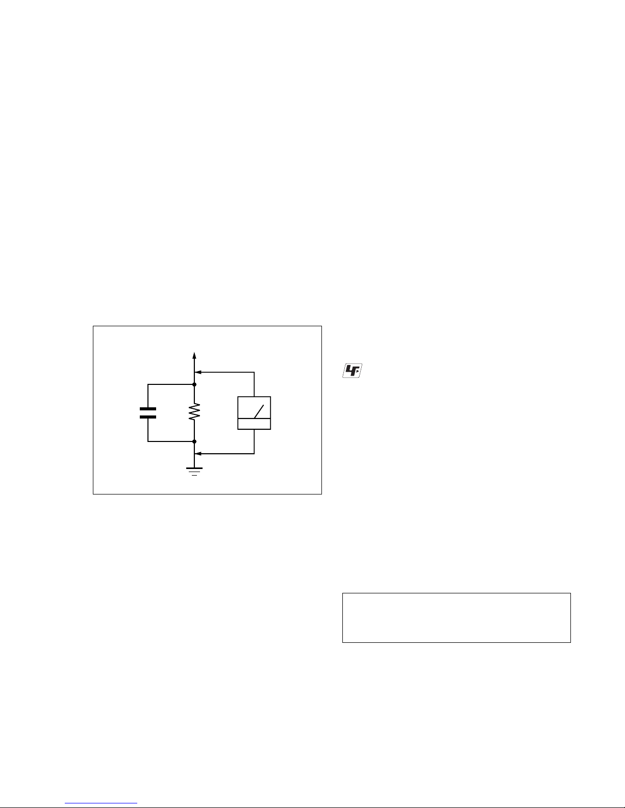
Fig. A. Using an AC voltmeter to check AC leakage.
1.5 k
Ω
0.15 µF
AC
voltmeter
(0.75 V)
To Exposed Metal
Parts on Set
Earth Ground
LEAKAGE TEST
The AC leakage from any exposed metal part to earth ground
and from all exposed metal parts to any exposed metal part having
a return to chassis, must not exceed 0.5 mA (500 microamperes).
Leakage current can be measured by any one of three methods.
1. A commercial leakage tester , such as the Simpson 229 or RCA
WT -540A. F ollow the manufacturers' instructions to use these
instruments.
2. A battery-operated AC milliammeter. The Data Precision 245
digital multimeter is suitable for this job.
3. Measuring the voltage drop across a resistor by means of a V OM
or battery-operated AC voltmeter. The “limit” indication is
0.75V , so analog meters must hav e an accurate low-voltage scale.
The Simpson 250 and Sanwa SH-63Trd are examples of a
passive VOM that is suitable. Nearly all battery operated digital
multimeters that have a 2V A C range are suitable. (See Fig. A)
1. Check the area of your repair for unsoldered or poorly-soldered
connections. Check the entire board surface for solder splashes
and bridges.
2. Check the interboard wiring to ensure that no wires are
“pinched” or contact high-wattage resistors.
3. Look for unauthorized replacement parts, particularly transistors,
that were installed during a previous repair. Point them out to
the customer and recommend their replacement.
4. Look for parts which, though functioning, show obvious signs
of deterioration. Point them out to the customer and recommend
their replacement.
5. Check the line cord for cracks and abrasion. Recommend the
replacement of any such line cord to the customer.
6. Check the B+ voltage to see it is at the values specified.
7. Check the antenna terminals, metal trim, “metallized” knobs,
screws, and all other exposed metal parts for AC leakage. Check
leakage as described below.
SAFETY CHECK-OUT
After correcting the original service problem, perform the following
safety checks before releasing the set to the customer:
Unleaded solder
Boards requiring use of unleaded solder are printed with the leadfree mark (LF) indicating the solder contains no lead.
(Caution: Some printed circuit boards may not come printed with
the lead free mark due to their particular size.)
: LEAD FREE MARK
Unleaded solder has the following characteristics.
• Unleaded solder melts at a temperature about 40°C higher than
ordinary solder.
Ordinary soldering irons can be used but the iron tip has to be
applied to the solder joint for a slightly longer time.
Soldering irons using a temperature regulator should be set to
about 350°C.
Caution: The printed pattern (copper foil) may peel away if the
heated tip is applied for too long, so be careful!
• Strong viscosity
Unleaded solder is more viscous (sticky , less prone to flo w) than
ordinary solder so use caution not to let solder bridges occur such
as on IC pins, etc.
• Usable with ordinary solder
It is best to use only unleaded solder but unleaded solder may
also be added to ordinary solder.

— 4 —
TABLE OF CONTENTS
Precautions
1 Safety Precautions ······························································ 5
2 Servicing Precautions ························································ 7
3 ESD Precautions································································· 8
4 Handling the Optical Pick-up ············································· 9
1. General
Hookups and Settings ······················································1-2
Quick Guide to Disc Types··············································1-6
Playback ·········································································· 1-8
Recording ······································································1-10
Editing ···········································································1-13
DV/D8 Dubbing (DV/D8 t DVD)······························ 1-17
Settings and Adjustments ··············································1-18
Additional Information··················································1-20
2. Disassembly and Reassembly
2-1 Cabinet and PCB ···························································· 2-1
2-1-1 Cabinet Top Removal ·····················································2-1
2-1-2 Ass’y Front Panel Removal············································ 2-1
2-1-3 Chassis Removal ···························································· 2-2
2-2 Circuit Board Locations ·················································2-3
3. Block Diagram..........................................................3-1
4. PCB Diagrams
4-1 DVD Main PCB ······························································4-3
4-2 Front Main PCB ······························································4-7
4-3 Function Timer PCB ······················································4-11
5. Schematic Diagrams
5-1 S.M.P.S (Front Main PCB)··············································5-3
5-2 Power (Front Main PCB)·················································5-5
5-3 Logic (Front Main PCB) ·················································5-7
5-4 ATSC TM & Connector (Front Main PCB) ····················5-9
5-5 MPEG Decoder (DVD Main PCB) ·······························5-11
5-6 A/V Decoder (DVD Main PCB) ···································5-13
5-7 In Out (DVD Main PCB) ··············································5-15
5-8 DV & HDMI (DVD Main PCB) ··································· 5-17
5-9 Front Panel (Function Timer PCB) ·······························5-19
5-10 Function & Jack (VCR Front Main PCB) ·····················5-21
6. Troubleshooting·················································6-1
7. Repair Parts List
7-1 Exploded Views ·······························································7-2
7-2 Electrical Parts List ·························································7-3
— 5 —
PRECAUTIONS
1 SAFETY PRECAUTIONS
1) Before returning an instrument to the customer, always make a
safety check of the entire instrument, including, but not limited
to, the following items:
(1) Be sure that no built-in protective devices are defective or ha ve
been defeated during servicing.
(1)Protective shields are provided to protect both the technician
and the customer. Correctly replace all missing protective
shields, including any removed for servicing convenience.
(2)When reinstalling the chassis and/or other assembly in the
cabinet, be sure to put back in place all protective devices,
including, but not limited to, nonmetallic control knobs,
insulating fish papers, adjustment and compartment covers/
shields, and isolation resistor/capacitor networks. Do not operate
this instrument or permit it to be operated without all protective
devices correctly installed and functioning.
(2) Be sure that there are no cabinet openings through which adults
or children might be able to insert their fingers and contact a
hazardous voltage. Such openings include, but are not limited
to, excessively wide cabinet ventilation slots, and an improperly
fitted and/or incorrectly secured cabinet back cover.
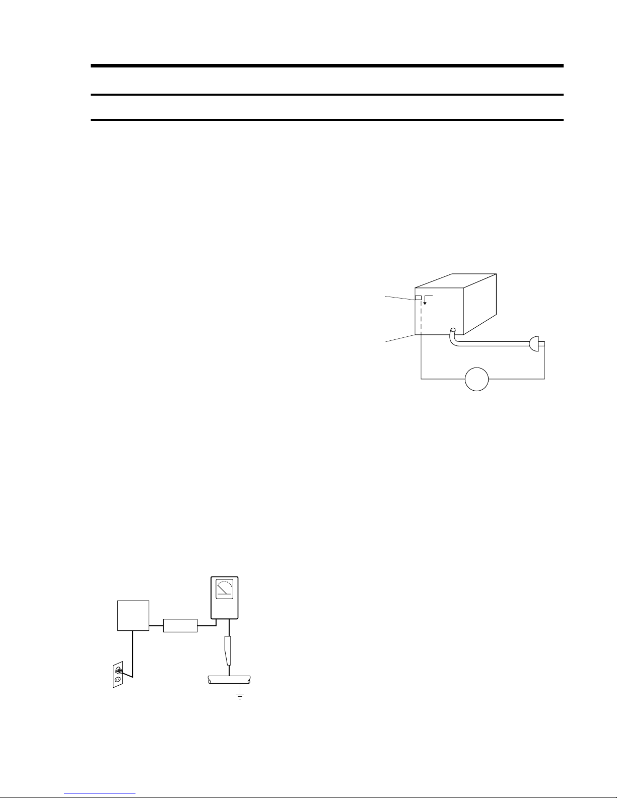
(3) Leakage Current Hot Check-With the instrument completely
reassembled, plug the AC line cor d directly into a 120V AC
outlet. (Do not use an isolation transformer during this test.)
Use a leakage current tester or a metering system that complies
with American National Standards institute (ANSI) C101.1
Leakage Current for Appliances and Underwriters Laboratories
(UL) 1270 (40.7). With the instrument’s AC switch first in the
ON position and then in the OFF position, measure from a known
earth ground (metal water pipe, conduit, etc.) to all exposed
metal parts of the instrument (antennas, handle brackets, metal
cabinets, screwheads, metallic overlays, control shafts, etc.),
especially any exposed metal parts that offer an electrical return
path to the chassis.
Any current measured must not exceed 0.5mA. Reverse the
instrument power cord plug in the outlet and repeat the test. See
Fig. 1.
Any measurements not within the limits specified herein indicate
a potential shock hazard that must be eliminated before returning
the instrument to the customer.
(4) Insulation Resistance Test Cold Check-(1) Unplug the power
supply cord and connect a jumper wire between the two prongs
of the plug. (2) Turn on the po wer switch of the instrument. (3)
Measure the resistance with an ohmmeter between the jumpered
AC plug and all exposed metallic cabinet parts on the instrument,
such as screwheads, antenna, control shafts, handle brackets,
etc. When an exposed metallic part has a return path to the
chassis, the reading should be between 1 and 5.2 megohm. When
there is no return path to the chassis, the reading must be infinite.
If the reading is not within the limits specified, there is the
possibility of a shock hazard, and the instrument must be repared
and rechecked before it is returned to the customer. See Fig. 2.
DEVICE
UNDER
TEST
(READING SHOULD
NOT BE ABOVE
0.5mA)
LEAKAGE
CURRENT
TESTER
EARTH
GROUND
TEST ALL
EXPOSED METER
SURFACES
ALSO TEST WITH
PLUG REVERSED
(USING AC ADAPTER
PLUG AS REQUIRED)
2-WIRE CORD
Fig. 1 AC Leakage Test
Fig. 2 Insulation Resistance Test
2) Read and comply with all caution and safety related notes on or
inside the cabinet, or on the chassis.
3) Design Alteration W arning-Do not alter or add to the mechanical
or electrical design of this instrument. Design alterations and
additions, including but not limited to, circuit modifications and
the addition of items such as auxiliary audio output connections,
might alter the safety characteristics of this instrument and create
a hazard to the user. Any design alterations or additions will
make you, the servicer, responsible for personal injury or
property damage resulting therefrom.
4) Observe original lead dress. Take extra care to assure correct
lead dress in the following areas:
(1) near sharp edges, (2) near thermally hot parts (be sure that
leads and components do not touch thermally hot parts), (3) the
AC supply, (4) high voltage, and (5) antenna wiring. Always
inspect in all areas for pinched, out-of-place, or frayed wiring,
Do not change spacing between a component and the printedcircuit board. Check the AC power cord for damage.
5) Components, parts, and/or wiring that appear to have overheated
or that are otherwise damaged should be replaced with
components, parts and/or wiring that meet original
specifications.
Additionally, determine the cause of o verheating and/or damage
and, if necessary, take correcti ve action to remov e any potential
safety hazard.
Antenna
Terminal
Exposed
Metal Part
ohm
ohmmeter

— 6 —
6) Product Safety Notice-Some electrical and mechanical parts
have special safety-related characteristics which are often not
evident from visual inspection, nor can the protection they giv e
necessarily be obtained by replacing them with components rated
for higher voltage, wattage, etc. Parts that have special safety
characteristics are identified by shading, an ( ) or a ( ) on
schematics and parts lists. Use of a substitute replacement that
does not have the same safety characteristics as the
recommended replacement part might create shock, fire and/or
other hazards. Product safety is under review continuously and
new instructions are issued whenever appropriate.

— 7 —
2 SERVICING PRECAUTIONS
CAUTION: Before servicing units covered by this service manual
and its supplements, read and follow the Safety Precautions section
of this manual.
Note: If unforseen circumstances create conflict between the
following servicing precautions and any of the safety precautions,
always follow the safety precautions. Remember: Safety First.
2-1 General Servicing Precautions
(1) a. Always unplug the instrument’s A C po wer cord from the AC
power source before (1) re-moving or reinstalling any
component, circuit board, module or any other instrument
assembly, (2) disconnecting an y instrument electrical plug or
other electrical connection, (3) connecting a test substitute in
parallel with an electrolytic capacitor in the instrument.
b. Do not defeat any plug/socket B+ voltage interlocks with
which instruments covered by this service manual might be
equipped.
c. Do not apply AC power to this instrument and/or any of its
electrical assemblies unless all solid-state device heat sinks
are correctly installed.
d. Always connect a test instrument’s ground lead to the
instrument chassis ground before connecting the test
instrument positive lead. Always remove the test instrument
ground lead last.
Note: Refer to the Safety Precautions section ground lead last.
(2) The service precautions are indicated or printed on the cabinet,
chassis or components. When servicing, follow the printed or
indicated service precautions and service materials.
(3)The components used in the unit have a specified flame
resistance and dielectric strength.
When replacing components, use components which have the
same ratings. Components identified by shading, by ( ) or by
( ) in the circuit diagram are important for safety or for the
characteristics of the unit. Always replace them with the exact
replacement components.
(4) An insulation tube or tape is sometimes used and some
components are raised above the printed wiring board for safety .
The internal wiring is sometimes clamped to prevent contact
with heating components. Install such elements as they were.
(5) After servicing, always check that the removed screws,
components, and wiring have been installed correctly and that
the portion around the serviced part has not been damaged and
so on. Further, check the insulation between the blades of the
attachment plug and accessible conductive parts.
2-2 Insulation Checking Procedure
Disconnect the attachment plug from the AC outlet and turn the
power ON. Connect the insulation resistance meter (500V) to the
blades of the attachment plug. The insulation resistance between
each blade of the attachment plug and accessible conductive parts
(see note) should be more than 1 Megohm.
Note: Accessible conductive parts include metal panels, input
terminals, earphone jacks, etc.

— 8 —
3 ESD PRECAUTIONS
Electrostatically Sensitive Devices (ESD)
Some semiconductor (solid state) devices can be damaged easily
by static electricity.
Such components commonly are called Electrostatically Sensitive
Devices (ESD). Examples of typical ESD devices are integrated
circuits and some field-effect transistors and semiconductor chip
components. The following techniques should be used to help reduce
the incidence of component damage caused by static electricity.
(1) Immediately before handling any semiconductor component or
semiconductor-equipped assembly, drain off any electrostatic
charge on your body by touching a known earth ground.
Alternatively, obtain and wear a commercially available
discharging wrist strap device, which should be removed for
potential shock reasons prior to applying power to the unit under
test.
(2) After removing an electrical assembly equipped with ESD
devices, place the assembly on a conductive surface such as
aluminum foil, to prevent electrostatic charge buildup or
exposure of the assembly.
(3) Use only a grounded-tip soldering iron to solder or unsolder
ESD devices.
(4) Use only an anti-static solder removal devices. Some solder
removal devices not classified as “anti-static” can generate
electrical charges sufficient to damage ESD devices.
(5) Do not use freon-propelled chemicals. These can generate
electrical charges sufficient to damage ESD devices.
(6) Do not remove a replacement ESD device from its protective
package until immediately before your are ready to install it.
(Most replacement ESD devices are packaged with leads
electrically shorted together by conductive foam, aluminum foil
or comparable conductive materials).
(7) Immediately before removing the protective materials from the
leads of a replacement ESD device, touch the protective material
to the chassis or circuit assembly into which the device will be
installed.
CAUTION: Be sure no power is applied to the chassis or circuit,
and observe all other safety precautions.
(8) Minimize bodily motions when handling unpackaged
replacement ESD devices. (Otherwise harmless motion such as
the brushing together of your clothes fabric or the lifting of
your foot from a carpeted floor can generate static electricity
sufficient to damage an ESD device).
— 9 —
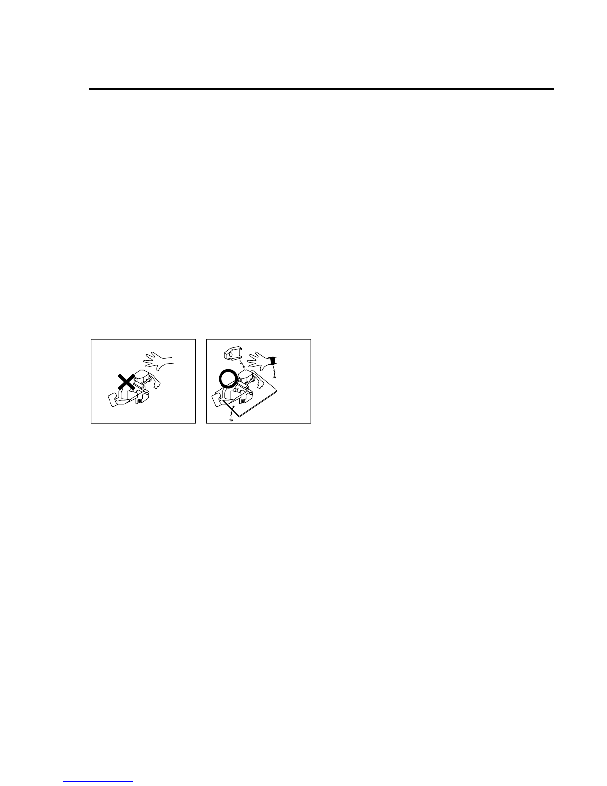
4 HANDLING THE OPTICAL PICK-UP
The laser diode in the optical pick up may suffer electrostatic
breakdown because of potential static electricity from clothing and
your body.
The following method is recommended.
(1) Place a conductive sheet on the work bench (The black sheet
used for wrapping repair parts.)
(2) Place the set on the conductive sheet so that the chassis is
grounded to the sheet.
(3) Place your hands on the conductive sheet (This gives them the
same ground as the sheet.)
(4) Remove the optical pick up block
(5) Perform work on top of the conductive sheet. Be careful not to
let your clothes or any other static sources to touch the unit.
◆ Be sure to put on a wrist strap grounded to the sheet.
◆ Be sur e to lay a conducti ve sheet made of copper etc. Which is
grounded to the table.
Fig.3
(6) Short the short terminal on the PCB, which is inside the Pick-
Up ASS’Y, before replacing the Pick-Up. (The short terminal is
shorted when the Pick-Up Ass’y is being lifted or moved.)
(7) After replacing the Pick-up, open the short terminal on the PCB.
THE UNIT
WRIST-STRAP
FOR GROUNDING
1M
1M
CONDUCTIVE SHEET

— 10 —
5 Reset operation after IC104 was replaced
Be sure to perform the reset by the method described below, if the
IC104 (FLASH MEMORY) used on the DVD Main board was
replaced.
Resetting method
1. Enter the Adjustment mode, and press tw o times the “1” button
on the remote commander.
(For an entering method of Adjustment mode, see 6-1.)
The tray will automatically open and the version information
will be displayed on the TV screen.
2. Turn the power off.
1-1
1. GENERAL
This section is extracted from instruction manual.
(3-096-488-11)
RDR-GXD455
4
About this manual
•Instructions in this manual describe the con trols on the
remote. You can also use the controls on the recorder if
they have the same or si milar names as those on the
remote.
•The on-screen display illustrations used in this manual
may not match the graphics displayed on your TV
screen.
•The explanations regarding discs in this manual refer to
discs created on this recorder. The explanations do not
apply to discs that are created on other recorders and
played back on this recorder.
*MP3 (MPEG1 Audio Layer 3) is a standard format
defined by ISO/MPEG which compresses audio data.
Icon Meaning
Functions available for DVD+RWs
Functions available for DVD-RWs
in VR (Video Re cording) mode
Functions available for DVD-RWs
in video mode
Functions available for DVD+Rs
Functions available for DVD-Rs in
VR (Video Recording) mode
Functions available for DVD-Rs in
video mode
Functions available for DVD
VIDEOs
Functions available for DVD-RAMs
Functions available for VIDEO CDs
or CD-Rs/CD-RWs in video CD
format
Functions available for music CDs
or CD-Rs/CD-RWs in music CD
format
Functions available for DATA CDs
(CD-ROMs/CD-Rs/CD-RWs
containing MP3
* audio tracks or
JPEG image files)
Functions available for DATA
DVDs (DVD-ROMs/DVD+RWs/
DVD-RWs/DVD+Rs/DVD-Rs
containing MP3* audio tracks or
JPEG image files)
+
RW
-
RWVR
-
RWVideo
+
R
-
RVR
-
RVideo
DVD
RAM
VCD
CD
DATA CD
DATA DVD
8
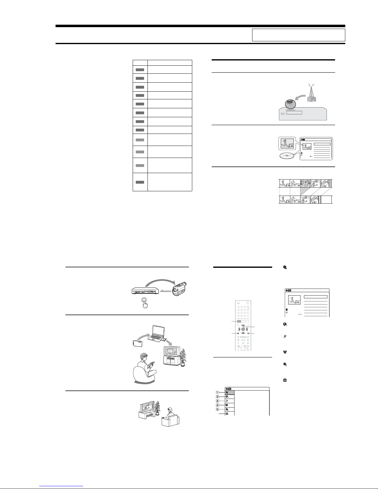
Ways to Use Your DVD Recorder
Recording and timer recording
, Record TV programs on a DVD, either
manually or using the timer.
Quick access to recorded titles – Title List
, Display the Title List to view all titles on a
disc and select a title for playback or editing
(page 40).
Creating your own program – Playlist
, Record a program on a DVD-RW (VR
mode) or DVD-R (VR mode), then erase,
move or add scenes as you like without
changing the original cont ents (page 62).
Title List
10:10 AM
>
>
>
>
D11.1
08:00 PM
May/02/2007
T
No.1/4
01
02
03
04
Title Length Edit
D11.1 01:29:03
D22.2 00:31:23
Ch 23 01:59:00
Ch 66 00:58:56
Title List (Original)
Original
Playlist
9
One Touch Dubbing – DV/D8 Dubbing
, Connect your digital video camera to the
DV IN jack and press the ONE TOUCH
DUBBING button to dub a DV/D8 format
tape over to a disc (page 71).
Playing JPEG image files or MP3 audio files
, You can enjoy viewing JPEG images on
your TV screen. First, take pictures with a
digital camera and save them in JPEG
format to a DATA CD (CD-RW/CD-R) or
DATA DVD (DVD+RW/DVD-RW/
DVD+R/DVD-R) on a PC. Then play the
disc on this recorder (page 43).
You can also play MP3 audio files on thi s
recorder (page 42).
A list of recordable and playable discs is on page 12.
Progressive playback
, If your TV is compatible with progressive
signals, you can enjoy accurate color
reproduction and high quality images in
Progressive mode (page 80).
+
-
ONE-TOUCH DUBBING
Control
Dubbing
Shoot
Save
Play!
10
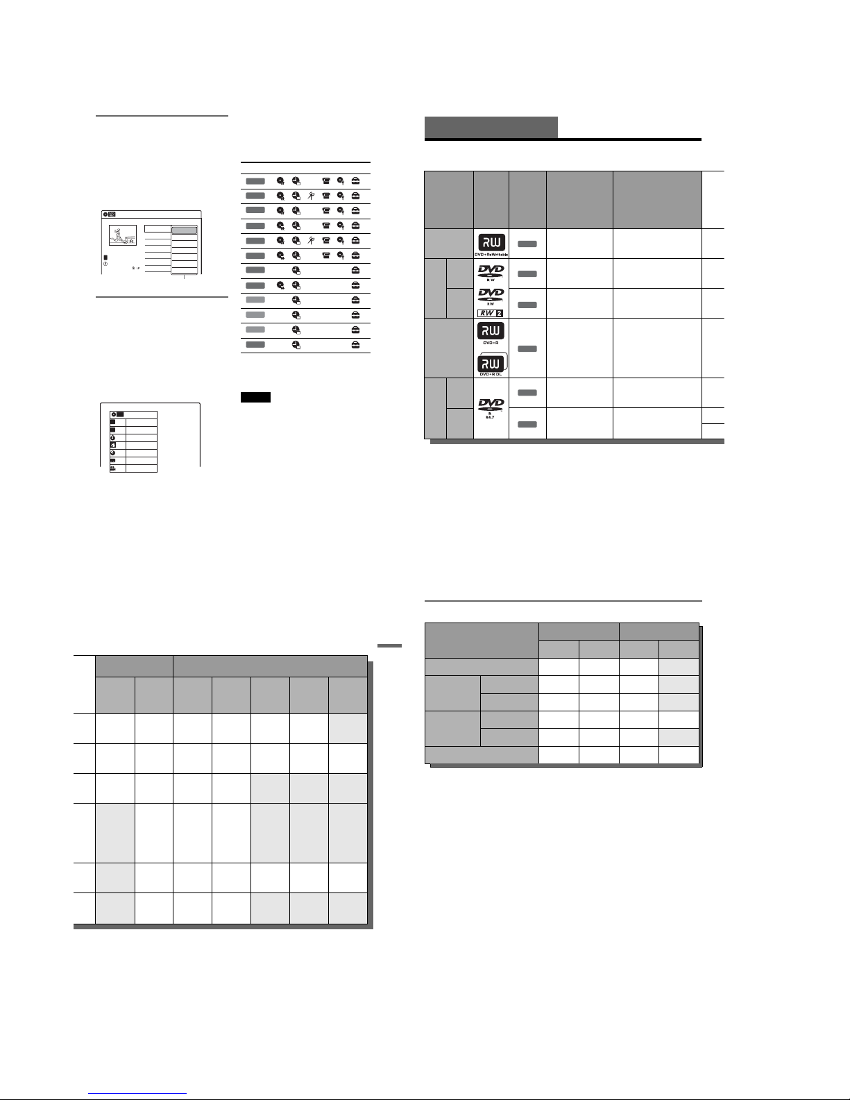
How to Use the On-Screen
Menus
The following three displays are mainly used to
operate this recorder. Once you become familiar
with the basic operations, you w ill find the
recorder easy to use.
System Menu
The System Menu appears when y ou press
SYSTEM MENU, and provides entr ies to all of
the recorder’s main functions, such as timer
recording and setup.
Select an option by pressing M/m an d ENTER.
A “Title List”
Displays the list of the disc contents,
including the recording information and
movie thumbnail image, which allows you to
select a title to play or edit.
B “Timer”
Used to set a new timer recording, as well as
change or cancel the timer recordings you set.
C “Edit”
Used to create or edit a Playlist (unfinalized
DVD-RWs (VR mode)/DVD-Rs (VR mode)
only).
D “DV/D8 Dubbing”
Used to dub from a DV/D8 format tape to a
disc.
E “Disc Setting”
Used to rename, protect, format, or finalize a
disc, and erase all titles on the disc. Also,
displays the disc information.
F “Setup”
Displays the “Setup” displ ay for setting up the
recorder to suit your preferences.
M/m/</,,
ENTER
SYSTEM
MENU
OPTIONSO RETURN
11 22 33
44 55 66
77 880099
Title List (Original)
10:10 AM
Press ENTER :
Title Menu for DVD Title List.
Setup
Disc Setting
Edit
Title List
Timer
DV/D8 Dubbing
6
10:10 AM
01 >01:29:03
02 >00:31:23
03 >01:59:00
04 >00:58:56
08:00 PM
T
No. Title Length Edit
Title List (Original)
1/4
D11.1
D22.2
Ch 23
Ch 66
D11.1
May/02/2007
1-2
11
Sub-menu
The sub-menu appears when yo u select an item
from a list menu (e.g., a title from the Title List
menu), and press ENTER. The sub-menu d isplays
options applicable only to the selected item. T he
displayed options differ depending on the
situation and disc type.
Select an option by pressing M/m and ENTER.
Example: The Title List menu
OPTIONS
The OPTIONS menu appears w hen you press
OPTIONS. You can search for a title/chapter/
track, check the playing and remaining time, or
change settings for au dio/angle/subtitle. The
displayed options differ depending on the media
type.
Press M/m to select an opti on, press </, to
select the desired item, and press ENTER.
Example: When you press OPTIONS while a
DVD VIDEO is playing.
Selectable options
Selectable options on the System Menu differ
depending on the media type, disc condition, and
operating status.
Example: When a disc is stopped.
*Unfinalized disc only
To return to the previous display
Press O RETURN.
Notes
•The OPTIONS menu may not appear during DVD
recording.
•The System Menu does not appear when recording on
a DVD.
Title List (Original)
10:10 AM
No. Title Length Edit
01 D11.1 >01:29:03
02 D22.2 >00:31:23
03 Ch 23 >01:59:00
04 Ch 66 >00:58:56
D11.1
May/02/2007
08:00 PM
T
1/4
Play
Title Erase
Chapter Erase
Protect
Title Name
A·B Erase
Divide Title
Options for the selected item
1/4
1/1
00:00:25
T
C
Title
Chapter
Time
Remain
Audio
Angle
00:01:30
Subtitle
2/2 ENG
1/1
ENG Dolby D2ch (1/1)
DVD
VIDEO
Type Selectable option
+
RW
-
RW
VR
**
-
RW
Video
**
+
R
***
-
R
VR
***
-
R
Video
***
DVD
RAM
VCD
CD
DATA CD
DATA DVD
12
Quick Guide to Disc Typ es
Recordable and Playable Discs
Usable disc versions (as of March 2007)
•8×-speed or slower DVD+RW s
•6×-speed or slower DVD-RWs (Ver.1.1, Ver.1.2
with CPRM
*1
)
•16×-speed or slower DVD+Rs
•16×-speed or slower DVD-Rs (Ver.2.0, Ver.2.1
with CPRM)
•8×-speed or slower DVD +R DL (Double Layer)
discs
*6
“DVD+RW,” “DVD-RW,” “DVD+R,” “DVD+R DL,”
and “DVD-R” logos are trademarks.
Disc Type
Disc
Logo
Icon used
in this
manual
Formatting
(new discs)
Compatibility with other
DVD players (finalizing)
DVD+RW
Automatically
formatted
Playable on DVD+RW
compatible players
(automatically finalized)
DVDRW
VR
mode
Format in VR mode*2
(page 48)
Playable only on VR mode
compatible players (finalization
unnecessary) (page 69)
Video
mode
Format in Video
mode
*2
(page 48)
Playable on most DVD players
(finalization necessary)
(page 69)
DVD+R
Automatically
formatted
Playable on DVD+R compatible
players (finalization necessary)
(page 69)
DVD+R DL
DVDR
VR
mode
Format in VR mode
using the “Disc Setting”
display (page 68)
Playable only on DVD-R VR
mode compatible players
(finalization necessary)
(page 69)
Video
mode
Automatically
formatted in Video
mode
Playable on most DVD players
(finalization necessary)
(page 69)
+
RW
-
RW
VR
-
RW
Video
+
R
-
R
VR
-
R
Video
13
Quick Guide to Disc Types
*1
CPRM (Content Protection for Recor dable Media) is
a coding technology that protects copyrights for
images.
*2
Unused DVD-RWs are automatically formatted
according to the setting of “Format DVD-RW” in
“Features” setup (page 84).
*3
Erasing titles only frees up disc space if you erase the
last title.
*4
Erasing titles or chapters frees up disc space.
*5
Erasing titles or chapters does not free up disc space.
*6
When using DVD+R DL (Double Layer) discs, see
the instructions supplied with the discs.
Recording Features Editing Features
Rewrite
(page 68)
Auto
Chapter
(page 50)
Change
Title Name
(page 61)
Erase
Title/
Chapter
(page 58)
A-B Erase
(page 59)
Divide
Title
(page 60)
Playlist
(page 62)
Yes Yes Yes Yes/No
*3
Yes Yes No
Yes Yes YesYes/Yes
*4
Yes Yes Yes
Yes Yes Yes Yes/No
*3
No No No
No Yes Yes Yes/No
*5
No No No
No Yes Yes Yes/Yes
*5
Yes Yes Yes
No Yes Yes Yes/No
*5
No No No
,continued
14
12 cm/8 cm discs
Discs that cannot be recorded on
•8 cm discs
• DVD-RAMs
Disc Type
12 cm 8 cm
Playback Recording Playback Recording
DVD+RW Yes Yes Yes No
DVD-RW
VR mode Yes Yes Yes No
Video mode Yes Yes Yes No
DVD-R
VR mode Yes Yes — —
Video mode Yes Yes Yes No
DVD+R Yes Yes — —
1-3
15
Quick Guide to Disc Types
Playable Discs
“DVD VIDEO” and “CD” logos are trademarks.
*A logical format of files and folders on DATA-CDs,
defined by ISO (International Organiz ation for
Standardization).
Discs that cannot be played
•CD-ROMs/CD-Rs/CD-RWs that are not
recorded in music CD or Video CD format, or do
not contain MP3 audio tracks or JPEG image
files.
•Data part of CD-Extras
• DVD-ROMs that are not recorded in DVD
Video format, or do not contain MP3 audio
tracks or JPEG image files.
• DVD Audio discs
• HD layer on Super A udio CDs
• DVD VIDEOs with a different region code
(see page 16)
•A disc recorded in a color system other than
NTSC, such as PAL or SECAM
Disc Type Disc Logo
Icon Used
in This
Manual
Characteristics
DVD VIDEO
Discs such as movies that can be purchased or
rented
DVD-RAM —
DVD-RAMs recorded by another recording
device. 12 cm discs without cartridges, or
removable from their cartridges c an be played.
VIDEO CD
VIDEO CDs or CD-Rs/CD-RWs in VIDEO CD
format (with PBC function)
CD
Music CDs or CD-Rs/CD-RWs in music CD
format that can be purchased
DATA CD
CD-ROMs/CD-Rs/CD-RWs created on a PC or
similar device in music format, or MP3 or JPEG
format that conforms to ISO9660* Lev el 1/
Level 2
DATA DVD —
DVD-ROMs/DVD+RWs/DVD-RWs/DVD+Rs/
DVD-Rs in MP3 or JPEG format conforming to
Universal Disk Format (UDF)
8 cm DVD+RW/
DVD-RW/DVD-R
——
8 cm DVD+RWs, DVD-RWs, and DVD-Rs
recorded with a DVD video camera (Still images
recorded with a DVD video camera cannot be
played.)
DVD
RAM
VCD
CD
DATA CD
DATA DVD
,continued
16
Note on playback operations of DVD VIDEOs/
VIDEO CDs
Some playback operations of DVD VIDEOs/
VIDEO CDs may be intentionally set by softw are
producers. Since this record er plays DVD
VIDEOs/VIDEO CDs according to the disc
contents the software producers designed, some
playback features may not be available. Also, see
the instructions supplied with the DVD VIDEOs/
VIDEO CDs.
Note on DualDiscs
A DualDisc is a two sided disc product which
mates DVD recorded material on one side with
digital audio material on the other side.
However, since the audio material side d oes not
conform to the Compact Disc (CD ) standard,
playback on this product is not guaran teed.
Region code (DVD VIDEO only)
Your recorder has a region code prin ted on the rear
of the unit and will only play DVD VIDEOs
(playback only) labeled with identical region
codes. This system is used to prote ct copyrights.
DVD VIDEOs labeled will also play on this
recorder.
If you try to play any other DVD VI DEO, a
message will appear on the TV screen to indicate
that the disc is not playable. Depending on the
DVD VIDEO, no region code indication may be
labeled even though playing the DVD VIDEO is
prohibited by area restrictio ns.
Music discs encoded with copyright protection
technologies
This product is designed to playback discs that
conform to the Compact Disc (CD ) standard.
Recently, various music discs encoded with
copyright protection technolo gies are being
marketed by some record companie s. Please be
aware that among those disc s, there are some that
do not conform to the CD standard and may not be
playable by this product.
Note on DVD+RWs/DVD+Rs, DVD-RWs/DVDRs, or CD-RWs/CD-Rs recorded on other
equipment
Some DVD+RWs/DVD+Rs, DVD-RWs/DVDRs, or CD-RWs/CD-Rs cannot be played on this
recorder due to the recording quality or physical
condition of the disc, or the characteristics of the
recording device and authoring software. The disc
will not play if it has not been correctly finalized.
For more information, see the operating
instructions for the recording de vice.
Notes
•You c annot mix VR mode and Video mode on the same
DVD-RW or DVD-R. To change the DVD-RW’s
format, reformat the disc (page68). Note that a disc’s
contents will be erased after reformatting.
•You ca nnot shorten the time required for recording
even with high-speed discs. Also, you cannot record on
the disc if the disc is not 1x speed comp atible.
•It is recommended that you use discs with “For Video”
printed on their packaging.
•You canno t add new recordings to DVD-RWs (Video
mode), DVD+R, or DVD-Rs (Video mode) recorded
on other equipment.
•You may not be a ble to further record on a DVD+RW
recorded on other equipment. Note that recording on
such discs may cause the recorder to rewrite the DVD
menu.
• If the disc contain s PC data unrecognizable by this
recorder, the data may be erased.
ALL
X
Region code
17
Hookups and Settings
Hookups and Settings
Hooking Up the Recorder
Follow steps 1 to 7 to hook up and adju st the
settings of the recorder.
Notes
•Plug cords securely to prevent unwanted noise.
•See the instr uctions supplied with the components to be
connected.
•You cannot connect this recorder to a TV that does not
have a video input jack.
•Be sure to disconnect the power cord of each
component before connecting. Do not connec t the
power cord until you reach “Connecting the Power
Cord” on page 26.
Step 1: Unpacking
Check that you have the following items:
•Audio/video cord
(phono plug u 3 y phono plug u 3) (1)
•Antenna cable (1)
•Remote commander (remote) (1)
•Size AA (R6) batteries (2)
Step 2: Connecting the
Antenna Cable
Select one of the following antenn a hookups. Do
not connect the power cord until you reach
“Connecting the Power Cord” on page 2 6.
Notes
•If your a ntenna is a flat cable (300-ohm twin lead
cable), use an external antenna connector (not
supplied) to connect the antenna to the recorder.
•If you have separate cables for VHF and UHF
antennas, use a UHF/VHF band mixer (not supplied) to
connect the ant enna to the recorder.
If you have Hookup
Cable box or satellite receiver with a
video/audio output
A (page 18)
Cable box with an antenna output
only
B (page 19)
Cable without cable box, or an tenna
only (no cable TV)
C (page 20)
,continued
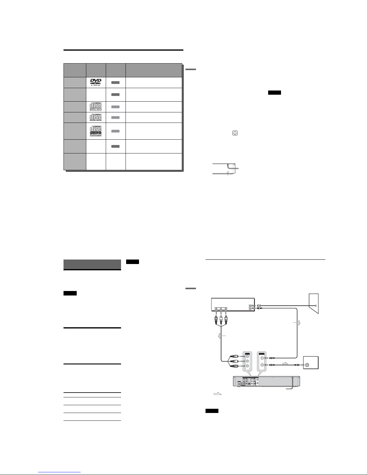
18
A: Cable box or satellite receiver with a video/audio output
With this hookup, you can record any channel on the cable box or satellite receiver. Be sure that the cable
box or satellite receiver is turned on. This connection is necessary to use the Synchro-Rec function
(page 53).
To watch cable or satellite programs, you need to match the channel on the recorder (LINE1) to the input
jack connected to the cable box or satellite receiver (LINE 1 IN).
Note
Synchro-Recording does not work with some tuners. For deta ils, see the tuner’s operating instructions.
L
R
VIDEO
AUDIO
LINE OUT VHF/UHF
VIDEO
YL
P
B
R
P
R
AUDIO
LINE 1 IN
AUDIO OUT S VIDEO OUT
COMPONENT
VIDEO OUT
DIGITAL AUDIO OUT
OPTICAL COAXIAL
HDMI OUT
IN
OUT
ANT IN
RL
AUDIO
OUT
VIDEO
OUT
TO TV
VIDEO
LINE 1 IN
AUDIO
VHF/UHF
IN
OUT
Cable box/
satellite receiver
Antenna cable
(supplied)
to antenna input
Audio/video
cord (not supplied)
to LINE 1 IN
DVD recorder
: Signal flow
to VHF/UHF IN
to VHF/UHF
OUT
TV
Wall
1-4
19
Hookups and Settings
B: Cable box with an antenna output only
With this hookup, you can record any channel on the satellite receiver or cable box. Be sure that the cable
box or satellite receiver is turned on.
To record cable programs, yo u need to match the channel on the recorder (2ch , 3ch or 4ch) to the antenna
output channel on the cable box (2 ch, 3ch or 4ch).
L
R
VIDEO
AUDIO
LINE OUT VHF/UHF
VIDEO
YL
P
B
R
P
R
AUDIO
LINE 1 IN
AUDIO OUT S VIDEO OUT
COMPONENT
VIDEO OUT
DIGITAL AUDIO OUT
OPTICAL COAXIAL
HDMI OUT
IN
OUT
VHF/UHF
IN
OUT
ANT IN
TO TV
Antenna cable
(supplied)
Cable box
DVD recorder
to VHF/UHF IN
to VHF/UHF
OUT
to antenna input
: Signal flow
TV
Wall
,continued
20
C: Cable without cable box, or antenna only (no cable TV)
Use this hookup if you watch cable channel s without a cable box. Also use this hookup if you are using
a VHF/UHF antenna or separate V HF and UHF antennas.
With this hookup, you can record any channel by selecting th e channel on the recorder.
L
R
VIDEO
AUDIO
LINE OUT VHF/UHF
VIDEO
YL
P
BR
P
R
AUDIO
LINE 1 IN
AUDIO OUT S VIDEO OUT
COMPONENT
VIDEO OUT
DIGITAL AUDIO OUT
OPTICAL COAXIAL
HDMI OUT
IN
OUT
VHF/UHF
IN
OUT
to VHF/UHF
OUT
to antenna input
: Signal flow
DVD recorder
to VHF/UHF IN
Antenna cable
(supplied)
TV
Wall
21
Hookups and Settings
Step 3: Connecting to Your TV
Connect the supplied audio/vide o cord to the LINE OUT (VIDEO/AUDIO L/R) jacks of the r ecorder.
To enjoy higher quality images, con nect an S video cord (not supplied) instead of th e yellow (video) plug.
When using this connection, be sure to connect the audio cord to the LINE OUT (AUDIO L/R) jacks.
When playing “wide screen” imag es
Some recorded images may not fit your TV screen. To change the picture size, see page 79.
Notes
•Do not connect to the S VIDEO OUT and yellow LINE OUT (VIDEO) jacks at the same time.
•Do not connect your TV’s audio output jacks to the LINE IN (AUDIO L/R) jacks at the same time. This will cause
unwanted noise to come from your TV’s speakers.
L
R
VIDEO
AUDIO
LINE OUT VHF/UHF
VIDEO
YL
P
B
R
P
R
AUDIO
LINE 1 IN
AUDIO OUT S VIDEO OUT
COMPONENT
VIDEO OUT
DIGITAL AUDIO OUT
OPTICAL COAXIAL
HDMI OUT
IN
OUT
L
R
VIDEO
AUDIO
LINE OUT
VIDEO
AUDIO
LINE 1 IN
S VIDEO OUT
AUDIO
INPUT
RLVIDEO
INPUT
S VIDEO
: Signal flow
S video cord
(not supplied)
TV or projector
(red) (white) (yellow)
Audio/video cord
(supplied)
(red)
(white)
(yellow)
to S VIDEO OUT
DVD recorder
to LINE OUT
(VIDEO/AUDIO L/R)
,continued
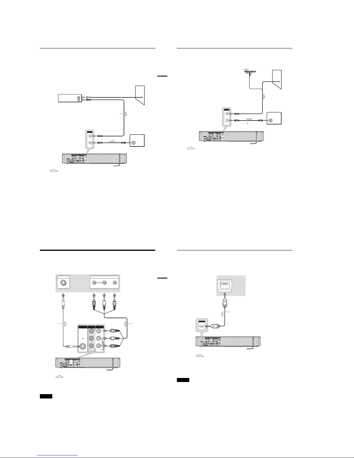
22
If your TV has an HDMI input jack
Connect the HDMI* OUT jack using a certified HDMI cord (not supplied). You will enjoy high-quality
picture and sound. The HDMI indic ator lights up on the front panel when the recorder outputs signals
through the HDMI OUT jack.
Be sure to turn off the recorder before conne cting an HDMI cord.
*This DVD recorder incorporates High-Definition Multimedia Interface (HDMITM) technology.
HDMI, the HDMI logo and High-Definition Multimedia Interface are trademarks or registered trademarks of HDMI
Licensing LLC.
Notes
•You cannot connect the HDMI OUT jack to DVI jacks that are not HDCP compliant (e.g., DVI jacks on PC displays).
• HD ( High Definition) signal through this recorder is converted to SD (Standard Definition) signal, even if the HDMI
OUT connection is used.
L
R
VIDEO
AUDIO
LINE OUT VHF/UHF
VIDEO
YL
P
B
R
P
R
AUDIO
LINE 1 IN
AUDIO OUT S VIDEO OUT
COMPONENT
VIDEO OUT
DIGITAL AUDIO OUT
OPTICAL COAXIAL
HDMI OUT
IN
OUT
HDMI IN
HDMI OUT
: Signal flow
TV or
projector
to HDMI OUT
DVD recorder
HDMI cord (not supplied)
to HDMI input
1-5
23
Hookups and Settings
If your TV has component video input jacks
Connect the COMPONENT VIDE O OUT jacks using a component video cord (not supplied) or three
video cords (not supplied) of the same kind and length. You will enjoy accurate color reproduction and
high quality images.
If your TV accepts progressive 480p for mat signals, you must use this connection and then set
“Progressive” of “Video” to “On” in the “Setup” display (page 80). The “PROGRESSIVE” indicator
lights up when the recorder outputs progressive signals.
When using this connection, be sure to connect the audio cord to the LINE OUT (AUDIO L/R) jacks.
L
R
VIDEO
AUDIO
LINE OUT VHF/UHF
VIDEO
YL
P
B
R
P
R
AUDIO
LINE 1 IN
AUDIO OUT S VIDEO OUT
COMPONENT
VIDEO OUT
DIGITAL AUDIO OUT
OPTICAL COAXIAL
HDMI OUT
IN
OUT
L
R
VIDEO
AUDIO
LINE OUT
Y
P
B
P
R
COMPONENT
VIDEO OUT
COMPONENT VIDEO IN
PBP
R
Y
AUDIO
LR
INPUT
: Signal flow
TV or projector
(red)
(white) (green)
Component video cord
(not supplied)
(red)(blue)
(red)
(green)
(blue)
to COMPONENT
VIDEO OUT
Audio/video cord
(supplied)
(white)
(red)
to LINE OUT
(AUDIO L/R)
DVD recorder
24
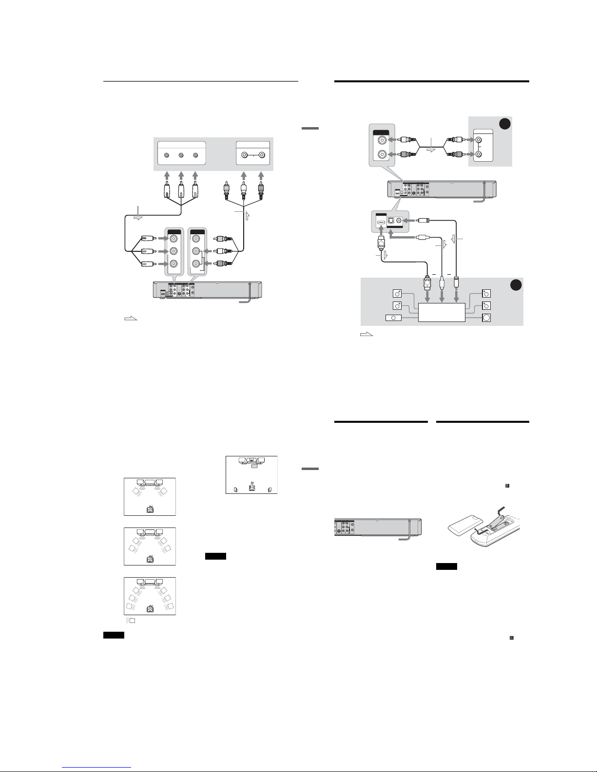
Step 4: Connecting to Your AV Amplifier (Receiver)
Select one of the following patte rns A or B, according to the input jack on your AV amplifier (receiver).
This will enable you to listen to DVD audio tracks through your AV amplifier (receiver).
L
R
VIDEO
AUDIO
LINE OUT VHF/UHF
VIDEO
YL
P
B
R
P
R
AUDIO
LINE 1 IN
AUDIO OUT S VIDEO OUT
COMPONENT
VIDEO OUT
DIGITAL AUDIO OUT
OPTICAL COAXIAL
HDMI OUT
IN
OUT
L
R
AUDIO OUT
AUDIO
INPUT
L
R
B
A
DIGITAL AUDIO OUT
OPTICAL COAXIAL
HDMI OUT
: Signal flow
AV amplifier (receiver)
(red)
(white)
Audio cord
(not supplied) (white)
(red)
DVD recorderto AUDIO OUT (L/R)
to DIGITAL AUDIO OUT
(COAXIAL or OPTICAL)
Optical digital cord
(not supplied)
Coaxial digital cord
(not supplied)
[Speakers]
Rear (L)
Front (L)
Center
[Speakers]
Rear (R)
Front (R)
Subwoofer
or
AV amplifier (receiver)
with a decoder
HDMI cord
(not supplied)
or
to HDMI OUT
to coaxial or optical
digital input
to HDMI input
25
Hookups and Settings
A Connecting to audio L/R jacks
This connection uses a stereo amplifier’s
(receiver’s) two front speakers for sound.
You can enjoy the surround function that creates
virtual speakers from two st ereo speakers. Select
“Surround1,” “Surround2 ,” or “Surround3” in
“Surround” of “Audio” setup (p age 82).
Surround 1
Surround 2
Surround 3
Note
Make sure that your listening position is between and at
an equal distance from your speakers, and that the
speakers are located in similar surroundings.
B Connecting to a digital audio input jack
Use this connection if your AV amplifier
(receiver) has a Dolby
*1
Digital or DTS*2 decoder
and a digital input jack. You can enjoy the
surround effect of Dolby Digital (5.1ch ) or DTS
(5.1ch).
*1
Manufactured under license from Dolby Laboratories.
“Dolby” and the double-D symbol are trademarks of
Dolby Laboratories.
*2
“DTS” and “DTS Digital Out” are trademarks of DTS,
Inc.
z Hint
For correct speaker location, see the operating
instructions supplied with the connected components.
Notes
•After you have completed the connection, make the
appropriate settings under “Audio Connection Setu p”
in Easy Setup (page 29). Otherwise, no sound or a loud
noise will come from your speakers.
•With a coaxial or optical digital connection, you cannot
use the virtual surround effects of this recorder.
•When outputting from the DIGITAL AUDIO OUT
jacks, you cannot switch the bilingual sounds on a
DVD-RW (VR mode) or DVD-R (VR mode) by
pressing AUDIO.
•When you connect the recorder to an AV amplifier
(receiver) using an HDMI cord, you will need to do one
of the following:
–Connect the AV amplifier (receiver) to the TV with
an HDMI cord.
–Connect the recorder to the TV with a video cord
other than HDMI cord (component video cord, S
VIDEO cord, or audio/video cord).
•The HDMI OUT jack cannot output Dolby Digital
signals for digital broadcasts. To hear Dolby Digital,
use the DIGITAL AUDIO OUT jacks.
Virtual speaker
26
Step 5: Connecting the
Power Cord
Plug the recorder and TV powe r cords into an AC
outlet. After you connect the pow er cord, you
must wait for a short while before
operating the recorder. You can opera te the
recorder only after the front panel display lights up
and the recorder enters standb y mode.
If you connect additional equipm ent to this
recorder (page 32) , be sure to connect the po wer
cord only after all connections are complete.
Step 6: Preparing the
Remote
You can control the recorder using the supplied
remote.
Insert two size AA (R6) batteries by matching the
3 and # ends on the batteries to the markings
inside the battery compartment. Be sure to close
the battery cover properly. When using the
remote, point it at the remote sensor on the
recorder.
Notes
•If the supplied remote interferes your other Sony DVD
recorder or player, change the command mode number
for this recorder (page 28).
•Use the batteries correctly to avoid po ssible leakage
and corrosion. Do not touch the liquid with bare hands
should leakage occur. Observe the following:
–Do not use a new battery with an old bat tery, or
batteries of different manufacturers.
–Do not a ttempt to recharge the batteries.
–If you do not intend to us e the remote for an extended
period of time, remove the batteries.
–If battery leakage occurs, wipe out any liquid inside
the battery compartment, and insert new batteries.
•Do no t expose the remote sensor (marked on the
front panel) to strong light, such as direct sunlight or
lighting apparatus. The recorder may not respond to the
remote.
•With normal use, the batteries should last about three to
six months.
•Do not leave the remote in an extremely hot or humid
place.
•Do not d rop any foreign object into the remote casing,
particularly when replacing the batteries.
HDMI OUT
L
R
VIDEO
AUDIO
LINE OUT VHF/UHF
VIDEO
Y
P
B
P
R
AUDIO
LINE 1 IN
S VIDEO OUT
O
NENT
O
OUT
IN
OUT
to AC outlet <
1-6
27
Hookups and Settings
Controlling TVs with the remote
You can adjust the remote control ’s signal to
control your TV.
Notes
•Depending on the TV, some or all of the butto ns below
may not work for the TV.
• If y ou enter a new code number, the code number
previously entered will be erased.
•When you replace the batteries of the remote, the code
number may be reset to the default setting. Set the
appropriate code number again.
1
Hold down TV "/1 located at the bottom of
the remote.
Do not press "/1 at the top of the remote.
2
With TV "/1 pressed down, enter your
TV’s manufacturer code (see below) using
the number buttons.
3
Release TV "/1.
The following buttons are for TV.
Code numbers of controllable TVs
If more than one code number is listed, try
entering them one at a time until you find the one
that works with your TV.
Press To
TV "/1 Turn your TV on or off
TV VOL +/– Adjust the volume of
your TV
TV CH +/– Select the channel on
your TV
11 22 33
44 55 66
77 880099
Number
buttons
TV INPUT
TV VOL +/–
TV DIGITAL/
ANALOG
TV CH +/–
TV "/1
TV INPUT Switch your TV’s input
source
TV DIGITAL /
ANALOG
Select the broadcast on a
Sony TV that can sw itch
between digital and
analog
Manufacturer Code number
Sony 01 (default)
Akai 04
AOC 04
Centurion 12
Coronado 03
Curtis-Mathes 12, 14
Daewoo 04, 22
Daytron 03, 12
Fisher 11
General Electric 04, 06, 10
Hitachi 02, 03, 04
J.C.Penney 04, 10, 12
JVC 09
KMC 03
LG/Gold Star 03, 04, 17
Magnavox 03, 04, 08, 12, 21
Marantz 04, 13
MGA/Mitsubishi 04, 12, 13, 17
NEC 04, 12
Panasonic 06, 19
Philco 02, 03, 04, 08
Philips 08, 21
Pioneer 06, 16
Portland 03
Proscan 10
Quasar 06, 18
Radio Shack 05, 10, 14
RCA 04, 10
,continued
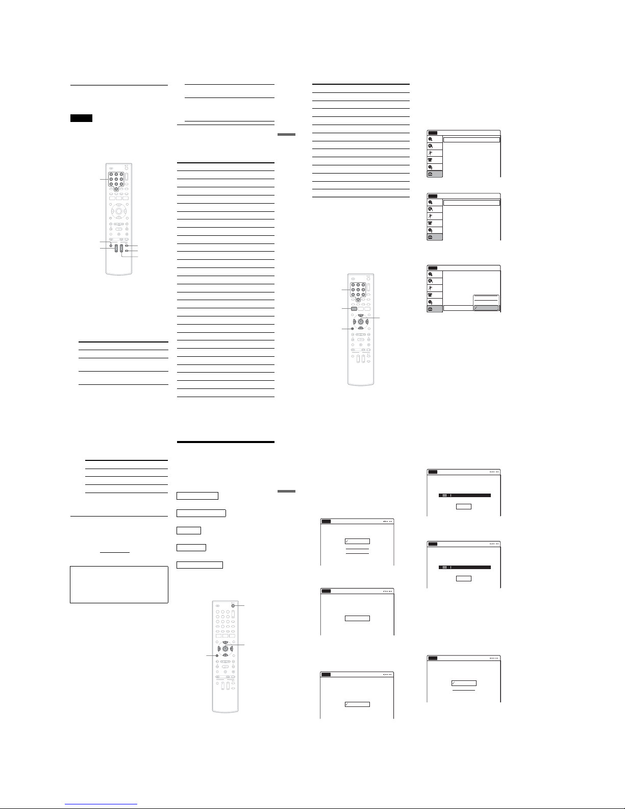
28
If you have a Sony DVD player or
more than one Sony DVD recorder
If the supplied remote interferes with your other
Sony DVD recorder or player, set th e command
mode number for this recorder and the supplied
remote to one that differs from the other Sony
DVD recorder or player after you have completed
“Step 7: Easy Setup.”
The default command mode setting for this
recorder and the supplied remote is DVD 3.
1 Check that Easy Setup (page 29) has be en
finished. If Easy Setup has not been
finished, first perform Easy Setup.
2 Press SYSTEM MENU.
The System Menu appears.
3 Select “Setup,” and press ENTER.
4 Select “Options,” and press ENTER.
5 Select “Command Mode,” and press
ENTER.
6 Select a command mode (“DVD 1,” “DVD
2,” or “DVD 3”), and press ENTER.
7 Set the command mode for the remote so it
matches the command mode for the
recorder you set above.
Follow the steps below to set the command
mode on the remote.
A Hold d own ENTER.
Sampo 12
Samsung 03, 04, 12, 20
Sanyo 11, 14
Scott 12
Sears 07, 10 , 11
Sharp 03, 05, 18
Sylvania 08, 12
Teknika 03, 08, 14
Toshiba 07, 18
Wards 03, 04, 12
Yorx 12
Zenith 14, 15
Manufacturer Code number
11 22 33
44 55 66
77 880099
SYSTEM
MENU
M/m/</,,
ENTER
O RETURN
Number
buttons
10:10 AM
Tuner Preset
Clock Set
Video
Audio
Features
Options
Easy Setup
Setup
Disc Setting
Edit
Title List
Timer
Setup
No Disc
DV/D8 Dubbing
Options
Language
Parental
Digital Wide Control
Caption Service
Caption Setting
Front Display
Command Mode
Factory Setting
: 16:9
: Off
: Auto
: DVD 3
10:10 AM
Setup
Disc Setting
Edit
Title List
Timer
No Disc
DV/D8 Dubbing
Options
10:10 AM
Setup
Disc Setting
Edit
Title List
Timer
No Disc
Language
Parental
Digital Wide Control
Caption Service
Caption Setting
Front Display
Command Mode
Factory Setting
: 16:9
: Off
: Auto
: DVD 3
DV/D8 Dubbing
DVD 1
DVD 2
DVD 3
29
Hookups and Settings
B While holding down ENTER, enter the
command mode code number usi ng the
number buttons.
C Hold down both the number buttons and
ENTER at the same time for more than
three seconds.
To return to the previous display
Press O RETURN.
To check the command mode for the recor der
Press x (stop) on the recorder when the recorder
is turned off. The command mode for the reco rder
appears in the front panel display.
Step 7: Easy Setup
Follow the steps below to make the minimum
number of basic adjustments for using the
recorder. If you do not complete Easy Setup, it
will appear each time you turn on your recorder.
Settings are made in the following order.
m
m
m
m
m
1
Turn on the TV.
2
Press "/1.
The recorder turns on.
Command Mode Code number
DVD1 number button 1
DVD2 number button 2
DVD3 number button 3
If the command mode for the recorder has not
been changed, set the command mode for the
remote to the default setting of DVD3. If the
command mode for the remote is changed to
DVD1 or DVD2, you will be unable to operate
this recorder.
OSD Language Setup
Tuner and Channel Setup
Clock Setup
TV Type Setup
Audio Connection Setup
Finished!
11 22 33
44 55 66
77 880099
M/m/</,,
ENTER
O RETURN
"/1
,continued
30
3 Switch the input selector on your TV so t hat
the signal from the recorder appears on
your TV screen.
“Initial setting necessary to op erate the DVD
recorder will be made. You can change them
later using setup.” appears.
•If this message does not appear, select “Easy
Setup” in the “Setup” display to run Easy
Setup (page 88).
4 Press ENTER.
The setup display for selecting the language
used in the on-screen display ap pears.
5 Select a language, and press ENTER.
The display to confirm scanning appears.
6 Press ENTER.
The setup display for channel setting appears.
7 Select whether or not you have a cable
connection.
If you use an antenna only (no cable TV),
select “Antenna.”
For all other connections, se lect “Cable.”
8 Press ENTER.
The Tuner Preset function automatically starts
searching for all of receivable analog channels
and presets them.
After searching for analog channels is
complete, receivable digital channels are then
searched for automatically.
•This may take 40 minutes or more to
complete.
•If you press ENTER during search for
channels, the recorder will stop searching
for channels and advance the next step.
To set analog channels manually, see page 7 7.
After the Tuner Preset is finished, the setup
display for clock setting appears.
9 Select a method for setting the clock.
English
Français
Español
Easy Setup
Select the screen language.
No Disc
Easy Setup
No Disc
Press [ENTER] to start scanning
Digital and Analog channels.
Start
Select the way in which you will receive
channels.
Antenna
Cable
Easy Setup
No Disc
Searching for receivable Analog channels.
Please wait.
Easy Setup
No Disc
Stop
Searching for receivable Digital channels.
Please wait.
Allow 40+ minutes for completion.
To stop searching, press [Enter].
Easy Setup
No Disc
Stop
Select a method for setting the clock.
If you select "Auto", this recorder will look
for a time signal when you turn it off.
Auto
Manual
Easy Setup
No Disc
1-7
31
Hookups and Settings
10
Select “Manual,” and press ENTER.
Press M/m to set the month and press ,. Set
the day, year, hour, minutes, and AM/PM in
the same way, then press ENTE R. The day of
the week is set automatically.
•If you used antenna hookup C (p age 20),
you can select “Auto.” The recorder will
automatically search for a channel that
carries a time signal when you turn off the
recorder after finishing Easy Setup.
The setup display for selecting the picture size
of the connected TV appears.
11
Select the setting that matches your TV
type.
“16:9”: For wide-screen TVs or stan dard TVs
with a wide screen mode.
“4:3 Letter Box”: For standard TVs.
Displays “wide screen” pictures with b ands
on the upper and lower sections of the screen.
“4:3 Pan Scan”: For standard TVs.
Automatically displays “wide screen”
pictures on the entire screen and cuts off the
sections that do not fit.
For details, see “Video Settings (Video)” on
page 79.
12
Press ENTER.
The setup display for selecting the type of
Dolby Digital signal appears.
13
Select the type of Dolby Digital signal you
want to send to your amplifier (receiver).
If your AV amplifier (receiver) has a Dolby
Digital decoder, select “Dolby Digital.”
Otherwise, select “D-PCM.”
14
Press ENTER.
The setup display for selecting the type of
DTS signal appears.
15
Select whether or not you want to send a
DTS signal to your amplifier (receiver),
and press ENTER.
If your AV amplifier (receiver) has a DTS
decoder, select “On.” Otherwise, select “Off.”
16
Press ENTER when “Finish” appears.
Easy Setup is finished. All connections and
setup operations are complete.
To return to the previous display
Press O RETURN.
z Hint
If you want to run Easy Setup again, select “Ea sy Setup”
in the “Setup” display (page 88).
Note
To record TV programs using the timer, you must set the
clock accurately.
16 : 9
4 : 3 Letter Box
4 : 3 Pan Scan
Easy Setup
Select your TV screen type.
10:10 AM
No Disc
D-PCM
Dolby Digital
Easy Setup
Dolby Digital
10:10 AM
No Disc
On
Off
Easy Setup
DTS
10:10 AM
No Disc
Finish
Easy Setup
Easy Setup is finished.
10:10 AM
No Disc
32
Connecting a VCR or Similar Device
After disconnecting the recorder’s power cord from an AC outlet, connect a VCR or similar recording
device to the LINE IN jacks of this recorder. See also the instruction manual supplied with the connected
equipment.
If you connect equipm ent that has a timer function, you can use the Synchro Rec function ( page 53). In
this case, connect the equipment to the LINE 1 IN jacks (page 33).
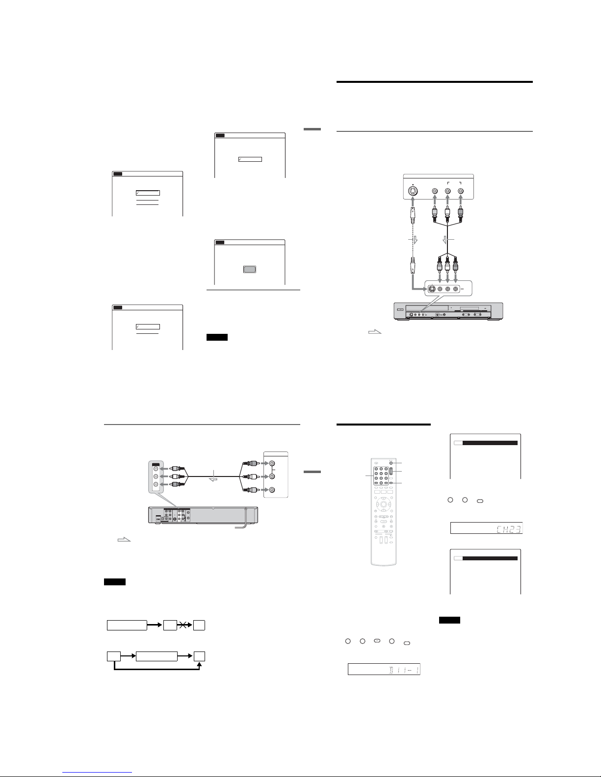
Connecting to the LINE 2 IN jacks on the front panel
Connect a VCR or simila r device to the LINE 2 IN jacks of th is recorder. If the equipment ha s an S video
jack, you can use an S video cord ( not supplied) instead of the yellow (vide o) plug of the audio/video cord.
Do not connect to the S VIDEO and yellow VIDEO jacks at the same time.
You can connect a second DVD player and record DVDs.
HDMI
DV IN
L(MONO) AUDIO RVIDEOS VIDEO
LINE-2 IN
ONE-TOUCH DUBBING
+
CHANNEL
-
S VIDEO
AUDIO
LR
VIDEO
OUTPUT
L(MONO) AUDIO RVIDEOS VIDEO
LINE-2 IN
VCR, etc.
S video cord
(not supplied)
Audio/video cord
(not supplied)
DVD recorder
to LINE 2 IN
: Signal flow
33
Hookups and Settings
Connecting to the LINE 1 IN jacks
You can connect a VCR or similar device.
z Hints
•When the connected equipment outputs only monaural sound, connect an audio cord to the white LINE IN AUDIO L
(mono) jack.
•To record from connected equipment, select an input source (LINE1 or LINE2) to match the jack you connected to
(page 55).
Notes
•Do not connect more than one type of video cord betwee n the recorder and your TV at the same time.
•Pictures containing copy protection signals that prohibit any copying cannot be record ed. You cannot dub from DVD
VIDEOs to this recorder.
•Do not con nect the output jack of this recorder to another equipment’s input jack with the other equipment’s output
jack connected to the input jack of this recorder. Noise (feedback) may result.
• If you pass the recorder signals via the VCR, you may not receive a clear image on your TV screen.
Be sure to connect your VCR to the DVD recorder and your TV in the order shown below. To watch video tapes,
watch the tapes through a second line input on your TV.
L
R
VIDEO
AUDIO
LINE OUT VHF/UHF
VIDEO
YL
P
B
R
P
R
AUDIO
LINE 1 IN
AUDIO OUT S VIDEO OUT
COMPONENT
VIDEO OUT
DIGITAL AUDIO OUT
OPTICAL COAXIAL
HDMI OUT
IN
OUT
LINE OUTPUT
AUDIO
R
L
VIDEO
VIDEO
LINE 1 IN
AUDIO
Audio/video cord
(not supplied)
VCR, etc.
: Signal flow
to LINE 1 IN
DVD recorder
VCRDVD recorder TV
VCR DVD recorder TV
Line input 1
Line input 2
34
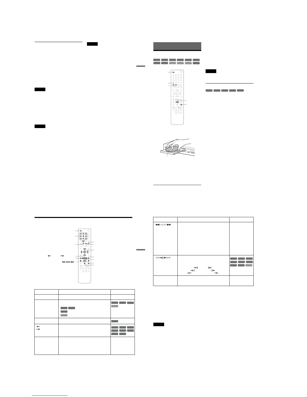
Watching TV
By connecting your TV to this recorder, you can
watch digital and analog channels on your TV.
1
Turn on this recorder.
2
Turn on the TV and switch the TV's input
selector so that the signa l from the
recorder appears on your TV screen.
3
Press DIGITAL/ANALOG to select the
broadcast, digital or an alog.
4
Press the number buttons to sele ct the
channel you want to watch, and press SE T.
For example, to select digital channel number
D11.1
t t t t
The front panel displa y should show the
following:
The TV screen should show the following:
For example, to select analog channel number
Ch23
t t
The front panel display should show the
following:
The TV screen should show the following:
z Hint
You can also select a channel using the CH +/– button.
Notes
• If you do not press the SET button after sett ing the
number buttons, the channel is not changed.
•When you change an analog channel to a digital
channel, press the DIGITAL/ANALOG button. Even if
you press the ·(dot) button, an analog channel is not
changed to digital.
• If you receive new digital channels, or the black screen
appears on your TV, set “Auto Preset” of “Tuner
Preset” again (page 76).
•Som e digital channels do not have a “·” (dot). Refer to
the TV program.
•Confirm the digital broadcast content of the channel
number received before timer recording. If the recorder
receives a digital broadcast without channel numbe r
information, the recorder assigns the channel number
automatically.
11 22 33
44 55 66
77 880099
"/1
Number
buttons,
SET,
· (dot)
DIGITAL/
ANALOG
CH +/–
11 11 11
SET
SP D11.1
No Disc
22 33
SET
SP Ch23
No Disc
1-8
35
Hookups and Settings
Enjoying Digital Broadcasts
You can enjoy digital broadcasts. Di gital
broadcasts are better quality, mo re varied, and
more controllable than analog broadcasts. By
using digital functions such as rating , closed
caption, or audio setting, you can m ake various
adjustments to enjoy a digital br oadcast.
To use the digital rating
Digital Rating is controlled by the Rating Region
Table (RRT). The RRT is decided by the
broadcaster. This table can be use d as parental
ratings. For details, see “Digital Rating” of
“Parental” in “Options” setu p (page 85).
Note
This recorder cannot receive the program guide table,
therefore, you cannot set the rating in adva nce. But as the
dimension that was set once is memorized, the future
program will be able to refer this setting.
To use digital closed captions
Digital Closed Caption supports programs that
have the caption service. If the s upport service
number is selected, closed captions appear on
screen. For details, see “Caption Service” in
“Options” setup (page 87).
Note
Digital closed captions cannot be recorded.
To select digital audio settings
You can adjust audio settings using the OPTIONS
menu.
1
Press OPTIONS.
2
Press M/m to select “ Audio.”
3
Press </, to select the stream you want to
listen to, then press ENTER.
The contents of a stream depend s on the
program.
Depending on the program, you can switch
the left and right sound using the AUDIO
button.
Notes
•Only the selected audio can be recorded. When
recording with the timer, “Stream 1” is usually
recorded.
•Dolby Digital (5.1ch) signals will be automaticall y
converted to Downmix (2ch) signal and recorded.
•The HDMI OUT jack cannot output Dol by Digital
signals for digital broadcasts. To hear Dolby Digital,
use the DIGITAL AUDIO OUT jacks.
• HD (Hi gh Definition) signal through this recorder is
converted to SD (Standard Definiti on) signal. You
cannot record in HD (High Definition).
36
Playback
Playing Discs
1
Press Z OPEN/CLOSE, and place a disc on
the disc tray.
2 Press Z OPEN/CLOSE to close the disc
tray.
Wait until “LOAD” disappears from the front
panel display.
3 Press H PLAY.
Playback starts.
To stop playback
Press x STOP.
z Hints
•You can play DATA CDs or DATA DVDs with MP3
audio tracks or JPEG image files (pages 42 or 43).
• If you insert a DVD VIDEO, VIDEO CD, or CD,
playback starts automatically depending on the disc.
•When playing a DVD+RW, DVD-RW, DVD+R,
DVD-R, and DVD-RAM, you can select the title from
the Title List menu (page 40).
•When using a DVD-RAM with a cartridge, remove the
disc from the cartridge.
Note
To play a disc recorded with other equipment on this
recorder, finalize the disc on the recording equipment
first.
Using the DVD’s Menu
When you play a DVD VIDEO, or a finalized
DVD+RW, DVD-RW (Video mode), DVD+R, or
DVD-R (Video mode), you can display the disc’s
menu by pressing TOP MENU or MENU.
+
RW
+
R
DVD
VCD
CD
-
RW
VR
-
RW
Video
DATA DVD
DATA CD
-
R
VR
-
R
Video
RAM
11 22 33
44 55 66
77 880099
x STOP
Z OPEN/
CLOSE
H PLAY
TOP MENU
MENU
D
V
I
N
L
(
M
O
N
O
)
A
U
D
I
O
R
V
ID
E
O
S
V
ID
E
O
L
IN
E
-
2
I
N
O
N
E
-
T
O
U
C
H
D
U
B
B
I
N
G
Playback side facing down
+
RW
+
R
DVD
-
RW
Video
+
R
-
R
Video
37
Playback
Playback Options
Button Operation Disc
Z
OPEN/CLOSE Stops playing and opens the disc tray. All discs
AUDIO Selects one of the audio tracks recorded on the disc
when pressed repeatedly.
: Selects the main or sub sound.
: Selects the audio source.
: Selects stereo or monaural audio tracks.
SUBTITLE Selects a subtitle language w hen pressed repeatedly.
.
REPLAY/
ADVANCE
•Replays or briefly fast forwards a scene when
pressed during playback.
•Goes to the previous or next frame when pressed
during pause mode.
. PREV/
NEXT >
•Goes to t he beginning of the current or next title/
chapter/scene/track and starts playback when
pressed during playback.
•Goes to t he beginning of the previous title/chapter/
scene/track when .PREV is pressed within three
seconds after starting a title/chapter/scene/track.
All discs
11 22 33
44 55 66
77 880099
Z OPEN/CLOSE
X PAUSE
. PREV
REPLAY/ ADVANCE
x STOP
H PLAY
M/m/</,,
ENTER
Number buttons
> NEXT
MENU
AUDIO
SUBTITLE
-
RW
VR
-
R
VR
DVD
VCD
DVD
VCD
-
RW
VR
-
R
VR
DVD
+
RW
+
R
DVD
-
R
Video
RAM
RAM
-
RW
VR
-
RW
Video
-
R
VR
,continued
38
To resume normal playback after pl aying at various speeds, press H PLAY .
z Hints
•You can change playback options, such as subtitle,
audio track, etc., using the OPTIONS men u (page 11).
•During playback or pause mode, the recorder’s m/
M buttons and the remote’s .PREV/>NEXT
buttons work the same way (page 37). Hold the buttons
down during playback to fast forward or fast reve rse. In
pause mode, you can play in slow motion. Three speeds
are available, depending on the duration of the press.
•See “DVD Audio/Subtitle Language” on page 102 for
the meaning of the language abbre viation.
Notes
• If y ou pause playback of a CD, or DATA CD/DATA
DVD containing MP3 audio tracks, playback will not
start until you press H PLAY or X PAUSE.
•Sound will be interrupted during Scan Audio
(page 39).
Notes on playing DTS soundtracks on a CD
When playing DTS-encoded CDs, excessive noise
will be heard from the analog stereo jacks. To
avoid possible damage to the audio system, the
consumer should take proper precautio ns when
the analog stereo jacks of the recorder are
connected to an amplification system. To enjoy
DTS Digital Surround™ playback, an external
5.1-channel decoder system must be connected to
the digital jack of the recorder.
Notes on playing DVDs with a DTS soundtrack
DTS audio signals are output only throug h the
DIGITAL AUDIO OUT (COAXIAL or
OPTICAL)/HDMI OUT jacks.
When you play a DVD with DTS soundtracks, set
“Digital Out” – “DTS” to “On” of “Audio” in the
“Setup” display (page 81).
If you connect the recorder to audio equipme nt
without a DTS decoder, do not set “DTS” to “On”
in “Audio” setup. A loud noise (or no sound) may
come out from the speakers, which might disturb
your ears or cause damage to the speakers.
(fast reverse/fast
forward)
Fast reverses or fast forwards the disc when pressed
during playback.
Search speed changes with each press:
fast reverse fast forward
FR1 T t FF1
*1
FR2*2 T T t t FF2
*2
FR3*3 T T T t t t FF3
*3
All discs
*1
FF1 with sound
(Scan Audio) is
available for DVDs
with Dolby Digital
soundtracks.
*2
FR2 and FF2 are not
available for MP3.
*3
FR3 and FF3 are only
available for DVDs
and VIDEO CDs.
(slow)
Plays in slow motion when pressed in pause mode.
Playback speed changes with each press:
reverse slow motion forward slow motion
T t
T T t t
T T T t t t
*Playback direction
only
X PAUSE Pauses playback.
If you pause playback for more than five minutes,
playback starts automatically.
All discs
Button Operation Disc
VCD
+
RW
+
R
-
RWVR-RWVideo
DVD
-
RVR
-
RVideo
RAM
*
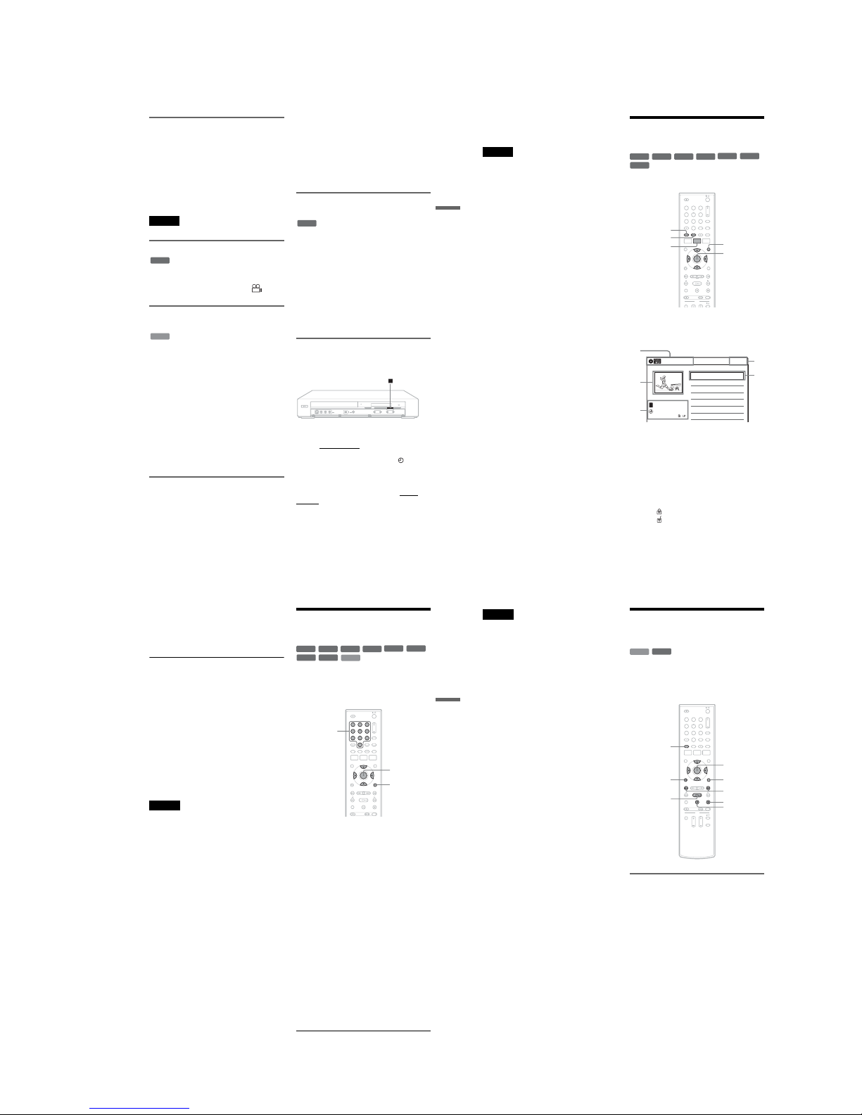
1-9
39
Playback
Playing quickly with sound (Scan
Audio)
(DVDs with Dolby Digital soundtracks
only)
You can play quickly with dialog or sound during
FF1 fast-forward of a DVD with Dolby Digital
soundtracks. Simply press M during playback.
z Hint
To turn off the Scan Audio function, set “Scan Audio” of
“Audio” to “Off” in the “Setup” displ ay (page 82).
Note
Sound will be interrupted during Scan Audio.
Changing angles
You can enjoy various angles using the OPTIONS
menu (page 11). If various angles (multi-angles)
for a scene are recorded on the disc, “ ”
appears in the front panel disp lay.
Playing VIDEO CDs with PBC
functions
PBC (Playback Control) allows you t o play
VIDEO CDs interactively using a menu on your
TV screen.
When you start playing a VIDEO CD with PBC
functions, a menu appears.
Select an item using the number bu ttons and press
ENTER. Then follow the instructions in the menu
(press H PLAY when “Press SELECT”
appears).
Operations differ depending on the disc. See the
instructions supplied with the disc.
To cancel PBC Playback
Press MENU to display “Menu: O ff.” To use the
PBC functions, press MENU agai n to display
“Menu:On.”
Resuming playback from the point
where you stopped the disc (Resume
Play)
Press H PLAY again after stopping a di sc to
resume playback from the same point.
To start from the beginning, press x STOP twice,
and press H PLAY.
The point where you stopped playing is cleared
when:
– you open the disc tray.
– you play another title.
– you switch the Title List menu to original or
Playlist (DVD-RW (VR mode)/DVD-R (VR
mode)/DVD-RAM only).
– you edit the title after stopping playback.
– you make a recording.
Playing restricted DVDs (Parental
Control)
If you play a restricted DVD, a message appears
asking whether you want to override the
restriction.
1
Select “OK” and press ENTER.
The display for entering your password
appears.
2
Enter your four digit password using the
number buttons.
The recorder starts playback.
To register or change the password, see “DVD
VIDEO” on page 86.
Locking the recorder (Child Lock)
You can lock all of the buttons on the recorder so
that the settings are not canceled by mistake.
With the recorder turned on and stopped, hol d
down x on the recorder
for more than ten seconds.
The recorder turns off and “CHILD LOCK”
appears in the front panel display. The indicator
remains lit if there is a timer setting. The recorder
will not work except for timer recordings.
To unlock the recorder, hold down x on the
recorder until “CHILD LOCK” disappears from
the front panel display. The recorder is unlocked
and turns on.
DVD
VCD
DVD
+
-
,continued
40
To stop timer recording while the recorder is
locked, press x twice. The recording stops and the
recorder is unloc ked.
Note
The recorder will be unlocked when you stop timer
recording by pressing x.
Playing a Title From the
Title List
The Title List menu displays the program titles on
the disc.
1
Place a disc on the disc tray.
2
Press TITLE LIST.
Example: DVD-RW (VR mode)
A Disc type:
Displays a disc type.
Also displays the title type (original or
Playlist) for DVD-RWs (VR mode),
DVD-Rs (VR mode), and DVD-RAMs.
B Movie thumbnail image
C Title information:
Displays the title number, title name,
recording date, and recording mo de.
“” indicates a protected title, while
“” indicates unprotected.
D Clock
+
RW
+
R
-
RW
VR
-
RW
Video
RAM
-
R
VR
-
R
Video
11 22 33
44 55 66
77 880099
TOP MENU
M/m/</,,
ENTER
MENU
TITLE LIST
ORIGINAL/
PLAYLIST
10:10 AM
01 >01:29:03
02 >00:31:23
03 >01:59:00
04 >00:58:56
08:00 PM
T
No. Title Length Edit
Title List (Original)
1/4
D11.1
D22.2
Ch 23
Ch 66
D11.1
May/02/2007
1
2
3
4
3
41
Playback
3 Select the title, and press ENTER.
The sub-menu appears.
4 Select “Play,” and press ENTER.
Playback starts from the select ed title on the
disc.
About the Title List for DVD-RWs (VR mode)
and DVD-Rs (VR mode)
You can switch the Title List to show an orig inal
or Playlist.
While the Title List menu is turned on, press
ORIGINAL/PLAYLIST repeatedly to select
either “Title List (Original)” or “Playlist.”
For details, see “Edit options for DVD-RWs (VR
mode)/DVD-Rs (VR mode)” on page 57.
To turn off the Title List
Press TITLE LIST.
z Hint
You can also switch the Title List of DVD-RAMs to
show an original or Playlist.
Notes
•The Title List does not appear for DVD-RWs (Video
mode), DVD+Rs, or DVD-Rs (Video mode) that have
been finalized. To view a title, press TOP MENU or
MENU (page 36).
•The Title List may not appear for discs created on other
DVD recorders.
•Letters that cannot be displayed are replaced with “*.”
Searching for a Title/
Chapter/Track, etc.
You can search a DVD by title or chapter, and
VIDEO CD by track or scene. As titles and tracks
are assigned individual numbers on the disc, select
the title or track by entering its number. You can
also search for a scene using the time code.
1 Press OPTIONS during playback.
The OPTIONS menu appears.
2 Select a search method.
“Title” (for DVDs)
“Chapter” (for DVDs)
“Track” (for VIDEO CDs with PBC function
off)
“Time” (for DVDs/VIDEO CDs with PBC
function off): Searches for a starting point
using the time code.
3
Press M/m/</, to select the number of
the title, chapter, track, etc., you want, or
press the number buttons to enter the time
code.
For example: “Time”
To find a scene at 2 hours, 5 minutes, and 20
seconds, enter “20520.”
If you make a mistake, wait a moment until
the display returns to the elapsed playing time
display, then select another number.
4 Press ENTER.
The recorder starts playback from the selected
point.
To turn off the display, press OPTIONS.
+
RW
+
R
VCD
-
RWVR-RWVideo
RAMDVD
-
RVR
-
RVideo
11 22 33
44 55 66
77 880099
OPTIONS
M/m/</,,
ENTER
Number
buttons
,continued
42
Notes
•Dependi ng on the disc, you may not be able to use the
OPTIONS menu to search for a title/chapter/track, or
enter the time code for a playback point.
•When playing a Playlist title, you may not be able to
search for a scene using the time code.
Playing MP3 Audio Tracks
and JPEG Image Files
You can play DATA CDs (CD-ROMs/CD-Rs/
CD-RWs)/DATA DVDs (DVD-ROMs/
DVD+RWs/DVD-RWs/DVD+Rs/DVD-Rs) that
contain MP3 audio tracks or JPEG image files.
Playing MP3 audio tracks
You can play MP3 audio tracks on DATA CDs or
DATA DVDs.
1
Place a DATA CD/DATA DVD on the disc
tray.
When you insert a DATA CD/DATA DVD
containing MP3 audio tracks and JPEG image
files, the display for selecting a media type
appears. When you select “Mix,” you can
enjoy a slide show with sound (page 44).
DATA CD
DATA DVD
11 22 33
44 55 66
77 880099
H PLAY
O RETURN
M/m/</,,
ENTER
./>
TOP MENU
x STOP
OPTIONS
X PAUSE
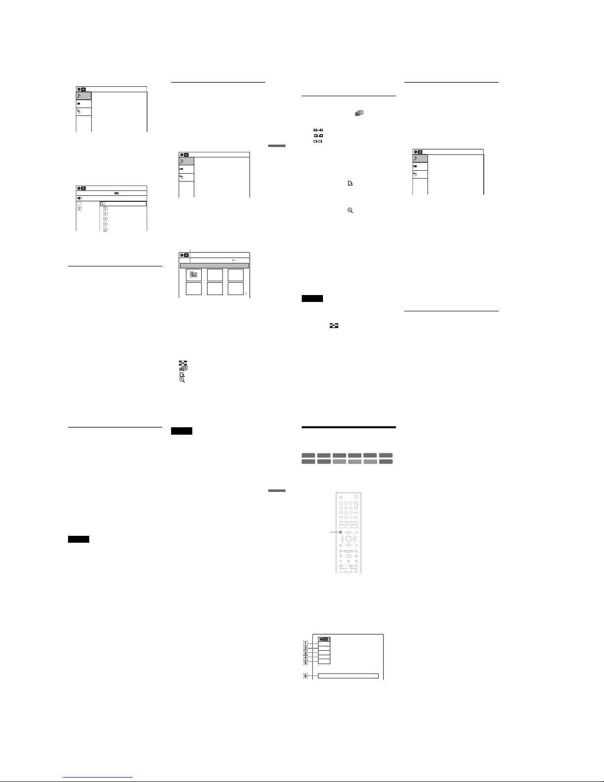
1-10
43
Playback
If you insert a DATA CD/DATA DVD
containing only MP3 audio tracks, the
“Music” display appears. Go to step 3.
2
Select “Music,” and press ENTER.
The “Music” display appears.
3
Select an album, and press ENTER.
4
Select a track, and press ENTER.
Playback starts from the selected track.
When a track or album is being played, the
title is shown in a box.
To stop playback
Press x STOP.
To pause playback
Press X PAUSE.
To restart playback, press H PLAY or X
PAUSE.
To return to the previous display
Press O RETURN.
To switch between MP3 audio tr acks and JPEG
image files
Press x STOP, and press TOP MENU.
z Hint
When playback of all the MP3 audio tracks within the
album finishes, the recorder stops.
Playing JPEG image files
You can play JPEG image file s on DATA CDs or
DATA DVDs.
1
Place a DATA CD/DATA DVD on the disc
tray.
When you insert a DATA CD/DATA DVD
containing MP3 audio tracks and JPEG image
files, the display for selecting a media type
appears.
When you select “Mix,” you can
enjoy a slide show with sound (page 44).
If you insert a DATA CD/DATA DVD
containing only JPEG image files, the
“Photo” display appears. Go to step 3.
2
Select “Photo,” and press ENTER.
The “Photo” display appears.
3
Select a folder, and press ENTER.
To display the previous or next page, press
./>.
4
Select an image file, and press ENTER.
The selected image is displayed over the
entire screen.
To display the previous or next image, press
./>.
The following menu icons appear in the upper
part of the screen.
: Returns to the “Photo” dis play.
: Starts the slide show (page 44).
: Rotates the image (page 44).
: Zooms the image (page 44 ).
10:10 AM
Photo
Music
Mix
Press ENTER :
Music menu for this disc.
Stop 00:00:00
Prev Directory
01-Track1.mp3
02-Track2.mp3
03-Track3.mp3
04-Track4.mp3
05-Track5.mp3
MP3_001
0/9
10:10 AM
Music
Surround:Off
10:10 AM
Photo
Music
Press ENTER :
Mix
Music menu for this disc.
Slideshow
\abc\defg
Page 1 / 2
10:10 AM
Photo
Directory information
,continued
44
Press OPTIONS to turn on/off the menu
icons.
To play the slide show
1
Press </, to select “ ,” and press
ENTER.
The “Slideshow Speed” menu app ears.
“”: Slow
“”: Normal
“”: Fast
2
Press </, to select the desired play sp eed,
and press ENTER.
The slide show starts from the sele cted image.
To stop playing, press x STOP.
To rotate the selected image
Press </, to sele ct “,” and press ENTER.
Each time you press ENTER, the image turns
clockwise by 90°.
To zoom in an image
Press </, to sele ct “,” and press ENTER.
Each time you press ENTER, the magnification
changes as follows:
2 u t 4 u t 2 u t normal
To return to the previous display
Press O RETURN.
To switch between MP3 audio tra cks and JPEG
image files
Press x STOP, and press TOP MENU.
z Hint
You can also start the slide show by pressing H PLAY
in step 4 above.
Notes
•You cannot use M/m/</, to move the image within
the screen while zoomin g.
•Slide show can play in only one direction.
•You cannot rotate or zoom during slide show.
• If you sel ect “ ” in the rotated imag e display, the
images in the “Photo” display will not be rot ated.
Enjoying a slide show with sound
When a disc contains both MP3 audio track s and
JPEG image files, you can enjoy a slide show with
sound.
1 Insert a DATA CD/DATA DVD containing
both the MP3 audio tracks and JPEG image
files.
The display for selecting a media type
appears.
2 Select “Mix,” and press ENTER.
The “Music” display appears.
3 Select an album, and press ENTER.
4 Select a track, and press ENTER.
Playback starts from the selected track, and
the display asks for confirmation.
5 Select “Yes,” and press ENTER.
The “Photo” display appears.
6 Select the folder you want to view, and
press ENTER.
7 Press H PLAY to start the slide show.
The “Slideshow Speed” menu appears.
8 Press </, to select the slide show
speed, and press ENTER.
The slide show starts with sound.
To stop the slide show
Press x STOP.
z Hints
•When playing JPEG images, you can also use the onscreen menu. For details, see “Playing JPEG image
files” (page 43).
•The slide show is played repeatedly until MP3
playback stops.
10:10 AM
Photo
Music
Press ENTER :
Mix
Music menu for this disc.
45
Playback
About MP3 audio tracks and JPEG
image files
MP3 is audio compression technology that
satisfies the ISO/IEC MPEG regulations.
JPEG is image compression technology.
You can play back DATA CDs (CD-ROMs/CDRs/CD-RWs) or DATA DVDs (DVD-ROMs/
DVD+RWs/DVD-RWs/DVD+Rs/DVD-Rs)
recorded in MP3 (MPEG1 Au dio Layer 3) and
JPEG format.
However, this recorder only plays DATA CDs
whose logical format is I SO9660 Level 1/Level 2
or Joliet, and DATA DVDs of Universal Disk
Format (UDF).
See the instructions supplied with the disc drives
and the recording software (not supplied) for
details on the recording format.
Note
The recorder may not be able to play some DATA CDs
or DATA DVDs created in the Packet Write format.
MP3 audio tracks or JPEG image files that the
recorder can play
The recorder can play the following tracks and
files:
–MP3 (MPE G1 Audio Layer 3) audio tracks.
–MP3 audio tracks with the extensi on “.MP3.”
–JPEG image files with the extension “.JPEG” or
“.JPG.”
z Hints
• If you add n umbers (01, 02, 03, etc.) to the front of the
file names, the files will be played in that order.
•Since a disc with many trees takes longer to start
playback, it is recommended that you create albums
with no more than two trees.
Notes
•Some DATA CDs or DATA DVDs cannot be played
on this recorder depending on file format.
•Only on e session of a multi-session DATA DVD can
be played back.
•Only a lphabet and numbers can be used for album or
track names. Anything else is displayed as an asterisk.
•The recorder will play any data with the extension
“.MP3,” even if they are not in MP3 format. Playing
such data may generate a loud noise which could
damage your speaker system.
•The recorder does not conform to audio tracks in
MP3PRO format.
•The recorder can recognize up to 499 MP 3 audio tracks
within a single album. The recorder ma y not recognize
some discs depending on the recording de vice used for
recording or the disc condition.
•The recorder can play MP3 audio tracks recorded in the
following sampling frequencies: 32 kHz, 44.1 kHz,
48 kHz.
•ID3 tags canno t be displayed.
•If you add the extension “.JPG” or “.JPEG” to data not
in JPEG format, a message appears indicating that the
format is not supported.
•Dep ending on the disc, or the size or total n umber of
files, playback may take some time to start.
•The recorder can recognize up to 999 JPEG image files
within a single folder. The recorder may not recognize
some discs depending on the recording de vice used for
recording or the disc condition.
•Progressive and lossless compression JPEG image files
are not supported.
•The image size that the reco rder can display is limited
to width 32 - 7680 pixels by height 32 - 8192 pixels.
•JPEG image files that conform to the DCF* image file
format are not supported.
*“Design rule for Camera File system”: Image standards
for digital ca meras regulated by JEI TA (Japan
Electronics and Information Technology Industries
Association).
46
Displaying the Playing Time
and Play Information
You can check disc information, such as playing
time, recording mode, and remaining disc space.
Press DISPLAY.
The information display appear s.
Each time you press the button, the display
changes as follows:
Disc information/date and time
m
Disc information only
m
No display
A Playing status
B Playing time
C Recording mode
D Remaining di sc space (in stop mode)
Remaining time of the current title (during
playback
*1
)
E Channel or input source
*2
F Date and time
*1
Also appears in stop mode with Resume Play
activated (page 39).
*2
Title type (original or Playlist) for DVD-RWs (VR
mode)/DVD-Rs (VR mode)/DVD-RAMs.
+
R
DVD
VCD
CD
-
RWVR-RWVideo
+
RW
DATA CD
DATA DVD
RAM
-
RVR
-
RVideo
11 22 33
44 55 66
77 880099
DISPLAY
Wed May 02. 2007 10:10 AM
Play
0:05:30
HQ
Rem 00:25
Original
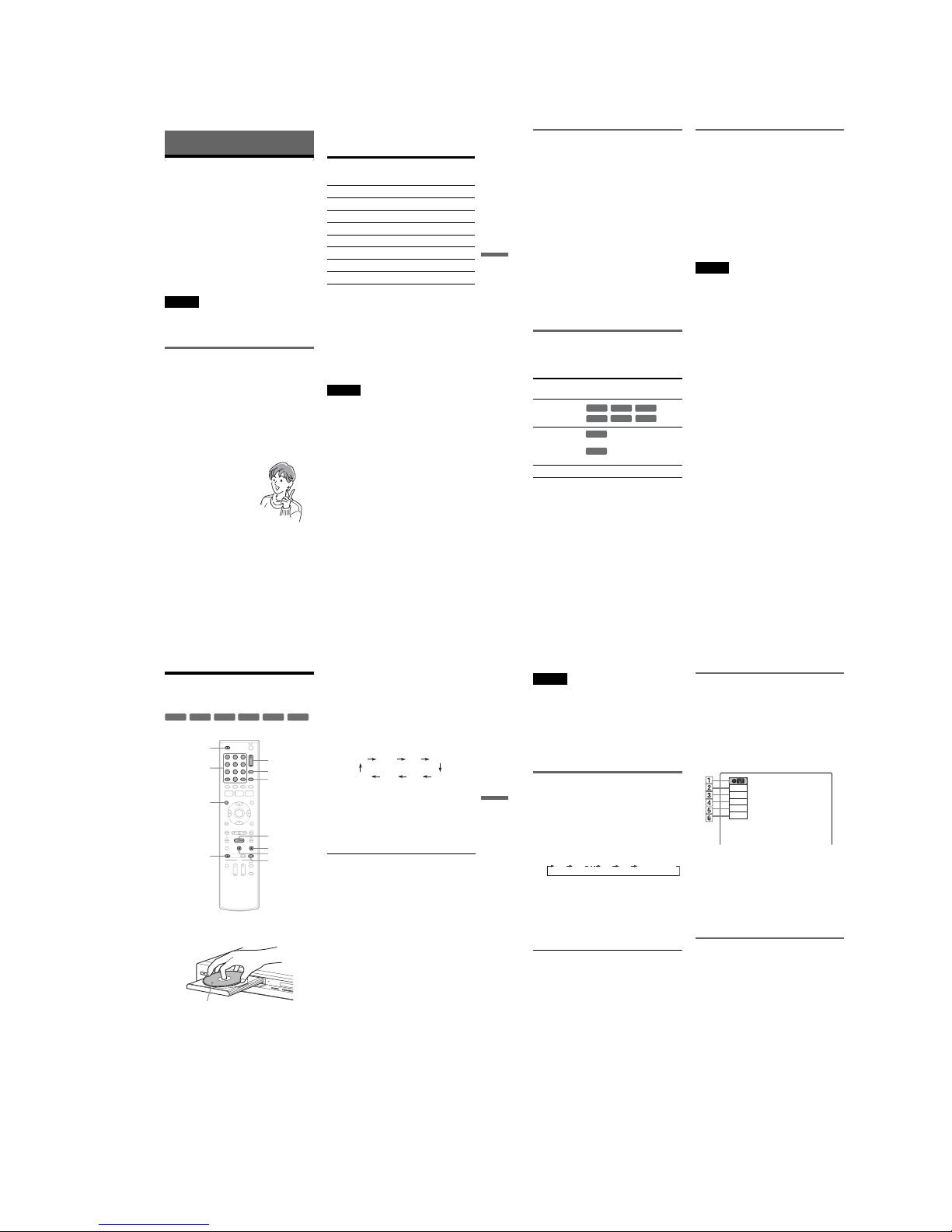
1-11
47
Recording
Recording
Before Recording
Before you start recording…
•This recorder can record o n various disc types.
Select the disc type according to your need s
(page 12).
•Check that the disc has enough available sp ace
for the recording (page 46). For DVD+RWs or
DVD-RWs, you can free up disc space by
erasing titles (page 58).
z Hint
To play a disc recorded with this recorder on other
equipment, finalize the disc (page 69).
Notes
•Timer recordings will start with or without the recorder
turned on. The recorder automatically turns off after a
recording has finished.
•This recorder records at ×1 speed.
Recording mode
Like the SP or EP recording mode of VCRs, this
recorder has eight differe nt recording modes.
Select a recording mode according to the time and
picture quality you need. For exam ple, if picture
quality is your top priority, select “HQ” (high
quality). If recording time is your priority, “SLP”
can be a possible choice.
Press REC MODE repeatedly to switch the
recording modes.
Recording mode and recording time
The following table is an approximate guide for
the recording time on a single DVD (4.7 GB).
z Hint
The approximate recording time for DVD+R DL
(Double Layer) discs is as follows:
HQ: 1 hour 48 minutes
HSP: 2 hours 42 minutes
SP: 3 hours 37 minutes
LSP: 4 hours 31 minutes
ESP: 5 hours 25 minutes
LP: 7 hours 14 minutes
EP: 10 hours 51 minutes
SLP: 14 hours 28 minutes
Notes
•When in a recording mode other than HQ, the recorder
compresses the audio/video data before record ing.
Since the compression rate need s to decrease for fastmoving images or if picture noise is present, recorded
data size increases, and available recording time
becomes shorter. When recording such pictures, a
recording mode offering longer recording time is
recommended.
•Situations be low may cause slight inaccuracies with
the recording time.
–Recording fast-moving or images containing picture
noise.
–Recording a progra m with poor reception, or a
program or video source of low picture quality
–Recording on a disc that has already been edited
–Recording only a still picture or just sound
•Since the recording mode for recorded titles is
calculated after sampling the recorded data during
playback, it may be displayed di fferently from the
mode you selected when recording. However, the
actual recording itself is co rrectly made in the selected
mode.
I want to record with the
best possible picture
quality, so I’ll select HQ.
Recording mode Approximate
recording time
(minute)
HQ (High quality) 60
HSP R 90
SP (Standard mode) 120
LSP r 150
ESP r 180
LP r 240
EP r 360
SLP (Long duration) 480
,continued
48
Recording a stereo/SAP program
The recorder can receive and record stereo/SAP
programs.
When recording a digital channel, only the
selected audio can be recorded. When recording
with the timer, “Stream 1” is usually recorded
(page 35).
Stereo programs
When a stereo program is received, the
“STEREO” indicator lights up in the front panel
display. If there is noise in the stereo program,
press AUDIO repeatedly until the “MONO”
appears on the TV screen. The soun d will be
recorded in monaural but with less noise.
SAP (Second Audio Program )
When a SAP is received, the “SAP” indicator
lights up in the front panel display. To record only
SAP sound, set “Tuner Audio” of “Audio” to
“SAP” in the “Setup” display (page 81).
Unrecordable pictures
Pictures with copy protection ca nnot be recorded
on this recorder. Recording stops when a copy
guard signal is detected.
*The recorded disc can be played only on CPRM
compatible equipment (page 12).
Formatting a new disc
New, unformatted discs are automatically
formatted when first inserted in the recorder.
For DVD-RWs/DVD-Rs, you can select a
recording format (VR mode or Video mode)
according to your needs (page 12).
•Unused DVD-RWs are automatically formatted
according to the setting of “Format DVD-RW”
in “Features” setup (page84).
•Unused DVD-Rs are automatically formatted in
Video mode. To format in VR mode, change the
recording format using the “Disc Setting”
display (page 68).
Notes
•You c annot mix VR mode and Video mode on the same
DVD-RW or DVD-R.
•You can change the recording format on DVD-RWs by
reformatting (page 68).
•You c annot change the recording format on used DVDRs.
•The recorder records on new DVD-Rs in Video mode
unless you first format the discs in VR mode.
Copy control
signals
Recordable discs
Copy-Free
Copy-Once
Ver.1.1, Ver.1.2 with CPRM*
Ver.2.0, Ver.2.1 with CPRM*
Copy-Never None
+
RW
-
RW
VR
-
RW
Video
+
R
-
R
VR
-
R
Video
-
RW
VR
-
R
VR
49
Recording
Recording Without the
Timer
1
Press Z OPEN/C LOSE, and place a
recordable disc on the disc tray.
2 Press Z OPEN/CLOSE to close the disc
tray.
Wait until “LOAD” disappears from the front
panel display.
Unused discs are automatically formatted. For
the DVD-RW/DVD-R’s recording format
(VR mode or Video mode), see “Formatting a
new disc” on page 48.
3 Press DIGITAL/ANALOG to select the
broadcast.
4 Press number buttons to select the channel
you want to record, and press SET.
For details to set the channel, s ee “Watching
TV” (page 34).
5 Press REC MODE repeatedly to select the
recording mode.
The display changes on the TV screen as
follows:
For details about the recording mode, see
page 47.
6 Press z REC.
Recording starts.
Recording continues until you stop the
recording or the disc is full.
To stop recording
Press x STOP.
Note that it may take a few seconds for the
recorder to stop recording.
To pause recording
Press X PAUSE.
To restart recording, press X PAUSE a gain.
z Hints
•To play a disc recorded with this recorder on other
equipment, finalize the disc (p age 69).
•You can us e the CH+/– button to select a channel.
•You can se lect a video source from the LINE 1 IN or
LINE 2 IN jacks using the INPUT button.
•You can tu rn off the TV during recording. If you are
using a cable box or a satellite receiver, make sure to
leave it on.
+
RW
+
R
-
RWVR-RWVideo
-
RVR-RVideo
11 22 33
44 55 66
77 880099
REC MODE
X PAUSE
x STOP
CH +/–
z REC
Z OPEN/
CLOSE
H PLAY
DISPLAY
INPUT
DIGITAL/
ANALOG
Number
buttons,
SET,
· (dot)
D
V
I
N
L
(M
O
N
O
)
A
U
D
IO
R
V
ID
E
O
S
V
I
D
E
O
L
IN
E
-
2
I
N
O
N
E
-
T
O
UC
H
D
U
B
B
I
N
G
Recording side facing down
HQ SPHSP LSP
SLP LPEP ESP
,continued
50
Notes
•Recording may not start immediately after zREC is
pressed.
•You cannot change the recording mode during
recording or recording pause.
• If there is a power failure, the program you are
recording may be erased.
•You cannot change the channel or input source during
recording.
•You cannot record digital closed captions (page 35).
•Only selected audio can be recorded (page 35).
Recording using the Quick Timer
(One-touch Timer Recording)
You can set the recorder to reco rd in 30-minute
increments.
Press z REC repeatedly to set the duration.
Each press increases the time by 30 minutes,
up to eight hours*.
“c” and “OTR” light up, and the rem aining
recording time appears in th e front panel
display.
When the time counter reaches “0:00,” the
recorder stops recording a nd turns off.
*14 hours 30 minutes for DVD+R DL (Doubl e Layer)
discs.
To cancel the Quic k Timer
Press zREC repeatedly until the counte r appears
in the front panel display. The recorder retur ns to
normal recording mo de.
To stop recording
Press x STOP twice.
Note that it may take a few seconds for the
recorder to stop rec ording.
Checking the disc status while
recording
You can check the recording informat ion such as
recording time or disc type.
Press DISPLAY during recording.
The information display appears.
Press the button repeatedly to change the display
(page 46).
A Disc type
B Recording statu s
C Recording time
D Recordin g mode
E Remaining disc space
F Channel or input source
Creating chapters in a title
The recorder will automatically divide a recording
(a title) into chapters by inserting chapter marks at
5 or 15-minute intervals during recording. Select
the interval, “5 Min” (default) or “15 Min” in
“DVD Auto Chapter” of “Features” in the “Setup”
display (page 83).
If you do not want to divide titles, select “O ff.”
0:30 1:00 7:30 8:00
(Normal
recording)
Record
0:00:03
HQ
Rem 00:59
Ch 1
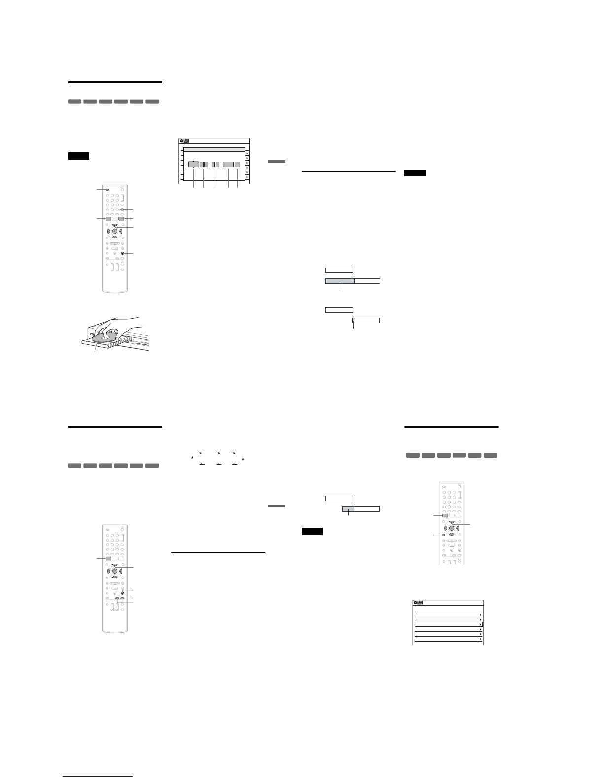
1-12
51
Recording
Timer Recording
You can set the timer for a total of 12 programs, up
to one month in advance.
Note that the maximum continuous recording time
for a single title is 12 hours. Contents beyond this
time will not be recorded.
Follow the steps below to set e ach timer recording
item.
Note
Do not operate your cable box or satellite receiver just
before or during a timer reco rding. This may prevent the
accurate recording of a program.
1
Press Z OPEN/C LOSE, and place a
recordable disc on the disc tray.
2
Press Z OPEN/CLOSE to close the disc
tray.
Wait until “LOAD” disappears from the front
panel display.
Unused discs are automatically formatted. For
the DVD-RW/DVD-R’s recording format
(VR mode or Video mode), see “Formatting a
new disc” on page48.
3
Press TIMER.
4
Select an item using </, and adjust
using M/m.
A “Date”: Sets the date usi ng M.
To record the same program e very day or
the same day every week , press m.
The item changes as follows:
Today y Sun-Sat (Sunday to Saturday)
y Mon-Sat (Monday to Saturday) y
Mon-Fri (Monday to Friday) y Sun
(every Sunday) y Mon (every Monday)
y … y Sat (every Saturday) y
1month later y … y Today
B “Start”: Sets the start time.
C “End”: Sets the stop tim e.
D “Ch”: Selects the channel or input
source.
You can switch the broadcast using the
DIGITAL/ANALOG button.
E “Mode”: Selects the recording mode
(page 47).
To use the Rec Mode Adjust functi on
(page 52), select “AUT O.”
If you make a mistake, select the item and
change the setting.
+
RW
+
R
-
RW
VR
-
RW
Video
-
R
VR
-
R
Video
11 22 33
44 55 66
77 880099
M/m/</,,
ENTER
Z OPEN/
CLOSE
x STOP
SYSTEM
MENU
TIMER
DIGITAL/
ANALOG
DV
I
N
L
(
M
O
N
O
)
A
U
D
I
O
R
V
I
D
E
O
S
V
I
D
E
O
L
I
N
E
-
2
I
N
O
N
E
-
T
O
U
C
H
D
U
B
B
I
N
G
Recording side facing down
01 DVD 04/15 09:00PM 10:00PM CH8
--- --/-- --:-- --:-- ---- ---04
--- --/-- --:-- --:-- ---- ---05
--- --/-- --:-- --:-- ---- ---06
03 --- --/-- --:-- --:-- ---- ---
02 DVD 04/30 09:15PM 09:45PM CH11
10:10 AM
No Rec To Date Start End Source Mode Edit
Timer – Standard
No.01
:
PM PM
:
09 00 10 00 Ch 8 SP
12 3 45
Date Start End Ch Mode
Today
,continued
52
5 Press ENTER.
The Timer List menu (page 54) appea rs.
The c indicator lights up in the front panel
display, and the recorder is ready to start
recording.
•If the c indicator flashes in the front panel
display, a recordable disc is not inserted.
Insert a recordable disc and check that there
is enough disc space for the recording.
•If timer settings overlap, a message appears.
To change or cancel a timer recording, select
“Edit” from the Timer List (page54).
6 Press SYSTEM MENU to turn off the menu.
There is no need to turn off th e recorder before
the timer recording starts.
To stop recording
Press x STOP twice.
Note that it may take a few seconds for the
recorder to stop rec ording.
If timer settings overlap
The program that starts first has priority and the
second program starts recording only after the first
program has finished. If the programs start at the
same time, the program listed first in the menu has
priority. If the end time of one setting and the start
time of another timer setting is the same, the
beginning of the program that star ts later will be
cut.
To change or cancel timer re cording
See “Changing or Canceling Timer Settings
(Timer List)” on page 54.
To use the Rec Mode Adjust function
If the remaining disc space is not enough for the
current recording, the recorder automatically
adjusts the recording mode. Select “AUTO” for
“Mode” when setting the timer.
z Hints
•You can pla y the recorded program by selecting the
program title in the Title List menu.
•You can a lso turn on the timer programming menu
from the System Menu. Press SYSTEM MENU to
select “Timer,” and select “Timer-Standard.”
•You can use the number buttons and the dot (·) button
to select a channel.
•You can se lect a video source from the LINE 1 IN or
LINE 2 IN jacks, using the INPUT button.
Notes
•To record a cable or satellite program, turn on the cable
box or satellite receiver and select the program you
want to record. Leave the cable box or satellite receiver
turned on until the recorder finishes recording.
•Eve n when correctly set, the program may not be
recorded if another recording is underway, or ot her
prioritized timer setting overlaps.
•Before the timer recording starts, “TIMER REC”
flashes in the front panel display.
•The recorder automatically turns off when a timer
recording finishes, even if the recording started with
the recorder turned on.
•The recorder does not record programs with CopyNever signals. Such recordings stop after a few
seconds.
•Digi tal closed captions cannot be recorded (page 35).
•For audio settings, “Stream 1” is usua lly recorded
(page 35).
•When you set the Digital Rating, a program with a
digital rating beyond your limit setting cannot be
recorded correctly (page8 5).
7:00 8:00 9:00 10:00
7:00 8:00 9:00 10:00
Program 1
Program 2
will be cut off
Program 1
Program 2
will be cut off
53
Recording
Recording From Connected
Equipment With a Timer
(Synchro Rec)
You can set the recorder to automatically record
programs from connected equipment that has a
timer function (such as a satellite tuner). Connect
the equipment to the LINE 1 IN jacks on the rear
of the recorder (page 18).
When the connected equipment turns on, the
recorder starts record ing a program from the LIN E
1 IN jacks.
1
Insert a recordable disc.
2
Select the line input audio.
Set “Line Audio Input” of “Audio” setup to
“Stereo” or “Main/Sub” in the “Setup”
display (page 83).
3
Press REC MODE repeatedly to select the
recording mode.
The display changes on the TV screen as
follows:
For details about the recording mode, see
page 47.
4
Set the timer on the connected equipment
to the time you want to record, and turn it
off.
5
Press SYNCHRO REC.
The SYNCHRO REC indicator lights up on
the front panel and the recorder stands by for
Synchro-Rec.
The recorder starts recording when a signal is
received from the connected equipm ent.
When the connected equipment turns off, the
recording stops and the recorder turns off.
To stop recording
Press x STOP twice.
To cancel a Synchro-Rec function
Press SYNCHRO REC before recording starts.
The SYNCHRO REC indicator on the recorder
turns off.
If you press SYNCHRO REC during SynchroRec, the recording stops, the SYNCHRO REC
indicator turns off, and the recorder turns off.
+
RW
+
R
-
RW
VR
-
RW
Video
-
R
VR
-
R
Video
11 22 33
44 55 66
77 880099
M/m/</,,
ENTER
SYNCHRO
REC
x STOP
REC MODE
SYSTEM
MENU
HQ SPHSP LSP
SLP LPEP ESP
,continued
54
If the timer settings of a Synchro-Recording
and another timer recording overlap
Regardless of whether or not the p rogram is a
Synchro-Rec program, the program that starts first
has priority. The recorder star ts recording the
second program about ten seconds after the first
program has finished. If the end time of one
setting and the start time of another timer setting is
the same, the beginning of the program that starts
later will be cut.
Notes
•The recorder starts recording only after detecting the
video signal from the connected e quipment. The
beginning of the program may no t be recorded
regardless of whether or not the recorder’s power is on
or off.
•To use the connected equipment dur ing Synchro-Rec
standby, cancel the standby mode by pressing
SYNCHRO REC. To return to standby mode again, be
sure to turn off the equipment and press SYNC HRO
REC, before Synchro-Rec starts.
•The Synchro-Rec function does not work with some
tuners. For details, see the tuner’s operating
instructions.
•Dur ing Synchro-Rec standby, the Auto Clock Set
function does not work (page 78).
•After a recording has finished, the recorder enters the
Synchro-Rec standby mode until the SYNCHRO REC
indicator turns off.
• If Synchro-R ec starts with the recorder turned on, the
recorder will turn off when the recording ends.
•The recorder does not record programs with CopyNever signals. Such recordings stop after a few
seconds.
Changing or Canceling
Timer Settings (Timer List)
You can change or cancel timer settings using the
Timer List menu.
1 Press SYSTEM MENU.
The System Menu appears.
2 Select “Timer,” and press ENTER.
3 Select “Timer List,” and press ENTER.
Timer information displays the recording
date, time, recording mode, etc.
If there are more than six timer settings, press
m to display the next page.
4 Select the timer setting you want to change
or cancel, and press ENTER.
The sub-menu appears.
7:00 8:00 9:00 10:00
Program 1
Program 2
will be cut off
+
RW
+
R
-
RWVR-RWVideo
-
RVR-RVideo
11 22 33
44 55 66
77 880099
SYSTEM
MENU
M/m/</,,
ENTER
O RETURN
01 04/15 09:00PM 10:00PM Ch 8
--/-- --:-- --:-- ---- ---04
--/-- --:-- --:-- ---- ---05
--/-- --:-- --:-- ---- ---06
03 --/-- --:-- --:-- ---- ---
02 04/30 09:15PM 09:45PM D11.1
10:10 AM
SP
SP
Timer List
No Date Start End Ch Mode Edit
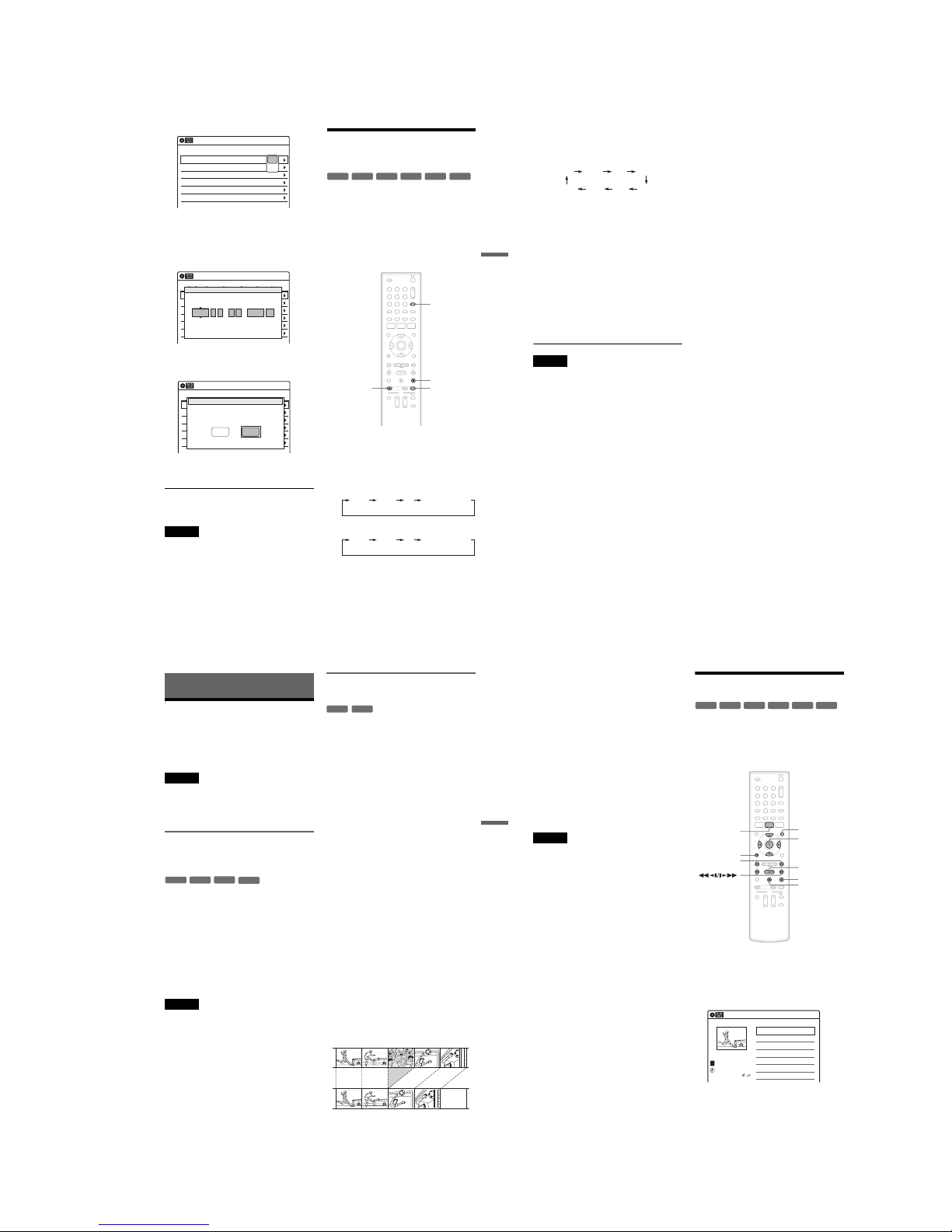
1-13
55
Recording
5 Select one of the options, and press
ENTER.
“Edit”: Changes the timer setting.
Select an item using </, and adjust using
M/m. Press ENTER.
“Erase”: Erases the timer setting.
Select “OK” and press ENTER when a sked
for confirmation.
6 Press SYSTEM MENU to turn off the Timer
List.
To return to the previous display
Press O RETURN.
Notes
•Even when correctly set, the program may not be
recorded if another recording is underway, or other
prioritized timer setting o verlaps. For priority, see
page 52.
•You cannot change the tim er settings for a recording
currently underway.
Recording From Connected
Equipment Without a Timer
You can record from a connected VCR or similar
device. For connection details, see “Connecting a
VCR or Similar Device” on page 32.
Use the DV IN jack on the front panel if the
equipment has a DV/D8 output jack (i.LINK
jack).
To record from a digital video camera connec ted
to the DV IN jack, see page 71.
1 Insert a recordable disc.
2 Press INPUT repeatedly to select an input
source according to the connection you
made.
The front panel display changes as follows:
When selecting a digital channel
When selecting an analog channel
01 04/15 09:00PM 10:00PM Ch 8
--/-- --:-- --:-- ---- ---04
--/-- --:-- --:-- ---- ---05
--/-- --:-- --:-- ---- ---06
03 --/-- --:-- --:-- ---- ---
02 04/30 09:15PM 09:45PM D11.1
10:10 AM
Timer List
No Date Start End Ch Mode Edit
Edit
Erase
01 DVD 04/15 09:00PM 10:00PM CH8
--- --/-- --:-- --:-- ---- ---04
--- --/-- --:-- --:-- ---- ---05
--- --/-- --:-- --:-- ---- ---06
03 --- --/-- --:-- --:-- ---- ---
02 DVD 04/30 09:15PM 09:45PM CH11
10:10 AM
No Rec To Date Start End Source Mode Edit
Timer – Standard
No.01
: PM PM
:
09 00 10 00 Ch 8 SP
Date Start End Ch Mode
04/15
01 DVD 04/15 09:00PM 10:00PM CH8
--- --/-- --:-- --:-- ---- ---04
--- --/-- --:-- --:-- ---- ---05
--- --/-- --:-- --:-- ---- ---06
03 --- --/-- --:-- --:-- ---- ---
02 DVD 04/30 09:15PM 09:45PM CH11
10:10 AM
No Media Date Start End Source Mode Edit
Timer List
Do you want to erase ‘‘No.01’’?
OK
Cancel
+
RW
+
R
-
RW
VR
-
RW
Video
-
R
VR
-
R
Video
11 22 33
44 55 66
77 880099
INPUT
x STOP
REC MODE
z REC
LINE2 DVLINE1 Digital Channel
LINE2 DVLINE1 Analog Channel
,continued
56
3
Press REC MODE repeatedly to select the
recording mode.
The display changes on the TV scre en as
follows:
For details about the recording mo de, see
page 47.
4
Select the line input audio.
Set “Line Audio Input” of “Audio” set up to
“Stereo” or “Main/Sub” in the “Setup”
display (page 83).
5
Insert the source tape into the connected
equipment and set to playbac k pause.
6
Press z REC on this recorder and the
pause or play button on the conne cted
equipment at the sam e time.
Recording starts.
To stop recording, press x STOP on this
recorder.
Notes
•A video game image may not be recorded clearly.
•The recorder does not record programs with CopyNever signals. Such recordings stop after a few
seconds.
•During recording or recording pause, you cannot
change the recording mode.
•You cannot chang e the channel or input source during
recording.
HQ SPHSP LSP
SLP LPEP ESP
57
Editing
Editing
Before Editing
This recorder offers various edit options for
various disc types. Befo re you edit, check the disc
type in the front panel display, and select the
option available for your disc (p age 12).
Notes
•You may lose the edited contents if you remov e the disc
or a timer recording starts while editing.
•You cannot edit recordings on DVD-RWs (Video
mode), DVD+R, or DVD-Rs (Video mode) recorded
on other DVD equipment.
Edit options for DVD+RWs/DVD-RWs
(Video mode)/DVD+Rs/DVD-Rs
(Video mode)
You can perform simple edits. Since Vi deo mode
titles are actual recordings on the disc, you cannot
undo any edits you make. The edit functions
available for Video mode titles are:
–Renaming a title (page 61).
–Erasing a title (page 58).
–Setting protection against erasure (DVD+RWs
only) (page 58).
–Erasing a section of a title (A-B Erase)
(DVD+RWs only) (page 59).
–Dividing a title (DVD+RWs only) (page 60).
Notes
•Once the disc is finalized, you cannot edit or record on
the disc (except for DVD+RWs).
• If a message appears and indicates that the disc’s
control information is ful l, erase unnecessary titles.
Edit options for DVD-RWs (VR mode)/
DVD-Rs (VR mode)
You can enjoy advanced edit functions. First you
have two options for a DVD-RW (VR mode) and
DVD-R (VR mode): editing either the original
recording (called the “original” ), or the playback
information created from the original (called a
“Playlist”). Since each is different in nature and
offers different merits, read the following and
select the one that better suits your needs.
To edit original titles
Edits made to the original titles are final. If you
plan to retain an unaltered original recording,
create and edit a Playlist (see below). The edit
functions available for original titles are:
–Renaming a title (page 61).
–Erasing a title (page 58).
–Erasing a chapter (page 59).
–Setting protection against erasure (page 58).
–Erasing a section of a title (A-B Erase) (page59).
–Dividing a title (page 60).
To create and edit Playlist titles
A Playlist is a group of Playlist titles created from
the original title for editing purposes. W hen you
create a Playlist, only the control information
necessary for playback, such as the playback
order, is stored on the disc. Since the original titles
are left unaltered, Playlist titles can be re-edited.
If you erase an original title used in a Playlist, that
Playlist is also erased.
Example: You have recorded the final few
matches of a soccer tournament on a DVD-RW
(VR mode). You want to create a digest with the
goal scenes and other highlights, but you also want
to keep the original recording.
-
RWVideo
+
RW
+
R
-
RVideo
-
RWVR-RVR
,continued
58
In this case, you can compile highlight scenes as a
Playlist title. You can even rearrange the scene
order within the Playlist title. See “Editing a
Playlist” on page 64.
The advanced edit functions a vailable for Playlist
titles are:
–Renaming a title (page 61).
–Erasing a title (page 58) .
–Erasing a chapter (page 59).
–Erasing a section of a title (A-B Erase) (pa ge 59).
–Editing a Playlist scene (page 64).
–Dividing a title (page 60).
–Combining titles (page 65).
z Hint
You can switch the Title List to show original or Pl aylist.
While the Title List menu is turned on, press ORIGINAL/
PLAYLIST repeatedly.
Notes
•You cannot protect Playlist titles.
• If a messa ge appears and indicates that the disc’s
control information is full, erase un necessary titles.
•You cannot create or edit Playlist titles on a finalized
disc. When you want to edit or record on the DVD-RW
(VR mode) again, unfinalize the disc (page 69).
Editing a Title
This section explains the basic edit functions. Note
that editing is irreversible. To edit a DVD-RW
(VR mode) or DVD-R (VR mode) without
changing the original recordings, create a Playlist
title (page 62).
1
Press TITLE LIST.
When editing a DVD-RW (VR mode) or
DVD-R (VR mode), press ORIGINAL/
PLAYLIST to switch to the “Title List
(Original),” if necessary.
2
Select a title, and press ENTER.
The sub-menu appears.
-
RW
VR
-
RW
Video
+
RW
+
R
-
R
Video
-
R
VR
11 22 33
44 55 66
77 880099
M/m/</,,
ENTER
TITLE LIST
H PLAY
x STOP
X PAUSE
ORIGINAL/
PLAYLIST
./>
O RETURN
Title List (Original)
10:10 AM
>
>
T
No. Title Length Edit
01 01:29:03
02 00:31:23
03 >01:59:00
04 >00:58:56
1/4
D11.1
D22.2
Ch 23
Ch 66
D11.1
May/02/2007
08:00 PM
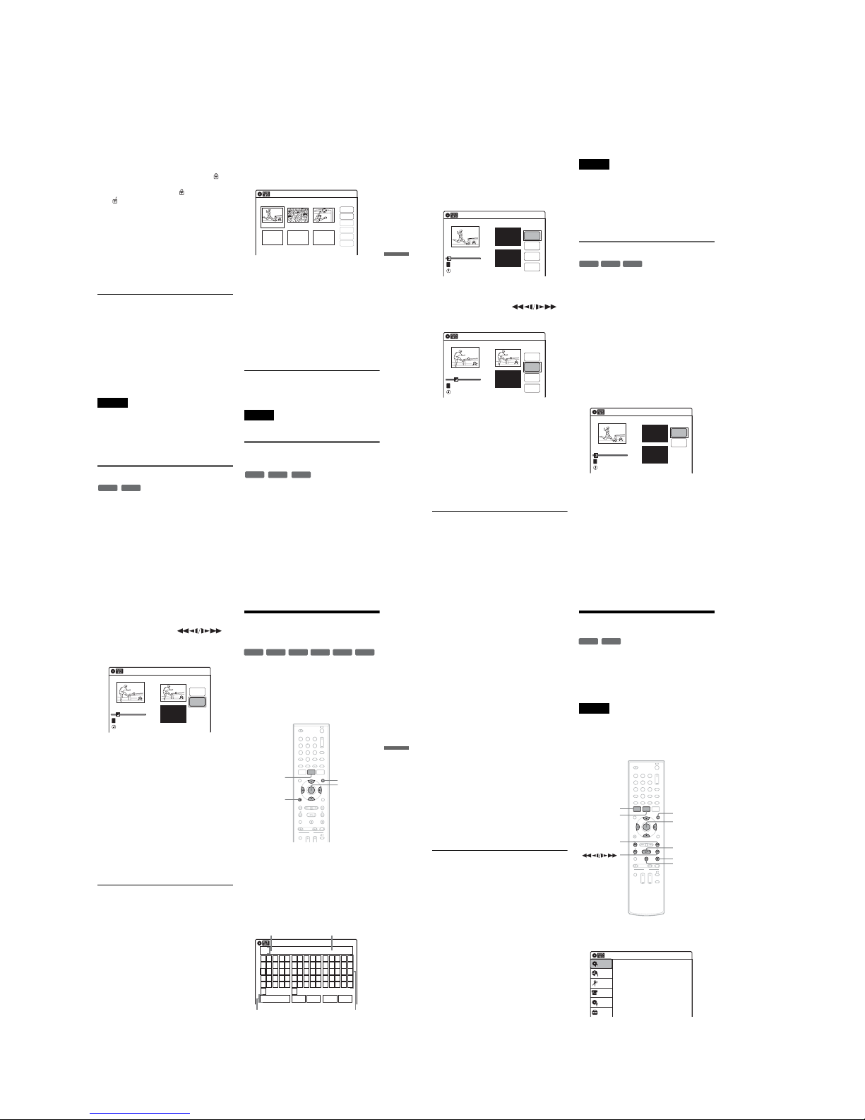
1-14
59
Editing
3
Select an option, and press ENTER.
You can select from the following:
“Title Erase”: Erases the selected title. Select
“OK” when asked for confirmation.
“Chapter Erase”
*1
: Allows you to select a
chapter in the title and erase it (see below).
“Protect”
*2
: Protects the title. Select “On”
when the Protection display appears. “ ”
appears for the protected title. To ca ncel the
protection, select “Off.” “ ” changes to
“.”
“Title Name”: Allows you to rename the title
(page 61).
“A-B Erase”
*2
: Erases a section of the title
(see below).
“Divide Title”
*2
: Divides a title into two
(page 60).
*1
DVD-RWs (VR mode) and DVD-Rs (VR mode)
only
*2
DVD+RWs, DVD-RWs (VR mode), and DVD-R
(VR mode) only
About freeing up disc space
Erasing titles, chapters, or scenes:
–frees up disc space on a DVD-RW (VR mode).
–frees up disc space on a DVD+RW/DVD-RW
(Video mode) only when you erase the last title
or chapter.
–cannot free up disc space on a DVD+R/DVD+R
DL/DVD-R.
z Hint
You can also rename a disc (page 68).
Notes
•When editing a DVD-RW (Video mode), DVD+R, or
DVD-R, finish all editing before finalizing the disc.
You cannot edit a finalized disc.
•You cannot erase protected t itles or erase chapters from
a protected title.
• If you erase an original title used in a Playlist, that
Playlist is also erased.
Erasing a chapter (Chapter Erase)
You can select a chapter within a title and erase it.
Note that erasing chapters from original titles
cannot be undone.
1
Press TITLE LIST.
Press ORIGINAL/PLAYLIST to switch to the
“Title List (Original),” if necessary.
2
Select a title, and press ENTER.
The sub-menu appears.
3
Select “Chapter Erase,” and press EN TER.
The display for erasing chapters appears.
4
Select the chapter you want to era se, and
press ENTER.
“Check” is selected. To preview the chapter,
press ENTER. When playback finishes or
when you press O RETURN, the display
returns to “Chapter Erase (Original).”
5
Select “Erase,” and press ENTER.
The display asks for co nfirmation.
6
Select “OK,” and press ENTER.
The selected chapter is erased from the title.
To erase other chapters, repeat from step 4.
z Hint
You can also erase chapters from a Playlist title
(page 64).
Note
If you erase an original title used in a Playlist, tha t Playlist
is also erased.
Erasing a section of a title
(A-B Erase)
You can select a section (scene) within a title and
erase it. Note that erasing scenes from ori ginal
titles cannot be undone.
-
RW
VR
-
R
VR
Chapter Erase (Original)
10:10 AM
Chapter No. 1 / 3 Title No.01
03 00:04:2002 00:00:1001 00:00:34
Check
Erase
Modify
Move
Add
Copy
-
RW
VR
-
R
VR
+
RW
,continued
60
1 Press TITLE LIST.
When editing a DVD-RW (VR mode) or
DVD-R (VR mode), press ORIGINAL/
PLAYLIST to switch to the “Title List
(Original),” if necessary.
2 Select a title, and press ENTER.
The sub-menu appears.
3 Select “A-B Erase,” and press ENTER.
The display for setting point A and B appears.
“Start” is selected.
4 Press ENTER at the start point of the
section to be erased (point A).
You can use H PL AY, ,
./>, x STOP, and X PAUSE to find
the point. “End” is selected.
5 Press ENTER at the end point of the section
(point B).
“Erase” is selected.
To reset the start or end point, select “Start” or
“End” and repeat from step 4 or 5 .
6 Press ENTER.
The display asks for confirma tion.
7 Select “OK,” and press ENTER.
The scene is erased.
To continue, repeat from step 4.
To finish, select “Finish,” and press ENTER.
z Hints
•A chapter mark is inserted after the scene was erased.
The chapter mark divides the title into sep arate chapters
on either side of the mark.
•You can also erase a section of a Playlist title (page 64).
Notes
•Images or sound m ay be momentarily interrupted at the
point where you erase a section of a title.
•Sections sho rter than five seconds may not be erased.
•The start and end points of a title may be different from
what you have set.
•The total playing time of the title does not change even
if a scene was erased.
•If you er ase an original title used in a Playlis t, that
Playlist is also erased.
Dividing a title into two (Divide Title)
You can divide a title into two. Note that dividing
original titles cannot be undone.
1 Press TITLE LIST.
When editing a DVD-RW (VR mode) or
DVD-R (VR mode), press ORIGINAL/
PLAYLIST to switch to the “Title List
(Original),” if necessary.
2 Select a title, and press ENTER.
The sub-menu appears.
3 Select “Divide Title,” and press ENTER.
The display for setting the dividing point
appears.
“Point” is selected.
A-B Erase
10:10 AM
Title No.01
End 00:00:00
Start 00:00:00
Start
End
Erase
Finish
00:00:07
T
Title No.01
May/02/2007 08:00 PM
A-B Erase
10:10 AM
Title No.01
End 00:00:00
Start 00:00:10
Start
End
Erase
Finish
00:00:10
T
Title No.01
May/02/2007 08:00 PM
-
RW
VR
+
RW
-
R
VR
Divide Title (Original)
10:10 AM
Title No.01
T
Point
Divide
00:00:07
Title No. 01
Start 00:00:00
End 00:00:00
May/02/2007 08:00 PM
61
Editing
4
Press ENTER at the point whe re you want to
divide the title.
You can use H PL AY, ,
./>, x STOP, and X PAUSE to find
the point.
“Divide” is selected.
5
Press ENTER.
The display asks for confirmation.
To reset the dividing point, select “N o” and
press ENTER, then repeat from step 4.
6
Select “Yes,” and press ENTER.
The display asks whether to rename the title.
To use the same name as before, select “No”
and press ENTER to finish.
7
Select “Yes,” and press ENTER.
The “Title Name” display appea rs.
8
Follow steps 4 to 6 of “Changing the Name
of a Title” (page 61) to complete
renaming.
The divided title appears in the Title List with
the new name.
z Hints
•You can also divide a Playlist title (page 64).
• If the divi ding point is set too close to the beginning of
the title, the title cannot be divided.
Changing the Name of a
Title
You can enter a title name of up to 32 characters.
Since the displayed number of charac ters is
limited, their appearance in menus such as Title
List may be different. When the display for
entering characters appears, follow the steps
below.
1
Press TITLE LIST.
When editing a DVD-RW (VR mode) or
DVD-R (VR mode), press ORIGINAL/
PLAYLIST to switch to the “Title List
(Original),” if necessary.
2
Select a title, and press ENTER.
The sub-menu appears.
3
Select “Title Name,” and press ENTER.
The “Title Name” display appears.
10:10 AM
Title No.01
T
00:00:10
Divide Title (Original)
Title No. 01
End 00:00:10
Start 00:00:00
Point
Divide
May/02/2007 08:00 PM
+
R
-
RW
VR
-
RW
Video
+
RW
-
R
VR
-
R
Video
11 22 33
44 55 66
77 880099
M/m/</,,
ENTER
O RETURN
TITLE LIST
ORIGINAL/
PLAYLIST
Title Name
K
_
A B C D E
F G H I J
K L M N O
P Q R S T
U V W X Y
Z
a b c d e
f g h i j
k l m n o
p q r s t
u v w x y
z
1 2 3 4 5
6 7 8 9 0
- _ + = .
~
!
@ # $
%^& ( )
Backspace Space Delete Clear Finish
10:10 AM
Input row
Character paletteSetting buttons
Cursor
,continued
62
4 Select the character you want to enter
using M/m/</,, and press ENTER.
The selected character appear s in the input
row.
You can only enter charact ers and symbols
that are displayed.
•To change the cursor position, select the
input row using M, and press </,.
•To erase a character, select ei ther of the
following setting buttons and press ENTER.
“Backspace”: Erases the character t o the left
of the cursor.
“Delete”: Erases the character at the cursor
position.
“Clear”: Erases all the characters in the input
row.
•To insert a space, move th e cursor to the
desired position, select “Space,” and press
ENTER.
•To insert a character, mo ve the cursor to the
desired position, select the character, and
press ENTER.
5 Repeat step 4 to enter the remaining
characters.
To return to the Title List without renaming
the title, press O RETURN.
6 Select “Finish,” and press ENTER.
z Hint
You can also rename a disc (page 68). Follow steps 4 to
6 above when the “Disc Name” display appears.
Creating a Playlist
Playlist titles allow you to edit without changing
the original recordings (see “Edit options for
DVD-RWs (VR mode)/DVD-Rs (VR mode)” on
page 57). You can create a Playlist title by
combining up to 99 sections (scenes) from original
titles.
Notes
•If you er ase an original title used in a Playlis t, that
Playlist is also erased.
•You cannot cre ate or edit Playlist titles on a finalized
disc. When you want to edit or record on the DVD-RW
(VR mode) again, unfinalize the disc (page 69).
1 Press SYSTEM MENU while the r ecorder is
in stop mode.
-
RWVR-RVR
11 22 33
44 55 66
77 880099
M/m/</,,
ENTER
SYSTEM
MENU
H PLAY
TITLE LIST
x STOP
X PAUSE
ORIGINAL/
PLAYLIST
./>
Press ENTER :
Title Menu for DVD Title List.
10:10 AM
Title List (Original)
Setup
Disc Setting
Edit
Title List
Timer
DV/D8 Dubbing
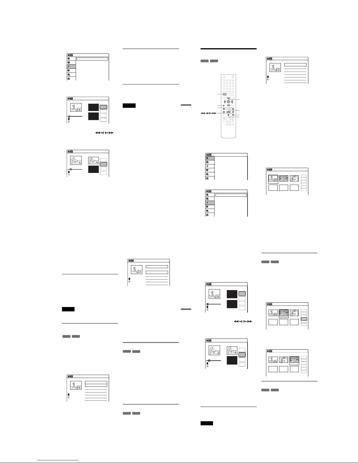
1-15
63
Editing
2 Select “Edit,” and press ENTER.
3 Select “Create Playlist,” and press ENTER.
The display for creating a Playlist appears.
“Start” is selected.
4 Press ENTER at the start point.
You can use H PL AY, ,
./> and X PAUSE to find the point. At
the point you want to select, press H PLAY
or X PAUSE, and press ENTER.
“End” is selected.
5 Press ENTER at the end point.
“Make” is selected.
To reset the start or end point, select “Start” or
“End” and repeat step 4 or 5.
6 Press ENTER.
The selected section is captured as a scene. To
continue, repeat from step 4.
7 When you finish capturing scenes, selec t
“Finish” and press ENTER.
Playing a Playlist title
1 Press TITLE LIST.
2 Press ORIGINAL/PLAYLIST to switch to the
“Playlist” Title List.
3 Select a Playlist title, and press ENTER.
The sub-menu appears.
4 Select “Play,” and press ENTER.
z Hint
When a Playlist title is created, th e start and end points
will become chapter marks, and each scene will become
a chapter.
Notes
•The picture may pause when an edited scene is played.
•The start and end points in a title may be different fro m
what you have set.
10:10 AM
Create Playlist
Edit Playlist
Edit
Setup
Disc Setting
Edit
Title List
Timer
DV/D8 Dubbing
Create Playlist
10:10 AM
Scene No.01
End 00:00:00
Start 00:00:00
T
Start
End
Make
Finish
00:00:07
---/--/---- --:--
Playlist No. 01
10:10 AM
Scene No.01
T
Finish
00:00:10
Create Playlist
Playlist No. 01
End 00:00:00
Start 00:00:10
Start
End
Make
---/--/---- --:--
64
Editing a Playlist
You can edit Playlist titles or scenes within them,
without changing the actual re cordings.
1
Press SYSTEM MENU while the recorder is
in stop mode.
2
Select “Edit,” and press ENTER.
3
Select “Edit Playlist,” and pr ess ENTER.
The “Playlist” Title List appears.
4
Select a Playlist title, and press ENTER.
The sub-menu appears.
5
Select an option, and press ENTER.
Select from the following options. For details,
see the pages in parentheses.
“Title Erase”: Erases the title. Select “OK”
when asked for confirmation.
“Chapter Erase”: Allows you to select
chapters in the Playlist title to erase (page 59).
“Title Name”: Allows you to rename the title
(page 61).
“A-B Erase”: Allows you to select sections in
the title to erase (page 59).
“Edit Scene”: Allows you to re-edit scenes in
the Playlist title. Go to step 6.
“Divide Title”: Divides the title in two at a
desired point (page 60).
“Combine Titles”: Allows you to combine
two titles into one (page 65).
6
Select “Edit Scene,” and press ENTER.
The display for editing scenes appears.
“Check”: Allows you to preview a scen e.
Starts playback of the selected scene when
you press ENTER. The display returns to the
“Edit Scene” display when the playback
finishes or when you press O RETURN.
“Erase”: Erases a scene (page 65).
“Modify”: Allows you to change the start and
end point of a scene (page 65).
-
RW
VR
-
R
VR
11 22 33
44 55 66
77 880099
SYSTEM
MENU
M/m/</,,
ENTER
H PLAY
x STOP
X PAUSE
O RETURN
./>
Press ENTER :
Title Menu for DVD Title List.
10:10 AM
Title List (Original)
Setup
Disc Setting
Edit
Title List
Timer
DV/D8 Dubbing
10:10 AM
Create Playlist
Edit Playlist
Edit
Setup
Disc Setting
Edit
Title List
Timer
DV/D8 Dubbing
Playlist
10:10 AM
01 >00:05:04
02 >00:00:51
T
No. Title Length Edit1/2
D11.1
Ch 96
D11.1
May/02/2007
03:25 PM
Edit Scene
10:10 AM
Scene No.01 / 03 Playlist No.01
03 00:04:2002 00:00:1001 00:00:34
Check
Erase
Modify
Move
Add
Copy
65
Editing
“Move”: Allows you to change scene or der
(page 66).
“Add”: Allows you to add other sc enes before
a selected scene (page66).
“Copy”: Allows you to copy a scene
(page 67).
To return to the previous display
Press O RETURN.
To turn off the display
Press SYSTEM MENU.
z Hint
The Resume Play function will work for scene playback.
Note
You cannot create or edit Playlist titles on a finalized
disc. When you want to edit or record on the DVD-RW
(VR mode) again, unfinalize the disc (page 69).
Combining two titles into one
(Combine Titles)
You can select a Playlist title and combine it with
another Playlist title.
1 Follow steps 1 to 4 of “Editing a Playlist”
(page 64) to select a Playlist title.
The sub-menu appears.
2 Select “Combine Titles,” and press
ENTER.
The next title below is also selected.
3 Select a Playlist title to be combined.
4 Press ENTER.
The display asks for confirmation .
5 Select “Yes,” and press ENTER.
The display asks whether to rename the title.
To use the same name as before, sele ct “No”
and press ENTER to finish.
6 Select “Yes,” and press ENTER.
The “Title Name” display appears.
7 Follow steps 4 to 6 of “Changing the Name
of a Title” (page 61) to complete
renaming.
The two Playlist titles become one Playlist
title with the new name.
Erasing a scene (Erase)
You can erase a selected scene.
1 Follow steps 1 to 6 of “Editing a Playlist”
(page 64).
The “Edit Scene” display appears.
2 Select the scene you want to erase, and
press ENTER.
3 Select “Erase,” and press ENTER.
The display asks for confirmation .
4 Select “OK,” and press ENTER.
The selected scene is erased.
To erase other scenes, repeat from step 2.
Modifying a scene (Modify)
You can change the start and end point of the
selected scene.
-
RWVR
-
RVR
Playlist
10:10 AM
>
>
T
No. Title Length Edit
01 00:05:04
02 00:00:51
03 >01:59:00
04 >00:58:56
1/4
D11.1
D22.2
Ch 23
Ch 66
D11.1
May/02/2007
03:25 PM
Playlist
10:10 AM
>
>
T
No. Title Length Edit
01 00:05:04
02 00:00:51
03 >01:59:00
04 >00:58:56
3/4
D11.1
D22.2
Ch 23
Ch 66
D11.1
May/15/2007
11:30 PM
-
RWVR
-
RVR
-
RWVR
-
RVR
,continued
66
1
Follow steps 1 to 6 of “Editing a Playlist”
(page 64).
The “Edit Scene” display appears .
2
Select the scene you want to modify, and
press ENTER.
3
Select “Modify,” and press ENTER.
“Start” is selected.
4
Press ENTER at the start point.
You can use H PL AY, ,
./> and X PAUSE to find the point. At
the point you want to select, press H PLAY
or X PAUSE, an d press ENTER.
“End” is selected.
5
Press ENTER at the end point.
“Change” is selected.
To reset the start or end point, select “Start” or
“End” and repeat step 4 or 5.
6
Press ENTER.
The display returns to the “Edit Scen e”
display.
The re-selected section is cap tured as a scene.
To modify other scenes, repeat fro m step 2.
To cancel modifying
Select “Cancel,” and press ENTER.
Note
The start and end point of a scene may be d ifferent from
what you have set.
Moving a scene (Move)
You can change the scene order within the Playlist
title.
1
Follow steps 1 to 6 of “Editing a Playlist”
(page 64).
The “Edit Scene” display appears.
2
Select the scene you want to move, and
press ENTER.
3
Select “Move,” and press ENTER.
4
Select a new location using </,, and
press ENTER.
The selected scene moves to the new location.
To move other scenes, repeat from step 2.
Adding a scene (Add)
You can add a scene before the selecte d scene.
1
Follow steps 1 to 6 of “Editing a Playlist”
(page 64).
The “Edit Scene” display appears.
2
Select the location where you want to add,
and press ENTER.
A new scene will be added before the selected
scene.
Modify
10:10 AM
T
Change
Cancel
00:00:07
Playlist No. 01
Scene No.01
End 00:00:00
Start 00:00:00
Start
End
May/02/2007 03:25 PM
Modify
10:10 AM
Scene No.01
T
00:00:10
May/02/2007 03:25 PM
Playlist No. 01
Change
Cancel
End 00:00:00
Start 00:00:10
Start
End
-
RW
VR
-
R
VR
Edit Scene
10:10 AM
Scene No. 02 / 03
03 00:04:2002 00:00:1001 00:00:34
Playlist No.01
Check
Erase
Modify
Move
Add
Copy
Edit Scene
10:10 AM
Scene No. 03 / 03
02 00:04:20 03 00:00:1001 00:00:34
Playlist No.01
Check
Erase
Modify
Move
Add
Copy
-
RW
VR
-
R
VR
 Loading...