

Sony RMT-D163A Service Manual

SERVICE MANUAL
US Model
Canadian Model
PORTABLE CD/DVD PLAYER
DVP-FX705
RMT-D163A
SPECIFICATIONS
DVD Player
Power supply:
DC 9.8V (AC adaptor/ Car Battery Adaptor terminal),
DC 7.6V (Battery)
Power consumption: 13W
(DVD VIDEO Playback with the LCD screen turned on.)
Weight: 1.536 lbs (697g) (without battery pack)
External dimensions (W x H x D):
7.48 x 6.1 x 1.3 inches (190 x 155 x 32.8 mm)
Signal system: NTSC
Laser:
DVD Laser wavelength 662+25 / 662-15 nm
CD Laser wavelength 785+25 / 785-15 nm
Frequency range (audio):
DVD linear sound: 48kHz sampling 8 Hz to 20 kHz
96kHz sampling 8 Hz to 44 kHz
Signal-to-noise ratio (audio): More than 95 dB
Dynamic range (audio): More than 95 dB
Harmonic distortion (audio): 0.008 %
Operating conditions:
Te mperature: 41°F to 95°F, Operation status: Horizontal
Connectors
Video output (VIDEO Out):
1.0 V (p-p), 75 Ω, negative sync., ø3.5mm mini jack x 1
Audio output (AUDIO Out, analog audio):
2.0 Vrms(1 KHz, 0 dB), ø3.5mm mini jack x 1
Earphone terminal: ø3.5mm stereo mini jack x 2
Liquid Crystal Display
Panel size: 7 inches wide (diagonal)
Projection system: R.G.B
Driving system: TFT active matrix
Resolution: 480 x 234
(effective pixel rate: more than 99.99%)
Supplied Accessories
• RCA Audio/Video cable . . . . . . . . . . . . . . . . . . . . . .1
•AC Adaptor (AC-FX105) . . . . . . . . . . . . . . . . . . . . . .1
• AC Power Cord . . . . . . . . . . . . . . . . . . . . . . . . . . . .1
•Car Battery Adaptor (DCC-FX105) . . . . . . . . . . . . . .1
•Battery Pack (NP-FX105) . . . . . . . . . . . . . . . . . . . . .1
•Remote control (RMT-D163A) . . . . . . . . . . . . . . . . .1
• Battery for Remote control (Size : AA(R6)) . . . . . . . .1
•
Design and specifications are subject to change
without notice.
– 2 –
WARNING!!
WHEN SERVICING, DO NO T APPR O A CH THE LASER
EXIT WITH THE EYE TOO CLOSELY. IN CASE IT IS
NECESSARY TO CONFIRM LASER BEAM EMISSION,
BE SURE TO OBSERVE FROM A DISTANCE OF
MORE THAN 25 cm FROM THE SURFACE OF THE
OBJECTIVE LENS ON THE OPTICAL PICK-UP BLOCK.
CAUTION
Use of controls or adjustments or performance of procedures
other than those specified herein may result in hazardous radiation exposure.
SAFETY-RELATED COMPONENT WARNING!!
COMPONENTS IDENTIFIED BY MARK 0 OR DO TTED LINE
WITH MARK 0 ON THE SCHEMATIC DIAGRAMS AND IN
THE PARTS LIST ARE CRITICAL TO SAFE OPERATION.
REPLACE THESE COMPONENTS WITH SONY PARTS WHOSE
PART NUMBERS APPEAR AS SHOWN IN THIS MANUAL
OR IN SUPPLEMENTS PUBLISHED BY SONY.
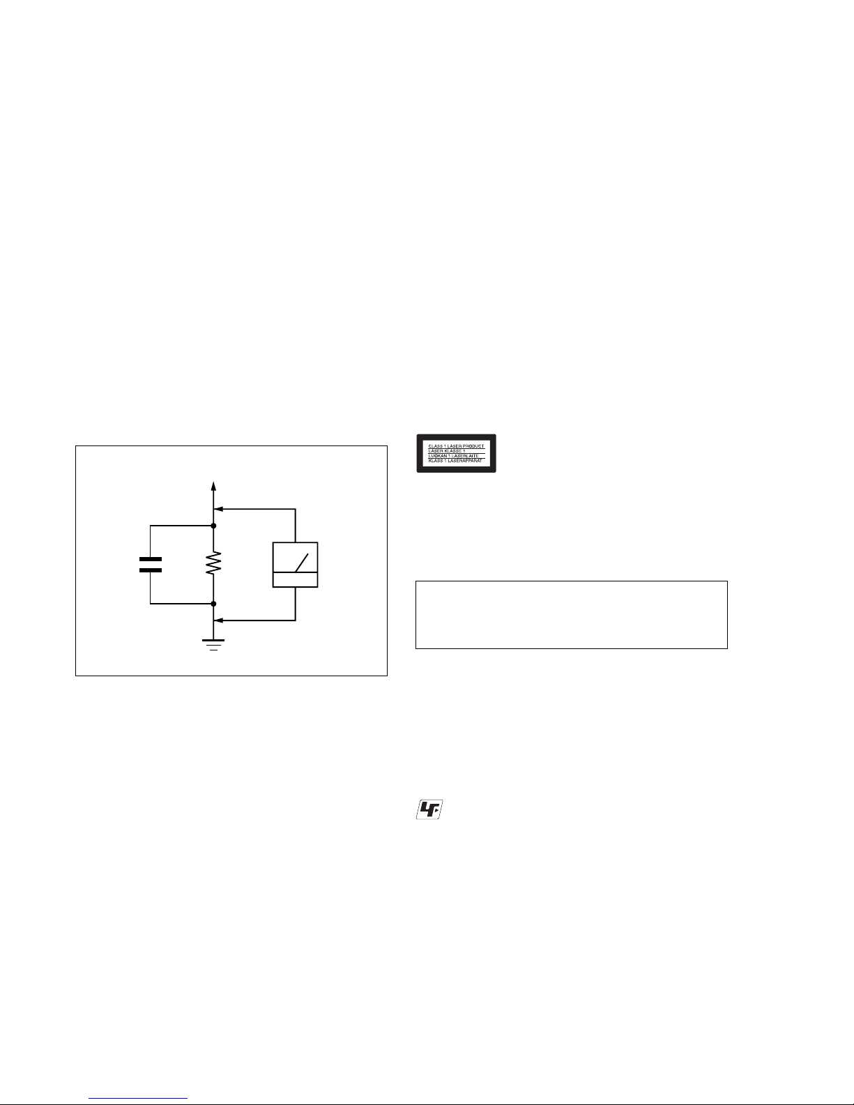
Fig. A. Using an AC voltmeter to check AC leakage.
1.5 k
Ω
0.15 µF
AC
voltmeter
(0.75 V)
To Exposed Metal
Parts on Set
Earth Ground
LEAKAGE TEST
The AC leakage from any exposed metal part to earth ground
and from all exposed metal parts to any exposed metal part having
a return to chassis, must not exceed 0.5 mA (500 microamperes).
Leakage current can be measured by any one of three methods.
1. A commercial leakage tester , such as the Simpson 229 or RCA
WT -540A. Follow the manufacturers' instructions to use these
instruments.
2. A battery-operated AC milliammeter . The Data Precision 245
digital multimeter is suitable for this job.
3. Measuring the voltage drop across a resistor by means of a
VOM or battery-operated AC voltmeter. The “limit” indica-
tion is 0.75V, so analog meters must have an accurate low-
voltage scale. The Simpson 250 and Sanwa SH-63T rd are ex-
amples of a passive VOM that is suitable. Nearly all battery
operated digital multimeters that have a 2V A C range are suit-
able. (See Fig. A)
1. Check the area of your repair for unsoldered or poorly-soldered connections. Check the entire board surface for solder
splashes and bridges.
2. Check the interboard wiring to ensure that no wires are
“pinched” or contact high-wattage resistors.
3. Look for unauthorized replacement parts, particularly transistors, that were installed during a previous repair. Point them
out to the customer and recommend their replacement.
4. Look for parts which, though functioning, show obvious signs
of deterioration. Point them out to the customer and recommend their replacement.
5. Check the line cord for cracks and abrasion. Recommend the
replacement of any such line cord to the customer.
6. Check the B+ voltage to see it is at the values specified.
7. Check the antenna terminals, metal trim, “metallized” knobs,
screws, and all other exposed metal parts for AC leakage.
Check leakage as described below.
SAFETY CHECK-OUT
After correcting the original service problem, perform the following
safety checks before releasing the set to the customer:
CAUTION:
The use of optical instrument with this product will increase eye
hazard.
This CD/DVD player is CLASS 1 LASER PRODUCT.
Unleaded solder
Boards requiring use of unleaded solder are printed with the leadfree mark (LF) indicating the solder contains no lead.
(Caution: Some printed circuit boards may not come printed with
the lead free mark due to their particular size.)
: LEAD FREE MARK
Unleaded solder has the following characteristics.
• Unleaded solder melts at a temperature about 40°C higher than
ordinary solder.
Ordinary soldering irons can be used but the iron tip has to be
applied to the solder joint for a slightly longer time.
Soldering irons using a temperature regulator should be set to
about 350°C.
Caution: The printed pattern (copper foil) may peel away if the
heated tip is applied for too long, so be careful!
• Strong viscosity
Unleaded solder is more viscous (sticky , less prone to flow) than
ordinary solder so use caution not to let solder bridges occur
such as on IC pins, etc.
• Usable with ordinary solder
It is best to use only unleaded solder but unleaded solder may
also be added to ordinary solder.
ATTENTION AU COMPOSANT AYANT RAPPORT
À LA SÉCURITÉ!
LES COMPOSANTS IDENTIFIÉS P AR UNE MARQ UE 0 SUR
LES DIAGRAMMES SCHÉMATIQUES ET LA LISTE DES
PIÈCES SONT CRITIQUES POUR LA SÉCURITÉ DE
FONCTIONNEMENT. NE REMPLACER CES COM- POSANTS
QUE PAR DES PIÈCES SONY DONT LES NUMÉROS SONT
DONNÉS DANS CE MANUEL OU DANS LES SUPPLÉMENTS
PUBLIÉS PAR SONY.

– 3 –
TABLE OF CONTENTS
Section Title Page Section Title Page
1. GENERAL
Precautions ................................................................... 1-1
About This Manual ........................................................ 1-4
This Player Can Play the Following Discs .................... 1-4
Note on playback operations of DVDs .......................... 1-5
Copyrights ..................................................................... 1-5
Notes about the Discs ................................................... 1-5
Identification of Controls ............................................... 1-6
Power Connections ....................................................... 1-8
Playing a Disc................................................................ 1-10
On-Screen Display ........................................................ 1-12
General Features .......................................................... 1-13
Playing an Audio CD or MP3 Disc ................................ 1-15
Programmed Playback.................................................. 1-16
Random Play ................................................................. 1-17
Viewing a JPEG Disc .................................................... 1-18
Initial Settings ................................................................ 1-19
Setting up the Player..................................................... 1-22
To use the player with car battery adaptor ................... 1-23
Troubleshooting ............................................................. 1-24
Language Code List ...................................................... 1-24
Country Code List ......................................................... 1-25
2. DISASSEMBLY
2-1. Cabinet Assy Removal .................................................. 2-1
2-2. CD Lid, MD, Main Board Removal ................................ 2-2
2-3. LCD Panel Removal...................................................... 2-3
3. BLOCK DIAGRAMS
3-1. Oveall Block Diagram.................................................... 3-1
3-2. Power Block................................................................... 3-3
3-3. Audio/Video Block ......................................................... 3-5
3-4. TFT LCD Block.............................................................. 3-7
4. SCHEMATIC DIAGRAMS
4-1. Frame (1/2).................................................................... 4-1
Frame (2/2) .................................................................... 4-3
4-2. Main Power.................................................................... 4-5
4-3. Servo ............................................................................. 4-7
4-4. Mpeg (MTK1389) .......................................................... 4-9
4-5. Audio.............................................................................. 4-11
4-6. Video.............................................................................. 4-13
4-7. Front Micom................................................................... 4-15
4-8. LCD Power .................................................................... 4-17
4-9. Battery Charge .............................................................. 4-19
4-10. Menu Key....................................................................... 4-21
4-11. TFT-LCD Power............................................................. 4-23
4-12. TFT -LCD T100............................................................... 4-25
5. PRINTED WIRING BOARDS
5-1. Circuit Boards Location ................................................. 5-1
5-2. MAIN Board ................................................................... 5-3
5-3. KEY Board..................................................................... 5-7
5-4. TFT-LCD Board ............................................................. 5-9
6. WAVEFORMS
6-1. Details and Waveforms on System Test
and Debugging .............................................................. 6-1
6-2. Circut Voltage Chart ...................................................... 6-9
7. IC PIN FUNCTION DESCRIPTION
7-1. MPEG/DSP/RF Pin Function
(MAIN Board IC501: MT1389) ...................................... 7-1
7-2. FRONT MICOM Pin Function
(MAIN Board IC701: HMS81C1816B) .......................... 7-7
8. ELECTRICAL ADJUSTMENT
8-1. TFT LCD Adjustment .................................................... 8-1
1. Power Measuring........................................................... 8-1
2. VCOM Wav ef orm Adjustment ....................................... 8-1
3. TFT Panel Check........................................................... 8-1
8-2. Standard Video Level .................................................... 8-2
1. Checking Video Output Level ........................................ 8-2
2. Checking S Video Output S-Y....................................... 8-2
3. Checking S Video Output S-C....................................... 8-2
8-3. Adjustment and Checking Location .............................. 8-3
9. TROUBLESHOOTING
9-1. Electrical Troub le Shooting Guide................................. 9-1
1. Power (DC-DC Converter) Circuit ................................. 9-1
2. MPEG Circuit................................................................. 9-4
3. Front Circuit (Dogotrpm & Key)..................................... 9-5
4. RF/Servo Circuit ............................................................ 9-6
9-2. LCD T rouble Shooting Guide (1/2) ................................ 9-10
9-3. LCD T rouble Shooting Guide (2/2) ................................ 9-11
10. REPAIR PARTS LIST
10-1. Exploded Views ............................................................. 10-1
10-1-1. LCD Panel Section................................................... 10-1
10-1-2. Upper Case Section................................................. 10-2
10-1-3. Bottom Case Section ............................................... 10-3
10-2. Electrical Parts List ....................................................... 10-4

– 4 –
MEMO
1-1
SECTION 1
GENERAL
This section is extracted from instruction manual (2-649-081-11).
DVP-FX705
Precautions
4
For Customers in the U.S.A
Owner’s Record
The model and serial numbers are located on the bottom of the unit. Record the serial number in the space provided
below. Refer to them whenever you call upon your Sony dealer regarding this product.
Model No. DVP-FX705
Serial No.______________
For Customers in Canada
If this product is not working properly, please call 1-877-602-2008 for Peace of Mind Warranty Replacement service. For other
product related questions please contact our Customer Information Service Centre at 1-877-899-7669 or write to us at:
Customer Information Service 115 Gordon Baker Road, Toronto, Ontario, M2H 3R6
CAUTION
You are cautioned that any changes or modifications not expressly approved in this manual could void your authority to
operate this equipment.
NOTE
This equipment has been tested and found to comply with the limits for a Class B digital device, pursuant to Part 15 of the
FCC Rules. These limits are designed to provide reasonable protection against harmful interference in a residential installation. This equipment generates, uses, and can radiate radio frequency energy and, if not installed and used in accordance
with the instructions, may cause harmful interference to radio communications. However, there is no guarantee that interference will not occur in a particular installation. If this equipment does cause harmful interference to radio or television reception, which can be determined by turning the equipment off and on, the user is encouraged to try to correct the interference
by one or more of the following measures:
– Reorient or relocate the receiving antenna.
– Increase the separation between the equipment and receiver.
– Connect the equipment into an outlet on a circuit different from that to which the receiver is connected.
– Consult the dealer or an experienced radio/TV technician for help.
Introductions
5
Precautions (continued)
• The power requirements and power consumption of this
unit are indicated on the AC adaptor. Check that the unit’s
operating voltage is identical with your local power supply.
On safety
• Caution – The use of optical instruments with this product
will increase eye hazard.
• To prevent fire or shock hazard, do not place objects filled
with liquids, such as vases, on the apparatus.
• Should any solid object or liquid fall into the cabinet,
unplug the player and have it checked by qualified personnel before operating it any further.
• Do not put any foreign objects in the DC IN 9.8V (external
power input) jack.
• This car adaptor is not intended to be serviced.
Should the product cease to function in its intended
manner, it should be returned to the manufacturer or to be
discarded.
On temperature increases
• Heat may build up while charging or during extented use.
This is not a malfunction.
• If the surrounding temperature is very high, the protective
function will turn off the player automatically.
Leave the player in a cool location for about 30 minutes
before using it again.
On power sources
• Use only the supplied AC adaptor. Do not use any other
AC adaptor. It may cause a malfunction.
• If the AC adaptor causes interference to radio reception,
move it away from the radio.
• Do not touch the AC adaptor with wet hands.
• Even when the player is turned off, it is still connected to
the AC power source (mains) as long as it remains
connected to the wall outlet.
• If you are not going to use the player for a long time, be
sure to disconnect the player from the wall outlet. To disconnect the AC power cord (mains lead), grasp the plug
itself; never pull the cord.
• Should the AC power cord need to be changed, have it
done at a qualified service shop only.
• Use a commercially available AC plug adaptor, if necessary, depending on the design of the wall outlet.
Polarity of the plug
Wall outlet
AC plug adaptor
AC-FX105

1-2
6
Precautions (continued)
CAUTION
Never expose the battery pack to temperatures above 140°
F (60° C) such as in a car parked in the sun or under direct
sunlight.
On the rechargeable battery
• Charge the battery before you start using it.
• Do not allow dust to come into contact with the battery
terminals of the player and battery.
• Do not short the terminals.
• Do not open the terminal covers of the player.
• Do not leave the battery in a place subject to direct
sunlight, or in a car with its windows closed.
• Keep the battery dry.
•
Use only the battery(NP-FX105) supplied with this
player(DVP-FX705). Other rechargeable
batteries supplied with other models cannot be used with
this player.
• Do not disassemble.
• Do not incinerate.
• Dispose of used batteries promptly.
To dispose of the rechargeable battery
• Certain countries may regulate disposal of the battery
used to power this product. Please consult with your local
authority.
To store the rechargeable battery
The battery is consumed gradually as time elapses even if
is not used. In order to prevent the battery from
deteriorating, store it as follows:
• Remove the battery from the player after use.
(Even if the player is off, it still uses some power.)
• Use up the battery completely on the player before
storing it.
• Keep the battery in a cool location to
prevent it from deteriorating.
• Charge and use the battery at least once every 6 months.
On charging the rechargeable battery
• Heat may build up in the battery while charging.
This is not a malfunction.
• When the battery life of a fully charged battery becomes
about half the normal life, you may need to replace the
battery with a new one.
• Disconnect the battery from the player as soon as it has
been charged. Leaving it connected may result in reduced
battery performance.
Introductions
7
Precautions (continued)
On handling the player
• Keep the lens on the player clean and do not touch it. If
you do so, the lens may be damaged, and the player will
not operate properly.
• Place the player in a location with adequate ventilation to
prevent heat build-up in the player.
• Do not put any heavy object on top of the player. The
player and the discs may be damaged.
• Do not leave the player in a location near heat sources, or
in a place subject to direct sunlight, excessive dust or
sand, moisture, rain, mechanical shock, on an unlevel
surface, or in a car with its windows closed.
• Do not wrap the player in a cloth or blanket during use as
it may cause malfunction or serious accidents.
• If the player causes interference to radio or television
reception, turn off the player or move it away from the
radio or television.
• Keep the player and discs away from equipment with
strong magnets, such as microwave ovens, or large loudspeakers.
• Do not install this equipment in a confined space such as
a bookshelf or similar unit.
• If the player is brought directly from a cold to warm location, or is placed in a very damp place, moisture may condense on the lenses of the player. Should this occur, the
player may not operate properly. In this case, remove the
disc and leave the player for about half an hour until the
moisture evaporates.
• Discs with non-standard shapes (e.g, heart, square, star)
cannot be played on this player. Do not use such discs.
• While operating, do not move, shake or otherwise allow
any shock to the player. It may cause a malfunction.
• Use this player in a stable, horizontal position where it is
not subject to vibration.
• Do not touch the disc if it is still spinning when you open
the lid.
• Before moving the player, remove any disc from it.
If you don’t, the disc may be damaged.
It’s too
warm!

1-3
8
On handling the LCD screen
• The LCD is manufactured using high-precision technology. You may, however, see tiny black points and/or bright
points (red, blue, green) that continuously appear on the
LCD. This is a normal result of the manufacturing process
and does not indicate a malfunction.
• Do not scratch the LCD or exert pressure on it. This could
cause a malfunction.
• Using the player in low temperature conditions may produce a residual image on the screen. This is not a malfunction. When the player returns to normal temperature,
the screen returns to normal.
• A residual image may appear on the screen if the same
image is displayed for a lengthy period of time. The residual image disappears in a while.
If you are going to leave the player for a long time, turn
off the power.
• The screen becomes warm during operation.
This is normal and does not indicate a malfunction.
On headphones
Preventing hearing damage
Avoid using headphones at high volume. Hearing experts
advise against continuous, loud, and extended play. If you
experience a ringing in your ears, reduce the volume or
discontinue use.
Showing consideration for others
Keep the volume at a moderate level. This will allow you to
hear outside sounds and still be considerate to the people
around you.
On adjusting the volume
Do not turn up the volume while listening to a section with
very low level inputs or no audio signal. If you do, the
speakers may be damaged when a peak-level section is
played.
Road safety
Do not use the monitor unit and headphones while driving,
cycling, or operating any motorized vehicle. It may create a
traffic hazard and is illegal in some areas. It can also be
potentially dangerous to play your headsets at high volume
while walking, especially at pedestrian crossings. You
should exercise extreme caution or discontinue use in
potentially hazardous situations.
• Do not install the monitor display where viewable by the
driver.
• Some states restrict the use of monitors and televisions in
vehicles. Where use is permitted, the units should not be
installed or operated so as to be viewable by the driver.
Precautions (continued)
Introductions
9
Precautions (continued)
On transportation
• When you transport this player, use the original carton
box and packing materials.
• Before you move this player, make sure to remove any
discs from it.
On cleaning
Clean the cabinet, panel, and controls with a soft cloth
slightly moistened with a mild detergent solution. Do not
use any type of abrasive pad, scouring powder, or solvent
such as alcohol or benzine.
On cleaning discs
Do not use a commercially available cleaning disc. It may
cause a malfunction.
If you have any questions or problems concerning your
player, please consult your nearest Sony dealer.
RECYCLING LITHIUM-ION BATTERIES
Lithium-Ion batteries are recyclable. You
can help preserve our environment by
returning your used rechargeable
batteries to the collection and recycling
location nearest you.
For more information regarding recycling of rechargeable batteries, call toll free 1-800-822-8837, or visit
http://www
.rbrc.org/
Caution:
•
Do not handle damaged or leaking Lithium-Ion batteries.
Never expose the battery pack to temperatures above
140
°
F (60°C) such as in a car parked in the sun or under
direct sunlight.
• For the customers in the United States
This product contains mercury. Disposal of this product may
be regulated if sold in the United States. For disposal or
recycling information, please contact your local authorities
or the Electronics Industries Alliance.
(www.eiae.org http://www.eiae.org)
IMPORTANT NOTICE
Caution: This player is capable of holding a still video
image or on-screen display image on your television
screen indefinitely. If you leave the still video image or
on-screen display image displayed on your TV for an
extended period of time you risk permanent damage to
your television screen. Plasma Display Panel televisions
and projection televisions are especially susceptible to
this.
1-4
Format of discs
DVD VIDEO
Music CD
Disc-related terms
DVD ±R / DVD ±RW
DVD-R and DVD+R are two different standards for
recordable DVD drives and discs.
This format allows information to be recorded onto
the DVD disc only once. DVD +RW and DVD -RW
are two standards for re-writable media, meaning
the DVD content can be erased and re-recorded.
Single-sided discs can hold 4.38 Gigabytes and double-sided discs can hold twice as much.
10
This Player Can Play the Following Discs
About This Manual
• Instructions in this manual describe the controls on the
remote. You can also use the controls on the player if
they have the same or similar names as those on the
remote.
• The meanings of the icons used in this manual are
described below:
• “ ” may appear on the LCD screen during operation.
This icon means the function explained in this instruction
manual is not available on that specific DVD video disc.
The “DVD VIDEO” is a trademark.
Icon Meaning
CD
DVD
*
MP3 (MPEG 1 Audio Layer 3) is a standard format defined by
ISO(International Organization for Standardization)/ MPEG which
compresses audio data.
Functions available for DVD VIDEOs and
DVD-RWs/ DVD-Rs or DVD+RWs /
DVD+Rs in video mode
Functions available for music CDs or
CD-Rs/ CD-RWs in music CD format
Functions available for DATA CDs
(CD-ROMs/ CD-Rs/ CD-RWs containing
MP3* audio tracks and JPEG image files)
JPEG
MP3
Introductions
11
This Player Can Play the Following Discs (continued)
MP3
MP3 is a popular compression format used for digital
audio files that yields very high, near-CD quality.
JPEG
Joint Pictures Expert Group. JPEG is a compressed
file format that allows you to save images with no
limit on the number of colors.
Title (DVD video discs only)
A title is generally a distinct section of a DVD disc.
For example the main feature could be title 1,
a documentary describing how the film was made
could be title 2, and cast interviews could be title 3.
Each title is assigned a reference number enabling
you to locate it easily.
Manufactured under license from Dolby
Laboratories. “Dolby”, “Pro Logic”, and the
double-D symbol are trademarks of Dolby
Laboratories.
NOTE:
Depending on the conditions of the recording
equipment or the CD-R/RW (or DVD±R/±RW) disc itself,
some CD-R/RW (or DVD±R/±RW) discs
cannot be played on the unit.
1-5
This Player Can Play the Following Discs (continued)
12
Region code
Your player has a region code printed on the back of
the unit and only will play DVD VIDEO discs
(playback only) labeled with identical region codes.
This system is used to protect copyrights.
DVD VIDEOs labeled will also play on this
player.
If you try to play any other DVD VIDEO,
the message “Check Regional Code” will appear on
the LCD screen. Depending on the DVD VIDEO, no
region code indication may be labeled even though
playing the DVD VIDEO is prohibited by area
restrictions.
ALL
Region code
Note on DualDiscs
A DualDisc is a two sided disc product which mates
DVD recorded material on one side with digital audio
material on the other side. However, since the audio
material does not conform to the Compact Disc (CD)
standard, playback on this product is not guaranteed.
Note on playback operations of
DVDs
Introductions
13
Some playback operations of DVDs may be intentionally
set by software producers. Since this player plays DVDs
according to the disc contents the software producers
designed, some playback features may not be available.
Also, refer to the instructions supplied with the DVDs.
This product incorporates copyright protection technology
that is protected by U.S. patents and other intellectual
property rights. Use of this copyright protection technology
must be authorized by Macrovision, and is intended for
home and other limited viewing uses only unless otherwise
authorized by Macrovision.
Reverse engineering or disassembly is prohibited.
Copyrights
On handling discs
• To keep the disc clean, handle the disc by its edge.
Do not touch the surface.
• Do not stick paper or tape on the disc.
On storing discs
• Do not expose the disc to direct sunlight or heat sources
such as air ducts, or leave it in a car parked in direct
sunlight as the temperature may rise considerably inside
the car.
• After playing, store the disc in its case.
On cleaning discs
• Fingerprints or dust on a disc may cause the image or
sound quality to deteriorate. Use clean discs.
• Wipe the disc with a soft cloth from the center out.
• If the disc is very dirty, first wipe it with a damp cloth, then
wipe it again with a dry cloth.
• Do not use solvents such as benzine, thinner,
commercially available cleaners, or anti-static spray
intended for vinyl LPs.
Notes about the Discs
1-6
Introductions
15
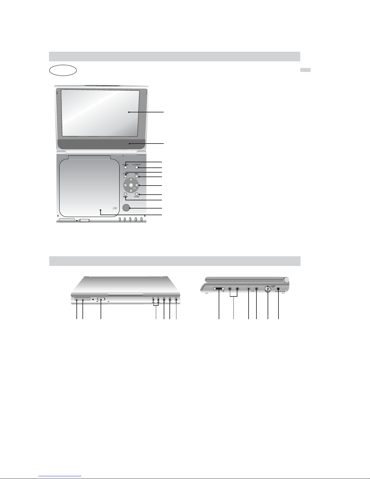
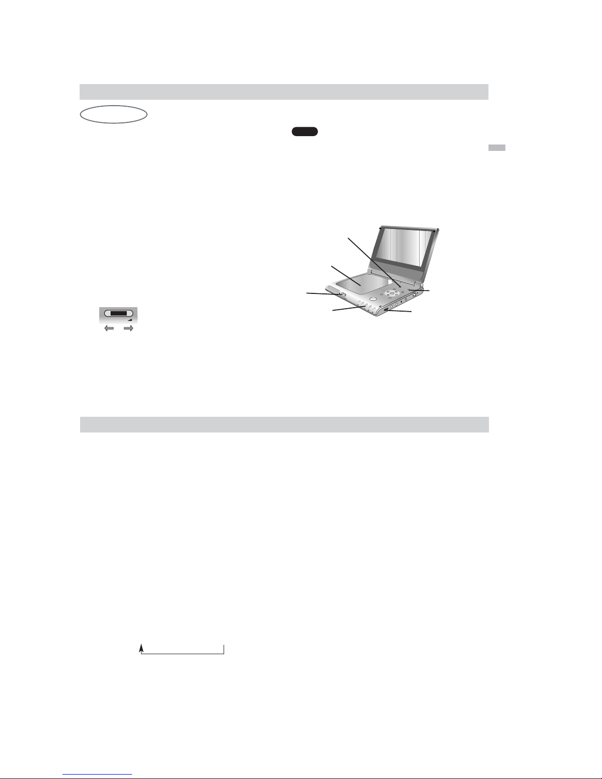
Identification of Controls
Main Unit
OPEN
1
2
4
5
3
1. LCD screen
2. Speaker
3. LCD MODE (page 25)
4. COLOR/BRIGHT (page 24)
Brightness → Color → OFF
5. TOP MENU (page 30)
displays the title menu.
6. MENU (page 30)
displays menu programs.
7. B/V/v/b button, ENTER button
8. RETURN button
9. DISPLAY (page 28-29)
operation mode display.
10.OPEN button (page 23)
Push this button to open the Disc lid.
11.Disc Lid (page 23)
NOTE:
Place a disc with the playback side down on the
spindle, and push gently on the center of the disc so
it goes into position.
6
7
8
9
10
11
16
Identification of Controls (continued)
POWER /HOLD
VOLUME PHONESPHONES AUDIO VIDEO
1 2 3 4 5 6 7 8 9 10 11 12 13
1. Power indicator (page 23)
POWER ON: Green ON
POWER OFF: Green OFF
2.
CHARGE indicator
(page 22)
During recharging: Orange ON
3.
POWER and HOLD switch
To turn off the power, you need to press the
POWER switch for at least one second. This is to
prevent the player from being accidentally turned
off.
HOLD switch
• The hold function locks the buttons on the DVD player so that
they will not work if accidentally touched.
• To enable, slide the HOLD switch on the right side of the DVD
player to the HOLD position.
• To disable, slide the switch back to its original position.
4. PREV/NEXT buttons (page 30)
5. PLAY button (page 23)
6. PAUSE button (page 27)
7. STOP button
8. VOLUME dial (page 23)
9. PHONES connector
10.AUDIO OUT connector (page 47)
11. VIDEO OUT connector (page 47)
12.S-VIDEO OUT connector (page 47)
13.DC IN 9.8V connector (page 20)
Connect the AC adaptor.
1-7
Introductions
1717
Identification of Controls (continued)
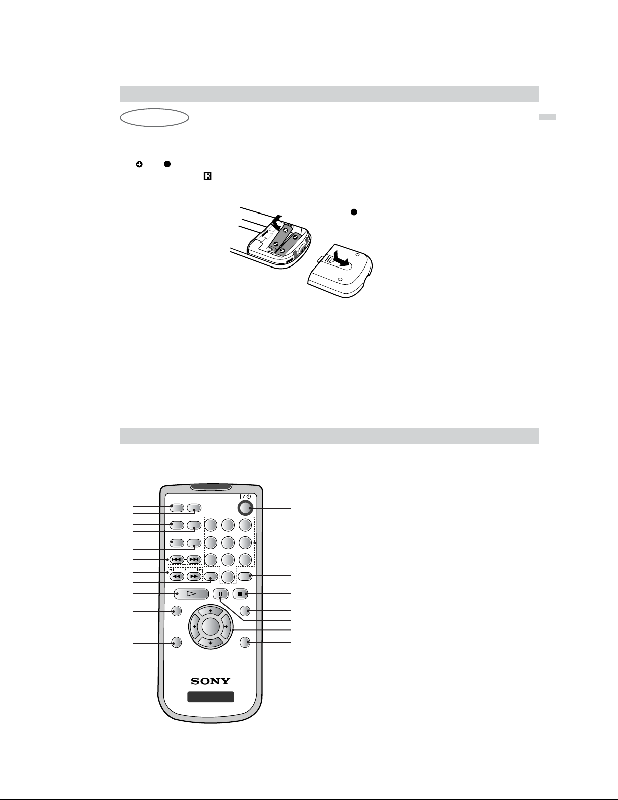
Inserting batteries into the remote
You can control the player using the supplied remote. Insert two size AA(R6) batteries (supplied) by matching
the and ends on the batteries to the markings inside the compartment. When using the remote, point it
at the remote sensor on the player.
Insert the end first
NOTES:
• Do not leave the remote in an extremely hot or humid place.
• Do not drop any foreign object into the remote casing, particularly when replacing the batteries.
• Do not expose the remote sensor to direct light from the sun or lighting apparatus. Doing so may cause a malfunction.
• If you do not use the remote for an extended period of time, remove the batteries to avoid possible damage from battery
leakage and corrosion.
Remote Control
18
Identification of Controls (continued)
AUDIO
PREV NEXT
CLEAR
PLAY PAUSE STOP
SET UP
SCAN
TOP MENU
MENU
DISPLAY RETURN
SLOW
REPEAT
RANDOM
A-B
PROGRAM
ANGLE
123
654
7
8
0
9
DVD PORTABLE
ENTER
1
2
3
4
5
6
7
8
10
11
12
13
14
15
16
17
20
1. AUDIO button (page 31)
2. ANGLE button (page 31)
3. REPEAT button (page 32)
4. PROGRAM button (page 36-37)
5. RANDOM button (page 38)
6. A-B button (page 32)
7. PREV/NEXT button (page 30)
8. SCAN/SLOW button (page 27)
9. CLEAR button
10.PLAY button
11.* TOP MENU button (page 30)
12.DISPLAY button (page 28-29)
13.POWER button
14.NUMBER buttons
15.SET UP button (page 41)
9
18
19

1-8
Introductions
19
Identification of Controls (continued)
16.STOP button
17.MENU button
Use the MENU button to display the menu
screen included on a DVD disc.
To operate a menu screen, follow the
instructions in “Using a DVD Menu” (page 30).
18.PAUSE button
19.B/V/v/b button, ENTER button
(up, down, left, right) for use in highlighting a
selection on a GUI menu screen, TOP MENU
and MENU screen.
20.RETURN button
* TOP MENU button:
Use the TOP MENU button to display the title screen
included on DVD video discs. To operate a menu
screen, follow the instructions in “Using a Title Menu”
(page 30).
20
Power Connections
AC Adaptor
To DC IN 9.8V
1
2
3
AC power cord
To AC outlet
VOLUME PHONESPHONES AUDIO VIDEO
AC adaptor (supplied)
Follow steps 1 to 3 to connect.
When disconnecting, reverse the order.
NOTES:
•When you disconnect the AC power cord, be sure to stop playback.
•Disconnecting the AC power cord during playback may cause a malfunction.
1-9
Introductions
Power Connections (continued)
21
Battery Pack
You can use the NP-FX105 rechargeable battery pack
(supplied) to enjoy the player when an AC outlet is not
available.
• Charge the battery pack before using it for the first
time.
A
Attaching the battery pack (supplied)
1. Match the hooks of the battery pack into the
holes on the bottom of the player.
2. Press and slide the battery pack until the hooks
click.
NOTES:
• Do not detach the battery pack during playback.
• Be careful not to drop the battery pack.
A
Detaching the battery pack
1. Press the RELEASE knob.
2. Slide the battery pack until the hooks click.
1
2
RELEASE knob
1
2
Hooks
NOTE:
If you use the main unit without the battery pack, use the
tab on the player to keep it from tipping over.
22
Power Connections (continued)
A
Charging the battery pack
1. Attach the battery pack to the player.
2. Connect the AC adaptor to the player and then
plug into an AC outlet.
When charging starts, the charge indicator lights up
in orange.
3. During recharging, the charge indicator lights up
in orange. When recharging is complete, the
indicator turns off.
4.
Disconnect the AC adaptor from the player and
pull out the plug from the AC outlet after charging.
A
Confirm the battery charge on the LCD screen
during stop or playback. When
“”
appears,
the charge indicator flashes in orange.
The battery mark does not appear during DVD or
JPEG playback. To check the battery charge,
stop playback
•
If using the AC adaptor, battery display does not
appear.
A
Recharging and play times
* When Brightness control is set to “ b ”(minimum).
- using the headphones.
- at room temperature (25°C)
NOTES:
• Recharging times shown above depend on operating
conditions.
• When the power is ON, you cannot charge the
battery.
• Charge the battery at a temperature of +5°C (+41°F)
to +35°C (+95°F).
The charging time may vary, depending on the
surrounding temperature.
• The battery will not be charged when it is naturally or
purposely discharged. Because the unit cannot
perceive battery voltage, even if you attached the
battery.
When you are in this situation, power on the unit and
then power off again. Then battery charging will
proceed.
V
OLU
ME
PHO
NE
S
PHON
ES
AUDIO
V
ID
EO
POWER
/HOLD
Player
AC adaptor cord insert
jack (DC IN 9.8V)
Recharging Play time (DVD-VIDEO)
with player LCD On
Approx. Approx.
4 hours 3 hours*
Full Low
Recharge
Charge indicator
Battery Pack
1-10
Playing a Disc
- Prepare the power supply.
1. Open the outer cover and slide the POWER
switch to the left to turn the unit on.
The power indicator lights up in green.
2.
Press OPEN to open the disc lid and insert a disc
onto the side you want to play, label up. Close the
disc lid by hand.
• If the disc is placed in upside down (and it is a single-
sided disc), “NO DISC” or “Disc Error” appears on the
LCD screen.
3. Press PLAY to start play.
• After playing back all of the chapters in the title, the
DVD player automatically stops and returns to the
menu screen.
4. Adjust the volume.
•Reduce the volume before playback, then gradually
increase it.
After operation
When the unit is not in use, remove the disc and slide the
POWER switch to the left and hold it there to turn off the
DVD player.
The power indicator turns off.
When a menu screen appears on the LCD
screen.
In case of interactive DVDs with control,
a menu screen appears on the LCD screen.
Press B/V/v/b and press ENTER, or press the number
buttons, to select the desired item.
Playback of the selected item begins.
For further information, also refer to the jacket or case of
the disc you are playing.
DVD
23
Basic Playback
1
2
3
4
LCD MODE
COLOR/BRIGHT
VOLUME
Down Up
Basic Operation
24
Playing a Disc (continued)
NOTES:
•Place a disc with the playback side down on the
spindle, and push gently on the center of the disc
so it goes into position.
•
Confirm LCD MODE position by pressing LCD MODE
button.
• If parental control is set and the disc is not within
the rating settings you must input the password.
(See “PARENTAL CONTROL” on page 44-45.)
• DVDs may have a region code. Your player does
not play discs that have a region code different
from your player.
Adjusting the brightness and color intensity
Use the COLOR/BRIGHT button to adjusting the
brightness and color intensity.
Each time you press the button, the adjustment
mode changes as follows.
Brightness → Color → OFF
Adjusting the brightness
Select “Brightness” and then press
B/b
to adjust the
brightness.
b ; dark
B ; light
Adjusting color intensity
Select “Color” and then press
B/b
to adjust the color
intensity.
b ; darker colors
B ; lighter colors
NOTES:
•
This COLOR/BRIGHT button adjusts only the image on
the LCD screen.
•
Power consumption increases with the level of
brightness.

1-11
Basic Operation
Playing a Disc (continued)
25
A
Changing the size of the picture
Use the LCD MODE button to change the picture mode.
DVD disc Audio CD/ MP3 disc/ JPEG disc (Menu)
NORMAL → FULL → ZOOM → LCD OFF FULL → LCD OFF
JPEG disc (Slide show)
NORMAL → FULL → LCD OFF
NOTES:
• The picture mode will appear differently for different kinds of discs.
• If you play back an image that was recorded in Widescreen (16:9) mode and “TV Aspect” in “SET UP” is
set to “16:9 Wide”, then the LCD MODE button will only switch between FULL, ZOOM and LCD OFF.
A
The picture mode and size
The picture shown on the LCD depends on the display mode and the size recorded on the disc.
NOTES:
• If you are not using the LCD on this unit, select OFF to conserve power.
• The LCD is turned off if you close the unit.
• Horizontal lines may appear in the picture when the mode is switched to ZOOM,
but this is not an indication of a malfunction.
Playing a Disc (continued)
26
Stopping Play
Press STOP during playback.
NOTE:
Do not touch the disc if it is still spinning when you open
the lid.
Resume Play
When play is stopped, the unit records the point
where STOP was pressed (RESUME function).
Press PLAY and play will resume from this point.
NOTES:
•
When you press the STOP button, RESUME x (stop)
appears on the LCD screen and the player enters the
resume mode.
•
For MP3/JPEG data no information may be displayed
depending upon the condition of the disc. .
Screen Saver
The screen saver appears when you leave the
player in Stop mode for about 15 minutes. If the
Screen Saver is displayed for 15 minutes, the Player
automatically turns itself off.
1-12
Basic Operation
Playing a Disc (continued)
27
Pause
1. Press PAUSE during playback.
2. To exit still motion mode, press PLAY.
Search
1. Press SCAN/SLOW m or M during playback.
The player will now go into SEARCH mode.
2. Press SCAN/SLOW m or M repeatedly to
select the required speed: X2b, 1m, 2m,
3m (backward) or X2B, 1M, 2M, 3M
(forward).
3. To exit SEARCH mode, press PLAY.
NOTE:
The DVD player does not play back sound during the high
speed reverse and forward playback of DVD video discs.
Slow Motion
1. Press PAUSE(X) during playback.
The player will now go into PAUSE mode.
2. Use the SCAN/SLOW m or M to select the
required speed:
4, 3, 2, 1(backward),
or 4 , 3 , 2 , 1 (forward).
3. To exit slow motion mode, press PLAY.
DVD
DVD
DVD
On-Screen Display
28
You can display the general playback status on the
screen. Some items can be changed using the
menu. To use the on-screen display:
1. Press DISPLAY during playback.
2. Press V/v to select an item.
The selected item is highlighted.
3. Press B/b to change the setting. You can also
use the number buttons if appropriate (e.g.
inputting the title number).
For some functions, press ENTER to execute the
setting.
NOTES:
• Some discs may not provide all of the features shown
next page.
• If no button is pressed for 10 seconds,
the on-screen display disappears.
AUDIO
PREV NEXT
CLEAR
PLAY PAUSE STOP
SET UP
SCAN
TOP MENU
MENU
DISPLAY RETURN
SLOW
REPEAT
RANDOM
A-B
PROGRAM
ANGLE
123
654
7
8
0
9
DVD PORTABLE
ENTER
1
2, 3
1-13
Basic Operation
On-Screen Display (continued)
29
Items
Title Number
Chapter Number
Time search
Audio language
and Digital Audio
Output mode
Subtitle language
Angle
Selection Method
B/b
, Numbers
ENTER
B/b
, Numbers
ENTER
Numbers, ENTER
B/b
or
AUDIO
B/b
B/b
or
ANGLE
1 / 3
1 / 12
0:20:09
1 ENG
1 / 3
Example: On-Screen Display during
playing of DVD Video
Title Menu
Checking the contents of DVD discs: Menus
DVDs may offer menus that allow you to access
special features. To use the disc menu,
press TOP MENU. Input the corresponding number
or use the B/V/v/b buttons to highlight your
selection.
Then press ENTER.
DVD Menu
1. Press MENU. If the current title has a menu, the
menu appears on the screen. Otherwise, the disc
menu may appear.
2. The menu offers features such as camera
angles, spoken language and subtitle options,
and chapters for the title.
Press B/V/v/b and ENTER, or press the numeric
button(s), to select desired item.
Unless stated otherwise, all operations described
use the remote control. Some features may also
be available on the Setup menu.
Moving to another TITLE
When a disc has more than one title, you can move
to another title. Press DISPLAY while playback is
stopped then the appropriate number (0-9) or use
B/b to move to another title.
You can play any title by inputting its number while
playback is stopped.
Moving to another CHAPTER
When a title on a disc has more than one chapter,
you can move to another chapter as follows:
•Press PREV/NEXT . or > briefly during
playback to select the next chapter or to return to
the beginning of the current chapter.
•Press PREV . twice briefly to step back to the
previous chapter.
•To go directly to any chapter during DVD
playback, press DISPLAY and press V/v to
select the chapter icon. Then, input the chapter
number or use B/b.
DVD
DVD
DVD
DVD
General Features
30

1-14
Advanced Operations
General Features (continued)
Time Search
To start playing at any chosen time on the disc:
1. Press DISPLAY during playback. The time
search box shows the elapsed playing time.
2. Press V/v to select the time clock icon
and “-:--:--” appears.
3. Input the required start time in hours, minutes,
and seconds from left to right. If you enter the
wrong numbers, press CLEAR to remove the
numbers you entered. Then input the correct
numbers.
4. Press ENTER to confirm. Playback starts from
the selected time.
NOTE:
The Time Search function may not be available on some
DVD discs.
Changing the Audio Language
Press AUDIO repeatedly during playback to hear a
different audio language or audio track.
This operation works only with discs on which
multiple audio soundtrack languages are recorded.
Subtitles
It is possible to change the subtitle language to a
different language from the one selected at the initial
settings. (See page 41 for further info.)
This operation works only with discs on which
multiple subtitle languages are recorded.
1. Press DISPLAY during playback.
2. Press V/v to select the subtitle item.
3. Press B/b repeatedly until the desired Subtitle is
selected. Each time this button is pressed, the
LCD screen display changes.
Camera Angle
If the disc contains scenes recorded at different
camera angles, you can change to a different
camera angle during playback.
1. Press ANGLE during playback.
2. Press B/b repeatedly until the desired Angle is
selected.
NOTE:
You cannot change the angle during slow playback.
TIP:
The angle indicator will blink on the screen during scenes
recorded at different angles as an indication that angle
switching is possible.
DVD
DVD
DVD
DVD
31
General Features (continued)
32
Repeat A-B
To repeat a sequence.
1. Press A-B during playback at your chosen
starting point. “ A*” appears briefly on the
screen.
2. Press A-B again at your chosen end point.
“A B” appears briefly on the screen and the
repeat sequence begins.
3. Press A-B again to cancel.
NOTE:
A-B repeat can only be used within a single title.
Repeat
Each time this button is pressed, the LCD screen
changes as shown below and the disc will repeat a
chapter or title (DVD).
DVD Video Discs - Repeat Chapter/Title/Off
• Chapter : repeats the current chapter.
• Title : repeats the current title.
• Off : does not play repeatedly.
NOTES:
• If you press NEXT (>) once during Repeat Chapter
playback, the repeat playback cancels.
• Repeat play may not work correctly with some DVDs .
DVDDVD
1-15
Advanced Operations
Playing an Audio CD or MP3 Disc
33
This player can play MP3 formatted recordings on
CD-ROM, CD-R, or CD-RW discs.
Audio CD
Once you insert an audio CD a menu appears on
the screen. Press V/v to select a track then press
PLAY or ENTER and playback starts.
MP3
1. Press V/v to select a folder, and press ENTER to
see the folder contents.
2. Press V/v to select a track then press PLAY or
ENTER. Playback starts.
ID3 TAG (Version 1)
•When playing a file containing information such as
track titles, you can see the information by
pressing DISPLAY.
[ Title, Artist, Album, Year, Comment ]
• If there is no information, “No ID3 TAG” appears
on the display.
TIPS:
•
If you are in a file list on the AUDIO menu and want to
return to the Folder list, use the
V/v
to highlight and
press ENTER.
• Press MENU to move to the next page.
• On a CD with MP3 and JPEG you can switch MP3 and
JPEG. Press TOP MENU and AUDIO or IMAGE word on
top of the menu is highlighted.
Track01
Track02
Track03
Track04
Track05
Track06
Track07
Track08
AUDIO CD
0:52:07
1 / 12
Clear All
Program
List
0:00:00
1 / 12
Clear All
AUDIO
2-Music02
1-Music01
3-Music03
4-Music04
5-Music05
6-Music06
7-Music07
Program
List
/MP3
Playing an Audio CD or MP3 Disc
(continued)
34
Audio CD and MP3 Disc Features
Pause
1. Press PAUSE during playback.
2. To return to playback, press PLAY, ENTER or
press PAUSE again.
Moving to another Track
1. Press PREV/NEXT (. or >) briefly during
playback to go to the next track or to return to the
beginning of the current track.
2. Press PREV . twice briefly to go back to the
previous track.
3. You can play any track by inputting its number.
Search
1. Press SCAN/SLOW (
m
or M) during playback.
The player will now go into SEARCH mode.
2. Press SCAN/SLOW (
m
or M) repeatedly to
select the required speed: 1m,2m, 3m
(backward) or 1M, 2M, 3M (forward).
Search speed and direction are indicated on the
menu screen.
3. To exit SEARCH mode, press PLAY.
Repeat Track/All/Off
You can play a track/all on a disc.
1. Press REPEAT when playing a disc.
The repeat icon appears.
2. Press REPEAT to select a desired repeat mode.
• Track : repeats the current track
• All : CD: repeats all the tracks on a disc.
MP3 : repeats all the tracks in a folder.
• Off(No display) : does not play repeatedly.
NOTE:
If you press NEXT (>) once during Repeat Track playback, the repeat playback cancels.
Repeat A-B
1. To repeat a sequence during disc playback,
press A-B at your chosen starting point. The
Repeat icon and “A” appear on the menu screen.
2. Press A-B again at your chosen end point.
The Repeat icon and “A-B” appear on the menu
screen, and the sequence begins to play
repeatedly.
3. To exit the sequence and return to normal play,
press A-B again. The Repeat icon disappears
from the menu screen.
CD
MP3CD
MP3CD
MP3CD
MP3CD

1-16
Advanced Operations
Playing an Audio CD or MP3 Disc
(continued)
35
MP3 disc compatibility with this player is limited
as follows:
•Sampling frequency: within 8 - 48 kHz (MP3)
•Bit rate: within 8 - 320kbps (MP3)
• The player cannot read an MP3 file that has a file
extension other than “.mp3”.
• CD-R physical format should be ISO 9660.
• If you record MP3 files using software that cannot create a file system (eg. Direct-CD), it is impossible to
playback MP3 files. We recommend that you use EasyCD Creator, which creates an ISO 9660 file system.
•File names should have a maximum of 8 letters and
must incorporate an .mp3 extension.
• They should not contain special letters such as / ? * : “
< > l etc.
• The total number of files on the disc should be about
600.
This DVD player requires discs and recordings to
meet certain technical standards in order to achieve
optimal playback quality. Pre-recorded DVDs are
automatically set to these standards. There are
many different types of recordable disc formats
(including CD-R containing MP3 files) and these
require certain pre-existing conditions (see above)
to ensure compatible playback.
AMulti-session recording is not ensured.
Customers should note that permission is
required in order to download MP3 files and
music from the Internet. Our company has no
right to grant such permission. Permission
should always be sought from the copyright
owner.
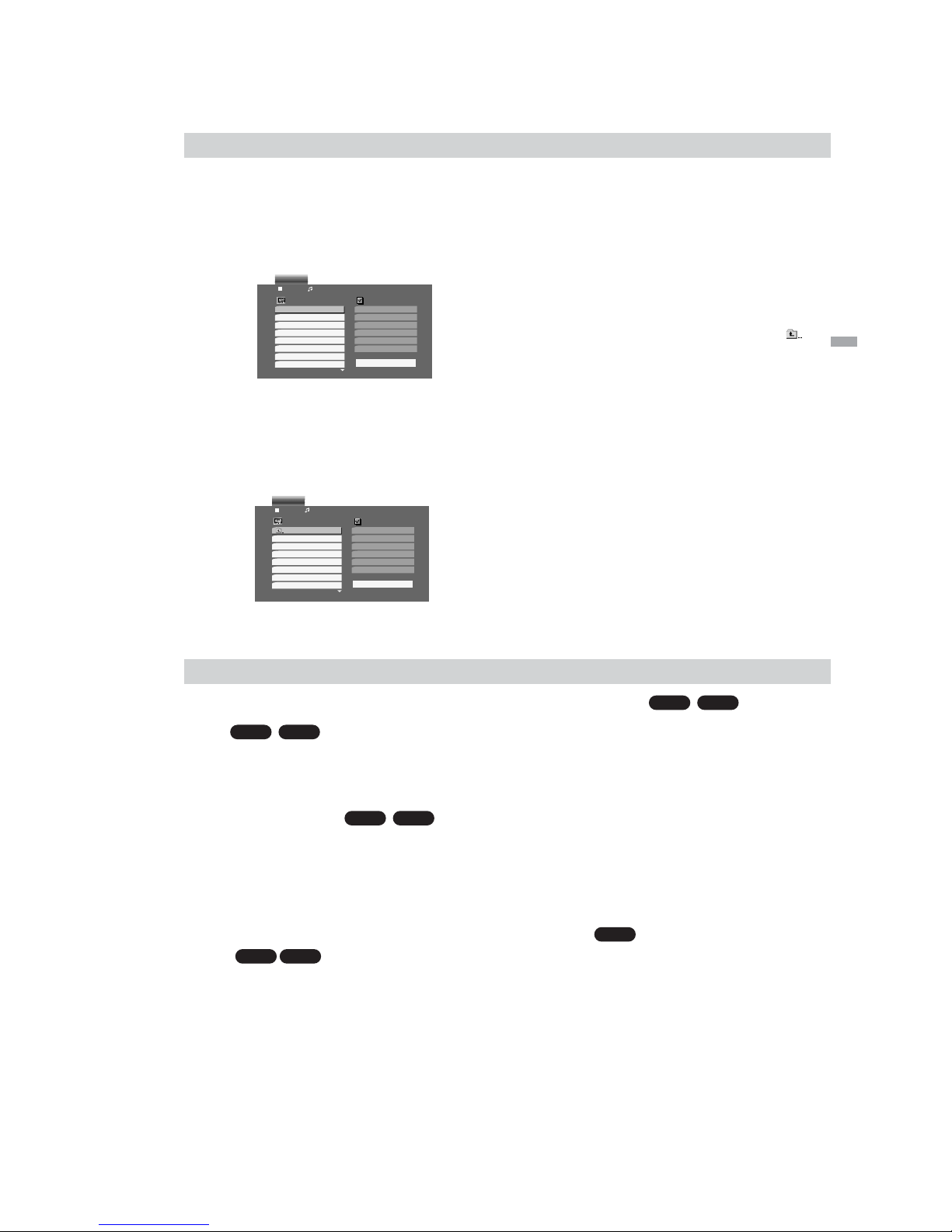
Programmed Playback
36
The program function enables you to store the
playback order of your favorite tracks from any disc
in the player memory.
A program can contain 30 tracks.
1. Insert a disc.
Audio CD or MP3 Discs:
AUDIO CD or AUDIO menu appears.
2. Press PROGRAM.
The mark will appear to the right of the word
“Program” on the right side of the menu screen.
NOTE:
Press PROGRAM. again, then the mark will
disappear to exit the Program Edit mode.
Audio CD Menu MP3 Menu
3. Select a track on the “List”, then press ENTER to
place the selected track on the “Program” list.
Repeat to place additional tracks on the list.
4. Press b.
Select the track you want to start playing on the
“Program” list.
5. Press PLAY or ENTER to start. Playback begins
in the order in which you programmed the tracks.
Playback stops after all of the tracks on the
“Program” list have played once.
6. To resume normal playback from programmed
playback, select any track from the AUDIO list
and then press PLAY.
Track01
Track01
Track04
Track07
Track05
Track02
Track03
Track04
Track05
Track06
Track07
Track08
AUDIO CD
0:52:07
1 / 12
Clear All
Program
List
0:00:00
1 / 12
Clear All
AUDIO
2-Music02
2-Music02
4-Music04
6-Music06
1-Music01
1-Music01
3-Music03
4-Music04
5-Music05
6-Music06
7-Music07
Program
List
/MP3

1-17
Advanced Operations
Programmed Playback (continued)
37
Repeat Programmed Tracks
1. Press REPEAT when playing a disc. The repeat
icon appears.
2. Press REPEAT to select a desired repeat mode.
• Track: repeats the current track
• All: repeats all the tracks on programmed list.
• Off(No display): does not play repeatedly.
NOTE:
If you press > once during Repeat Track playback, the
repeat playback cancels.
Erasing a Track from Program List
1. Press PROGRAM.
2. Use V/v/b to select the track that you wish to
erase from the Program list.
3. Press CLEAR. Repeat to erase additional tracks
on the list.
Erasing the Complete Program List
1. Press PROGRAM.
2. Press b to move to the “Program” list.
3. Use V/v to select “Clear All”, then press ENTER.
NOTE:
The programs are also cleared when the disc is removed.
38
Random Play
Random play (Karaoke DVD, CD, MP3)
You can playback titles or tracks in random order.
(Random playback)
NOTE:
Random does not work with DVD movie discs.
1. Press RANDOM during playback.
This player automatically starts random playback
and the RANDOM indicator appears on the LCD
screen.
2. To return to normal play.
Press RANDOM again.
NOTES:
• RANDOM playback may not be possible on certain discs.
• If you press the > or . button during random
playback, the DVD player goes to another track randomly
and starts playback.

1-18
Advanced Operations
39
Viewing a JPEG Disc
Using this DVD Player you can view discs with
JPEG files.
1. Insert a disc and close the tray.
The IMAGE menu appears on the screen.
2. Press V/v to select a folder, and press ENTER.
A list of files in the folder appears. If you are in a
file list and want to return to the previous Folder
list, use the V/v buttons on the remote to
highlight and press ENTER.
3. If you want to view a particular file, press V/v to
highlight a file and press ENTER or PLAY.
Viewing of the file starts.
While viewing a file, you can press STOP to
move to the previous menu (IMAGE menu).
TIPS:
• Press MENU to move to the next page.
• There are three Slide Speed options
: >>> (Fast), >> (Normal), and > (Slow).
Use
B/V/v/b to highlight the Speed. Then use B/b to
select the option you want to use and press ENTER.
•On a disc with MP3 and JPEG you can switch MP3 and
JPEG. Press TOP MENU and AUDIO or IMAGE word on
top of the menu is highlighted.
Slide Show
Use B/V/v/b to highlight the (Slide Show)
then press ENTER.
Still Picture
1. Press PAUSE during slide show.
The player will now go into PAUSE mode.
2. To return to the slide show, press PLAY or press
PAUSE again.
JPEG
JPEG
Preview
List
JPEG Folder 1
JPEG Folder 2
JPEG Folder 3
JPEG Folder 4
JPEG Folder 5
JPEG Folder 6
JPEG Folder 7
JPEG Folder 8
IMAGE
40
Viewing a JPEG Disc (continued)
Moving to another File
Press PREV/NEXT (. or >) or cursor (B or b)
once while viewing a picture to advance to the next
or previous file.
To rotate picture
Press V/v while showing a picture to rotate the
picture clockwise or counterclockwise.
To listen to MP3 music while watching a picture
You can display files while listening to MP3 music
files recorded on the same disc.
1. Insert the disc containing the two types of files in
the player.
2. Press TOP MENU to display IMAGE menu.
3. Press V/v to select a photo file.
4. Use b to select icon then press ENTER.
Playback starts. When the JPEG file display
ends, MP3 playback will stop as well.
TIP:
To listen to only the desired music watching a picture,
program the desired tracks from the “AUDIO” menu and
then proceed as above.
JPEG disc compatibility with this player is
limited as follows:
•Depending upon the size and number of JPEG files, it
could take a long time for the DVD player to read the
disc’s contents. If you don’t see an on-screen display
after several minutes, some of the files may be too
large — reduce the resolution of the JPEG files to less
than 2M pixels as 2760 x 2048 pixels.
• The total number of files and folders on the disc should
be about 600.
• Some discs may be incompatible due to a different
recording format or the condition of disc.
• Ensure that all the selected files have the “.jpg”
extensions when copying into the CD layout.
• If the files have “.jpe” or “.jpeg” extensions, please
rename them as “.jpg” files.
• File names without “.jpg” extension will not be able to
be read by this DVD player. Even though the files are
shown as JPEG image files in Windows Explorer.
JPEG
JPEG

1-19
41
Initial Settings
By using the Setup menu, you can make various
adjustments to items such as picture and sound. You
can also set a language for the subtitles and the
Setup menu, among other things. For details on
each Setup menu item, see pages 41 to 46.
To display and exit the Menu:
Press SETUP to display the menu. A second press
of SETUP will take you back to initial screen.
To go to the next level:
Press b on the remote control.
To go back to the previous level:
Press B on the remote control.
General Operation
1. Press SETUP. The Setup menu appears.
2. Use V/v to select the desired option then press b
to move to the second level. The screen shows
the current setting for the selected item, as well
as alternate setting(s).
3. Use V/v to select the second desired option then
press b to move to the third level.
4.
Use
V/v
to select the desired setting then press
ENTER to confirm your selection. Some items
require additional steps.
5. Press SETUP or PLAY to exit the Setup menu.
LANGUAGE SET UP
Menu Language
Select a language for the Setup menu and
on-screen display.
Disc Audio / Subtitle / Menu
Select the language you prefer for the audio track
(disc audio), subtitles, and the disc menu.
Original: Refers to the original language in which
the disc was recorded.
Other:
To select another language, press number
buttons then ENTER to enter the corresponding 4-digit
number according to the language code list in the
reference chapter. If you enter the wrong language
code, press CLEAR.
(See “Language Code List”, page53.)
DVD
Menu Language
Original
English
Off
Original
Disc Audio
Disc Subtitle
Disc Menu
LANGUAGE
ENTER
Initial Settings
42
Initial Settings (continued)
SCREEN SET UP
TV Aspect
4:3:
Select when a standard 4:3 TV is connected.
16:9 Wide: Select when a 16:9 wide TV is
connected.
Display Mode
Display Mode setting works only when the TV Aspect
mode is set to “4:3”.
LetterBox: Displays a wide picture with bands on
the upper and lower portions of the screen.
Panscan:
Automatically displays the wide picture on
the entire screen and cuts off the portions that do not
fit.
DVD
DVD
DISPLAY
TV Aspect
Widescreen
16 : 9 Wide
Display Mode
ENTER

1-20
Initial Settings
43
Initial Settings (continued)
AUDIO SET UP
Each DVD disc has a variety of audio output options.
Set the player’s AUDIO SET UP options according to
the type of audio system you use.
Dynamic Range Control (DRC)
With the DVD format, you can hear a program’s
soundtrack in the most accurate and realistic
presentation possible, thanks to digital audio
technology. However, you may wish to compress the
dynamic range of the audio output (the difference
between the loudest sounds and the quietest ones).
This allows you to listen to a movie at a lower
volume without losing clarity of sound. Set DRC to
On for this effect.
NOTE:
• The DRC function works only during playback of Dolby
Digital recorded discs.
• The Level of Dynamic Range Compression may differ
depending on the DVD disc.
DVD
OnDRC
AUDIO
ENTER
44
Initial Settings (continued)
PARENTAL CONTROL
Rating
Some movies contain scenes that may not be suitable for children to view. Many of these discs contain
parental control information that applies to the complete disc or to certain scenes on the disc. Movies
and scenes are rated from 1 to 8, depending on the
country. Some discs offer more suitable scenes as
an alternative.
The parental control feature allows you to block
access to scenes below the rating you input, thereby
preventing your children from being able to view
material you believe is unsuitable.
1. Select “Rating” on the PARENTAL CONTROL
menu then press b.
2. To access the Rating, Password, and Country
Code features, you must input the 4-digit security
code you created. If you have not yet entered a
security code you are prompted to do so.
Input a 4-digit code and press ENTER. Enter it
again and press ENTER to verify. If you make a
mistake before pressing ENTER, press CLEAR.
3. Select a rating from 1 to 8 using the V/v buttons.
Rating 1-8: Rating one (1) has the most
restrictions and rating eight (8) is the least
restrictive.
Unlock
If you select unlock, parental control is not active
and the disc plays in full.
NOTE:
If you set a rating for the player, all disc scenes with the
same rating or higher are played. Lower rated scenes are
not played unless alternate scenes are available on the
disc. The alternatives must have the same or a higher
rating. If no suitable alternative is found, playback stops.
You must enter the 4-digit password or change the rating
level in order to play the disc.
4. Press ENTER to confirm your rating selection,
then press SETUP to exit the menu.
DVD
LOCK
Rating
New
U S
Unlock
Password
Country Code
ENTER

1-21
Initial Settings
45
Initial Settings (continued)
Password (Security Code)
You can enter or change password.
1. Select Password on the PARENTAL CONTROL
menu then press b.
2. Follow step 2 as shown left (Rating). “Change” or
“New” is highlighted.
3. Enter the new 4-digit code, then press ENTER.
Input it again to verify.
4. Press SETUP to exit the menu.
If you forget your Security Code
If you forget your security code you can clear it using
the following steps:
1. Open disc lid.
2. Press SETUP to display the Setup menu.
3. Input the 6-digit number “210499” and the
security code is cleared.
4. Enter a new code as described above.
Country Code
Enter the code of the country/area whose standards
were used to rate the DVD video disc, based on the
list in the reference chapter.
(See “Country Code List”, page 54.)
1. Select “Country Code” on the
PARENTAL CONTROL menu then press b.
2. Follow step 2 as shown left (Rating).
3. Select the first character using V/v buttons.
4. Press ENTER and select the second character
using V/v buttons.
5. Press ENTER to confirm your country code
selection.
DVD
46
Initial Settings (continued)
CUSTOM SETUP
The BLACK LEVEL settings can be changed.
BLACK LEVEL
Selects the black level(setup level) for the video signals output from the jacks (Video output and S-video
output) and LCD screen.
On: Sets the black level of the output signal to the
standard level.
Off: Lowers the standard black level.
Use when the picture becomes too white.
BLACK LEVEL
OTHERS
On
ENTER
1-22
Setting up the Player
The picture and sound of a nearby TV, VCR, or radio
may be distorted during playback. If this occurs,
position the player away from the TV, VCR, or radio,
or turn off the unit after removing the disc.
DVD Player Connections
Depending on your TV and other equipment, there
are various ways you can connect the player. Please
refer to the manuals of your TV, stereo system, or
other devices as necessary for additional connection
information.
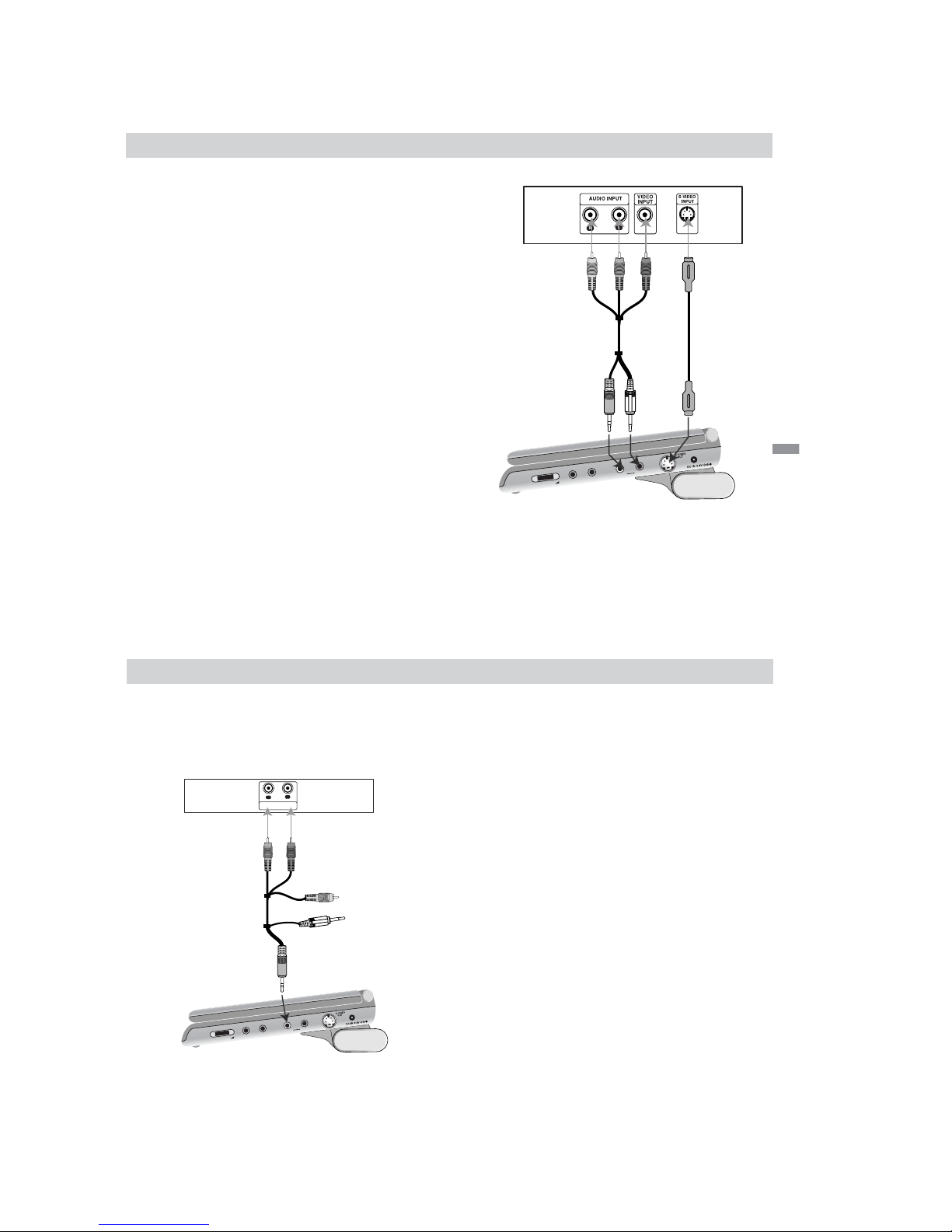
Video and Audio Connections to Your TV
Make sure the DVD player is connected directly to
the TV and not to a VCR, otherwise the DVD image
could be distorted by the copy protection system.
Video: Connect the VIDEO OUT jack on the DVD
player to the VIDEO INPUT jack on the TV using the
video cable.
S-Video: Connect the S-VIDEO OUT jack on the
DVD Player to the S-VIDEO INPUT jack on the TV
using the S-Video cable.
Audio Connection to Your TV:
Connect the AUDIO OUT jack of the DVD Player to
the AUDIO L and R INPUT jacks on the TV using the
audio cables. Do not connect the DVD Player’s
AUDIO OUT jack to the PHONES jack (record deck)
of your audio system.
47
V
O
L
U
M
E
P
H
O
N
E
S
P
H
O
N
E
S
A
U
D
IO
V
ID
E
O
Rear of TV
Right side of unit
Audio/ Video cable
(Supplied)
(Yellow)
S-Video cable
(Not supplied)
Connections
48
Setting up the Player
(continued)
Audio Connection to Optional
Equipment
Connect the DVD player to your optional equipment
for audio output.
Amplifier equipped with 2-channel analog stereo
or Dolby Pro Logic ll / Pro Logic:
Connect the
AUDIO OUT jacks on the DVD player to the audio left
and right IN jacks on your amplifier, receiver, or stereo
system, using the audio cables.
NOTES:
To see the audio format of the current DVD in the
on-screen display, press AUDIO.
V
O
L
U
M
E
P
H
O
N
E
S
P
H
O
N
E
S
A
U
D
IO
V
ID
E
O
Right side of unit
Amplifier (Receiver)
R
L
AUDIO INPUT
Audio/ Video cable
(Supplied)
(Black)

1-23
Connections
49
To use the player with car battery adaptor
NOTES:
• Route the cords so that they will not interfere with driver.
•Turn off the player by Power switch. If you turn off the
player by turning off the ignition key of the car when the
rechargeable battery is not attached, the settings may be
cleared.
• Do not install the monitor display where viewable by the
driver.
• Some states restrict the use of monitors and televisions
in vehicles. Where use is permitted, the units should not
be installed or operated so as to be viewable by the
driver.
• Keep this unit away from Sony DVP-FX705 if the
picture is disturbed.
Connect the player to the cigarette lighter socket using the supplied car battery adaptor (DCC-FX105).
This adaptor can only be used 12V electrical currents. It will not work with 24V electrical currents.
To a cigarette lighter socket
DCC-FX105
(Supplied)
To a DC power input jack
(DC IN 9.8V)
DVP-FX705
50
To use the player with car battery adaptor (continued)
Others
• Use this car battery adaptor only for cars which
use a 12 volt battery.
Do not use this with a car that has a 24 volt
battery.
• There are cars which are negatively grounded and
there are others which are positively grounded.
This car battery adaptor is for negatively
grounded cars only.
• Use the unit with the car engine running.
If you use the unit with the car engine stopped, the
car battery may become unusable.
• This unit is not disconnected from the power
source as long as it is connected to the cigarette
lighter socket of a car.
• Unplug the car battery cord from the cigarette
lighter socket when not in use. To disconnect the
cord, pull it out by the plug. Never pull the cord
itself.
• Do not operate the unit if it has been dropped or
damaged.
• Be sure that nothing metallic comes into contact
with the metal parts of the unit. If it does, a short
may occur and the unit may be damaged.
•Always keep the metal contacts clean.
• If the car’s cigarette lighter socket is dirty with ash,
etc., the plug part will become hot due to a poor
connection. Be sure to clean it before using.
• Do not disassemble or convert the unit.
• Do not apply mechanical shock or drop the unit.
• Heat may build up while charging or during
extented use. This is not a malfunction.
•While listening to the car radio, keep the plug of
the Car Battery Cord out of the cigarette lighter
socket or keep the radio away from the unit to
avoid static.
•Avoid placing it where it would be subject to
vibration.
•Avoid leaving the unit where it would be subject to
high temperatures, such as direct sunlight e.g. on
the dashboard or hot air from the heater.
1-24
51
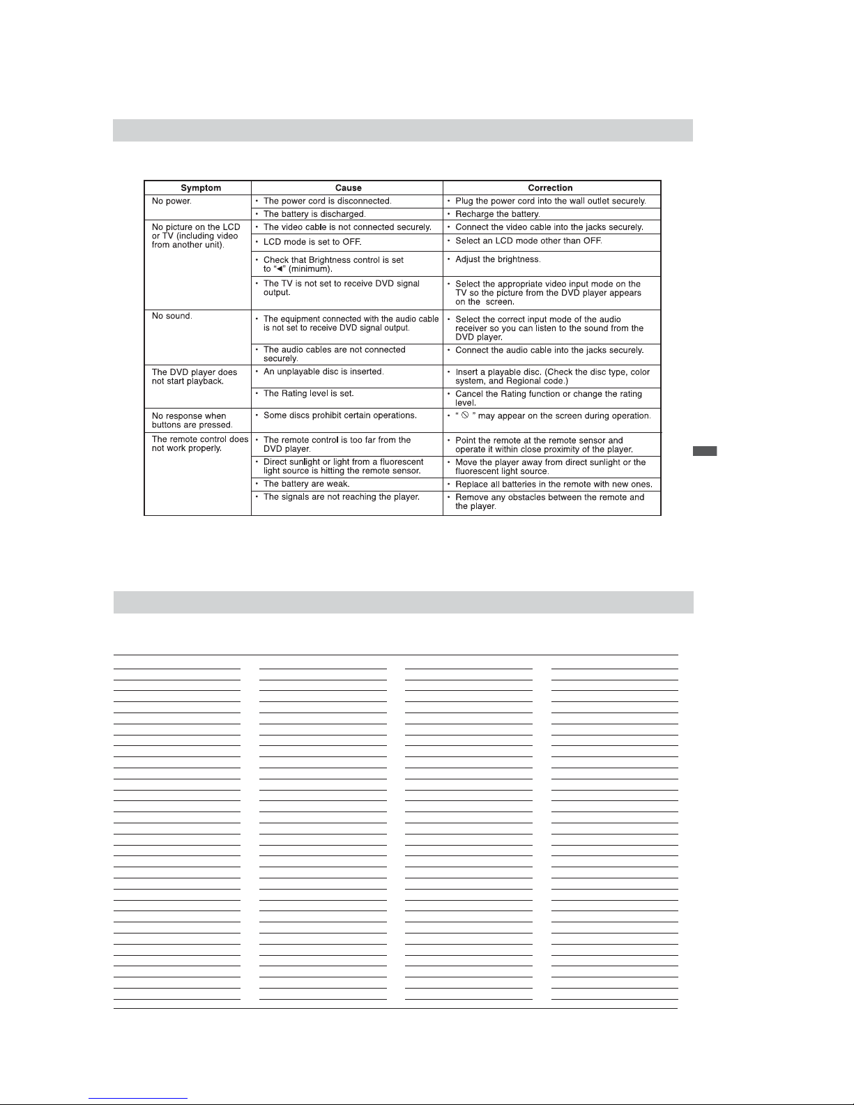
Troubleshooting
Reference
52
Language Code List
Use this list to input your desired language for the following initial settings:
Disc Audio, Disc Subtitle, Disc Menu.
Language Code
Abkhazian 6566
Afar 6565
Afrikaans 6570
Albanian 8381
Ameharic 6577
Arabic 6582
Armenian 7289
Assamese 6583
Aymara 6588
Azerbaijani 6590
Bashkir 6665
Basque 6985
Bengali; Bangla 6678
Bhutani 6890
Bihari 6672
Breton 6682
Bulgarian 6671
Burmese 7789
Byelorussian 6669
Cambodian 7577
Catalan 6765
Chinese 9072
Corsican 6779
Croatian 7282
Czech 6783
Danish 6865
Dutch 7876
English 6978
Esperanto 6979
Estonian 6984
Faroese 7079
Language Code
Fiji 7074
Finnish 7073
French 7082
Frisian 7089
Galician 7176
Georgian 7565
German 6869
Greek 6976
Greenlandic 7576
Guarani 7178
Gujarati 7185
Hausa 7265
Hebrew 7387
Hindi 7273
Hungarian 7285
Icelandic 7383
Indonesian 7378
Interlingua 7365
Irish 7165
Italian 7384
Japanese 7465
Javanese 7487
Kannada 7578
Kashmiri 7583
Kazakh 7575
Kirghiz 7589
Korean 7579
Kurdish 7585
Laothian 7679
Latin 7665
Latvian, Lettish 7686
Language Code
Lingala 7678
Lithuanian 7684
Macedonian 7775
Malagasy 7771
Malay 7783
Malayalam 7776
Maltese 7784
Maori 7773
Marathi 7782
Moldavian 7779
Mongolian 7778
Nauru 7865
Nepali 7869
Norwegian 7879
Oriya 7982
Panjabi 8065
Pashto, Pushto 8083
Persian 7065
Polish 8076
Portuguese 8084
Quechua 8185
Rhaeto-Romance 8277
Romanian 8279
Russian 8285
Samoan 8377
Sanskrit 8365
Scots Gaelic 7168
Serbian 8382
Serbo-Croatian 8372
Shona 8378
Sindhi 8368
Language Code
Singhalese 8373
Slovak 8375
Slovenian 8376
Somali 8379
Spanish 6983
Sudanese 8385
Swahili 8387
Swedish 8386
Tagalog 8476
Tajik 8471
Ta mil 8465
Tatar 8484
Telugu 8469
Thai 8472
Tibetan 6679
Tigrinya 8473
Tonga 8479
Turkish 8482
Turkmen 8475
Twi 8487
Ukrainian 8575
Urdu 8582
Uzbek 8590
Vietnamese 8673
Volapük 8679
Welsh 6789
Wolof 8779
Xhosa 8872
Yiddish 7473
Yoruba 8979
Zulu 9085

1-25
Reference
53
Country Code List
Choose a country code from this list.
Country Code
Afghanistan AF
Argentina AR
Australia AU
Austria AT
Belgium BE
Bhutan BT
Bolivia BO
Brazil BR
Cambodia KH
Canada CA
Chile CL
China CN
Colombia CO
Congo CG
Costa Rica CR
Croatia HR
Czech Republic CZ
Denmark DK
Ecuador EC
Egypt EG
El Salvador SV
Country Code
Ethiopia ET
Fiji FJ
Finland FI
France FR
Germany DE
Great Britain GB
Greece GR
Greenland GL
Islands HM
Hungary HU
India IN
Indonesia ID
Israel IL
Italy IT
Jamaica JM
Japan JP
Kenya KE
Kuwait KW
Libya LY
Luxembourg LU
Country Code
Malaysia MY
Maldives MV
Mexico MX
Monaco MC
Mongolia MN
Morocco MA
Nepal NP
Netherlands NL
Netherlands Antilles AN
New Zealand NZ
Nigeria NG
Norway NO
Oman OM
Pakistan PK
Panama PA
Paraguay PY
Philippines PH
Poland PL
Portugal PT
Romania RO
Russian Federation RU
Country Code
Saudi Arabia SA
Senegal SN
Singapore SG
Slovak Republic SK
Slovenia SI
South Africa ZA
South Korea KR
Spain ES
Sri Lanka LK
Sweden SE
Switzerland CH
Thailand TH
Turkey TR
Uganda UG
Ukraine UA
United States US
Uruguay UY
Uzbekistan UZ
Vietnam VN
Zimbabwe ZW
 Loading...