

Sony DVP-CX870D, RMT-D123A, RMT-D123P, RMT-D124A Service Manual
DVP-CX860/CX870D
RMT-D123A/D123P/D124A
US Model
Canadian Model
DVP-CX860/CX870D
AEP Model
UK Model
DVP-CX860
SERVICE MANUAL
CD/DVD PLAYER
SPECIFICATIONS
CD/DVD player
Laser
Semiconductor laser
Signal format system
NTSC: CX860: US,CND/CX870D
PAL (NTSC): CX860: AEP,UK
Audio characteristics
Frequency response
DVD (PCM 96 kHz): 2 Hz to 44 kHz
(±1.0 dB)* : CX860, (±0.5 dB) : CX870D
DVD (PCM 48 kHz): 2 Hz to 22 kHz
(±0.5 dB)
CD: 2 Hz to 20 kHz (±0.5 dB)
Signal-to-noise ratio
More than 110 dB: CX860
(AUDIO OUT connectors only)
More than 115 dB: CX870D
Harmonic distortion
Less than 0.003 % : CX860
Less than 0.0025 % : CX870D
Dynamic range
More than 100 dB (DVD)
More than 97 dB (CD): CX860
More than 98 dB (CD): CX870D
Wow and flutter
Less than detected value
(±0.001% W PEAK)
Outputs/Inputs
AUDIO OUT
(1, 2)
DIGITAL OUT
(OPTICAL)
DIGITAL OUT
(COAXIAL)
VIDEO
OUTPUT (1, 2)
OUTPUT (1)
S VIDEO
OUTPUT (1, 2)
OUTPUT (1)
COMPONENT
VIDEO OUT
(Y, P
B
, PR)
S-LINK
(CONTROL S
IN)
Jack
type
Phono
jacks
Optical
output
connector
Phono
jack
Phono
jacks
4-pin
mini DIN
Phono
jacks
jack
Mini jack
Output/input
level
2 Vrms
(at 50 kilohms)
–18 dBm
0.5 Vp-p
1.0 Vp-p
Y: 1.0 Vp-p
C: 0.286 Vp-p
Y: 1.0 Vp-p
P
B
, PR:
0.7 Vp-p
–
Load impedance
Over 10 kilohms
2 Vrms
(at 50 kilohms)
Over 10 kilohms
Wave length: 660 nm
75 ohms terminated
75 ohms,
sync negative
75 ohms,
sync negative
75 ohms terminated
C: 0.3 Vp-p 75 ohms terminated
75 ohms,
sync negative
75 ohms
–
*1
*2
*1
*2
*1
*2
*3
WOOFER
OUT
Phono
*3
jack
2 Vrms
(at 10 kilohms)
Over 10 kilohms
5.1 CH
OUTPUT
Phono
*4
General
Power requirements
120 V AC, 60 Hz (CX860: US,CND/CX870D),
220 – 240 V AC, 50/60 Hz (CX860: AEP,UK),
Power consumption
18 W (CX860: US,CND),
Dimensions (approx.)
430 × 158 × 415 mm (17 × 6
1
/4 × 16 3/8 in.)
(w/h/d) incl. projecting parts
Mass (approx.)
7.0 kg (15 lb 7 oz)
Operating temperature
5 ˚C to 35 ˚C (41 ˚F to 95 ˚F)
Operating humidity
25 % to 80 %
Supplied accessories
* The signals from AUDIO OUT connectors are measured. When you
play PCM sound tracks with a 96 kHz sampling frequency, the
output signals from the DIGITAL OUT (OPTICAL, COAXIAL) are
converted to 48 kHz (sampling frequency).
Design and specifications are subject to change without notice.
E
NERGY STARR is a U.S. registered mark.
As an
E
NERGY STARR Partner, Sony Corporation has
determined that this product meets the
E
NERGY STAR
R
guidelines for energy efficiency.
MEGA
CONTROL
AUDIO IN
–
2 Vrms
Mini jack
Phono
jack
–
47 kilohms
*1
AUDIO IN
(R, L)
*2
*1
CX860: US,CND/CX870D
*2
CX860: AEP,UK
*3
CX860: US,CND,AEP/CX870D
*4
CX870D
19W (CX860: AEP,UK), 20W (CX870D)
• Audio/video/S-link (control S) connecting cord (1)
• S video cord (1)
• Remote commander (remote)
RMT-D123A (1)(CX860: US,CND)
RMT-D123P (1)(CX860: AEP,UK)
RMT-D124A (1)(CX870D)
• Size
• Abbreviation
CND: Canadian model
AA (R6) batteries (2)
Photo : DVP-CX860
RMT-D123A
— 2 —
SAFETY CHECK-OUT
After correcting the original service problem, perform the following
safety checks before releasing the set to the customer.
1. Check the area of your repair for unsoldered or poorly-soldered
connections. Check the entire board surface for solder splashes
and bridges.
2. Check the interboard wiring to ensure that no wires are
"pinched" or contact high-wattage resistors.
3. Look for unauthorized replacement parts, particularly
transistors, that were installed during a previous repair . Point
them out to the customer and recommend their replacement.
4. Look for parts which, though functioning, show obvious signs
of deterioration. Point them out to the customer and
recommend their replacement.
5. Check the line cord for cracks and abrasion.
Recommend the replacement of any such line cord to the
customer.
6. Check the B+ voltage to see it is at the values specified.
7. Check the antenna terminals, metal trim, "metallized" knobs,
screws, and all other exposed metal parts for AC leakage.
Check leakage as described below.
LEAKAGE TEST
The AC leakage from any exposed metal part to earth ground and
from all exposed metal parts to any exposed metal part having a
return to chassis, must not exceed 0.5mA (500 microampers).
Leakage current can be measured by any one of three methods.
1. A commercial leakage tester, such as the Simpson 229 or RCA
TW-540A. Follo w the manufacturers' instructions to use these
instruments.
2. A battery-operated A C milliammeter. The Data Precision 245
digital multimeter is suitable for this job.
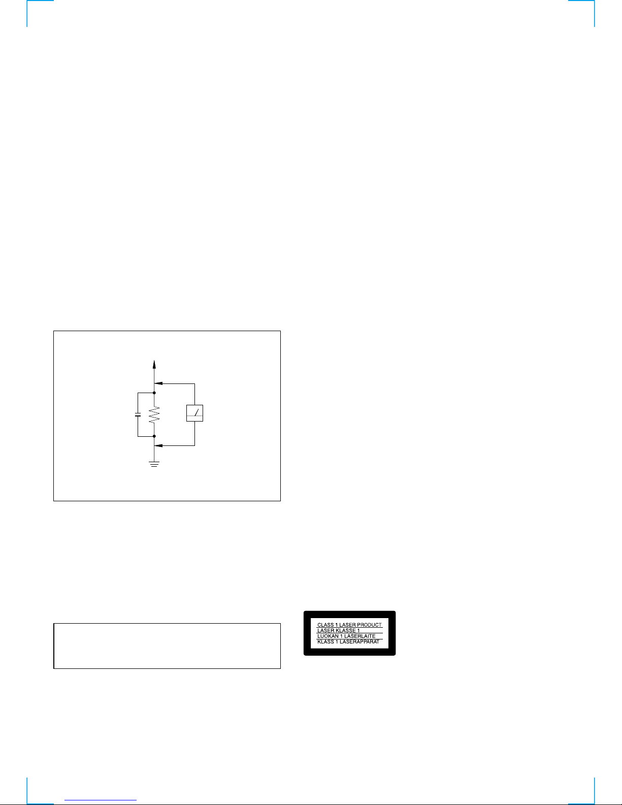
3. Measuring the voltage drop across a resistor by means of a
VOM or battery-operated AC v oltmeter. The "limit" indication
is 0.75V, so analog meters must have an accurate low v oltage
scale. The Simpson 250 and Sanwa SH-63Trd are examples
of a passive VOM that is suitable. Nearly all battery operated
digital multimeters that have a 2V A C range are suitable. (See
Fig. A)
SAFETY-RELATED COMPONENT WARNING!!
COMPONENTS IDENTIFIED BY MARK 0 OR DOTTED LINE WITH
MARK 0 ON THE SCHEMATIC DIAGRAMS AND IN THE PARTS
LIST ARE CRITICAL TO SAFE OPERATION. REPLACE THESE
COMPONENTS WITH SONY PARTS WHOSE PART NUMBERS
APPEAR AS SHOWN IN THIS MANUAL OR IN SUPPLEMENTS
PUBLISHED BY SONY .
ATTENTION AU COMPOSANT AYANT RAPPORT
À LA SÉCURITÉ!
LES COMPOSANTS IDENTIFÉS P AR UNE MARQUE 0 SUR LES
DIAGRAMMES SCHÉMA TIQUES ET LA LISTE DES PIÈCES SONT
CRITIQUES POUR LA SÉCURITÉ DE FONCTIONNEMENT. NE
REMPLACER CES COMPOSANTS QUE PAR DES PIÈSES SONY
DONT LES NUMÉROS SONT DONNÉS DANS CE MANUEL OU
DANS LES SUPPÉMENTS PUBLIÉS PAR SONY.
T o Exposed Metal
Parts on Set
0.15 µF
1.5 kΩ
AC
Voltmeter
(0.75 V)
Earth Ground
Fig. A. Using an A C v oltmeter to check A C leakage.
CAUTION
Use of controls or adjustments or performance of procedures
other than those specified herein may result in hazardous radiation
exposure.
WARNING!!
WHEN SERVICING, DO NO T APPRO A CH THE LASER EXIT WITH
THE EYE TOO CLOSELY. IN CASE IT IS NECESSARY TO
CONFIRM LASER BEAM EMISSION, BE SURE TO OBSERVE
FROM A DIST ANCE OF MORE THAN 25 cm FR OM THE SURF A CE
OF THE OBJECTIVE LENS ON THE OPTICAL PICK-UP BLOCK.
CAUTION:
The use of optical instrument with this product will increase eye
hazard.

— 3 —
TABLE OF CONTENTS
SERVICE NOTE ····································································· 5
SELF-DIAGNOSIS FUNCTION ········································ 6
1. GENERAL
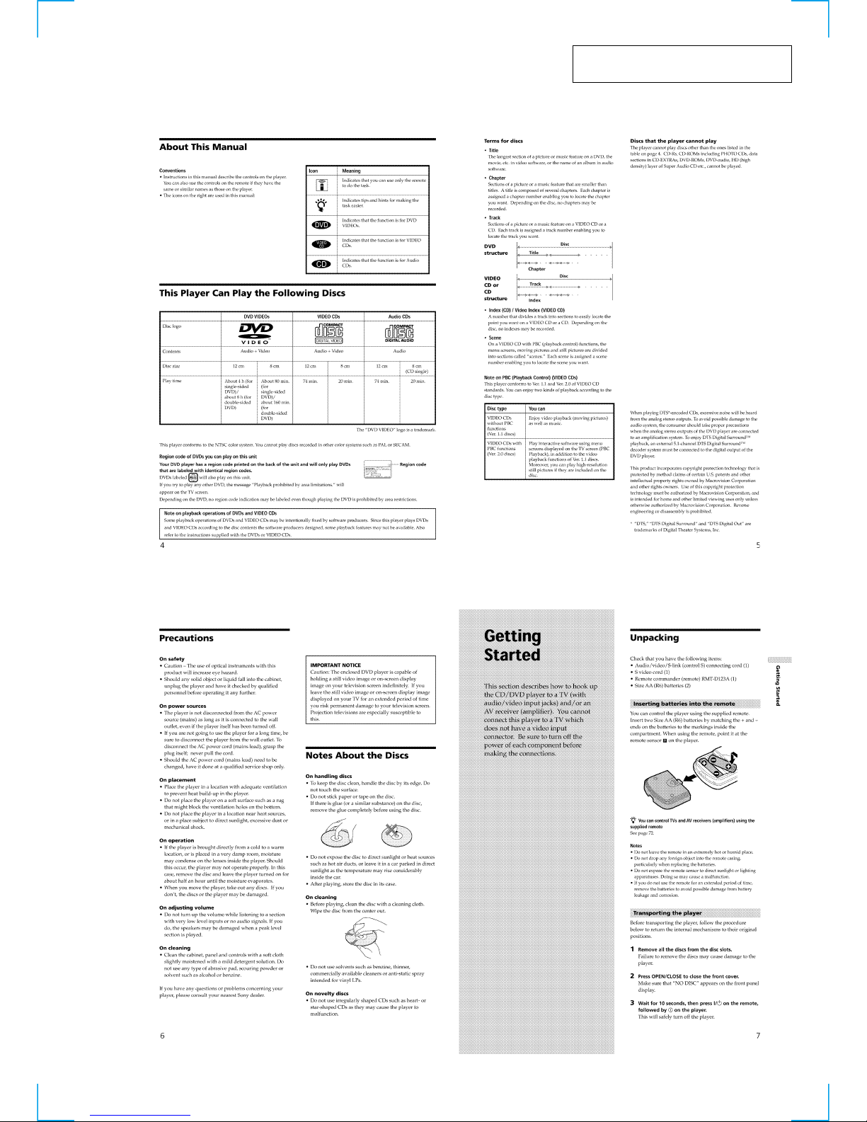
About This Manual ································································1-1
This Player Can Play the Following Discs ····························1-1
Precautions·············································································1-1
Notes About the Discs ···························································1-1
Getting Started···········································································1-1
Unpacking··············································································1-1
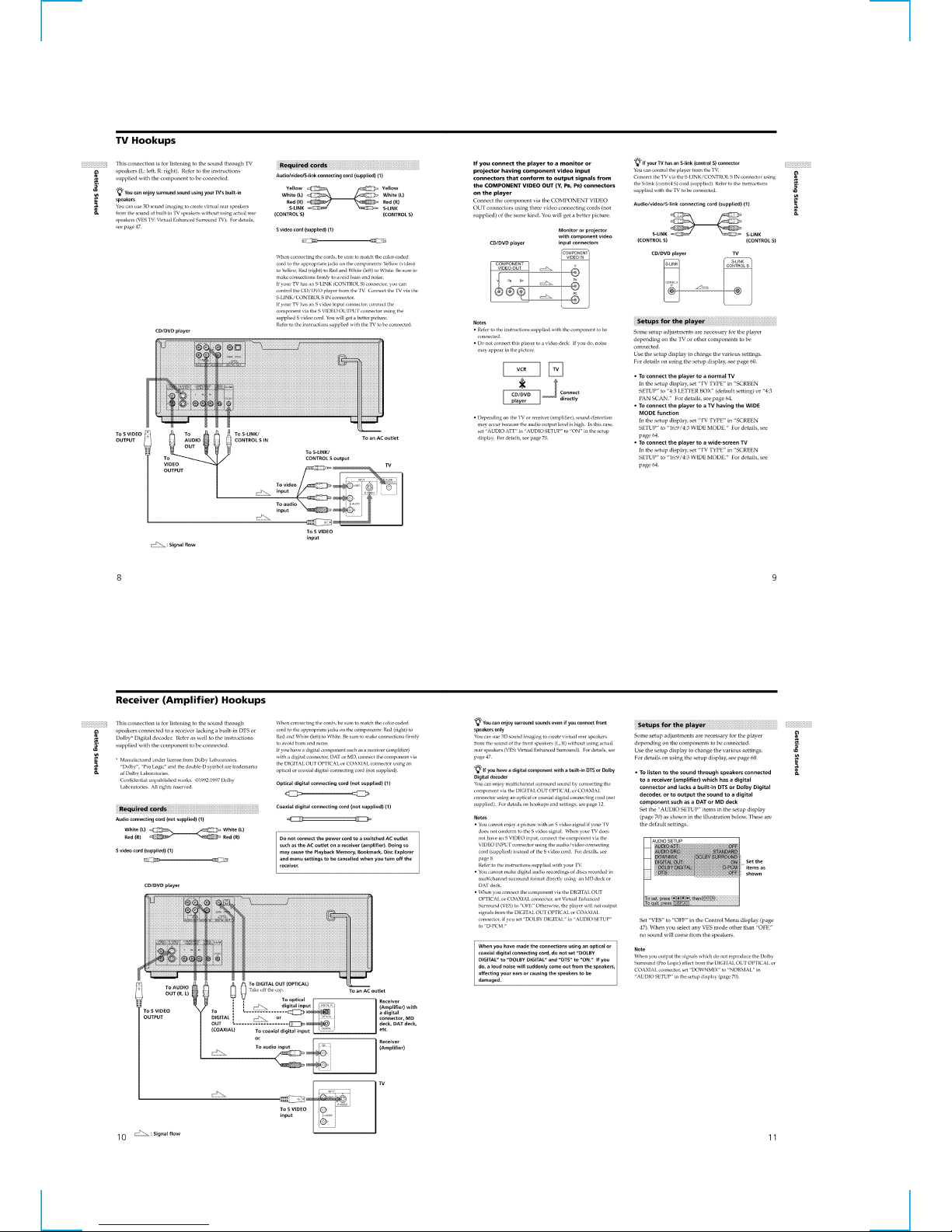
TV Hookups ··········································································1-2
Receiver (Amplifier) Hookups ··············································1-2
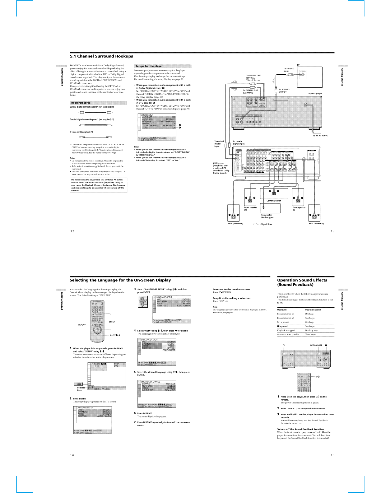
5.1 Channel Surround Hookups·············································1-3
Selecting the Language for the On-Screen Display··············· 1-3
Operation Sound Effects (Sound Feedback)··························1-3
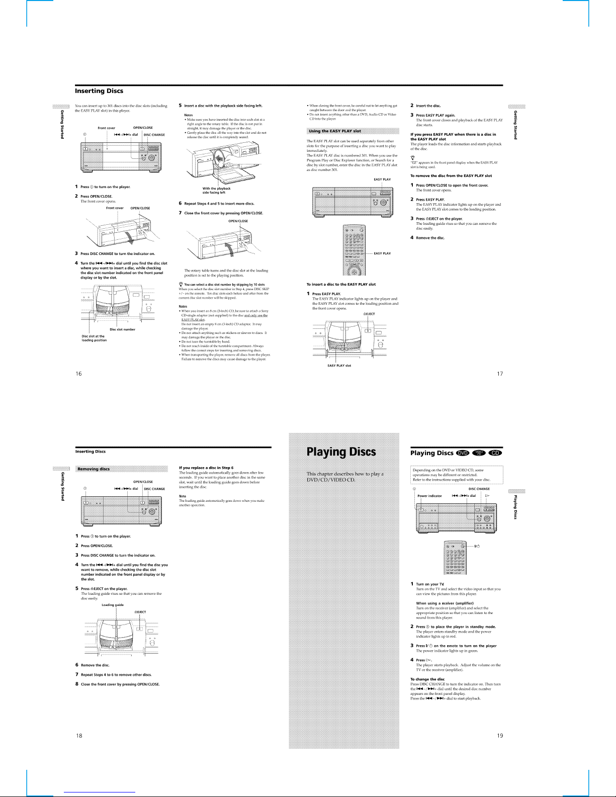
Inserting Discs ·······································································1-4
Playing Discs ·············································································1-4
Playing Discs ·········································································1-4
Playing Side B (FLIP) ···························································1-5
Playing at Various Speeds/Frame by Frame ··························1-5
Resuming Playback from the Point Where You Stopped
the Disc (Resume Play) ······················································1-5
Using the DVD ’s Menu ························································1-6
Playing VIDEO CDs with PBC Functions (PBC Playback)····1-6
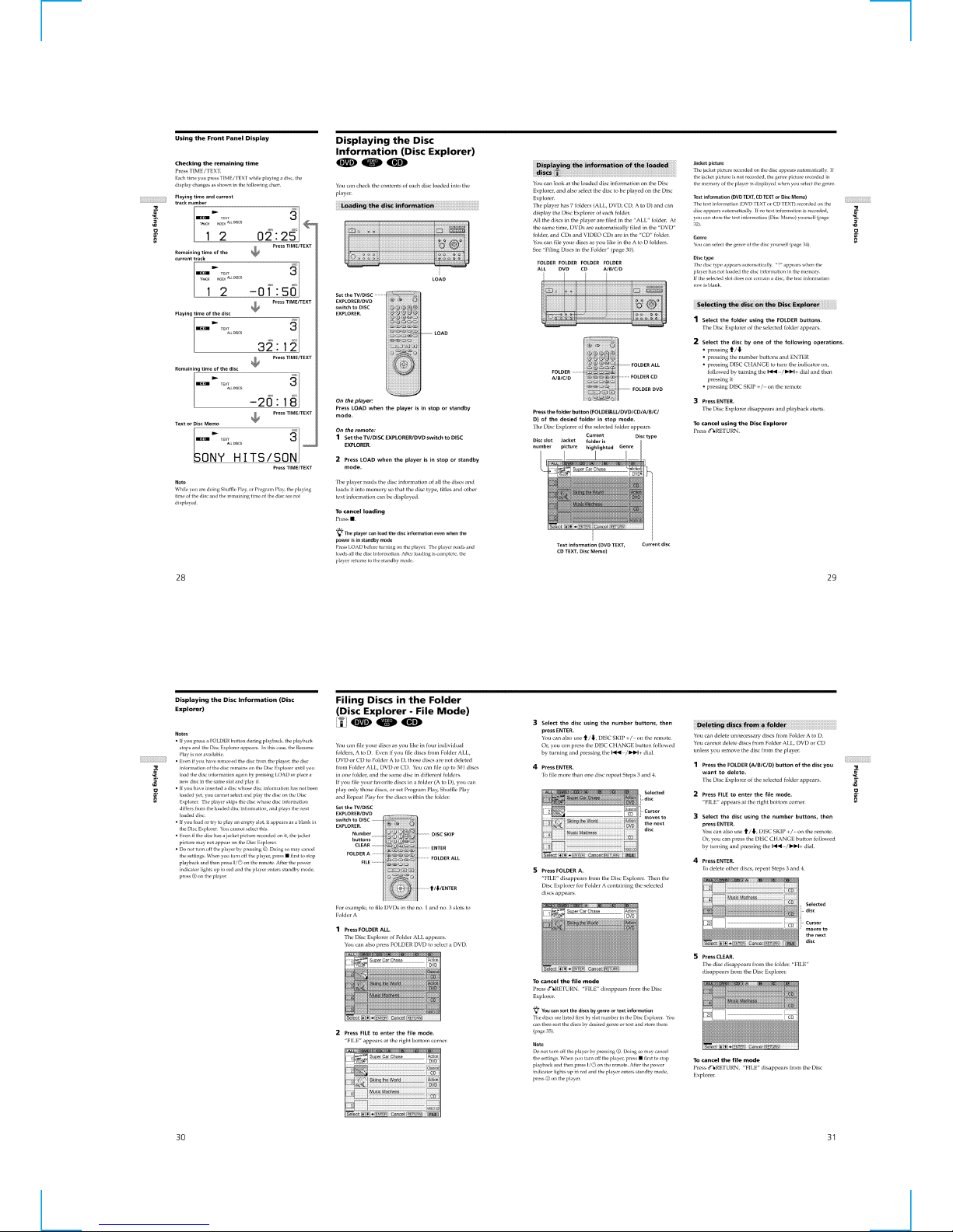
Using the Front Panel Display ···············································1-6
Displaying the Disc Information (Disc Explorer) ·················1-7
Filing Discs in the Folder (Disc Explorer - File Mode)·········1-7
Labeling Discs and Folders (Disc Explorer - Edit Mode) ·····1-8
Sorting Discs (Disc Explorer - Sort Mode) ··························· 1-8
Using Various Functions with the Control Menu ······················1-9
Using the Control Menu Display ···········································1-9
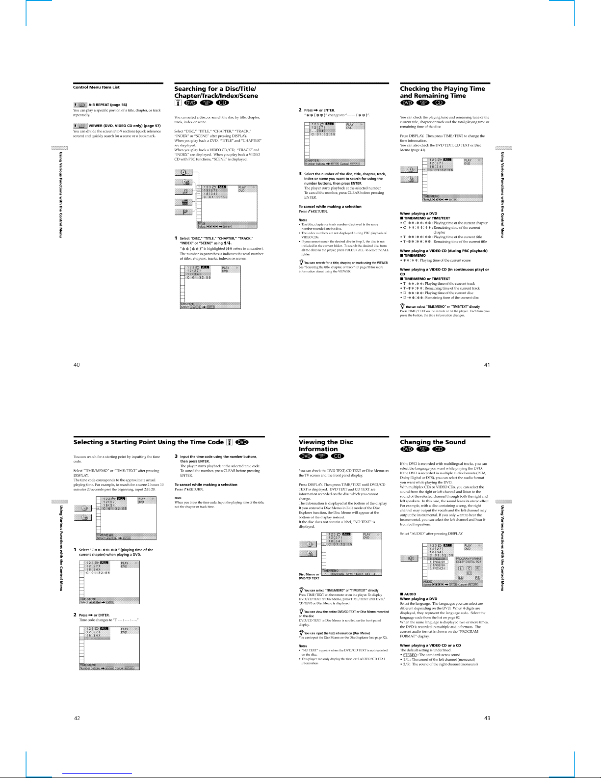
Control Menu Item List ·························································1-9
Searching for a Disc/Title/Chapter/Track/Index/Scene ······· 1-10
Checking the Playing Time and Remaining Time ···············1-10
Selecting a Starting Point Using the Time Code ·················1-10
Viewing the Disc Information·············································· 1-10
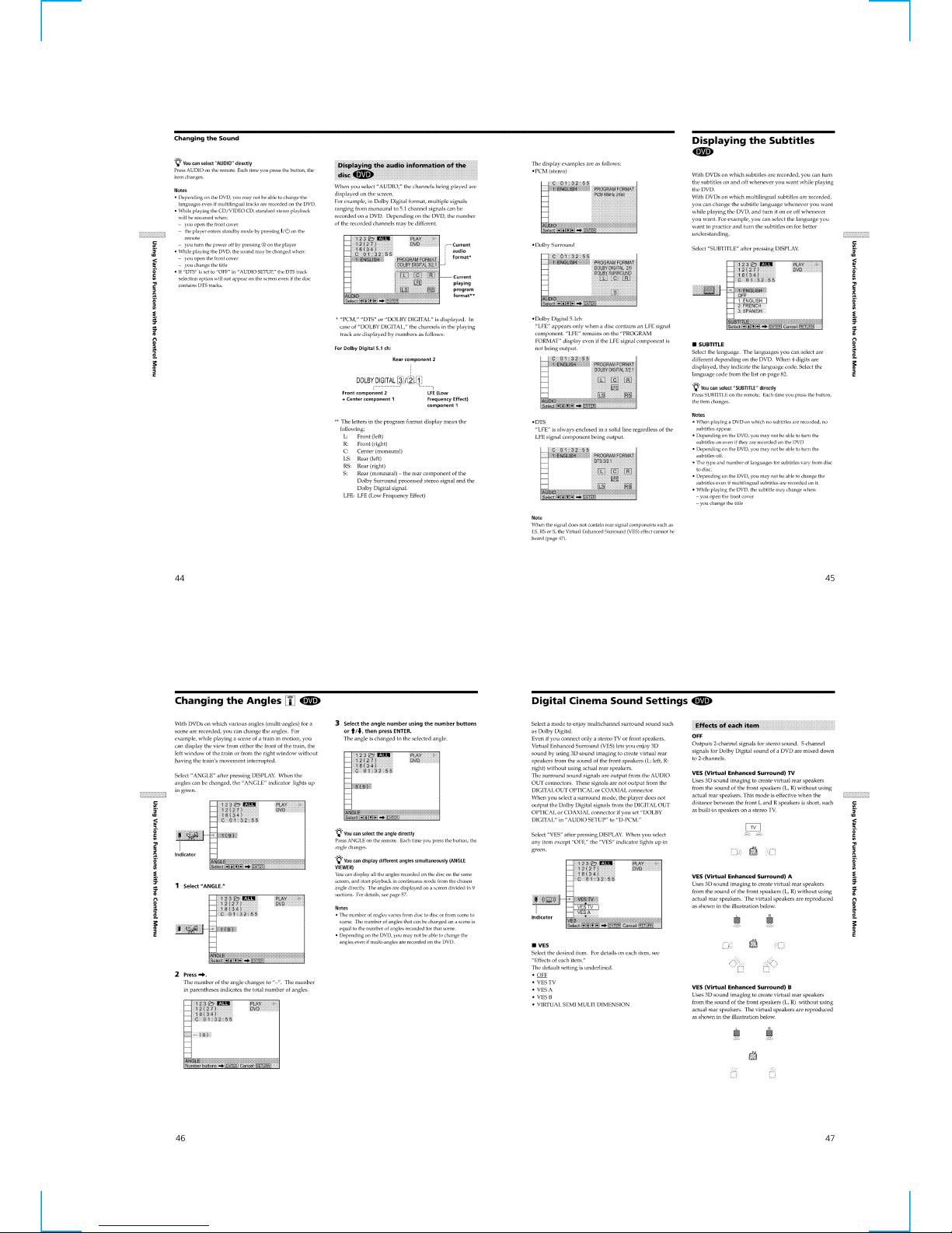
Changing the Sound·····························································1-10
Displaying the Subtitles ······················································· 1-11
Changing the Angles····························································1-11
Digital Cinema Sound Settings············································1-11
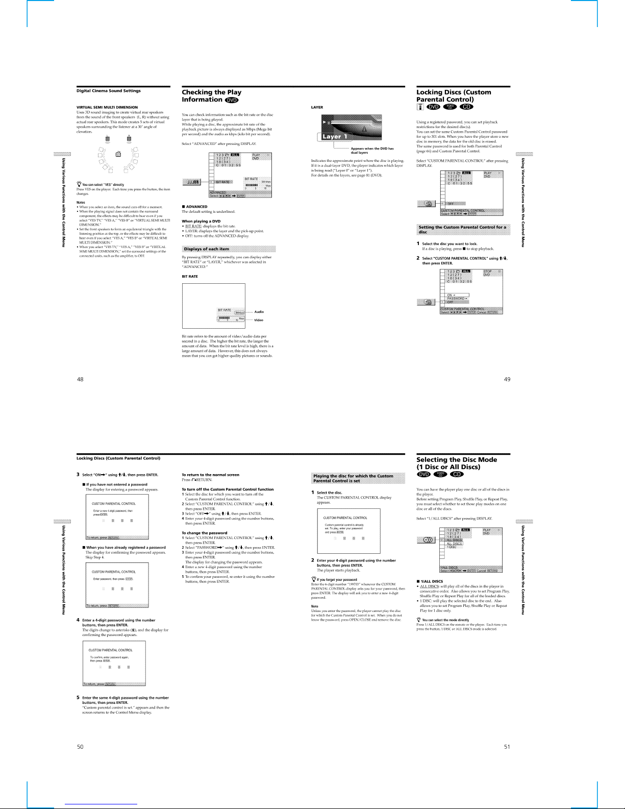
Checking the Play Information ············································1-12
Locking Discs (Custom Parental Control)···························1-12
Selecting the Disc Mode (1 Disc or All Discs)····················1-12
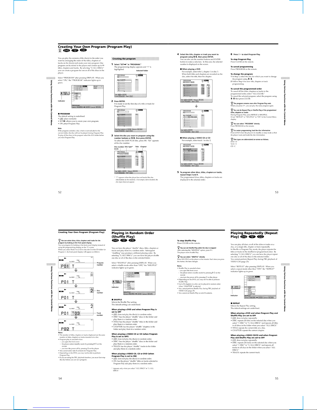
Creating Your Own Program (Program Play)······················1-13
Playing in Random Order (Shuffle Play)·····························1-13
Playing Repeatedly (Repeat Play) ·······································1-13
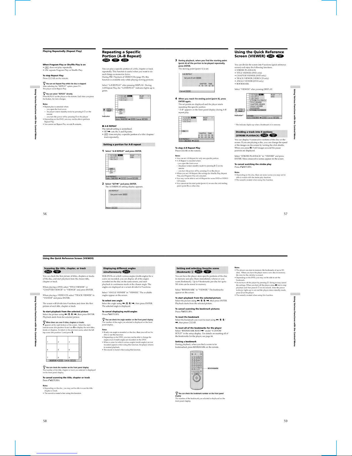
Repeating a Specific Portion (A – B Repeat) ······················1-14
Using the Quick Reference Screen (VIEWER)···················1-14
Settings and Adjustments ························································1-15
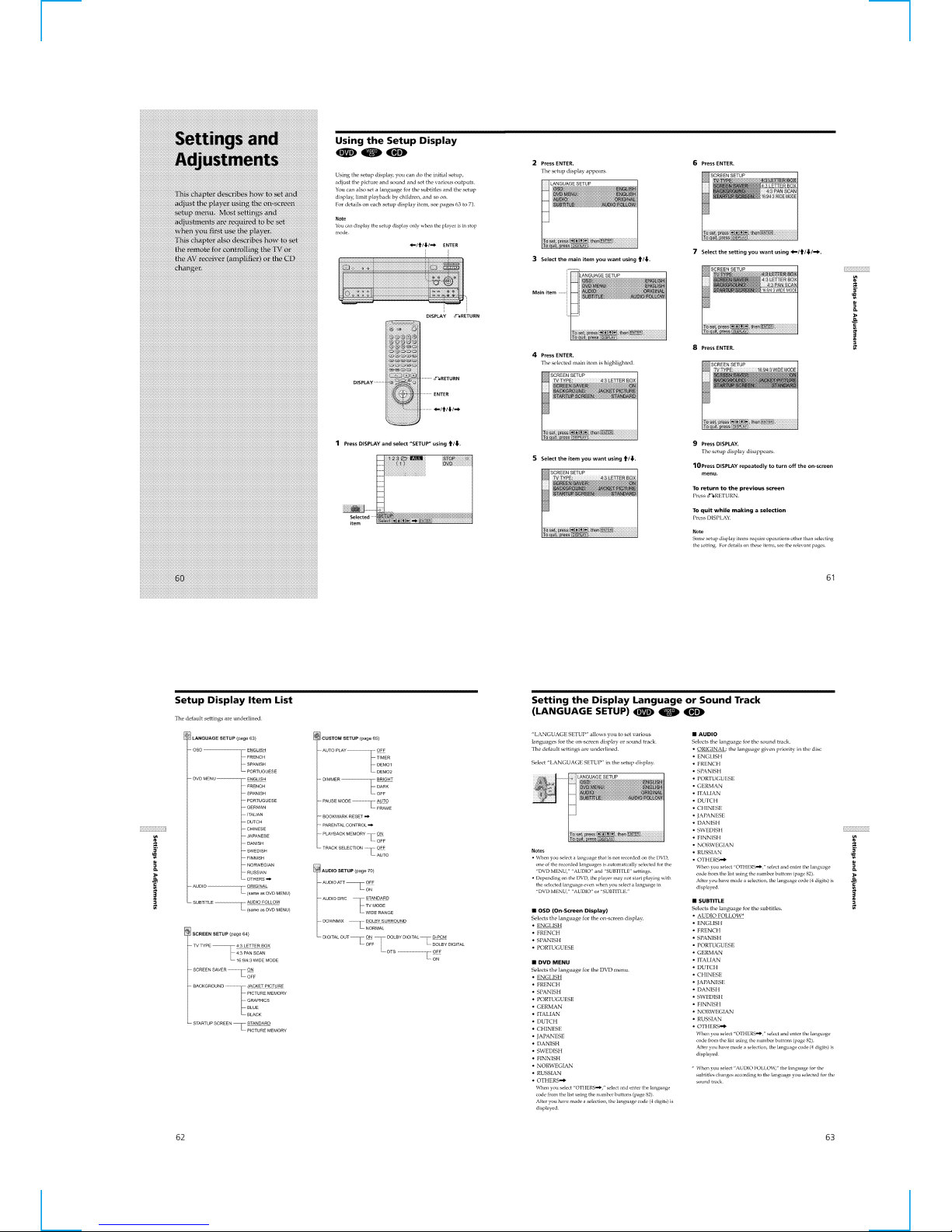
Using the Setup Display ······················································ 1-15
Setup Display Item List ·······················································1-15
Setting the Display Language or Sound Track
(LANGUAGE SETUP) ····················································1-15
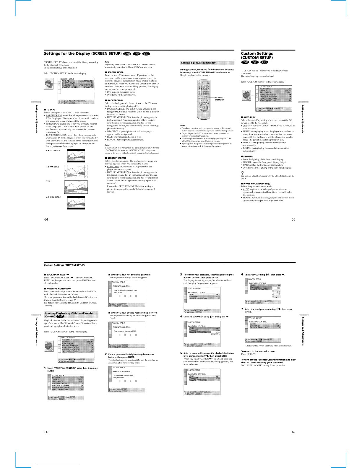
Settings for the Display (SCREEN SETUP) ·······················1-16
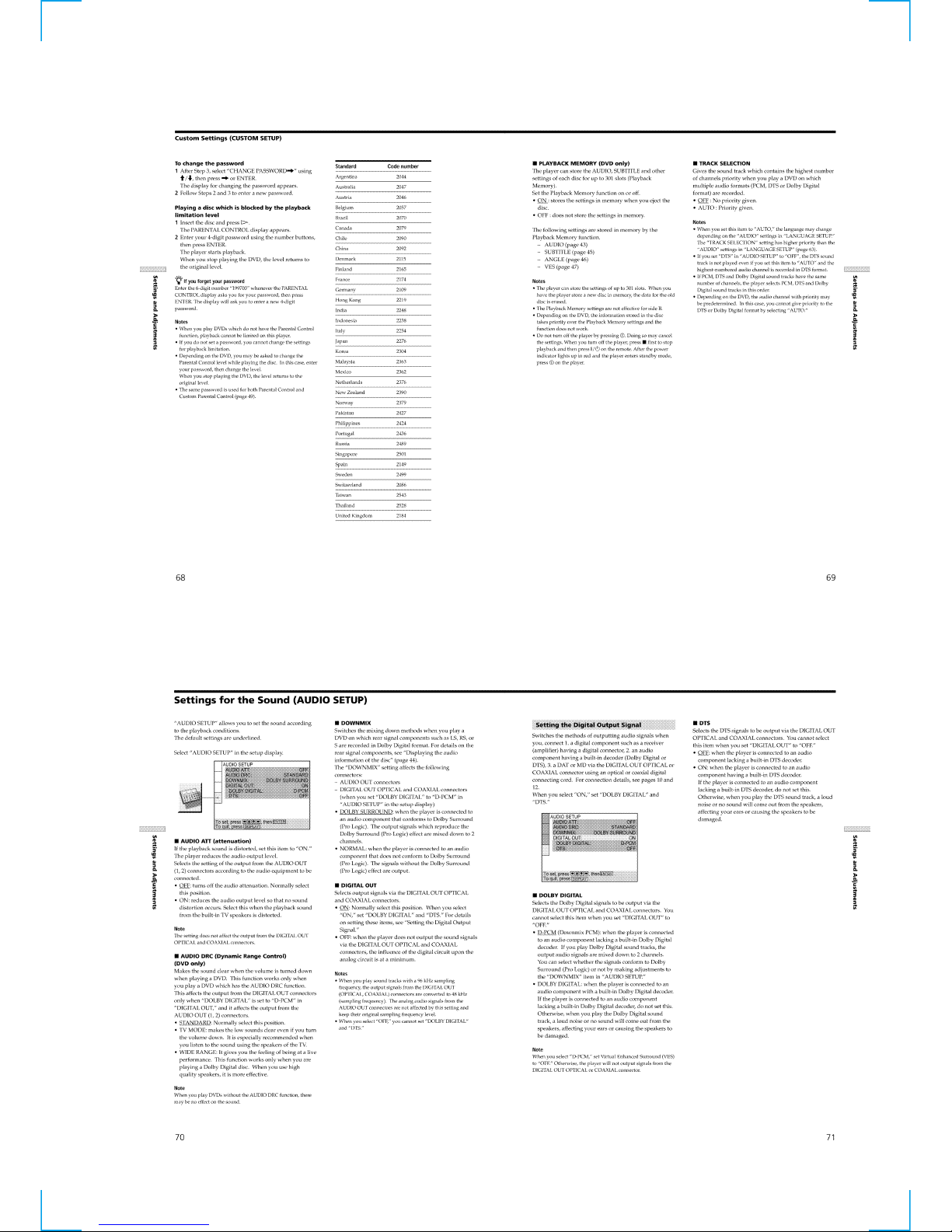
Custom Settings (CUSTOM SETUP) ·································1-16
Settings for the Sound (AUDIO SETUP) ····························1-17
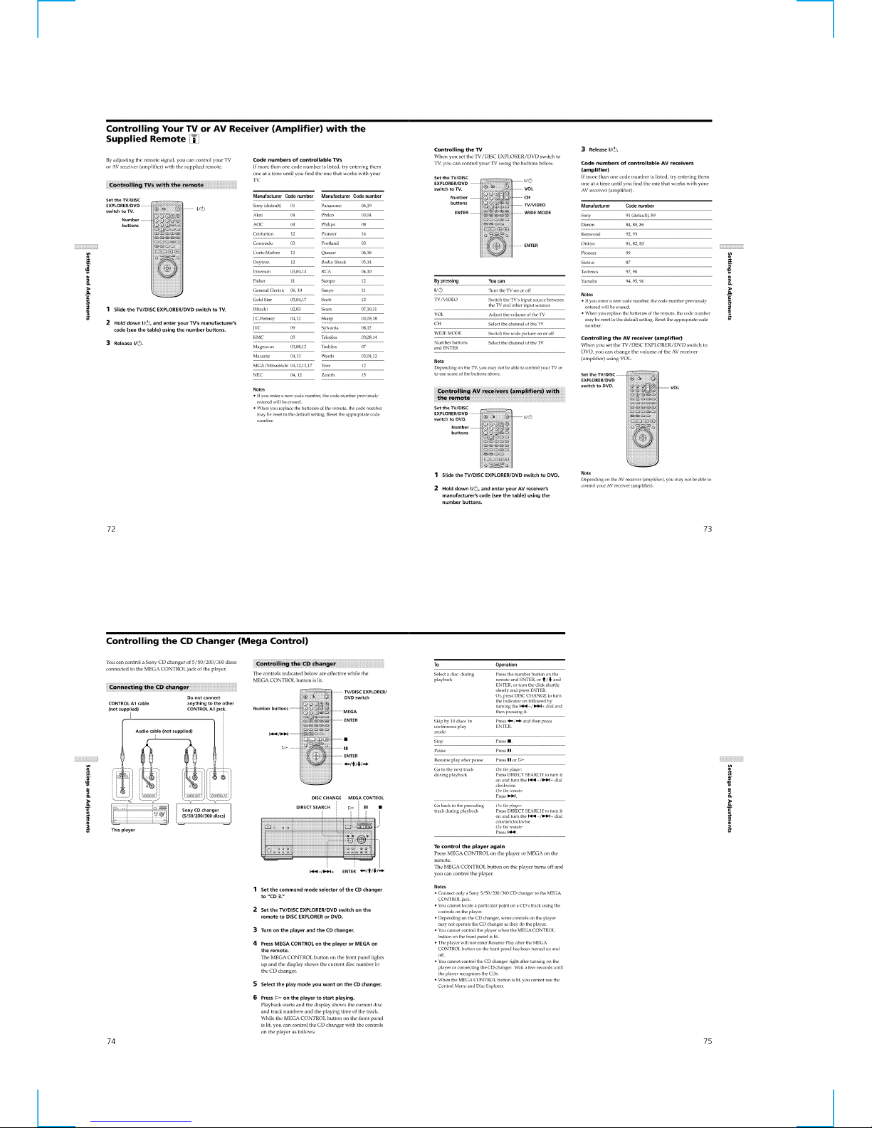
Controlling Your TV or AV Receiver (Amplifier) with the
Supplied Remote······························································ 1-18
Controlling the CD Changer (Mega Control) ······················1-18
Additional Information ····························································1-19
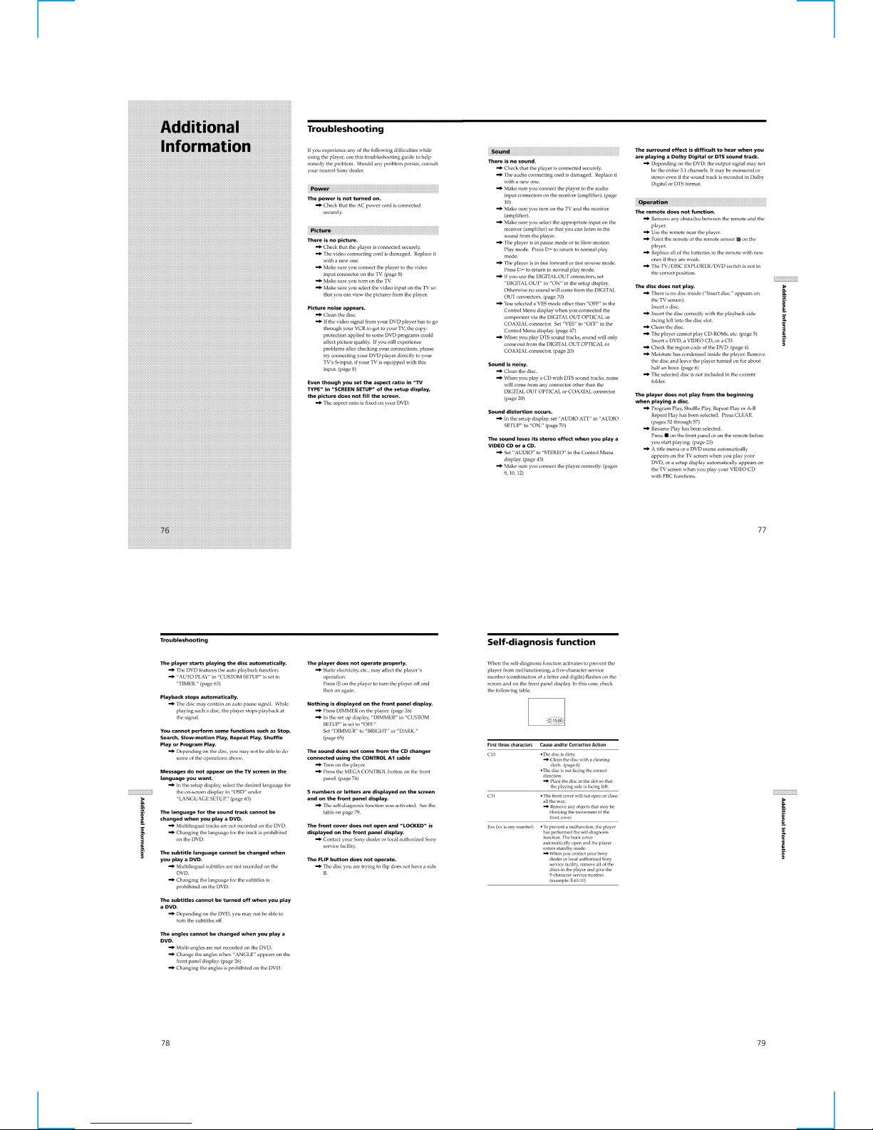
Troubleshooting ···································································1-19
Self-diagnosis function ························································1-19
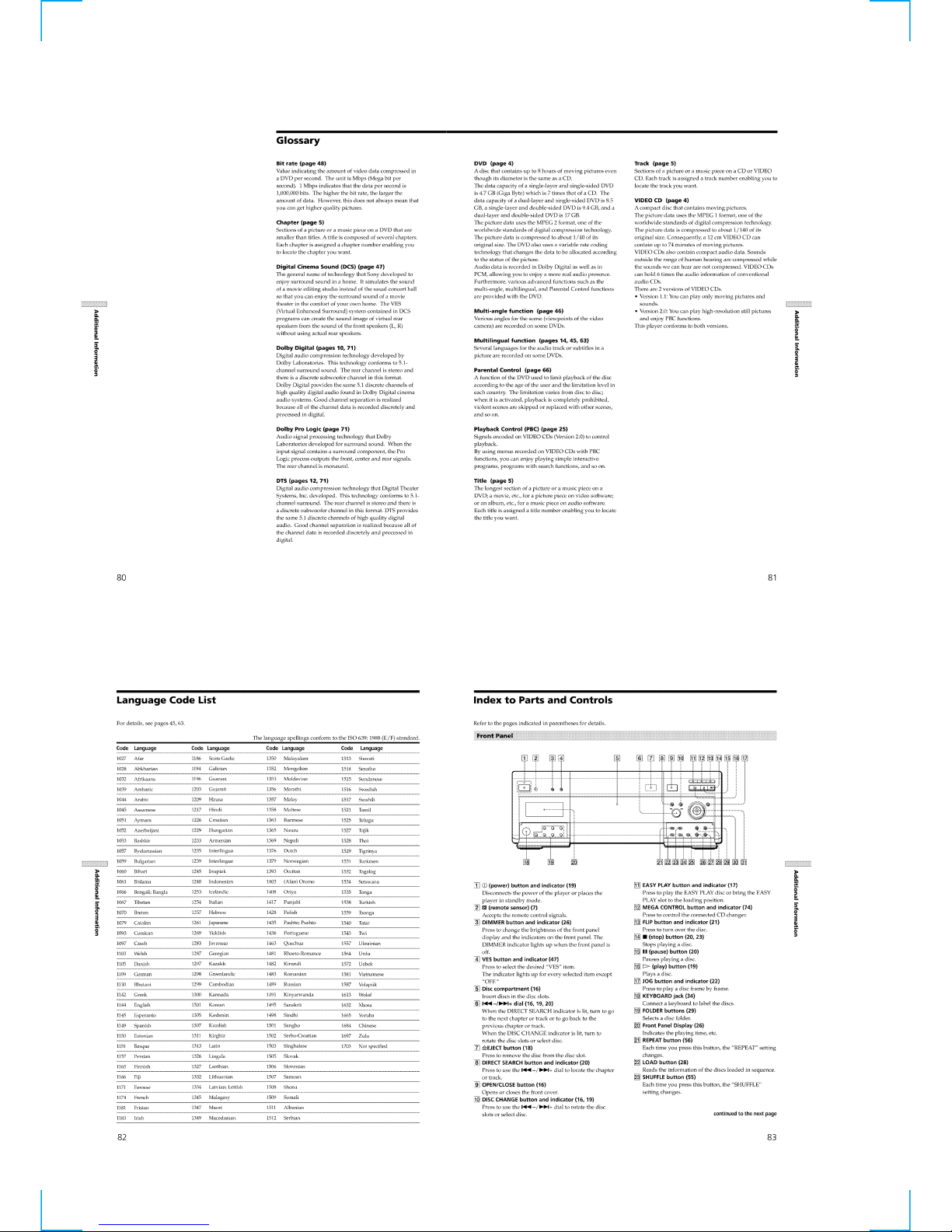
Glossary ···············································································1-20
Language Code List ····························································· 1-20
Index to Parts and Controls··················································1-20
2. DISASSEMBLY
2-1. OVERALL ······································································ 2-1
2-2. FRONT PANEL-1 ···························································2-1
2-3. FRONT PANEL-2 ···························································2-2
2-4. AI-20, MB-94 BOARDS·················································2-2
2-5. JACK PLATE, CV-34 BOARD ·······································2-3
2-6. POWER BLOCK, R PANEL ··········································2-3
2-7. TURN T ABLE ASSEMBLY···········································2-4
2-8. BASE UNIT SECTION ·················································· 2-4
2-9. MECHANICAL CHASSIS SECTION ···························2-5
2-10. T DRIVING ASSEMBLY ···············································2-5
2-11. INTERNAL VIEWS························································2-6
2-12. CIRCUIT BOARDS LOCATION ···································2-7
3. BLOCK DIAGRAMS
3-1. OVERALL BLOCK DIAGRAM ····································3-1
3-2. RF/SERVO BLOCK DIAGRAM···································· 3-3
3-3. SIGNAL PROCESS BLOCK DIAGRAM ······················3-5
3-4. SYSTEM CONTROL BLOCK DIAGRAM ···················3-7
3-5. VIDEO EURO BLOCK DIAGRAM ······························3-9
3-6. AUDIO BLOCK DIAGRAM ········································3-11
3-7. INTERFACE CONTROL BLOCK DIAGRAM (1/2) ··3-13
3-8. INTERFACE CONTROL BLOCK DIAGRAM (2/2) ··3-15
3-9. POWER BLOCK DIAGRAM ·······································3-17
4. PRINTED WIRING BOARDS AND
SCHEMATIC DIAGRAMS
4-1. FRAME SCHEMATIC DIAGRAM (1/2)······················· 4-1
FRAME SCHEMATIC DIAGRAM (2/2)······················· 4-3
4-2. PRINTED WIRING BOARDS AND
SCHEMATIC DIAGRAMS ············································4-5
• TK-59 (RF/SERVO)
PRINTED WIRING BOARD ·························4-7
• TK-59 (RF/SERVO)
SCHEMATIC DIAGRAM ······························4-9
• MB-94 (ARP, AV DECODER, 16M SDRAM, VGA,
SERVO CONTROL, CONNECTOR, SYSTEM
CONTROL, 32M FLASH, PLL, FGA-C, AUDIO)
PRINTED WIRING BOARD ·······················4-11
• MB-94 (ARP)(1/10)
SCHEMATIC DIAGRAM ····························4-13
• MB-94 (AV DECODER)(2/10)
SCHEMATIC DIAGRAM ····························4-15
• MB-94 (16M SDRAM)(3/10)
SCHEMATIC DIAGRAM ····························4-17
• MB-94 (VGA)(4/10)
SCHEMATIC DIAGRAM ····························4-19
• MB-94 (SERVO CONTROL)(5/10)
SCHEMATIC DIAGRAM ····························4-21
• MB-94 (CONNECTOR)(6/10)
SCHEMATIC DIAGRAM ····························4-23
• MB-94 (SYSTEM CONTROL)(7/10)
SCHEMATIC DIAGRAM ····························4-25
• MB-94 (32M FLASH, PLL)(8/10)
SCHEMATIC DIAGRAM ····························4-27
• MB-94 (FGA-C)(9/10)
SCHEMATIC DIAGRAM ····························4-29
• MB-94 (AUDIO)(10/10)
SCHEMATIC DIAGRAM ····························4-31
• AI-20 (VIDEO)(1/3)
SCHEMATIC DIAGRAM ····························4-33
• AI-20 (2.6CH AUDIO)(2/3)
SCHEMATIC DIAGRAM ····························4-35
• AI-20 (INTERFACE)(3/3)
SCHEMATIC DIAGRAM ····························4-37
• AI-20 (VIDEO, 2.6CH AUDIO, INTERFACE)
PRINTED WIRING BOARD ·······················4-39

— 4 —
• FR-173 (IF COM, KEY BOARD JACK, FLD),
LE-30 (DOLBY LED)
PRINTED WIRING BOARDS ·····················4-41
• FR-173 (IF COM)(1/2), LE-30 (DOLBY LED)
SCHEMATIC DIAGRAMS·························· 4-43
• FR-173 (KEY BOARD JACK, FLD)(2/2)
SCHEMATIC DIAGRAM ····························4-45
• CH-98 (AUDIO)
PRINTED WIRING BOARD ·······················4-47
• CH-98 (AUDIO)
SCHEMATIC DIAGRAM ····························4-49
• ER-12 (EURO AV)
PRINTED WIRING BOARD ·······················4-51
• ER-12 (EURO AV)
SCHEMATIC DIAGRAM ····························4-53
• CV-34 (VIDEO OUT)
PRINTED WIRING BOARD ·······················4-55
• CV-34 (VIDEO OUT)
SCHEMATIC DIAGRAM ····························4-57
• CK-97 (MOTOR DRIVER)
PRINTED WIRING BOARD ·······················4-59
• CK-97 (MOTOR DRIVER)
SCHEMATIC DIAGRAM ····························4-61
• TS-151 (T SENSOR), DM-96 (DOOR MOTOR)
PRINTED WIRING BOARDS ·····················4-63
• TM-128 (TRAY MOTOR), DA-29 (DR SENSOR),
LC-70 (LOADING/CAM MOTOR)
PRINTED WIRING BOARDS ·····················4-65
• TS-151 (T SENSOR), DM-96 (DOOR MOTOR),
TM-128 (TRAY MOTOR), DA-29 (DR SENSOR),
LC-70 (LOADING/CAM MOTOR)
SCHEMATIC DIAGRAMS·························· 4-67
• LS-55 (LD SENSOR)
PRINTED WIRING BOARD ·······················4-69
• LT-37 (LED), LT-38 (LED), CS-57 (CK SENSOR)
PRINTED WIRING BOARDS ·····················4-71
• LS-55 (LD SENSOR), LT-37 (LED), LT-38 (LED),
CS-57 (CK SENSOR)
SCHEMATIC DIAGRAMS·························· 4-73
• FL-115 (DISPLAY CONTROL),
SW-345 (EJECT SW)
PRINTED WIRING BOARDS ·····················4-75
• FL-115 (DISPLAY CONTROL),
SW-345 (EJECT SW)
SCHEMATIC DIAGRAMS·························· 4-77
• POWER BLOCK (MPW1241)(US, CND MODEL),
POWER BLOCK (MPW1141)(AEP, UK MODEL)
PRINTED WIRING BOARDS ·····················4-79
• POWER BLOCK (MPW1241)(US, CND MODEL),
POWER BLOCK (MPW1141)(AEP, UK MODEL)
SCHEMATIC DIAGRAMS·························· 4-81
5. IC PIN FUNCTION DESCRIPTION
5-1. SYSTEM CONTROL PIN FUNCTION
MB91108PFV-G-BND (MB-94 BOARD IC102)··········· 5-1
6. TEST MODE
6-1. GENERAL DESCRIPTION ···········································6-1
6-2. STARTING TEST MODE···············································6-1
6-3. SYSCON DIAGNOSIS···················································6-1
6-4. DRIVE AUT O ADJUSTMENT ······································6-5
6-5. DRIVE MANUAL OPERATION ···································6-7
6-6. MECHA AGING ···························································6-11
6-7. EMERGENCY HISTORY ············································6-11
6-8. VERSION INFORMATION ·········································6-12
6-9. VIDEO LEVEL ADJUSTMENT ··································6-12
6-10. IF CON SELF DIAGNOSTIC FUNCTION ·················6-13
7. ELECTRICAL ADJUSTMENT
7-1. POWER SUPPLY ADJUSTMENT································· 7-1
7-2. ADJUSTMENT OF VIDEO SYSTEM···························7-2
7-3. CHECK OF AUDIO SYSTEM ·······································7-3
8. REPAIR PARTS LIST
8-1. EXPLODED VIEWS ······················································8-1
8-1-1.OVERALL SECTION·····················································8-1
8-1-2.FRONT PANEL SECTION············································· 8-2
8-1-3.CHASSIS SECTION·······················································8-3
8-1-4.MECHANISM SECTION···············································8-4
8-2. ELECTRICAL PARTS LIST ··········································8-5
— 5 —
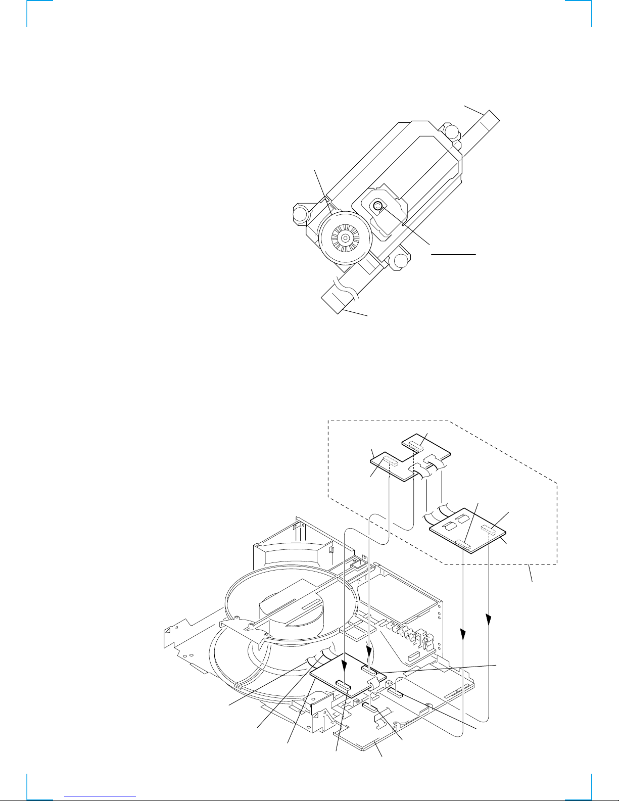
From TK-59 board (CN002)
(Flexible board)
Flexible board
Ojective lens
From TK-59 board (CN001)
(Flexible board)
Turntable (spindle motor)
SERVICE NOTE
1. REPLACING OPTICAL PICK-UP
1-1. Handling
A red laser diode for DVD requires more attention to static electricity
than general infrared laser diodes for CD.
Because its durability to static electricity is far weaker than that of
infrared laser diodes, always use an earth band when handling the
optical pick-up block as service parts.
1-2. When the turntable is removed, be sure to
perform the sensor adjustment.
Refer to “8. 300 CHG Mecha Con Menu 2” of Section “6. TEST
MODE” (page 6-10) for the adjustment procedure.
1-3. How to service MB-94 board
Establish the equipment setup as shown in illustration using the jig
(J-6090-102-A) referring to Section “2-1. OVERALL” of DISASSEMBLY.
Jig (J-6090-102-A)
AI-20 board
Ch-jig1 board
Ch-jig2 board
CN201
CN102
CN502
CN702
CN103
CN203
CN204
CN104
MB-94 board
(from TK-59 board (CN004))
(from TK-59 board (CN003))
— 6 —
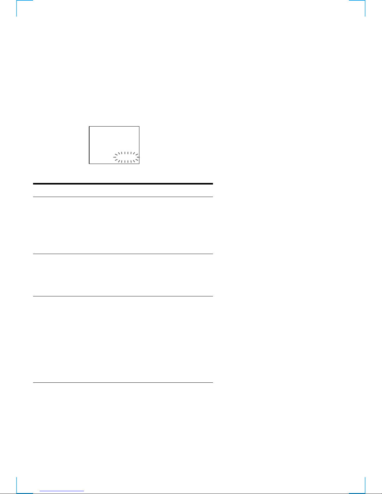
SELF-DIAGNOSIS FUNCTION
Self-diagnosis function
When the self-diagnosis function activates to prevent the
player from malfunctioning, a five-character service
number (combination of a letter and digits) flashes on the
screen and on the front panel display. In this case, check
the following table.
First three characters
C13
C31
Exx (xx is any number)
Cause and/or Corrective Action
•The disc is dirty.
Clean the disc with a cleaning
cloth. (page 6)
•The disc is not facing the correct
direction.
Place the disc in the slot so that
the playing side is facing left.
•The front cover will not open or close
all the way.
Remove any objects that may be
blocking the movement of the
front cover.
•To prevent a malfunction, the player
has performed the self-diagnosis
function. The front cover
automatically open and the player
enters standby mode.
When you contact your Sony
dealer or local authorized Sony
service facility, remove all of the
discs in the player and give the
5-character service number.
(example: E:61:10)
C:13:00
1-1
SECTION 1
GENERAL
DVP-CX860/CX870D
This section is extracted from instruction
manual. (DVP-CX860 model)
1-2
1-3
1-4

1-5

1-6
1-7

1-8

1-9
1-10
1-11
1-12
1-13
1-14
1-15
1-16
1-17
1-18
1-19
1-20

1-21

1-22E
MEMO
2-1
DVP-CX860/CX870D
SECTION 2
DISASSEMBLY
NOTE: Follow the disassembly procedure in the numerical order given.
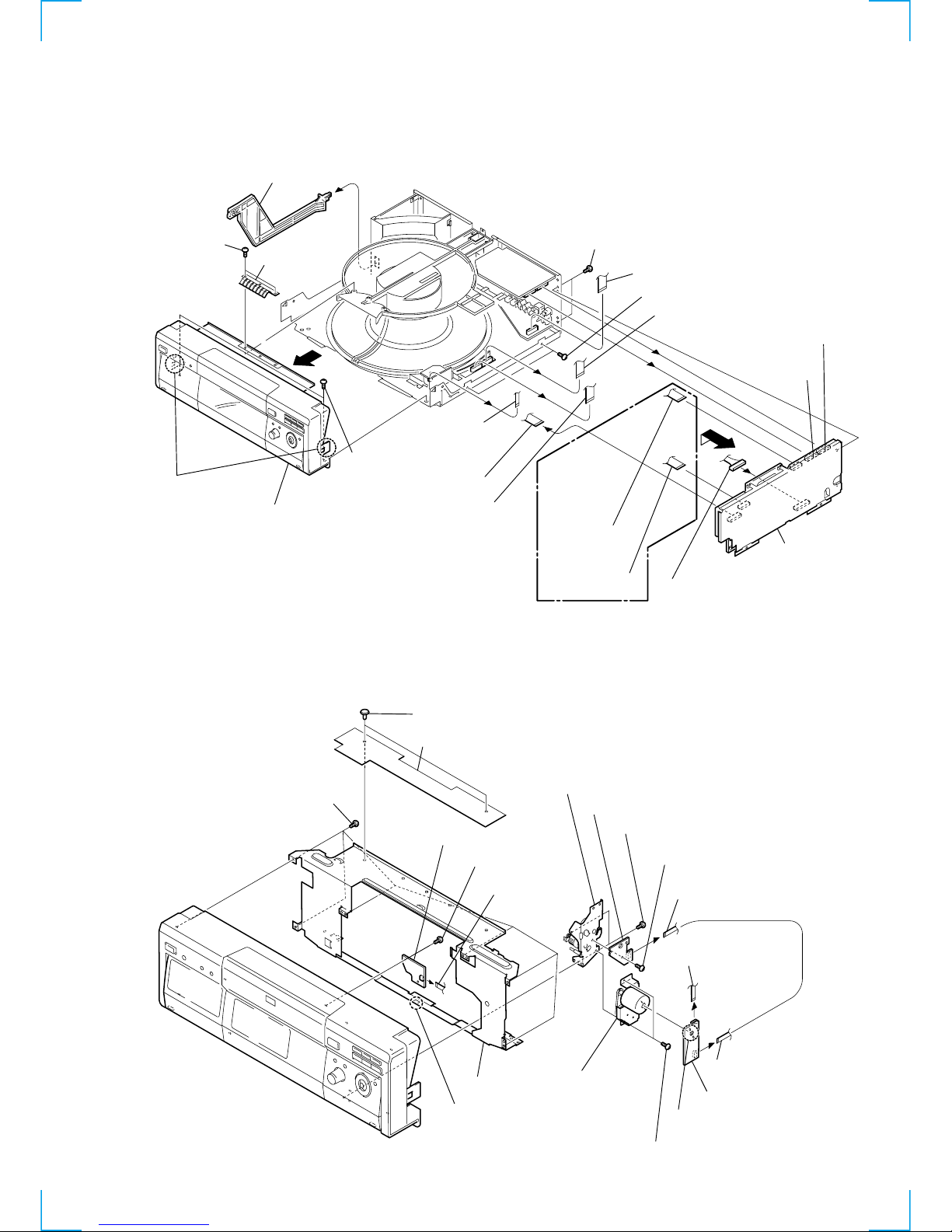
2-1. OVERALL
1
T wo screws
(+BV 3
×
10)
3
Two screws (+BV 3 × 6)
qs
Two screws (+BV 3 × 10)
qd
Two screws (+BV 3 × 10)
ql
Flat cable (CN501, 154p)
qg
Flat cable (CN005, 15p)
qj
Board to board connector (15p)
qf
Board to board
connector (15p)
qk
Flat cable
(CN004, 17p)
7
Flat cable
(CN204, 11p)
8
Flat cable
(CN103, 15p)
wa
AI board
section
5
Flat cable (CN308, 23p)
6
Flat cable
(CN103, 6p)
q;
Front panel section
qa
P-SW rod
2
Spring(H),
ground plate
qh
9
4
Two claws
w;
Harness (PA-137) (CN101, 15p)
DVP-CX860
(AEP,UK)
model
2-2. FRONT PANEL-1
qk Screw
(+BVTP
2.6
× 8)
qj Flat cable
(CN301, 3p)
ql SW-345 board
1 Two screws (+BVTP
2.6
× 8)
9 Screws (+BVTP
2.6
× 8)
4 Two screws (+BVTP
2.6
× 8)
qg Flexible cover
qf Two rivets
qh Front chassis
qd Claw
qs Six screws (+BVTP
2.6
× 8)
7 DM-96 board
6 Remove the two solderings.
8 Driving gear
(B) block assy
qa Gear base plate (A) assy
q; DA-29 board
5 Flat cable
(CN501, 154p)
2 Flat cable (CN192, 4p)
3 Flexible flat cable (CN161, 4p)
2-2
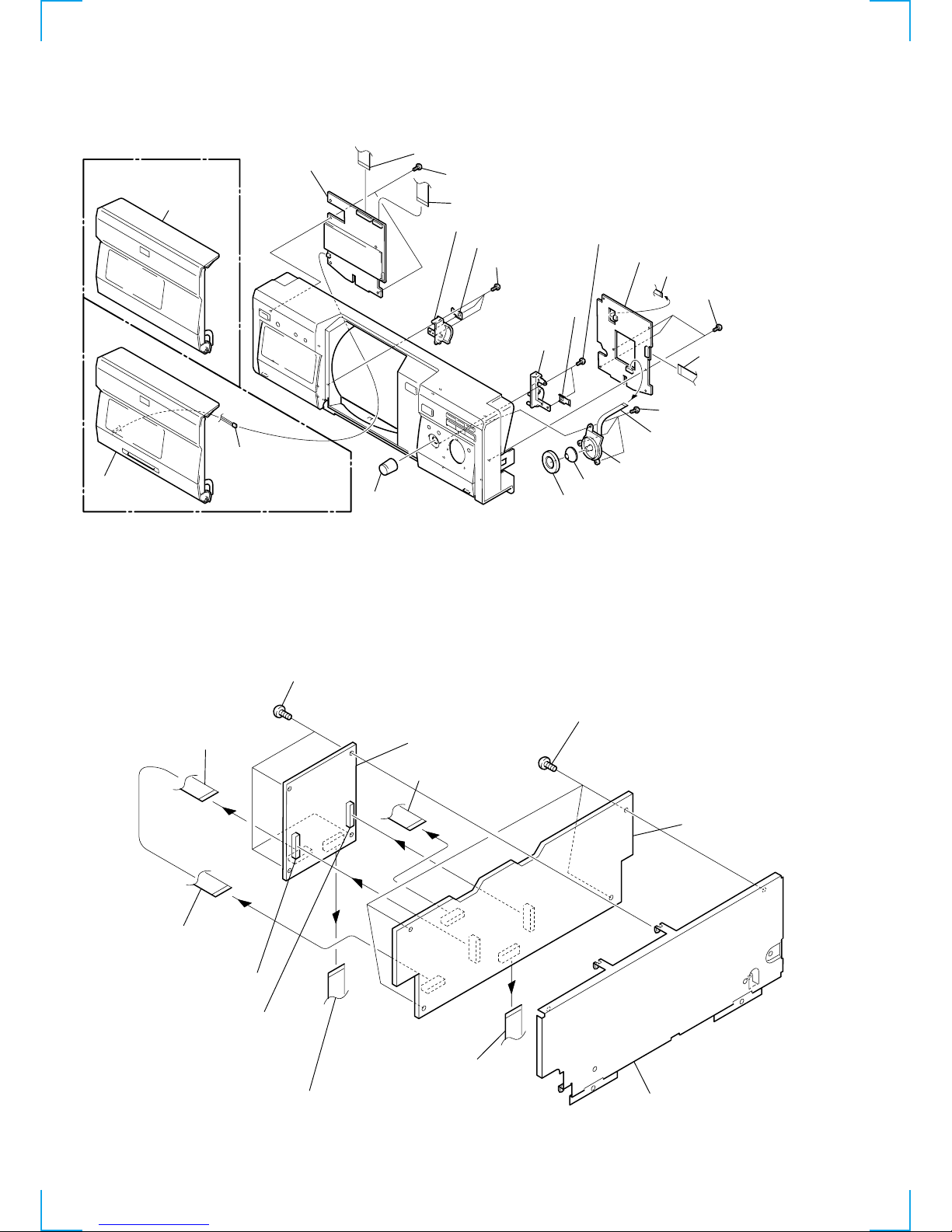
2-3. FRONT PANEL-2
2-4. AI-20, MB-94 BOARDS
qh Three screws
(+BVTP
2.6
× 8)
qk Flap guide (L) assy
w; SP spring
qj SP spring
ql Two screws (+BVTP
2.6
× 8)
wa Flap
frame assy
DVP-CX860 model
qa Two screws (+BVTP
2.6
× 8)
7 Three screws
(+BVTP
2.6
× 8)
4 Three screws
(+BVTP
2.6
× 8)
qs Flat cable (CN102, 23p)
qd Flat cable (CN101, 15p)
3 Flat cable (CN405, 3p)
5 Flat cable
(CN403, 15p)
6 FL-115 board
q; Rotary encoder
9 Cursor stick
8 Shuttle ring
1 ACS/AMS knob
qg FR-173
board
2 Rotary encoder
(CN404, 9p)
DVP-CX870D
model
ws Door
block assy
ws Door
block assy
qf Door block assy
(CN103, 2p)
q; Four screws
(+BV 3 ×
6
)
3 Four screws
(+BV 3 ×
6
)
1 Flat cable
(CN801, 18p)
8 Flat cable
(CN104, 15p)
2 Flat cable (CN802, 15p)
2 Flat cable (CN307, 16p)
7 Flat cable
(CN301, 18p)
4 Board to board connector
(CN502, 18p)
5 Board to board connector
(CN702, 18p)
qs AI Bracket assy
qa AI-20 board
6 MB-94 board
 Loading...