

Sony PCV-RX680G, PCV-RX650, PCV-RX690G, PCV-RX600E, PCV-RX600N Service Manual
...
PCV-RX6
__
Series
SERVICE MANUAL
For American Area
US Model
Ver. 4-2002F
Canadian Model
Revision History
Lineup: PCV-RX640 PCV-RX671
PCV-RX650 PCV-RX672
PCV-RX660 PCV-RX681
PCV-RX670 PCV-RX682
PCV-RX680G PCV-RX651
PCV-RX690G PCV-RX641
PCV-RX600E
PCV-RX600N
Specifications
Model-name PCV-RX690G PCV-RX680G PCV-RX670 PCV-RX660 PCV-RX650 PCV-RX681 PCV-RX682
CPU
M/B (EE) (AN) (AN) (AN) (AN) (AN) (AN)
Memory std/max 512MB/1024MB 512MB/1024MB 512MB/1024MB 512MB/1024MB 512MB/1024MB 1024MB/1024MB 1024MB/1024MB
HDD Bay 1 120GB 120GB 80GB 80GB 80GB 120GB 120GB
Opt.Device Upper DVD-RW DVD-RW DVD-RW DVD-ROM DVD-ROM DVD-RW DVD-RW
Expansion Card
(Top) Slot4 (AGP) VGA Card VGA Card VGA Card VGA Card VGA Card VGA Card VGA Card
Slot3 (PCI) ---- Slot2 (PCI) MPEG ( ENX-17 ) MPEG ( ENX-17 ) - - (Bottom) Slot1 (PCI) Modem Modem Modem Modem Modem Modem Modem
MemoryStick aaaaaaa
OS Win XP Home Win XP Home Win XP Home Win XP Home Win XP Home Win XP Home Win XP Home
Slot 1 512MB 512MB 512MB 256MB/512MB 256MB / 512MB 512MB 512MB
Slot 2 (256MB CTO) None None 256MB/None 256MB / None 512MB 512MB
Bay 2 -----
Lower DVD-ROM CD-ROM CD-ROM CD-RW CD-RW CD-ROM DVD-ROM
P4 2.2GHz
P4 2.0AGHz
P4 1.8GHz P4 1.8GHz P4 1.6GHz P4 2.2GHz P4 2.2GHz
-
-
-
-
-
-
S400
Model-name PCV-RX671 PCV-RX672 PCV-RX640 PCV-RX600E PCV-RX600N PCV-RX651
CPU P4 2.0AGHz P4 2.0AGHz
M/B (AN) (AN) (BI) (EE) (AN) (AN)
Memory std/max 512MB/1024MB 512MB/1024MB 256MB/512MB 1024MB max 1024MB max
HDD Bay 1 120GB 120GB 60GB 60GB / 80GB / 120GB 60GB / 80GB / 120GB 80GB
Opt.Device Upper DVD-RW DVD-RW DVD-ROM DVD-RW / DVD-ROM DVD-RW / DVD-ROM DVD-ROM
Expansion Card
(Top) Slot4 (AGP) VGA Card VGA Card VGA Card VGA Card VGA Card VGA Card
Slot3 (PCI) - - Slot2 (PCI) (Bottom) Slot1 (PCI) Modem Modem Modem Modem Modem Modem
MemoryStick aa✕ aaa
OS Win XP Home Win XP Home Win XP Home Win XP Home
Slot 1 512MB 512MB 256MB 256MB / 512MB 256MB / 512MB 256MB 256MB
Slot 2 - -
Bay 2 - None / 120GB None / 120GB -
Lower CD-ROM DVD-ROM CD-RW DVD-ROM / CD-RW DVD-ROM / CD-RW CD-RW
--
-
- None / MPEG ( ENX-17 ) None / MPEG ( ENX-17 )
-
-
Cel 1.3GHz
- None / 256MB / 512MB None / 256MB / 512MB -
P4 1.6GHz / 1.8GHz / 2GHz /
2.2GHz(NW)
CTO Model CTO Model
P4 1.6GHz / 1.8GHz / 2GHz /
2.2GHz(NW)
Win XP Home / Win XP Professional
P4 1.7GHz
256MB/1024MB
-
-
Win XP Home
PCV-RX641
Cel 1.3GHz
(BI)
256MB/512MB
-
40GB
-
CD-RW
-
VGA Card
-
-
Modem
×
Win XP Home
PERSONAL COMPUTER VAIO
9-874-333-04
Information in this document is subject to change without notice.
CAUTION
Sony, VAIO and CLIE are trademarks or registered trademarks of
Sony. Microsoft, Windows, Windows Media, Outlook, Bookshelf
and other Microsoft products are trademarks or registered trademarks
of Microsoft Corporation in the United States and other countries.
The word Bluetooth and the Bluetooth logo are trademarks of
Bluetooth SIG, Inc. AMD, AMD logo, AMD Duron and
combinations thereof , 3DNow!, are trademarks of Advanced Micro
Devices, Inc. Intel Inside logo, Pentium and Celeron are trademarks
or registered trademarks of Intel Corporation.Transmeta, the
Transmeta logo, Crusoe Processor, the Crusoe logo and
combinations thereof are trademarks of Transmeta Corporation in
the USA and other countries. Graffiti, HotSync, PalmModem, and
Palm OS are resistered trademarks, and the Hotsync logo and Palm
are trademarks of Palm, Inc. or its subsidiaries. (M) and Motrola
are trademarks of Motrora, Inc. Other Motrola products and services
with (R) mark like Dragomball are the trademarks of Motrola, Inc.
All other names of systems, products and services in this manual
are trademarks or registered trademarks of their respective o wners.
In this manual, the (TM) or (R) mark are not specified.
Danger of explosion if battery is incorrectly replaced.
Replace only with the same or equivalent type
recommended by the manufacturer.
Dispose of used batteries according
to the manufacturer’s instructions.
Confidential
PCV-RX6__Series (AM)
– 2 –

TABLE OF CONTENTS
1. OPERATION
........................................................... 1-1
2. DISASSEMBLY
2-1. Flow Chart................................................................ 2-1
2-2. Top Panel Section .................................................... 2-2
2-3. Left Panel Section.................................................... 2-2
2-4. DVD-ROM, DVD-RW, CD-RW, CD-ROM............ 2-3
2-5. Switching Power ...................................................... 2-4
2-6. HDD ......................................................................... 2-5
2-7. PCI Slot Panel .......................................................... 2-5
2-8. VGA Card ................................................................ 2-6
2-9. Mounted PWB ENX-15........................................... 2-6
2-10. Modem Card ............................................................ 2-7
2-11. Panel Ass’y (Upper) (For 2 Bay)............................. 2-7
2-12. Panel Ass’y (Lower) (U).......................................... 2-8
2-13. Right Panel............................................................... 2-8
2-14. CNX-138 Board ....................................................... 2-9
2-15. CNX-137 Board ....................................................... 2-9
2-16. SWX-66 Board ........................................................ 2-10
2-17. FDD.......................................................................... 2-10
2-18. CNX-169/IFX-185 Board........................................ 2-11
2-19. Memory .................................................................... 2-12
2-20. CPU .......................................................................... 2-14
CPU Installation....................................................... 2-15
2-21. Mother Board ........................................................... 2-16
3. PROGRAMS FOR SERVICE
3-1. General ..................................................................... 3-1
3-2. PC-Doctor Starting Method..................................... 3-1
3-3. intel815E-B Video Diag Starting Method ............... 3-1
4. SERVICE INFORMATION
4-1. Jumper Setting on Hard Disk Drive ........................ 4-1
5. FRAME HARNESS
5-1. Connector List
1. Mother Board (BI) ................................................... 5-1
2. Mother Board (AN) ................................................. 5-4
3. Mother Board (EE) .................................................. 5-6
5-2. Frame Harness Diagram and Jumper Setting
of Mother Board ...................................................... 5-9
6. REPAIR PARTS LIST
6-1. Exploded Views and Parts List
(Mother Board (BI) Assy) ....................................... 6-1
6-2. Exploded Views and Parts List
(Mother Board (AN) Assy)...................................... 6-3
6-3. Exploded Views and Parts List
(Mother Board (EE) Assy)....................................... 6-5
6-4. Accessories and Parts List ....................................... 6-8
History of the changes is shown as the “Revision
History” at the end of this data.
– 3 –
Confidential
PCV-RX6__Series (AM)
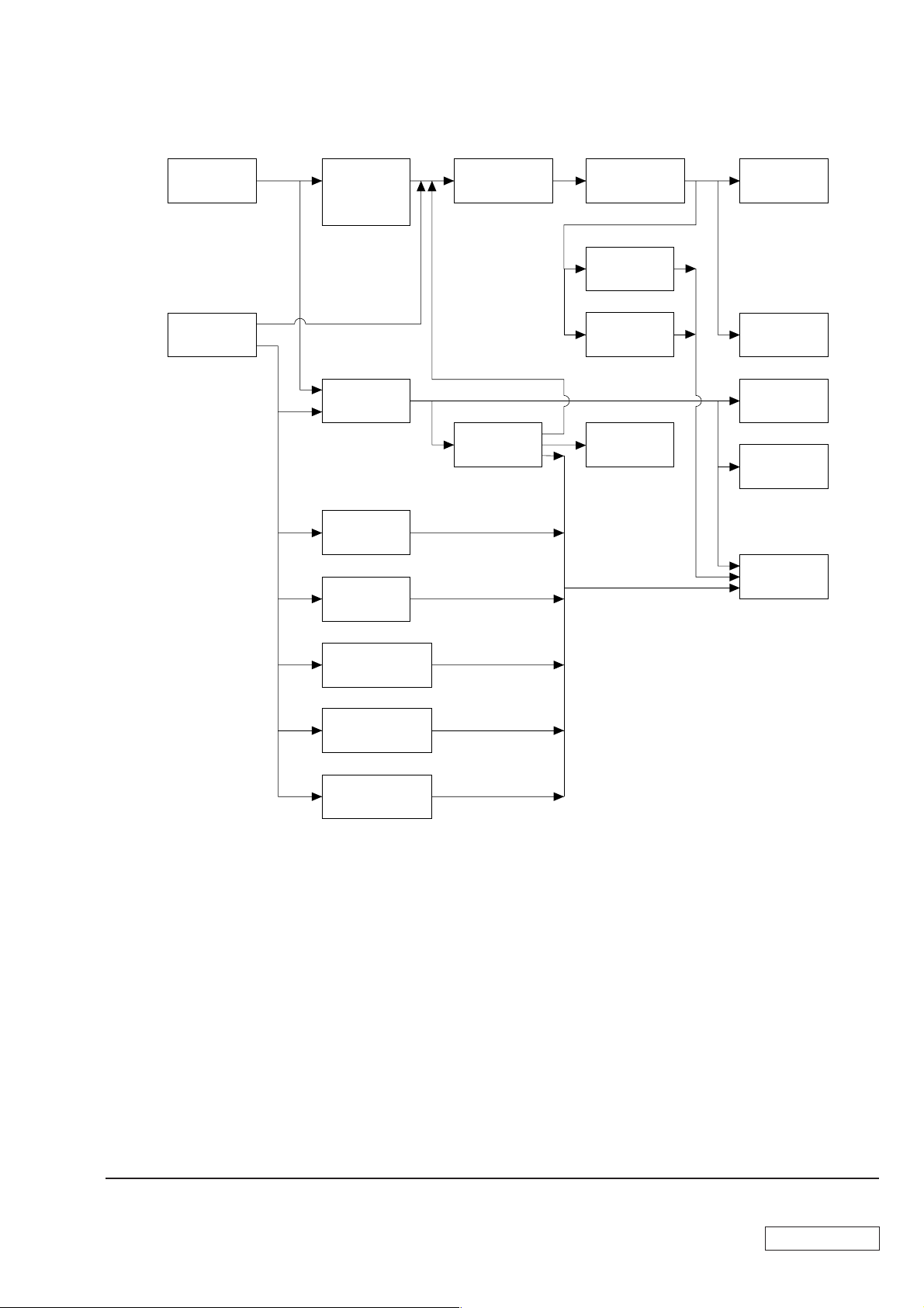
2-1. FLOW CHART
SECTION 2
DISASSEMBLY
TOP PANEL
SECTION
P2-2
LEFT PANEL
SECTION
P2-2
DVD-ROM,
DVD-RW,
CD-RW,
CD-ROM
P2-3
SWITCHING
POWER
P2-4
HDD
P2-5
PCI SLOT
PANEL
P2-5
PANEL ASS’Y
(UPPER)
(FOR 2 BAY)
P2-7
FDD
P2-10
PANEL ASS’Y
(LOWER) (U)
P2-8
CNX-138
BOARD
P2-9
CNX-137
BOARD
P2-9
CNX-169/
IFX-185
BOARD
P2-11
RIGHT
PANEL
P2-8
SWX-66
BOARD
P2-10
MEMORY
P2-12
CPU
P2-14
MOTHER
BOARD
P2-16
VGA CARD
P2-6
MOUNTED PWB
ENX-15
P2-6
MODEM CARD
P2-7
•Ps-s denotes the page concerned.
• HDD has a low resistance to vibration, requiring careful handling.
2-1
Confidential
PCV-RX6__Series (AM)
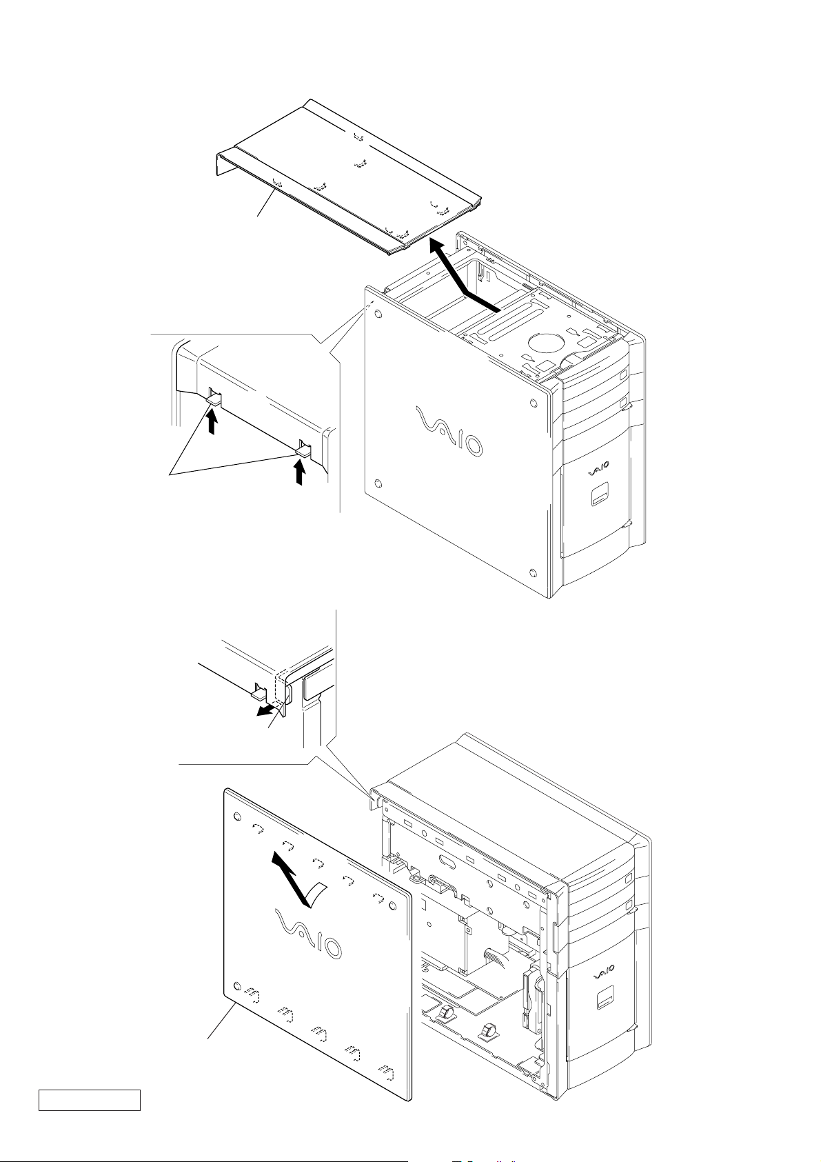
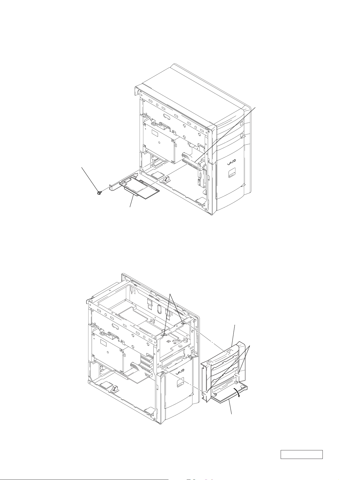
2-2. TOP PANEL SECTION
2
Remove the top panel section
in the direction of arrow
1
two claws
A
.
A
2-3. LEFT PANEL SECTION
1
Pull thelever.
A
2
Remove the left panel section
in the direction of arrow
Confidential
PCV-RX6__Series (AM)
A
.
2-2
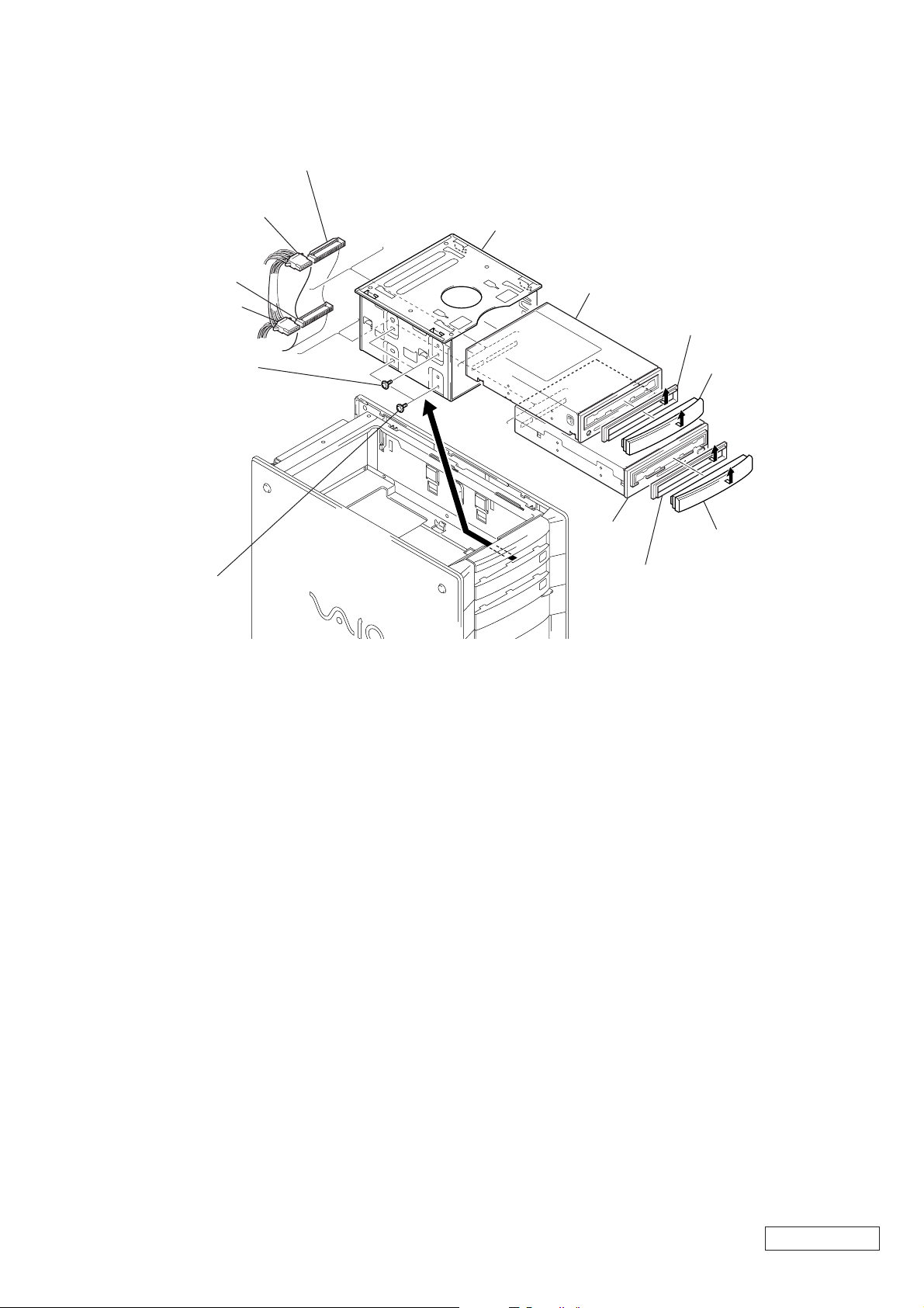
2-4. DVD-ROM, DVD-RW, CD-RW, CD-ROM
2
harness (IDE CD/DVD)
1
power connector
4
harness (IDE CD/DVD)
3
power connector
6
two screws
(PWH3
×
5)
5
Remove the CD holder ass’y
in the direction of arrow
7
DVD-ROM
DVD-RW
A
.
9
Remove the drive adaptor
in the direction of arrow
8
Remove the escutcheon
in the direction of arrow
C
C
.
B
.
0
two screws
(PWH3
A
qa
CD-RW
CD-ROM
qd
Remove the drive adaptor
×
5)
in the direction of arrow
B
E
D
Remove the escutcheon
qs
in the direction of arrow
E
.
D
.
2-3
Confidential
PCV-RX6__Series (AM)
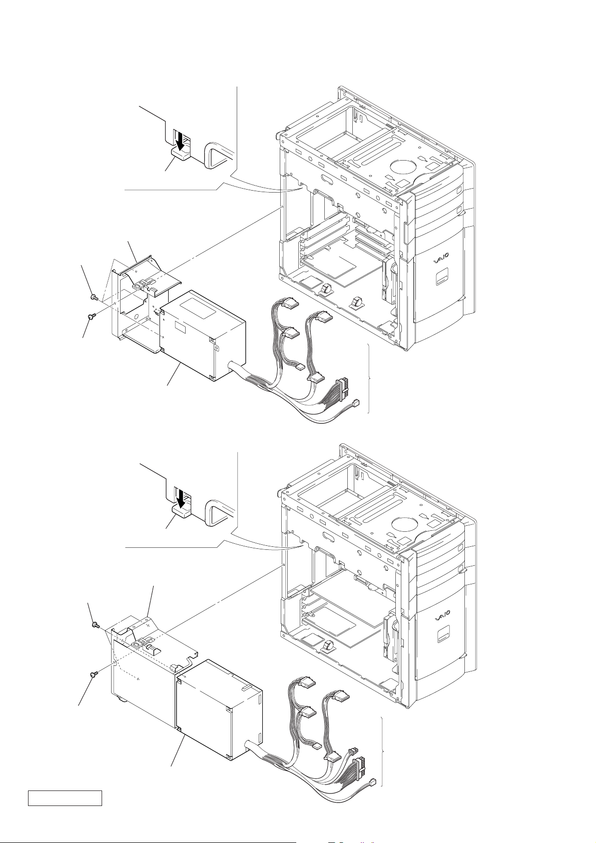
2-5. SWITCHING POWER
(1-468-417-72)
2
Push the lever.
3
bracket power
supply ass’y
5
three screws
(No.6-32UNC)
1
screw
(No.6-32UNC)
(1-468-601-14)
5
three screws
(No.6-32UNC)
6
switching power
2
Push the lever
3
bracket power supply ass’y
4
Disconnect respective
power connectors on the
mother board, DVD-ROM,
CD-RW, FDD and HDD.
1
screw
(No.6-32UNC)
Confidential
PCV-RX6__Series (AM)
6
switching power
2-4
4
Disconnect respective
power connectors on the
mother board, DVD-ROM,
DVD-RW, CD-RW, CD-ROM,
FDD and HDD.
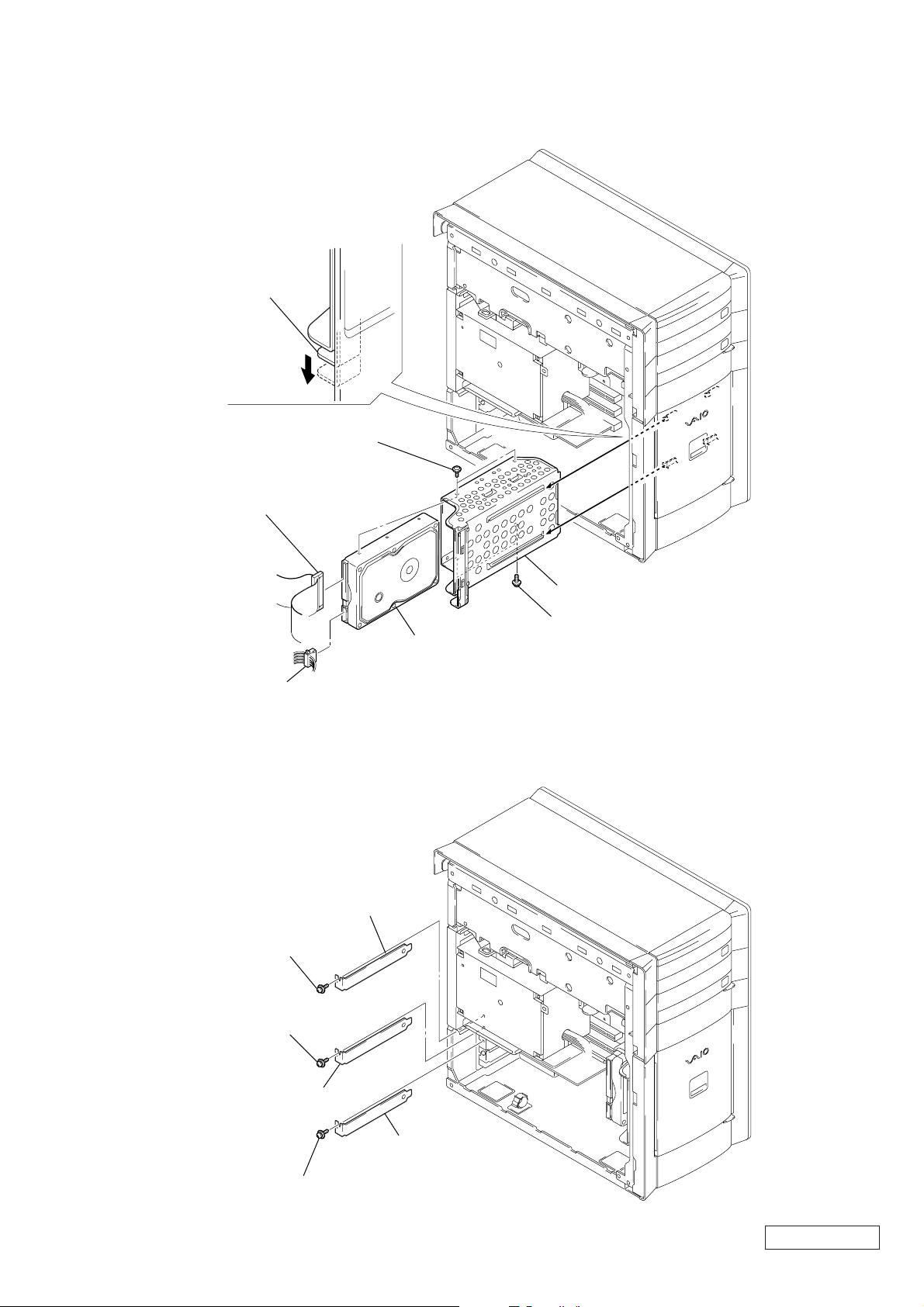
2-6. HDD
3
Push the lever.
1
harness
(IDE/ATA)
5
two screws
(SW) (No.6-32UNC)
2
power connector
2-7. PCI SLOT PANEL
1
screw
(SW) (No.6-32UNC)
3
screw
(SW) (No.6-32UNC)
2
PCI slot panel
6
HDD
4
HDD bracket ass’y
5
two screws
(SW) (No.6-32UNC)
4
PCI slot panel
5
screw
(SW) (No.6-32UNC)
6
PCI slot panel
2-5
Confidential
PCV-RX6__Series (AM)
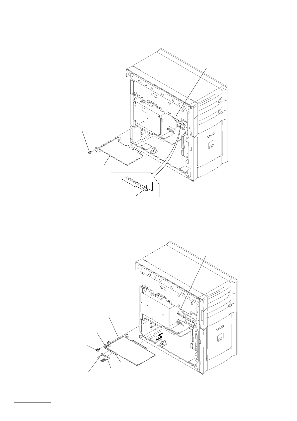
2-8. VGA CARD
1
screw
(SW) (No.6-32UNC)
3
AGP
VGA card
2-9. MOUNTED PWB ENX-15
4
3
screw
(SW) (No.6-32UNC)
2
Remove the mounted
PWB ENX-15 in the
direction of arrow
CN8
A
Push the clip.
PC12
.
A
Confidential
PCV-RX6__Series (AM)
2
harness
(audio)
CN9
1
harness (audio)
2-6
2-10. MODEM CARD
3
)
1
screw
(SW) (No.6-32UNC)
PCI
2
modem card
2-11. PANEL ASS’Y (UPPER) (FOR 2 BAY)
3
two claws
4
panel ass’y (upper) (for 2 bay
2
two claws
2-7
1
Open the door (FDD) ass’y.
Confidential
PCV-RX6__Series (AM)
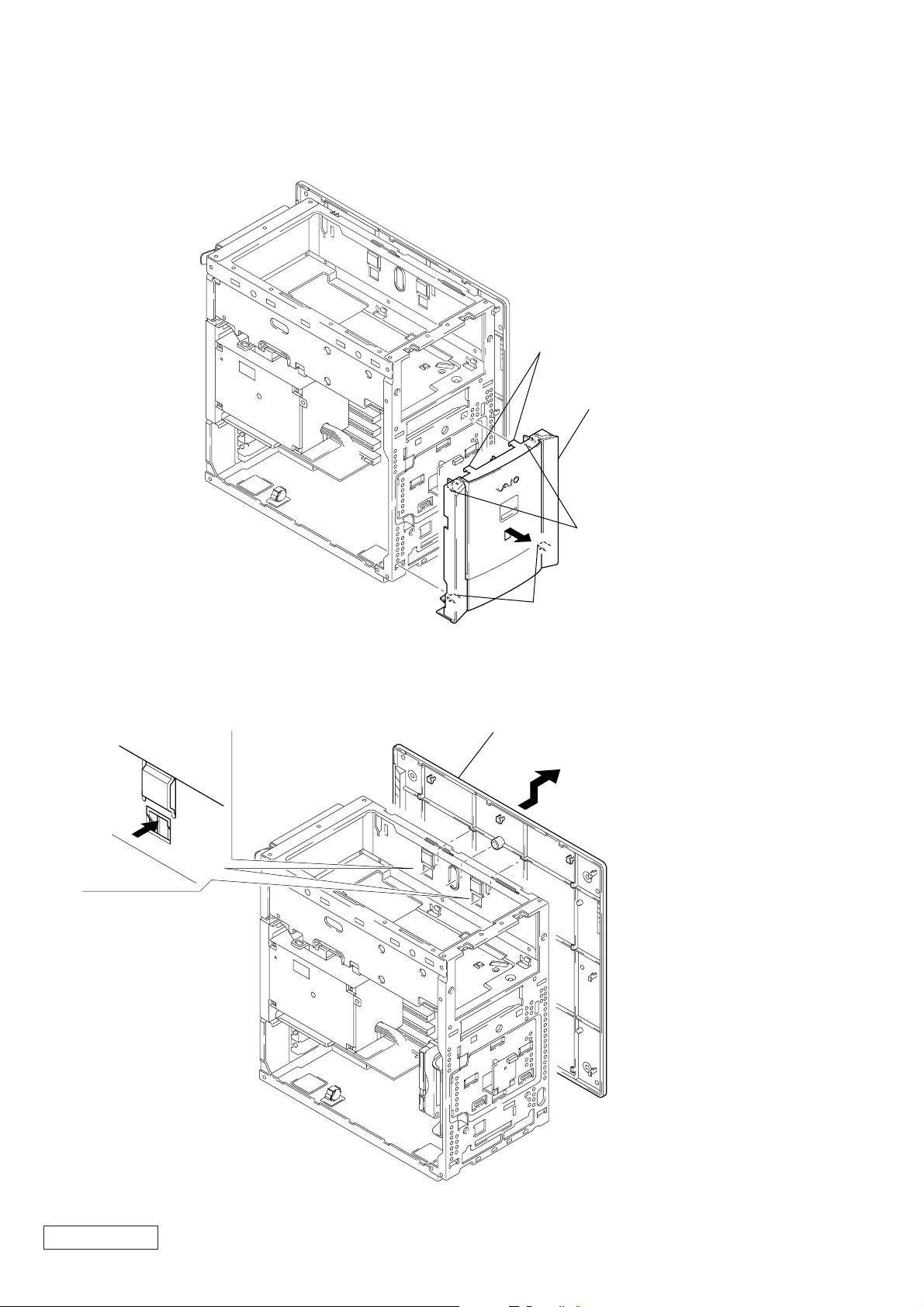
2-12. PANEL ASS’Y (LOWER) (U)
)
A
3
two claws
4
Remove the
front panel ass’y (lower) (U
in the direction of arrow A.
2
two claws
2-13. RIGHT PANEL
1
two claws
1
two claws
2
Remove the right panel
in the direction of arrow
A
A
.
Confidential
PCV-RX6__Series (AM)
2-8
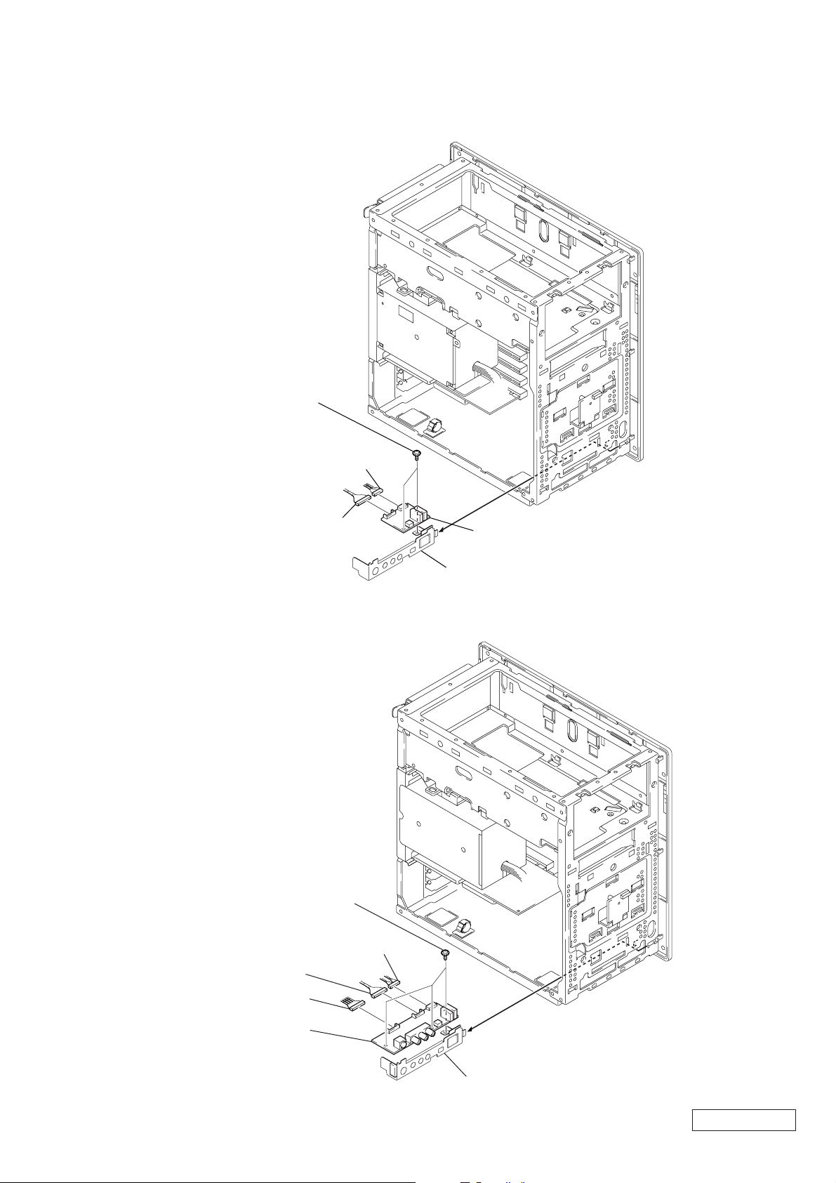
2-14. CNX-138 BOARD
4
two screws
(SW) (No.6-32UNC)
2
harness
(USB/LU)
1
harness
(1394)
A
5
CNX-138 board
2-15. CNX-137 BOARD
5
three screws
(SW) (No.6-32UNC)
2
harness
(1394)
3
harness
(USB/LU)
3
Remove the bracket AV ass’y
in the direction of arrow
A
.
1
harness (AUDIO)
6
CNX-137 board
2-9
A
4
Remove the bracket AV ass’y
in the direction of arrow
A
.
Confidential
PCV-RX6__Series (AM)

2-16. SWX-66 BOARD
)
4
LED shield
3
SWX-66 board
1
harness
(SW/LED)
2
screws
(SW) (No.6-32UNC
2-17. FDD
3
1
harness (FDD)
Push the lever.
4
Remove the FDD
bracket ass’y in the
direction of arrow
2
harness
A
.
A
Confidential
PCV-RX6__Series (AM)
5
two screws
(PWH3
×
5)
6
FDD
2-10
 Loading...