

Page 1
Video
Communication
System
2-649-306-11 (1)
クイックスタートガイド JP
最初にお読みください!
Quick Start Guide GB
Please read it before proceeding!
Guide de démarrage rapide FR
Lisez-le avant de continuer!
Kurzanleitung DE
Lesen Sie sie bitte, bevor Sie fortfahren!
Guía de inicio rápido ES
Lealo antes de continuar!
Guida introduttiva IT
Leggere attentamente prima di procedere!
CS
Guia de Início Rápido PT
Leia antes de continuar!
PCS-TL30
© 2005 Sony Corporation
Page 2

安全のために
ソニー製品は安全に充分配慮して設計されています。しかし、電気製品は、まち
がった使いかたをすると、火災や感電などにより死亡や大けがなど人身事故につ
ながることがあり、危険です。
事故を防ぐために次のことを必ずお守りください。
安全のための注意事項を守る
4 〜 6 ページの注意事項をよくお読みください。
警告表示の意味
取扱説明書および製品では、次の
ような表示をしています。表示の
内容をよく理解してから本文をお
読みください。
定期点検をする
長期間、安全にお使いいただくために、定期点検をすることをおすすめします。
点検の内容や費用については、お買い上げ店またはソニーのサービス窓口にご相
談ください。
故障したら使わない
すぐに、お買い上げ店またはソニーのサービス窓口にご連絡ください。
万一、異常が起きたら
• 煙が出たら
• 異常な音、においがしたら
• 内部に水、異物が入ったら
• 製品を落としたり、キャビネットを破損したときは
m
a 電源を切る。
b 電源コードや接続コードを抜く。
c お買い上げ店またはソニーのサービス窓口に連絡する。
この表示の注意事項を守らないと、
火災や感電などにより死亡や大け
がなど人身事故につながることが
あります。
この表示の注意事項を守らないと、
感電やその他の事故によりけがを
したり周辺の物品に損害を与えた
りすることがあります。
注意を促す記号
行為を禁止する記号
行為を指示する記号
2
Page 3

目次
警告.....................................................................4
注意.....................................................................5
付属の説明書について...............................................7
本機の特長.................................................................7
持ち運びのできる一体型ビデオコミュニケーショ
ンシステム .....................................................7
使いやすいユーザーインターフェース................7
コンピューターディスプレイとしても
使用可能.........................................................8
付属品を確認する......................................................8
各部の名称と働き......................................................8
インジケーターの名称と機能 ............................10
システムの接続 .......................................................11
接続端子の使いかた ..........................................11
接続上のご注意..................................................11
接続例(単独で使用).........................................12
コンピューターとの接続例
(マウスを個別に使用).................................12
コンピューターとの接続例(マウスを共用).....12
電源を入れる /切る................................................13
レンズカバーを開ける.......................................13
電源を入れる .....................................................13
初期設定ウィザード ..........................................14
電源を切る.........................................................14
スタンバイ状態にする.......................................14
ビデオ会議画面とコンピューター画面を
切り換える.........................................................15
本機の高さを調節するには .....................................16
本機の性能を保持するために..................................16
使用・保管場所について ...................................16
液晶画面について ..............................................16
液晶ディスプレイパネルについて.....................17
内蔵スピーカーについて ...................................17
お手入れについて ..............................................17
仕様 .........................................................................17
RGB 入出力仕様.................................................19
このクイックスタートガイドには、事故を防ぐための重要な
注意事項と製品の取り扱いかたを示しています。このクイッ
クスタートガイドをよくお読みのうえ、製品を安全にお使い
ください。お読みになったあとは、いつでも見られるところ
に必ず保管してください。
また、付属の CD-ROM には、本機のより詳しい情報を記載
した取扱説明書が収録されています。クイックスタートガイ
ドと併せてお読みください。
JP
目次
3
Page 4
AC 電源コードや DC 電源接
たこ足配線をしない
配線器具をたこ足配線して定格を超えた
電流が流れると、火災などの原因となり
ます。
AC アダプターの AC プラ
グ、DC プラグは根元まで差
し込む
しっかり根元まで差し込まないと、火災
や感電の原因となります。
続コードを傷つけない
AC 電源コードや DC 電源接続コードを
傷つけると、火災や感電の原因となるこ
とがあります。
• コードを加工したり、傷つけたりしな
い。
• 重いものをのせたり、引っ張ったりし
ない。
• 熱器具に近づけたり、加熱したりしな
い。
• コードを抜くときは、必ずプラグを
持って抜く。
万一、コードが傷んだら、ソニーのサー
ビス窓口に交換をご依頼ください。
雨のあたる場所や、油煙、湯
気、ほこりの多い場所には置
かない
火災や感電の原因となることがありま
す。
雷が鳴り出したら、電源プラ
ネットワークコネクターに指
定以外のネットワークや電話
回線を接続しない
本機のネットワークコネクターに次の
ネットワークや回線を接続すると、コネ
クターに必要以上の電流が流れ、故障や
発熱、火災の原因となります。
特に、ホームテレホンやビジネスホンの
回線には、絶対に接続しないでくださ
い。
• 10BASE-Tと 100BASE-TX タイプ以外
のネットワーク
• 一般電話回線
• ISDN(デジタル)対応公衆電話のデ
ジタル側のジャック
• PBX(デジタル式構内交換機)回線
• ホームテレホンやビジネスホンの回線
• 上記以外の電話回線など
また、ネットワークコネクターをお使い
になるときは、職場などのネットワーク
管理者にご相談ください。
グには触れない
感電の原因になります。
落雷のおそれがあるときは本
機を使用しない
落雷により、感電したり本機が故障する
ことがあります。雷が予測されるとき
は、火災や感電、製品の故障を防ぐため
にネットワークケーブルや電源プラグを
抜いてください。また、雷が鳴りだした
ら、本機には触らないでください。
4
警告
Page 5
ぬれた手で AC アダプターに
さわらない
感電の原因となることがあります。
分解や改造をしない
火災や感電、けがの原因となることがあ
ります。内部の点検や修理はお買い上げ
店またはソニーのサービス窓口にご依頼
ください。
不安定な場所に設置しない
ぐらついた台の上や傾いたところに設置
すると、倒れたり落ちたりしてけがの原
因となることがあります。また、設置・
取り付け場所の強度を充分にお確かめく
ださい。
通風孔をふさがない
通気孔をふさぐと、本機内部に熱がこも
り、発煙、発火などが起こり、やけどの
原因になることがあります。
接続の際は電源を切る
電源を入れたままで電源コードや接続
ケーブルを接続すると、感電や故障の原
因になることがあります。
付属の AC アダプターや電源
コードを使う
付属の AC アダプターや電源コードを使
わないと、感電や故障の原因になること
があります。
付属の AC アダプターは指定
された製品以外には使用しな
お手入れの際は、電源を切っ
て電源プラグを抜く
電源を接続したままお手入れをすると、
感電の原因となることがあります。
移動させるときは電源コード、
接続コードを抜く
接続したまま移動させると、コードが傷
つき、火災や感電の原因となることがあ
ります。
直射日光に当たる場所、熱器
具の近くには置かない
変形したり、故障したりするだけでな
く、レンズの特性により火災の原因とな
ります。特に窓際に置くときなどはご注
意ください。
内部に水や異物を入れない
水や異物が入ると火災や感電の原因とな
ることがあります。
万一、水や異物が入ったときは、すぐに
電源を切り、電源コードや接続コードを
抜いて、お買い上げ店またはソニーの
サービス窓口にご相談ください。
い
指定された製品以外に使用すると、故障
の原因になることがあります。
ぬれた手で電源プラグにさわ
らない
ぬれた手で電源プラグの抜き差しをする
と、感電の原因となることがあります。
通電中の本体や AC アダプ
ターに長時間触れない
温度が相当上がることがあります。
長時間皮膚が触れたままになっている
と、低温やけどの原因になることがあり
ます。
注意
5
Page 6
排気口からの排気に長時間あ
コード類は正しく接続・配置
たらない
本機をご使用中、その動作状況により排
気口から温風が排出されることがありま
す。
この温風に長時間あたると、低温やけど
の原因となる場合があります。
長時間使用しないときは電源
ケーブルや AC アダプターの
プラグを抜く
長時間使用しないときは、安全のため
AC アダプターのプラグをコンセントか
ら抜いてください。
ディスプレイ画面を長時間継
続して見ない
ディスプレイなどの画面を長時間継続し
て見続けると、目が疲れたり、視力が低
下するおそれがあります。
ディスプレイ画面を見続けて体の一部に
不快感や痛みを感じたときは、すぐに本
システムの使用をやめて休息してくださ
い。
万一、休息しても不快感や痛みがとれな
いときは、医師の診察を受けてくださ
い。
する
電源コードや信号ケーブルは、足に引っ
かけると製品の落下や転倒などによりけ
がの原因となることがあります。人が踏
んだり、引っかかったりするような恐れ
のある場所を避け、十分注意して接続・
配置をしてください。
転倒、移動防止の処理をする
本製品をラックに取り付けたり、取り外
すときは、転倒・移動防止の処置をしな
いと、倒れたり、動いたりして、けがの
原因となることがあります。安定した姿
勢で注意深く作業してください。また、
ラックの設置状況、強度を十分にお確か
めください。
製品の上に乗らない、重いも
のを乗せない
倒れたり、落ちたり、壊れたりして、け
がの原因となることがあります。
液晶画面に衝撃を与えない
液晶画面はガラスでできています。
重い物をのせたり、落としたり、画面を
強打したりしないでください。
強い衝撃を与えると液晶が割れて、故障
やけがの原因となることがあります。
6
注意
Page 7
付属の説明書について
本機には、このクイックスタートガイドをはじめとして、
次の説明書が付属しています。目的に応じてお読みくださ
い。
2
「 Japanese」というファイル名の PDF をダブルクリック
する。
AdobeReader が起動し、本機の取扱説明書の表紙が画
面に表示されます。
「目次」の各項目をクリックすると、その見出しのペー
ジが表示されます。
クイックスタートガイド(本書)
システムの接続方法や、初期設定などを簡単に説明してい
ます。(付属の CD-ROM にも同じクイックスタートガイド
が収録されています。)
取扱説明書(付属の CD-ROM 内)
本機の詳しい操作方法や会議に必要なさまざまな設定など、
本機の機能をすべて説明しています。
CD-ROMの動作環境
付属の CD-ROMを動作させるには、次の環境が必要です。
• コンピューター:Intel
ンピューター
−搭載メモリー:64MB以上
−CD-ROMドライブ:8倍速以上
• ディスプレイモニター:解像度 800×600ドット以上
• OS:Microsoft
WindowsXPHomeEdition
上記の条件を満たさない環境では、CD-ROMの動作が遅
くなったり、まったく動作しない場合があります。
®
®
Pentium®プロセッサー搭載のコ
Windows®XPProfessionalまたは
準備
付属の CD-ROMに収録されている取扱説明書を使用するた
めには、以下のいずれかのソフトウェアがコンピューター
にインストールされている必要があります。
• Adobe
• AdobeReader6.0以上
AdobeReaderがインストールされていない場合は、下記の
URLよりダウンロードできます。
http://www.adobe.co.jp/products/acrobat/readstep2.html
メモ
®
Acrobat®Reader4.0以上
• Adobe、Acrobat は AdobeSystemsIncorporated(アドビシス
テムズ社)の商標です。
• Windows は、米国 MicrosoftCorporation のアメリカ合衆国およ
び他の国における登録商標です。
• Intel、Pentium は、アメリカ合衆国およびその他の国における
インテルコーポレーションまたはその子会社の商標または登録
商標です。
• IPELAおよび はソニー株式会社の商標です。
本機の特長
ビデオコミュニケーションシステム PCS-TL30は、ネット
ワークを通じ映像と音声を送受信することにより、相手側
と同席しているかのように会議ができるビデオ会議システ
ムです。日本国内だけでなく、海外とも簡単に接続できま
す。
持ち運びのできる一体型ビデオコミュ
ニケーションシステム
カメラ、モニター、コーデック部からマイク、スピーカー
までが小型のキャビネットに一体化されており、小型軽量
なので、簡単に持ち運びができます。また、VESA マウン
トに対応しており、さまざまな場所に設置できるため、会
議の場所を選びません。
17型ワイドディスプレイとデジタルパン・チルト・ズーム
対応カメラを内蔵しています。
使いやすいユーザーインターフェース
取扱説明書の見かた
1
CD-ROM ドライブに付属の CD-ROM「Manualsfor
VideoCommunicationSystem」を挿入する。
しばらくすると、画面に CD-ROM の内容が表示されます。
ユーザーインターフェースに透過型のデザインを採用し、
付属のマウスを使用して操作を行います。また、ディスプ
レイには、操作案内用のメッセージとヘルプが表示されま
す。
付属の説明書について/本機の特長
7
Page 8
コンピューターディスプレイとしても
1 423
使用可能
本機は、単独で使用するだけでなく、コンピューターと接
続してディスプレイとしても使用できます。コンピュー
ターと接続する場合は、本機とコンピューターのそれぞれ
にマウスを接続するか、1 つのマウスを共用します。
別売りのデータソリューションモジュール PCSA-DSM1 を
使用して、ディスプレイに表示されているコンピューター
の画像をビデオ会議の相手に伝送できます。
• オプティカルマウス PCS-RMU1(1)
• AC アダプター PCS-AC19V6A または PCGA-AC19V7(1)
単独で使用 コンピューターと
接続して使用 (個別
にマウスを使用 )
コンピューターと接続して
使用 ( マウスを共用 )
付属品を確認する
梱包箱から取り出したら、以下のものが揃っているか確認
してください。
• PCS-TL30 本体(1)
• 電源コード(1)
• クイックスタートガイド(本書)(1)
• CD-ROM(取扱説明書)(1)
• B&Pワランティブックレット(1)
• 保証書(1)
ヒント
付属の CD-ROM には、本機の詳しい操作方法やさまざまな
設定方法が記載されている「取扱説明書」(PDF)が収録さ
れています。
各部の名称と働き
前面
付属品を確認する/各部の名称と働き
8
5
6
7
8
9
q;
qa
qs
qd
qf
qg
Page 9
a タリ−ランプ
相手側に自分の映像が送信されているときに点灯します。
o メモリースティックインジケーター
メモリースティックスロットの状態を表します。
b カメラレンズ
c レンズカバー開閉レバー
カメラを隠すカバーを開閉します。
d マイク
e (音量)ボタン
音量を調整します。
+:音量が大きくなります。
−:音量が小さくなります。
f (ヘッドホン)端子(ステレオミニジャック)
ヘッドホン(市販)と接続します。
g (マイク)端子(ミニジャック)
別売りのマイクロホン PCS-A1または PCSA-A3を接続し
ます。
h スピーカー
i オンラインランプ
主に、発着信についての状態を示します。
j マイクオフボタンとインジケーター
自分側からの音声を相手に送るのを中断するときに押しま
す。再び音声を相手に送るときは、もう一度押します。
ご注意
点灯中はメモリースティックを抜かないでください。
後面
1
a リアカバー
リアカバーをはずすと、内部にコネクターパネルがありま
す。また、内部にはスタンド部分とディスプレイ部分の接
続部があり、ネジ留め位置を変えると高さを調節できます。
k (ビデオ会議)ボタンとインジケーター
コンピューター画面からビデオ会議画面に切り換えるとき
に押します。
l (PC)ボタンとインジケーター
コンピューター画面に切り換えるときに押します。
m (メニュー)ボタン
設定メニューを表示するときに押します。
n (電源)スイッチとインジケーター
本機の電源を入 /切します。
PC モードでコンピューターディスプレイとして使用中は、
スイッチを一度押すと電源が切れます。
VC モードでスイッチを一度押すとスタンバイ状態になり
ます。電源を切るときは、5 秒以内にもう一度押してくだ
さい。
ご注意
通話中は、電源スイッチは機能しません。
右側面
1
a メモリースティックスロット
メモリースティックを挿入します。
各部の名称と働き
9
Page 10

コネクターパネル部
7653421
(リアカバー内、下から見た図)
a DC19.5V端子
付属の ACアダプター PCS-AC19V6A または PCGAAC19V7 を接続します。
b AUDIOIN(PC用音声入力)端子(ステレオミニ
ジャック)
RGBIN端子に接続したコンピューターの音声出力端子と
接続します。
c RGBIN(RGB入力)端子(ミニ D-sub15ピン)
コンピューターの RGB出力端子と接続します。
d 100BASE-TX/10BASE-T端子(RJ-45)
カテゴリー 5のケーブルを使ってハブなどに接続します。
リンク・データ・インジケーター(緑)と 100/10Mbps イ
ンジケーター(オレンジ)がついています。
e PC 端子
RGBIN端子に接続したコンピューターと、マウスを共用する
場合に使用します。コンピューターの USB 端子と接続します。
ご注意
USB ケーブルは、長さ 3m 以下のものをお使いください。
f RS232C 端子(D-sub9ピン)
サービス用です。
インジケーターの名称と機能
インジケーター 状態 意味
(電源)* 緑点灯 電源オン
オレンジ点灯 スタンバイ
オレンジ点滅
(1 秒周期)
消灯 電源オフ
オンライン * 青点滅(3 回 /秒)発着信中
青イルミネー
ション点灯
青間欠点滅 不在着信あり
消灯 オフライン(不在着信なし)また
(PC)* 青点灯 コンピューター画面を表示中
白点灯 ビデオ会議画面を表示中
消灯 スタンバイ
(ビデオ会議)*
(マイクオフ)*
(メモリー
スティック)
タリーランプ オレンジ点灯 カメラ映像を相手に送信中(レン
リンク・データ 緑点灯 リンク・アップ
100/10Mbps オレンジ点灯 100Mbps
青点灯 ビデオ会議画面を表示中
白点灯 コンピューター画面を表示中
消灯 スタンバイ
オレンジ点灯 マイクオフ
白点灯 マイクオン
消灯 スタンバイ
オレンジ点灯 アクセス中
消灯 非アクセス中
オレンジ点滅
(5 秒周期)
消灯 カメラ映像送信停止
緑点滅 データ・アクティブ
消灯 リンク・ダウン
消灯 10Mbps
FAN 異常
通信中
はスタンバイ
ズカバー開)
Closed 映像を相手に送信中(レン
ズカバー閉)
g マウス端子
付属のオプティカルマウス PCS-RMU1 を接続します。
各部の名称と働き
10
*本体の起動中は点灯します。温度異常を検出すると点滅し、電
源を落とします。
Page 11

システムの接続
接続上のご注意
ここでは、代表的なシステムの接続のしかたを説明します。
本機は、単独で使用するだけでなく、ビデオ会議をしてい
ないときにはコンピューター用のディスプレイとしても使
用できます。コンピューターと接続する場合は、本機とコ
ンピューターのそれぞれにマウスを接続するか、本機とコ
ンピューターを市販の USB ケーブルで接続することによっ
てマウスを共用します。
接続端子の使いかた
接続端子はリアカバーの内側にあります。
リアカバーを外してケーブルを接続し、接続終了後に再び
リアカバーを取り付けてください。
リアカバーを外すには
手前に引っぱります。
• 必ず本機に付属のACアダプターと電源コードをご使用く
ださい。
• ACアダプターのACプラグとDCプラグは根元までしっか
り差し込んでください。
• 安全のために、100BASE-TX/10BASE-T 端子を過電圧が
加わるおそれのあるネットワークなどに接続しないでく
ださい。
• 接続するときは、必ず各機器の電源を切ってから行って
ください。
• 本機が壊れますので、電源を入れたままケーブルを抜き
差ししないでください。
接続端子(リア
カバーの内側)
リアカバーを取り付けるには
4 か所の突起を合わせ、押し付けます。
システムの接続
11
Page 12
接続例(単独で使用)
接続 1 〜 5 の順に接続してください。
3 DC19.5V へ
ビデオコミュニケーション
システムPCS-TL30
100BASE-TX/2
10BASE-T へ
AC アダプターPCS-AC19V6A
または PCGA-AC19V7
(付属)
1 マウス端子へ
UTP ケーブルカテゴリー 5(ストレート、市販)
コンピューターとの接続例(マウスを個別に使用)
ビデオコミュニケーション
システム PCS-TL30
マウス端子へ
4 電源コード(付属)
5 電源コンセント
(AC100V)へ
オプティカルマウス
PCS-RMU1(付属)
LAN へ
オプティカルマウス
PCS-RMU1(付属)
RGBIN へ
AUDIOIN へ
オーディオコード(ステレオ
ミニプラグ)(市販)
コンピューターとの接続例(マウスを共用)
ビデオコミュニケーション
システム PCS-TL30
AUDIO
IN へ
マウス端子へ
PC
RGB
IN へ
端子へ
ミニ D-sub15 ピン
ケーブル(市販)
音声出力へ
USB ケーブル(市販)*
RGB 出力へ
コンピューター
オプティカルマウス
PCS-RMU1(付属)
USB へ
12
*USB ケーブルは、長さ 3m 以下
のものをお使いください。
システムの接続
ミニ D-sub15 ピンケーブル(市販)
オーディオコード(ステレオ
ミニプラグ)(市販)
RGB 出力へ
音声出力へ
コンピューター
Page 13
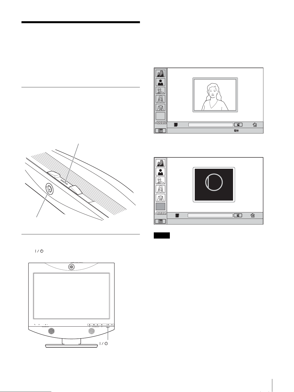
電源を入れる /切る
スイッチのインジケーターがオレンジ色に点灯し、本機の
電源が入ります。起動が完了すると緑色に点灯します。
ディスプレイにはランチャーメニューが表示され、自分側
のカメラが写している映像も表示されます。
本機の電源を入れる前に、システム全体を正しく接続して
ください。
画面はソフトウェアにより異なることがあります。
レンズカバーを開ける
本機には、カメラを隠すためのレンズカバーがついていま
す。ビデオ会議を始める前に、本体上部のレンズカバー開
閉レバーを右にスライドさせ、必ずレンズカバーを開けて
ください。レンズカバーが閉まったままでは、自分側の映
像が相手に見えません。
レンズカバー開閉レバー
ランチャーメニュー
EMPTY
Number :
アイコンにマウスカーソルを合わせてクリックしてください。
レンズカバーが閉まっているときは、ランチャーメニュー
が次のように表示されます。
CLOSED
Closed
012.345.678.912
カメラ
電源を入れる
本機の (電源)スイッチを押します。
(電源)スイッチ
EMPTY
アイコンにマウスカーソルを合わせてクリックしてください。
Number :012.345.678.912
ご注意
• 電源コードをコンセントに差し、最初に電源スイッチを
押したときは、スイッチのインジケーターが点灯するま
で 10 秒程度かかることがあります。
• 設置後に初めて電源を入れたときは、初期設定用のウィ
ザードが表示されます。ウィザードに従って設定を行っ
てください。
電源を入れる /切る
13
Page 14
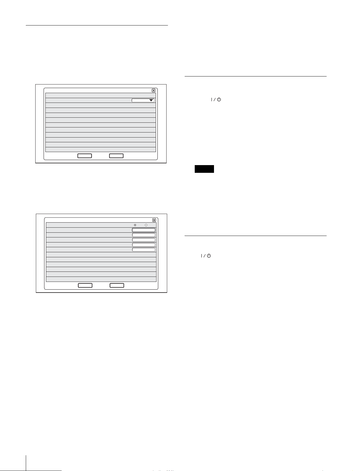
初期設定ウィザード
◆ LANの設定方法がわからない場合は、ネットワーク管理
者にお問い合わせください。
ソフトウェアにより仕様が異なることがあります。
1
Language のプルダウンリストからメニューやメッセー
ジに表示する言語を選ぶ。
Language
2
「Next」をクリックする。
3
LAN に関する設定をする。
DHCPモード
ホストネーム
IP
アドレス
ネットワークマスク
ゲートウェイアドレス
DNSアドレス
Next
終了
Cancel
戻る
English
オート オフ
4
「終了」をクリックする。
設定が保存されます。
電源を切る
1/2
1
本機の (電源)スイッチを 2 度押す。
スイッチを 1 度押すと「本体を待機状態にするときは
そのままお待ちください。電源を切る場合は再度電源
スイッチを押してください。」というメッセージが表示
されるので、もう 1 度電源スイッチを押してください。
2
会議で使用したその他の機器の電源を切る。
ご注意
• 長期間システムを使わないときは、電源を切ってお
いてください。ただし、電源を切ると、会議をする
相手から呼び出しが受けられません。
• PC モードでコンピューターディスプレイとして使用
中は、スイッチを 1 度押すと電源が切れます。
2/2
• 通話中は、電源スイッチは機能しません。
スタンバイ状態にする
本機の (電源)スイッチを押すと、「本体を待機状態に
するときはそのままお待ちください。電源を切る場合は再
度電源スイッチを押して下さい。」というメッセージが表示
されます。そのまま本機の操作をしないでいると、スタン
バイ状態になります。
電源を入れる /切る
14
DHCPモード :
DHCP(DynamicHostConfiguration
Protocol、動的ホスト設定プロトコル)を設定します。
オート :
IPアドレスとサブネットマスク、ゲートウェ
イアドレス、DNSアドレスを自動的に取得しま
す。
オフ :
DHCPを「オフ」に設定します。「オフ」にし
たときは、IP アドレスとサブネットマスク、
ゲートウェイアドレス、DNSアドレスを入力し
てください。
ホストネーム :
IPアドレス :
ネットワークマスク :
ゲートウェイアドレス :
ホスト名を入力します。
本機の IPアドレスを入力します。
サブネットマスクを入力します。
デフォルトゲートウェイアドレ
スを入力します。
DNSアドレス :
DNS(DomainNameSystem)サーバー
アドレスを入力します。
スタンバイ状態の場合は、相手からの呼び出しを受けるこ
とができます。
スタンバイ状態から復帰させるには、電源スイッチを1度
押します。
Page 15
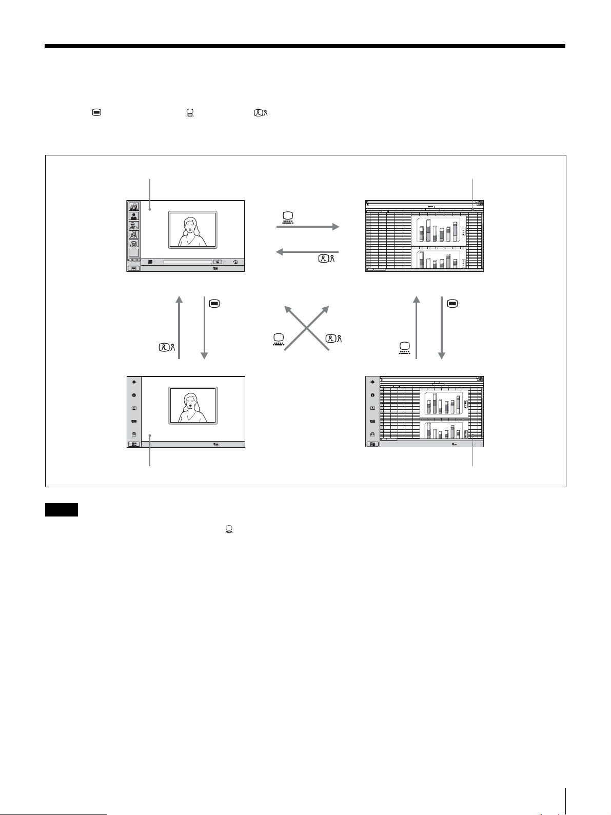
ビデオ会議画面とコンピューター画面を切り換える
本機右下の (メニュー)ボタン、(PC)ボタン、 (ビ
デオ会議)ボタンで、ビデオ会議画面とコンピューター画
面を切り換えることができます。
ビデオ会議画面(ランチャーメニュー) 通常のコンピューター画面
ABCDEFGH IJ KLMN
1
abcd
2
3
12
46
23
34
4
4
5
5
6
6
7
69
8
44
9
10
11
12
13
14
15
16
17
18
19
20
21
22
23
EMPTY
Number :012.345.678.912アイコンにマウスカーソルを合わせてクリックしてください。
24
25
abcd
26
4
27
5
28
6
29
12
30
46
31
69
32
33
34
180
67
45
56
12
26
76
1
6
16
7
76
67
12
16
45
78
7
0
57
38
1
4
0
23
13
15
12
1
2
0
1
0
0
6
0
5
0
4
0
2
0
0
1
3
2
180
0
1
6
45
56
1
4
0
26
76
57
23
1
2
0
23
34
1
0
0
15
12
23
13
6
0
5
0
4
0
d
c
b
a
6
5
4
d
c
b
a
Number :012.345.678.912アイコンにマウスカーソルを合わせてクリックしてください。
ビデオ会議画面(設定メニュー)
ご注意
• コンピューターと接続していない場合は、(PC)ボタン
を押してコンピューター画面に切り換えると、マウス操
作ができなくなります。
• 通話中で子画面を表示している場合は、コンピューター
画面に切り換えても子画面が表示されます。ただし、子
画面に表示される映像は、相手または自分の映像となり
ます。
• 本機とコンピューターに個別にマウスを接続している場
合は、表示中の画面に応じて操作するマウスが異なりま
す。通常のコンピューター画面を表示しているときはコ
ンピューターに接続されているマウスを、その他の画面
を表示しているときは本機に接続されているマウスを操
作してください。
ABCDEFGH IJ KLMN
1
2
abcd
3
12
46
23
34
4
4
5
5
6
6
7
69
8
44
9
10
11
12
13
14
15
16
17
18
19
20
21
22
23
24
25
abcd
26
4
27
5
28
6
29
12
30
46
31
69
32
33
34
180
67
45
56
12
26
76
6
0
1
16
57
38
1
4
0
7
23
13
76
15
12
0
1
2
0
0
1
0
6
0
5
4
0
2
0
0
1
2
180
0
1
6
67
45
56
0
1
4
12
26
76
16
57
23
0
1
2
45
23
34
1
0
0
78
15
12
7
23
13
0
6
0
5
4
0
d
c
b
a
6
4
5
3
d
c
b
a
Number :012.345.678.912アイコンにマウスカーソルを合わせてクリックしてください。
コンピューター画面(設定メニュー)
ビデオ会議画面とコンピューター画面を切り換える
15
Page 16

本機の高さを調節するに
は
本機のスタンド部分とディスプレイ部分は、ネジで固定さ
れています。出荷時は、3 段(25mm 間隔)のネジ穴のう
ちディスプレイが一番低い位置に固定されていますが、固
定するネジ穴を変えることでディスプレイ部分の高さを調
節できます。
1
本機のリアカバーをはずす。
◆ リアカバーのはずしかたは、11 ページをご覧ください。
2
コインなどでネジ(4 個)をはずし、スタンド部分を持
ち上げて、固定したい位置の穴に位置決めピンを差し
込む。
ご注意
高さの調節は、必ず各機器の電源を切り、液晶画面を
下にし、柔らかい布等の上に本機を寝かせた状態で
行ってください。
3
コインなどでネジ(4 個)を締め付けてスタンド部分を
固定する。
4
本機のリアカバーを取り付ける。
本機の性能を保持するた
めに
位置決めピン
使用・保管場所について
次のような場所での使用および保管は避けてください。
• 極端に寒いところや暑いところ。
• 湿気、ほこりの多いところ。
• 激しく振動するところ。
• 強い磁気を発生するものの近く。
• 強力な電波を発生する機器やラジオの送信所の近く。
• 雑音が多いところ。
液晶画面について
• 液晶画面を太陽に向けたままにすると、液晶画面を傷め
てしまいます。窓際や室外に置くときなどはご注意くだ
さい。
• 液晶画面を強く押したり、ひっかいたり、上にものを置
いたりしないでください。画面にムラが出たり、液晶パ
ネルの故障の原因になります。
• 寒い所でご使用になると、画像が尾を引いて見えたり、
画面が暗く見えたりすることがありますが、故障ではあ
りません。温度が上がると元に戻ります。
• 静止画を継続的に表示した場合、残像を生じることがあ
りますが、時間の経過とともに元に戻ります。
• 使用中に画面やキャビネットがあたたかくなることがあ
りますが、故障ではありません。
本機の高さを調節するには/本機の性能を保持するために
16
Page 17

液晶ディスプレイパネルについて
本機の液晶ディスプレイパネルは非常に精密度の高い技術
でつくられていますが、黒い点が現れたり、赤と青、緑の
点が消えないことがあります。また、見る角度によってす
じ状の色むらや明るさのムラが見える場合があります。
これらは、液晶ディスプレイの構造によるもので、故障で
はありません。
これらの点をご了承のうえ、本機をお使いください。
内蔵スピーカーについて
スピーカーからは磁気が発生していますので、磁気テープ
や磁気ディスクなどはスピーカー開口部から離しておいて
ください。データが破損するおそれがあります。
お手入れについて
• お手入れをする前に、必ず電源プラグをコンセントから
抜いてください。
• 液晶の画面は特殊加工がされていますので、なるべく画
面に触れないようにしてください。また画面の汚れをふ
きとるときは、乾いた柔らかい布でふきとってください。
• アルコール、シンナー、ベンジンなどは使わないでくだ
さい。変質したり、塗装がはげたりすることがあります。
• 化学ぞうきんをご使用の際は、その注意書きに従ってく
ださい。
• 殺虫剤のような揮発性のものをかけたり、ゴムやビニー
ル製品に長時間接触させると、変質したり、塗装がはげ
たりすることがあります。
画素 CIF352 ピクセル× 288 ライン
QCIF176 ピクセル× 144 ライン
静止画
画素 704 ピクセル× 576 ライン
圧縮方式
音声
周波数帯域 14kHz(MPEG4Audio)
伝送レート 64kbps、96kbps(MPEG4Audio)
ネットワーク
多重分離化 映像信号、音声信号、データを多重分離
フレームフォーマット
回線 LAN(100BASE-TX/10BASE-T)
サポート LAN プロトコル
H.261(ITU-T 勧告準拠)Annex.D(4CIF)
H.263(独自方式)
7kHz(G.722ITU-T 勧告準拠)
3.4kHz(G.711/G.728/G729ITU-T 勧告準拠)
56kbps、64kbps(G.711ITU-T 勧告準拠)
48kbps、56kbps、64kbps(G.722 ITU-
T 勧告準拠)
16kbps(G.728 ITU-T 勧告準拠)
8kbps(G.729 ITU-T 勧告準拠)
化
H.225.0(ITU-T 勧告準拠)
HTTP
FTP
Telnet
RTP/RTCP
TCP/UDP
IP
仕様
ビデオコミュニケーションシステム PCSTL30
本機は ITU-T 勧告 H.323 と IETFSIP に準拠しています。
ソフトウェアにより仕様が異なることがあります。
動画
動作帯域 64kbps 〜 2048kbps
コーディング方式
H.261/H.263/H.263+/H.263++/H.264
(ITU-T 勧告準拠)
MPEG4SimpleProfile
リモートコントロール
相手カメラコントロール
H.281(ITU-T 勧告準拠)
カメラ
映像素子 1/3.2型カラー CMOS(総画素数約 130
万画素)
レンズ 焦点距離f 2.3mm
F 値 1:2.8
画角 水平:約 88°
垂直:約 73°
最至近撮影距離 300mm
パン・チルト・ズーム機能
デジタル方式
オートホワイトバランス機能搭載
フレームレート 30/15fps
環境照度に合わせ自動切り換え
仕様
17
Page 18

ディスプレイ
サイズ 17.1 型ワイド
解像度 1280 × 768(WXGA)
応答時間 13ms 以内
コントラスト比
600:1
視野角 176゜以上
発色数 1670 万色
ディスプレイコントローラー
PinP 4 隅
PandP 3 画面表示
入力 内部:ビデオ会議用
外部 RGB:コンピューターディスプレイ
ワイド切替 ノーマル、ズーム、ワイド
RGB 切替 640 ×480、800 × 600、1024×768、
1280×768 など、拡大表示可能
スピーカー
スピーカー 3W × 2
動作湿度 20%〜 80%
保存温度 − 20°C 〜+ 60°C
保存湿度 20%〜 80%(結露しないこと)
外形寸法 80 × 40 × 160mm(幅 / 高さ / 奥行き)
質量 約800g
マイクロホン PCS-A1(別売り)
周波数帯域 13kHz
指向特性 無指向性
外形寸法 74 × 16 × 93mm(幅 / 高さ / 奥行き)
質量 約 170g
電源 プラグインパワータイプ
マイクロホン PCSA-A3(別売り)
周波数帯域 13kHz
指向特性 単一指向性
外形寸法 68 × 16 × 96mm(幅 / 高さ / 奥行き)
質量 約 200g
電源 プラグインパワータイプ
マイクロホン
周波数帯域 14kHz
指向特性 単一指向性
その他
電源電圧 19.5V
消費電流 6.15A
動作温度 5°C 〜 35°C
動作湿度 20%〜 80%
保存温度 − 20°C 〜+ 60°C
保存湿度 20%〜 80%(結露しないこと)
外形寸法 424 ×376×95.5mm(幅 / 高さ / 奥行
き)(スタンド除く)
424 ×419×258mm(幅 / 高さ / 奥行
き)(スタンド含む)
質量 約 8kg
付属品 オプティカルマウスPCS-RMU1(1)
AC アダプターPCS-AC19V6A または
PCGA-AC19V7(1)
電源コード(1)
CD-ROM(1)
クイックスタートガイド(1)
B&P ワランティブックレット(1)
保証書(1)
データソリューションモジュール PCSADSM1(別売り)
消費電力 20W 以下
動作温度 5°C 〜 35°C
動作湿度 20%〜 80%
保存温度 − 20°C 〜+ 60°C
保存湿度 20%〜 80%(結露しないこと)
外形寸法 107×250×34mm(幅 /高さ /奥行き)
(突起部含まず)
質量 約 550g
付属品 クイックスタートガイド(1)
B&P ワランティブックレット(1)
保証書(1)
SIP ソフトウェアPCSA-SP1(別売り)
付属品 シリアル番号シール(1)
取扱説明書(1)
仕様および外観は、改良のため予告なく変更することがあ
りますが、ご了承ください。
AC アダプター PCS-AC19V6A または
PCGA-AC19V7
電源 AC100 〜 240V、50/60Hz、1.8A
出力 19.5V、6.15A
動作温度 5°C 〜 35°C
仕様
18
Page 19
本機は「JISC61000-3-2 準用品」です。
JISC61000-3-2準用品とは、日本工業規格「電磁両立性 - 第
3-2 部 :限度値-高調波電流発生限度値 (1 相当たりの入力
電流が 20A 以下の機器 )」を準用し、商用電力系統の高調波
環境目標レベルを考慮して設計・製造した製品です。
この装置は、情報処理装置等電波障害自主規制協議会
(VCCI)の基準に基づくクラス A 情報技術装置です。この
装置を家庭環境で使用すると電波妨害を引き起こすことが
あります。この場合には使用者が適切な対策を講ずるよう
要求されることがあります。
RGB 入出力仕様
本製品のエコーキャンセラーは、日本電信電話株式会社か
らライセンスを受けて開発されたものです。エコーキャン
セラーソフトウェアの著作権は、日本電信電話株式会社が
保有しています。
お客様は、本製品に含まれる技術の一部もしくは全部を、武
器または武器製造関連に使用または販売することはできま
せん。本製品に含まれるソフトウェア及び関連資料の複製、
調査、改変に関する全ての権利は、日本電信電話株式会社及
び弊社に帰属致します。
株式会社リコーが製作、販売したリコービットマップフォ
ントを使用しています。
表示画素数 備考 水平同期周波数
fH(kHz)
640 × 480 VGAmode 31.469 59.94 25.17 H- 負 V- 負
Macintosh13" 35 66.667 30.24 H- 負 V- 負
VGAVESA72Hz 37.861 72.809 31.5 H- 負 V- 負
VGAVESA75Hz 37.5 75 31.5 H- 負 V- 負
VGAVESA85Hz 43.269 85.008 36 H- 負 V- 負
800 × 600 SVGAVESA56Hz 35.156 56.25 36 H- 正 V- 正
SVGAVESA60Hz 37.879 60.317 40 H- 正 V- 正
SVGAVESA72Hz 48.077 72.188 50 H- 正 V- 正
SVGAVESA75Hz 46.875 75 49.5 H- 正 V- 正
SVGAVESA85Hz 53.674 85.061 56.25 H- 正 V- 正
1024 × 768 XGAVESA60Hz 48.363 60.004 65 H- 負 V- 負
XGAVESA70Hz 56.476 70.069 75 H- 負 V- 負
XGAVESA75Hz 60.023 75.029 78.75 H- 正 V- 正
1280 × 768 WXGAVESA60Hz* 47.693 59.992 80.12 H- 負 V- 正
*データソリューションモジュール PCSA-DSM1 での送信はできません。
垂直同期周波数
fV(Hz)
ドットクロック
(MHz)
同期信号極性
仕様
19
Page 20

English
Owner’s Record
The model and the serial numbers are located at the rear.
Record the serial number in the space provided below.
Refer to these numbers whenever you call upon your Sony
dealer regarding this product.
Model No. PCS-TL30 Serial No.
WARNING
To reduce a risk of fire or electric shock,
do not expose this product to rain or
moisture.
To avoid electrical shock, do not open the
cabinet. Refer servicing to qualified
personnel only.
WARNING
Use the AC power adapter provided with this equipment as
a power supply source.
One of the AC power adaptors listed below is supplied.
Manufacture Type No.
Sony PCS-AC19V6A
Sony PCGA-AC19V7
Any other power sources may result in hazards such as a
fire.
Disconnect device of this equipment is the mains plug of
the AC adapter.
The mains plug on this equipment must be used to
disconnect mains power.
Please ensure that the socket outlet is installed near the
equipment and shall be easily accessible.
In the event of abnormal operations, disconnect the mains
plug.
NOTICE
Use the power cord set approved by the appropriate testing
organization for the specific countries where this unit is to
be used.
For the customers in the USA
WARNING
This device complies with Part 15 of the FCC Rules.
Operation is subject to the following two conditions: (1)
This device may not cause harmful interference, and (2)
this device must accept any interference received,
including interference that may cause undesired
operation.
This equipment has been tested and found to comply with
the limits for a Class A digital device, pursuant to Part 15
of the FCC Rules. These limits are designed to provide
reasonable protection against harmful interference when
the equipment is operated in a commercial environment.
This equipment generates, uses, and can radiate radio
frequency energy and, if not installed and used in
accordance with the instruction manual, may cause
harmful interference to radio communications. Operation
of this equipment in a residential area is likely to cause
harmful interference in which case the user will be
required to correct the interference at his own expense.
You are cautioned that any changes or modifications not
expressly approved in this manual could void your
authority to operate this equipment.
The shielded interface cable recommended in this manual
must be used with this equipment in order to comply with
the limits for a computing device pursuant to Subpart B of
Part 15 of FCC Rules.
For the customers in Canada
This Class A digital apparatus complies with Canadian
ICES-003.
Cet appareil numérique de la classe A est conforme à la
norme NMB-003 du Canada
For the customers in Europe
Warning
This is a Class A product. In a domestic environment, this
product may cause radio interference in which case the
user may be required to take adequate measures.
In the case that interference should occur, consult your
nearest authorized Sony service facility.
CAUTION for LAN port
For safety reason, do not connect the LAN port to any
network devices that might have excessive voltage.
20
Page 21
Table of Contents
Supplied Documents.................................22
Features .....................................................22
Integrated portable Video Communication
System............................................... 22
Intuitive user interface ................................ 22
Use as computer display ............................. 23
Verifying Package Contents.....................23
Names and Functions of Parts.................23
Indicator Names and Functions .................. 25
System Connections.................................26
About the connectors .................................. 26
Connection precautions .............................. 26
Connection example (stand-alone use)....... 27
Connection example for use with computer
(separate mouse)................................ 27
Connection example for use with computer
(shared mouse) .................................. 27
Turning the System On/Off.......................28
Opening the Lens Cover ............................. 28
Turning the system on ................................ 28
Initial Setup Wizard.................................... 28
Turning the system off................................ 29
Setting the Video Communication
System to Standby Mode .................. 29
Switching Between Videoconference
Display and Computer Display..........30
Adjusting the Height of the Display.........31
For Best Performance...............................31
Operating or storage location...................... 31
LCD screen ................................................. 31
LCD display panel...................................... 32
Built-in speakers ......................................... 32
Cleaning...................................................... 32
Specifications............................................32
RGB input/output specifications................. 34
This Quick Start Guide provides important precautions
and product-handling instructions for avoiding accident
or injury. To ensure safe operation of the product, read
this guide carefully and retain it for future reference.
Also, refer to the operating instructions stored on the
supplied CD-ROM for more detailed information about
this product. You should refer to this document together
with the Quick Start Guide.
GB
Table of Contents
21
Page 22

Supplied Documents
This product comes with a number of documents, as listed
below. Consult the appropriate document(s) according to
your requirements.
Quick Start Guide (this document)
Gives basic information about initial settings and how to
connect the system. (The supplied CD-ROM also contains
an identical Quick Start Guide file.)
Operating Instructions (on supplied CD-ROM)
Provides detailed information about operation procedures
and settings necessary for conducting various kinds of
videoconference sessions. All functions of the product are
covered in this document.
CD-ROM operation requirements
The following system requirements apply for using the
CD-ROM.
• Computer: Equipped with Intel
- RAM: 64 MB or more
-CD-ROM drive:
• Display: Resolution 800
• Operating System: Microsoft
Professional or Windows XP Home Edition
If the above requirements are not met, CD-ROM
operation may be slow or not possible.
×8 speed or better
®
Pentium® processor
× 600 or better
®
Windows® XP
Viewing the Operating instructions
1
Insert the supplied CD-ROM (labeled “Manuals for
Video Communication System”) into the CD-ROM
drive of the computer.
After a while, a screen listing the contents of the CDROM will appear.
2
Double-click the PDF with the file name “English”.
Adobe Reader will start up and the first page of the
Operating Instructions for the Video Communication
System will be shown on the screen.
By clicking on an entry in the “Content” section, you
can jump directly to the respective page.
• Adobe and Adobe Reader are trademarks of Adobe Systems
Incorporated.
• Microsoft and Windows are registered trademarks of Microsoft
Corporation in the United States of America and other countries.
• Intel and Pentium are trademarks or registered trademarks of Intel
Corporation or of its subsidiaries in the United States of America and
other countries.
• “IPELA” and are trademarks of Sony Corporation.
Features
Preparations
To access the operating instructions on the supplied CDROM, one of the following software applications must be
installed on the computer:
• Adobe
• Adobe Reader 6.0 or later
Note
If Adobe Reader is not installed, you can download it from
the following URL:
http://www.adobe.com
®
Acrobat® Reader 4.0 or later
The PCS-TL30 Video Communication System is a
videoconferencing system that allows natural, face-to-face
communications with a remote party by transmitting and
receiving images and sound via a network. The other party
can be located anywhere, including overseas.
Integrated portable Video
Communication System
All necessary elements of the Video Communication
System including camera, monitor, codec, microphones
and speakers are integrated in a single compact cabinet.
This ensures easy portability and lets you set up a
videoconference almost anywhere.
The built-in 17-type display supports wide mode, and the
built-in camera is equipped with digital pan/tilt and zoom.
Intuitive user interface
The user interface employs an overlay design that lets you
control operations with a simple click of the supplied
mouse. User guidance in the form of messages and on-line
help is also provided.
22
Supplied Documents / Features
Page 23

Use as computer display
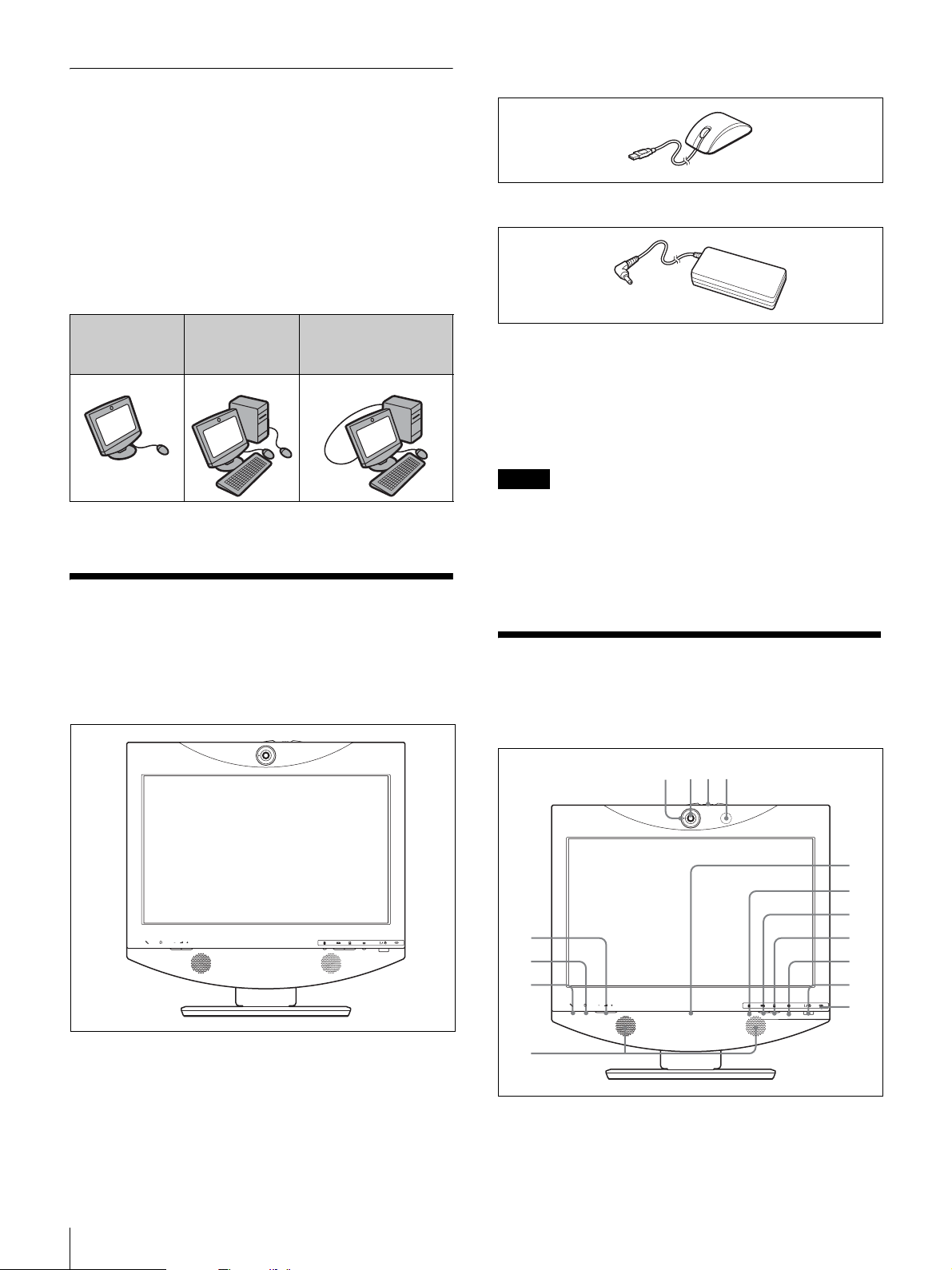
1 423
Besides operating in stand-alone mode, it is also possible
to connect the PCS-TL30 to a computer. In this case, you
can either use different mice for the computer and the PCSTL30, or use a single mouse for both.
The separately available Data Solution Module PCSADSM1 lets you transmit the computer screen content on
the display to the remote party during a videoconference.
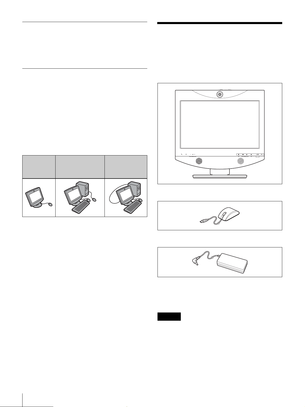
• Optical mouse PCS-RMU1 (1)
• AC adapter PCS-AC19V6A or PCGA-AC19V7 (1)
Stand-alone
use
Use with a computer
and separate
pointing devices
Use with a computer
and a single
pointing device
Verifying Package
Contents
Once you have unpacked the unit, make sure that all of the
following items are present:
• PCS-TL30 main unit (1)
• Power cord (1)
• Quick Start Guide (this document) (1)
• CD-ROM (Operating Instructions) (1)
• Warranty Booklet (1)
Note
The supplied CD-ROM contains the Operating
Instructions which provides detailed information about
operation procedures and all settings. These documents are
supplied as files in PDF format.
Names and Functions of
Parts
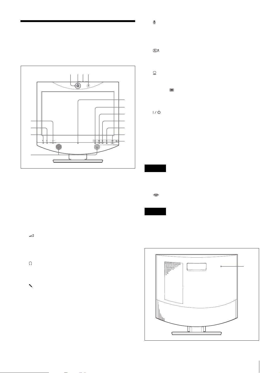
Front view
5
6
7
8
Verifying Package Contents / Names and Functions of Parts
9
q;
qa
qs
qd
qf
qg
23
Page 24

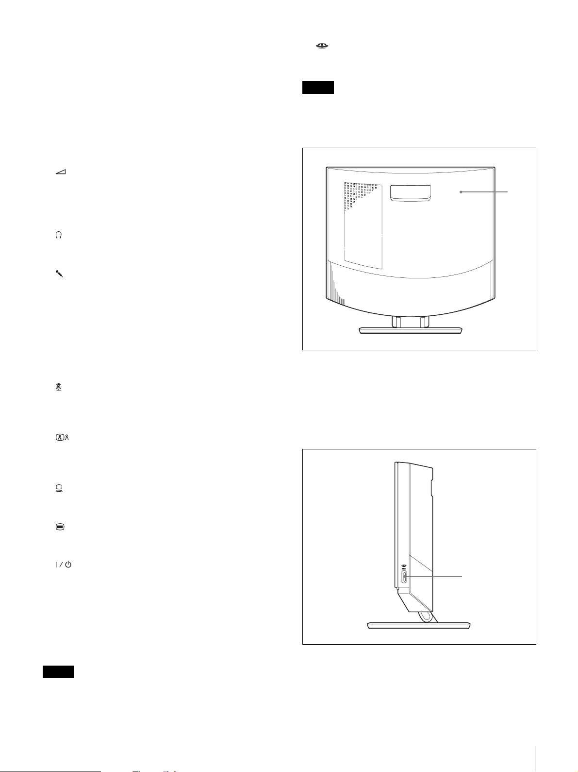
a Tally lamp
Lights up when local video is being sent to the remote
system.
b Camera lens
c Lever for camera lens cover
o “Memory Stick” indicator
Shows the status of the “Memory Stick” slot.
Note
Do not remove the “Memory Stick” when this indicator is
lit.
d Microphone
e (Volume) buttons
Serve to adjust the volume.
+: Increases the volume level.
-: Decreases the volume level.
f (Phones) jack (stereo mini jack)
Lets you connect a pair of headphones (commercially
available).
g (Mic) jack (mini jack)
Allows connection of the optional microphone PCS-A1 or
PCSA-A3.
h Speakers
i Online lamp
Shows mainly the incoming/outgoing call status.
j Mic Off button and indicator
Lets you suppress the sound from the local system. Press
the button again to resume sending the sound to the remote
system.
Rear view
1
a Rear cover
Removing this cover gives access to the connector panel.
The connecting section between the stand and the display
is also located behind the panel. You can adjust the height
of the display by changing the screw positions.
k (Videoconference) button and indicator
Serves for switching from computer screen to
videoconference screen.
l (PC) button and indicator
Serves for switching to computer screen.
m (Menu) button
Press to bring up the Setup menu.
n (Power) switch and indicator
Turns power to the system on and off.
When using the system as a computer screen in PC mode,
pressing the switch once turns the power off.
When using the system in VC mode, pressing the switch
once sets the system to standby mode. To turn the power
off in VC mode, press the switch again within 5 seconds of
the first press.
Note
The power switch does not function during a
communication session.
Right side view
1
a “Memory Stick” slot
A “Memory Stick” can be inserted here.
24
Names and Functions of Parts
Page 25
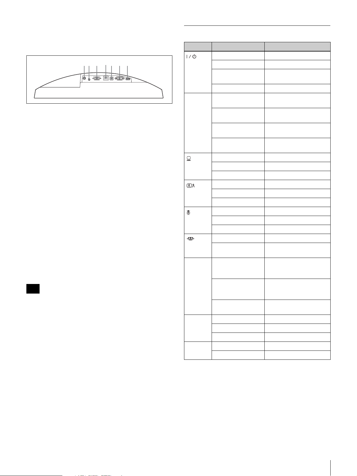
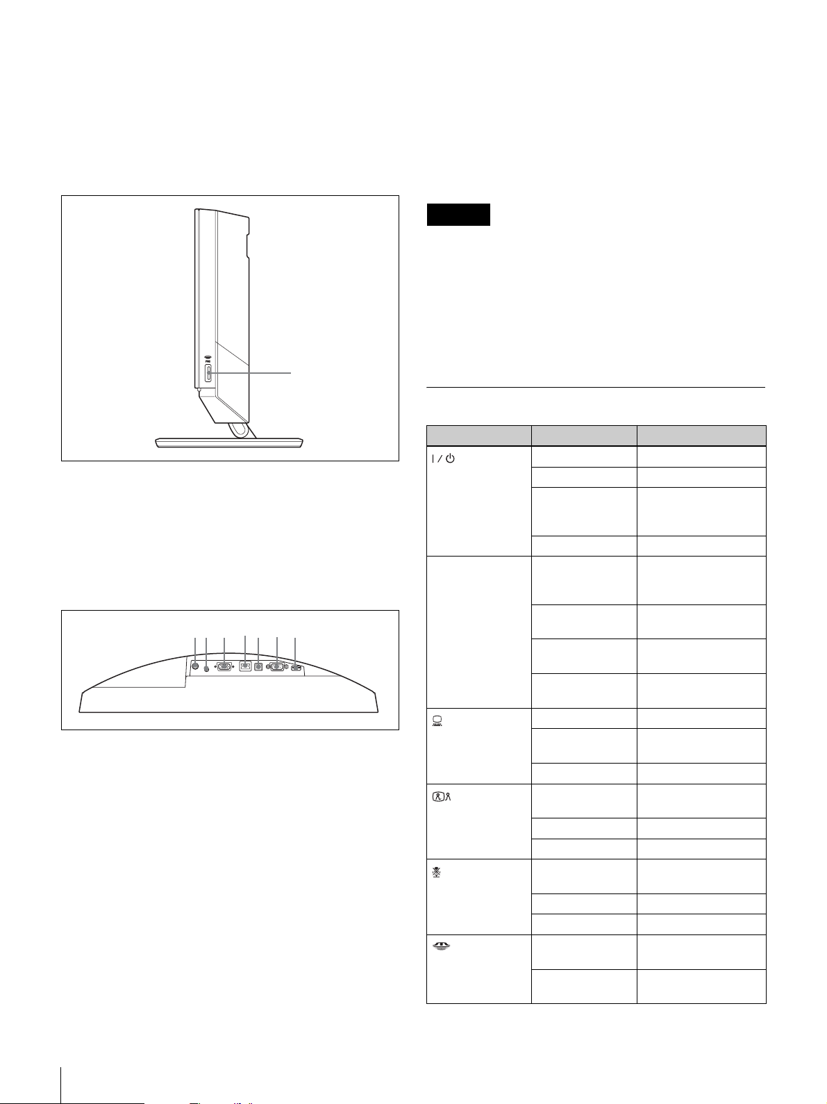
Connector panel
7653421
(section behind rear cover, seen from
below)
a DC19.5V connector
Connect the supplied AC adapter PCS-AC19V6A or
PCGA-AC19V7 here.
b AUDIO IN (PC sound input) jack (stereo mini
jack)
Connect this jack to the audio output of a computer
connected to the RGB IN connector.
c RGB IN connector (15-pin mini D-sub connector)
Connect the RGB output of a computer here.
d 100BASE-TX/10BASE-T port (RJ-45)
Use a Category 5 LAN cable to connect this port to a hub
or similar equipment.
This port is equipped with a Link/Data indicator (green)
and a 100/10 Mbps indicator (orange).
e PC port
This connector is used when the same mouse is to be used
for the PCS-TL30 and for a computer connected to the
RGB IN connector. Link the connector to a USB port on
the computer.
Note
Do not use a USB cable that is more than 3 m (9.84 ft.) in
length.
f RS-232C port (9-pin D-sub connector)
This connector is used only for servicing the system.
g Mouse port
Connect the supplied optical mouse PCS-RMU1 here.
Indicator Names and Functions
Indicator Status Meaning
Lit green Power is on
(Power) *
Online * Flashing blue
(PC) *
(Videocon
ference)
(Mic off) *
(“Memory
Stick”)
Tally lamp Lit orange Camera image being sent
Link/Data Lit green Link is established
100/
10 Mbps
Lit orange Standby
Flashing orange (1second cycle)
Out Power is off
(3 times per sec.)
Blue illumination lit Communication in
Blue intermittent
flashing
Out Offline (no missed call) or
Lit blue Computer display
Lit white Videoconference display
Out Standby
Lit blue Videoconference display
Lit white Computer display
*
Out Standby
Lit orange Mic off
Lit white Mic on
Out Standby
Lit orange
Out Not accessing “Memory
Flashing orange
(5-second cycle)
Out Camera image not being
Flashing green Data is transferring
Out Link is offline
Lit orange 100 Mbps
Out 10 Mbps
Problem with fan
Sending/receiving
progress
Missed call indication
standby
Accessing “Memory Stick”
Stick”
to remote party (lens
cover open)
Closed image being sent
to remote party (lens
cover close)
sent
* The indicator is lit while the system is starting up. If abnormal temperature
is detected, the indicator flashes and power turns off.
Names and Functions of Parts
25
Page 26
System Connections
This section shows some representative system connection
examples.
Besides operating in stand-alone mode, it is also possible
to connect the PCS-TL30 to a computer for use as a display
when no videoconference is in progress. In this case, you
can either use different mice for the computer and the PCSTL30, or connect the PCS-TL30 and the computer with a
generic USB cable and use the same mouse for both.
About the connectors
The connectors of the system are located under the rear
cover. Remove the cover to make connections, and then
replace the cover again.
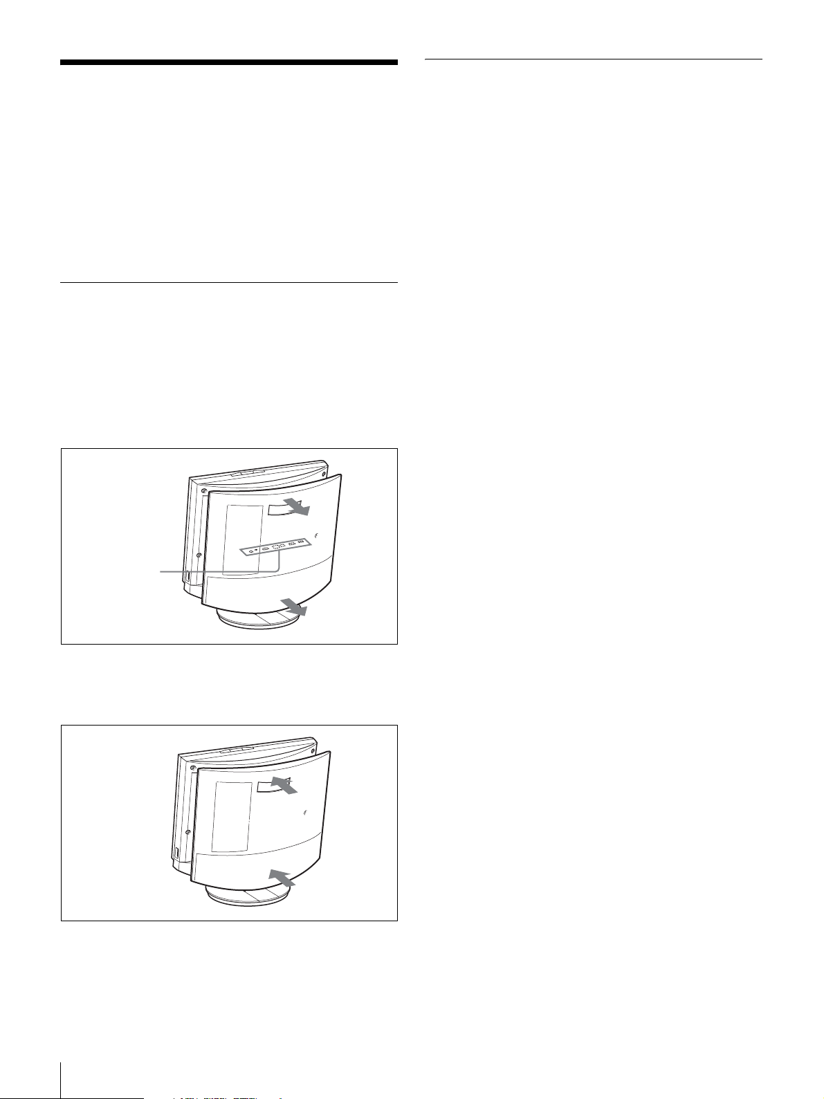
To remove the rear cover
Pull the cover off towards you.
Connection precautions
Warning
• Use only the supplied AC adapter and power cord.
• When connecting the power cord of the AC adapter and
the DC cable, insert the plugs fully and securely.
• For safety, do not connect the 100BASE-TX/10BASE-T
connector to a network where excessive voltages may
occur.
Caution
• Before making any connections, be sure to turn power to
all components off.
• To prevent damage to the unit, do not plug in or
disconnect any cable while power to the unit is turned
on.
Connector panel
(under rear cover)
To attach the rear cover
Push the cover in while aligning the four stubs.
26
System Connections
Page 27
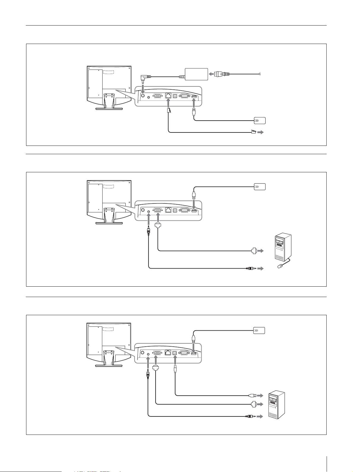
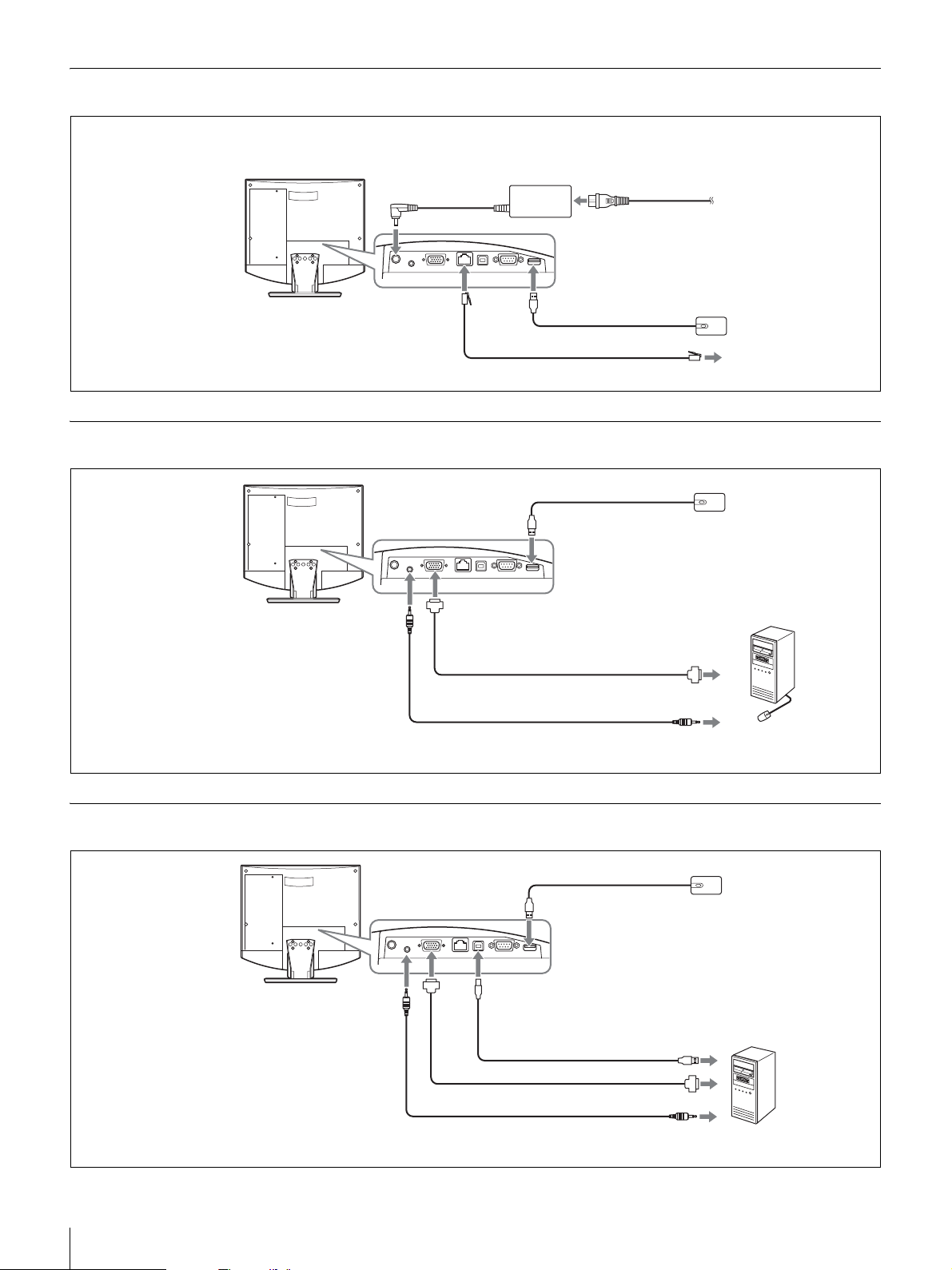
Connection example (stand-alone use)
Make connections in the order 1 - 5.
3 To DC19.5V
connector
Video Communication
System PCS-TL30
To 100BASE-TX/ 2
10BASE-T port
AC adapter PCS-AC19V6A
or PCGA-AC19V7
(supplied)
1 To mouse port
UTP cable Category 5 (straight cable, commercially available)
4 Power cord (supplied)
5 To AC outlet
(120 V AC)
Optical mouse PCS-RMU1
(supplied)
Connection example for use with computer (separate mouse)
Video Communication
System PCS-TL30
To mouse port
To LAN
Optical mouse PCS-RMU1
(supplied)
To AUDIO IN jack
To RGB IN connector
Cable with 15-pin mini
D-sub connector
(commercially available)
Audio cable with stereo mini plug
(commercially available)
To RGB output
To audio output
Connection example for use with computer (shared mouse)
Video Communication
System PCS-TL30
To AUDIO
IN jack
To mouse port
To RGB
IN
connector
To PC port
USB cable
(commercially available) *
To USB port
Computer
Optical mouse PCS-RMU1
(supplied)
* Do not use a USB cable that is
more than 3 m (9.84 ft.) in length.
Cable with 15-pin mini D-sub
connector (commercially available)
Audio cable with stereo mini plug
(commercially available)
To RGB output
To audio output
Computer
System Connections
27
Page 28

Turning the System On/
Off
The indicator of the switch lights up in orange and power
to the Video Communication System comes on. When
powering on is complete, the indicator lights up in green.
The launcher menu appears on the display and the picture
of the local camera is also shown.
Before turning the system on, make sure that system
connections have been completed correctly.
Screens may appear different from those shown here,
depending on the software.
Opening the Lens Cover
The system is equipped with a lens cover to hide the
camera. Before starting a videoconference, open the lens
cover by sliding the lens cover switch on the top of the
system to the right. If the lens cover is closed, the picture
on the local site will not be seen on the remote site.
Lens cover switch
Launcher menu
EMPTY
Click Icon to go into the function.
When the lens cover is closed, the launcher menu appears
as follows.
CLOSED
Closed
Number :012.345.678.912
Camera
Turning the system on
Press the (Power) switch on the PCS-TL30.
(Power) switch
EMPTY
Point to and click on the icon with the mouse.
Notes
Number :012.345.678.912
• The first time the power switch is pressed after the power
cord is plugged into a wall outlet, it may take as long as ten
seconds for the indicator on the switch to light up.
• When you turn on power to the Video Communication
System for the first time after installation, the setup wizard
will appear. Set up your system following the wizard.
Initial Setup Wizard
Some settings may differ slightly depending on the
monitor software.
1
Access the “Language” pull-down list and select the
language to be used for menus and messages.
28
Turning the System On/Off
Page 29
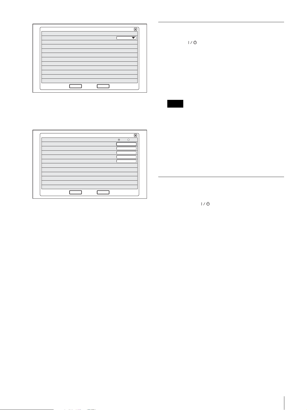
Language
Next
Cancel
English
1/2
Turning the system off
1
Press the (Power) switch twice.
After pressing the switch once, the message “To enter
standby mode, wait for a few moments. To turn off the
power, press the power switch again.” appears. Press
the power switch again.
2
Turn off the power of other equipment used for the
videoconference.
2
Click “Next”.
3
Make the required LAN settings.
DHCP Mode
Host Name
IP Address
Network Mask
Gateway Address
DNS Address
End
Back
DHCP Mode: Sets the DHCP (Dynamic Host
Configuration Protocol).
Auto: Automatically assigns your IP address,
subnet mask, gateway address and DNS
address.
Off: Deactivates DHCP. In this case set your IP
address, subnet mask, gateway address and
DNS address manually.
Host Name: Enter your host name.
IP Address: Enter your IP address.
Network Mask: Enter your subnet mask.
Gateway Address: Enter your default gateway
address.
DNS Address: Enter your DNS (Domain Name
System) server address.
Auto Off
Notes
• Turn the power to the system off when the system
will not be used for an extended period. While the
power is off, you cannot receive a call from a remote
2/2
party.
• When using the system as a computer display in PC
mode, the power turns off with one press of the
power switch.
• During a conference, the power switch does not
function.
Setting the Video Communication
System to Standby Mode
When you press the (Power) switch on the PCS-TL30,
the message “To enter stand-by mode, wait for a few
moments. To turn off the power, press the power button
again.” appears on the display. When you simply wait in
this condition, the system will go into standby mode.
You can receive a call from a remote party in the standby
mode.
To return to normal mode from standby mode, press the
power switch once.
If you do not know the settings required for your LAN
configuration, contact your network administrator.
4
Click “End”.
The settings are saved.
Turning the System On/Off
29
Page 30
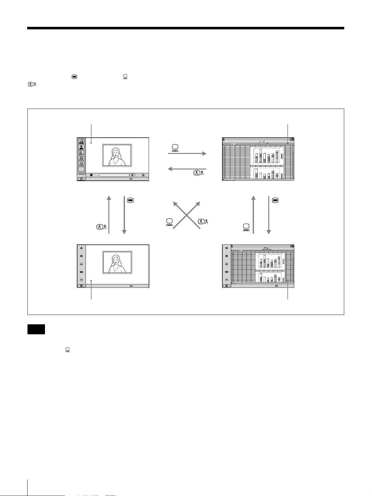
Switching Between Videoconference Display and
Computer Display
You can use the (Menu) button, (PC) button, and
(Videoconference) button at the bottom right of the
unit to switch between the videoconference screen and
computer screen display.
Videoconference screen (launcher menu) Normal computer screen
ABCDEFGH IJ KLMN
1
abcd
2
EMPTY
Click Icon to go into the function.
Number :012.345.678.912
3
4
5
6
7
8
9
10
11
12
13
14
15
16
17
18
19
20
21
22
23
24
25
26
27
28
29
30
31
32
33
34
46
23
12
67
45
4
12
26
5
16
57
6
7
23
69
15
44
76
abcd
45
67
4
26
12
5
57
16
6
23
45
12
15
78
46
23
7
69
34
180
56
76
1
6
0
38
1
4
0
13
12
1
2
0
1
0
0
6
0
5
0
4
0
2
0
0
1
2
180
1
6
0
56
1
4
0
76
23
1
2
0
34
1
0
0
12
13
0
6
5
0
4
0
d
c
b
a
6
5
4
3
d
c
b
a
Click Icon to go into the function.
Number :012.345.678.912
Videoconference screen (setup menu) Computer screen (setup menu)
Notes
• When the PCS-TL30 is not connected to a computer,
pressing the (PC) button to switch to computer display
will disable the mouse.
• If a sub-picture is being displayed during a
communication session, the sub-picture will remain
visible also when you switch to computer display.
However, the video shown on the sub-picture will be
either from the remote system or the local system.
• When separate mice are being used for the PCS-TL30
and for the computer, the currently active mouse will
depend on the current display screen. While the normal
computer screen is displayed, the mouse connected to
the computer is active. When other screens are
displayed, the mouse connected to the PCS-TL30 is
active.
ABCDEFGH IJ KLMN
1
2
abcd
3
12
46
23
34
4
4
5
5
6
6
7
69
8
44
9
10
11
12
13
14
15
16
17
18
19
20
21
22
23
24
25
abcd
26
4
27
5
28
6
29
12
30
46
31
69
32
33
34
Click Icon to go into the function.
180
67
45
56
12
26
76
1
6
0
16
57
38
4
0
1
7
23
13
76
15
12
2
0
1
0
1
0
6
0
5
0
0
4
0
2
0
1
2
180
6
0
1
67
45
56
4
0
1
12
26
76
16
57
23
2
0
1
45
23
34
0
0
1
78
15
12
7
23
13
6
0
5
0
4
0
3
5
4
d
c
b
a
6
d
c
b
a
Number :012.345.678.912
30
Switching Between Videoconference Display and Computer Display
Page 31
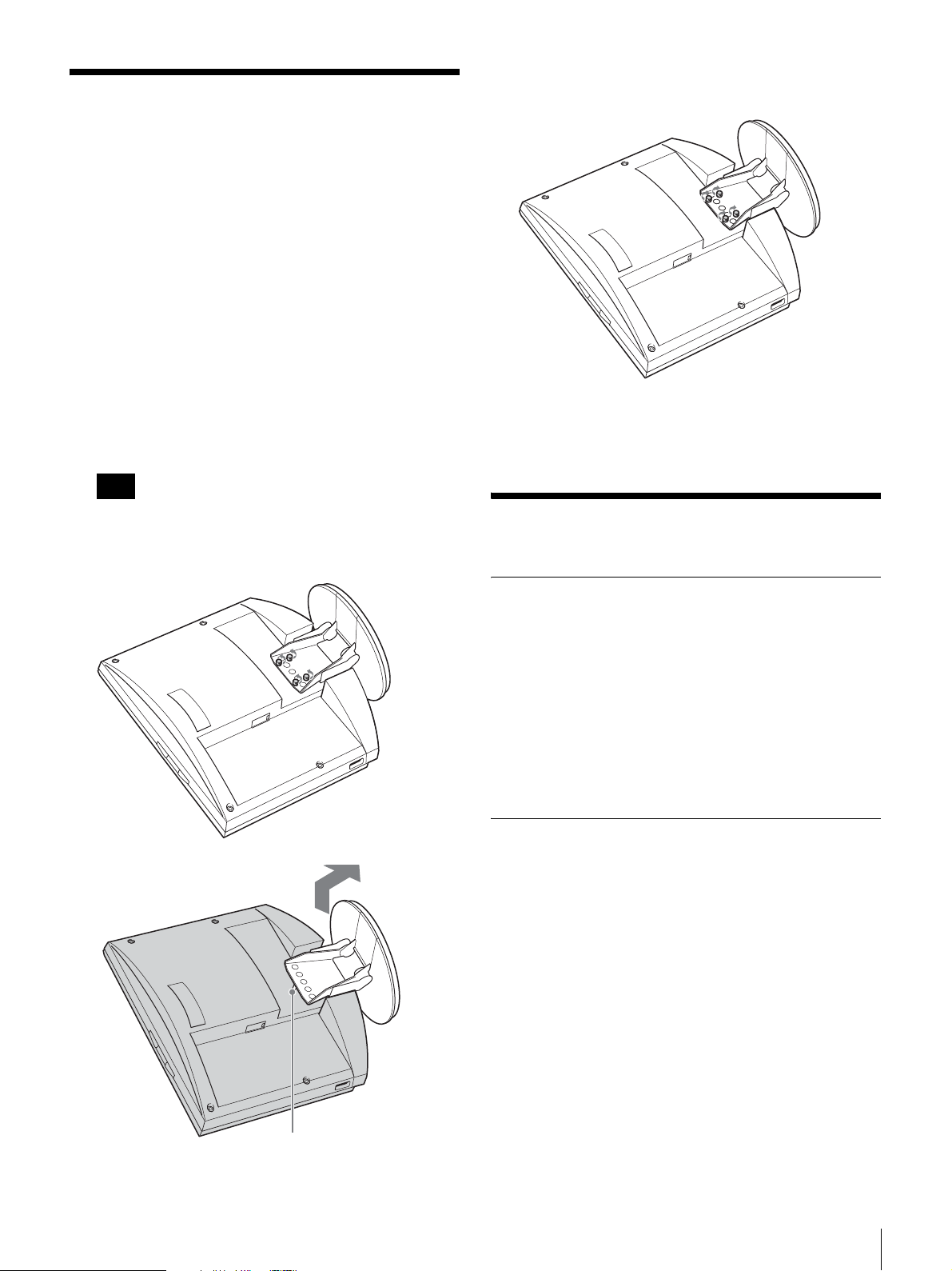
Adjusting the Height of
the Display
The stand and the display section of the PCS-TL30 are
joined by fastening screws. There are three sets of screw
holes, spaced 25 mm apart. In the factory default
condition, the display is fixed in the lowest position. By
choosing a different set of screw holes, you can change the
height of the display.
1
Remove the rear cover of the unit.
For information on how to do this, see page 26.
2
Remove the 4 screws using a coin or a similar object,
lift up the stand, and insert the positioning pin in the
hole for the new stand position.
Note
3
Tighten the 4 screws using a coin or a similar object to
secure the stand.
4
Attach the rear cover again.
Before changing the height of the display as described
above, be sure to turn the power off. Place the display
face down on a soft cloth or similar.
For Best Performance
Operating or storage location
Avoid operating or storing the system in the following
locations:
• Extremely hot or cold places
• Humid or dusty places
• Places exposed to strong vibration
• Close to sources of strong magnetism
• Close to sources of powerful electromagnetic radiation,
such as radio or TV transmitters
• Places with high interference
LCD screen
• Do not expose the LCD screen surface to the sun. Doing
so may damage the screen surface.
• Do not push or scratch the LCD screen, or place objects
on top of the system. The image may become uneven or
the LCD panel may be damaged.
• If the system is used in a cold place, a smear may occur
in the picture or the picture may become dark. This does
not indicate a failure. These phenomena improve as the
temperature rises.
• Ghosting may occur when still pictures are displayed
continuously. It may disappear after a few moments.
• The screen and cabinet get warm when the system is in
use. This is not a malfunction.
Positioning pin
Adjusting the Height of the Display / For Best Performance
31
Page 32

LCD display panel
Although the LCD display panel is made with highprecision technology, black dots may appear or bright
points of light (red, blue, or green) may appear constantly
on the LCD screen. Color stripes and uneven brightness
may also appear when you view from specific viewing
angles. This is a structural property of the LCD panel and
is not a malfunction.
Built-in speakers
The speakers generate magnetism. To avoid damaging the
data, keep magnetic tapes and disks away from the
speakers.
Cleaning
• Before cleaning, disconnect the PCS-TL30 power cord
from the AC outlet.
• The LCD screen surface is finished with a special
coating. To remove dust from the screen surface, wipe
gently with a soft, dry cloth.
• Do not use solvents such as alcohol, benzene or thinners
as they may damage or discolor the surface finish.
• When using chemical cleaning cloths, refer to their user
precautions.
• Do not apply volatile substances such as insecticide to
the unit, or allow rubber or plastic objects to touch to the
unit for an extended time, as they may damage or
discolor the surface finish.
Encoding H.261 (ITU-T Recommendation) Annex.
D (4CIF)
H.263 (special format of this system)
Sound
Bandwidth 14 kHz (MPEG4 Audio)
7 kHz (G.722 compliant with ITU-T
Recommendation)
3.4 kHz (G.711/G.728/G.729 compliant
with ITU-T Recommendation)
Transmission rate
64 kbps, 96 kbps (MPEG4 Audio)
56 kbps, 64 kbps (G.711 compliant with
ITU-T Recommendation)
48 kbps, 56 kbps, 64 kbps (G.722
compliant with ITU-T
Recommendation)
16 kbps (G.728 compliant with ITU-T
Recommendation)
8 kbps (G.729 compliant with ITU-T
Recommendation)
Network
Multiplexing Video, audio, data
Frame format H.225.0 (compliant with ITU-T
Recommendation)
Interface LAN (100BASE-TX/10BASE-T)
LAN protocol supported
HTTP
FTP
Telnet
RTP/RTCP
TCP/UDP
IP
Specifications
PCS-TL30 Video Communication System
This unit is compliant with ITU-T Recommendations
H.323 and IETF SIP.
Motion picture
Operating bandwidth
64 kbps to 2048 kbps
Coding H.261/H.263/H.263+/H.263++/H.264
(ITU-T Recommendation)
MPEG4 Simple Profile
Picture elements
CIF: 352 pixels × 288 lines
QCIF: 176 pixels × 144 lines
Still Picture
Pixels 704 pixels × 576 lines
Remote control
Far end camera control
H.281 (compliant with ITU-T
Recommendation)
Camera
Image device 1/3.2 inch color CMOS (total effective
pixels: approx. 1.3 million)
Lens f = 2.3 mm
F = 1:2.8
Horizontal angle: approx. 88°
Vertical angle: approx. 73°
Focal distance 300 mm
Pan/tilt/zoom function
By digital processing
Auto White Balance function built-in
Frame rate 30/15 fps, automatically switched to
match ambient illumination
Display
Size 17.1-type wide
Resolution 1280 × 768 (WXGA)
Response time 13 ms or less
Contrast ratio 600 : 1
32
Specifications
Page 33

Angle of view 176 degrees or more
Number of colors
16,700,000 colors
Display controller
PinP 4 corners
PandP Three windows
Input Internal: Video Communication
External RGB: Computer display
Wide mode Normal, Zoom, Wide
RGB mode 640 × 480, 800 × 600, 1024 × 768,
1280 × 768, etc.
Display of zoomed picture is possible.
Speaker
Speaker 3 W × 2
Microphone
Frequency range
14 kHz
Directional characteristic
Narrow-angle directional
Operating temperature
5°C to 35°C (41°F to 94°F)
Operating humidity
20% to 80%
Storage temperature
–20°C to +60°C (–4°F to +140°F)
Storage humidity
20% to 80% (no condensation)
Dimensions 80 × 40 × 160 mm (w/h/d) (3
3
6
/8 inches)
Mass Approx. 800 g (1 lb 12 oz)
PCS-A1 Microphone (Optional)
Bandwidth 13 kHz
Directional characteristic
Omnidirectional
Dimensions 74 ×16 × 93 mm (w/h/d)
Mass Approx. 170 g (6 oz)
Power Plug in power
21
(3 ×
/32 × 3 3/4 inches)
1
/4 × 1 5/8 ×
General
Power requirements
19.5 V
Power consumption
6.15 A
Operating temperature
5°C to 35°C (41°F to 94°F)
Operating humidity
20% to 80%
Storage temperature
–20°C to +60°C (–4°F to +140°F)
Storage humidity
20% to 80% (no condensation)
Dimensions 424 × 376 × 95.5 mm (w/h/d)
3
(16
/4 × 14 7/8 × 3 7/8 inches) (not
including the stand)
424 × 419 × 258 mm (w/h/d)
3
(16
/4 × 16 1/2 × 10 1/4 inches)
(including the stand)
Mass Approx. 8 kg (17 lb 9 oz)
Supplied accessories
Optical mouse PCS-RMU1 (1)
AC adaptor PCS-AC19V6A/PCGA-
AC19V7 (1)
Power cord (1)
CD-ROM (1)
Quick Start Guide (1)
Warranty booklet (1)
PCS-AC19V6A or PCGA-AC19V7 AC
Adaptor
Power requirements
100 to 240 V AC, 50/60 Hz, 1.8 A
Output 19.5 V, 6.15A
PCSA-A3 Microphone (Optional)
Bandwidth 13 kHz
Directional characteristic
Unidirectional
Dimension 68 × 16 × 96 mm (w/h/d)
3
(2
/4 × 21/32 × 3 7/8 inches)
Mass Approx. 200 g (7 oz)
Power Plug in power
Data Solution Module PCSA-DSM1
(Optional)
Power consumption
20 W max.
Operating temperature
5°C to 35°C (41°F to 94°F)
Operating humidity
20% to 80%
Storage temperature
–20°C to +60°C (–4°F to +140°F)
Storage humidity
20% to 80% (no condensation)
Dimensions 107 × 250 × 34 mm (w/h/d)
Mass Approx. 550 g (1 lb 3 oz)
Supplied accessories
1
(4
/4 × 9 7/8 × 1 3/8 inches) (not
including the projected parts)
Quick Start Guide (1)
Warranty booklet (1)
Specifications
33
Page 34
PCSA-SP1 SIP Software (Optional)
Supplied accessories
Serial Number seal (1)
Operating Instructions (1)
Design and specifications are subject to change without
notice.
The echo canceller of the Unit has been developed under
license from Nippon Telegraph and Telephone
Corporation. The Nippon Telegraph and Telephone
Corporation also holds the copyright of the echo
canceller software.
You may not use or sell the technologies used in the Unit
in whole or in part for weapons or making weapons. All
rights to software incorporated in the Unit and copies of
relevant documentation belong to Nippon Telegraph and
Telephone Corporation and Sony. You may not copy,
reverse engineer, decompile, disassemble, or modify the
technologies incorporated in the Unit.
This product uses Ricoh bitmap fonts produced and
marketed by Ricoh Co., Ltd.
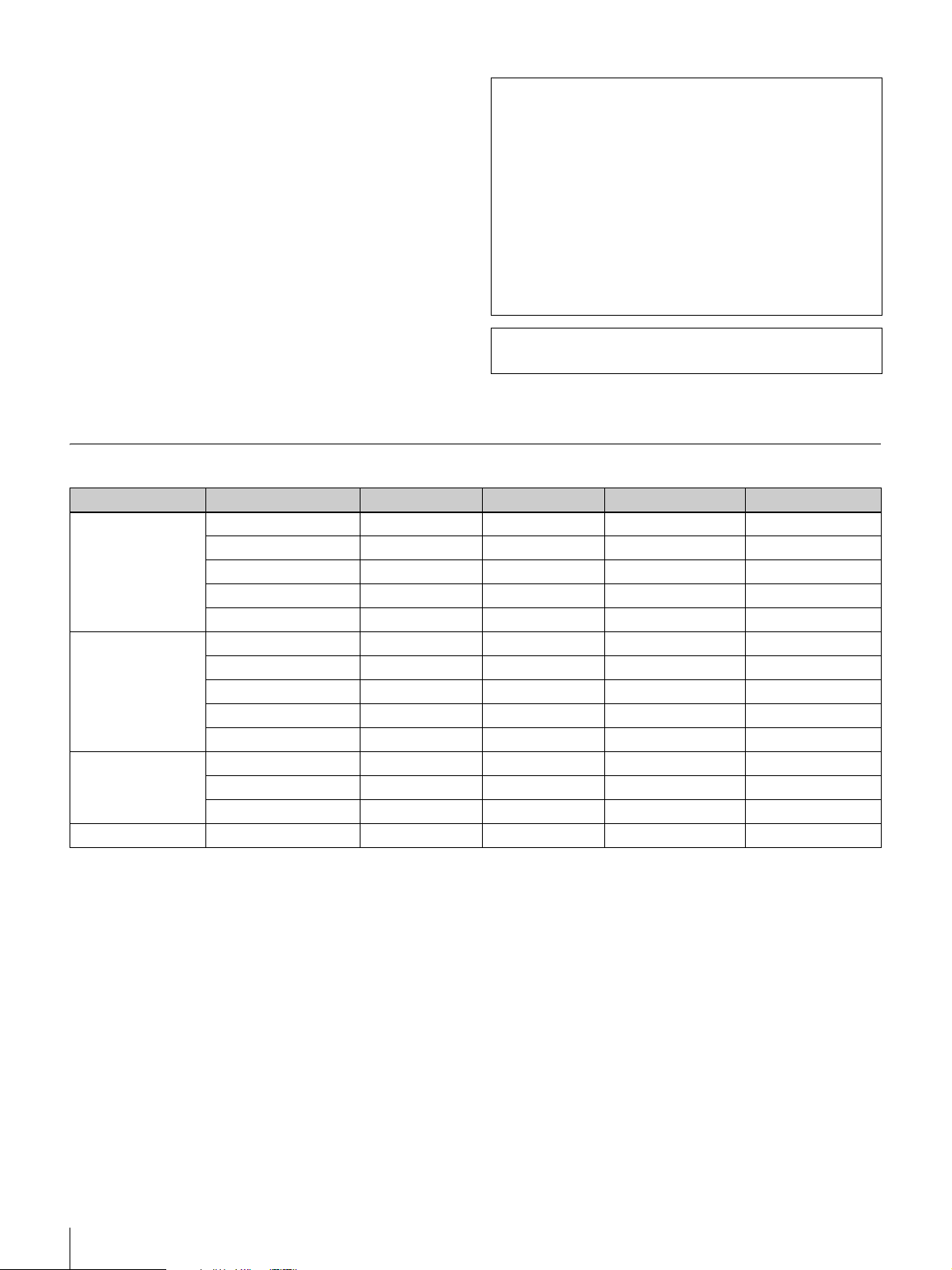
RGB input/output specifications
Picture element Signal format fH (kHz) fV (Hz) Dot clock (MHz) Sync
640 × 480 VGA mode 31.469 59.94 25.17 H-neg V-neg
Macintosh 13" 35 66.667 30.24 H-neg V-neg
VGA VESA 72 Hz 37.861 72.809 31.5 H-neg V-neg
VGA VESA 75 Hz 37.5 75 31.5 H-neg V-neg
VGA VESA 85 Hz 43.269 85.008 36 H-neg V-neg
800 × 600 SVGA VESA 56 Hz 35.156 56.25 36 H-pos V-pos
SVGA VESA 60 Hz 37.879 60.317 40 H-pos V-pos
SVGA VESA 72 Hz 48.077 72.188 50 H-pos V-pos
SVGA VESA 75 Hz 46.875 75 49.5 H-pos V-pos
SVGA VESA 85 Hz 53.674 85.061 56.25 H-pos V-pos
1024 × 768 XGA VESA 60 Hz 48.363 60.004 65 H-neg V-neg
XGA VESA 70 Hz 56.476 70.069 75 H-neg V-neg
XGA VESA 75 Hz 60.023 75.029 78.75 H-pos V-pos
1280 × 768 WXGA VESA 60 Hz* 47.693 59.992 80.12 H-neg V-pos
* Cannot be transmitted via the Data Solution Module PCSA-DSM1.
34
Specifications
Page 35

Français
AVERTISSEMENT
Afin de réduire le risque d’incendie ou
d’électrocution, ne pas exposer cet
appareil à la pluie ou à l’humidité.
Afin d’écarter tout risque d’électrocution,
garder le coffret fermé. Ne confier
l’entretien de l’appareil qu’à un technicien
qualifié.
AVERTISSEMENT
Utilisez l’adaptateur d’alimentation CA fourni avec
l’appareil en tant que source d’alimentation électrique.
L’un des adaptateurs d’alimentation CA figurant dans la
liste est fourni.
Fabricant Nº de type
Sony PCS-AC19V6A
Sony PCGA-AC19V7
Une source d’alimentation différente peut s’avérer
dangereuse et présenter, par exemple, un risque
d’incendie.
Le dispositif de coupure de l’appareil est la fiche secteur de
l’adaptateur CA.
La fiche secteur de cet appareil doit être utilisée pour
couper l’alimentation secteur.
Veuillez vous assurer que la prise est installée à proximité
de l’appareil et qu’elle est facilement accessible.
En cas d’anomalie, débranchez la fiche secteur.
AVIS
Utilisez l’ensemble de cordon d’alimentation approuvé par
l’organisme de test approprié pour les pays spécifiques où
l’appareil est utilisé.
AVERTISSEMENT concernant le port LAN
Pour des raisons de sécurité, ne connectez pas le port LAN
à un périphérique réseau dont la tension risque d’être
excessive.
Pour les utilisateurs en Europe
Avertissement
Il s’agit d’un produit Classe A. Dans un environnement
domestique, cet appareil peut provoquer des interférences
radio, dans ce cas l’utilisateur peut être amené à prendre
des mesures appropriées.
Si des interférences se produisent, contactez votre service
après-vente agréé Sony.
FR
Pour les utilisateurs au Canada
Cet appareil numérique de la classe A est conforme à la
norme NMB-003 du Canada.
35
Page 36

Table des matières
Documents fournis....................................37
Caractéristiques ........................................37
Système de communication vidéo déplaçable
intégré................................................ 37
Interface utilisateur intuitive....................... 38
Utilisation en tant qu’écran d’ordinateur.... 38
Vérification du contenu de l’emballage...38
Nomenclature et fonctions.......................39
Nomenclature des témoins.......................... 40
Connexions de système ...........................41
A propos des connecteurs ........................... 41
Précautions de connexion ........................... 41
Exemple de connexion
(utilisation autonome) ....................... 42
Exemple de connexion pour utilisation avec
ordinateur (souris séparée) ................ 42
Exemple de connexion pour utilisation avec
ordinateur (souris partagée)............... 42
Mise sous/hors tension du système........43
Ouverture du cache d’objectif .................... 43
Mise sous tension du système..................... 43
Assistant de configuration initiale .............. 44
Mise hors tension du système..................... 44
Réglage du système de communication vidéo
en mode veille ................................... 44
Commuter entre l’écran de
vidéoconférence et l’écran
d’ordinateur.........................................45
Réglage de la hauteur de l’écran .............46
Pour un meilleur fonctionnement............46
Emplacement de fonctionnement ou de
stockage............................................. 46
Ecran LCD.................................................. 47
Panneau d’affichage LCD........................... 47
Haut-parleurs intégrés................................. 47
Nettoyage.................................................... 47
Spécifications............................................47
Spécifications d’entrée/sortie RGB ............ 49
Ce guide de démarrage rapide fournit des précautions
importantes et des instructions de manipulation pour
éviter tout accident ou toute blessure. Pour vous assurer
d’un bon fonctionnement du produit, lisez ce guide
attentivement et conservez-le pour le consulter
ultérieurement.
Consultez aussi le mode d’emploi enregistré sur le CDROM fourni pour de plus amples informations sur ce
produit. Vous devez consulter ce document et le guide de
démarrage rapide.
36
Table des matières
Page 37

Documents fournis
Ce produit est fourni avec un certain nombre de
documents, comme suit. Consultez le(s) document(s) qui
répond(ent) à vos besoins.
Guide de démarrage rapide (le présent
document)
Donne des informations de base sur les réglages initiaux et
les raccordements du système. (Le CD-ROM fourni
contient aussi un fichier identique Guide de démarrage
rapide.)
Mode d’emploi (sur le CD-ROM fourni)
Fournit des instructions détaillées sur les procédures de
fonctionnement et les réglages nécessaires pour effectuer
une vidéoconférence. Ce document couvre toutes les
fonctions de ce produit.
Fonctionnement du CD-ROM
Le système suivant est nécessaire au fonctionnement du
CD-ROM.
• Ordinateur : Equipé d’un processeur Intel
- RAM : 64 Mo ou supérieur
- Lecteur CD-ROM : Vitesse
• Ecran : Résolution 800
• Système d’exploitation : Microsoft
Professionnel ou Windows XP Edition Familiale
Sans ces conditions, le fonctionnement du CD-ROM
peut être lent ou impossible.
×8 ou supérieur
× 600 ou supérieur
Préparations
Pour accéder au mode d’emploi sur le CD-ROM fourni,
vous devez avoir installé un des logiciels suivants sur votre
ordinateur :
• Adobe
• Adobe Reader 6.0 ou supérieur
Remarque
®
Acrobat® Reader 4.0 ou supérieur
®
Pentium
®
Windows® XP
®
Visionner le mode d’emploi
1
Insérez le CD-ROM fourni (intitulé « Manuals for
Video Communication System ») dans le lecteur CDROM de votre ordinateur.
Après un moment, une liste du contenu du CD-ROM
apparaît.
2
Double-cliquez sur le fichier PDF appelé « Français ».
Adobe Reader sera lancé et la première page du mode
d’emploi du système de communication vidéo sera
affiché sur l’écran.
En cliquant sur un élément de la section « Contenu »,
vous pouvez accéder directement à la page souhaitée.
• Adobe et Acrobat Reader sont des marques commerciales d’Adobe
System Incorporated.
• Microsoft et Windows sont des marques commerciales déposées de
Microsoft Corporation aux Etats-Unis et dans d’autres pays.
• Intel et Pentium sont des marques commerciales ou des marques
commerciales déposées de Intel Corporation ou de ses filiales aux EtatsUnis et dans d’autres pays.
• « IPELA » et sont des marques commerciales de Sony
Corporation.
Caractéristiques
Le système PCS-TL30 de communication vidéo est un
système de vidéoconférence qui permet de communiquer
naturellement et face à face avec un interlocuteur éloigné,
grâce à l’envoi et a la réception d’images et de son par
réseau. L’interlocuteur peut être situé n’importe où, même
à l’étranger.
Système de communication vidéo
déplaçable intégré
Si Adobe Reader n’est pas installé, vous pouvez le
télécharger sur le site suivant :
http://www.adobe.com
Tous les éléments nécessaires au système de
communication vidéo, dont la caméra, le moniteur, le
codec, les microphones et les haut-parleurs, sont intégrés
dans un seul coffret compact. Ceci garantit une portabilité
facile et vous permet de communiquer par
vidéoconférence de presque partout.
L’écran intégré de type 17 prend en charge le mode large,
et la caméra intégrée est équipée d’un mouvement de
panoramique/inclinaison numérique et d’un zoom.
Documents fournis / Caractéristiques
37
Page 38
Interface utilisateur intuitive
L’interface utilisateur est de type recouvrement, et vous
permet de contrôler les opérations à l’aide d’un simple clic
de la souris fournie. Il y a également un guide d’utilisateur
sous forme de messages et d’assistance en ligne.
Utilisation en tant qu’écran
d’ordinateur
Outre l’utilisation en mode autonome, il est aussi possible
de raccorder le PCS-TL30 à un ordinateur. Dans ce cas,
vous pouvez utiliser des souris différentes pour
l’ordinateur et le PCS-TL30, ou une seule souris pour les
deux.
Le module disponible séparément PCSA-DSM1 vous
permet de transmettre le contenu de l’affichage de l’écran
d’ordinateur vers l’écran de l’interlocuteur lors d’une
vidéoconférence.
Vérification du contenu
de l’emballage
Une fois l’appareil déballé, assurez-vous de la présence de
tous les éléments :
• PCS-TL30 unité principale (1)
Utilisation
autonome
Utilisation avec
ordinateur et
dispositifs de
pointage séparés
Utilisation avec
ordinateur et
dispositif de
pointage unique
• Souris numérique PCS-RMU1 (1)
• Adaptateur CA PCS-AC19V6A ou PCGA-AC19V7 (1)
• Cordon d’alimentation (1)
• Guide de démarrage rapide (le présent document) (1)
• CD-ROM (Mode d’emploi) (1)
• Certificat de garantie (1)
38
Vérification du contenu de l’emballage
Remarque
Le CD-ROM fourni contient le mode d’emploi, qui donne
des informations détaillées sur les procédures de
fonctionnement et tous les réglages. Ces documents sont
fournis sous forme de fichiers au format PDF.
Page 39
Nomenclature et
1 423
fonctions
Vue avant
5
6
7
8
9
q;
qa
qs
qd
qf
qg
j Bouton témoin de désactivation du microphone
Pour la suppression de son du système local. Appuyez à
nouveau sur le bouton pour rétablir l’envoi du son vers le
système à distance.
k Bouton témoin (vidéoconférence)
Pour commuter entre l’écran d’ordinateur et l’écran de
vidéoconférence.
l Bouton témoin (PC)
Pour commuter vers l’écran d’ordinateur.
m Bouton (Menu)
Appuyez sur ce bouton pour accéder au menu de
configuration.
n Interrupteur témoin (Alimentation)
Pour mettre le système sous et hors tension.
Si vous utilisez le système en écran d’ordinateur en mode
PC, une seule pression de cet interrupteur met le système
hors tension.
Si vous utilisez le système en mode VC, une seule pression
de cet interrupteur met le système en veille. Pour mettre le
système hors tension en mode VC, appuyez à nouveau sur
l’interrupteur dans les 5 secondes qui suivent.
a Signal lumineux (Tally)
S’allume quand une vidéo locale est envoyée au système à
distance.
b Objectif
c Manette pour cache d’objectif
d Microphone
e Boutons (Volume)
Pour le réglage du volume.
+ : Augmente le volume.
- : Diminue le volume.
f Prise (écouteurs) (miniprise stéréo)
Pour le raccordement d’écouteurs (disponible dans le
commerce).
g Prise (micro) (miniprise)
Pour le raccord d’un microphone PCS-A1 ou PCSA-A3
optionnel.
Remarque
L’interrupteur d’alimentation ne fonctionne pas pendant
une communication.
o Témoin « Memory Stick »
Pour voir l’état de l’emplacement du « Memory Stick ».
Remarque
Ne retirez pas le « Memory Stick » quand ce témoin est
allumé.
Vue arrière
1
h Haut-parleurs
i Lampe témoin de connexion
Montre surtout l’état des appels reçus/émis.
Nomenclature et fonctions
39
Page 40
a Capot arrière
7653421
Retirez ce capot pour accéder au panneau de contrôle. La
section de raccordement entre le support et l’écran est
aussi derrière le panneau. Vous pouvez ajuster la hauteur
de l’écran en changeant la position des vis.
Vue du coté droit
1
a Emplacement pour « Memory Stick »
Vous pouvez introduire un « Memory Stick » ici.
Panneau de connexions
(section derrière le capot arrière, vue d’en
bas)
a Connecteur CC 19,5 V
Raccordez ici l’adapteur CA fourni PCS-AC19V6A ou
PCGA-AC19V7.
b Prise AUDIO IN (entrée de son de PC) (miniprise
stéréo)
Raccordez cette prise avec la prise de sortie audio de
l’ordinateur raccordé au connecteur RGB IN.
c Connecteur RGB IN (connecteur mini D-sub 15
broches)
Raccordez ici la sortie RGB d’un ordinateur.
d Port 100BASE-TX/10BASE-T (RJ-45)
Utilisez un câble de catégorie 5 LAN pour raccorder ce
port à un multiport ou un dispositif similaire.
Ce port est équipé d’un témoin Lien/Données (vert) et d’un
témoin 100/10 Mbits/s (orange).
e Port PC
Utilisez ce connecteur quand vous voulez utiliser la même
souris pour le PCS-TL30 et pour l’ordinateur raccordé au
connecteur RGB IN. Reliez le connecteur à un port USB
de l’ordinateur.
Remarque
N’utilisez pas de câble USB d’une longueur supérieure à
3 m (9,84 pieds).
f Port RS-232C (connecteur D-sub 9 broches)
Ce connecteur sert uniquement à l’entretien du système.
g Port souris
Raccordez ici la souris numérique PCS-RMU1 fournie.
Nomenclature des témoins
Tém oin Etat Signification
Consommation
(
En ligne * Clignotant bleu
(PC) *
(Vidéoconférence)
(Microphone
désactivé) *
(« Memory Stick »)
Allumé en vert Sous tension
) *
Allumé en orange Mode veille
Clignotant
orange (cycle de
1 seconde)
Pas de témoin Hors tension
(3 fois par
seconde)
Allumé en bleu Communication en
Clignotant bleu
intermittent
Pas de témoin Off-line (aucun appel
Allumé en bleu Ecran d’ordinateur
Allumé en blanc Ecran de
Pas de témoin Mode veille
Allumé en bleu Ecran de
*
Allumé en blanc Ecran d’ordinateur
Pas de témoin Mode veille
Allumé en orange Microphone
Allumé en blanc Microphone allumé
Pas de témoin Mode veille
Allumé en orange
Pas de témoin Pas d’accès au
Anomalie du
ventilateur
Envoi/réception
cours
Témoin d’appel
manqué
manqué) ou en veille
vidéoconférence
vidéoconférence
désactivé
Accès au « Memory
Stick »
«Memory Stick»
40
Nomenclature et fonctions
Page 41
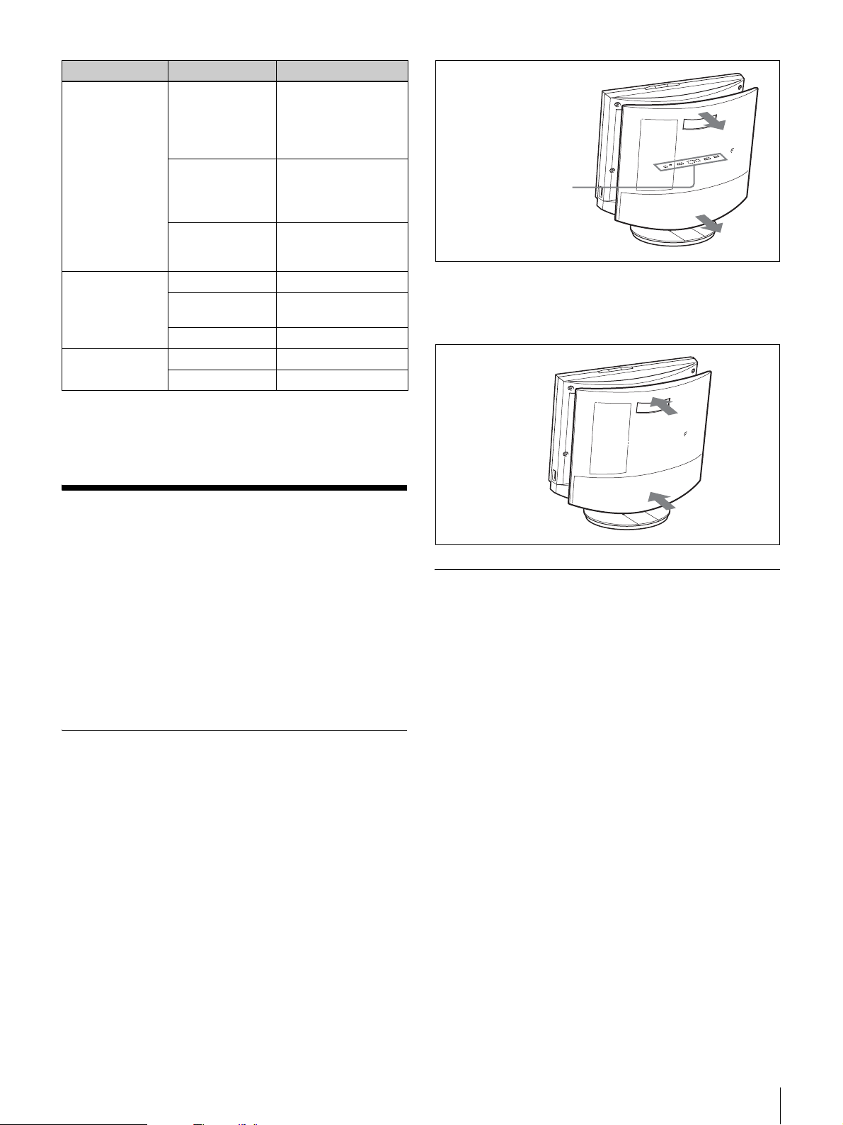
Tém oin Etat Signification
Signal lumineux
(Tally)
Lien/Données Allumé en vert Le lien est établi
100/10 Mbits/s Allumé en orange 100 Mbits/s
* Le voyant s’allume lors de la mise en route du système. Si une température
anormale est détectée, le voyant clignote et le système se met hors tension.
Allumé en orange Des images de
caméra sont
transmises à
l’interlocuteur (cache
d’objectif)
Clignotant
orange
(cycles de 5
secondes)
Pas de témoin Aucune image de
Clignotant vert Des données sont
Pas de témoin Le lien est off-line
Pas de témoin 10 Mbits/s
Des images aveugles
sont transmises à
l’interlocuteur (cache
d’objectif fermé)
caméra n’est
transmise
transmises
Panneau de connecteurs
(sous le capot arrière)
Pour remettre en place le capot arrière
Poussez sur le capot en l’alignant avec les quatre souches.
Connexions de système
Cette section montre quelques exemples représentatifs de
connexions de système.
Outre l’utilisation en mode autonome, il est aussi possible
de raccorder le PCS-TL30 à un ordinateur pour une
utilisation en écran quand aucune vidéoconférence n’est en
cours. Dans ce cas, vous pouvez utiliser des souris
différentes pour l’ordinateur et le PCS-TL30, ou raccorder
le PCS-TL30 et l’ordinateur à l’aide d’un câble USB et
utiliser la même souris pour les deux.
A propos des connecteurs
Les connecteurs du système sont situés sous le capot
arrière. Retirez le capot pour effectuer les connexions, puis
replacez-le.
Pour retirer le capot arrière
Tirez le capot vers vous.
Précautions de connexion
Avertissement
• Utilisez uniquement l’adaptateur CA et le cordon
d’alimentation fournis.
• Lors du raccordement du cordon d’alimentation de
l’adaptateur CA et du câble CC, introduisez les prises à
fond et fermement.
• Pour votre sécurité, ne raccordez pas le connecteur
100BASE-TX/10BASE-T à un réseau où une tension
excessive est possible.
Attention
• Avant d’effectuer tout raccordement, veillez à mettre
toutes les composantes hors tension.
• Pour éviter tout endommagement de l’appareil, ne
branchez ni de débranchez aucun câble si l’appareil est
sous tension.
Connexions de système
41
Page 42
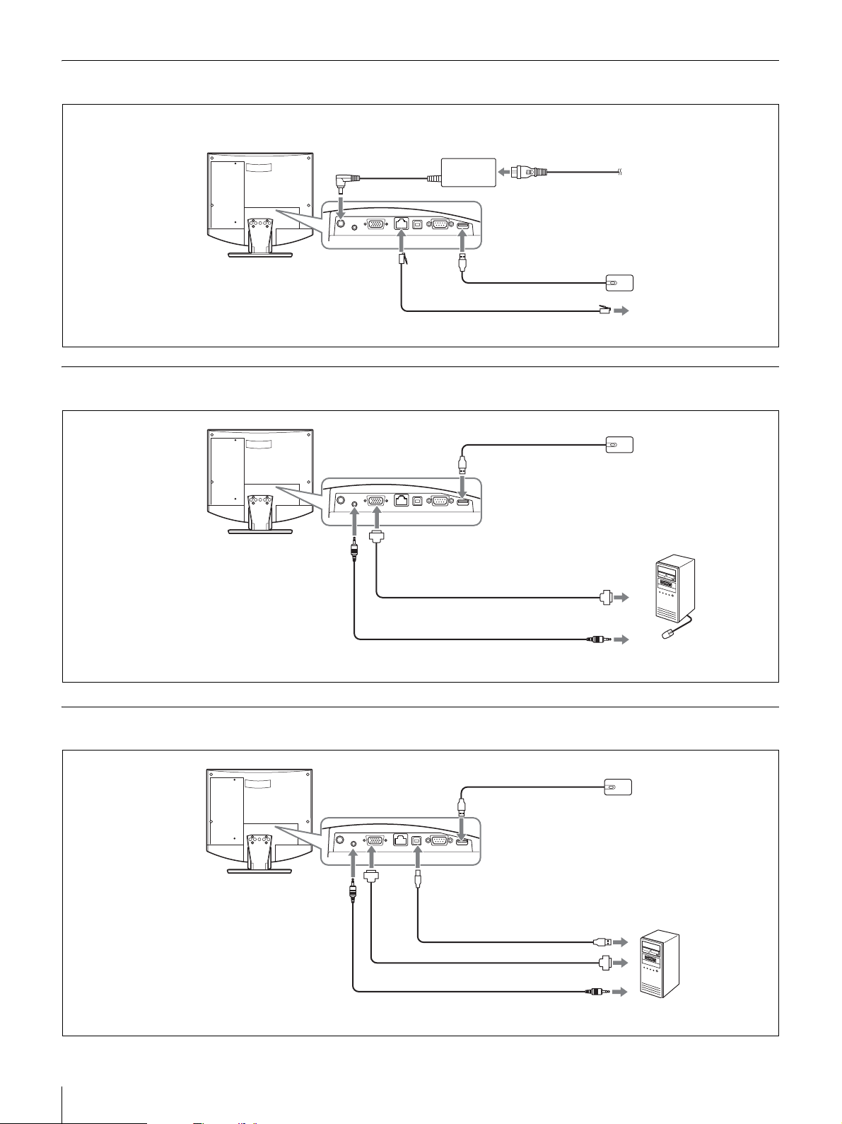
Exemple de connexion (utilisation autonome)
Effectuez les connexions dans l’ordre 1 - 5.
3 Vers le connecteur
CC19,5 V
Système de
communication vidéo
PCS-TL30
Vers 100BASE-TX/ 2
Port 10BASE-T
Adaptateur CA PCS-AC19V6A
ou PCGA-AC19V7
(fourni)
1 Vers le port souris
Câble UTP de catégorie 5 (câble droit, disponible dans le commerce)
4 Cordon d’alimentation (fourni)
5 Vers la prise CA
(120 V CA)
Souris numérique PCSRMU1 (fournie)
Vers LAN
Exemple de connexion pour utilisation avec ordinateur (souris séparée)
Souris numérique
Système de
communication vidéo
PCS-TL30
Vers le port souris
PCS-RMU1 (fournie)
Vers le connecteur
Vers le connecteur RGB IN
Vers la prise AUDIO IN
Câble avec connecteur mini
D-sub 15 broches (disponible
dans le commerce)
Câble audio avec miniprise stéréo
(disponible dans le commerce)
Vers la sortie
RGB
Vers la sortie
audio
Ordinateur
Exemple de connexion pour utilisation avec ordinateur (souris partagée)
Souris numérique
Système de
communication vidéo
PCS-TL30
Vers la
prise
AUDIO IN
Vers le port souris
Vers le port PC
Vers
RGB IN
connecteur
Câble USB (disponible
dans le commerce) *
Vers le port USB
PCS-RMU1 (fournie)
42
Connexions de système
longueur supérieure à 3 m (9,84 pieds).
Câble avec connecteur mini D-sub 15
broches (disponible dans le commerce)
Câble audio avec miniprise stéréo
(disponible dans le commerce)
Vers la sortie RGB
Vers la sortie audio* N’utilisez pas de câble USB d’une
Ordinateur
Page 43
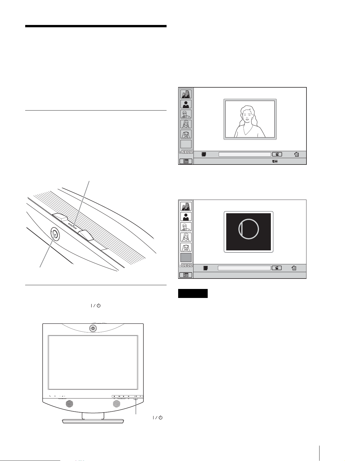
Mise sous/hors tension
du système
L’interrupteur témoin s’allume en orange et le système de
communication vidéo est sous tension. Lorsque le
moniteur est sous tension, le témoin s’allume en vert. Le
menu de démarrage s’affiche sur l’écran et l’image de la
caméra locale est aussi affichée.
Avant de mettre le système sous tension, vérifiez que les
connexions du système ont été effectuées correctement.
L’apparence de l’écran qui est montré ici peut être
différente selon la version du logiciel.
Ouverture du cache d’objectif
Le système est équipé d’un cache d’objectif servant à
cacher la caméra. Avant de commencer une
vidéoconférence, ouvrez le cache en faisant glisser vers la
droite son interrupteur situé au-dessus du système. Si le
cache d’objectif est fermé, l’image sur le site local n’est
pas visible sur le site distant.
Interrupteur de cache d’objectif
Menu de démarrage
EMPTY
Cliquez sur l’icône pour entrer dans la fonction.
Lorsque le cache d’objectif est fermé, le menu de
démarrage s’affiche de la façon suivante.
CLOSED
Number :012.345.678.912
Caméra
Mise sous tension du système
Appuyez sur l’interrupteur (Alimentation) sur le PCSTL30.
Closed
EMPTY
Cliquez sur l’icône pour entrer dans la fonction.
Remarques
Number :012.345.678.912
• La première fois que vous appuyez sur l’interrupteur
d’alimentation après avoir branché le cordon
d’alimentation dans la prise murale, l’interrupteur
témoin peut prendre jusqu’à dix secondes pour
s’allumer.
• Lorsque vous mettez le système de communication
vidéo sous tension pour la première fois après
l’installation, l’assistant de configuration s’affiche.
Configurez votre système à l’aide de l’assistant.
Interrupteur
(Alimentation)
Mise sous/hors tension du système
43
Page 44
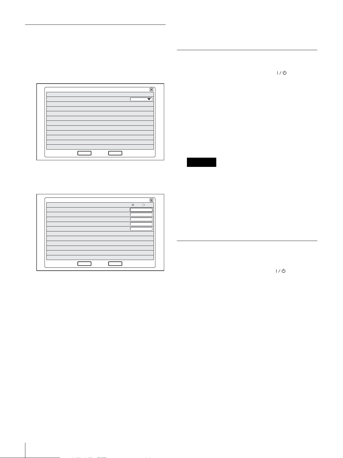
Assistant de configuration initiale
Certains réglages peuvent être légèrement différents en
fonction du logiciel d’écran.
1
Sur la liste déroulante « Language », sélectionnez la
langue à utiliser pour les menus et les messages.
1/2
Language
Next
2
Cliquez sur « Next ».
3
Effectuez les réglages LAN nécessaires.
Mode DHCP
Nom d’hôte
Adresse IP
Masque de réseau
Adresse passerelle
Adresse DNS
Cancel
English
2/2
Auto Désactivé
4
Cliquez sur « Enregistrer ».
Les réglages sont enregistrés.
Mise hors tension du système
1
Appuyez deux fois sur l’interrupteur
(Alimentation).
Après avoir appuyé une fois sur l’interrupteur, le
message « Pour entrer en mode veille, attendez
quelques instants. Pour mettre le système hors tension,
appuyez à nouveau sur l’interrupteur. » s’affiche à
l’écran. Appuyez à nouveau sur l’interrupteur
d’alimentation.
2
Pour mettre d’autres appareils utilisés pour la
vidéoconférence hors tension.
Remarques
• Mettez le système hors tension lorsque vous ne
comptez pas l’utiliser pendant longtemps. Lorsque
le système est hors tension, vous ne pouvez pas
recevoir d’appel d’un interlocuteur.
• Si vous utilisez le système en écran d’ordinateur en
mode PC, l’alimentation s’éteint par simple pression
sur l’interrupteur d’alimentation.
• Pendant une conférence, l’interrupteur
d’alimentation ne fonctionne pas.
Enregistrer Précédent
Mode DHCP : Règle le DHCP (Dynamic Host
Configuration Protocol).
Auto : Distribue automatiquement votre adresse
IP, votre masque de sous-réseau, vos adresses
passerelle et DNS.
Désactivé : Désactive le DHCP. Dans ce cas,
effectuez manuellement les réglages de votre
adresse IP, votre masque de sous-réseau, vos
adresses passerelle et DNS.
Nom d’hôte : Saisissez votre nom d’hôte.
Adresse IP : Saisissez votre adresse IP.
Masque de réseau : Saisissez votre masque de
sous-réseau.
Adresse passerelle : Saisissez votre adresse
passerelle par défaut.
Adresse DNS : Saisissez l’adresse de votre serveur
DNS (Domain Name System).
Si vous ne connaissez pas les réglages nécessaires à la
configuration LAN, contactez votre administrateur de réseau.
Réglage du système de
communication vidéo en mode veille
Lorsque vous appuyez sur l’interrupteur
(Alimentation) sur le PCS-TL30, le message « Pour entrer
en mode veille, attendez quelques instants. Pour mettre le
système hors tension, appuyez à nouveau sur
l’interrupteur. » s’affiche à l’écran. Si vous attendez
simplement, le système se mettra en mode veille.
Vous pouvez recevoir un appel d’un interlocuteur en mode
veille.
Pour revenir du mode veille au mode normal, appuyez une
fois sur l’interrupteur d’alimentation.
44
Mise sous/hors tension du système
Page 45
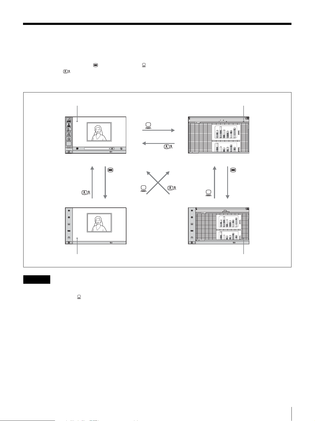
Commuter entre l’écran de vidéoconférence et l’écran
d’ordinateur
Vous pouvez utiliser le bouton (Menu), le bouton
(PC) et le bouton (Vidéoconférence) dans la partie
inférieure droite de l’appareil pour commuter entre l’écran
de vidéoconférence et l’écran d’ordinateur.
Ecran de vidéoconférence (menu de démarrage) Ecran d’ordinateur normal
ABCDEFGH IJ KLMN
1
abcd
2
EMPTY
Cliquez sur l’icône pour entrer dans la fonction.
Number :012.345.678.912
3
4
5
6
7
8
9
10
11
12
13
14
15
16
17
18
19
20
21
22
23
24
25
26
27
28
29
30
31
32
33
34
46
23
12
67
45
4
12
26
5
16
57
6
7
23
69
15
44
76
abcd
45
67
4
26
12
5
57
16
6
23
45
12
15
78
46
23
7
69
34
180
56
76
1
6
0
38
1
4
0
13
12
1
2
0
1
0
0
6
0
5
0
4
0
2
0
0
1
2
180
1
6
0
56
1
4
0
76
23
1
2
0
34
1
0
0
12
13
0
6
5
0
4
0
d
c
b
a
6
5
4
3
d
c
b
a
Cliquez sur l’icône pour entrer dans la fonction.
Number :012.345.678.912
Ecran de vidéoconférence (menu de configuration) Ecran d’ordinateur (menu de configuration)
Remarques
• Quand le PCS-TL30 n’est pas connecté à un ordinateur,
la pression du bouton (PC) pour commuter vers
l’écran d’ordinateur désactive la souris.
• Si une sous-image est affichée lors d’une
communication, cette sous-image reste visible même
quand vous commutez vers l’écran d’ordinateur. Mais la
vidéo affichée dans la sous-image provient soit du
système à distance ou du système local.
• Lors de l’utilisation de souris différentes pour le PCSTL30 et l’ordinateur, la souris active dépend de
l’affichage d’écran en cours. Lors de l’affichage d’écran
d’ordinateur normal, la souris connectée à l’ordinateur
est active. Quand d’autres écrans sont affichés, la souris
connectée au PCS-TL30 est active.
ABCDEFGH IJ KLMN
1
2
abcd
3
12
46
23
34
4
4
5
5
6
6
7
69
8
44
9
10
11
12
13
14
15
16
17
18
19
20
21
22
23
24
25
abcd
26
4
27
5
28
6
29
12
30
46
31
69
32
33
34
Cliquez sur l’icône pour entrer dans la fonction.
180
67
45
56
12
26
76
1
6
0
16
57
38
4
0
1
7
23
13
76
15
12
2
0
1
0
1
0
6
0
5
0
0
4
0
2
0
1
2
180
6
0
1
67
45
56
4
0
1
12
26
76
16
57
23
2
0
1
45
23
34
0
0
1
78
15
12
7
23
13
6
0
5
0
4
0
3
5
4
d
c
b
a
6
d
c
b
a
Number :012.345.678.912
Commuter entre l’écran de vidéoconférence et l’écran d’ordinateur
45
Page 46
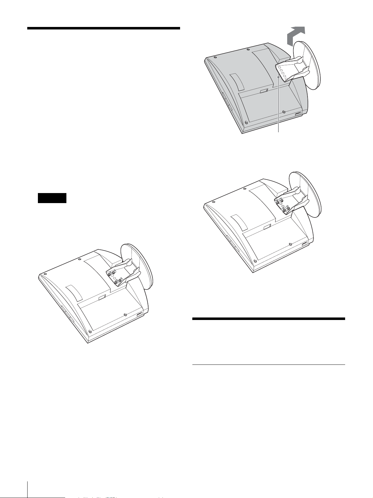
Réglage de la hauteur de
l’écran
Le support et l’écran du PCS-TL30 sont joints par une
fermeture à vis. Il y a trois positions d’orifices de vis, à 25
mm d’intervalle. La position d’usine par défaut de l’écran
est la position la plus basse. En choisissant d’autres
positions de trous de vis, vous pouvez changer la hauteur
de l’écran.
1
Retirez le capot arrière de l’appareil.
Pour des informations sur cette étape, voir page 41.
2
Enlevez les 4 vis à l’aide d’une pièce de monnaie ou
d’un objet similaire, soulevez le support et introduisez
la broche de positionnement dans l’orifice pour la
nouvelle position du support.
Remarque
Avant de changer la hauteur de l’écran comme cidessus, veillez à mettre l’appareil hors tension. Placez
l’écran avec sa face vers le bas sur un chiffon doux ou
similaire.
Broche de positionnement
3
Replacez les 4 vis à l’aide d’une pièce de monnaie ou
d’un objet similaire pour fixer le support.
4
Replacez le capot arrière.
Pour un meilleur
fonctionnement
Emplacement de fonctionnement ou
de stockage
Evitez de faire fonctionner ou de stocker le système dans
les endroits suivants :
• Endroits très chauds ou très froids
• Endroits humides ou poussiéreux
• Endroits exposés à une forte vibration
• Près de sources de fort magnétisme
• Près de sources de radiation électromagnétique
puissante, telles que des transmetteurs radio ou TV
• Endroits à forte interférence
46
Réglage de la hauteur de l’écran / Pour un meilleur fonctionnement
Page 47

Ecran LCD
• N’exposez pas la surface de l’écran LCD au soleil. Vous
risquez de l’endommager.
• Ne poussez ni n’égratignez pas l’écran LCD. Ne placez
aucun objet au-dessus du système. L’image risque de
devenir irrégulière ou l’écran LCD risque d’être
endommagé.
• Si vous utilisez le système dans un endroit froid, une
tache risque d’apparaître sur l’image ou l’image risque
de devenir foncée. Ceci n’est pas un problème. Ces
phénomènes s’améliorent au fur et à mesure que la
température augmente.
• Des ombres risquent d’apparaître lorsque vous affichez
des images fixes en continu. Elles peuvent disparaître au
bout d’un moment.
• L’écran et l’armoire deviennent chauds lorsque vous
utilisez le système. Il ne s’agit pas d’une anomalie.
Panneau d’affichage LCD
Même si le panneau d’affichage LCD est fabriqué avec
une technologie de haute précision, des points noirs ou des
points brillants de lumière (rouge, bleu ou vert) peuvent
apparaître en permanence sur l’écran LCD. Des bandes de
couleur et un contraste irrégulier peuvent également
apparaître lorsque vous visualisez à partir d’angles
spécifiques. Il s’agit d’une propriété structurelle du
panneau LCD. Il ne s’agit pas d’une anomalie.
Haut-parleurs intégrés
Les haut-parleurs génèrent du magnétisme. Pour éviter
d’endommager les données, conservez les bandes
magnétiques et les disques loin des haut-parleurs.
Nettoyage
• Avant le nettoyage, débranchez le cordon d’alimentation
du PCS-TL30 de la prise de courant alternatif.
• La surface de l’écran LCD est protégée par un film
spécial. Pour enlever la poussière de la surface de
l’écran, utilisez un chiffon sec et doux.
• N’utilisez pas de solvants tels que l’alcool, le benzène ou
des diluants car ils risquent d’abîmer ou de décolorer le
revêtement de la surface.
• Lors de l’utilisation de chiffons de nettoyage avec
produits chimiques, suivez leurs précautions.
• N’appliquez pas de substances volatiles telles que des
insecticides sur l’écran et ne le mettez pas en contact
avec des objets en caoutchouc ou en plastique pendant
longtemps car ils risquent d’abîmer ou de décolorer le
revêtement de la surface.
Spécifications
PCS-TL30 Système de communication
vidéo
Cet appareil est conforme aux recommandations ITU-T
H.323 et IETF SIP.
Images animées
Bande passante de fonctionnement
64 kbps à 2048 kbps
Codage H.261/H.263/H.263+/H.263++/H.264
(recommandation ITU-T)
MPEG4 Simple Profile
Eléments d’image
CIF : 352 pixels × 288 lignes
QCIF : 176 pixels × 144 lignes
Images fixes
Pixels 704 pixels × 576 lignes
Codage H.261 (recommandation ITU-T) Annexe.
D (4CIF)
H.263 (format spécial de ce système)
Son
Bande passante 14 kHz (MPEG4 Audio)
7 kHz (G.722 conforme à la
recommandation ITU-T)
3,4 kHz (G.711/G.728/G.729, conforme
à la recommandation ITU-T)
Débit de transfert
64 kbps, 96 kbps (MPEG4 Audio)
56 Kbps, 64 kbps (G.711, conforme à la
recommandation ITU-T)
48 kbps, 56 kbps, 64 kbps (G.722,
conforme à la recommandation ITUT)
16 kbps (G.728, conform e à la
recommandation ITU-T)
8 kbps (G.729 conforme à la
recommandation ITU-T)
Réseau
Multiplexage vidéo, audio, données
Format d’images
H.225.0 (conforme à la recommandation
ITU-T)
Interface LAN (100BASE-TX/10BASE-T)
Protocole LAN pris en charge
HTTP
FTP
Telnet
RTP/RTCP
TCP/UDP
IP
Spécifications
47
Page 48

Télécommande
Commande de la caméra du correspondant
H.281 (conforme à la recommandation
ITU-T)
Caméra
Dispositif d’image
1/3,2 pouces couleur CMOS (nombre
total de pixels effectifs : environ 1,3
millions)
Objectif f = 2,3 mm
F = 1:2,8
Angle horizontal : 88° environ
Angle vertical : 73° environ
Distance focale 300 mm
Fonction pan/zoom/tilt (panoramique/inclinaison/zoom)
Par traitement numérique
Fonction de Balance des blancs automatique intégrée
Fréquence d’images
30/15 fps, commute automatiquement
pour correspondre à l’éclairage
ambiant
Ecran
Taille Type 17,1 large
Résolution 1280 × 768 (WXGA)
Temps de réponse
13 ms ou moins
Rapport de contraste
600 : 1
Angle de prise de vue
176 degrés ou plus
Nombre de couleurs
16.700.000 couleurs
Contrôleur d’écran
PinP 4 coins
PandP Trois fenêtres
Entrée interne : Communication vidéo
RGB externe : Écran d’ordinateur
Mode de largeur
Normal, Zoom, Large
Mode RGB 640 × 480, 800 × 600, 1024 × 768,
1280 × 768, etc.
L’affichage d’une image agrandie est
possible.
Haut-parleur
Haut-parleur 3 W × 2
Microphone
Plage de fréquence
14 kHz
Propriétés directives
Directionnel, angle étroit
Informations générales
Alimentation 19,5 V
Consommation
6,15 A
Température d’utilisation
5°C à 35°C (41°F à 94°F)
Humidité d’utilisation
20% à 80%
Température de stockage
-20°C à +60°C (-4°F à +140°F)
Degré d’humidité pour le stockage
20% à 80% (sans condensation)
Dimensions 424 × 376 × 95,5 mm (l/h/p) (16
7
/8 × 3 7/8 pouces) (sans le support)
424 × 419 × 258 mm (l/h/p) (16
1
/2 × 10 1/4 pouces) (avec le support)
3
/4× 14
3
/4 × 16
Poids 8 kg (17 lb 9 oz) environ
Accessoires fournis
Souris numérique PCS-RMU1 (1)
Adaptateur CA PCS-AC19V6A/PCGA-
AC19V7 (1)
Cordon d’alimentation (1)
CD-ROM (1)
Guide de démarrage rapide (1)
Certificat de garantie (1)
Adaptateur CA PCS-AC19V6A ou PCGAAC19V7
Alimentation
100 V à 240 V CA, 50/60 Hz, 1,8 A
Sortie 19,5 V, 6,15 A
Température d’utilisation
5°C à 35°C (41°F à 94°F)
Humidité d’utilisation
20% à 80%
Température de stockage
-20°C à +60°C (-4°F à +140°F)
Degré d’humidité pour le stockage
20% à 80% (sans condensation)
Dimensions 80 × 40 × 160 mm (l/h/p) (3
3
6
/8 pouces)
1
/4 × 1 5/8 ×
Poids 800 g (1 lb 12 oz) environ
Microphone PCS-A1 (en option)
Bande passante 13 kHz
Propriétés directives
Omnidirectionnel
Dimensions 74 × 16 × 93 mm (l/h/p)
21
(3 ×
/32 × 3 3/4 pouces)
Poids 170 g (6 oz) environ
Alimentation Auto-alimentation
Microphone PCSA-A3 (en option)
Bande passante 13 kHz
Propriétés directives
Unidirectionnel
48
Spécifications
Page 49
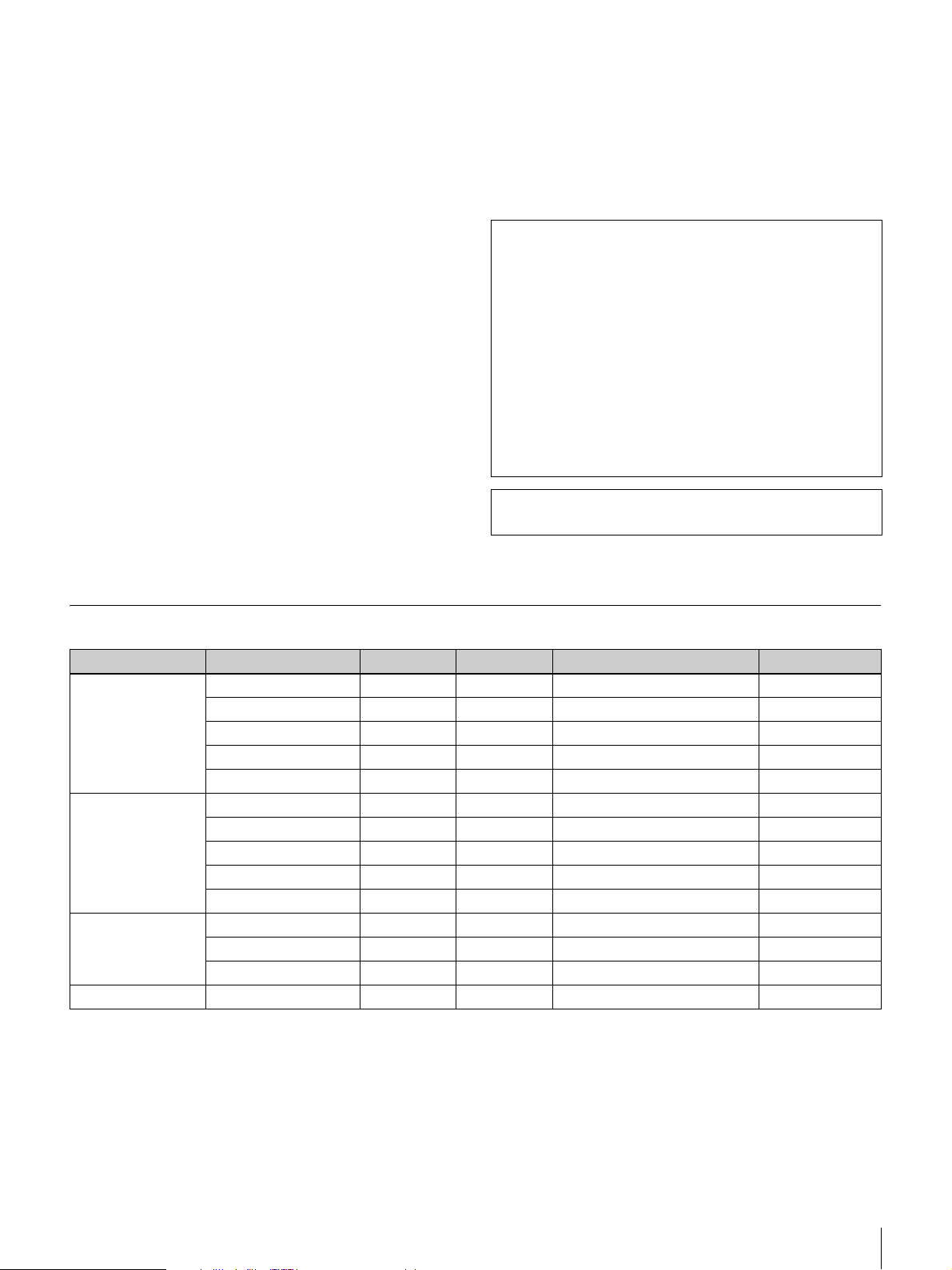
Dimensions 68 × 16 × 96 mm (l/h/p)
3
(2
/4 × 21/32 × 3 7/8 pouces)
Poids 200 g (7 oz) environ
Alimentation Auto-alimentation
Logiciel SIP PCSA-SP1 (en option)
Accessoires fournis
Etiquette de numéro de série (1)
Mode d’emploi (1)
Module Solution de données PCSA-DSM1
(en option)
Consommation
20 W max.
Température d’utilisation
5°C à 35°C (41°F à 94°F)
Humidité d’utilisation
20% à 80%
Température de stockage
-20°C à +60°C (-4°F à +140°F)
Degré d’humidité pour le stockage
20% à 80% (sans condensation)
Dimensions 107 × 250 × 34 mm (l/h/p)
1
(4
/4 × 9 7/8 × 1 3/8 pouces) (sans
compter les parties saillantes)
Poids 550 g (1 lb 3oz) environ
Accessoires fournis
Guide de démarrage rapide (1)
Certificat de garantie (1)
Spécifications d’entrée/sortie RGB
La conception et les spécifications sont susceptibles d’être
modifiées sans préavis.
L’annulateur d’écho de l’appareil a été développé sous
licence de Nippon Telegraph and Telephone Corporation.
La Nippon Telegraph and Telephone Corporation
possède aussi des droits d’auteur du logiciel d’annulation
d’écho.
Il vous est interdit d’utiliser ou de vendre tout ou une
partie des technologies de l’appareil pour des armes ou
pour fabriquer des armes. Tous droits relatifs au logiciel
intégré à l’appareil et aux copies de la documentation
associée appartiennent à la Nippon Telegraph and
Telephone Corporation et à Sony. Il vous est interdit de
copier, de démonter, de désassembler ou de modifier les
technologies comprises dans cet appareil.
Ce produit utilise les polices par point Ricoh, produites et
commercialisées par Ricoh Co., Ltd.
Elément d’image Format du signal fH (kHz) fV (Hz) Fréquence de point (MHz) Sync.
640 × 480 Mode VGA 31,469 59,94 25,17 H nég V nég
Macintosh 13" 35 66,667 30,24 H nég V nég
VGA VESA 72 Hz 37,861 72,809 31,5 H nég V nég
VGA VESA 75 Hz 37,5 75 31,5 H nég V nég
VGA VESA 85 Hz 43,269 85,008 36 H nég V nég
800 × 600 SVGA VESA 56 Hz 35,156 56,25 36 H-pos V-pos
SVGA VESA 60 Hz 37,879 60,317 40 H-pos V-pos
SVGA VESA 72 Hz 48,077 72,188 50 H-pos V-pos
SVGA VESA 75 Hz 46,875 75 49,5 H-pos V-pos
SVGA VESA 85 Hz 53,674 85,061 56,25 H-pos V-pos
1024 × 768 XGA VESA 60 Hz 48,363 60,004 65 H nég V nég
XGA VESA 70 Hz 56,476 70,069 75 H nég V nég
XGA VESA 75 Hz 60,023 75,029 78,75 H-pos V-pos
1280 × 768 WXGA VESA 60 Hz* 47,693 59,992 80,12 H-nég V-pos
* Pas de transmission possible via le Module de solution de données PCSA-DSM1.
Spécifications
49
Page 50

Deutsch
VORSICHT
Schützen Sie das Gerät vor Regen und
Feuchtigkeit. Andernfalls besteht die
Gefahr von Bränden und elektrischen
Schlägen.
Um einen elektrischen Schlag zu
vermeiden, darf das Gehäuse nicht
geöffnet werden.
Überlassen Sie Wartungsarbeiten stets nur
einem Fachmann.
WARNUNG
Verwenden Sie ausschließlich das mitgelieferte Netzteil
zur Stromversorgung.
Eines der nachfolgend aufgeführten Netzteile wird
mitgeliefert.
Hersteller Typ-Nr.
Sony PCS-AC19V6A
Sony PCGA-AC19V7
Für Kunden in Deutschland
Diese Ausrüstung erfüllt die Europäischen EMCBestimmungen für die Verwendung in folgender/
folgenden Umgebung (en):
- Gewerbegebiete
- Leichtindustriegebiete
(Diese Ausrüstung erfüllt die Bestimmungen der Norm
EN55022, Klasse A.)
Dieses Gerät ist nur für den Gebrauch in Gewerbe und
Leichtindustrie bestimmt.
Sollten Funkstörungen auftreten, wenden Sie sich bitte an
den nächsten autorisierten Sony-Kundendienst.
Bei Verwendung anderer Netzteile bestehen Brand- und
anderen Gefahren.
Um das Gerät vom Stromnetz zu trennen, ziehen Sie den
Stecker des Netzteils aus der Steckdose.
Stellen Sie sicher, dass das Gerät in der Nähe einer leicht
zugänglichen Steckdose installiert wird.
Bei unnormalem Betriebsverhalten ziehen Sie den Stecker
des Netzteils aus der Steckdose.
HINWEIS
Verwenden Sie nur das Netzkabel, welches für den
Einsatzort von der entsprechend zuständigen Prüfstelle
zugelassen ist.
WARNHINWEIS zum Anschluss LAN
Schließen Sie aus Sicherheitsgründen an den Anschluss
LAN keine Netzwerkgeräte an, die hohe Spannungen
führen könnten.
Für Kunden in Europa
Warnung
Dies ist eine Einrichtung, welche die Funk- Entstörung
nach Klasse A besitzt. Diese Einrichtung kann im
Wohnbereich Funkstörungen verursachen; in diesem Fall
kann vom Betreiber verlangt werden, angemessene
Maßnahmen durchzuführen und dafür aufzukommen.
50
Page 51
Inhaltsverzeichnis
Umfang der Dokumentation .....................52
Produkteigenschaften...............................52
Integriertes tragbares
Videokommunikationssystem........... 52
Intuitive Benutzeroberfläche ...................... 53
Verwenden als Computermonitor............... 53
Überprüfen des Packungsinhalts ............53
Namen und Funktionen der Teile.............54
Namen und Funktionen der LEDs .............. 55
Systemanschlüsse....................................56
Hinweis zu den Anschlüssen ...................... 56
Sicherheitshinweise für die Verbindungen. 56
Anschlussbeispiel (Verwendung als
selbstständiges Gerät)........................ 57
Anschlussbeispiel für die Verwendung mit
einem Computer (separate Maus) ..... 57
Anschlussbeispiel für die Verwendung mit
einem Computer (gemeinsam genutzte
Maus)................................................. 57
Ein- und Ausschalten des Systems.........58
Öffnen der Objektivabdeckung................... 58
Einschalten des Systems............................. 58
Setup-Assistent für die Ersteinrichtung...... 59
Ausschalten des Systems ............................ 59
Aktivieren des Bereitschaftsmodus des
Videokommunikationssystems ......... 59
Umschalten zwischen
Videokonferenzmonitor und
Computermonitor ...............................60
Höheneinstellung des Monitors...............61
Hinweise für die optimale Nutzung des
Gerätes ................................................61
Betriebs- und Lagerbedingungen................ 61
LCD-Bildschirm ......................................... 62
LCD-Anzeige.............................................. 62
Integrierte Lautsprecher.............................. 62
Reinigen des Gerätes .................................. 62
Technische Daten......................................62
RGB-Eingangs- und
Ausgangsspezifikationen................... 64
Diese Kurzanleitung enthält wichtige
Sicherheitshinweise und Anweisungen zum Umgang mit
dem Gerät Produkt zur Vermeidung von Unfällen oder
Verletzungen. Lesen Sie das Dokument aufmerksam und
bewahren Sie es zum Nachschlagen auf, um einen
sicheren Betrieb des Produkts zu gewährleisten.
Beachten Sie außerdem die ausführlichen Informationen
über das Produkt in der Betriebsanleitung auf der
beiliegenden CD-ROM, die gemeinsam mit der
Kurzanleitung zu verwenden ist.
DE
Inhaltsverzeichnis
51
Page 52
Umfang der
Dokumentation
Anzeigen der Bedienungsanleitung
1
Legen Sie die mitgelieferte CD-ROM mit dem Titel
„Manuals for Video Communication System“ in das
CD-ROM-Laufwerk Ihres Computers ein.
Im Lieferumfang dieses Produkts sind die im Folgenden
aufgeführten Dokumente enthalten.
Kurzanleitung (dieses Dokument)
Enthält grundlegende Informationen über die
Grundeinstellungen und das Anschließen des Systems.
(Die beiliegende CD-ROM enthält die Kurzanleitung in
Dateiform.)
Betriebsanleitung (auf CD-ROM)
Enthält ausführliche Informationen über die Bedienung
des Gerätes und die erforderlichen Einstellungen für
verschiedene Arten von Videokonferenzen. Dieses
Dokument enthält eine Beschreibung aller Funktionen des
Produkts.
Systemanforderungen für die Benutzung
der CD-ROM
Für die Benutzung der CD-ROM müssen die folgenden
Systemanforderungen erfüllt sein.
• Computer: Intel
- RAM: Mindestens 64 MB
- CD-ROM-Laufwerk: Mindestens 8-fache
Geschwindigkeit
• Monitor: Auflösung mindestens 800
• Betriebssystem: Microsoft
oder Windows XP Home Edition
Wenn diese Anforderungen nicht erfüllt sind, kann die
CD-ROM unter Umständen nicht oder nur sehr langsam
benutzt werden.
®
Pentium®-Prozessor
®
Windows® XP Professional
× 600
Vorbereitungen
Um die Betriebsanleitung auf der beiliegenden CD-ROM
verwenden zu können, muss auf dem Computer eine der
folgenden Softwareanwendungen installiert sein:
• Adobe
• Adobe ® Reader ab Version 6.0
®
Acrobat® Reader ab Version 4.0
Nach einer kurzen Zeit wird ein Bildschirm mit dem
Inhalt der CD-ROM angezeigt.
2
Doppelklicken Sie auf die PDF-Datei mit dem Namen
„Deutsch“.
Adobe Reader wird gestartet, und die erste Seite der
Betriebsanleitung für das
Videokommunikationssystem wird auf dem
Bildschirm angezeigt.
Durch Klicken auf ein Thema im „Inhaltsverzeichnis“
können Sie direkt zu der betreffenden Seite wechseln.
• Adobe und Adobe Reader sind Warenzeichen von Adobe Systems,
Incorporated.
• Microsoft und Windows sind in den USA sowie weiteren Ländern
eingetragene Warenzeichen der Microsoft Corporation.
• Intel und Pentium sind in den USA und anderen Ländern Warenzeichen
oder eingetragene Warenzeichen von Intel Corporation oder deren
Tochterunternehmen.
• „IPELA“ und sind Warenzeichen der Sony
Corporation.
Produkteigenschaften
Das PCS-TL30-Videokommunikationssystem ist ein
Videokonferenzsystem zum Senden und Empfangen von
Bildern und Ton über das Netzwerk. Es ermöglicht eine
natürliche Kommunikation mit einem fernen Teilnehmer,
der sich an einem beliebigen anderen Ort, auch auf einem
anderen Kontinent, befinden kann.
Integriertes tragbares
Videokommunikationssystem
Hinweis
Wenn Adobe Reader nicht installiert ist, können Sie die
Anwendung von der folgenden URL-Adresse herunterladen:
http://www.adobe.com
52
Umfang der Dokumentation / Produkteigenschaften
Alle erforderlichen Elemente des
Videokommunikationssystems, einschließlich Kamera,
Monitor, Codec, Mikrofone und Lautsprecher sind in
einem kompakten, gut transportablen Gehäuse integriert,
so dass Sie an nahezu jedem Ort eine Videokonferenz
einrichten können.
Der integrierte 17-Zoll-Monitor unterstützt die
Wiedergabe im Breitbildformat. Die integrierte Kamera ist
mit digitalen Funktionen zum Schwenken, Neigen und
Zoomen ausgestattet.
Page 53
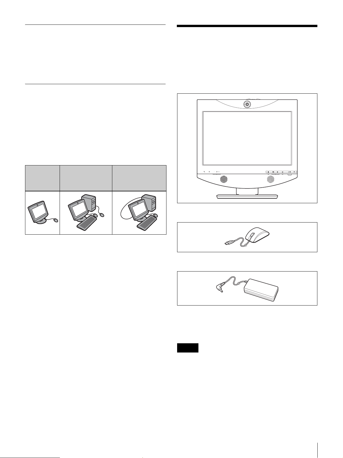
Intuitive Benutzeroberfläche
Die Benutzeroberfäche ermöglicht die unkomplizierte
Ausführung der Bedienvorgänge durch Klicken mit der
Maus (im Lieferumfang enthalten). Zudem ist das System
mit einer Onlinehilfe sowie Meldungen zur
Benutzerführung ausgestattet.
Verwenden als Computermonitor
Das PCS-TL30 kann sowohl als selbstständiges Gerät als
auch in Verbindung mit einem Computer betrieben
werden. In diesem Fall können Sie den Computer und das
PCS-TL30 mit jeweils einer eigenen Maus bedienen oder
eine Maus für beide Geräte verwenden.
Mit dem separat erhältlichen Datenlösungsmodul PCSADSM1 können Sie in einer Videokonferenz den Inhalt des
Computerbildschirms an den fernen Teilnehmer senden.
Überprüfen des
Packungsinhalts
Überprüfen Sie beim Auspacken des Geräts, dass alle im
Folgenden genannten Gegenstände vorhanden sind:
• PCS-TL30 Haupteinheit (1)
Verwendung
als
selbstständi
ges Gerät
Verwendung mit
einem Computer
und separaten
Zeigegeräten
Verwendung mit
einem Computer
und einem einzelnen
Zeigegerät
• Optische Maus PCS-RMU1 (1)
• Netzteil PCS-AC19V6A oder PCGA-AC19V7 (1)
• Netzkabel (1)
• Kurzanleitung (dieses Dokument) (1)
• CD-ROM (Betriebsanleitung) (1)
• Garantieheft (1)
Hinweis
Die beiliegende CD-ROM enthält die Betriebsanleitung
mit ausführlichen Informationen über die Bedienung und
alle Einstellungen des Gerätes. Dieses Dokument liegt in
Form einer PDF-Datei vor.
Überprüfen des Packungsinhalts
53
Page 54
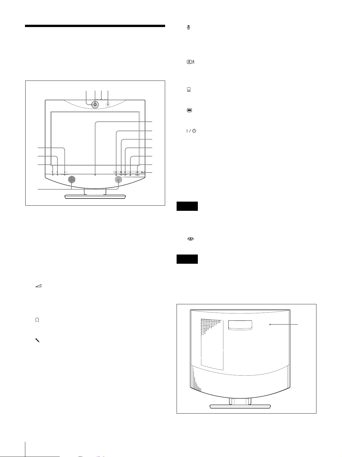
Namen und Funktionen
1 423
der Teile
Vorderseite
5
6
7
8
9
q;
qa
qs
qd
qf
qg
j Taste und LED (Mikro aus)
Ermöglicht die Stummschaltung des lokalen Systems.
Durch erneutes Drücken der Taste wird das Tonsignal
wieder an das ferne System gesendet.
k Taste und LED (Videokonferenz)
Zum Umschalten zwischen Computerbildschirm und
Videokonferenzbildschirm.
l Taste und LED (PC)
Zum Umschalten zum Computerbildschirm.
m Menütaste
Zum Aufrufen des Konfigurationsmenüs.
n Schalter und LED (Power)
Schaltet das System ein und aus.
Wenn das System im PC-Modus als Computerbildschirm
verwendet wird, wird es durch einmaliges Drücken dieses
Schalters ausgeschaltet.
Wenn das System im VK-Modus verwendet wird, wird es
durch einmaliges Drücken in den Bereitschaftsmodus
geschaltet. Zum Ausschalten im VK-Modus den Schalter
innerhalb von 5 Sekunden nach der ersten Betätigung
erneut drücken.
a Sende-Kontrolleuchte
Leuchtet, wenn lokale Videosignale an das ferne System
gesendet werden.
b Kameraobjektiv
c Hebel für Objektivabdeckung
d Mikrofon
e Lautstärketasten
Zum Einstellen der Lautstärke.
+: Erhöht die Lautstärke.
-: Senkt die Lautstärke.
f Kopfhörerbuchse (Stereo-Miniklinke)
Zum Anschluss von Kopfhörern (handelsüblich).
g Mikrofonbuchse (Miniklinke)
Zum Anschluss des optionalen Mikrofons PCS-A1 oder
PCSA-A3.
h Lautsprecher
Hinweis
Der Netzschalter ist während einer laufenden
Kommunikationssitzung gesperrt.
o LED „Memory Stick“
Zeigt den Status des Memory Stick-Steckplatzes.
Hinweis
Entnehmen Sie den „Memory Stick“ nicht, solange die
LED leuchtet.
Rückseite
1
i Online-Leuchte
Zeigt hauptsächlich den Status ankommender und
abgehender Gespräche an.
54
Namen und Funktionen der Teile
Page 55
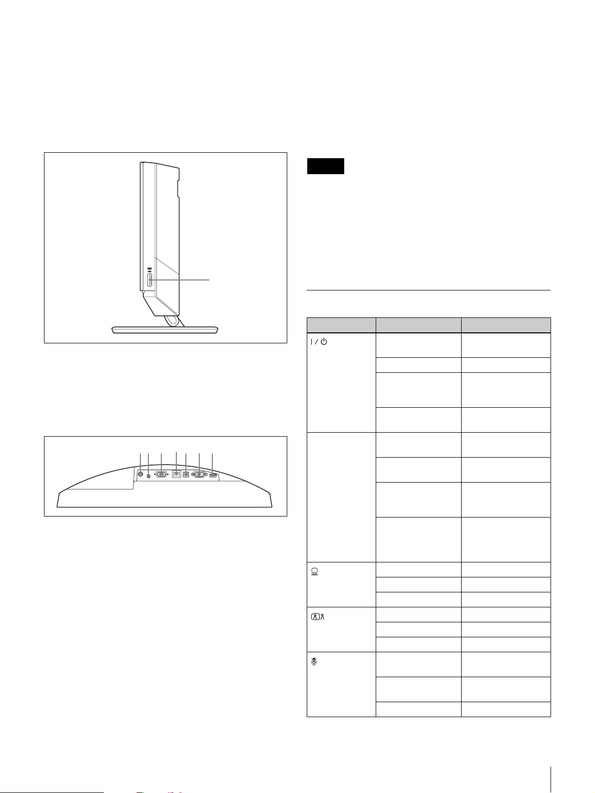
a Rückwand
7653421
Diese Abdeckung entfernen, um Zugang zur
Anschlussleiste zu erhalten. Hinter der Rückwand befindet
sich außerdem der Anschlussbereich zwischen dem Fuß
und dem Monitor. Die Höhe des Monitors lässt sich durch
Ändern der Schraubenpositionen einstellen.
Rechte Seite
1
a Memory Stick-Steckplatz
Zum Einstecken eines „Memory Stick“.
Anschlussleiste
(hinter der Rückwand, von unten)
a Netzteilanschluss (19,5 V Gleichstrom)
Zum Anschließen des im Lieferumfang enthaltenen
Netzteils PCS-AC19V6A oder PCGA-AC19V7.
b AUDIO IN: Eingangsbuchse für PC-Sound
(Stereo-Miniklinke)
Diese Buchse an den Audioausgang eines mit dem RGB
IN-Anschluss verbundenen Computers anschließen.
c RGB IN-Anschluss (15-poliger D-Sub-
Minianschluss)
Zum Anschließen an den RGB-Ausgang eines Computers.
d 100BASE-TX/10BASE-T-Anschluss (RJ-45)
Diesen Anschluss mit einem LAN-Kabel der Kategorie 5
mit einem Hub oder ähnlichen Gerät verbinden.
Der Anschluss ist mit einer Link/Data-LED (grün) und
einer 100/10-Mb/s-LED (orange) ausgestattet.
e PC-Anschluss
Dieser Anschluss wird verwendet, wenn der PCS-TL30
und ein mit dem RGB IN-Anschluss verbundener
Computer mit derselben Maus bedient werden. Verbinden
Sie den Anschluss mit einem USB-Anschluss des
Computers.
Hinweis
Das verwendete USB-Kabel darf nicht länger als 3 m sein.
f RS-232C-Anschluss (9-poliger D-Sub-Anschluss)
Dieser Anschluss wird nur für die Wartung des Systems
verwendet.
g Mausanschluss
Zum Anschließen der beiliegenden Maus PCS-RMU1.
Namen und Funktionen der LEDs
LED Status Bedeutung
(Power) *
Online * Blinkt blau (3 Mal
(PC) *
(Videokonferenz)
(Mikro aus) *
Leuchtet grün Gerät ist
eingeschaltet
Leuchtet orange Bereitschaft
Blinkt orange
(einmal pro
Sekunde)
Aus Gerät ist
pro Sekunde)
Leuchtet blau Kommunikation
Blaues
unterbrochenes
Blinken
Aus Offline (keine
Leuchtet blau Computermonitor
Leuchtet weiß
Aus Bereitschaft
Leuchtet blau
*
Leuchtet weiß
Aus Bereitschaft
Leuchtet orange Mikrofon
Leuchtet weiß Mikrofon
Aus Bereitschaft
Lüfterstörung
ausgeschaltet
Senden/Empfangen
von Signalen
findet statt
Gespräch verpasst
verpassten
Gespräche) oder
Bereitschaft
Videokonferenzmonitor
Videokonferenzmonitor
Computermonitor
ausgeschaltet
eingeschaltet
Namen und Funktionen der Teile
55
Page 56
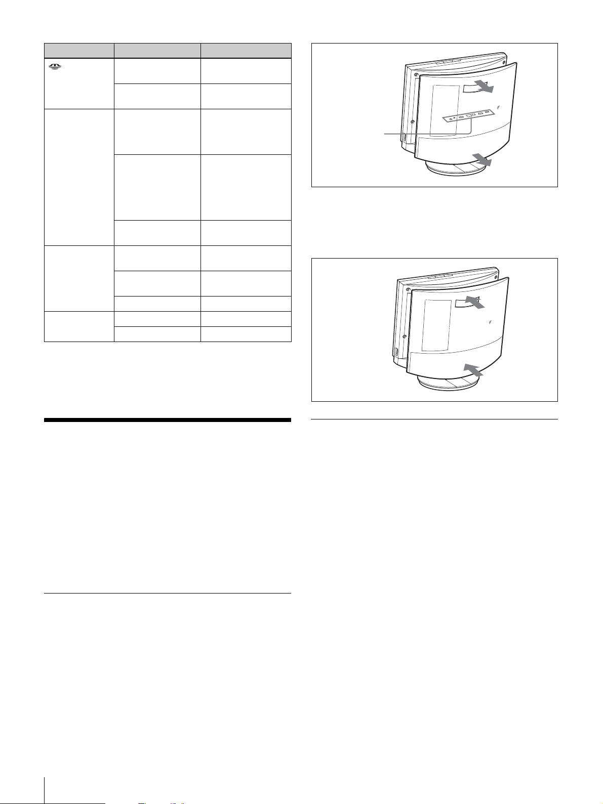
LED Status Bedeutung
(„Memory
Stick“)
SendeKontrolleuchte
Link/Data Leuchtet grün Verbindung
100/10 Mbit/s Leuchtet orange 100 Mbit/s
Leuchtet orange
Aus Kein Zugriff auf
Leuchtet orange Kamerabild wird an
Blinkt orange
(5-Mal pro
Sekunde)
Aus Kamerabild wird
Blinkt grün Daten werden
Aus Verbindung ist offline
Aus 10 Mbit/s
Zugriff auf „Memory
Stick“
„Memory Stick“
fernen Teilnehmer
gesendet
(Objektivabdeckung)
„
Closed“
Bild
(Geschlossen) wird
an fernen
Teilnehmer gesendet
(Objektivabdeckung
geschlossen)
nicht gesendet
hergestellt
übertragen
Anschlussleiste
(unter der
Rückwand)
Anbringen der Rückwand
Drücken Sie die Rückwand gegen das Gerät. Achten Sie
dabei auf die richtige Ausrichtung der vier Stifte.
* Die LED leuchtet während des Systemstarts. Wenn ein unzulässiger
Temperaturwert erkannt wird, blinkt die LED, und das Gerät wird
abgeschaltet.
Systemanschlüsse
Dieser Abschnitt zeigt einige repräsentative
Anschlussmöglichkeiten für das System.
Das PCS-TL30 kann sowohl als selbstständiges Gerät
betrieben als auch als Monitor an einen Computer
angeschlossen werden In diesem Fall können Sie den
Computer und das PCS-TL30 mit jeweils einer eigenen
Maus bedienen oder den Computer und das PCS-TL30 mit
einem USB-Kabel verbinden und eine Maus für beide
Geräte verwenden.
Hinweis zu den Anschlüssen
Die Anschlüsse des Systems befinden sich unter der
Rückwand. Entfernen Sie zum Herstellen der
Verbindungen die Rückwand, und bringen Sie sie danach
wieder an.
Sicherheitshinweise für die
Verbindungen
Warnung
• Verwenden Sie nur das im Lieferumfang enthaltene
Netzteil und Netzkabel.
• Stecken Sie den Netzstecker und den Adapterstecker des
Netzteils stets vollständig in die Steckdose bzw. Buchse.
• Schließen Sie den 100BASE-TX/10BASE-T-Anschluss
nicht an Netzwerke an, in denen übermäßige
Spannungen auftreten können.
Sicherheitshinweis
• Schalten Sie vor dem Herstellen der Verbindungen alle
Komponenten aus.
• Um Beschädigungen des Geräts zu verhindern, dürfen
Stecker nur bei ausgeschaltetem Gerät eingesteckt oder
gezogen werden.
Entfernen der Rückwand
Ziehen Sie die Rückwand zu sich heran.
56
Systemanschlüsse
Page 57
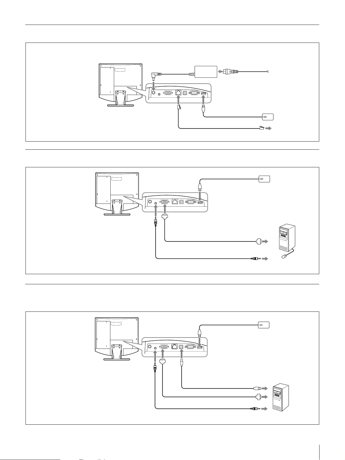
Anschlussbeispiel (Verwendung als selbstständiges Gerät)
Stellen Sie die Verbindungen in der
Reihenfolge 1 - 5 her.
Videokommunikations
system PCS-TL30
3 Zum
Netzteilanschluss
(19,5 V Gleichstrom)
10BASE-T-Anschluss
Netzteil PCS-AC19V6A
oder PCGA-AC19V7
(beiliegend)
1 Zum
MausanschlussZum 100BASE-TX/ 2
UTP-Kabel Kategorie 5 (unverdrillt, handelsüblich)
4 Netzkabel (beiliegend)
5 Zur Steckdose
(120 V ~)
Optische Maus PCSRMU1 (beiliegend)
Zum LAN
Anschlussbeispiel für die Verwendung mit einem Computer (separate Maus)
Optische Maus PCS-
Videokommunikations
system PCS-TL30
Zur AUDIO IN-Buchse
Zum Mausanschluss
Zum Anschluss RGB IN
Kabel mit 15-poligem
D-Sub-Minianschluss
(handelsüblich)
Zum RGB-Ausgang
RMU1 (beiliegend)
Computer
Audiokabel mit StereoMiniklinkenstecker (handelsüblich)
Zum Audioausgang
Anschlussbeispiel für die Verwendung mit einem Computer (gemeinsam
genutzte Maus)
Optische Maus PCS-
Videokommunikations
system PCS-TL30
* Das verwendete USB-Kabel
darf nicht länger als 3 m sein.
Zur AUDIO
IN-Buchse
Zum Mausanschluss
Zum
Anschluss
RGB IN
Kabel mit 15-poligem D-SubMinianschluss (handelsüblich)
Miniklinkenstecker (handelsüblich)
Zum PC-Anschluss
USB-Kabel
(handelsüblich) *
Zum USB-Anschluss
Zum RGB-Ausgang
Zum AudioausgangAudiokabel mit Stereo-
RMU1 (beiliegend)
Computer
Systemanschlüsse
57
Page 58
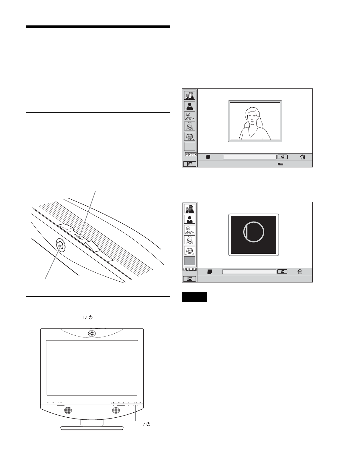
Ein- und Ausschalten des
Systems
Die Anzeige des Schalters leuchtet orange. Das
Videokommunikationssystem ist jetzt eingeschaltet. Wenn
der Start des Systems abgeschlossen ist, leuchtet die LED
grün. The Menü „Start“ und das Bild der lokalen Kamera
werden auf dem Monitor angezeigt.
Vor dem Einschalten müssen alle Verbindungen des
Systems ordnungsgemäß hergestellt sein.
Je nach der verwendeten Software können die angezeigten
Bildschirme von den hier abgebildeten abweichen.
Öffnen der Objektivabdeckung
Das System ist mit einer Objektivabdeckung zum
Abdecken der Kamera ausgestattet. Öffnen Sie vor Beginn
einer Videokonferenz die Objektivabdeckung, indem Sie
den Objektivabdeckungsschalter auf der Oberseite des
Systems nach rechts schieben. Wenn die
Objektivabdeckung geschlossen ist, kann der
Fernteilnehmer das Bild am lokalen Standort nicht sehen.
Objektivabdeckungsschalter
Menü „Start“
EMPTY
Zum Aktivieren der Funkton auf das Symbol klicken.
Wenn die Objektivabdeckung geschlossen ist, wird das
Menü „Start“ wie in der folgenden Abbildung angezeigt:
CLOSED
Number :012.345.678.912
Kamera
Einschalten des Systems
Drücken Sie die Taste (Power) am PCS-TL30.
Closed
EMPTY
Zum Aktivieren der Funkton auf das Symbol klicken.
Hinweise
Number :012.345.678.912
• Bei der ersten Betätigung des Netzschalters nach dem
Anschließen des Netzkabels an eine Netzsteckdose kann
es unter Umständen 10 Sekunden dauern, bis die LED
leuchtet.
• Wenn Sie das Videokommunikationssystem zum ersten
Mal nach der Installation einschalten, wird der SetupAssistent angezeigt. Konfigurieren Sie das System mit
Hilfe des Konfigurationsassistenten.
58
Ein- und Ausschalten des Systems
Taste (Power)
Page 59
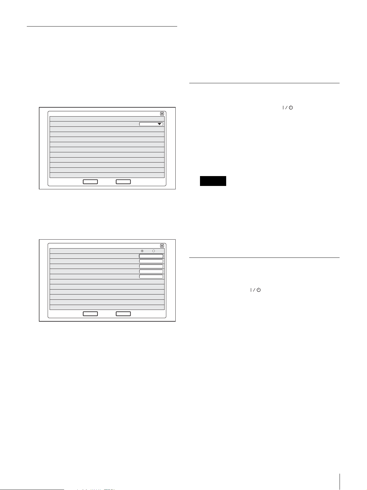
Setup-Assistent für die
Ersteinrichtung
Wenn Ihnen die erforderlichen Einstellungen nicht
bekannt sind, wenden Sie sich an den
Netzwerkadministrator.
Je nach der verwendeten Monitorsoftware können einige
Einstellungen von den hier angegebenen Bezeichnungen
abweichen.
1
Wählen Sie im Menü „Language“ die Sprache aus, die
für Menüs und Meldungen verwendet werden soll.
1/2
Language
Next
2
Klicken Sie auf „Next“.
3
Nehmen Sie die erforderlichen Einstellungen für das
Cancel
English
LAN vor.
DHCP-Modus
Host Name
IP-Adresse
Netzwerkmaske
Gateway-Adresse
DNS-Adresse
Auto
2/2
Aus
4
Klicken Sie auf „Speichern“.
Die Einstellungen werden gespeichert.
Ausschalten des Systems
1
Drücken Sie zweimal die Taste (Power).
Nach einmaligem Drücken des Schalters erscheint die
Meldung „Bereitschaftsmodus wird vorbereitet. Zum
Ausschalten noch einmal den Netzschalter drücken.“
angezeigt. Drücken Sie den Netzschalter erneut.
2
Schalten Sie die anderen Geräte aus, die für die
Videokonferenz verwendet werden.
Hinweise
• Schalten Sie das System aus, wenn es längere Zeit
nicht verwendet wird. Solange das Gerät
ausgeschaltet ist, können keine Anrufe von
Fernteilnehmern empfangen werden.
• Wenn das System im PC-Modus als
Computermonitor verwendet wird, wird es durch
einen Druck auf den Netzschalter ausgeschaltet.
• In einer Konferenz ist der Netzschalter funktionslos.
Aktivieren des Bereitschaftsmodus
des Videokommunikationssystems
Speichern
Zurück
DHCP-Modus: Für die DHCP-Einstellungen
(Dynamic Host Configuration Protocol).
Auto: Weist automatisch Ihre IP-Adresse, die
Teilnetzmaske, die Gateway-Adresse und die
DNS-Adresse zu.
Aus: Deaktiviert DHCP. In diesem Fall
konfigurieren Sie Ihre IP-Adresse, die
Teilnetzmaske, die Gateway-Adresse und die
DNS-Adresse manuell.
Host Name: Geben Sie den Hostnamen ein.
IP-Adresse: Geben Sie Ihre IP-Adresse ein.
Netzwerkmaske: Geben Sie Ihre Teilnetzmaske ein.
Gateway-Adresse: Geben Sie die Standard-
Gateway-Adresse ein.
DNS-Adresse: Geben Sie die Adresse für den DNS-
Server (Domain Name System-Server) ein.
Wenn Sie den Schalter (Power) des PCS-TL30
drücken, erscheint die Meldung „Bereitschaftsmodus wird
vorbereitet. Zum Ausschalten noch einmal den
Netzschalter drücken.“. Das System wechselt nach einigen
Sekunden in den Standby-Modus.
Im Standby-Modus können Anrufe von Fernteilnehmern
empfangen werden.
Um aus dem Standby-Modus in den normalen Modus zu
wechseln, drücken Sie einmal den Netzschalter.
Ein- und Ausschalten des Systems
59
Page 60
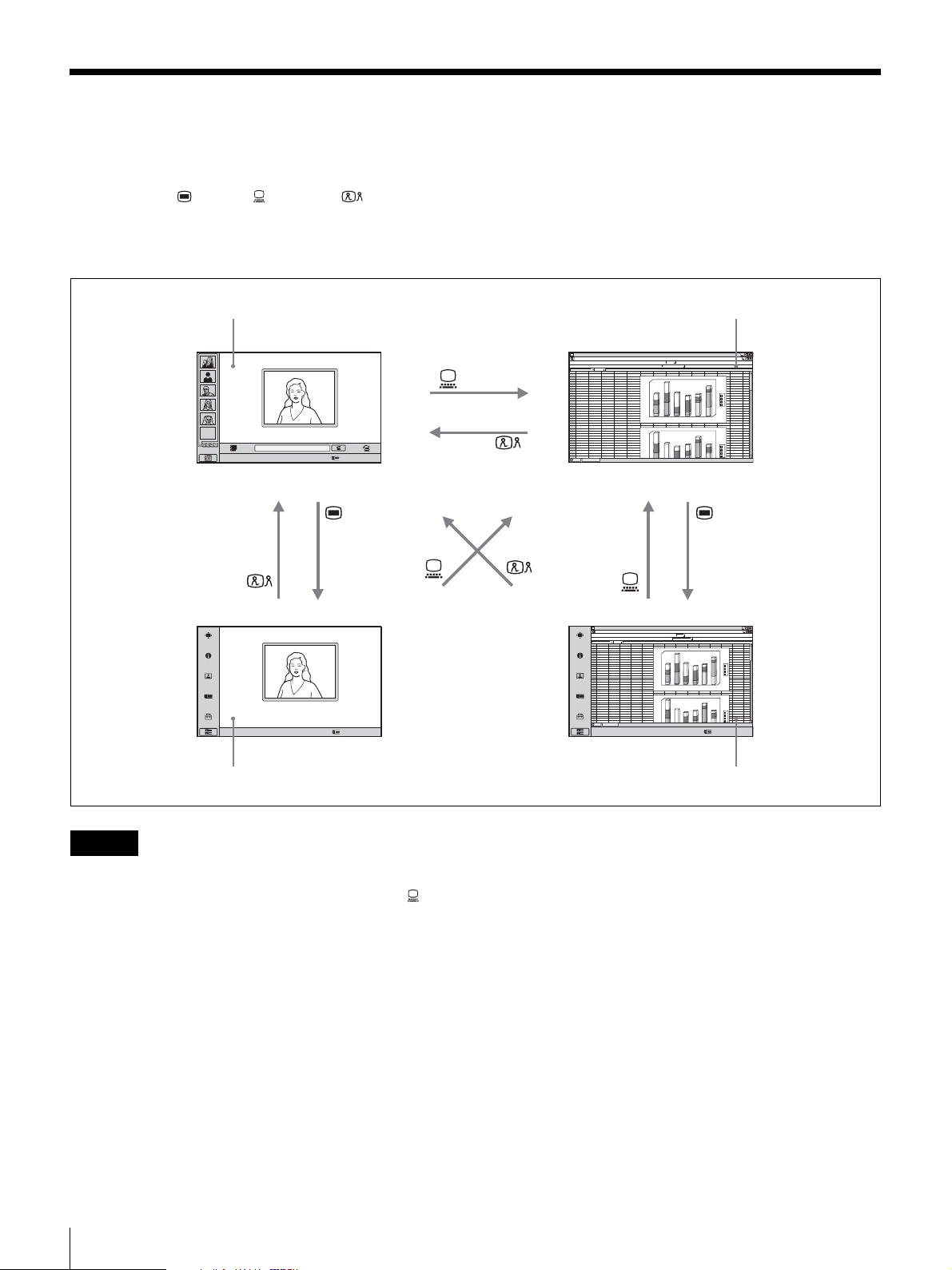
Umschalten zwischen Videokonferenzmonitor und
Computermonitor
Mit den Tasten (Menü) (PC) und
(Videokonferenz) unten rechts am Gerät können Sie
zwischen Videokonferenzbildschirm und
Computerbildschirm umschalten.
Videokonferenzbildschirm (Menü „Start“) Normaler Computerbildschirm
Videokonferenzbildschirm (Menü „Start“)
ABCDEFGH IJ KLMN
1
abcd
2
EMPTY
Zum Aktivieren der Funkton auf das Symbol klicken.
Number :012.345.678.912
3
4
5
6
7
8
9
10
11
12
13
14
15
16
17
18
19
20
21
22
23
24
25
26
27
28
29
30
31
32
33
34
46
23
12
67
45
4
12
26
5
16
57
6
7
23
69
15
44
76
abcd
45
67
4
26
12
5
57
16
6
23
45
12
15
78
46
23
7
69
34
180
56
76
1
6
0
38
1
4
0
13
12
1
2
0
1
0
0
6
0
5
0
4
0
2
0
0
1
2
180
1
6
0
56
1
4
0
76
23
1
2
0
34
1
0
0
12
13
0
6
5
0
4
0
d
c
b
a
6
5
4
3
d
c
b
a
Zum Aktivieren der Funkton auf das Symbol klicken.
Videokonferenzbildschirm (Menü Computerbildschirm (Menü „Konfiguration“)
Videokonferenzbildschirm (Menü „Konfiguration“)
Number :012.345.678.912
Hinweise
• Wenn das PCS-TL30 nicht an einen Computer
angeschlossen ist, wird beim Drücken der Taste (PC)
zum Umschalten auf den Computermonitor die Maus
deaktiviert.
• Wenn während einer Kommunikation ein Sub-Bild
angezeigt wird, bleibt dieses auch beim Umschalten auf
den Computermonitor erhalten. Das im Sub-Bild
angezeigte Video kann vom fernen oder vom lokalen
System stammen.
• Wenn für den PCS-TL30 und den Computer separate
Mäuse verwendet werden, ist die aktive Maus vom
aktuellen Monitorbildschirm abhängig: Wenn der
normale Computerbildschirm angezeigt wird, ist die an
den Computer angeschlossene Maus aktiv. Wenn andere
Bildschirme angezeigt werden, ist die an den PCS-TL30
angeschlossene Maus aktiv.
ABCDEFGH IJ KLMN
1
2
abcd
3
12
46
23
34
4
4
5
5
6
6
7
69
8
44
9
10
11
12
13
14
15
16
17
18
19
20
21
22
23
24
25
abcd
26
4
27
5
28
6
29
12
30
46
31
69
32
33
34
Zum Aktivieren der Funkton auf das Symbol klicken.
180
67
45
56
12
26
76
1
6
0
16
57
38
4
0
1
7
23
13
76
15
12
2
0
1
0
1
0
6
0
5
0
0
4
0
2
0
1
2
180
6
0
1
67
45
56
4
0
1
12
26
76
16
57
23
2
0
1
45
23
34
0
0
1
78
15
12
7
23
13
6
0
5
0
4
0
3
5
4
d
c
b
a
6
d
c
b
a
Number :012.345.678.912
60
Umschalten zwischen Videokonferenzmonitor und Computermonitor
Page 61
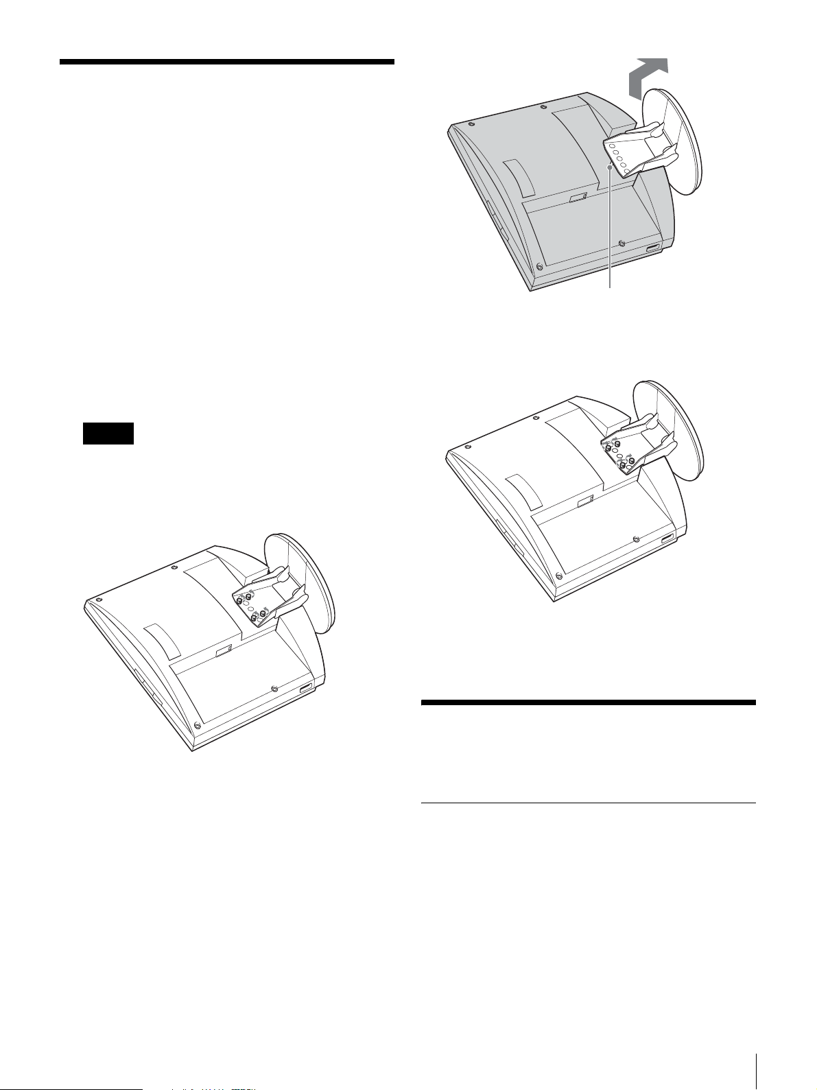
Höheneinstellung des
Monitors
Der Fuß und der Monitor des PCS-TL30 sind mit
Halteschrauben verbunden. Im Monitor befinden sich im
Abstand von 25 mm drei Reihen von Schraubenlöchern.
Im Lieferzustand ist der Monitor in der niedrigsten
Position fixiert. Wählen Sie eine andere Reihe von
Löchern, um die Höhe des Monitors zu ändern.
1
Nehmen Sie die Rückwand des Geräts ab.
Eine Anleitung hierzu finden Sie Seite 56.
2
Lösen Sie mit einer Münze o. ä. die 4 Schrauben,
heben Sie den Fuß an, und führen Sie den
Positionierungsstift in die Öffnung für die neue
Position des Fußes.
Hinweis
Ehe Sie die Höhe des Monitors entsprechend der
obigen Beschreibung ändern, muss das Gerät
ausgeschaltet werden. Legen Sie den Monitor mit der
Frontseite nach unten auf ein weiches Tuch o. ä.
Positionierungsstift
3
Ziehen Sie die 4 Schrauben zur Sicherung des Fußes
mit einer Münze o. ä. fest.
4
Bringen Sie die Rückwand wieder an.
Hinweise für die optimale
Nutzung des Gerätes
Betriebs- und Lagerbedingungen
Folgende Bedingungen sind für den Betrieb oder die
Lagerung des Systems nicht geeignet:
• Extreme Hitze oder Kälte
• Feuchtigkeit und Staub
• Starke Erschütterungen
• Nähe zu starken Magnetquellen
• Nähe zu starken elektromagnetischen
Strahlungsquellen, wie Radio- oder
Fernsehsendemasten
• Hohe Interferenzen
Höheneinstellung des Monitors / Hinweise für die optimale Nutzung des Gerätes
61
Page 62

LCD-Bildschirm
• Der LCD-Bildschirm darf keiner direkten
Sonneneinstrahlung ausgesetzt werden, da dies zu einer
Beschädigung der Bildschirmoberfläche führen kann.
• Der LCD-Bildschirm darf nicht eingedrückt, zerkratzt
oder als Unterlage für Gegenstände verwendet werden,
da hierdurch die Bilddarstellung verzerrt oder die LCDAnzeige beschädigt werden kann.
• Wenn das System unter kalten Bedingungen verwendet
wird, können Schmier- oder Verdunklungseffekte in der
Bildanzeige auftreten. Dies sind keine Zeichen für
Gerätefehler. Diese Erscheinungen verschwinden bei
höherer Außentemperatur wieder.
• Wenn Bilder für längere Zeit angezeigt werden, kann die
Bilddarstellung unscharf werden. Dieses Phänomen
verschwindet nach einer Weile wieder.
• Es wird dadurch verursacht, dass sich Bildschirm und
Gehäuse während des Systembetriebs erwärmen und
stellt keine Funktionsstörung dar.
LCD-Anzeige
Obgleich die LCD-Anzeige unter Einsatz von
Hochpräzisionstechnologien gefertigt wurde, können
konstante schwarze oder helle (rote, blaue oder grüne)
Lichtpunkte auf dem LSD-Bildschirm erscheinen.
Außerdem kann der Bildschirm bei der Betrachtung aus
einem bestimmten Winkel streifig und mit unregelmäßiger
Helligkeit erscheinen. Dies ist eine spezifische
Eigenschaft von LCD-Bildschirmen und keine
Fehlfunktion.
Integrierte Lautsprecher
Lautsprecher erzeugen Magnetfelder. Um
Beschädigungen der Daten zu vermeiden, dürfen
Magnetbänder und Datenträger nicht in der Nähe von
Lautsprechern aufbewahrt werden.
Reinigen des Gerätes
• Ziehen Sie vor dem Reinigen des PCS-TL30 das
Netzkabel aus der Steckdose.
• Die Oberfläche des LCD-Bildschirms ist mit einer
Spezialbeschichtung behandelt. Wischen Sie die
Bildschirmoberfläche zum Entstauben vorsichtig mit
einem trockenen, weichen Tuch ab.
• Verwenden Sie keine Lösungsmittel wie Alkohol,
Benzin oder Verdünnung, da diese zur Beschädigung
oder Verfärbung der Oberflächenbeschichtung führen
können.
• Bei der Verwendung chemischer Reinigungstücher sind
die Sicherheitshinweise zu beachten.
• Lassen Sie keine flüchtigen Substanzen wie
Insektenvernichtungsmittel in Kontakt mit dem Gerät
kommen, und vermeiden Sie längere Berührungen durch
Gegenstände aus Gummi oder Kunststoff, da dies zu
Beschädigungen oder Verfärbungen der Oberfläche
führen kann.
Technische Daten
PCS-TL30 Videokommunikationssystem
Dieses Gerät entspricht den ITU-T-Empfehlungen H.320
und IETF SIP.
Bewegtes Bild
Betriebsbandbreite
64 kb/s bis 2048 kb/s
Codierung H.261/H.263/H.263+/H.263++/H.264
(ITU-T Empfehlung)
MPEG4 Simple Profile
Bildelemente CIF: 352 Pixel × 288 Zeilen
QCIF: 176 Pixel × 144 Zeilen
Standbild
Pixel 704 Pixel × 576 Zeilen
Codierung H.261 (ITU-T Recommendation) Annex.
D (4CIF)
H.263 (Sonderformat dieses Systems)
Ton
Bandbreite 14 kHz (MPEG4 Audio)
7 kHz (G.722 entspricht der ITU-T-
Empfehlung)
3,4 kHz (G.711/G.728/G.729 entspricht
der ITU-T Empfehlung)
Übertragungsrate
64 kb/s, 96 kb/s (MPEG4 Audio)
56 kb/s, 64 kb/s (G.711 entspricht der
ITU-T-Empfehlung)
48 kb/s, 56 kb/s, 64 kb/s (G.722
entspricht der ITU-T-Empfehlung)
16 kb/s (G.728 entspricht der ITU-T-
Empfehlung)
8 kb/s (G.729 entspricht der ITU-T-
Empfehlung)
Netzwerk
Multiplexfunktion
Video, Audio, Daten
Frameformat H.225.0 (entspricht der ITU-T-
Empfehlung)
Schnittstelle LAN (100BASE-TX/10BASE-T)
Unterstützte LAN-Protokolle
HTTP
FTP
62
Technische Daten
Page 63

Telnet
RTP/RTCP
TCP/UDP
IP
Fernsteuerung
Steuerung der Kamera am fernen Standort
H.281 (entspricht der ITU-T-
Empfehlung)
Kamera
Bildwandler 1/3,2 Zoll Farbe CMOS (insgesamt
effektive Pixel: ca. 1,3 Millionen)
Objektiv f = 2,3 mm
F = 1:2,8
Horizontalwinkel: ca. 88°
Vertikalwinkel: ca. 73°
Brennweite 300 mm
Schwenken/Neigen/Zoomen
Digital
Integrierter automatischer Weißabgleich
Bildfrequenz 30/15 fps, automatisch an
Umgebungsbeleuchtung angepasst
Monitor
Größe 17,1-Zoll-Bereich, Breitwand
Auflösung 1280 × 768 (WXGA)
Reaktionszeit maximal 13 ms
Kontrastrate 600 : 1
Blickwinkel mindestens 176 Grad
Anzahl der Farben
16.700.000 Farben
Anzeige-Controller
PinP 4 Ecken
PandP drei Fenster
Eingang intern: Videokommunikation
Externes RGB-Signal: Computermonitor
Brennweite Normal, Zoom, Weit
RGB-Modus 640 × 480, 800 × 600, 1024 × 768,
1280 × 768 usw.
Zoomanzeige ist möglich.
Lautsprecher
Lautsprecher 3 W × 2
Mikrofon
Frequenzbereich
14 kHz
Direktionale Eigenschaften
Richtmikrofon
Allgemein
Betriebsspannung
19,5 V
Stromverbrauch
6,15 A
Betriebstemperatur
5 °C bis 35 °C
Betriebsluftfeuchtigkeit
20 % bis 80 %
Lagertemperatur
–20 °C bis +60 °C
Luftfeuchtigkeit für Lagerung
20 % bis 80 % (nicht kondensierend)
Abmessungen 424 × 376 × 95,5 mm (B×H×T)
3
(16
/4 × 14 7/8 × 3 7/8 Zoll) (ohne
Fuß)
424 × 419 × 258 mm (B×H×T)
3
(16
/4 × 16 1/2 × 10 1/4 Zoll) (mit Fuß)
Masse ca. 8 kg
Mitgeliefertes Zubehör
Optische Maus PCS-RMU1 (1)
Netzteil PCS-AC19V6A/PCGA-
AC19V7 (1)
Netzkabel (1)
CD-ROM (1)
Kurzanleitung (1)
Garantieheft (1)
PCS-AC19V6A oder PCGA-AC19V7 Netzteil
Betriebsspannung
100 bis 240 V ~; 50/60 Hz; 1,8 A
Ausgang 19,5 V; 6,15 A
Betriebstemperatur
5 °C bis 35 °C
Betriebsluftfeuchtigkeit
20 % bis 80 %
Lagertemperatur
–20 °C bis +60 °C
Luftfeuchtigkeit für Lagerung
20 % bis 80 % (nicht kondensierend)
Abmessungen 80 × 40 × 160 mm (B×H×T) (3
5
1
/8 × 6 3/8 Zoll)
1
/4 ×
Masse ca. 800 g
Mikrofon PCS-A1 (optional)
Bandbreite 13 kHz
Direktionale Eigenschaften
Kugelcharakteristik
Abmessungen 74 × 16 × 93 mm (B×H×T)
21
(3 ×
/32 × 3 3/4 Zoll)
Gewicht ca. 170 g
Stromversorgung
Über Anschlusskabel
PCSA-A3 Mikrofon (optional)
Bandbreite 13 kHz
Direktionale Eigenschaften
Unidirektional
Dimension 68 × 16 × 96 mm (B×H×T)
Gewicht ca. 200 g
Stromversorgung
3
(2
/4 × 21/32 × 3 7/8 Zoll)
Über Anschlusskabel
Technische Daten
63
Page 64
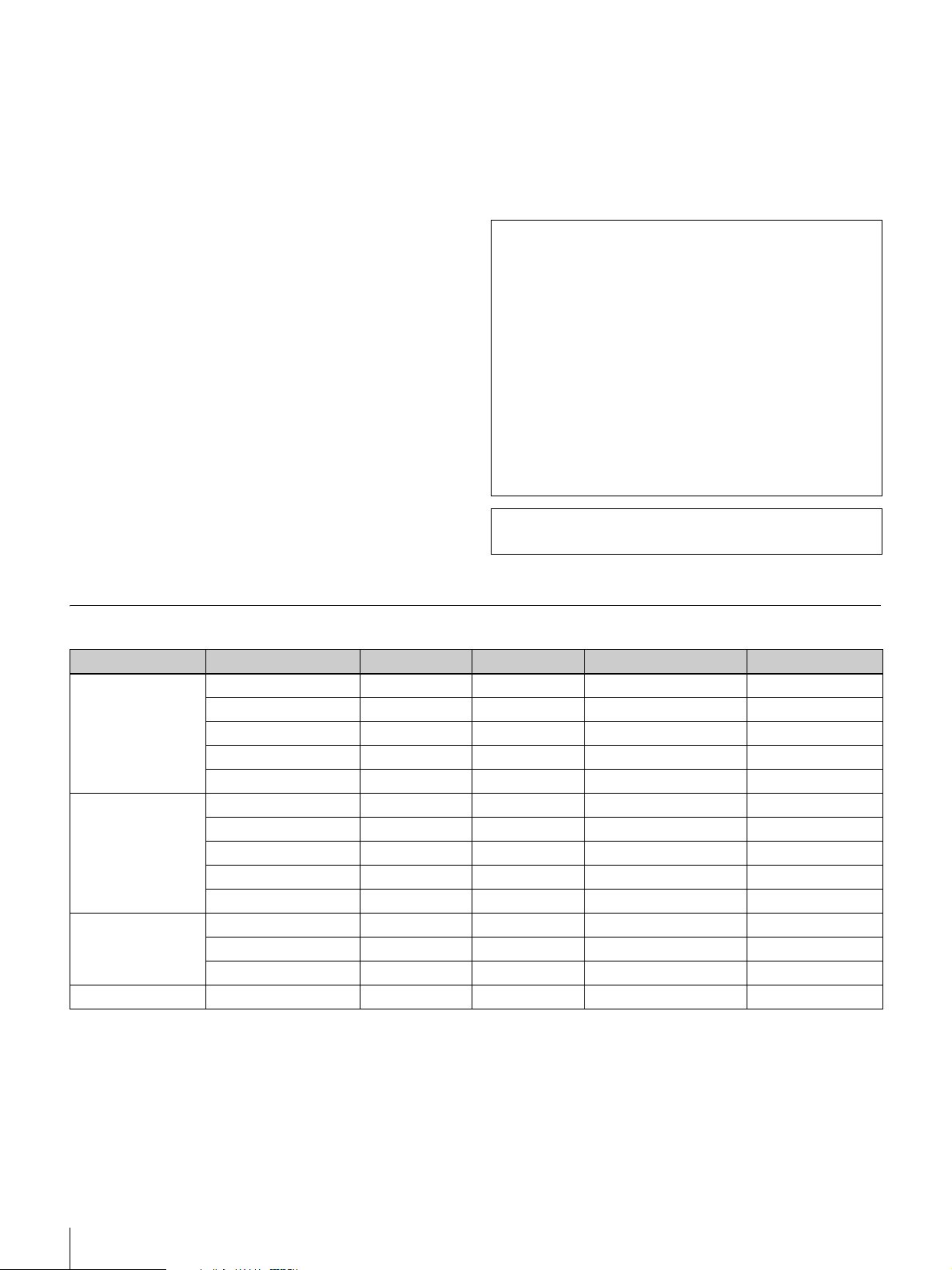
Datenlösungsmodul PCSA-DSM1
(optional)
Stromverbrauch
20 W max.
Betriebstemperatur
5 °C bis 35 °C
Betriebsluftfeuchtigkeit
20 % bis 80 %
Lagertemperatur
–20 °C bis +60 °C
Luftfeuchtigkeit für Lagerung
20 % bis 80 % (nicht kondensierend)
Abmessungen 107 × 250 × 34 mm (B×H×T)
Masse ca. 550 g
Mitgeliefertes Zubehör
1
(4
/4 × 9 7/8 × 1 3/8 Zoll) (ohne
herausragende Teile)
Kurzanleitung (1)
Garantieheft (1)
Software PCSA-SP1 SIP (optional)
Mitgeliefertes Zubehör
Aufkleber mit Seriennummer (1)
Betriebsanleitung (1)
Design und Spezifikationen können ohne Vorankündigung
geändert werden.
Die Echokompensation des Geräts wurde unter Lizenz
der Nippon Telegraph and Telephone Corporation
entwickelt. Die Nippon Telegraph and Telephone
Corporation ist darüber hinaus Inhaber des Copyrights
der Echokompensations-Software.
Die im Gerät verwendeten Technologien dürfen weder
ganz noch teilweise als Waffen oder zur Herstellung von
Waffen verwendet oder verkauft werden. Alle Rechte an
der Software des Gerätes und den Kopien der
Dokumentation gehören der Nippon Telegraph and
Telephone Corporation und Sony. Es ist nicht erlaubt, die
im Gerät verwendeten Technologien zu kopieren, einem
sog. Reverse Engineering zu unterziehen, zu
dekompilieren, zu zerlegen oder zu modifizieren.
Dieses Produkt verwendet von Ricoh Co., Ltd.
produzierte und gefertigte Ricoh-Bitmapschriftarten.
RGB-Eingangs- und Ausgangsspezifikationen
Bildelement Signalformat fH (kHz) fV (Hz) Grafikkarte (MHz) Sync
640 × 480 VGA-Modus 31,469 59,94 25,17 H-neg, V-neg
Macintosh 13" 35 66,667 30,24 H-neg, V-neg
VGA VESA 72 Hz 37,861 72,809 31,5 H-neg, V-neg
VGA VESA 75 Hz 37,5 75 31,5 H-neg, V-neg
VGA VESA 85 Hz 43,269 85,008 36 H-neg, V-neg
800 × 600 SVGA VESA 56 Hz 35,156 56,25 36 H-pos, V-pos
SVGA VESA 60 Hz 37,879 60,317 40 H-pos, V-pos
SVGA VESA 72 Hz 48,077 72,188 50 H-pos, V-pos
SVGA VESA 75 Hz 46,875 75 49,5 H-pos, V-pos
SVGA VESA 85 Hz 53,674 85,061 56,25 H-pos, V-pos
1024 × 768 XGA VESA 60 Hz 48,363 60,004 65 H-neg, V-neg
XGA VESA 70 Hz 56,476 70,069 75 H-neg, V-neg
XGA VESA 75 Hz 60,023 75,029 78,75 H-pos, V-pos
1280 × 768 WXGA VESA 60 Hz* 47,693 59,992 80,12 H-neg, V-pos
* Kann nicht über das Datenlösungsmodul PCSA-DSM1 übertragen werden.
64
Technische Daten
Page 65

Español
ADVERTENCIA
Para reducir el riesgo de que se produzcan
incendios o descargas eléctricas, no
exponga el producto a la lluvia o a la
humedad.
Para evitar descargas eléctricas, no abra la
unidad. En caso de avería, solicite el
servicio de personal cualificado
únicamente.
ADVERTENCIA
Utilice el adaptador de ca suministrado con el equipo como
fuente de suministro de alimentación.
La unidad se suministra con uno de los adaptadores de
alimentación de ca que figuran en la lista facilitada a
continuación.
Fabricación Número de modelo
Sony PCS-AC19V6A
Sony PCGA-AC19V7
ES
La utilización de cualquier otra fuente de alimentación
podría provocar un incendio.
Desconecte el enchufe del cable del adaptador de ca para
apagar el dispositivo.
El enchufe del cable de alimentación de este equipo debe
utilizarse para desconectar la red eléctrica.
Asegúrese de que la toma de corriente está instalada cerca
del equipo y se puede acceder a ella con facilidad.
En el caso de que se produjera un funcionamiento anormal,
desconecte el enchufe de la corriente.
AVISO
Utilice el cable de alimentación aprobado por el organismo
de homologación competente en aquellos países donde se
vaya a utilizar la unidad.
PRECAUCIÓN sobre el puerto LAN
Por razones de seguridad, no conecte el puerto LAN a
ningún dispositivo de red que pudiese tener una tensión
demasiado elevada.
Para los clientes de Europa
Advertencia
Éste es un producto de classe A. En un ambiente
doméstico, este producto puede causar interferencias
radioeléctricas, en cuyo caso el usuario puede tener que
tomar las medidas adecuadas.
En el caso de producirse interferencias, póngase en
contacto con el centro de servicio técnico Sony autorizado
más cercano.
65
Page 66

Tabla de contenido
Documentos suministrados.....................67
Características...........................................67
Sistema de comunicaciones de vídeo portátil
integrado............................................ 67
Interfaz de usuario intuitiva........................ 68
Utilización como pantalla de ordenador..... 68
Comprobación del contenido del
paquete................................................68
Nombres y funciones de las piezas.........69
Nombres y funciones de los indicadores .... 70
Conexiones del sistema ...........................71
Acerca de los conectores ............................ 71
Precauciones durante la conexión............... 71
Ejemplo de conexión (utilización en modo
autónomo) ......................................... 72
Ejemplo de conexión para utilizar la unidad
con el ordenador (con ratón
independiente)................................... 72
Ejemplo de conexión para utilizar la unidad
con el ordenador
(con ratón compartido)...................... 72
Encendido/apagado del sistema..............73
Apertura de la cubierta del objetivo............ 73
Encendido del sistema ................................ 73
Asistente de configuración inicial .............. 74
Apagado del sistema................................... 74
Ajuste del sistema de comunicaciones de
vídeo para el modo de espera ............ 74
Cambio de la pantalla de videoconferencia
a la pantalla del ordenador................75
Ajuste de la altura de la pantalla..............76
Para obtener un mejor rendimiento.........76
Ubicación de funcionamiento o
almacenamiento................................. 76
Pantalla de cristal líquido............................ 77
Panel de la pantalla de cristal líquido ......... 77
Altavoces incorporados .............................. 77
Limpieza ..................................................... 77
Especificaciones.......................................77
Especificaciones de la entrada o
salida RGB ........................................ 79
Esta guía de inicio rápido proporciona medidas de
precaución importantes e instrucciones de manejo del
producto para evitar accidentes y lesiones. Para
garantizar el funcionamiento seguro del producto, lea
atentamente esta guía y consérvela para consultarla en el
futuro.
Asimismo, consulte el manual de instrucciones guardado
en el CD-ROM suministrado para obtener información
más detallada sobre el producto. Consulte este
documento y la guía de inicio rápido.
66
Tabla de contenido
Page 67
Documentos
suministrados
Visualización del manual de instrucciones
1
Inserte el CD-ROM suministrado (“Manuals for Video
Communication System”) en la unidad de CD-ROM
del ordenador.
Este producto viene suministrado con los documentos
enumerados a continuación. Consulte los documentos
adecuados en función de sus necesidades.
Guía de inicio rápido (este documento)
Ofrece información básica acerca de los ajustes iniciales y
de cómo conectar el sistema. (El CD-ROM suministrado
también contiene un archivo idéntico de la Guía de inicio
rápido.)
Manual de instrucciones (en el CD-ROM
suministrado)
Proporciona información detallada sobre los
procedimientos de manejo y sobre la configuración
necesaria para llevar a cabo varios tipos de sesiones de
videoconferencia. Todas las funciones del producto están
descritas en este documento.
Requisitos de funcionamiento del CD-ROM
Para poder utilizar el CD-ROM deben cumplirse los
siguientes requisitos de sistema.
• Ordenador: equipado con un procesador Intel
Pentium
- RAM: 64 MB como mínimo
- Unidad de CD-ROM: velocidad de
• Pantalla: resolución de 800
• Sistema operativo: Microsoft
Professional o Windows XP Home Edition
Si no se cumplen los requisitos anteriormente
mencionados, es posible que el funcionamiento del CDROM sea lento o no sea posible.
®
×8 como mínimo
× 600 como mínimo
®
Windows® XP
®
Preparativos
Para poder acceder al manual de instrucciones del CDROM suministrado, es necesario disponer de una de las
siguientes aplicaciones de software instalada en el
ordenador:
• Adobe
• Adobe Reader 6.0 o posterior
Nota
Si no tiene Adobe Reader instalado, puede descargarlo de
la siguiente URL:
http://www.adobe.com
®
Acrobat® Reader 4.0 o posterior
Tras unos instantes, aparecerá una pantalla en la que se
facilitarán los contenidos del CD-ROM.
2
Haga doble clic en el archivo PDF de nombre
“Español”.
Se iniciará Adobe Reader y se mostrará la primera
página del manual de instrucciones del Sistema de
comunicaciones de vídeo en la pantalla.
Haga clic en una entrada de la sección “Content”
(Contenido) para saltar directamente a la página
correspondiente.
• Adobe y Adobe Reader son marcas comerciales de Adobe Systems
Incorporated.
• Microsoft y Windows son marcas comerciales registradas de Microsoft
Corporation en los Estados Unidos de América y en otros países.
• Intel y Pentium son marcas comerciales o marcas comerciales
registradas de Intel Corporation o de sus subsidiarias en los Estados
Unidos de América y otros países.
• “IPELA” y son marcas comerciales de Sony
Corporation.
Características
El Sistema de comunicaciones de vídeo PCS-TL30 es un
sistema de videoconferencias que permite establecer
comunicaciones naturales cara a cara con ubicaciones
remotas mediante la transmisión y recepción de imágenes
y sonido a través de una red. La ubicación remota puede
encontrarse en cualquier lugar, incluso en el extranjero.
Sistema de comunicaciones de
vídeo portátil integrado
Todos los elementos necesarios del Sistema de
comunicaciones de vídeo, incluida la cámara, el monitor,
el codificador/descodificador, los micrófonos y los
altavoces están integrados en una única carcasa compacta.
Esto facilita el transporte del mismo y permite establecer
una videoconferencia desde casi cualquier lugar.
La pantalla integrada de tipo 17 admite el modo
panorámico, y la cámara integrada va equipada con
funciones de pantalla panorámica/inclinación y zoom
digitales.
Documentos suministrados / Características
67
Page 68
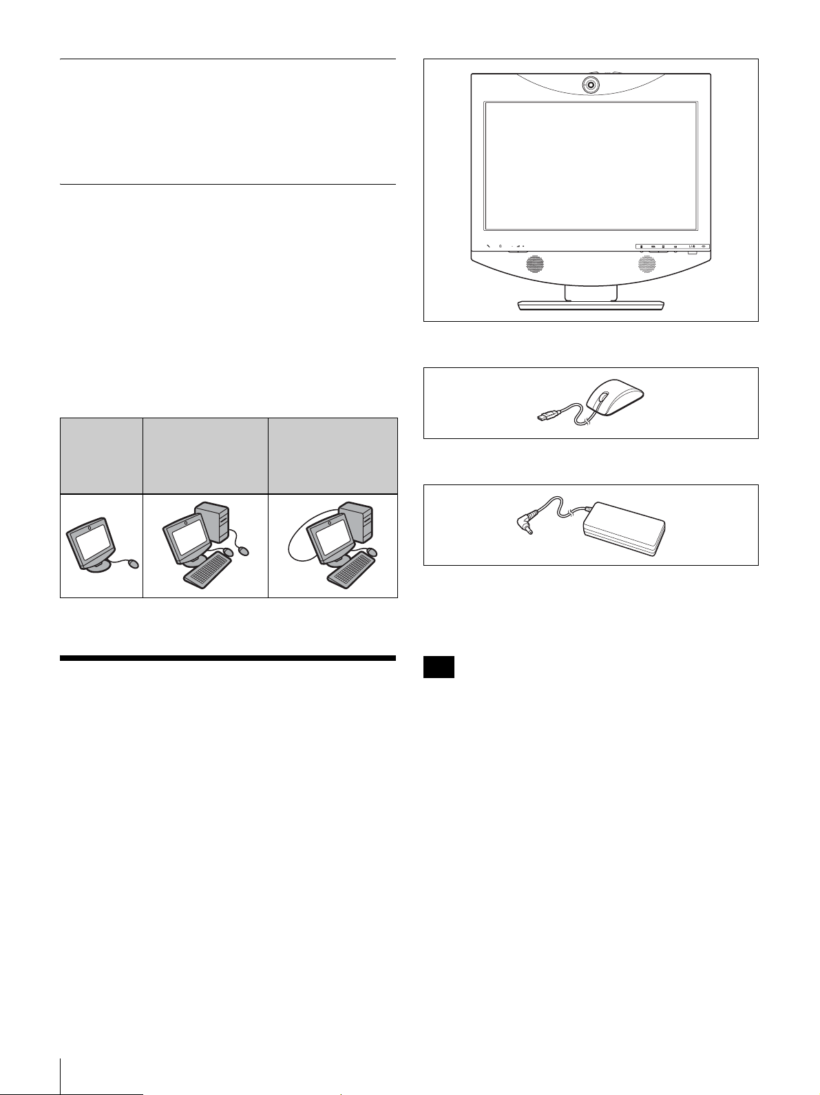
Interfaz de usuario intuitiva
La interfaz de usuario utiliza un diseño de capas que
permite al usuario controlar las operaciones con sólo hacer
clic en el ratón suministrado. También ofrece orientación
al usuario mediante mensajes, así como ayuda en línea.
Utilización como pantalla de
ordenador
Además de utilizarlo en modo autónomo, también es
posible conectar el sistema PCS-TL30 a un ordenador. En
este caso, puede utilizar ratones diferentes para el
ordenador y el sistema PCS-TL30, o utilizar un único ratón
para ambos.
El módulo de conexión de datos PCSA-DSM1, que se
puede adquirir por separado, permite transmitir el
contenido de la pantalla del ordenador a la ubicación
remota durante una videoconferencia.
• Ratón óptico PCS-RMU1 (1)
Utilización
en modo
autónomo
Utilización con un
ordenador y con
dispositivos
señaladores
independientes
Utilización con un
ordenador y un
único dispositivo
señalador
independiente
Comprobación del
contenido del paquete
Una vez desempaquetada la unidad, asegúrese de que se
encuentran todos los elementos siguientes:
• Unidad principal PCS-TL30 (1)
• Adaptador de ca PCS-AC19V6A o PCGA-AC19V7 (1)
• Cable de alimentación (1)
• Guía de inicio rápido (este documento) (1)
• CD-ROM (manual de instrucciones) (1)
• Folleto de garantía (1)
Nota
El CD-ROM suministrado contiene el manual de
instrucciones, que ofrece información detallada sobre los
procedimientos de manejo y los distintos ajustes. Estos
documentos se suministran en archivos en formato PDF.
68
Comprobación del contenido del paquete
Page 69
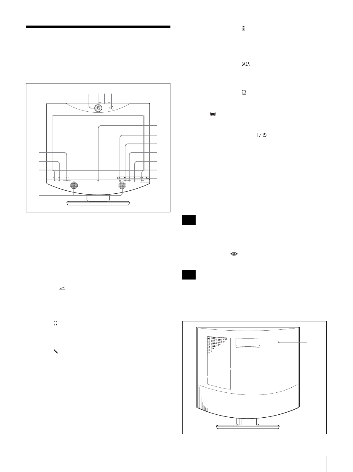
Nombres y funciones de
1 423
las piezas
Vista frontal
9
q;
qa
5
6
7
8
qs
qd
qf
qg
j Botón e indicador (micrófono desactivado).
Permite suprimir el sonido proveniente del sistema local.
Pulse el botón nuevamente para reanudar el envío del
sonido al sistema remoto.
k Botón e indicador (videoconferencia)
Permite pasar de la pantalla del ordenador a la pantalla de
la videoconferencia.
l Botón e indicador (ordenador)
Sirve para pasar a la pantalla del ordenador.
m Botón (menú)
Púlselo para que aparezca el menú Configuración.
n Interruptor e indicador (alimentación)
Conecta y desconecta la alimentación del sistema.
Cuando utilice el sistema como pantalla de un ordenador
en el modo PC, la alimentación se desactivará al pulsar una
vez el interruptor.
Cuando se utiliza el sistema en el modo de
videoconferencia, al pulsar el interruptor una vez el
sistema pasará al modo de espera. Para desactivar la
alimentación en el modo de videoconferencia, pulse el
interruptor nuevamente antes de que transcurran 5
segundos desde la primera pulsación.
a Lámpara indicadora
Se enciende al enviar vídeo local al sistema remoto.
b Objetivo de la cámara
c Palanca de la cubierta del objetivo de la cámara
d Micrófono
e Botones (volumen)
Permiten ajustar el volumen.
+: Aumenta el nivel de volumen.
-: Reduce el nivel de volumen.
f Toma (auriculares) (minitoma estéreo)
Permite conectar unos auriculares (disponible en el
mercado).
g Toma (micrófono) (minitoma)
Permite conectar el micrófono opcional PCS-A1 o PCSAA3.
h Altavoces
Nota
El interruptor de alimentación no funcionará mientras se
esté llevando a cabo una sesión de comunicación.
o Indicador del “Memory Stick”
Muestra el estado de la ranura para “Memory Stick”.
Nota
No extraiga el “Memory Stick” si el indicador está
encendido.
Vista posterior
1
i Lámpara en línea
Muestra principalmente el estado de las llamadas entrantes
y salientes.
Nombres y funciones de las piezas
69
Page 70
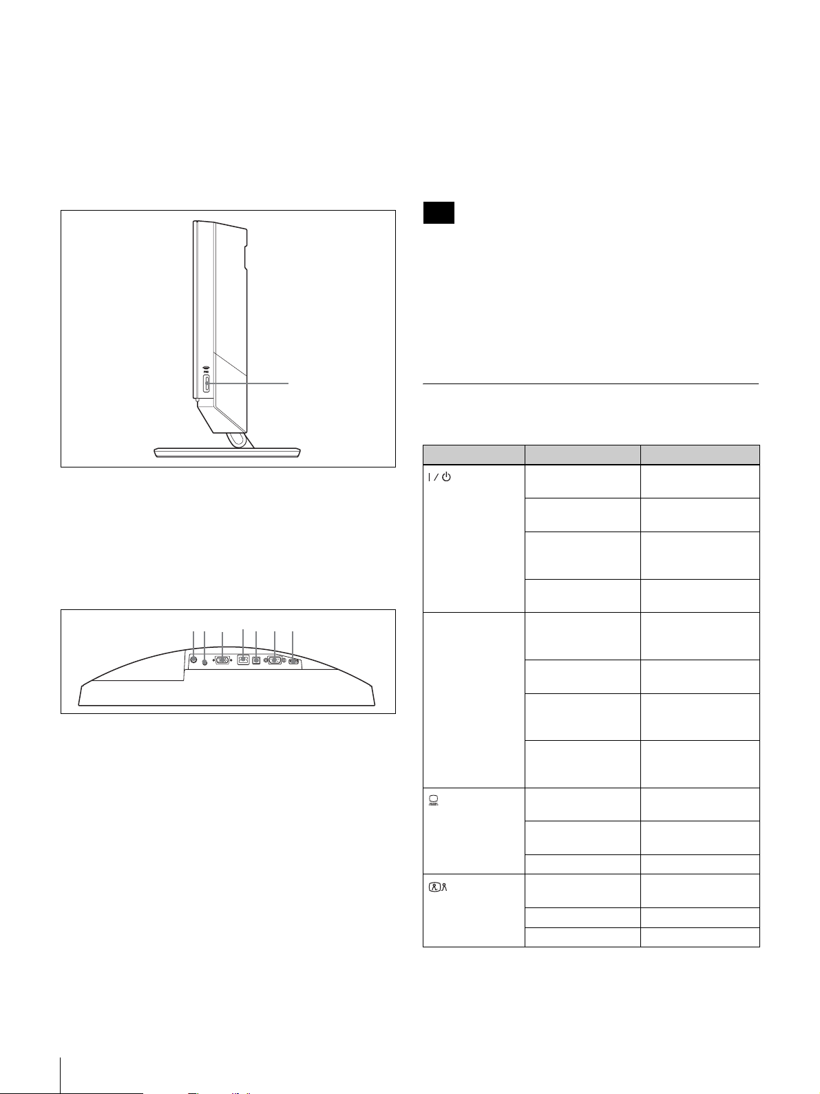
a Cubierta trasera
7653421
Si extrae la cubierta, obtendrá acceso al panel de
conectores. La sección de conexiones entre el soporte y la
pantalla también está situada detrás del panel. Es posible
cambiar la posición de los tornillos para ajustar la altura de
la pantalla.
Vista del lateral derecho
1
a Ranura para “Memory Stick”
Se puede insertar un “Memory Stick”.
Panel de conectores
(sección situada detrás de la cubierta
trasera vista desde abajo)
a Conector DC19,5V
Conecte el adaptador de ca suministrado PCS-AC19V6A
o PCGA-AC19V7 en este conector.
b Toma AUDIO IN (entrada de audio del ordenador)
(minitoma estéreo)
Permite la conexión de esta toma a la salida de audio de un
ordenador conectado al conector RGB IN.
c Conector RGB IN (conector mini D-sub de 15
terminales)
Permite conectar la salida RGB de un ordenador.
d Puerto 100BASE-TX/10BASE-T (RJ-45)
Utilice un cable LAN de categoría 5 para conectar este
puerto a un concentrador o a un equipo similar.
Este puerto está equipado con un indicador de Enlace/Datos
(verde) y un indicador de velocidad de 100/10 Mbps (naranja).
e Puerto del ordenador
Este conector se utiliza cuando se desea utilizar el mismo
ratón para el sistema PCS-TL30 y el ordenador conectado
al conector RGB IN. Conecte el conector a un puerto USB
del ordenador.
Nota
No utilice un cable USB de una longitud superior a 3 m.
f Puerto RS-232C (conector D-sub de 9 terminales)
Este conector se utiliza únicamente para llevar a cabo
reparaciones del sistema.
g Puerto del ratón
Permite conectar el ratón óptico PCS-RMU1 suministrado.
Nombres y funciones de los
indicadores
Indicador Estado Significado
(
alimentación
En línea * Parpadeo en azul
(ordenador) *
(videoconferencia)
Iluminado en verde La alimentación
) *
Iluminado en
naranja
Parpadeo en
naranja (ciclos de 1
segundo)
Apagado La alimentación
(3 veces por
segundo)
Iluminación en azul
encendida
Parpadeo
intermitente en
azul
Apagado
Iluminado en azul Pantalla de
Iluminado en
blanco
Apagado Espera
Iluminado en azul Pantalla de
*
Iluminado en blanco
Apagado Espera
está activada
Espera
Problema con el
ventilador
está desactivada
Enviando/
recibiendo
Comunicación en
curso
Indicación de
llamada perdida
Sin conexión (no hay
llamadas perdidas) o
en espera
ordenador
Pantalla de
videoconferencia
videoconferencia
Pantalla del ordenador
70
Nombres y funciones de las piezas
Page 71
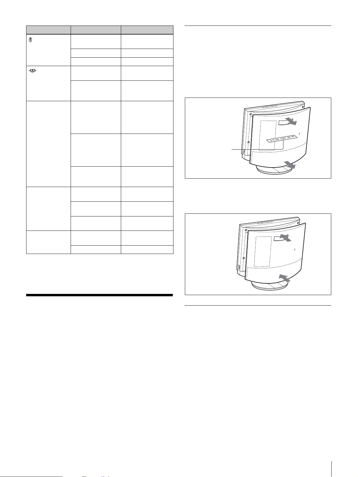
Indicador Estado Significado
(micrófono
desactivado) *
(“Memory
Stick”)
Lámpara
indicadora
Enlace/Datos Iluminado en verde Se ha establecido
100/10 Mbps Iluminado en
Iluminado en
naranja
Iluminado en blanco
Apagado Espera
Iluminado en
naranja
Apagado No se está
Iluminada en
naranja
Parpadeo en
naranja (ciclos de 5
segundos)
Apagada No se está
Parpadeo en verde Se están
Apagado El enlace no está
naranja
Apagado 10 Mbps
Micrófono
desactivado
Micrófono activado
Se está accediendo
al “Memory Stick”
accediendo al
“Memory Stick”
Se está enviando la
imagen de la cámara
a la ubicación remota
(cubierta del
objetivo)
Se está enviando la
imagen cerrada a la
ubicación remota
(cubierta del objetivo
cerrada)
enviando la imagen
de la cámara
un enlace
transfiriendo datos
conectado
100 Mbps
Acerca de los conectores
Los conectores del sistema están situados debajo de la
cubierta trasera. Retire la cubierta para realizar las conexiones
y, a continuación, vuelva a colocarla nuevamente.
Extracción de la cubierta trasera
Tire de la cubierta hacia usted.
Panel de conectores
(debajo de la
cubierta trasera)
Colocación de la cubierta trasera
Empuje la cubierta haciendo coincidir las cuatro lengüetas.
* El indicador se ilumina mientras el sistema se inicia. Si se detecta una
temperatura anormal, el indicador parpadea y se desactiva la alimentación.
Conexiones del sistema
Esta sección muestra algunos ejemplos representativos de
conexiones del sistema.
Además de utilizarlo en modo autónomo, también es
posible conectar el sistema PCS-TL30 a un ordenador para
usarlo como pantalla cuando no hay ninguna
videoconferencia en curso. En tal caso, es posible utilizar
ratones diferentes para el ordenador y el sistema PCSTL30 o conectar el sistema PCS-TL30 y el ordenador con
un cable USB genérico y utilizar el mismo ratón para
ambos.
Precauciones durante la conexión
Advertencia
• Utilice únicamente el adaptador de ca y el cable de
alimentación suministrados.
• Al conectar el cable de alimentación del adaptador de ca
y el cable de cc, introduzca las clavijas hasta el final y
con firmeza.
• Por motivos de seguridad, no conecte el conector
100BASE-TX/10BASE-T a una red en la que se puedan
producir voltajes excesivos.
Precaución
• Antes de realizar las conexiones, asegúrese de
desconectar la alimentación de todos los componentes.
• Para evitar daños en la unidad, no enchufe ni desconecte
ningún cable mientras la alimentación de la misma esté
activada.
Conexiones del sistema
71
Page 72
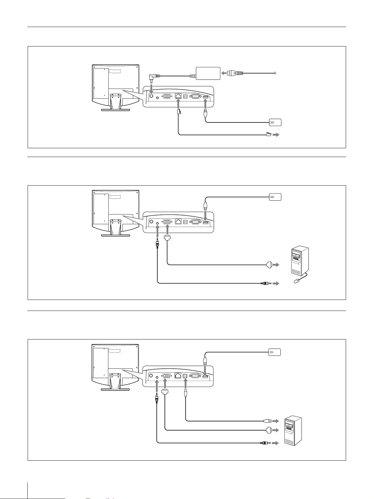
Ejemplo de conexión (utilización en modo autónomo)
Siga los pasos del 1 al 5 para realizar
las conexiones.
Sistema de
comunicaciones de
vídeo PCS-TL30
Al puerto 100BASE-TX/ 2
10BASE-T
3 Al conector
DC19,5V
Adaptador de ca PCS-AC19V6A
o PCGA-AC19V7
(suministrado)
1 Al puerto del ratón
Cable UTP de categoría 5 (cable recto, disponible en el mercado)
4 Cable de alimentación (suministrado)
5 A la toma de ca
(ca de 120 V)
Ratón óptico PCS-RMU1
(suministrado)
a la LAN
Ejemplo de conexión para utilizar la unidad con el ordenador (con ratón
independiente)
Ratón óptico PCS-RMU1
Sistema de
comunicaciones de
vídeo PCS-TL30
Al puerto del ratón
(suministrado)
A la toma AUDIO IN
Al conector RGB IN
Cable con conector mini D-sub
de 15 terminales (disponible
en el mercado)
Cable de audio con miniclavija
estéreo (disponible en el mercado)
A la salida RGB
A la salida de audio
Ordenador
Ejemplo de conexión para utilizar la unidad con el ordenador (con ratón
compartido)
Ratón óptico PCS-RMU1
Sistema de
comunicaciones de
vídeo PCS-TL30
A la toma
AUDIO IN
Al puerto del ratón
Al
conector
RGB IN
Al puerto del
ordenador
Cable USB (disponible
en el mercado) *
Al puerto USB
(suministrado)
72
Conexiones del sistema
una longitud superior a 3 m.
Cable con conector mini D-sub de 15
terminales (disponible en el mercado)
Cable de audio con miniclavija
estéreo (disponible en el mercado)
A la salida RGB
A la salida de audio* No utilice un cable USB de
Ordenador
Page 73
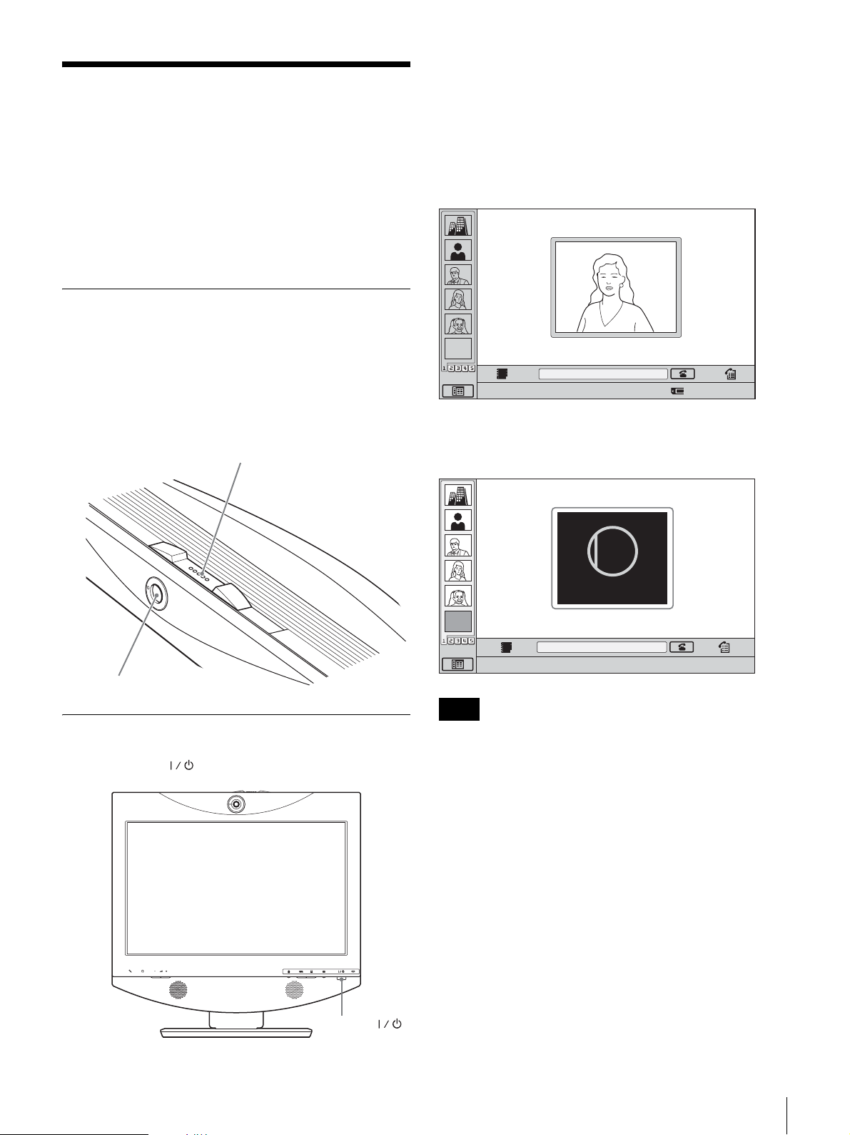
Encendido/apagado del
sistema
El indicador del interruptor se ilumina en naranja y el
Sistema de comunicaciones de vídeo empieza a recibir
alimentación. Cuando finalice el proceso de encendido, el
indicador se ilumina en verde. El menú de inicio aparece
en la pantalla y se muestra la imagen de la cámara local.
Antes de encender el sistema, asegúrese de que se han
realizado correctamente las conexiones.
En función del software que utilice, es posible que las
pantallas que aparezcan sean distintas de las que se
muestran aquí.
Apertura de la cubierta del objetivo
El sistema va equipado con una cubierta del objetivo para
ocultar la cámara. Antes de iniciar una videoconferencia,
abra la cubierta del objetivo deslizando hacia la derecha su
interruptor, situado en la parte superior del sistema. Si la
cubierta del objetivo está cerrada, la imagen de la
ubicación local no se verá en la ubicación remota.
Interruptor de la cubierta del objetivo
Menú de inicio
EMPTY
Haga clic en el icono para acceder a la función.
Cuando la cubierta del objetivo está cerrada, el menú de
inicio aparece como se indica a continuación.
CLOSED
Closed
Number :012.345.678.912
Cámara
Encendido del sistema
Pulse el interruptor (alimentación) del sistema PCS-TL30.
Interruptor
(alimentación)
EMPTY
Haga clic en el icono para acceder a la función.
Notas
Number :012.345.678.912
• Al pulsar por primera vez el interruptor de encendido
tras enchufar el cable de alimentación a la toma de pared,
es posible que el indicador del interruptor tarde diez
segundos en iluminarse.
• Al conectar la alimentación del Sistema de
comunicaciones de vídeo por primera vez tras la
instalación, aparece el asistente de configuración.
Configure el sistema siguiendo las indicaciones del
asistente.
Encendido/apagado del sistema
73
Page 74
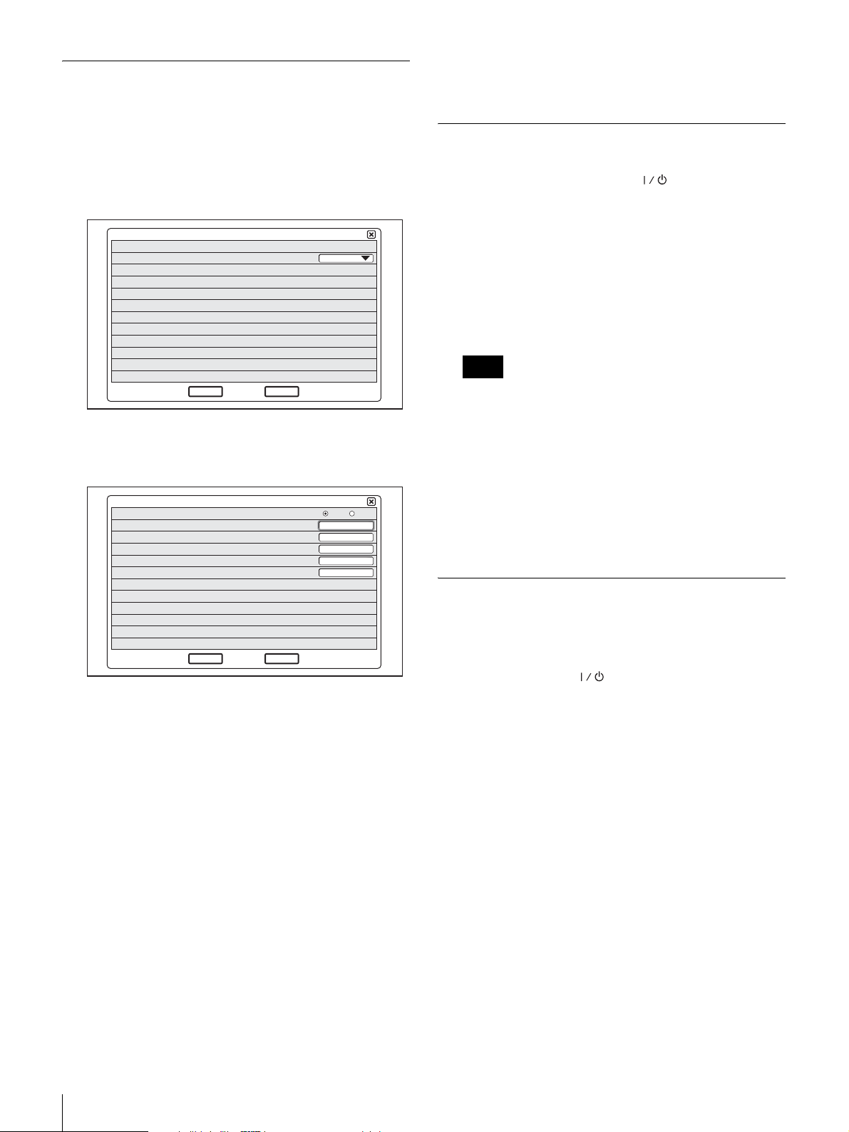
Asistente de configuración inicial
Algunos ajustes pueden variar ligeramente según el
software del monitor.
1
Acceda a la lista desplegable “Language” y seleccione
el idioma que desea que se utilice en los menús y
mensajes.
1/2
Language
Next
2
Haga clic en “Next”.
3
Realice los ajustes necesarios de la LAN.
Modo DHCP
Nombre del Host
Dirección IP
Máscara de red
Dirección Gateway
Dirección DNS
Cancel
English
2/2
Automático Desactivado
4
Haga clic en “Guardar”.
Se guardan los ajustes.
Apagado del sistema
1
Pulse dos veces el interruptor (alimentación).
Cuando haya pulsado el interruptor una vez, aparecerá
el mensaje “Para entrar en el modo de espera, espere
unos momentos. Para desconectar la alimentación,
vuelva a pulsar el interruptor de alimentación.”.
Vuelva a pulsar el interruptor de alimentación.
2
Desconecte la alimentación de los otros equipos
utilizados para la videoconferencia.
Notas
• Desconecte la alimentación del sistema cuando no
vaya utilizarlo durante un período prolongado de
tiempo. Cuando la alimentación se encuentra
desconectada, no se pueden recibir llamadas desde
una ubicación remota.
• Cuando utilice el sistema como pantalla de un
ordenador en modo PC, la alimentación se
desactivará al pulsar una vez el interruptor.
• El interruptor de alimentación no funciona mientras
se realiza una conferencia.
Guardar
Anterior
Modo DHCP: Ajusta el protocolo DHCP (Pynamic
Host Configuration Protocol).
Automático: Asigna automáticamente su
dirección IP, máscara de subred, dirección de
pasarela y dirección de DNS.
Desactivado: Desactiva el protocolo DHCP. En
este caso, ajuste manualmente su dirección IP,
máscara de subred, dirección de pasarela y
dirección de DNS.
Nombre del Host: Introduzca el nombre del sistema
principal.
Dirección IP: Introduzca su dirección IP.
Máscara de red: Introduzca la máscara de subred.
Dirección Gateway: Introduzca su dirección de
pasarela predeterminada.
Dirección DNS: Introduzca su dirección de servidor
DNS (Domain Name System).
Si no sabe qué ajustes debe realizar para configurar la
LAN, póngase en contacto con su administrador de red.
Ajuste del sistema de
comunicaciones de vídeo para el
modo de espera
Al pulsar el interruptor (alimentación) del sistema
PCS-TL30, aparecerá en la pantalla el mensaje “Para
entrar en el modo de espera, espere unos momentos. Para
desconectar la alimentación, vuelva a pulsar el botón de
alimentación.”. Si espera unos momentos sin realizar
ninguna acción, el sistema entrará en modo de espera.
Se puede recibir una llamada de la ubicación remota
mientras se encuentra en modo de espera.
Si desea volver al modo normal desde el modo de espera,
pulse una vez el interruptor de alimentación.
74
Encendido/apagado del sistema
Page 75
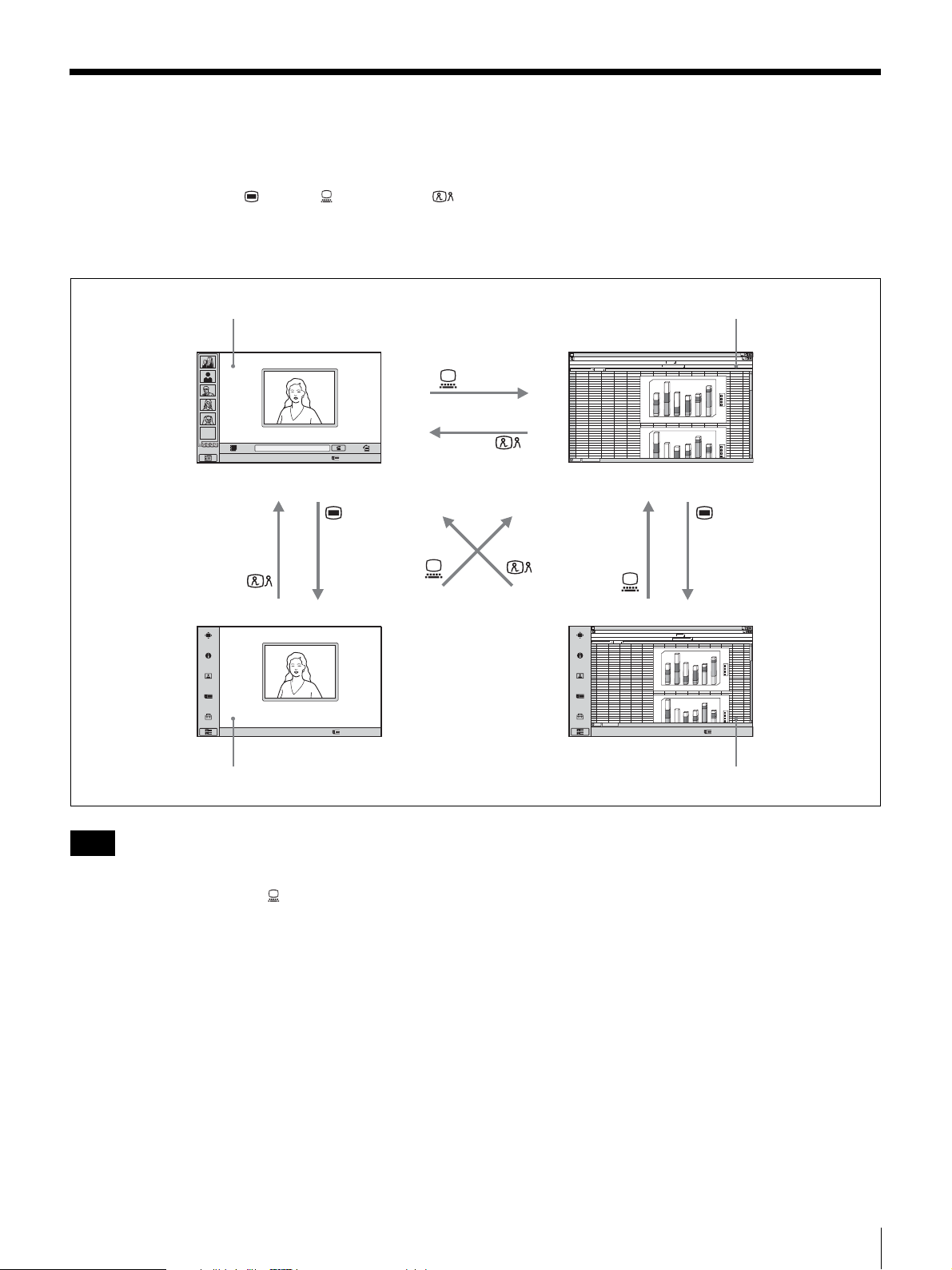
Cambio de la pantalla de videoconferencia a la
pantalla del ordenador
Puede utilizar los botones (menú), (ordenador) y
(videoconferencia) situados en la parte inferior derecha de
la unidad para alternar entre la pantalla de
videoconferencia y la pantalla del ordenador.
Pantalla de videoconferencia (menú de inicio) Pantalla del ordenador normal
ABCDEFGH IJ KLMN
1
abcd
2
EMPTY
Haga clic en el icono para acceder a la función.
Number :012.345.678.912
3
4
5
6
7
8
9
10
11
12
13
14
15
16
17
18
19
20
21
22
23
24
25
26
27
28
29
30
31
32
33
34
46
23
12
67
45
4
12
26
5
16
57
6
7
23
69
15
44
76
abcd
45
67
4
26
12
5
57
16
6
23
45
12
15
78
46
23
7
69
34
180
56
76
1
6
0
38
1
4
0
13
12
1
2
0
1
0
0
6
0
5
0
4
0
2
0
0
1
2
180
1
6
0
56
1
4
0
76
23
1
2
0
34
1
0
0
12
13
0
6
5
0
4
0
d
c
b
a
6
5
4
3
d
c
b
a
Haga clic en el icono para acceder a la función.
Number :012.345.678.912
Pantalla de videoconferencia (menú Configuración) Pantalla del ordenador (menú Configuración)
Notas
• Si el sistema PCS-TL30 no está conectado a un
ordenador y pulsa el botón (ordenador) para cambiar
a la pantalla del ordenador, se desactivará el ratón.
• Si se está mostrando una imagen secundaria durante una
sesión de comunicación, ésta permanecerá visible
cuando cambie a la pantalla del ordenador. Sin embargo,
el vídeo mostrado en la imagen secundaria procederá del
sistema remoto o del sistema local.
• Si se utilizan ratones independientes para el sistema
PCS-TL30 y el ordenador, el ratón que se encuentre
activo en esos momentos dependerá de la pantalla
conectada. El ratón conectado al ordenador estará activo
mientras se muestre la pantalla del ordenador normal,
mientras que el ratón conectado al sistema PCS-TL30
estará activo cuando se muestren otras pantallas.
ABCDEFGH IJ KLMN
1
2
abcd
3
12
46
23
34
4
4
5
5
6
6
7
69
8
44
9
10
11
12
13
14
15
16
17
18
19
20
21
22
23
24
25
abcd
26
4
27
5
28
6
29
12
30
46
31
69
32
33
34
Haga clic en el icono para acceder a la función.
180
67
45
56
12
26
76
1
6
0
16
57
38
4
0
1
7
23
13
76
15
12
2
0
1
0
1
0
6
0
5
0
0
4
0
2
0
1
2
180
6
0
1
67
45
56
4
0
1
12
26
76
16
57
23
2
0
1
45
23
34
0
0
1
78
15
12
7
23
13
6
0
5
0
4
0
3
5
4
d
c
b
a
6
d
c
b
a
Number :012.345.678.912
Cambio de la pantalla de videoconferencia a la pantalla del ordenador
75
Page 76
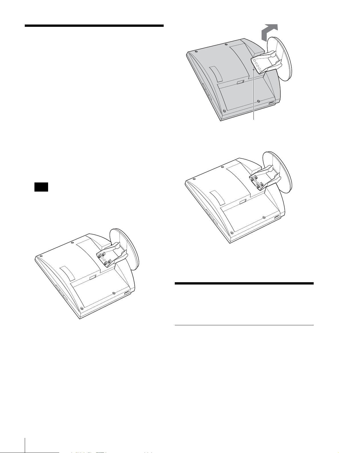
Ajuste de la altura de la
pantalla
El soporte y la sección de la pantalla del sistema PCSTL30 están unidos mediante tornillos de sujeción. Hay tres
conjuntos de orificios para los tornillos, separados entre sí
por 25 mm. La pantalla viene fijada en la posición más baja
de fábrica. Seleccione un conjunto de orificios para los
tornillos distinto para modificar la altura de la pantalla.
1
Retire la cubierta trasera de la unidad.
Perno de posicionamiento
Para obtener información sobre cómo retirarla,
consulte la página 71.
2
Extraiga los cuatro tornillos utilizando una moneda u
objeto similar, levante el soporte e introduzca el perno
de posicionamiento en el orificio correspondiente para
fijar la nueva posición.
Nota
Antes de cambiar la altura de la pantalla tal y como se
ha descrito anteriormente, asegúrese de desconectar la
alimentación. Coloque la pantalla cara abajo sobre un
paño suave o similar.
3
Apriete los cuatro tornillos utilizando una moneda u
objeto similar para fijar la posición.
4
Vuelva a colocar la cubierta trasera.
Para obtener un mejor
76
Ajuste de la altura de la pantalla / Para obtener un mejor rendimiento
rendimiento
Ubicación de funcionamiento o
almacenamiento
Evite utilizar o almacenar el sistema en las siguientes
ubicaciones:
• Lugares extremadamente cálidos o fríos
• Lugares húmedos o con polvo
• Lugares expuestos a fuertes vibraciones
• Lugares cercanos a fuentes de magnetismo intenso
• Lugares cercanos a fuentes de radiación
electromagnética intensa, como radios o transmisores de
televisión.
• Lugares con muchas interferencias
Page 77

Pantalla de cristal líquido
• No exponga la superficie de la pantalla de cristal líquido
al sol, ya que de lo contrario es posible que se dañe la
superficie de la misma.
• No empuje ni raye la pantalla de cristal líquido ni
coloque objetos sobre el sistema. Es posible que la
imagen pase a visualizarse de manera irregular o que la
pantalla de cristal líquido se dañe.
• Si se utiliza el sistema en un lugar frío, es posible que la
imagen se oscurezca o que aparezca una mancha en la
pantalla. No se trata de un fallo de funcionamiento. Estos
fenómenos se solucionan a medida que la temperatura
aumenta.
• Si se visualizan imágenes fijas continuamente, es posible
que se produzca un efecto de imagen fantasma, que
desaparecerá transcurridos unos segundos.
• Al utilizar el sistema, la pantalla y la unidad se calientan.
Esto no es un fallo de funcionamiento.
Panel de la pantalla de cristal líquido
Aunque el panel de la pantalla de cristal líquido está
fabricado con tecnología de alta precisión, es posible que
aparezcan puntos negros o brillantes (rojo, azul o verde)
constantemente en la pantalla. También es posible que
aparezcan rayas de color y un brillo irregular si visualiza la
pantalla desde determinados ángulos de visión. No se trata
de un fallo de funcionamiento, sino que es una
característica de la estructura del panel de cristal líquido.
Altavoces incorporados
Los altavoces generan magnetismo. Para evitar dañar los
datos, mantenga las cintas magnéticas y los discos alejados
de los altavoces.
Limpieza
• Antes de limpiar la unidad, desconecte el cable de
alimentación del sistema PCS-TL30 de la toma de ca.
• La superficie de la pantalla de cristal líquido cuenta con
un acabado especial. Para eliminar el polvo de la
superficie de la pantalla, límpiela cuidadosamente con
un paño suave y seco.
• No utilice disolventes como alcohol, bencina o
diluyentes, ya que pueden dañar o decolorar el acabado
de la superficie.
• Si utiliza paños de limpieza químicos, consulte las
medidas de precaución para el usuario suministradas con
los mismos.
• No aplique sustancias volátiles como insecticidas a la
unidad ni permita que objetos de goma o plástico toquen la
unidad durante un período de tiempo prolongado, ya que
podrían dañar o decolorar el acabado de la superficie.
Especificaciones
Sistema de comunicaciones de vídeo PCSTL30
Esta unidad cumple con las recomendaciones H.323 e
IETF SIP de la ITU-T.
Imagen en movimiento
Ancho de banda operativo
de 64 kbps a 2.048 kbps
Codificación H.261/H.263/H.263+/H.263++/H.264
(Recomendación de la ITU-T)
MPEG4 Simple Profile
Elementos de imagen
CIF: 352 píxeles × 288 líneas
QCIF: 176 píxeles × 144 líneas
Imagen fija
Píxeles 704 píxeles × 576 líneas
Codificación H.261 (Recomendación de la ITU-T)
Anexo. D (4CIF)
H.263 (formato especial de este sistema)
Sonido
Ancho de banda 14 kHz (audio MPEG4)
7 kHz (G.722 compatible con las
recomendaciones de la ITU-T)
3,4 kHz (G.711/G.728/G.729 compatible
con las recomendaciones de la ITU-T)
Velocidad de transmisión
64 kbps, 96 kbps (audio MPEG4)
56 kbps, 64 kbps (G.711 compatible con
las recomendaciones de la ITU-T)
48 kbps, 56 kbps, 64 kbps (G.722
compatible con las recomendaciones
de la ITU-T)
16 kbps (G.728 compatible con las
recomendaciones de la ITU-T)
8 kbps (G.729 compatible con las
recomendaciones de la ITU-T)
Red
Multiplex Vídeo, audio, datos
Formato de fotograma
H.225.0 (compatible con las
recomendaciones de la ITU-T)
Interfaz LAN (100BASE-TX/10BASE-T)
Protocolo LAN admitido
HTTP
FTP
Telnet
RTP/RTCP
TCP/UDP
IP
Especificaciones
77
Page 78

Mando a distancia
Control de cámara lejana
H.281 (compatible con las
recomendaciones de la ITU-T)
Cámara
Dispositivo de imagen
CMOS en color de 1/3,2 pulgadas
(píxeles efectivos totales: aprox. 1,3
millones)
Objetivo f = 2,3 mm
F = 1:2,8
Ángulo horizontal: aprox. 88°
Ángulo vertical: aprox. 73°
Distancia focal 300 mm
Función de pantalla panorámica/inclinación/zoom
Mediante procesamiento digital
Función de equilibrio automático del blanco integrada
Velocidad de fotograma
30/15 fps, cambio automático para
ajustarse a la iluminación ambiental
Pantalla
Tamaño Tipo 17,1 panoramico
Resolución 1.280 × 768 (WXGA)
Tiempo de respuesta
13 ms o inferior
Índice de contraste
600:1
Ángulo de visión
176 grados o superior
Número de colores
16.700.000 colores
Controlador de pantalla
PinP 4 esquinas
PandP Tres ventanas
Entrada Interna: Comunicación por vídeo
RGB externa: Pantalla de ordenador
Modo panorámico
Normal, Zoom, Panorámico
Modo RGB 640 × 480, 800 × 600, 1024 × 768,
1280 × 768, etc.
Se puede visualizar la imagen ampliada/
reducida.
Altavoz
Altavoz 3 W × 2
Micrófono
Intervalo de frecuencia
14 kHz
Característica direccional
Direccional con ángulo cerrado
Generales
Alimentación eléctrica
19,5 V
Consumo de energía
6,15 A
Temperatura de funcionamiento
De 5 a 35°C
Humedad de funcionamiento
Del 20 al 80%
Temperatura de almacenamiento
De –20 a +60°C
Humedad de almacenamiento
Del 20 a 80% (sin condensación)
Dimensiones 424 × 376 × 95,5 mm (an/al/prf)
(sin incluir el soporte)
424 × 419 × 258 mm (an/al/prf)
(incluido el soporte)
Peso Aprox. 8 kg
Accesorios suministrados
Ratón óptico PCS-RMU1 (1)
Adaptador de ca PCS-AC19V6A/PCGA-
AC19V7 (1)
Cable de alimentación (1)
CD-ROM (1)
Guía de inicio rápido (1)
Folleto de garantía (1)
Adaptador de ca PCS-AC19V6A o PCGAAC19V7
Alimentación eléctrica
ca de 100 a 240 V, 50/60 Hz, 1,8 A
Salida 19,5 V, 6,15 A
Temperatura de funcionamiento
De 5 a 35 °C
Humedad de funcionamiento
Del 20 al 80%
Temperatura de almacenamiento
De –20 a +60 °C
Humedad de almacenamiento
Del 20 al 80% (sin condensación)
Dimensiones 80 × 40 × 160 mm (an/al/prf)
Peso Aprox. 800 g
Micrófono PCS-A1 (opcional)
Ancho de banda 13 kHz
Característica direccional
Omnidireccional
Dimensiones 74 × 16 × 93 mm (an/al/prf)
Peso Aprox. 170 g
Alimentación Por enchufe
Micrófono PCSA-A3 (opcional)
Ancho de banda 13 kHz
Característica direccional
Unidireccional
Dimensiones 68 × 16 × 96 mm (an/al/prf)
Peso Aprox. 200 g
Alimentación Por enchufe
78
Especificaciones
Page 79
Módulo de conexión de datos PCSA-DSM1
(opcional)
Consumo de energía
Máximo de 20 W
Temperatura de funcionamiento
De 5 a 35°C
Humedad de funcionamiento
Del 20 al 80%
Temperatura de almacenamiento
De –20 a +60°C
Humedad de almacenamiento
Del 20 al 80% (sin condensación)
Dimensiones 107 × 250 × 34 mm (an/al/prf)
(excluyendo las partes que sobresalen)
Peso Aprox. 550 g
Accesorios suministrados
Guía de inicio rápido (1)
Folleto de garantía (1)
Software SIP PCSA-SP1 (opcional)
Accesorios suministrados
Precinto de número de serie (1)
Manual de instrucciones (1)
El diseño y las especificaciones están sujetos a cambios sin
previo aviso.
El cancelador de eco de la unidad se ha desarrollado con
licencia de Nippon Telegraph and Telephone
Corporation. Nippon Telegraph and Telephone
Corporation también posee el copyright del software
cancelador de eco.
Queda prohibida la utilización o venta de las tecnologías
empleadas en la unidad en su totalidad o en parte para
armas o para la fabricación de éstas. Todos los derechos
del software incorporado en la unidad y las copias de la
documentación correspondiente pertenecen a Nippon
Telegraph and Telephone Corporation y a Sony. Queda
prohibido copiar, realizar ingeniería inversa,
descompilar, desmontar y modificar las tecnologías
incorporadas en la unidad.
Este producto utiliza fuentes de mapas de bits de Ricoh
producidas y comercializadas por Ricoh Co., Ltd.
Especificaciones de la entrada o salida RGB
Elemento de imagen Formato de señal fH (kHz) fV (Hz) Frecuencia de
exploración (MHz)
640 × 480 Modo VGA 31,469 59,94 25,17 H-neg V-neg
Macintosh 13" 35 66,667 30,24 H-neg V-neg
VGA VESA 72 Hz 37,861 72,809 31,5 H-neg V-neg
VGA VESA 75 Hz 37,5 75 31,5 H-neg V-neg
VGA VESA 85 Hz 43,269 85,008 36 H-neg V-neg
800 × 600 SVGA VESA 56 Hz 35,156 56,25 36 H-pos V-pos
SVGA VESA 60 Hz 37,879 60,317 40 H-pos V-pos
SVGA VESA 72 Hz 48,077 72,188 50 H-pos V-pos
SVGA VESA 75 Hz 46,875 75 49,5 H-pos V-pos
SVGA VESA 85 Hz 53,674 85,061 56,25 H-pos V-pos
1024 × 768 XGA VESA 60 Hz 48,363 60,004 65 H-neg V-neg
XGA VESA 70 Hz 56,476 70,069 75 H-neg V-neg
XGA VESA 75 Hz 60,023 75,029 78,75 H-pos V-pos
1280 × 768 WXGA VESA 60 Hz* 47,693 59,992 80,12 H-neg V-pos
* No puede transmitirse a través del módulo de conexión de datos PCSA-DSM1.
Sincronización
Especificaciones
79
Page 80

Italiano
ATTENZIONE
Per ridurre il rischio di incendi o scosse
elettriche, non esporre questo prodotto
alla pioggia o all’umidità.
Per evitare scosse elettriche, non aprire
l’apparecchio.
Per eventuali riparazioni, rivolgersi
esclusivamente a personale qualificato.
ATTENZIONE
Per l’alimentazione elettrica utilizzare l’adattatore CA
fornito in dotazione all’apparecchiatura.
Viene fornito uno degli adattatori di alimentazione CA
elencati di seguito.
Produttore Sigla modello
Sony PCS-AC19V6A
Sony PCGA-AC19V7
L’utilizzo di qualsiasi altro alimentatore comporta rischi,
in particolare pericolo di incendi.
Il sezionatore di questa apparecchiatura è la spina di
alimentazione dell’adattatore CA.
Per scollegare l’alimentazione elettrica è necessario
utilizzare la spina di questa apparecchiatura.
Assicurarsi che la presa di corrente si trovi accanto
all’apparecchiatura e sia facilmente accessibile.
In caso di anomalie, scollegare la spina di alimentazione.
AVVISO
Utilizzare il cavo di alimentazione approvato
dall’organizzazione di prova specifica del paese in cui
verrà utilizzata l’unità.
AVVERTENZA relativa alla porta LAN
Per ragioni di sicurezza, non collegare la porta LAN ad
alcun dispositivo di rete che potrebbe avere una tensione
eccessiva.
Per gli acquirenti in Europa
Attenzione
Questo è un apparecchio di classe A e come tale, in un
ambiente domestico, può causare interferenze radio. È
necessario quindi che l’utilizzatore adotti gli accorgimenti
adequati.
Nel caso si verifichino interferenze, rivolgersi ad un centro
assistenza Sony autorizzato.
80
Page 81
Sommario
Documentazione fornita ...........................82
Caratteristiche ...........................................82
Sistema di comunicazione video mobile
integrato............................................. 82
Interfaccia utente intuitiva .......................... 83
Utilizzo come display del computer ........... 83
Verifica del contenuto della confezione..83
Nomi e funzioni delle parti........................84
Nomi e funzioni degli indicatori................. 85
Connessioni del sistema ..........................86
Informazioni sui connettori......................... 86
Precauzioni per il collegamento.................. 86
Esempio di collegamento (utilizzo come unità
indipendente)..................................... 87
Esempio di collegamento per utilizzo con
computer (mouse separato) ............... 87
Esempio di collegamento per utilizzo con
computer (mouse in condivisione).... 87
Inserimento e disinserimento del sistema . 88
Apertura del coperchio dell’obiettivo......... 88
Accensione del sistema............................... 88
Installazione guidata ................................... 89
Spegnimento del sistema ............................ 89
Impostazione del sistema di comunicazione
video in modalità standby ................. 89
Commutazione tra schermo
videoconferenza e schermo
computer .............................................90
Regolazione dell’altezza dello schermo..91
Per ottenere le migliori prestazioni .........91
Luoghi in cui attivare o conservare il
sistema............................................... 91
Schermo LCD............................................. 92
Display LCD............................................... 92
Altoparlanti incorporati .............................. 92
Pulizia ......................................................... 92
Caratteristiche tecniche............................92
Dati tecnici ingresso/uscita RGB................ 94
Questa Guida introduttiva contiene importanti norme di
sicurezza e istruzioni per il maneggio del prodotto aventi
lo scopo di prevenire incidenti o infortuni. Per essere certi
di utilizzare il prodotto in modo sicuro, leggere con
attenzione questa Guida e conservarla per consultarla in
seguito.
Consultare inoltre le istruzioni per l’uso memorizzate nel
CD-ROM in dotazione. Esse contengono altre
informazioni dettagliate su questo prodotto. Consultare
questo documento assieme alla Guida introduttiva.
IT
Sommario
81
Page 82
Documentazione fornita
Questo prodotto viene fornito con diversi documenti,
elencati di seguito. Consultare gli opportuni documenti in
base alle proprie esigenze.
Guida introduttiva (questo documento)
Fornisce informazioni di base sulle impostazioni iniziali e
sui collegamenti del sistema. (Il CD-ROM in dotazione
contiene un file con la stessa Guida introduttiva.)
Istruzioni per l’uso (su CD-ROM in dotazione)
Fornisce informazioni dettagliate sulle procedure
operative e sulle impostazioni necessarie per effettuare
vari tipi di sessioni di videoconferenza. Tutte le funzioni
del prodotto sono trattate in questo documento.
Requisiti operativi per l’uso del CD-ROM
Per l’uso del CD-ROM devono essere soddisfatti i seguenti
requisiti di sistema.
• Computer: Dotato di processore Intel
- RAM: 64 MB o più
- Unità CD-ROM: velocità
• Schermo: Risoluzione 800
• Sistema operativo: Microsoft
Professional o Windows XP Home Edition
Se i suddetti requisiti non sono soddisfatti, il
funzionamento dell’unità CD-ROM può essere lento o
impossibile.
×8 o superiore
× 600 o superiore
®
®
Pentium®
Windows® XP
Visualizzazione delle Istruzioni per l’uso
1
Inserire il CD-ROM in dotazione con etichetta
“Manuals for VIdeo Communication System”
nell’unità CD-ROM del computer.
Dopo un certo tempo viene visualizzato sullo schermo
un elenco del contenuto del CD-ROM.
2
Fare doppio clic sul PDF con il nome file “Italiano”.
Viene così avviato Adobe Reader e viene visualizzata
la prima pagina delle Istruzioni per l’uso per il sistema
di comunicazione video.
Facendo clic su una voce della sezione “Contenuto” è
possibile saltare direttamente alla pagina
corrispondente.
• Adobe e Adobe Reader sono marchi di fabbrica di Adobe Systems
Incorporated.
• Microsoft e Windows sono marchi registrati di Microsoft Corporation
negli Stati Uniti e in altre nazioni.
• Intel e Pentium sono marchi di fabbrica o marchi registrati di Intel
Corporation o delle sue consociate negli Stati Uniti e in altre nazioni.
• “IPELA” e sono marchi di fabbrica di Sony
Corporation.
Caratteristiche
Operazioni preliminari
Per accedere alle istruzioni per l’uso sul CD-ROM in
dotazione, occorre che sul computer sia installata una delle
seguenti applicazioni:
• Adobe
• Adobe Reader versione 6.0 o successiva
Nota
Se Adobe Reader non è installato, è possibile scaricarlo dal
seguente URL:
http://www.adobe.com
®
Acrobat® versione 4.0 o successiva
Il PCS-TL30 sistema di comunicazione video è un sistema
per videoconferenze che consente di effettuare
comunicazioni normali vis-à-vis con un partecipante
remoto, con ricetrasmissione di immagini e audio tramite
una rete. Il partecipante remoto può trovarsi in qualsiasi
parte del mondo.
Sistema di comunicazione video
mobile integrato
Tutti gli elementi necessari del sistema di comunicazione
video, compresa la telecamera, il monitor, il codec, i
microfoni e gli altoparlanti, sono integrati in un unico
apparecchio dalle dimensioni contenute. Ciò facilita il
trasporto del sistema e consente di predisporre una
videoconferenza quasi ovunque ci si trovi.
Il display incorporato da tipo 17 supporta la modalità
Ampio. La telecamera incorporata è dotata di zoom e
panoramica/inclinazione digitali.
82
Documentazione fornita / Caratteristiche
Page 83
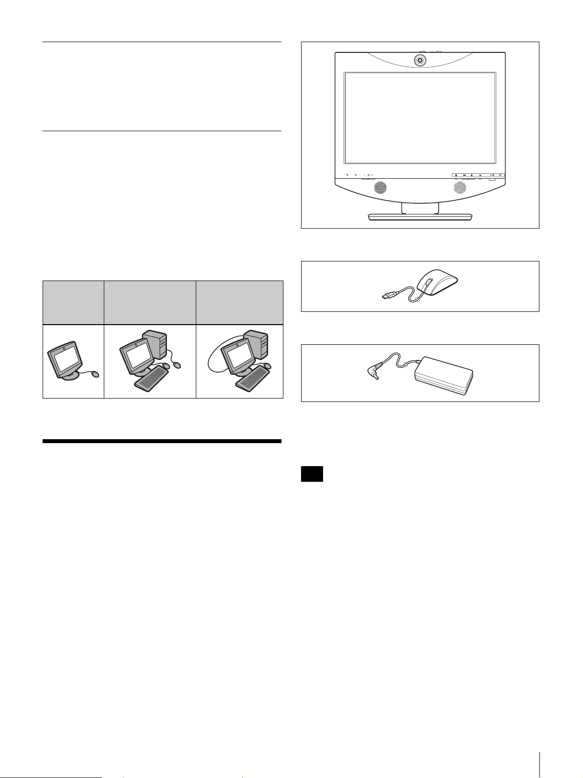
Interfaccia utente intuitiva
L’interfaccia utente utilizza uno schema a sovrapposizione
che permette di controllare le operazioni con un semplice
clic del mouse in dotazione. Viene anche fornita una guida
dell’utente, sotto forma di messaggi e di guida in linea.
Utilizzo come display del computer
Oltre a utilizzare l’apparecchio come unità indipendente, è
possibile collegare il PCS-TL30 a un computer. In questo
caso è possibile utilizzare due mouse diversi per il
computer e per il PCS-TL30, o utilizzare un unico mouse
per entrambi.
Il Data Solution Module PCSA-DSM1, disponibile a parte,
consente di trasmettere il contenuto dello schermo del
computer al partecipante remoto durante una
videoconferenza.
• Mouse ottico PCS-RMU1 (1)
Utilizzo
come unità
indipendente
Utilizzo con un
computer e due
dispositivi di
puntamento distinti
Utilizzo con un
computer e un
singolo dispositivo
di puntamento
Verifica del contenuto
della confezione
Una volta tolto il sistema dalla confezione, verificare che
siano presenti tutti i seguenti componenti:
• PCS-TL30 unità principale (1)
• Adattatore CA PCS-AC19V6A o PCGA-AC19V7 (1)
• Cavo di alimentazione (1)
• Guida introduttiva (questo documento) (1)
• CD-ROM (Istruzioni per l’uso) (1)
• Opuscolo di garanzia (1)
Nota
Il CD-ROM in dotazione contiene le Istruzioni per l’uso,
che forniscono informazioni dettagliate sulle procedure
operative e tutte le impostazioni. Tali documenti vengono
forniti come file in formato PDF.
Verifica del contenuto della confezione
83
Page 84
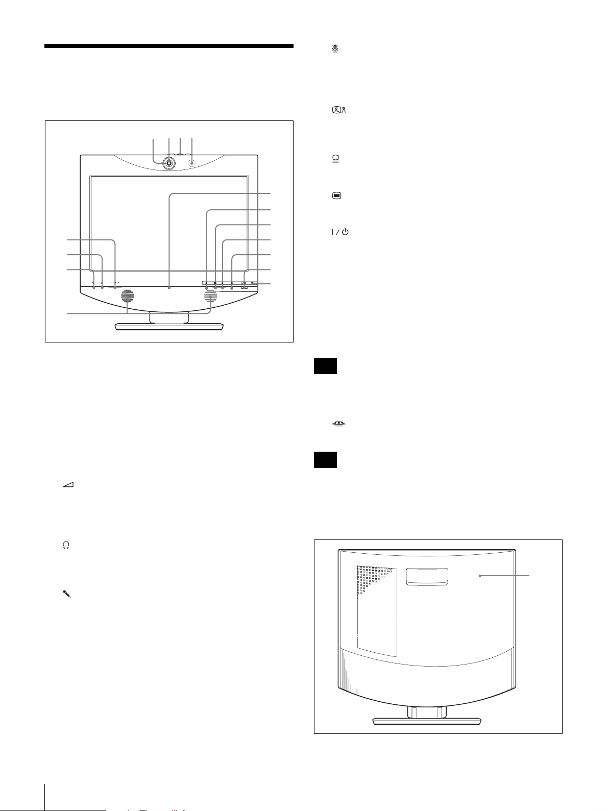
Nomi e funzioni delle parti
1 423
j Tasto Mic Off e indicatore
Consente di sopprimere il suono proveniente dal sistema
locale. Premere nuovamente il tasto per inviare
nuovamente l’audio al sistema remoto.
Vista frontale
9
q;
qa
5
6
7
8
a Lampada Tally
Si accende quando il segnale video locale viene inviato al
sistema remoto.
b Obiettivo telecamera
c Leva per coperchio obiettivo telecamera
qs
qd
qf
qg
k Tasto (Videoconferenza) e indicatore
Serve per commutare dallo schermo del computer allo
schermo di videoconferenza.
l Tasto (PC) e indicatore
Serve per commutare allo schermo del computer.
m Tasto (Menu)
Premere questo tasto per accedere al menu Impostazioni.
n Interruttore (alimentazione) e indicatore
Permette di accendere e spegnere il sistema.
Quando si utilizza il sistema come schermo computer in
modalità PC, basta premere una volta l’interruttore per
spegnere.
Quando si utilizza il sistema in modalità VC, basta
premere una volta l’interruttore per attivare la modalità
standby. Per spegnere in modalità VC, premere
nuovamente l’interruttore entro 5 secondi dalla prima volta
che lo si è premuto.
Nota
L’interruttore di alimentazione è disattivato durante una
sessione di comunicazione.
o Indicatore “Memory Stick”
Mostra lo stato dell’alloggiamento “Memory Stick”.
d Microfono
e Tasti (Volume)
Servono a regolare il volume.
+: Per aumentare il volume.
-: Per diminuire il volume.
f Jack (Cuffie) (mini jack stereo)
Consente di collegare un paio di cuffie (disponibile in
commercio).
g Jack (Mic) (mini jack)
Consente di collegare il microfono opzionale PCS-A1 o
PCSA-A3.
h Altoparlanti
i Indicatore Online
Mostra soprattutto lo stato delle chiamate in arrivo/in
uscita.
Nota
Non rimuovere la “Memory Stick” quando questo
indicatore è acceso.
Vista posteriore
1
84
Nomi e funzioni delle parti
Page 85
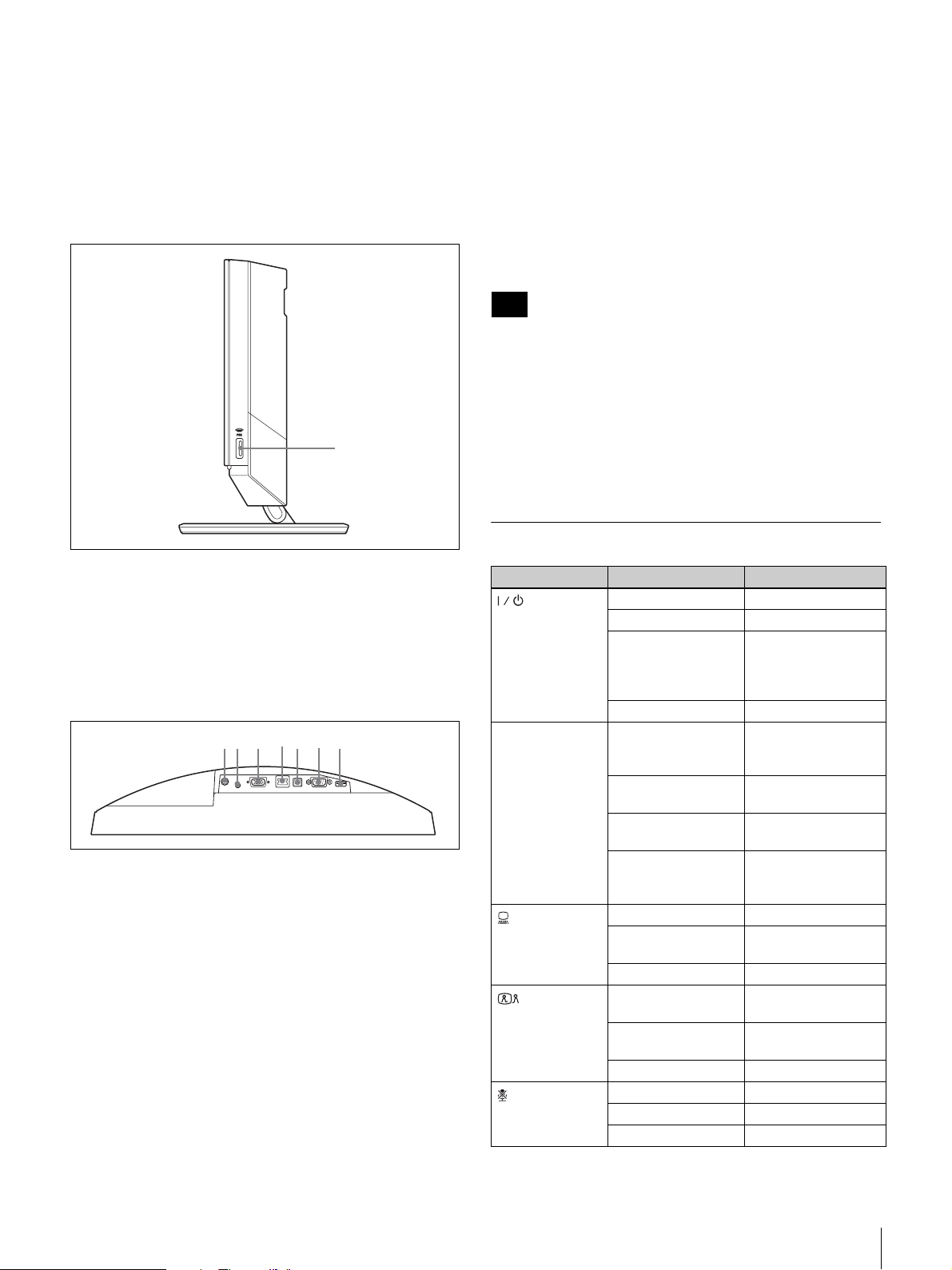
a Coperchio posteriore
7653421
La rimozione di questo coperchio permette di accedere al
pannello dei connettori. Dietro al pannello si trova anche
la sezione di collegamento tra il supporto e lo schermo. È
possibile regolare l’altezza dello schermo modificando le
posizioni delle viti.
Vista lato destro
1
d Porta 100BASE-TX/10BASE-T (RJ-45)
Utilizzare un cavo LAN Categoria 5 per collegare questa
porta a uno hub o un dispositivo simile.
Questa porta è dotata di un indicatore Link/Data (luce
verde) e un indicatore 100/10 Mbps (arancione).
e Porta PC
Questo connettore viene utilizzato quando si adopera lo
stesso mouse per il PCS-TL30 e per un computer collegato
al connettore RGB IN. Collegare il connettore a una porta
USB del computer.
Nota
Non utilizzare un cavo USB di lunghezza superiore a 3 m
(9,84 piedi).
f Porta RS-232C (connettore D-sub a 9 piedini)
Questo connettore viene utilizzato unicamente per la
manutenzione del sistema.
g Porta mouse
Collegare qui il mouse ottico PCS-RMU1 in dotazione.
a Alloggiamento “Memory Stick”
Qui è possibile inserire una “Memory Stick”.
Pannello dei connettori
(sezione sotto il coperchio posteriore,
vista dal di sotto)
a Connettore DC19,5V
Collegare qui l’adattatore CA PCS-AC19V6A o PCGAAC19V7 in dotazione.
b Jack AUDIO IN (ingresso audio PC) (mini jack
stereo)
Collegare questo jack all’uscita audio di un computer
collegato al connettore RGB IN.
c Connettore RGB IN (connettore mini D-sub a 15
piedini)
Collegare qui l’uscita RGB del computer.
Nomi e funzioni degli indicatori
Indicatore Stato Significato
Alimentazione
(
Online *
(PC) *
(Videoconferenza)
(Mic off) *
Luce verde Apparecchio acceso
) *
Luce arancione Standby
Luce arancione
lampeggiante
(intervalli di 1
secondo)
Spento Apparecchio spento
Luce blu
lampeggiante
(3 volte al secondo)
Luce blu Comunicazione in
Luce blu
intermittente
Spento Offline (nessuna
Luce blu Display computer
Luce bianca Schermo
Spento Standby
Luce blu Schermo
*
Luce bianca Display del
Spento Standby
Luce arancione Microfono spento
Luce bianca Mic on
Spento Standby
Problema con la
ventola
Invio/ricezione
corso
Indicazione
chiamata perduta
chiamata perduta) o
Standby
videoconferenza
videoconferenza
computer
Nomi e funzioni delle parti
85
Page 86
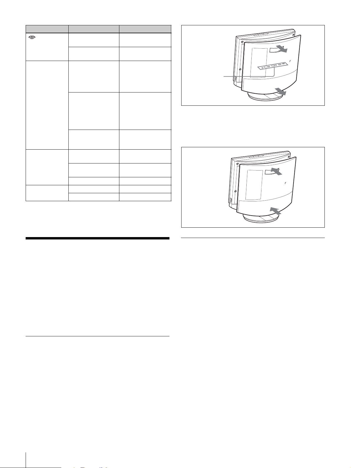
Indicatore Stato Significato
(“Memory
Stick”)
Lampada Tally Luce arancione Invio in corso
Link/Dati Luce verde Collegamento
100/10 Mbps Luce arancione 100 Mbps
Luce arancione
Spento Mancato accesso
Luce arancione
lampeggiante
(intervalli di 5
secondi)
Spento L’immagine della
Luce verde
lampeggiante
Spento Link offline
Spento 10 Mbps
Accesso alla
“Memory Stick”
alla “Memory Stick”
dell’immagine della
telecamera al
partecipante remoto
(coperchio obiettivo)
Invio in corso
dell’immagine della
telecamera al
partecipante remoto
(coperchio
dell’obiettivo chiuso)
telecamera non
viene inviata
stabilito
Trasferimento dati in
corso
Pannello dei
connettori (sotto
il coperchio
posteriore)
Per rimontare il coperchio posteriore
Spingere il coperchio all’interno mentre si allineano i
quattro mozzi.
* L’indicatore è acceso mentre il sistema viene avviato. Se viene rilevata una
temperatura anomala, l’indicatore lampeggia e il sistema si spegne.
Connessioni del sistema
In questa sezione vengono mostrati alcuni esempi
rappresentativi di collegamento del sistema.
Oltre a utilizzare l’apparecchio come unità indipendente, è
possibile collegare il PCS-TL30 a un computer da
utilizzare come schermo quando non c’è una
videoconferenza in corso. In questo caso è possibile
utilizzare due mouse diversi per il computer e per il PCSTL30, o collegare il PCS-TL30 e il computer con un cavo
USB generico e utilizzare lo stesso mouse per entrambi.
Informazioni sui connettori
I connettori del sistema si trovano sotto il coperchio
posteriore. Rimuovere il coperchio per effettuare i
collegamenti, quindi rimetterlo nella sua sede.
Precauzioni per il collegamento
Avvertimento
• Utilizzare esclusivamente l’adattatore CA e il cavo di
alimentazione forniti in dotazione.
• Quando si collega il cavo di alimentazione
dell’adattatore CA e il cavo CC, inserire le spine a fondo
accertandosi che abbiano fatto buona presa.
• Per motivi di sicurezza, non collegare il connettore
100BASE-TX/10BASE-T a una rete in cui possono
essere presenti tensioni eccessive.
Attenzione
• Prima di effettuare i collegamenti, accertarsi di avere
spento tutti i componenti.
• Per impedire che l’unità venga danneggiata, non
collegare o scollegare cavi mentre l’unità è accesa.
Per rimuovere il coperchio posteriore
Tirare il coperchio verso di sé per rimuoverlo.
86
Connessioni del sistema
Page 87
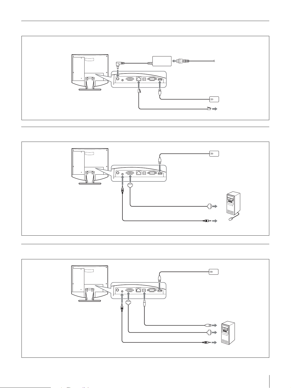
Esempio di collegamento (utilizzo come unità indipendente)
Effettuare i collegamenti nell’ordine 1 - 5.
3 A connettore
DC19,5V
Sistema di
comunicazione video
PCS-TL30
A porta 100BASE-TX/ 2
10BASE-T
Adattatore CA PCS-AC19V6A
o PCGA-AC19V7
(in dotazione)
1 A porta del mouse
Cavo UTP categoria 5 (cavo diritto, disponibile in commercio)
4 Cavo di alimentazione (in dotazione)
5 A uscita CA
(120 V CA)
Mouse ottico PCS-RMU1
(in dotazione)
A LAN
Esempio di collegamento per utilizzo con computer (mouse separato)
Mouse ottico PCS-RMU1
Sistema di
comunicazione video
PCS-TL30
A porta del mouse
(in dotazione)
A jack AUDIO IN
A connettore RGB IN
Cavo con connettore mini D-sub
a 15 piedini (disponibile in
commercio)
Cavo audio con mini plug stereo
(disponibile in commercio)
A uscita RGB
A uscita audio
Computer
Esempio di collegamento per utilizzo con computer (mouse in condivisione)
Mouse ottico PCS-RMU1
Sistema di
comunicazione video
PCS-TL30
A jack
AUDIO IN
A porta del mouse
A
connettore
RGB IN
A porta del PC
Cavo USB (available
separately) (disponibile
in commercio) *
A porta USB
(in dotazione)
* Non utilizzare un cavo USB di
lunghezza superiore a 3 m (9,84 piedi).
Cavo con connettore mini D-sub a 15
piedini (disponibile in commercio)
Cavo audio con mini plug stereo
(disponibile in commercio)
A uscita RGB
A uscita audio
Computer
Connessioni del sistema
87
Page 88
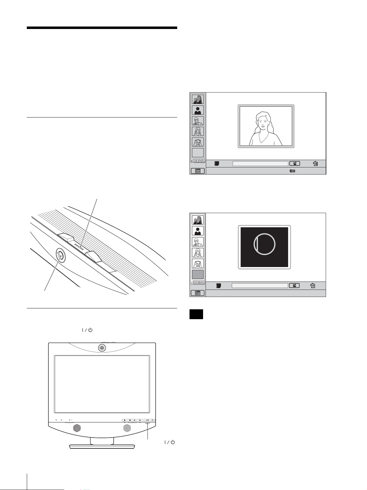
Inserimento e
disinserimento del sistema
L’indicatore dell’interruttore si accende emettendo una
luce arancione e il sistema di comunicazione video si
accende. Al termine dell’accensione, l’indicatore emette
una luce verde. Sullo schermo viene visualizzato il menu
di lancio e appare l’immagine della videocamera locale.
Prima di inserire il sistema, accertarsi che le connessioni
del sistema siano state effettuate correttamente.
Le schermate possono essere diverse da quelle mostrate
qui, a seconda del software.
Apertura del coperchio dell’obiettivo
Il sistema è dotato di un coperchio dell’obiettivo per
proteggere la videocamera. Prima di dare inizio a una
videoconferenza, togliere il coperchio dell’obiettivo
facendo scorrere la levetta del coperchio (nella parte
superiore del sistema) verso destra. Se il coperchio
dell’obiettivo è chiuso, l’immagine del sito locale non
verrà visualizzata sul sito remoto.
Levetta del coperchio dell’obiettivo
Menu di lancio
EMPTY
Fare clic sull’icona per attivare la funzione.
Quando il coperchio dell’obiettivo è chiuso, il menu di
lancio viene visualizzato nel modo riportato di seguito.
CLOSED
Number :012.345.678.912
Videocamera
Accensione del sistema
Premere l’interruttore (Alimentazione) sul PCS-TL30.
Closed
EMPTY
Fare clic sull’icona per attivare la funzione.
Note
Number :012.345.678.912
• La prima volta che si preme l’interruttore di
alimentazione dopo aver inserito il cavo di
alimentazione nella presa di corrente, possono
trascorrere anche dieci secondi prima che l’indicatore
dell’interruttore si accenda.
• Quando si accende il sistema di comunicazione video
per la prima volta dopo l’installazione, viene
visualizzata la procedura di impostazione guidata.
Impostare il sistema mediante la procedura guidata.
88
Inserimento e disinserimento del sistema
Interruttore
(Alimentazione)
Page 89
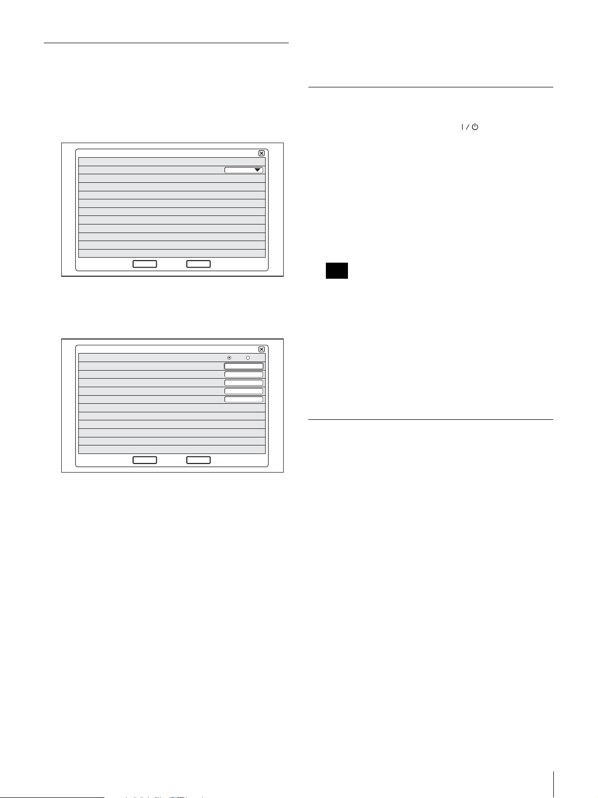
Installazione guidata
Alcune impostazioni posso variare leggermente in
funzione del software dello schermo.
1
Accedere all’elenco a discesa “Language” e scegliere
la lingua che verrà utilizzata per i menu e i messaggi.
4
Fare clic su “Salva”.
Le impostazioni vengono salvate.
Spegnimento del sistema
1
Premere due volte l’interruttore (Alimentazione).
Language
Next
2
Fare clic su “Next”.
3
Effettuare le opportune impostazioni LAN.
Modalità DHCP
Nome host
Indirizzo IP
Maschera di rete
Indirizzo Gateway
Indirizzo DNS
Cancel
English
Auto Off
1/2
Dopo aver premuto una volta l’interruttore, viene
visualizzato il messaggio “Per entrare nella modalità
standby, attendere alcuni secondi. Per spegnere il
sistema, premere nuovamente l’interruttore di
alimentazione.”. Premere nuovamente l’interruttore di
alimentazione.
2
Disinserire l’alimentazione delle altre apparecchiature
utilizzate per la videoconferenza.
Note
• Disinserire l’alimentazione del sistema se questo
non verrà utilizzato per un periodo prolungato. Con
l’alimentazione disinserita, non è possibile ricevere
una chiamata da un partecipante remoto.
• Quando si utilizza il sistema come schermo
2/2
computer nella modalità PC, è possibile spegnere il
sistema premendo una sola volta l’interruttore di
alimentazione.
• Durante una conferenza l’interruttore di
alimentazione è disattivato.
Impostazione del sistema di
Salva
Precedente
Modalità DHCP: imposta la modalità DHCP
(Dynamic Host Configuration Protocol).
Auto: assegna automaticamente l’indirizzo IP, la
maschera di rete, l’indirizzo gateway e
l’indirizzo DNS.
Off: disattiva DHCP. In questo caso occorre
assegnare manualmente l’indirizzo IP, la
maschera di rete, l’indirizzo gateway e
l’indirizzo DNS.
Nome host: inserire il nome host.
Indirizzo IP: inserire l’indirizzo IP.
Maschera di rete: inserire la maschera di rete.
Indirizzo Gateway: inserire l’indirizzo gateway
predefinito.
Indirizzo DNS: Inserire l’indirizzo del server DNS
(Domain Name System).
Se non si conoscono le impostazioni occorrenti per la
configurazione della LAN, contattare
l’amministratore di rete.
comunicazione video in modalità
standby
Quando si preme l’interruttore (Alimentazione) del PCSTL30, viene visualizzato il messaggio “Per entrare nella
modalità standby, attendere alcuni secondi. Per spegnere il
sistema, premere nuovamente l’interruttore di
alimentazione.”. Se ci si limita ad attendere, il sistema
entrerà nella modalità standby.
È possibile ricevere una chiamata da un partecipante
remoto nella modalità standby.
Per passare dalla modalità standby a quella normale,
premere una sola volta l’interruttore di alimentazione.
Inserimento e disinserimento del sistema
89
Page 90
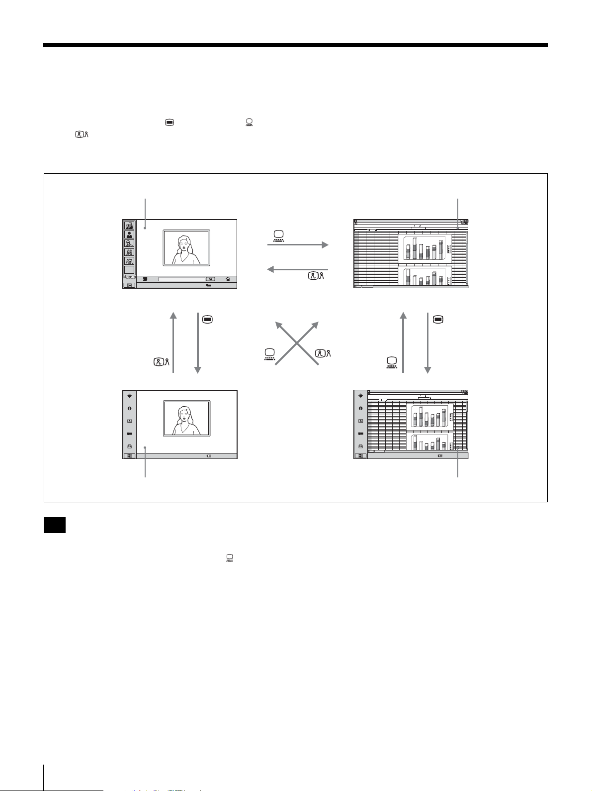
Commutazione tra schermo videoconferenza e
schermo computer
È possibile utilizzare il tasto (Menu), il tasto (PC) e
il tasto (Videoconferenza) nella parte inferiore
dell’unità per passare dallo schermo videoconferenza allo
schermo computer, e viceversa.
Schermo videoconferenza (menu di lancio) Schermo computer normale
ABCDEFGH IJ KLMN
1
abcd
2
EMPTY
Fare clic sull’icona per attivare la funzione.
Number :012.345.678.912
3
4
5
6
7
8
9
10
11
12
13
14
15
16
17
18
19
20
21
22
23
24
25
26
27
28
29
30
31
32
33
34
46
23
12
67
45
4
12
26
5
16
57
6
7
23
69
15
44
76
abcd
45
67
4
26
12
5
57
16
6
23
45
12
15
78
46
23
7
69
34
180
56
76
1
6
0
38
1
4
0
13
12
1
2
0
1
0
0
6
0
5
0
4
0
2
0
0
1
2
180
1
6
0
56
1
4
0
76
23
1
2
0
34
1
0
0
12
13
0
6
5
0
4
0
d
c
b
a
6
5
4
3
d
c
b
a
Fare clic sull’icona per attivare la funzione.
Number :012.345.678.912
Schermo videoconferenza (menu Impostazioni) Schermo computer (Menu Impostazioni)Schermo computer (Menu Impostazioni)
Note
• Quando il PCS-TL30 non è collegato a un computer, il
mouse vene disattivato premendo il tasto (PC) per
passare al Display computer.
• Se viene visualizzata un’immagine secondaria durante
una sessione di comunicazione, tale immagine rimarrà
visibile anche quando si commuta sul display computer.
Tuttavia il video riprodotto nell’immagine secondaria
proverrà dal sistema remoto o da quello locale.
• Quando si utilizzando dei mouse separati per il PCSTL30 e per il computer, il mouse attivo dipenderà dalla
schermata corrente. Quando viene visualizzato lo
schermo computer normale, è attivo il mouse collegato
al computer. Quando sono visualizzate altre schermate,
è attivo il mouse collegato al PCS-TL30.
ABCDEFGH IJ KLMN
1
2
abcd
3
12
46
23
34
4
4
5
5
6
6
7
69
8
44
9
10
11
12
13
14
15
16
17
18
19
20
21
22
23
24
25
abcd
26
4
27
5
28
6
29
12
30
46
31
69
32
33
34
Fare clic sull’icona per attivare la funzione.
180
67
45
56
12
26
76
1
6
0
16
57
38
4
0
1
7
23
13
76
15
12
2
0
1
0
1
0
6
0
5
0
0
4
0
2
0
1
2
180
6
0
1
67
45
56
4
0
1
12
26
76
16
57
23
2
0
1
45
23
34
0
0
1
78
15
12
7
23
13
6
0
5
0
4
0
3
5
4
d
c
b
a
6
d
c
b
a
Number :012.345.678.912
90
Commutazione tra schermo videoconferenza e schermo computer
Page 91
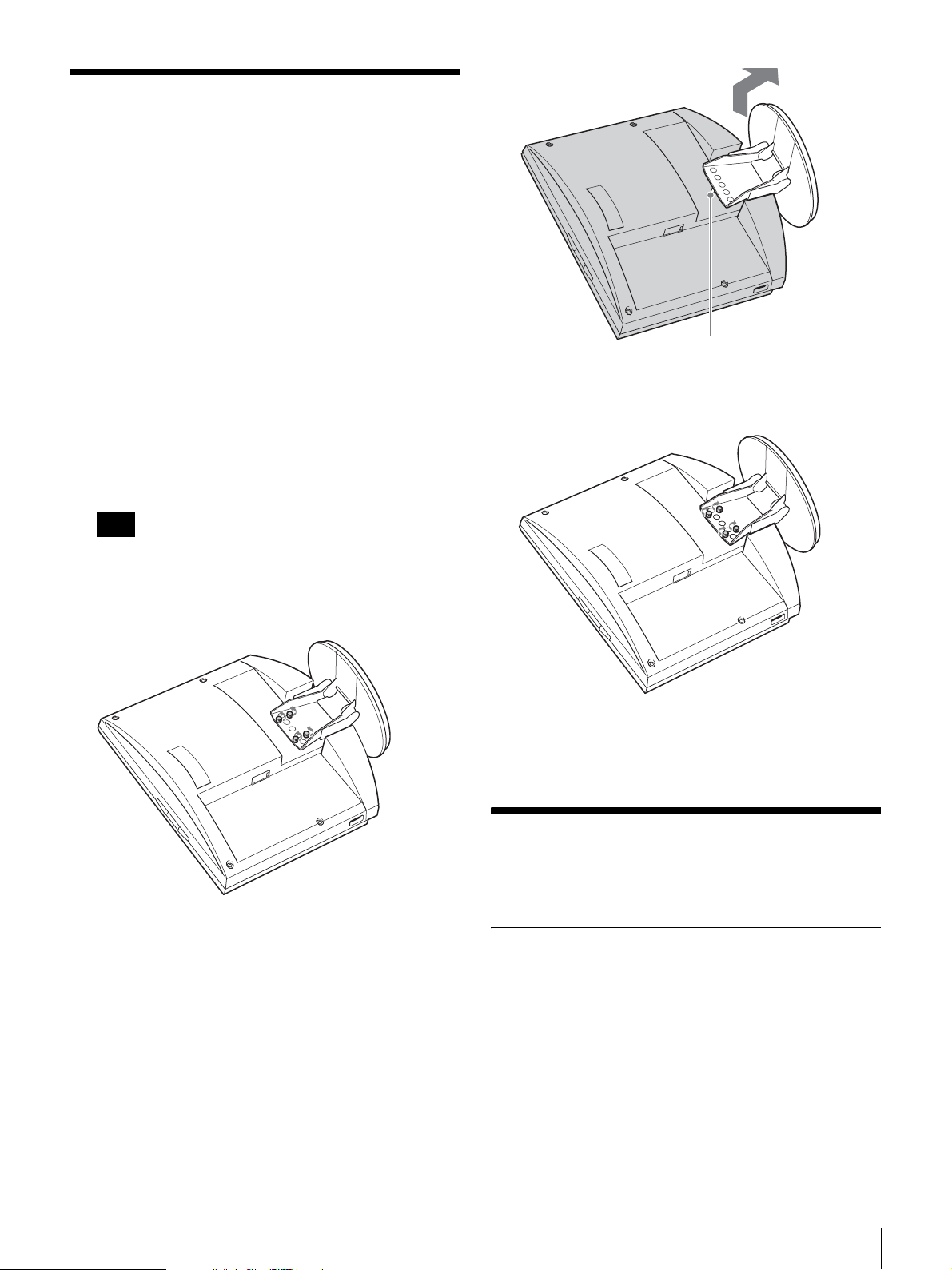
Regolazione dell’altezza
dello schermo
Il supporto e la sezione di visualizzazione del PCS-TL30
sono uniti mediante viti di fissaggio. Vi sono tre gruppi di
fori per viti, intervallati di 25 mm. Nelle condizioni
predefinite in fabbrica il display è fissato nella sua
posizione più bassa. Scegliendo un’altra serie di fori per
viti è possibile modificare l’altezza del display.
1
Rimuovere il coperchio posteriore dell’unità.
Per informazioni su come eseguire questa operazione,
vedere pagina 86.
2
Rimuovere le 4 viti usando una moneta o un oggetto
simile, sollevare il supporto e inserire la spina di
posizionamento nel foro in corrispondenza della
nuova posizione del supporto stesso.
Nota
Prima di modificare l’altezza dello schermo nel modo
suddetto, accertarsi di avere spento l’apparecchio.
Appoggiare il display a faccia in giù su un panno
morbido o un oggetto simile.
Spina di posizionamento
3
Avvitare le quattro 4 viti usando una moneta o un
oggetto simile per fissare il supporto.
4
Applicare nuovamente il coperchio posteriore.
Per ottenere le migliori
prestazioni
Luoghi in cui attivare o conservare il
sistema
Evitare di mettere in funzione o conservare il sistema nei
seguenti luoghi:
• luoghi estremamente caldi o freddi
• luoghi polverosi o soggetti a umidità
• luoghi esposti a forte vibrazione
• in prossimità di fonti di forti campi magnetici
• In prossimità di fonti di forti radiazioni
elettromagnetiche, come trasmettitori radio o TV
• luoghi con interferenze elevate
Regolazione dell’altezza dello schermo / Per ottenere le migliori prestazioni
91
Page 92

Schermo LCD
• Non esporre la superficie dello schermo LCD ai raggi
solari. I raggi solari potrebbero danneggiare la superficie
dello schermo.
• Non esercitare pressione o graffiare lo schermo LCD, o
posizionare oggetti sopra al sistema. L’immagine
potrebbe divenire irregolare oppure lo schermo LCD
potrebbe danneggiarsi.
• Se il sistema viene utilizzato in luoghi freddi, l’immagine
potrebbe risultare macchiata o diventare scura. Ciò non
indica la presenza di un guasto. Tali fenomeni tendono a
scomparire quando le temperature aumentano.
• Potrebbero comparire delle ombre quando i fermi
immagine vengono visualizzati in modo continuo. Tali
ombre scompariranno dopo alcuni istanti.
• Lo schermo e le parti esterne si riscaldano quando il
sistema è in uso. Non si tratta di un problema di
malfunzionamento.
Display LCD
Sebbene il display LCD si basi su una tecnologia ad alta
precisione, è possibile che compaiano dei punti neri o che
dei punti luminosi (rossi, blu o verdi) compaiano sullo
schermo LCD in modo costante. É anche possibile che
compaiano delle strisce colorate e zone a luminosità
irregolare quando si adottano angolazioni di
visualizzazione specifiche. Si tratta di una proprietà
strutturale del display LCD e non di un difetto di
funzionamento.
Altoparlanti incorporati
Gli altoparlanti sono fonti di campi magnetici. Per evitare
di danneggiare i dati, tenere i nastri e i dischi magnetici
lontano dagli altoparlanti.
Pulizia
• Prima della pulizia, scollegare il cavo di alimentazione
del PCS-TL30 dalla presa CA.
• La superficie dello schermo LCD ha una finitura di
rivestimento speciale. Per rimuovere la polvere dalla
superficie dello schermo, passare delicatamente un
panno morbido asciutto.
• Non utilizzare solventi quali alcol, benzene o diluenti,
perché tali prodotti potrebbero danneggiare o decolorare
il rivestimento della superficie.
• Quando si utilizzano panni di pulizia impregnati di
prodotti chimici, consultarne le istruzioni.
• Non applicare sostanze volatili (ad es.: insetticidi)
all’unità, o lasciare oggetti di gomma o di plastica a
contatto con essa per lunghi periodi, perché ciò può
danneggiare o decolorare la finitura superficiale.
Caratteristiche tecniche
PCS-TL30 Sistema di comunicazione video
La presente unità è conforme alle raccomandazioni ITUT H.323 e IETF SIP.
Immagini in movimento
Larghezza di banda di funzionamento
Da 64 kbps a 2048 kbps
Codifica H.261/H.263/H.263+/H.263++/H.264
(raccomandazione ITU-T)
MPEG4 Simple Profile
Elementi immagine
CIF: 352 pixel × 288 linee
QCIF: 176 pixel × 144 linee
Fermo immagine
Pixel 704 pixel × 576 linee
Codifica H.261 (raccomandazione ITU-T) Annex.
D (4CIF)
H.263 (formato speciale di questo
sistema)
Audio
Larghezza di banda
14 kHz (MPEG4 Audio)
7 kHz (G.722 conforme alle
raccomandazioni ITU-T)
3,4 kHz (G.711/G.728/G.729, conforme
alle raccomandazioni ITU-T)
Velocità di trasmissione
64 kbps, 96 kbps (MPEG4 Audio)
56 kbps, 64 kbps (G.711, conforme alle
raccomandazioni ITU-T)
48 kbps, 56 kbps, 64 kbps (G.722,
conforme alle raccomandazioni ITUT)
16 kbps (G.728, conforme alle
raccomandazioni ITU-T)
8 kbps (G.729, conforme alle
raccomandazioni ITU-T)
Rete
Trasmissione in multiplex
Video, audio, dati
Formato fotogramma
H.225.0 (conforme alle raccomandazioni
ITU-T)
Interfaccia LAN (100BASE-TX/10BASE-T)
Protocollo LAN supportato
HTTP
FTP
Telnet
RTP/RTCP
TCP/UDP
IP
92
Caratteristiche tecniche
Page 93

Controllo a distanza
Controllo videocamera remota
H.281 (conforme alle raccomandazioni
ITU-T)
Telecamera
Dispositivo immagine
1/3,2 pollici a colori CMOS (pixel
efficaci totali: 1,3 milioni circa)
Obiettivo f = 2,3 mm
F = 1:2,8
Angolazione orizzontale: circa 88°
Angolazione verticale: circa 73°
Distanza focale 300 mm
Funzione Panoramica/inclinazione/zoom
Mediante elaborazione digitale
Funzione Bilanciamento del bianco incorporata
Velocità di trasmissione dei fotogrammi
30/15 fps, con commutazione automatica
in base all’intensità della luce
ambiente
Schermo
Grandezza Tipo 17,1 ampio
Risoluzione 1280 × 768 (WXGA)
Tempo di risposta
13 ms o meno
Rapporto di contrasto
600 : 1
Angolo di visione
176 gradi o oltre
Numero di colori
16.700.000 colori
Controllo immagine
PinP 4 angoli
PandP Tre finestre
Ingresso Interno: comunicazione video
RGB esterno: display computer
Modalità Ampio
Normale, Zoom, Ampio
Modalità RGB 640 × 480, 800 × 600, 1024 × 768,
1280 × 768, ecc.
La visualizzazione di immagini
ingrandite è possibile.
Altoparlante
Altoparlante 3 W × 2
Microfono
Campo di frequenza
14 kHz
Caratteristiche direzionali
Direzionale ad angolo diretto
Dati generali
Alimentazione
19,5 V
Consumo di corrente
6,15 A
Temperatura di utilizzo
Da 5°C a 35°C (da 41°F a 94°F)
Umidità durante l’esercizio
da 20% a 80%
Temperatura di immagazzinamento
Da -20°C a +60°C (da –4°F a +140°F)
Umidità di immagazzinamento
da 20% a 80% (senza condensa)
Dimensioni 424 × 376 × 95,5 mm (l/a/p)
3
(16
/4 × 14 7/8 × 3 7/8 pollici)
(supporto escluso)
424 × 419 × 258 mm (l/a/p)
3
(16
/4 × 16 1/2 × 10 1/4 pollici)
(supporto incluso)
Peso Circa 8 kg (17 lb 9 oz)
Accessori in dotazione
Mouse ottico PCS-RMU1 (1)
Adattatore CA PCS-AC19V6A/PCGA-
AC19V7 (1)
Cavo di alimentazione (1)
CD-ROM (1)
Guida introduttiva (1)
Garanzia (1)
Adattatore CA PCS-AC19V6A o PCGAAC19V7
Alimentazione
100 - 240 V CA, 50/60 Hz, 1,8 A
Uscita 19,5 V, 6,15A
Temperatura di utilizzo
Da 5°C a 35°C (da 41°F a 94°F)
Umidità durante l’esercizio
da 20% a 80%
Temperatura di immagazzinamento
Da -20°C a +60°C (da –4°F a +140°F)
Umidità di immagazzinamento
da 20% a 80% (senza condensa)
Dimensioni 80 × 40 × 160 mm (l/a/p) (3
3
6
/8 pollici)
1
/4 × 1 5/8 ×
Peso Circa 800 g (1 lb 12 oz)
Microfono PCS-A1 (opzionale)
Larghezza di banda
13 kHz
Caratteristiche direzionali
Omnidirezionale
Dimensioni 74 × 16 × 93 mm (l/a/p)
Peso Circa 170 g (6 oz)
Alimentazione Alimentazione mediante presa
21
(3 ×
/32 × 3 3/4 pollici)
Caratteristiche tecniche
93
Page 94
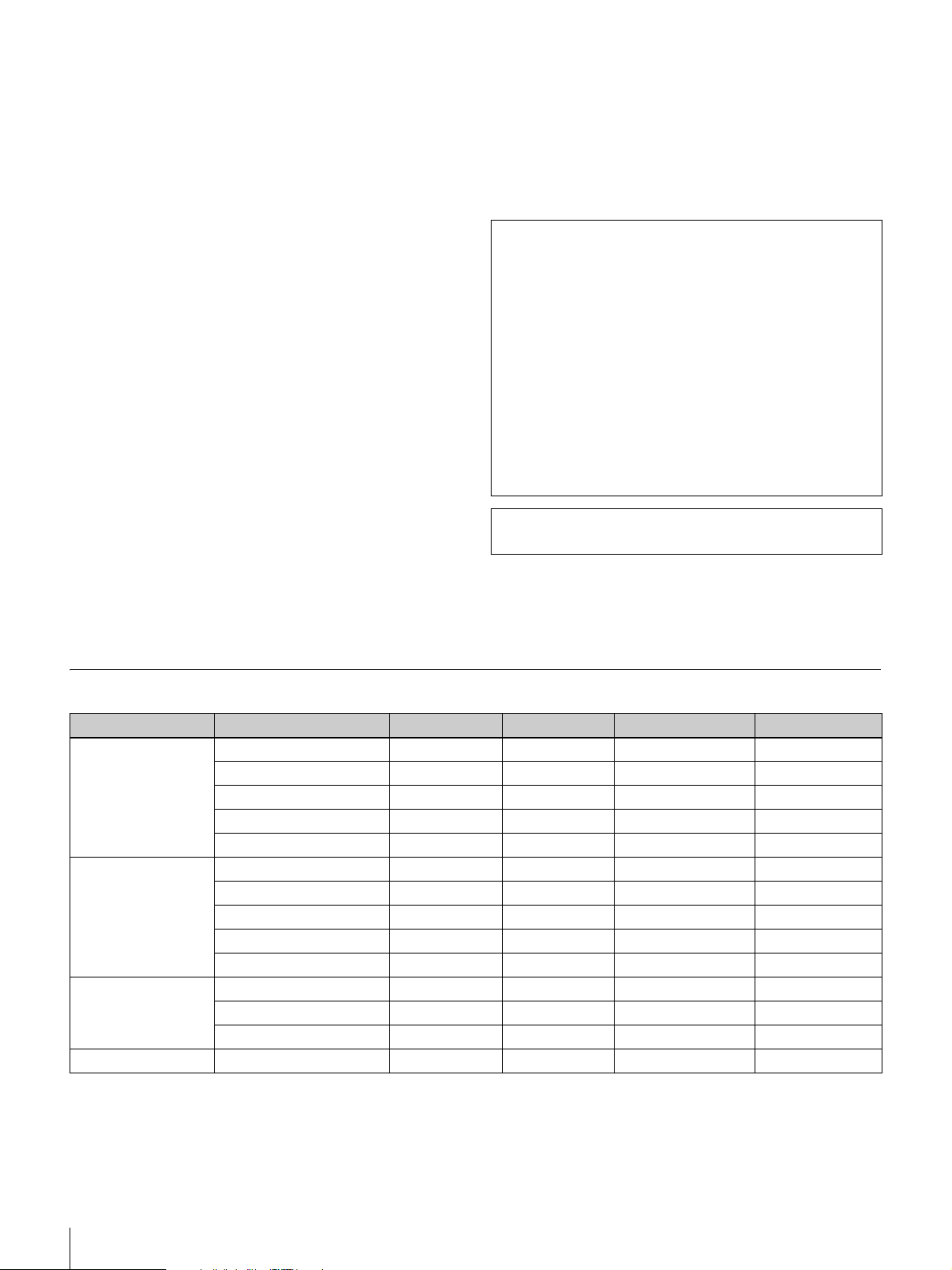
Microfono PCSA-A3 (opzionale)
Larghezza di banda
13 kHz
Caratteristiche direzionali
Unidirezionale
Dimensioni 68 × 16 × 96 mm (l/a/p)
3
(2
/4 × 21/32 × 3 7/8 pollici)
Peso Circa 200 g (7 oz)
Alimentazione Alimentazione mediante presa
Data Solution Module PCSA-DSM1
(opzionale)
Consumo di corrente
20 W max.
Temperatura di utilizzo
da 5°C a 35°C (da 41°F a 94°F)
Umidità durante l’esercizio
da 20% a 80%
Temperatura di immagazzinamento
da -20°C a +60°C (da –4°F a +140°F)
Umidità di immagazzinamento
da 20% a 80% (senza condensa)
Dimensioni 107 × 250 × 34 mm (l/a/p)
Peso Circa 550 g (1 lb 3 oz)
Accessori in dotazione
1
(4
/4 × 9 7/8 × 1 3/8 pollici) (escluse le
parti sporgenti)
Guida introduttiva (1)
Garanzia (1)
Software SIP PCSA-SP1 (opzionale)
Accessori in dotazione
Sigillo numero di serie (1)
Istruzioni per l’uso (1)
Design e caratteristiche tecniche sono soggetti a modifiche
senza preavviso.
Il cancellatore d’eco dell’unità è stato sviluppato con una
licenza concessa da Nippon Telegraph and Telephone
Corporation. Inoltre Nippon Telegraph and Telephone
Corporation detiene il copyright del software di
cancellazione dell’eco.
Non è consentito utilizzare o vendere le tecnologie
adoperate nell’unità, né integralmente né parzialmente,
per armi o per la fabbricazione di armi. Tutti i diritti
relativi al software incorporato nell’unità e le copie della
relativa documentazione sono di proprietà di Nippon
Telegraph and Telephone Corporation e di Sony. Non è
cosentito copiare, sottoporre a reverse engineering,
decompilare, disassemblare o modificare le tecnologie
incorporate nell’unità.
Questo prodotto utilizza font bitmap Ricoh, prodotte e
commercializzate da Ricoh Co., Ltd.
Dati tecnici ingresso/uscita RGB
Elementi immagine Formato del segnale fH (kHz) fV (Hz) Dot clock (MHz) Sync
640 × 480 Modo VGA 31,469 59,94 25,17 H-neg V-neg
Macintosh 13" 35 66,667 30,24 H-neg V-neg
VGA VESA 72 Hz 37,861 72,809 31,5 H-neg V-neg
VGA VESA 75 Hz 37,5 75 31,5 H-neg V-neg
VGA VESA 85 Hz 43,269 85,008 36 H-neg V-neg
800 × 600 SVGA VESA 56 Hz 35,156 56,25 36 H-pos V-pos
SVGA VESA 60 Hz 37,879 60,317 40 H-pos V-pos
SVGA VESA 72 Hz 48,077 72,188 50 H-pos V-pos
SVGA VESA 75 Hz 46,875 75 49,5 H-pos V-pos
SVGA VESA 85 Hz 53,674 85,061 56,25 H-pos V-pos
1024 × 768 XGA VESA 60 Hz 48,363 60,004 65 H-neg V-neg
XGA VESA 70 Hz 56,476 70,069 75 H-neg V-neg
XGA VESA 75 Hz 60,023 75,029 78,75 H-pos V-pos
1280 × 768 WXGA VESA 60 Hz* 47,693 59,992 80,12 H-neg V-pos
* Non può essere trasmesso tramite il Data Solution Module PCSA-DSM1.
94
Caratteristiche tecniche
Page 95

中文
警告
为减少火灾或电击的危险,请勿使本产品淋雨
或受潮。
为避免电击,请勿拆卸机壳。维修事宜应仅由
合格维修人员进行。
警告
请使用本设备附带的交流电源适配器作为电源。
随机附带下列交流电源适配器:
制造厂商 型号
Sony PCS-AC19V6A
Sony PCGA-AC19V7
使用任何其他电源可能会导致火灾之类的危险。
本设备的断开装置为交流电源适配器的电源插头。
必须使用本设备的电源插头断开电源。
请确保电源插座安装在本设备附近且便于使用。
如果电源适配器工作异常,应断开电源插头。
注意
请使用经各国 (使用本设备的国家)专门检测机构
许可的电源线组件。
LAN 端口注意事项
为了安全起见,请不要将 LAN 端口连接到任何有过
电压的网络设备。
对于欧洲用户
警告
此为 A 类产品。当在居住环境中使用时,此产品可
能会产生电磁干扰。在此情况下,用户会被要求采取
某些适当的对策。
在有干扰存在的情况下,请联系离您最近的 Sony 维
修机构。
CS
95
Page 96

目录
提供的文档 ........................... 97
功能 ................................. 97
集成的便携式视频通信系统 ......... 97
直观的用户界面 ................... 97
当作计算机显示器使用 ............. 97
检查包装内容 ......................... 98
部件的名称与功能 ..................... 98
指示灯名称和功能 ................ 100
系统连接 ............................ 100
关于连接器 ...................... 100
连接注意事项 .................... 101
连接范例 (单独使用) ............ 102
随同计算机使用的连接范例
(独立鼠标)................. 102
随同计算机使用的连接范例
(共享鼠标)................. 102
打开 / 关闭系统 ...................... 103
打开镜头盖 ...................... 103
打开系统 ........................ 103
初始设置向导 .................... 104
关闭系统 ........................ 104
将视频通信系统设置为待机模式 .... 104
在视频会议显示器和计算机显示器之间进行切
换 .............................. 105
调节显示器的高度 .................... 106
要想达到最佳性能 .................... 106
操作和存储位置 .................. 106
液晶显示屏 ...................... 106
液晶显示屏 ...................... 107
内置扬声器 ...................... 107
清洁 ............................ 107
规格 ................................ 107
RGB 输入 / 输出规格 ............... 109
本 “快速入门指南”提供了重要的预防措施和产品
操作说明,以防意外事故或伤害。 为确保产品的安
全操作,请认真阅读本指南并保留以供将来参考。
同时,要想了解本产品更为详细的信息,请参阅存
储在所提供的 CD-ROM 中的操作说明。 您可以同时参
考本文档与 “快速入门指南”。
96
目录
Page 97
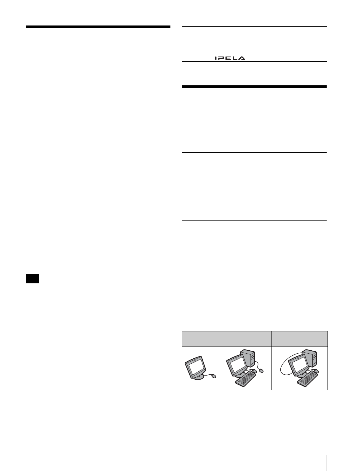
提供的文档
随本产品提供了一些文档,列表如下。 根据您的实际
需要,查阅相应的文档。
快速入门指南 (本文档)
提供了有关初始设置和如何连接系统的基本信息。
(附送的 CD-ROM 也包含相同的 “快速入门指南”文
件。)
操作说明 (存储在附送的 CD-ROM 中)
针对实施不同种类视频会议会话所必需的操作程序和
设置,提供了详细的信息。 本文档包括了该产品的所
有功能。
CD-ROM 操作要求
使用 CD-ROM 需要下列的系统要求。
• 计算机: 配备 Intel
- 内存: 64 MB 或更大
- 光驱: 8 倍速或更快
• 显示器: 分辨率 800 × 600 或更高
• 操作系统: Microsoft
或 Windows XP Home Edition
如果达不到上述要求,CD-ROM 的运行速度就会变慢
或不可用。
®
Pentium®处理器
®
Windows® XP Professional
• Adobe 和 Adobe Reader 是 Adobe Systems Incorporated 的商标。
• Microsoft和Windows是Microsoft Corporation在美国和其它国家
的注册商标。
• Intel和Pentium 是Intel Corporation或其分公司在美国和其它国
家的商标或注册商标。
• “IPELA”和 是 Sony Corporation 的商标。
功能
PCS-TL30 视频通信系统是一个视频会议系统,通过
使用网络传输和接收图像及声音,可以与对方进行自
然的、面对面的交流。 另一方可以位于任何地点,包
括国外。
集成的便携式视频通信系统
视频通信系统所需的全部元件,包括摄像机、监视
器、编码解码器、麦克风和扬声器等,都集成在一个
小巧的机壳内。 这确保了系统的便携性,几乎可以让
您在任何地点进行视频会议。
内置的 17 寸监视器支持宽屏模式,内置的摄像机配
备数码全景 / 倾斜和变焦功能。
准备
想要访问附送的 CD-ROM 中的操作说明,计算机上最
少要安装有下列软件应用程序中的一种:
• Adobe
• Adobe Reader 6.0 或更新的版本
注意
如果没有安装 Adobe Reader,可以从下面的 URL 地址
进行下载:
http://www.adobe.com
®
Acrobat® Reader 4.0 或更新的版本
查看操作说明
1
将附送的 CD-ROM (标有 “Manuals for Video
Communication System”)插入计算机的光驱中。
稍后,屏幕上会出现 CD-ROM 内容列表。
2
双击文件名为 “中文”的 PDF。
Adobe Reader 开始运行,然后在屏幕上会显示
“视频通信系统”的 “操作说明”的第一页。
通过单击 “目录”区域的一个条目,可以直接跳
到相应的页面。
直观的用户界面
用户界面采用叠加设计,通过此设计,您只需使用附
送的鼠标单击即可控制操作。用户指南采用 “消息”
的形式,同时提供联机帮助。
当作计算机显示器使用
除了以独立模式操作之外,还可以将 PCS-TL30 连接
到计算机。 在这种情况下,既可以使用两个鼠标来操
作计算机和 PCS-TL30,也可以只用一个鼠标。
可单独使用的数据解决方案模块 PCSA-DSM1,能让您
在视频会议期间将计算机显示器上的屏幕内容传输给
对方。
单独使用 随同计算机和独立的
定位设备使用
随同计算机和一个定
位设备使用
提供的文档 / 功能
97
Page 98
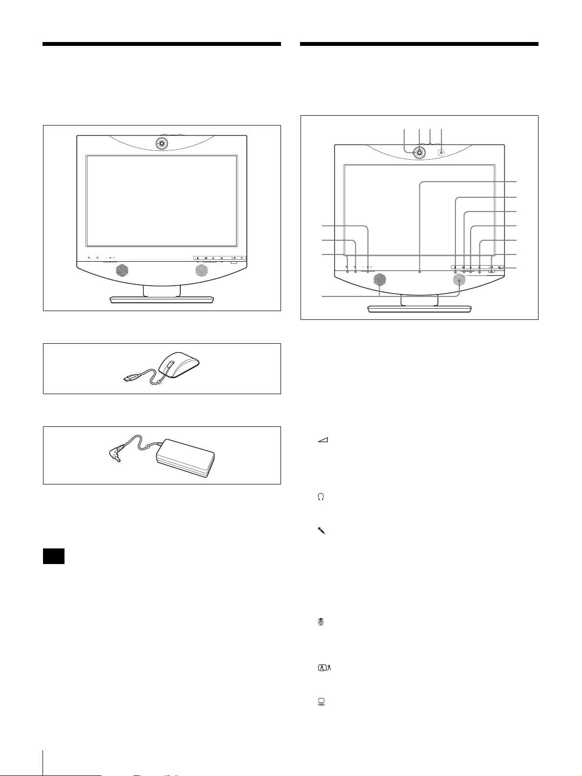
检查包装内容
1 423
部件的名称与功能
当打开此设备包装时,请确保出现下列所有的项目:
• PCS-TL30 主设备 (1)
• 光电鼠标 PCS-RMU1 (1)
正视图
5
6
7
8
a 信号灯
当发送本地视频到远程系统时,信号灯亮起。
b 摄像机镜头
9
q;
qa
qs
qd
qf
qg
• 交流电适配器 PCS-AC19V6A 或 PCGA-AC19V7 (1)
• 电源线 (1)
• 快速入门指南 (本文档)(1)
• CD-ROM (操作说明)(1)
• 保修单 (1)
注意
附送的 CD-ROM 包含的操作说明提供了有关操作程序
和全部设置的详细信息。这些文档以 PDF 格式文件提
供。
c 摄像机镜头盖控制杆
d 麦克风
e (音量)按钮
用来调节音量。
+: 提高音量。
-: 降低音量。
f (电话)插孔 (立体声微型插孔)
可连接一对耳机 ( 可购买得到 )。
g (麦克风)插孔 (微型插孔)
允许连接可选麦克风 PCS-A1 或 PCSA-A3。
h 扬声器
i 联机灯
主要显示传入 / 传出呼叫状态。
j 麦克风关闭按钮和指示灯
允许消除来自本地系统的声音。 再次按此按钮恢复向
远程系统发送声音。
k (视频会议)按钮和指示灯
用来从计算机屏幕切换到视频会议屏幕。
98
检查包装内容 / 部件的名称与功能
l (PC)按钮和指示灯
用来切换到计算机屏幕。
Page 99
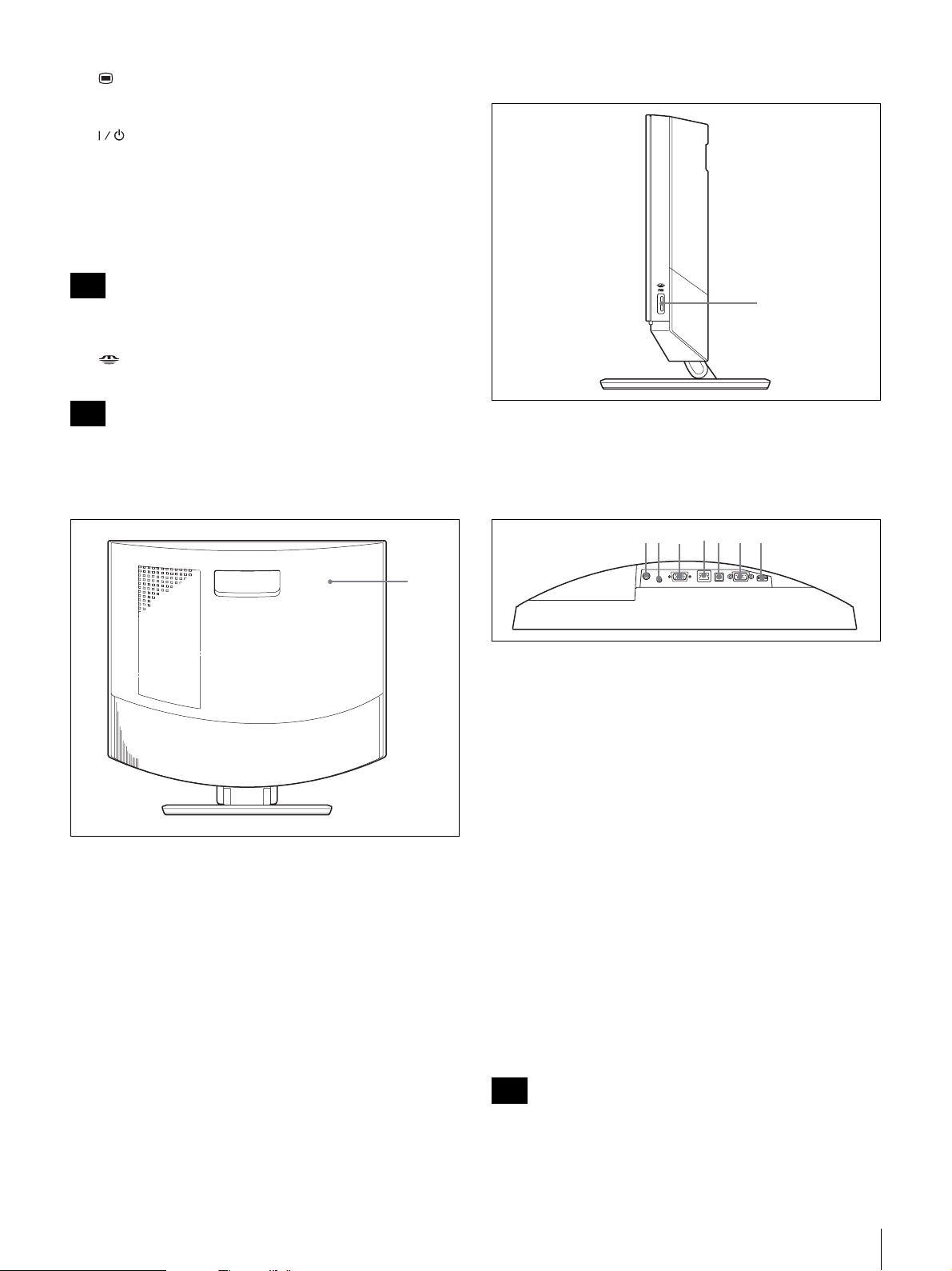
m (菜单)按钮
7653421
按此按钮显示 “安装”菜单。
n (电源)开关和指示灯
打开 / 关闭系统电源。
当在 PC 模式下使用系统作为计算机屏幕时,请按此
开关一次,关闭电源。
当在 VC 模式下使用系统时,请按此开关一次,将系
统设置为待机模式。想要在 VC 模式下关闭电源,请
在 5 秒之内按此开关两次。
右视图
注意
电源开关在通信会话期间不起作用。
o “记忆棒”指示灯
显示 “记忆棒”插槽的状态。
注意
此指示灯亮起时,不要移除 “记忆棒”。
后视图
1
1
a “记忆棒”插槽
可将 “记忆棒”插入此处。
连接器面板 (从下方看,位于后盖后方的部位)
a 19.5V 直流电连接器
将附送的交流电适配器 PCS-AC19V6A 或 PCGA-AC19V7
连接到此处。
b
AUDIO IN (PC 声音输入)插孔 (立体声微型插孔)
用 RGB IN 连接器将此插孔连接到计算机的音频输出
插孔。
a 后盖
移除此盖可以进入连接器面板。 底座和显示器的连接
部分也是位于面板的后方。 通过改变螺钉位置可以调
节显示器的高度。
c RGB IN 连接器 (15 针微型 D 型子连接器)
此处连接计算机的 RGB 输出插孔。
d 100BASE-TX/10BASE-T 端口 (RJ-45)
使用 Category 5 LAN 电缆将此端口连接到集线器或
类似设备。
此端口配备了链接 / 数据指示灯 (绿色)和 100/
10 Mbps 指示灯 (橙色)。
e PC 端口
当 PCS-TL30 和连接 RGB IN 连接器的计算机用同一个
鼠标时,使用此连接器。 将此连接器链接到计算机的
USB 端口。
注意
不要使用长度超过 3 米 (9.84 英尺 ) 的 USB 电缆。
部件的名称与功能
99
Page 100
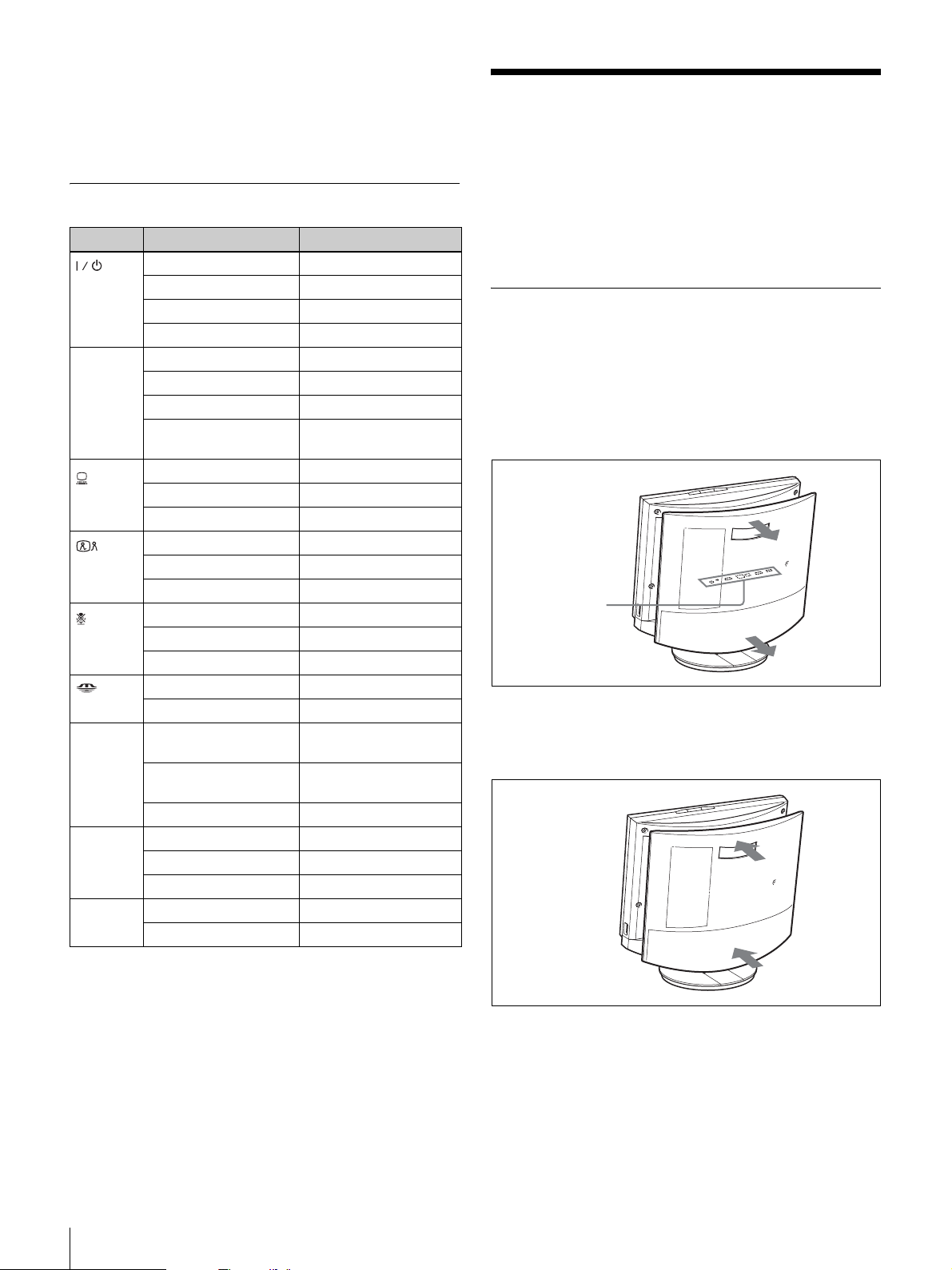
f RS-232C 端口 (9 针 D 型子连接器)
此连接器只为系统提供服务。
g 鼠标端口
将附送的光电鼠标 PCS-RMU1 连接到此处。
指示灯名称和功能
指示灯 状态 意义
绿灯亮起 电源开
*
(PC)
*
*
(“记
*
橙灯亮起 待机
橙灯闪烁 (1 秒循环) 风扇故障
熄灭 电源关
蓝灯闪烁 (3 次 / 秒) 发送 / 接收
蓝色照明灯亮起 通信正在进行中
蓝灯间歇闪烁 呼叫指示失败
熄灭 脱机 (非呼叫失败)或
待机
*
蓝灯亮起 计算机显示器
白灯亮起 视频会议显示器
熄灭 待机
蓝灯亮起 视频会议显示器
白灯亮起 计算机显示器
熄灭 待机
橙灯亮起 麦克风关
白灯亮起 麦克风开
熄灭 待机
橙灯亮起
熄灭 没有访问 “记忆棒”
橙灯闪烁 (5 秒循环) 将保密图像传送给对方
熄灭 没有发送摄像机图像
绿灯亮起 已建立链接
绿灯闪烁 正在传送数据
熄灭 链接已脱机
橙灯亮起 100 Mbps
熄灭 10 Mbps
访问 “记忆棒”
方 (镜头盖开)
(镜头盖关)
(电源)
联机
(视频会
议)
(麦克风
关)
忆棒”)
信号灯 橙灯亮起 将摄像机图像传送给对
链接 /
数据
100/
10 Mbps
系统连接
此部分显示了一些典型的系统连接范例。
除了以独立模式操作之外,还可以在没有进行视频会
议时,将 PCS-TL30 连接到计算机当作显示器使用。
在这种情况下,既可以使用两个鼠标来操作计算机和
PCS-TL30,也可以用通用 USB 电缆将 PCS-TL30 和计
算机连接到一起,然后只使用一个鼠标。
关于连接器
系统连接器位于后盖的下方。 取下后盖进行连接后,
再将后盖装回原位。
取下后盖
朝您的方向拉动并取下后盖。
连接器面板
(位于后盖下面)
装上后盖
对齐四个柱脚后将后盖推入。
* 系统启动时,指示灯亮起。如果发现温度异常,指示灯会闪烁,随
后电源关闭。
100
系统连接
 Loading...