

Page 1

3-859-501-12(1)
Rollabout P ac kage
Operating Instructions
Before operating the unit, please read this manual
thoroughly and retain it for future reference.
PCS-3000
PCS-3000P
1997 by Sony Corporation
-3000
Page 2
Owner’s Record
4.This equipment cannot be used on public coin phone
service provided by the telephone company. Connection
to party line service is subject to state tariffs.
The model and the serial numbers are located at the rear.
Record the serial number in the space provided below.
Refer to these numbers whenever you call upon your Sony
dealer regarding this product.
Model No. PCS-3000/3000P Serial No. ______________
WARNING
To prevent fire or shock hazard, do not
expose the unit to rain or moisture.
To avoid electrical shock, do not open the
cabinet. Refer servicing to qualified
personnel only.
For the customers in the USA
This device complies with Part 15 of the FCC Rules.
Operation is subject to the following two conditions: (1) This
device may not cause harmful interference, and (2) this
device must accept any interference received, including
interference that may cause undesired operation.
This equipment has been tested and found to comply with
the limits for a Class A digital device, pursuant to Part 15 of
the FCC Rules. These limits are designed to provide
reasonable protection against harmful interference when
the equipment is operated in a commercial environment.
This equipment generates, uses and can radiate radio
frequency energy and, if not installed and used in
accordance with the instruction manual, may cause harmful
interference to radio communications. Operation of this
equipment in a residential area is likely to cause harmful
interference in which case the user will be required to
correct the interference at his own expense.
You are cautioned that any changes or modifications not
expressly approved in this manual could void your authority
to operate this equipment.
The shielded interface cable recommended in this manual
must be used with this equipment in order to comply with
the limits for a computing device pursuant to Subpart B of
Part 15 of FCC Rules.
IMPORTANT INSTRUCTION TO USERS
1.If this terminal equipment causes harm to the telephone
network, the telephone company will notify you in
advance that temporary discontinuance of service may be
required. But if advance notice is not practical, the
telephone company will notify the customer as soon as
possible.
2.The telephone company may make changes in its
facilities, equipment, operations or procedures that could
affect the operation of the equipment. If this happens the
telephone company will provide advance notice in order
for you to make necessary modifications to maintain
uninterrupted service.
3.If trouble is experienced with this equipment for repair or
warranty information, please contact Sony Business
Information Center S 1-800-686-7669. If the equipment
is causing harm to the telephone network, the telephone
company may request that you disconnect this equipment
until the problem is resolved.
2
For the Customers in the United Kingdom
APPROVAL NOTICE
Rollabout processor PCS-P300P is approved for connection
to PSTN using basic rate access interface compatible with
CCITT I.420 (ISDN).
The BABT approval number for PCS-P300P is
BABT/606970.
This manual focuses on using ISDN lines to conduct
a videoconference, but it also covers non-ISDN
lines. If you use ISDN lines, consult your Sony
dealer for more information.
• The ISDN service may not be available in some
areas.
Voor de klanten in Nederland
Bij dit produkt zijn batterijen geleverd.
Wanneer deze leeg zijn, moet u ze niet
weggooien maar inleveren als KCA.
For the customers in Canada
This Class A digital apparatus complies with Canadian
ICES-003.
NOTICE: The Industry Canada label identifies certified
equipment. This certification means that the equipment
meets certain telecommunications network protective,
operational and safety requirements as prescribed in the
appropriate Terminal Equipment Technical Requirements
document (s). The Department does not guarantee the
equipment will operate to the user’s satisfaction.
Before installing this equipment, users should ensure that it
is permissible to be connected to the facilities of the local
telecommunications company. The equipment must also be
installed using an acceptable method of connection. The
customer should be aware that compliance with the above
conditions may not prevent degradation of service in some
situations.
Repairs to certified equipment should be made by an
authorized Canadian maintenance facility designated by the
supplier. Any repairs or alterations made by the user to this
equipment, or equipment malfunctions, may give the
telecommunications company cause to request the user to
disconnect the equipment.
Users should ensure for their own protection that the
electrical ground connections of the power utility, telephone
lines and internal metallic water pipe system, if present, are
connected together. This precaution may be particularly
important in rural areas.
Caution: Users should not attempt to make such
connections themselves, but should contact the appropriate
electric inspection authority, or electrician, as appropriate.
Page 3
Table of Contents
Precautions.................................................................................................5
On Safety..............................................................................................5
On Handling .........................................................................................5
When You Discard Camera Unit..........................................................6
Features ......................................................................................................7
Chapter 1
Using the Basic System
Quick operation
For a quick understanding on the
basic operation of the Rollabout
Package, read Chapter 1.
Chapter 2
Settings
Using the Remote Commander ............................................................ 1-1
Basic System Connections..................................................................... 1-2
Menus...................................................................................................... 1-4
Switching Menus.............................................................................. 1-5
Basic Adjustments ................................................................................. 1-9
Adjusting the Volume ...................................................................... 1-9
Selecting the Picture....................................................................... 1-10
Monitoring Yourself in the Inset Window ..................................... 1-11
Adjusting Local and Remote Cameras........................................... 1-12
Presetting Angle, Zoom And Camera Brightness .......................... 1-14
Tracking a Subject Automatically — AT (Automatic Target
Tracking) Function............................................................... 1-15
About Backup................................................................................. 1-16
Muting Local Conversations (Mute Function)............................... 1-17
Checking Connection Status............................................................... 1-18
Holding a Meeting With Multiple Remote Parties ........................... 1-19
Preparing for a Multi Meeting........................................................ 1-19
Connecting with Other Parties ....................................................... 1-20
Changing the Picture Display Format ............................................ 1-24
Using Two ISDN Lines.................................................................. 1-24
Ending the Multi Meeting .............................................................. 1-26
Connecting With MCU to Perform the Chairman Control ............ 1-26
Registering a Remote Party .................................................................. 2-1
Making an Entry............................................................................... 2-1
Modifying an Entry .......................................................................... 2-7
Deleting an Entry.............................................................................. 2-8
Setting the Answer Mode ...................................................................... 2-9
Synchronizing Voice and Motion (Lip Synchronization) ................ 2-11
Registering Sub Addresses and Local System Data ......................... 2-13
SPID Registration for Customers in the USA................................... 2-15
Setting the Clock.................................................................................. 2-20
Adjusting the Camera Brightness ...................................................... 2-22
Shooting With Backlighting........................................................... 2-22
Adjusting the Brightness ................................................................ 2-23
Setting the Initial Volume Level on the TV Monitor ....................... 2-24
SETUP Menu ....................................................................................... 2-25
Displaying the SETUP Menu ......................................................... 2-25
SETUP Menu Items........................................................................ 2-26
Chapter 3
Conducting a Meeting
Turning the System On/Off .................................................................. 3-1
Turning On ....................................................................................... 3-1
Turning Off....................................................................................... 3-2
Switching On for the First Time....................................................... 3-3
Starting a Meeting ................................................................................. 3-4
Calling a Remote Party..................................................................... 3-4
Receiving a Call ............................................................................... 3-8
Ending a Meeting................................................................................. 3-11
Table of contents 3
Page 4

Table of contents
Chapter 4
Operation of Optional
Items
Options.................................................................................................... 4-1
Sending Images from the Video Presentation Stand.......................... 4-3
Connecting the Video Presentation Stand ........................................ 4-3
Sending a Still Picture from the Video Presentation Stand.............. 4-3
Sending Moving Picture As Still Pictures Continuously ................. 4-5
Controlling Zoom With the Menu.................................................... 4-6
Sending Video Images and Sound to a Remote Party........................ 4-7
Connecting Video Equipment .......................................................... 4-7
Sending Video Image and Sound From a VCR ............................... 4-8
Recording a Meeting ........................................................................... 4-10
Connecting a VCR.......................................................................... 4-10
Recording ....................................................................................... 4-10
Installing Optional Interface Boards ................................................. 4-11
Using the V.35 Interface...................................................................... 4-12
Using Two ISDN Lines........................................................................ 4-13
Using Multiple Microphones .............................................................. 4-14
Connecting Second Microphone .................................................... 4-14
Connecting the Multiple Microphones via the Audio Mixer ......... 4-15
Connecting the Speakers to the Monitor........................................... 4-16
Preparing for a Data Conference ....................................................... 4-17
Installing FarSite ............................................................................ 4-17
Setting Up FarSite .......................................................................... 4-17
Connecting with a Computer ............................................................. 4-20
Using FarSite........................................................................................ 4-21
Using NetMeeting ................................................................................ 4-24
Setting Up NetMeeting................................................................... 4-24
Connecting With NetMeeting ........................................................ 4-25
Sending the Dial Tone to the Remote Party ...................................... 4-26
Appendix
Location and Function of Parts and Controls ................................... A-1
Rollabout Processor......................................................................... A-1
Camera Unit .................................................................................... A-4
Remote Commander........................................................................ A-5
Inserting Batteries into the Remote Commander.............................. A-6
Message List .......................................................................................... A-7
Troubleshooting.................................................................................... A-9
Specifications....................................................................................... A-10
Rollabout Processor....................................................................... A-10
Microphone ................................................................................... A-10
Camera Unit .................................................................................. A-10
Remote Commander...................................................................... A-11
System ........................................................................................... A-11
Pin Assignment.............................................................................. A-12
Pin Assignment on Optional Board Connectors............................ A-14
Videomeeting Room Layout .............................................................. A-16
Camera Unit Range ....................................................................... A-16
Installing the Camera Unit ............................................................ A-17
Layout Example ............................................................................ A-18
Layout Considerations................................................................... A-19
Lighting Considerations ................................................................ A-19
Glossary ............................................................................................... A-20
Index .................................................................................................... A-21
4 Table of contents
Page 5

Precautions
On Safety
Power supply
•Before operating the Rollabout Package, make sure the operating voltage
of the unit is identical with that of your local power supply. The Remote
Commander operates on two size AA (R6) alkaline batteries.
•Do not unnaturally bend or crimp power cords, and do not place heavy
objects on them. Damage to the cords may result in fire or electric shock.
•To remove a power cord from an AC outlet, pull out the plug. (Do not
pull out the cord itself.)
Do not disassemble the system
Do not open or disassemble the cabinets of the system. Electric shock may
result if you touch the inside of the cabinets.
Do not put foreign objects into the system
Avoid having metallic or flammable object, liquid, or foreign matters fall
into the cabinets of the system. Otherwise a malfunction may result.
In case of trouble
In case of trouble such as smoke, odd smell, or noise, turn off all units of
the system. Disconnect all the power cords and connecting cords. Then
contact the place of purchase or an authorized Sony representative.
On Handling
ISDN
Never install telephone wiring during a lightning storm.
Never install telephone jacks in wet locations unless the jack is specifically
designed for wet locations.
Never touch uninsulated telephone wires or terminals unless the telephone
line has been disconnected at the network interface.
Use caution when installing or modifying telephone lines.
Avoid using a telephone (other than a cordless type) during an electrical
storm. There may be a remote risk of electric shock from lightning.
Do not use the telephone to report a gas leak in the vicinity of the leak.
Installation/storage
Do not expose the system to:
•extremely low or high temperatures.
•damp or dusty room.
•strong vibration.
•devices which generate strong magnetic fields.
•devices (such as radios or TVs) which transmit strong radio wave.
•noisy place.
Cleaning
Wipe the cabinets and panels with a dry and soft cloth. If the stain is
serious, slightly moisten the cloth with mild detergent. Afterward, use a
dry cloth to wipe it. Do not use solvents such as thinner, benzine, alcohol,
as they may damage the finish of the cabinets.
Precautions 5
Page 6
Precautions
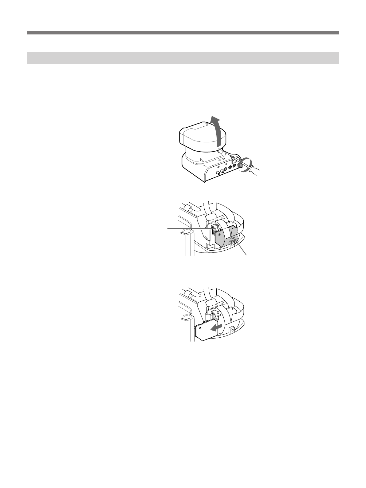
When You Discard Camera Unit
For environmental reasons, take out a lithium battery from the camera and
discard it accordingly.
1 Remove the screw at the rear of the camera head using a Phillips type
2 Remove the stopper and connector.
screw driver and detach the cabinet.
Stopper
Connector
3 Remove the lithium battery together with the board.
Dispose of the lithium battery according to the local law.
6 Precautions
Page 7

Features
The PCS-3000/3000P Rollabout Package can connect among three remote
groups via ISDN lines*. It sends and receives images and sound, allowing
you to have virtual face-to-face meetings with people in other cities or
countries.
The system accommodates up to three participants in one location.
You can add an additional PCS-A300 Microphone (not supplied) for
additional participants.
*You can install an optional interface board for connection via the V.35
interface or for connection among four remote parties.
Connects among three locations (Multi meeting)
The PCS-3000/3000P Rollabout Package allows you to connect among
three locations and send and receive a still picture.
If you install the optional PCS-I300 BRI Board into the Rollabout
Processor, you can connect among four locations. When the remote party
holds a multi meeting, only you can end a meeting and other parties can
continue their meeting.
International standards
The PCS-3000/3000P Rollabout Package complies with ITU-T standards,
for easy connection with remote parties overseas.
(The ITU-T standard has been defined by WTSC (former CCITT).)
WTSC: World Telecommunications Standardization Committee
ITU: International Telecommunication Union
AT (Automatic target tracking) function
In addition to high-speed pan/tilt action, AT (automatic target tracking)
feature allows you to tracks a subject having the memorized color and
brightness automatically.
Easy operation
The system is easy to operate. All operations are carried out by selecting
icons with the Remote Commander.
Echo canceler
A built-in echo canceler decreases sound echo from walls in the meeting
room, allowing for clear sound reproduction.
Video presentation stand
TV monitor
If you use the VID-P100 Video Presentation Stand, you can enhance your
meeting with still and motion pictures.
The TV monitor can be used as a TV by connecting with a VCR.
Features 7
Page 8

Page 9
Using the Remote Commander
To operate the Remote Commander
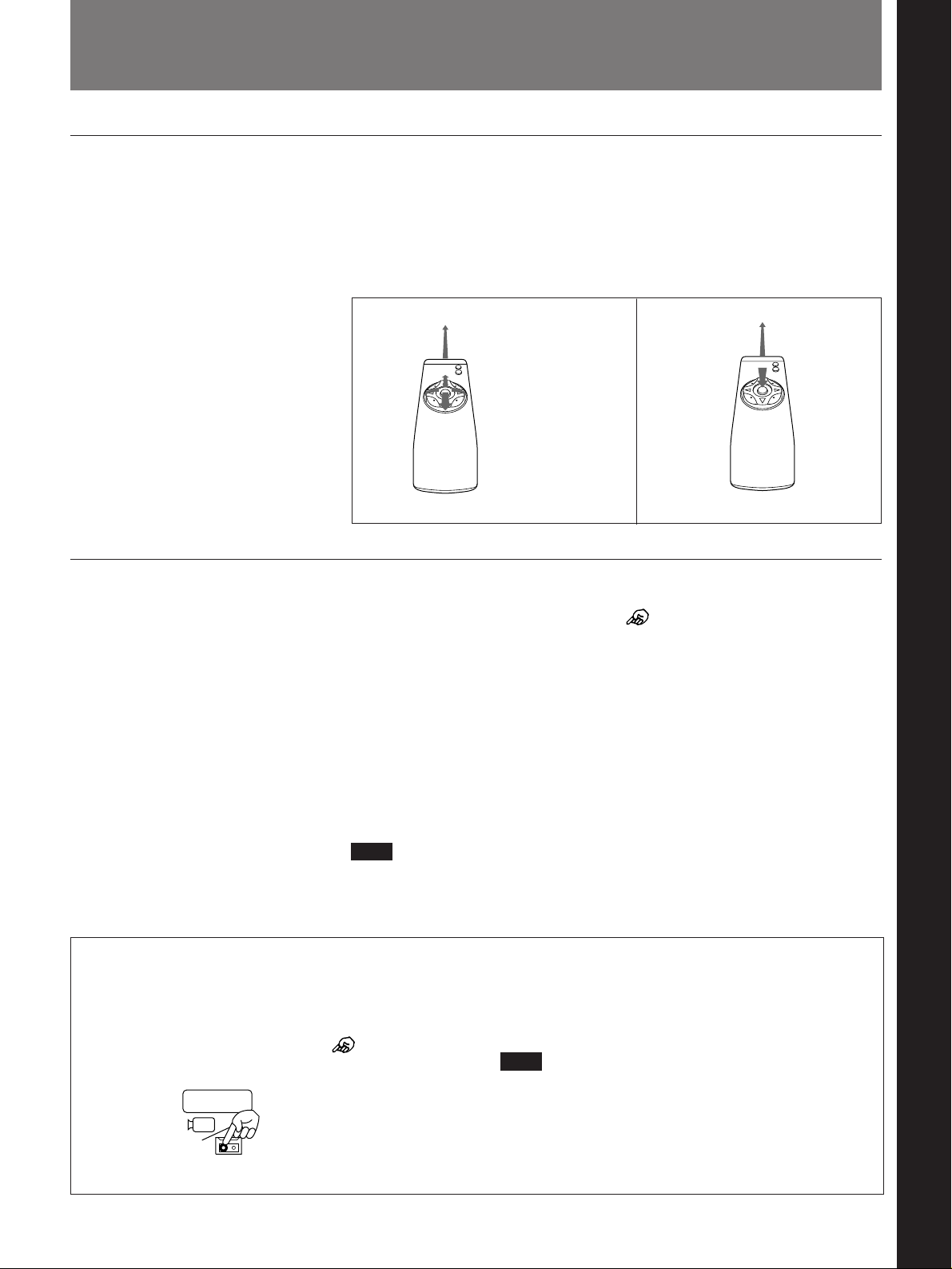
You can operate the PCS-3000/3000P Rollabout Package with the Remote
Commander. The Remote Commander has a 4-direction cursor button (Z,
4, z, $) and an execute (middle) button. The functions in the Rollabout
Package can be conducted with these two buttons. When using the Remote
Commander, point it at the camera unit on top of the TV monitor.
Chapter 1 Using the Basic System
Chapter 1
To select a function
Camera unit
Press or hold down
the cursor button (Z,
4, z, $) in the
desired direction.
Press the execute (middle) button.
Using the Remote Commander
Camera unit
To select a function, move the cursor ( ) (the cursor appears in each
menu) to the desired icon.
To move the cursor, press the cursor button in the desired direction, and
release it when the cursor reaches the desired position.
After placing the cursor at the desired position, press the execute button to
select and execute the function.
To move the cursor
To move the cursor continuously, hold down the cursor button in the
desired direction. To move the cursor one increment, press the cursor
button once in the desired direction.
Note
You cannot operate the TV monitor with the Remote Commander. To
operate the TV monitor, use the remote control unit for the TV monitor or
the controls on the TV itself.
Icon conventions used in this manual
Icons are graphic symbols appearing on the TV
monitor. Each icon represents a function of the
Rollabout Processor. In this manual, “Select
[XXX]” means moving the cursor (
desired icon and pressing the execute button.
INPUT
) to the
For example, “Select [INPUT]” means moving the
cursor to the INPUT icon and pressing the execute
button.
Note
The illustrations in this manual are of the PCS-3000
model, but also apply to the PCS-3000P version.
These two models are virtually identical, the only
difference being that the PCS-3000 version has an
AC OUT socket.
Chapter 1 Using the Basic System 1-1
Page 10
Basic System Connections
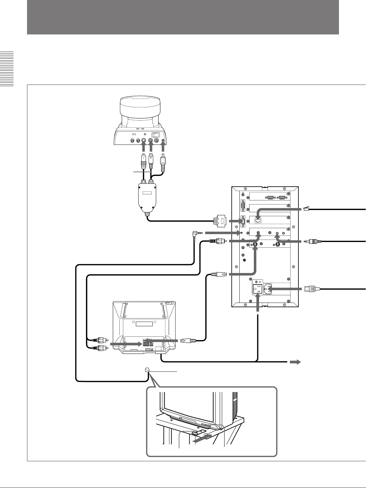
The PCS-3000/3000P is a basic system that can be enhanced with variety
of optional equipment. This chapter describes the operation of the basic
system.
Chapter 1
PCS-C300/C300P Camera Unit
to S VIDEO OUT
to VISCA IN
Camera unit cable
(2.3 m, 7.5 ft (supplied))
Audio cable (1 m, 3.3 ft (supplied))
The camera unit and the microphone
receive their power from the Rollabout
Processor via their connection cables.
Set the POWER and BACKUP
switches on the camera unit to ON.
to DC IN
Rollabout Processor
to ISDN A
to CAMERA UNIT
to IR OUT
to AUDIO MIC1
to AUDIO
LINE
OUT
to AUDIO1
TV monitor
to VIDEO 1
INPUT S
VIDEO
AC power cord
IR repeater (supplied)
Insert below the remote sensor of TV
monitor
IR repeater (supplied)
to VIDEO
OUT
MONITOR
S VIDEO
connecting cable
(1.3 m, 4.3 ft
(supplied))
Remote sensor
to AC IN
to AC OUT
(PCS-3000 only)
to AC outlet
(PCS-3000P only)
1-2 Chapter 1 Using the Basic System
Page 11
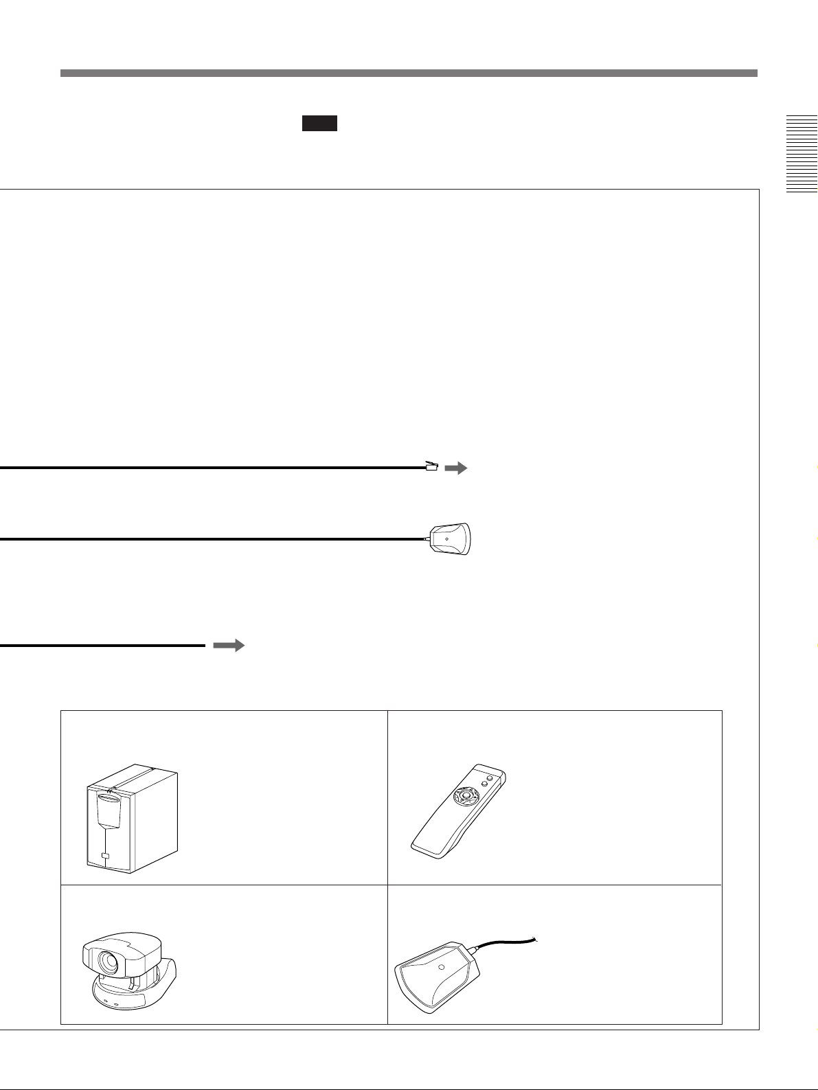
ISDN modular cable (3 m, 9.8 ft)
(PCS-3000P: supplied)
(PCS-3000: not supplied)
Note
Make sure to turn off the power of the Rollabout Processor before making
any connections.
Chapter 1
to ISDN
PCS-A300 Microphone
(8 m, 26 ft (supplied))
AC power cord (2.5 m, 8.2 ft (supplied))
Basic system equipment
The PCS-3000/3000P Rollabout Package forms the basis of the PCS-3000 series system. The Rollabout
Package consists of the following items:
PCS-P300/P300P
Rollabout Processor
PCS-C300/C300P
Camera Unit
to AC outlet
Contains the video codec,
audio codec, echo canceler,
network interfaces and
system controller.
Monitors the participants.
Normally, installed on top of
the TV monitor. (Use the
supplied velcro tapes to
secure the installation, if
needed.)
PCS-R500
Remote Commander
PCS-A300
Microphone
Controls the system via
menus on a TV monitor. It
can also be used to turn on
the system and TV monitor
and activate the muting
function to prevent the
conversations from being
transmitted to the remote
party.
Microphone unit; allows
you to accommodate extra
two or three participants.
Chapter 1 Using the Basic System 1-3
Page 12
Menus
To display a menu
Chapter 1
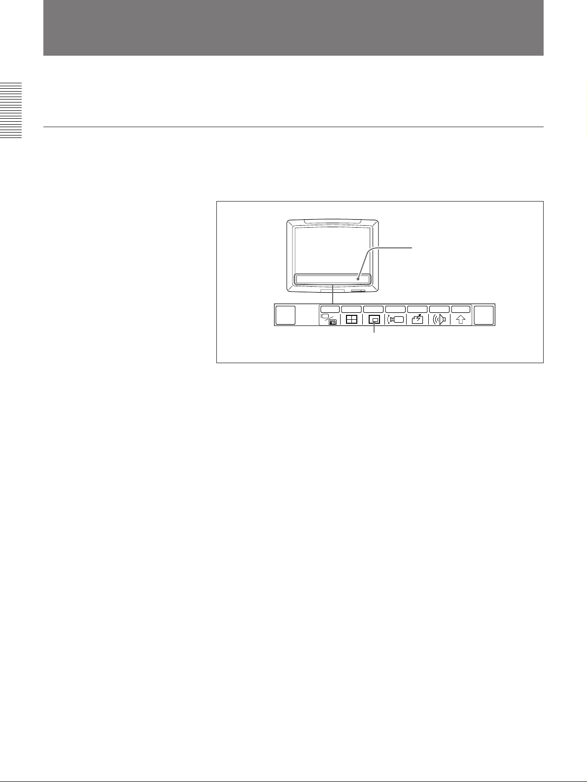
The PCS-3000/3000P Rollabout Package has three major menus (QUICK
DIAL, QUICK, and MAIN) and various operational menus.
During a video meeting, all necessary operations are conducted via menus
on the TV monitor screen. To display a menu, press the cursor button or
execute button. The menu which was displayed last appears on the screen.
Menu
MULTI P in P CAMERA SEND AUDIO OTHER
QUICK
DIAL
INPUT
END OF
MEETING
Icon
Menu display (MAIN menu)
A menu consists of icons, with each specific function.
If an icon appears dim, that particular function is inactive and cannot
be used.
If the menu has disappeared, press the cursor or execute button. The
menu that was displayed last appears again.
(If the menu is not used for six seconds, it will disappear.)
1-4 Chapter 1 Using the Basic System
Page 13
Switching Menus
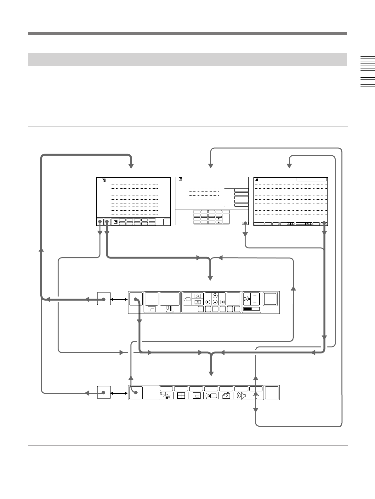
When you turn on the PCS-3000/3000P Rollabout Package the picture of
the local camera appears on the TV monitor. If you operate the Rollabout
Package with the Remote Commander, the QUICK DIAL, DIAL LIST or
MANUAL DIAL menu appears on the TV monitor.
The menus are switched as follows:
Chapter 1
QUICK DIAL menu
# 1
LIST
# 2
# 3
# 4
# 5
# 6
# 7
# 8
# 9
# 10
MAIN
QUICK
MENU
MENU
QUICK
DIAL
Select
[QUICK
MENU].
Select
[MAIN
MENU].
When it is not on
line, select [QUICK
DIAL].
MANUAL DIAL menu DIAL LIST menu
MANUAL DIAL
A1
A2
B1
B2
1
2
3
delete
ABC
DEF
4
5
6
GHI
JKL
MNO
PQRS
# 1
# 2
# 3
# 4
# 5
SYSTEM
# 6
# 7
# 8
# 9
OFF
# 10
7
∗
copy
TUV
WXYZ
8
9
0
#
LINE I/F
BRI
LINE RATE
AUTO
AUDIO BAND
7K
T.120/H.281
OFF
H.261
VIDEO MODE
15FPS
clear
DIAL
Select
[EXIT].
LIST
001
002
003
004
005
006
007
008
009
010
EXIT
SETUPDELETE PAGE EXITDIALSELECTMULTI
SELECTED
011
012
013
014
015
016
017
018
019
020
Select
[EXIT].
QUICK menu
MAIN
MENU
P in P
OBJECT
PRESET
FAR
END
FA B C D E
SYSTEM
OFF
When it is on line,
select [MAIN
MENU].
QUICK
DIAL
When it is not on
line, select [QUICK
DIAL].
When it is on line,
select [QUICK
MENU].
QUICK
MENU
MAIN menu
INPUT MULTI P in P CAMERA SEND AUDIO OTHER
Chapter 1 Using the Basic System 1-5
Select [DIAL LIST]
from [OTHER].
END OF
MEETING
Select [MANUAL DIAL]
from [OTHER].
Page 14
Menus
QUICK DIAL menu
Chapter 1
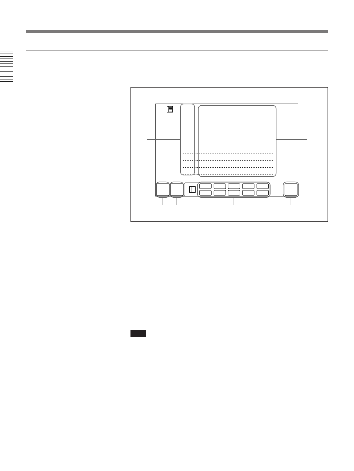
Parties registered on the QUICK DIAL menu can be called up quickly and
easily. Up to 10 parties may be registered.
# 1
LIST
# 2
# 3
# 4
QUICK
MENU
# 5
# 6
# 7
# 8
# 9
# 10
# 1
# 6
# 2
# 7
# 3
# 8
# 4
# 9
# 5
# 10
SYSTEM
OFF
12
MAIN
MENU
4
356
QUICK DIAL menu
1 Index number (#1 – #10) (page 2-1)
2 Remote party name list (page 2-1)
3 MAIN MENU – switches to the MAIN menu. (page 1-5)
4 QUICK MENU – switches to the QUICK menu. (page 1-5)
5 Quick dial number (#1 – #10) – dial up the remote parties. Numbers for
which no party has been registered cannot be connected. (page 3-4)
6 SYSTEM OFF – turns off the system. (page 3-2)
To display the QUICK DIAL menu
Select [QUICK DIAL] from the MAIN menu while the Rollabout
Processor is not in a meeting. The QUICK DIAL menu appears.
Note
When connecting with a remote party, the QUICK DIAL icon in the
MAIN menu is replaced by a QUICK MENU icon. If you select [QUICK
MENU], the QUICK menu appears.
1-6 Chapter 1 Using the Basic System
Page 15
QUICK menu
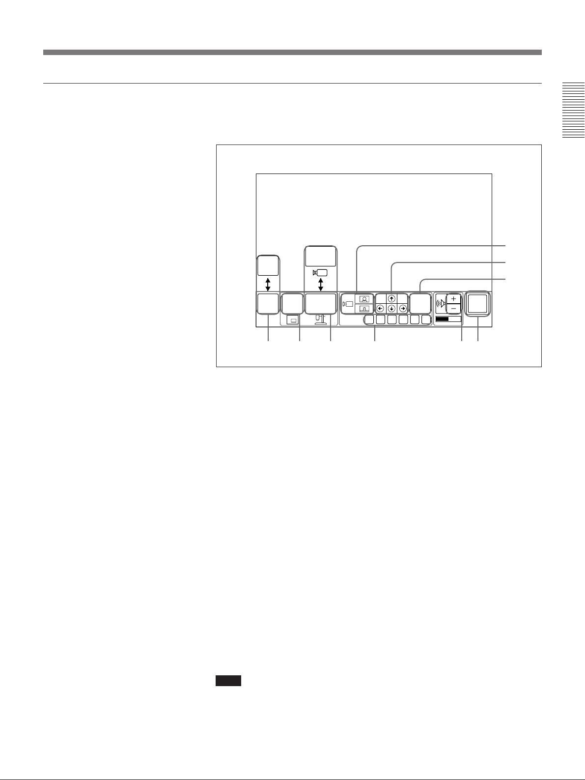
The QUICK menu lists various icons that are used frequently during a
meeting. You can conduct most meetings using these icons only.
Chapter 1
QUICK
DIAL
MAIN
6
7
5
MAIN
MENU
P IN P OBJECT
PRESET
FAR
END
FA B C D E
SYSTEM
OFF
984321
QUICK menu
1 MAIN MENU/QUICK DIAL – switches to the MAIN or QUICK
DIAL menu. (page 1-5)
2 P IN P – displays an inset window on the monitor screen. (page 1-11)
3 OBJECT/MAIN– displays the image from the equipment connected to
the VIDEO IN AUX1 jack or from the camera unit.
When the OBJECT icon is displayed, the picture from the camera unit
is displayed on the monitor screen. When the MAIN icon is displayed,
the picture from the equipment connected to the VIDEO IN AUX1 jack
is displayed. (page 4-3)
4 PRESET (A to F) – recalls preset camera angles, zoom and camera
brightness settings. (page 1-15)
5 Camera zoom adjustment – adjusts the zoom. (pages 1-13, 4-6)
6 Camera angle adjustment – adjusts the camera angle. (page 1-13)
7 FAR END – specifies the camera (local or remote) when adjusting
camera angle and zoom. (page 1-12)
8 Volume – adjusts the volume. (page 1-9)
9 SYSTEM OFF – turns off the system. (page 3-2)
To display the QUICK menu
Select [QUICK MENU] from the MAIN menu while the Rollabout
Processor is in a meeting. The QUICK menu appears.
Note
When not connecting with a remote party, the QUICK icon in the MAIN
menu is replaced by a QUICK DIAL icon. If you select [QUICK DIAL],
the QUICK DIAL menu appears.
Chapter 1 Using the Basic System 1-7
Page 16
Menus
MAIN menu
Chapter 1
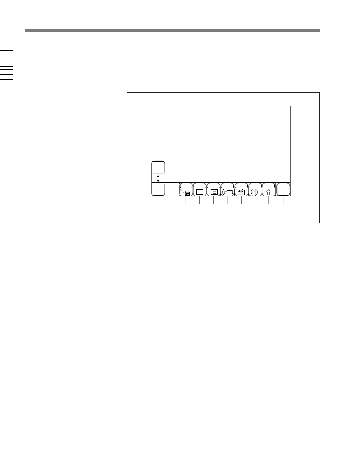
The MAIN menu is used for making various settings and input/output
selections. You can access the QUICK or QUICK DIAL menu from the
MAIN menu.
QUICK
DIAL
MULTI P IN P CAMERA SEND AUDIO OTHER
QUICK
MENU
INPUT
END OF
MEETING
1 92 3 4 5 6 7 8
MAIN menu
1 QUICK MENU/QUICK DIAL – switches to the QUICK or QUICK
DIAL menu. (page 1-5)
2 INPUT – selects external video equipment. You can select the input
from local or remote equipment. Selecting [SOURCE VIEW] in the
INPUT sub-menu produces a full-size screen of the selected picture.
(page 1-10)
3 MULTI – used to change screen format when connecting with several
parties or when connecting with MCU to perform the chairman control.
(pages 1-24,1-26)
4 P IN P – displays an inset window on the monitor screen. (page 1-11)
5 CAMERA – switches to the CAMERA menu. (page 1-13)
6 SEND – sends the image to the remote party. (page 4-4)
7 AUDIO – adjusts the volume and selects external audio equipment.
(pages 1-9, 4-8)
8 OTHER – used for registering remote parties, or adjusting settings in
the SETUP menu; also accesses the DIAL LIST menu and the
MANUAL DIAL menu. (pages 1-5, 2-1, 2-9)
9 END OF MEETING – disconnects the line or turns off the system.
(pages 3-2, 3-11)
1-8 Chapter 1 Using the Basic System
To display the MAIN menu
Select [MAIN MENU] from the current menu. If the DIAL LIST or
MANUAL DIAL menu appears, select [EXIT].
Page 17
Basic Adjustments
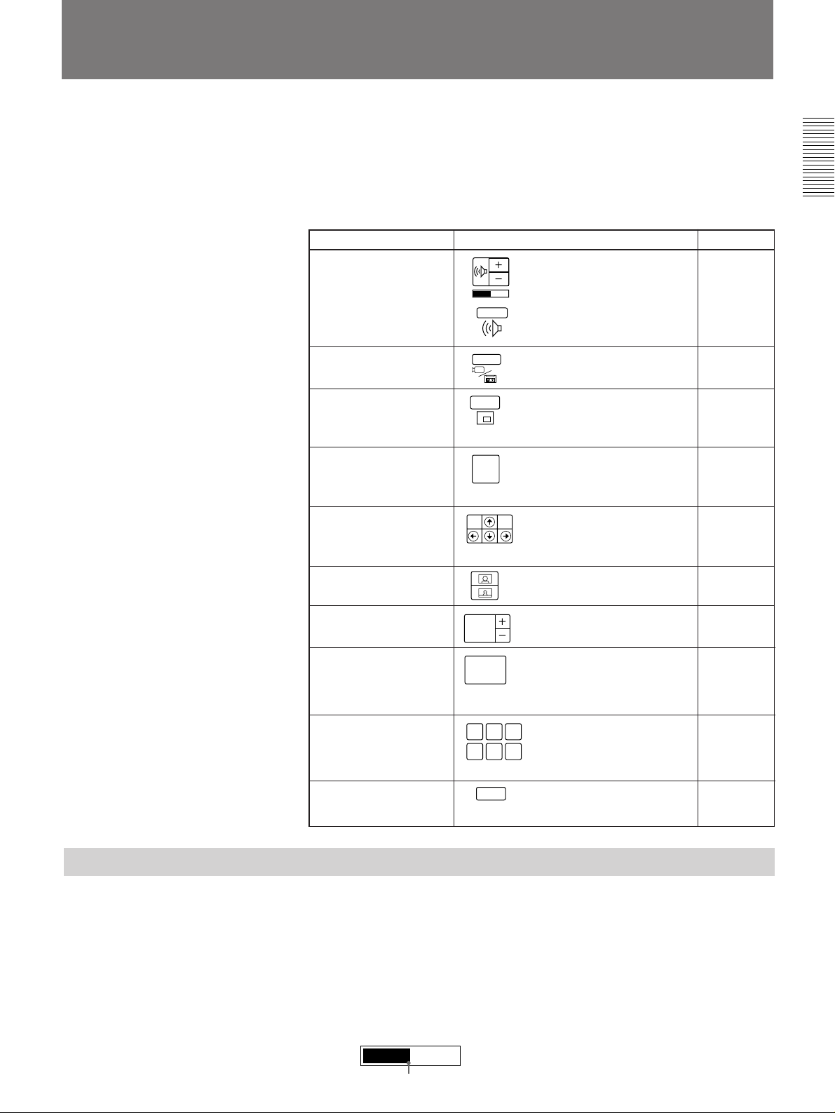
You can make adjustments to audio and video settings during a meeting.
The following sections describe how to adjust volume, the picture-inpicture window, and the camera (angle, focus, zoom, and AT function).
You can preset six camera angles, zoom and camera brightness settings.
For details on turning on the system, see “Turning the System On/Off” on page 3-
1.
Chapter 1
Function Page
Volume adjustment QUICK menu page 1-9
Picture selection MAIN menu page 1-10
Displaying an inset QUICK menu, MAIN menu, page 1-11
window CAMERA menu
Camera selection QUICK menu page 1-12
Angle adjustment QUICK menu page 1-13
Zoom adjustment QUICK menu, CAMERA menu page 1-13
Focus adjustment CAMERA menu page 1-13
Icon
P in P
FOCUS
AUTO
AUDIO
INPUT
FAR
END
MAIN menu
CAMERA menu
CAMERA menu
Adjusting the Volume
Saving the camera CAMERA menu page 1-14
angle, zoom and
brightness setting
Recalling the camera CAMERA menu page 1-15
angle, zoom and QUICK menu
brightness setting
Tracking a subject CAMERA menu page 1-15
automatically
PRESET
A B C
D E F
AT
You can adjust the volume either from the QUICK or MAIN menu.
To adjust the volume in the MAIN menu, select [AUDIO]; then select
volume icon [+] or [–].
To adjust the volume in the QUICK menu, follow the step below:
Select [+] or [–] from the QUICK menu.
[+] to increase the volume. [–] to decrease the volume.
If feedback occurs, decrease the volume.
Selected volume level
Chapter 1 Using the Basic System 1-9
Page 18
Basic Adjustments
Chapter 1
Selecting the Picture
Note
You have to set the volume level on the TV monitor at first.
For details on setting the initial volume level on the TV monitor, see “Setting the
Initial Volume Level on the TV Monitor” on page 2-24.
You can select the picture from both local and remote sites equipment.
Notes
•Items at the left are only displayed when it is on line.
•Items at the left are displayed even if the video equipment is not
connected to the remote party. When you select the item which does not
have equipment, the picture does not appear.
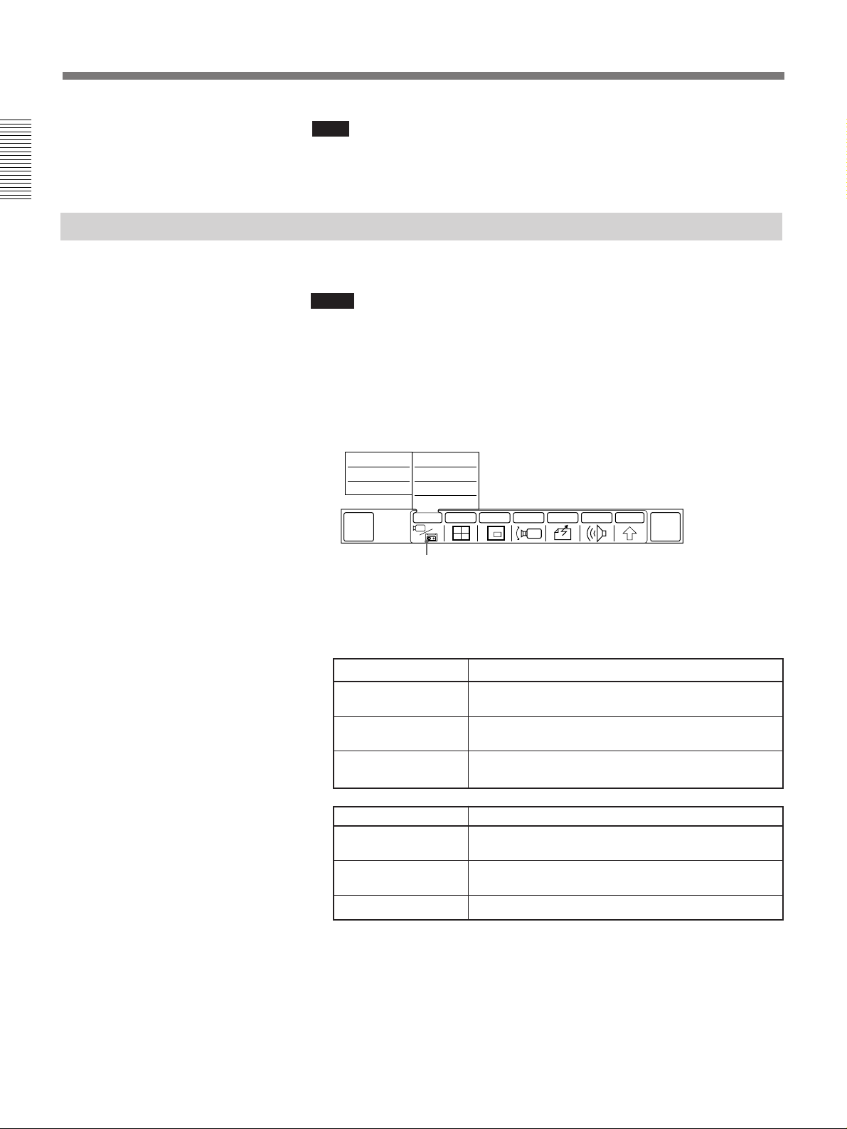
1 Select [INPUT] from the MAIN menu.
The INPUT sub-menu appears.
FAR
AUX2
FAR
AUX1
FAR
MAIN CAM
QUICK
MENU
NEAR
AUX2
NEAR
AUX1
NEAR
MAIN CAM
SOURCE VIEW
MULTI P in P CAMERA SEND AUDIO OTHER
INPUT
END OF
MEETING
[INPUT]
2 Select the picture.
Select the local picture at the right of the INPUT sub-menu, and
remote picture at the left.
Items at the left Selected picture
FAR AUX2 Displays picture from equipment connected to the
VIDEO IN AUX2 jack at the remote party.
FAR AUX1 Displays picture from equipment connected to the
VIDEO IN AUX1 jack at the remote party.
FAR MAIN CAM Displays picture from main camera at the remote
Items at the left Selected picture
NEAR AUX2 Displays picture from equipment connected to the
NEAR AUX1 Displays picture from equipment connected to the
NEAR MAIN CAM Displays picture from main camera at the local party.
If you select [SOURCE VIEW]
•A full-sized screen of the local picture is produced.
•When the still picture is displayed, the picture returns to the moving
picuture.
party.
VIDEO IN AUX2 jack at the local party.
VIDEO IN AUX1 jack at the local party.
1-10 Chapter 1 Using the Basic System
Page 19
Monitoring Yourself in the Inset Window
The inset window allows you to monitor your own party while viewing the
remote party.
To open the inset window or change its position
You can display or remove the inset window and change its position.
You can open the inset window from any menus except the QUICK DIAL,
DIAL LIST and MANUAL DIAL menus.
The following example shows you how to open the inset window from the
QUICK menu.
Select [P in P] from the QUICK menu.
An inset window appears if the inset window is not displayed.
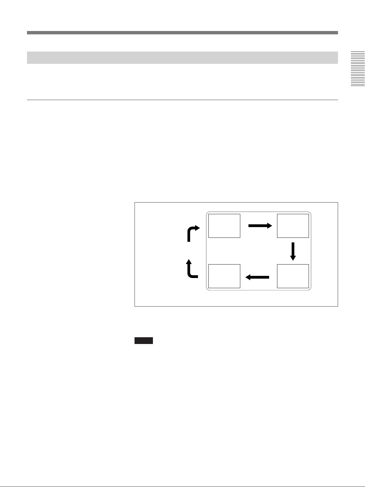
Each time you select [P in P], the inset window moves as follows:
Chapter 1
The inset window
disappears.
TV monitor
When the inset window is on screen, it shows the picture being sent to the
remote party.
Notes
•The inset window does not appear when your system is not connected to
a remote party.
•When the main screen is showing a still picture, the inset window is not
displayed.
•You cannot use the Picture in Picture function when the main screen is
showing a picture of your party even while the line is connecting.
Chapter 1 Using the Basic System 1-11
Page 20
Basic Adjustments
Adjusting Local and Remote Cameras
Chapter 1
To select the camera to adjust
You can adjust the local camera to obtain the best viewing results.
You can also adjust the remote camera and adjust the image being sent
from that camera.
Notes
•You cannot control a remote camera when it is on line to several parties
at once. See “Holding a Meeting With Multiple Remote Parties” on page
1-19.
•A malfunction may occur if the local and remote parties try to adjust the
same camera at the same time.
•You cannot control a remote camera during meeting if the remote party is
using other than a PCS-5000/4000/3000/2000 series system and H.281 is
not selected as the remote camera control system.
In order to adjust a camera, you must select which camera you want to
control – local or remote. Selection and adjustment can be done in the
CAMERA or QUICK menu.
The following describes selection and adjustment from the QUICK menu:
Note
Focus, preset settings, and AT (automatic target tracking) function can be
set only from the CAMERA menu.
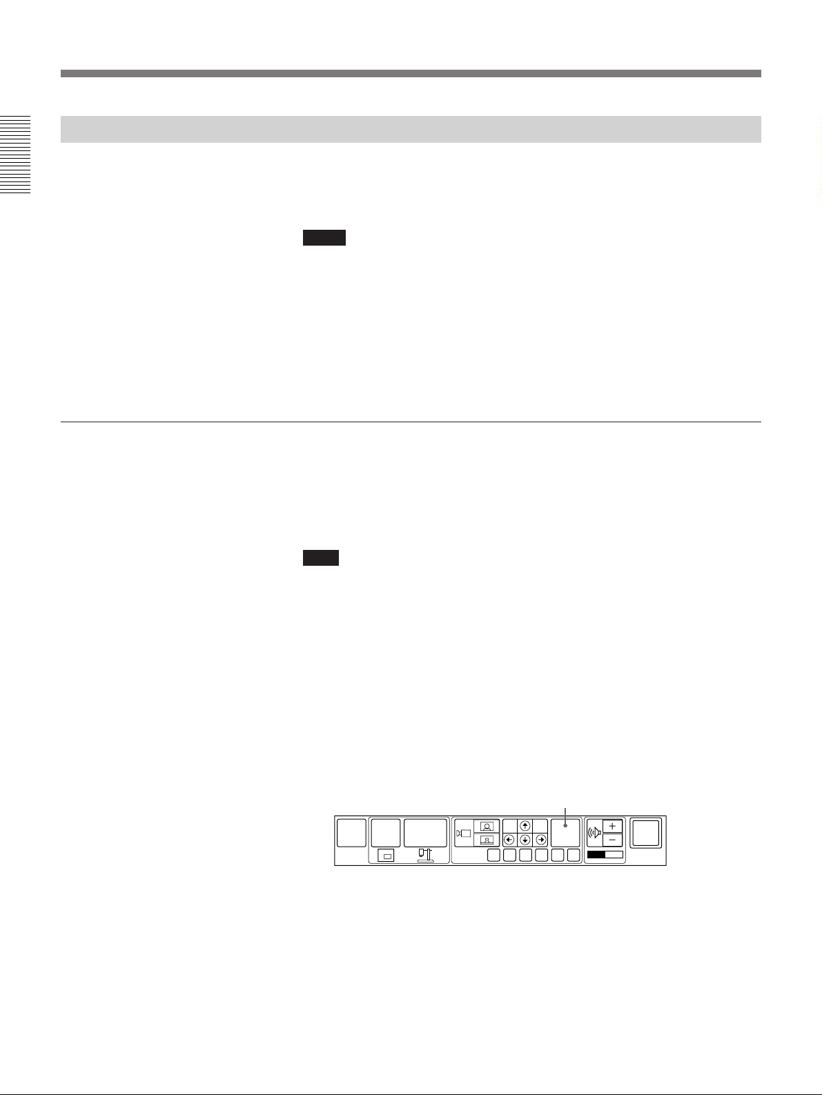
1 Select the camera (local or remote) you want to adjust with the FAR
END icon.
Each time you select [FAR END], the color of the icon is switched
between gray and blue.
While the icon is gray, you can operate the local camera.
While the icon is blue, you can operate the remote camera.
(You cannot control a remote camera during meeting if the remote
party is using other than a PCS-5000/4000/3000/2000 series system
and H.281 is not selected as the remote camera control system.)
[FAR END]
MAIN
MENU
P in P
OBJECT
PRESET
FAR
END
FA B C D E
SYSTEM
OFF
1-12 Chapter 1 Using the Basic System
2 Adjust the camera.
You can adjust the camera angle and zoom, and recall the camera
angle and zoom settings from the QUICK menu.
For details, see “To adjust the camera angle and zoom” on next page.
Page 21

To adjust the camera angle and zoom
To adjust the camera angle
Select [>][?][.][/] to view any areas not currently covered by the
camera.
Chapter 1
To adjust the focus
Outside the
Within the camera’s scope
camera’s scope
Adjusting the camera angle
To adjust the zoom
Select [
] to zoom in or [ ] to zoom out.
Focus adjustment and the AT function can be performed only through the
CAMERA menu.
Switches the camera between local and remote.
Adjusts the focus.
Activates the AT function.
Adjusts the zoom.
AT
P in P
FOCUS
AUTO
PRESET
ADBEC
Displays an inset window.
Stores or recalls a setting.
CAMERA menu
1 Select [CAMERA] from the MAIN menu.
The CAMERA menu is displayed.
MULTI P in P CAMERA SEND AUDIO OTHER
FOCUS
AUTO
INPUT
PRESET
[CAMERA]
ADBEC
F
Chapter 1 Using the Basic System 1-13
QUICK
MENU
AT
P in P
F
Adjusts the angle.
FAR
END
END OF
MEETING
EXIT
FAR
END
EXIT
(Continued)
Page 22
Basic Adjustments
Chapter 1
2 Adjust the camera.
You can adjust the camera angle, focus, and zoom. You can also store
or recall a camera angle and zoom setting. (See the figure on the
previous page.)
3 Select [EXIT] once you have finished making adjustments.
The CAMERA menu disappears and the MAIN menu appears.
To switch between auto and manual focus
Select [FOCUS AUTO] for auto focus. For manual focus, use the plus/
minus [+], [–] buttons beside [FOCUS AUTO].
We recommend you to select [FOCUS AUTO] since the camera unit will
automatically adjust itself for the best focus.
To adjust the focus manually
Use the plus/minus [+], [–] buttons beside [FOCUS AUTO].
[–] moves the point of focus closer to the camera unit.
[+] moves the point of focus further away from the camera unit.
Presetting Angle, Zoom And Camera Brightness
You can store six angle, zoom, and camera brightness settings. Once a
setting is saved, you can easily recall the setting.
Note
Set the BACKUP switch at the rear of the camera unit to ON if the
Rollabout Processor is turned off completely. Otherwise, the memories of
the preset settings are erased (page 1-16).
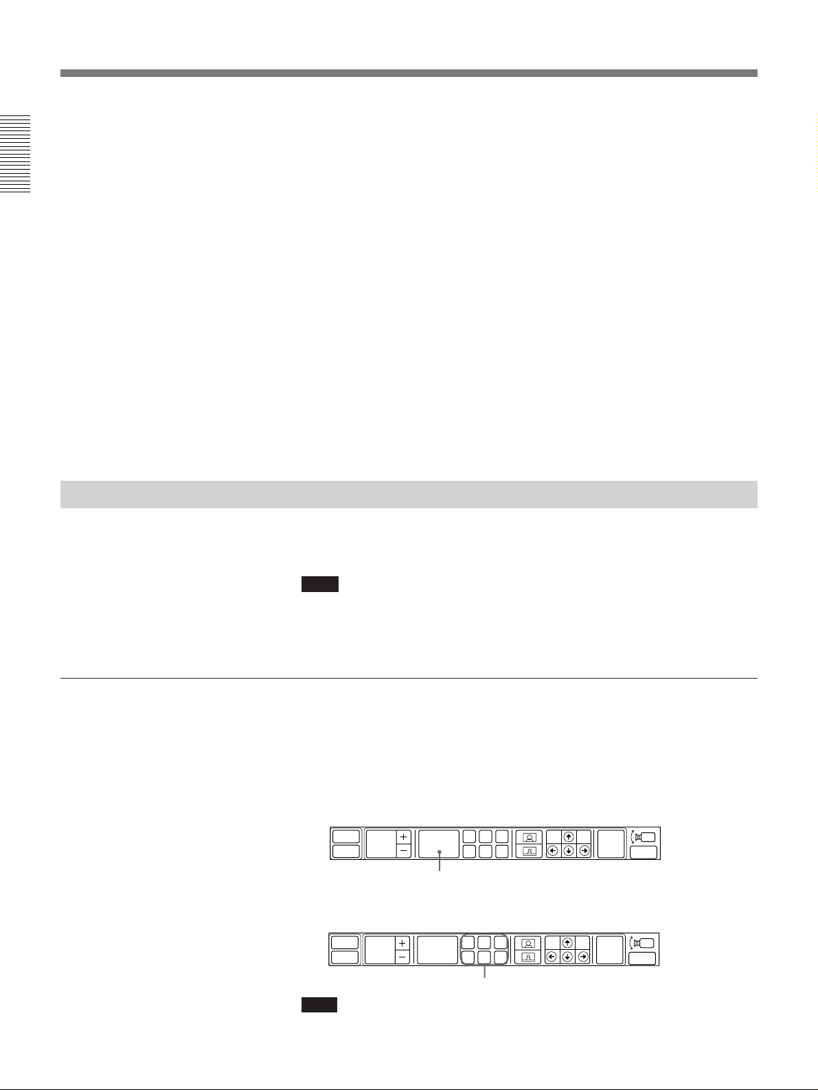
To store a setting
1 Set the camera angle, zoom, and camera brightness.
For details on camera angle and zoom settings, see “ To adjust the camera
angle and zoom” on page 1-13, and for on camera brightness setting, see
“Adjusting the Camera Brightness” on page 2-22.
2 Select [PRESET] from the CAMERA menu.
AT
P in P
FOCUS
AUTO
[PRESET]
PRESET
ADBEC
3 Select a letter (A to F) under which the setting will be stored.
The setting will be stored under that letter.
AT
P in P
FOCUS
AUTO
PRESET
ADBEC
FAR
F
F
END
FAR
END
EXIT
EXIT
1-14 Chapter 1 Using the Basic System
Preset letter
Note
Once you preset the angle and zoom, the focus automatically switches to
auto focus setting.
Page 23
To recall a setting
Select a setting letter (A to F).
The camera is then adjusted to the setting stored under that letter.
Tracking a Subject Automatically — AT (Automatic Target Tracking)
Function
You can have the camera memorize certain color and brightness so that
automatically tracks a subject having the memorized color and brightness.
If a subject almost goes out of the screen, the camera performs the pan/tilt
action so that the subject is placed in the middle of the screen.
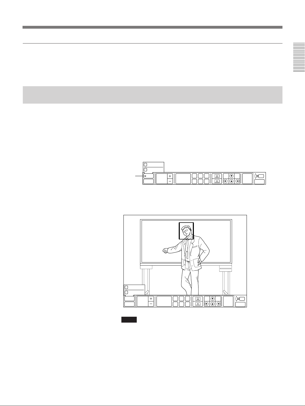
1 Select [AT] from the CAMERA menu.
The AT sub-menu appears and the frame is displayed on the screen.
AUTO ZOOM
TRACK
[AT]
AT
P in P
FOCUS
AUTO
PRESET
ADBEC
F
FAR
END
Chapter 1
EXIT
2 Select [?], [>], [/], [.] to perform the pan/tilt operation so that a
subject is placed into the frame.
AUTO ZOOM
TRACK
AT
FOCUS
AUTO
P in P
Notes
•Be sure to place the subject so that the portion uniform in brightness
and color is in the frame.
•The camera might not recognize a subject if the portion different from
the subject in brightness and color, such as the backdrop, is placed
together in the frame.
PRESET
ADBEC
FAR
F
END
EXIT
(Continued)
Chapter 1 Using the Basic System 1-15
Page 24

Basic Adjustments
Chapter 1
3 Select [TRACK].
TRACK check box changes to blue.
Try moving the subject to see if the frame tracks it automatically.
When the frame tracks the subject, proceed with the step 4.
When the frame does not track the subject, repeat the steps 2 and 3
until the frame starts tracking the subject while adjusting the lighting
and the position of the subject so that the color and brightness of the
subject is optimized.
4 Select [AT].
The AT (automatic target tracking) function starts and the frame
disappears from the screen.
To cancel the AT (automatic target tracking) function
Select [TRACK] again so that the color of the TRACK check box returns
to the original color.
About Backup
To keep the size of the memorized subject as is
After performing the pan/tilt operation so that a subject is placed into the
frame, select [AUTO ZOOM].
To cancel the function, select [AUTO ZOOM] again so that the color of the
AUTO ZOOM check box changes to blue.
Then, repeat the step 3.
If the frame is repeatedly extended to the full screen
The camera does not recognize the subject. Select [TRACK] again and go
back to the step 2.
If the lamp at the side of the lens lights up
The camera is not capturing the memorized subject correctly.
In this case, perform the pan/tilt operation so that the subject comes into
the screen. Or have the subject memorized onto the camera again.
The memories of the preset and clock settings are erased when the POWER
switch on the camera unit is set to OFF. To retain those memories, set the
BACK UP switch at the rear of the camera unit to ON.
1-16 Chapter 1 Using the Basic System
Notes
•In the camera unit, the built-in lithium battery acts as the power source for
retaining the memories and is kept charged as long as the system is used.
If the system is used for shorter period of time with the BACKUP switch
set to ON, however, the battery is gradually discharged. Besides if you do
not use the system at all for almost 12 weeks, the battery is completely
discharged. To retain the memories of the settings, you should recharge
the battery.
•To recharge the battery, connect the camera unit to the Rollabout
Processor and leave it for approximate 48 hours with the POWER switch
on the camera unit set to ON.
Page 25

Muting Local Conversations (Mute Function)
You can mute local conversations by pressing the MIC MUTE button on
the Remote Commander.
If you press the MIC MUTE button, local conversations will not be sent to
the remote party.
When local conversations are muted, the mute mark (
the upper-right corner of the TV monitor.
To cancel muting
Press the MIC MUTE button again.
The mute mark (
) disappears.
Chapter 1
MIC MUTE button
) is displayed at
Chapter 1 Using the Basic System 1-17
Page 26
Checking Connection Status
During a meeting, you can check the status of your connections.
Chapter 1
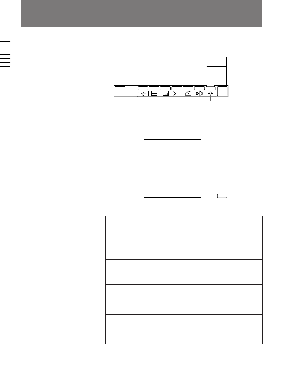
1 Select [OTHER] from the MAIN menu.
The OTHER sub-menu appears.
QUICK
MENU
INPUT MULTI P in P CAMERA SEND AUDIO OTHER
2 Select [STATUS].
The STATUS list appears.
CODEC:
LINE I/F:
NUMBER OF LINE:
LINE RATE:
AUDIO MODE (Enc):
AUDIO MODE (Dec):
VIDEO MODE:
FRAME RATE:
FAR END CAM CONTROL:
PCS-5000
BRI
2
64K
G.728
G.728
H.261 CIF
15
SONY
SETUP
STATUS
DTMF
T.120
DIAL LIST
MANUAL DIAL
[OTHER]
END OF
MEETING
EXIT
The STATUS list allows you to check the following items:
Item Meaning
:
CODEC ITU-T
PCS-2000: The remote party is using a PCS-2000
PCS-5000: The remote party is using a PCS-5000/
LINE I/F The line interface presently in use
NUMBER OF LINE The number of lines presently in use
LINE RATE The present transmission rate
AUDIO MODE (Enc) The present audio encoding system at the local
party
AUDIO MODE (Dec)
The present audio encoding system at the remote
party
VIDEO MODE The present video encoding mode
FRAME RATE The present maximum frame rate of sending a
motion picture
FAR END CONTROL OFF: No control.
H.281: The remote camera control form based on
SONY:The remote camera control form based on
Remote party is using equipment
conforming to standards
series system.
4000/3000 series.
H.281 standards.
Sony standards.
1-18 Chapter 1 Using the Basic System
Select [EXIT] to revert to the MAIN menu.
Page 27
Holding a Meeting With Multiple Remote Parties
The PCS-3000/3000P Rollabout Package allows for audio and video
connection among three different parties (PCS-5000/4000/3000 series
system) at the same time.
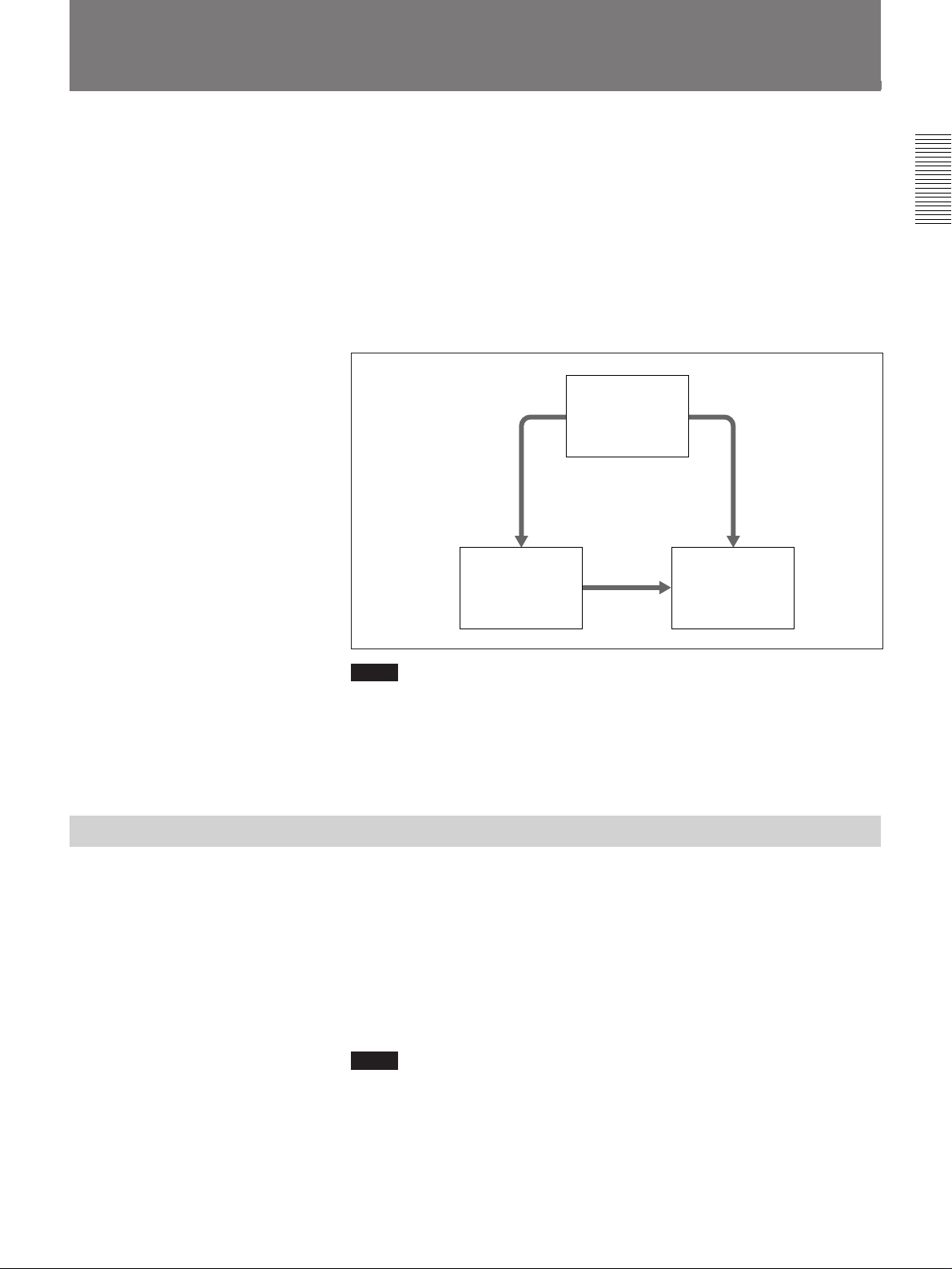
You begin a multi meeting by dialing and making line connection with
parties A and B. Once the lines have been connected, party A connects
automatically with party B to form the line connection setup indicated in
the following figure.
Once connections have been made, all three parties can meet as a single
group.
Local party
Chapter 1
Notes
•A multi meeting can only work when each party uses the PCS-5000/
4000/3000 series system.
•A multi meeting can only be held via the ISDN lines.
•During a multi meeting, you will not be able to adjust a remote party’s
camera.
Preparing for a Multi Meeting
Important
Before starting a multi meeting, check to see if you have the following:
•Entries for [LDN] in the SETUP menu have been completed.(See page 2-
13)
•The settings for [LINE RATE] and [AUDIO BAND] in the DIAL
SETUP menu are the same as each party.
•Set [AUDIO BAND] in the DIAL SETUP menu to 3.4K if you connect
each party at 1B (1B is 56/64Kbps) transfer rate.
Party A
Party B
Notes
•You cannot have a multi meeting when the settings above are wrong.
•You cannot have a multi meeting when there is only one remote party on
the line. When there is only one remote party, connect as normal
procedure.
Chapter 1 Using the Basic System 1-19
Page 28
Holding a Meeting With Multiple Remote Parties
Connecting with Other Parties
There are two ways to connect with the remote parties, depending on the
Chapter 1
setting method specified in the DIAL SETUP menu. To connect with the
unregistered remote parties, operate from the MANUAL DIAL menu.
Assign one index number for the two remote parties. Use this index
number to contact the other parties
In the DIAL SETUP menu, register party A in the A1 line, and party B in
the A2 line. Set [LINE I/F] to BRI-M, and [AUDIO BAND] to 3.4K.
For details on registering remote parties, see page 2-1.
Select each of the two remote parties to make a connection
Select the parties you want to connect with from the DIAL LIST menu one
by one.
Set up each of the unregistered remote parties to make a connection
Set up the parties you want to connect with from the MANUAL DIAL
menu one by one.
To make connection by selecting the index number registering multiple parties
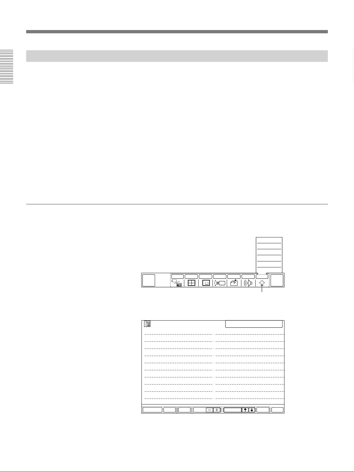
1 Select [OTHER] from the MAIN menu.
The OTHER sub-menu appears.
SETUP
STATUS
DTMF
T.120
DIAL LIST
MANUAL DIAL
QUICK
DIAL
INPUT MULTI P in P CAMERA SEND AUDIO OTHER
[OTHER]
END OF
MEETING
2 Select [DIAL LIST].
The DIAL LIST menu appears.
LIST
101 Boston Atlanta
102 Detroit Buffalo
103 Chicago Miami
104 Seattle San Francisco
105
106
107
108
109
110
SELECTED 101
111
112
113
114
115
116
117
118
119
120
1-20 Chapter 1 Using the Basic System
SETUPDELETE PAGE EXITDIALSELECTMULTI
Page 29

3 Select the index number for the parties you want to connect with, by
selecting [>] or [.].
The names of the selected parties change to blue.
The remote party index number appears in the SELECTED column at
the upper-right corner on the DIAL LIST menu.
•Select [PAGE +] to move to the next DIAL LIST page.
•Select [PAGE –] to move to the previous DIAL LIST page.
4 Select [DIAL].
The system starts dialing the selected parties.
Once connection has been made with all parties, the TV monitor screen
splits into four sections to display the remote parties as well as your
own group. The MAIN menu appears on the TV monitor.
The lines of each party are connected automatically. (A connects with
B.)
Once all line connections have been made, you can start the meeting.
Chapter 1
Party A
Local party
Party B
To make connections by selecting the remote parties from individual index number
1 Select [OTHER] from the MAIN menu.
The OTHER sub-menu appears.
QUICK
DIAL
INPUT MULTI P in P CAMERA SEND AUDIO OTHER
SETUP
STATUS
DTMF
T.120
DIAL LIST
MANUAL DIAL
[OTHER]
END OF
MEETING
2 Select [DIAL LIST].
The DIAL LIST menu appears.
LIST
001 Boston branch
002 Montreal branch
003 Chicago branch
004 Seattle branch
005 Buffalo branch
006 Detroit branch
007 San Francisco branch
008 Miami branch
009 Toronto branch
010 Ottawa branch
SELECTED 001
011 Dallas branch
012 Los Angeles branch
013 San Diego branch
014 New Orleans branch
015 Cleveland branch
016 Pittsburgh branch
017 Philadelphia branch
018 Atlanta branch
019 Denver branch
020 Memphis branch
SETUPDELETE PAGE EXITDIALSELECTMULTI
(Continued)
Chapter 1 Using the Basic System 1-21
Page 30

Holding a Meeting With Multiple Remote Parties
3 Select [MULTI].
The MULTI icon changes to blue.
4 Select the index numbers for the parties you want to connect with, by
Chapter 1
using [>] or [.] to select the parties and [SELECT] to decide one by
one.
The name of the selected party changes to blue.
You can choose up to two remote parties for a multi meeting.
The index numbers of the remote parties appear in the SELECTED
column at the upper-right corner on the DIAL LIST menu.
•If you select the wrong party, select [SELECT] again.
•Select [PAGE +] to move to the next DIAL LIST page.
•Select [PAGE –] to move to the previous DIAL LIST page.
5 Select [DIAL].
The system starts dialing the selected parties.
Once connection has been made with all parties, the TV monitor screen
splits into four sections to display the remote parties as well as your
own group. The MAIN menu appears on the TV monitor.
The lines of each party are connected automatically. (A connects with
B.)
Once all connections have been made, you can start the meeting.
Party A
Local party
To make connections with unregistered remote parties
Note
The settings having been fixed in the MANUAL DIAL menu will not be
stored. You then need to start over fixing the settings to use the MANUAL
DIAL menu.
1 Select [OTHER] from the MAIN menu.
The OTHER sub-menu appears.
QUICK
DIAL
INPUT MULTI P in P CAMERA SEND AUDIO OTHER
Party B
SETUP
STATUS
DTMF
T.120
DIAL LIST
MANUAL DIAL
END OF
MEETING
1-22 Chapter 1 Using the Basic System
[OTHER]
Page 31
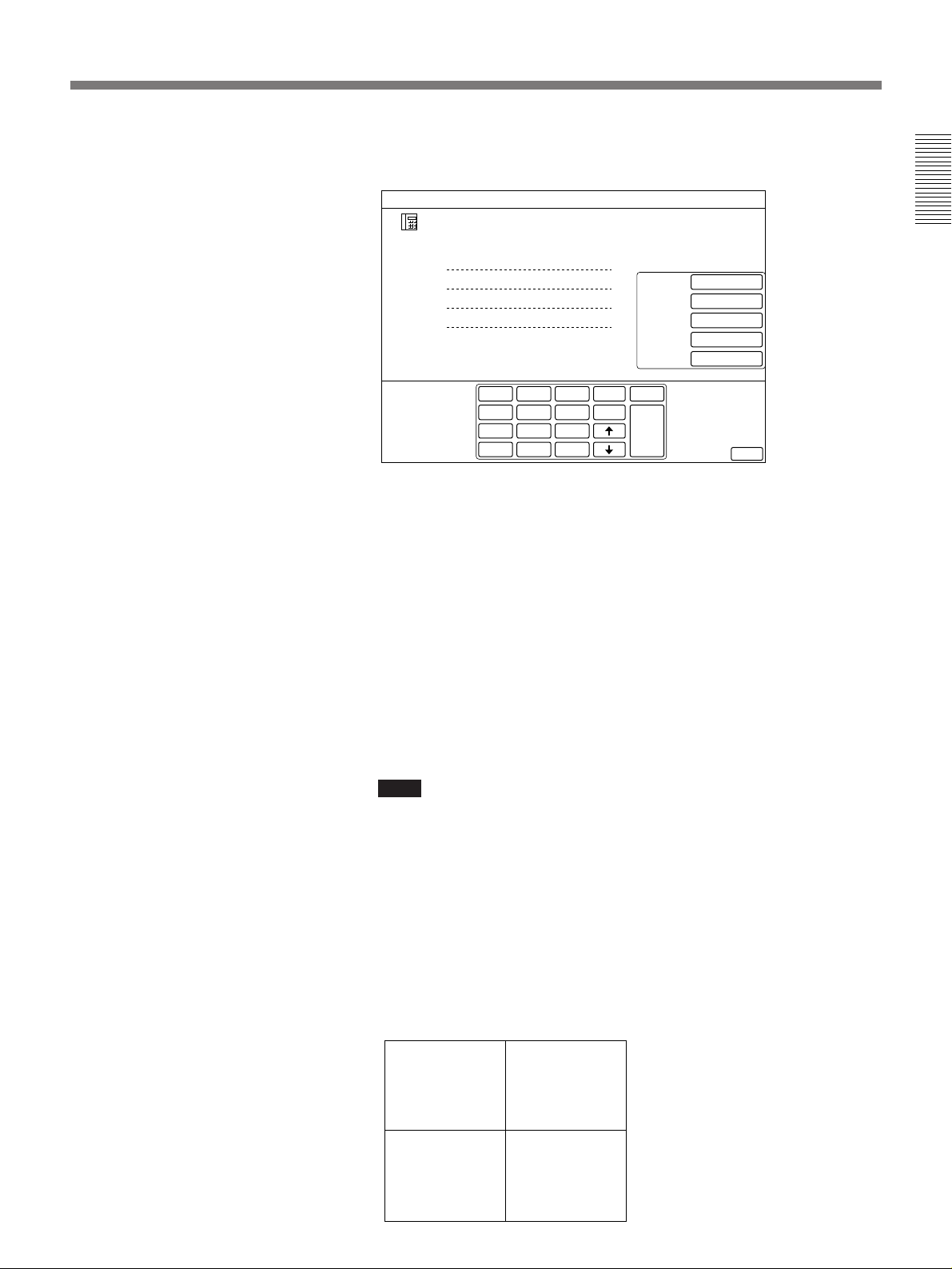
2 Select [MANUAL DIAL] from the OTHER sub-menu.
The MANUAL DIAL menu appears.
MANUAL DIAL
A1
A2
B1
B2
1
2
GHI
4
PQRS
7
∗
3
ABC
DEF
JKL
MNO
5
6
TUV
WXYZ
8
9
0
#
delete
copy
clear
DIAL
BRI
AUTO
7K
OFF
H.261
15FPS
LINE I/F
LINE RATE
AUDIO BAND
T.120/H.281
VIDEO MODE
EXIT
3 Enter the line number of the remote party.
Enter the line number of the remote party A on A1 line, of the party B
on A2 line. Use an asterisk (*) to add a sub address. Only numbers can
be used. (When you have not installed the optional PCS-I300 BRI
Board, you cannot enter the numbers on B1 and B2 lines.)
The way to use on-screen keyboards in the MANUAL DIAL menu is the same
as one in the DIAL LIST menu. For details, see “To use the on-screen
keyboard” on page 2-5.
4 Select [LINE I/F] to set the line interface to [BRI-M].
Chapter 1
5 Select [LINE RATE] to set the transfer rate and [AUDIO BAND] to
set the audio bandwidth.
For details on the line interface and transfer rate, see page 2-4.
Note
You cannot set [T.120/H.281] and [VIDEO MODE].
6 Select [DIAL].
The system starts dialing the selected party.
Once connection has been made with all parties, the TV monitor screen
splits into four sections to display the remote parties as well as your
own group. The MAIN menu appears and the remote parties can be
heard over the sound system.
The lines of each party are connected automatically (A connects with
B).
Once all connections have been made, you can start the meeting.
Party A
Party B
Local party
Chapter 1 Using the Basic System 1-23
Page 32
Holding a Meeting With Multiple Remote Parties
Changing the Picture Display Format
Select [MULTI] from the MAIN menu, then select as follows:
Chapter 1
AUTO: Displays the party currently speaking on a full screen.
MANUAL: Each time you select [MANUAL], the screen cycles between
party A and party B.
MULTI: Displays remote parties and your own group on a quadrant
screen.
Notes
•The inset window does not appear when it is in the multi meeting.
•When you have selected [AUTO] or [MANUAL], be aware that all the
remote parties may not be viewing the same screens.
Using Two ISDN Lines
When you install an optional PCS-I300 BRI Board into the Rollabout
Processor, you can use the dual ISDN lines during the meeting, which
expands the functions of the Rollabout Processor as follows.
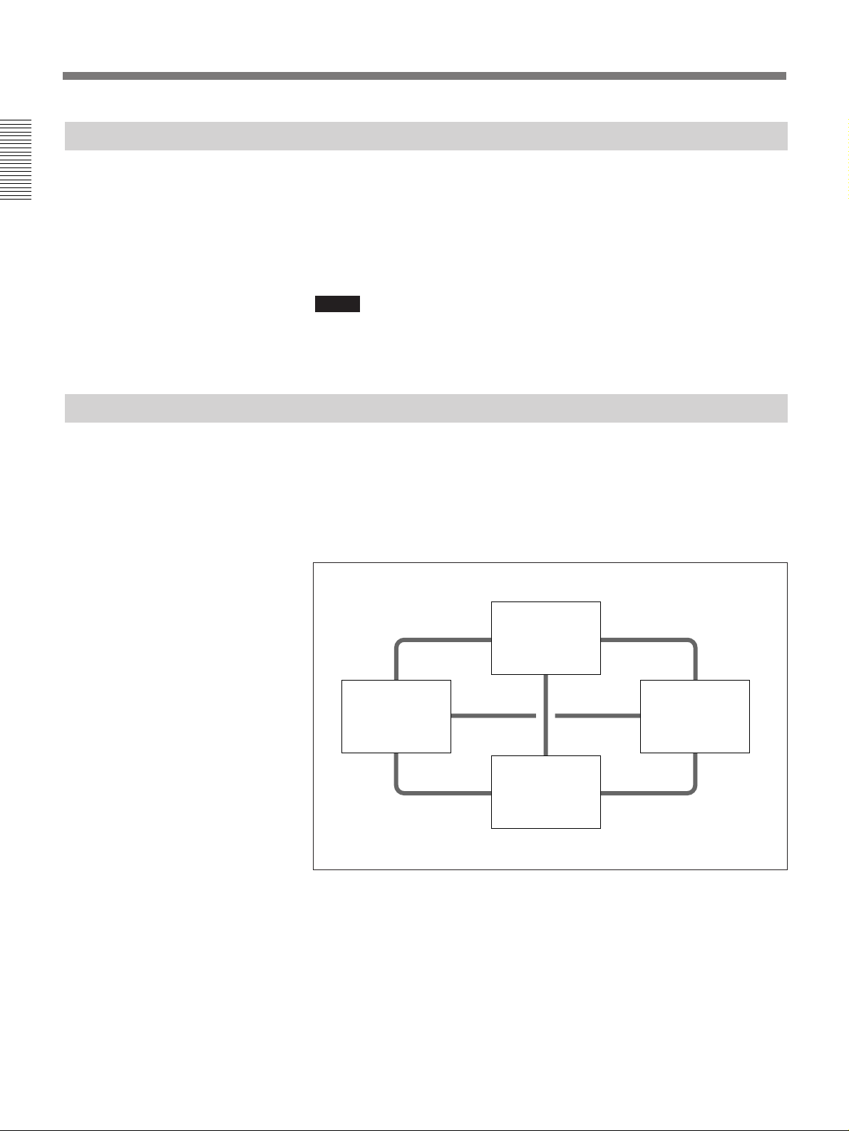
A meeting among four parties via dual ISDN lines
You can hold a multi meeting among four parties.
Local party
Party A
Party B
Party C
1-24 Chapter 1 Using the Basic System
Page 33
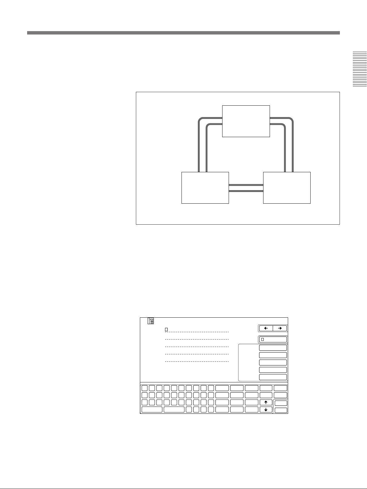
A meeting among three parties via dual ISDN lines
Dual ISDN lines among each parties make transfer rate faster than using
the single ISDN line, which promotes the clear sound and image
reproductions during the meeting.
Local party
Chapter 1
Party A
Party B
Notes on the registration in the DIAL SETUP menu
•When holding a meeting among four parties via dual ISDN lines, enter
the first remote party’s telephone number on the A1 entry line, the
second’s number on the A2 entry line, and the third’s number on the B1
entry line. In this case, telephone numbers for remote parties are the ones
connected to each party’s ISDN A jack.
•When holding a meeting among three parties via dual ISDN lines, enter
the first remote party’s telephone number on the A1 and A2 entry lines,
the second’s number on the B1 and B2 entry lines.
SETUP
001
LOCK
3
6
9
#
LINE I/F
LINE RATE
AUDIO BAND
T.120/H.281OFF
VIDEO MODE
delete
copy
clear
kana
DIAL
EXIT
BRI
AUTO
3.4K
H.261
15FPS
2
5
8
0
Q
A
Z
capslock
INDEX
A 1
A 2
B 1
B 2
W
S
X
E
R
T
Y
U
I
O
P
1
D
F
G
H
J
K
L
&
4
C
V
B
N
M
.
space
,
–
7
:
”
(
)
x
–
Chapter 1 Using the Basic System 1-25
Page 34
Holding a Meeting With Multiple Remote Parties
Ending the Multi Meeting
There are two ways to end a meeting. It depends on your position of a
meeting.
Chapter 1
When you have participated in a multi meeting:
Select [HANG UP] from the MAIN menu, only you can end a multi
meeting. Other parties can continue their meeting.
When you have held a multi meeting:
Select [HANG UP ALL] from the MAIN menu, the multi meeting ends
completely.
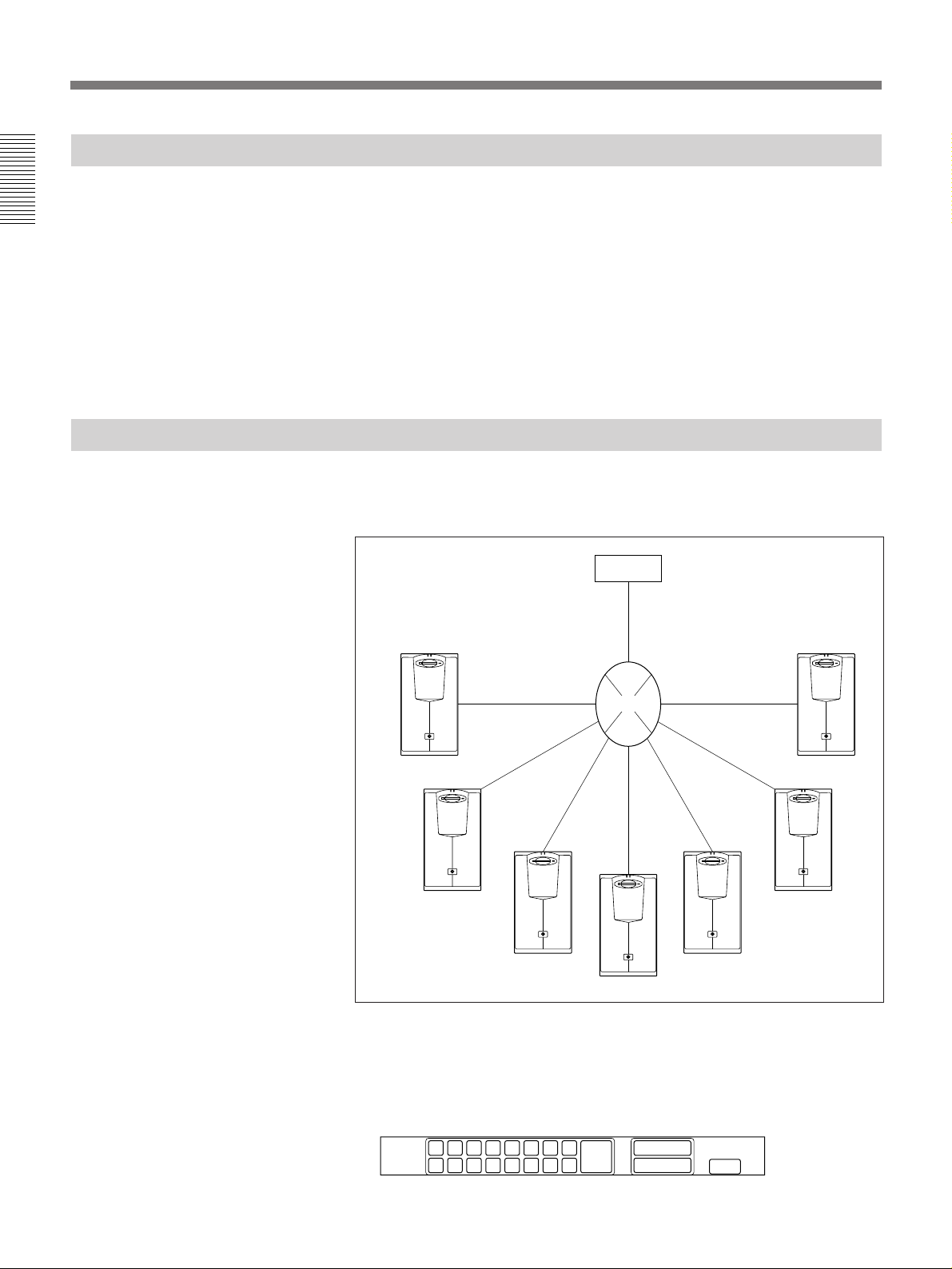
Connecting With MCU to Perform the Chairman Control
You can perform multiple communication between 16 terminals with
making a connection to MCU (Multipoint Control Unit).
1
Terminal
6
2
MCU
Terminal
BUSY
6
BUSY
ISDN
!§
6
BUSY
6
BUSY
6
BUSY
6
BUSY
3
!¢
6
BUSY
!∞
4........!£
1-26 Chapter 1 Using the Basic System
1 Connect to the MCU.
2 Select [MULTI] from the MAIN menu.
The MCU menu appears.
192103114125136147158
NEAR
END
16
•1 to !§ means the numbers of connected terminal.
RECEIVE
BROADCAST
MCU
EXIT
Page 35

To see the picture of the selected terminal
Select [RECEIVE] and then select the terminal number you want to see.
The picture of the selected terminal appears on your monitor.
To send the picture of the selected terminal to all the terminals
Select [BROADCAST] and then select the terminal number you want to
see.
The picture of the selected terminal appears on your monitor and it is sent
to all the terminals.
To send the picture of your terminal to all the terminals
Select [BROADCAST] and then select [NEAR END].
The picture of your terminal is send to all the terminals.
Note
The specifications of the MCU may be different depending on the type of
the MCU you connect.
Chapter 1
Chapter 1 Using the Basic System 1-27
Page 36

Page 37
Registering a Remote Party
You need to register a remote party before you connect with the party.
Registration involves entering the name and telephone numbers of the
remote party.
You can register up to 120 remote parties.
You can register the most frequently used numbers in the QUICK DIAL
menu (#1 to #10) for quick and easy dialing. (Once you sort the DIAL
LIST, the order of the registered index numbers are changed.)
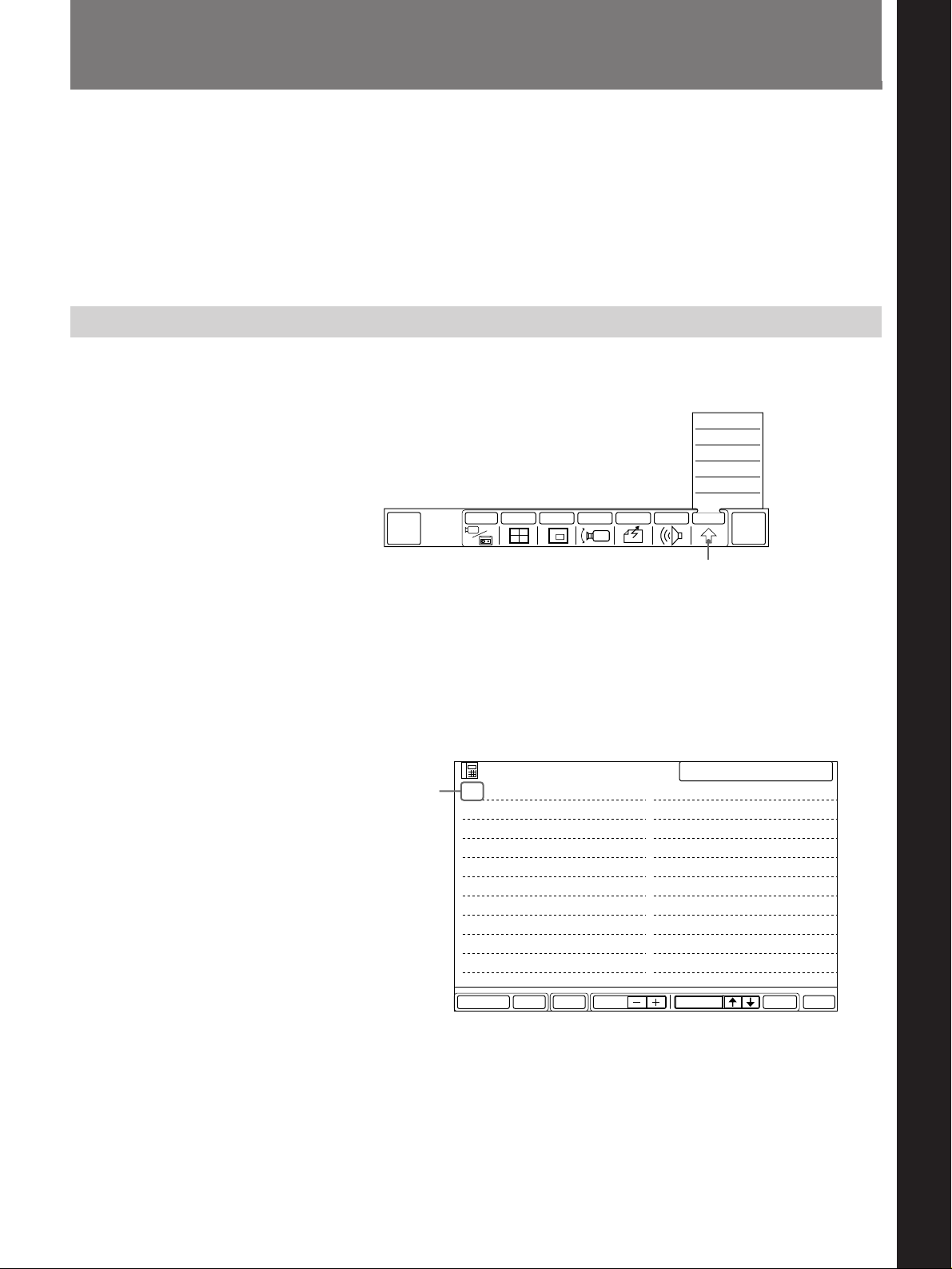
Making an Entry
1 Select [OTHER] from the MAIN menu.
The OTHER sub-menu appears.
QUICK
DIAL
INPUT MULTI P in P CAMERA SEND AUDIO OTHER
SETUP
STATUS
DTMF
T.120
DIAL LIST
MANUAL DIAL
END OF
MEETING
Chapter 2 Settings
Chapter 2
[OTHER]
2 Select [DIAL LIST] from the OTHER sub-menu.
The DIAL LIST menu appears.
3 Select an index number by using [>] or [.].
If some of the numbers already have used, select an empty index
number.
The color of the selected index number changes to blue.
Selected
index
number
LIST
001
002
003
004
005
006
007
008
009
010
SETUPDELETE PAGE EXITDIALSELECTMULTI
SELECTED 001
011
012
013
014
015
016
017
018
019
020
• If more than 20 numbers have already been registered (if the page is
full), go to the next DIAL LIST page.
• Select [PAGE +] to move to the next DIAL LIST page.
• Select [PAGE –] to move to the previous DIAL LIST page.
(Continued)
Chapter 2 Settings 2-1
Page 38
Menus
Registering a Remote Party
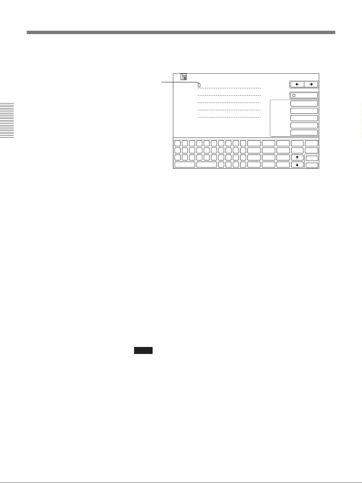
4 Select [SETUP].
The DIAL SETUP menu appears.
Chapter 2
Q
A
Z
capslock
INDEX
A 1
A 2
B 1
B 2
W
S
X
SETUP
E
D
C
001
LOCK
3
6
9
#
LINE I/F
LINE RATE
AUDIO BAND
T.120/H.281OFF
VIDEO MODE
delete
copy
BRI
AUTO
3.4K
H.261
15FPS
R
T
Y
U
I
O
P
1
2
F
G
H
J
K
L
&
4
5
7
V
B
N
M
.
:
”
space
,
–
(
)
8
x
0
–
Block
cursor
5 Enter the name for remote party in the line following INDEX.
Use the on-screen keyboard to enter the names and numbers.
For entering a name using the on-screen keyboard, see page 2-5.
6 After entering a name, select [.] from the on-screen keyboard.
The block cursor moves to the A1 entry line.
7 Enter the telephone number of the remote party.
If the remote party has more than one telephone number, enter the first
number and select [.] from the on-screen keyboard, then enter the
second number on the next line. (When you have not installed the
optional PCS-I300 BRI Board, you cannot enter the numbers on B1
and B2 lines.)
You can use the [copy] key to copy the number on the line above onto
the current line.
For details on the [copy] key, see page 2-6.
clear
kana
DIAL
EXIT
2-2 Chapter 2 Settings
Note on the optional PCS-I300 BRI Board
If you install the optional PCS-I300 BRI Board (see page 4-13), you
can use two ISDN lines (up to 4B). In this case, enter second telephone
number on B1 and B2 entry lines.
Notes
•If the ISDN line system in your country designates one number per line,
conduct the following:
For an ISDN line at a 2B (1B is 56/64 Kbps) transfer rate, enter the same
number on two consecutive lines. When you install the optional PCSI300 BRI Board for a 4B transfer rate, enter the two numbers (the same
number for each) on two consecutive lines. (The faster the transfer rate,
the smoother motions will appear on the TV monitor.)
Use a comma (,) or an asterisk (*) to add a sub address. Only numbers
can be used.
•If the remote party uses a PCS-2000 series system and local party uses
two ISDN lines, enter the remote party’s telephone numbers in the order
they are connected to the ISDN A and B jacks.
•If you are using the ISDN line and calling a party in the USA from
outside the USA, set [LINE RATE] to [56K].
For details on line rate settings, see page 2-4.
Page 39
To connect via the V.35 interface
If the optional PCS-I500 V.35 line interface board is installed and connect
to private line or a terminal adapter via the V.35 interface, select [V.35] in
[LINE I/F] and enter as follows.
The example below uses Channel A only. If you use Channel A and B (56
Kbps × 2 or 64 Kbps × 2), enter “V” for both A1 and A2.
INDEX
A 1 V
---------------------------------------------
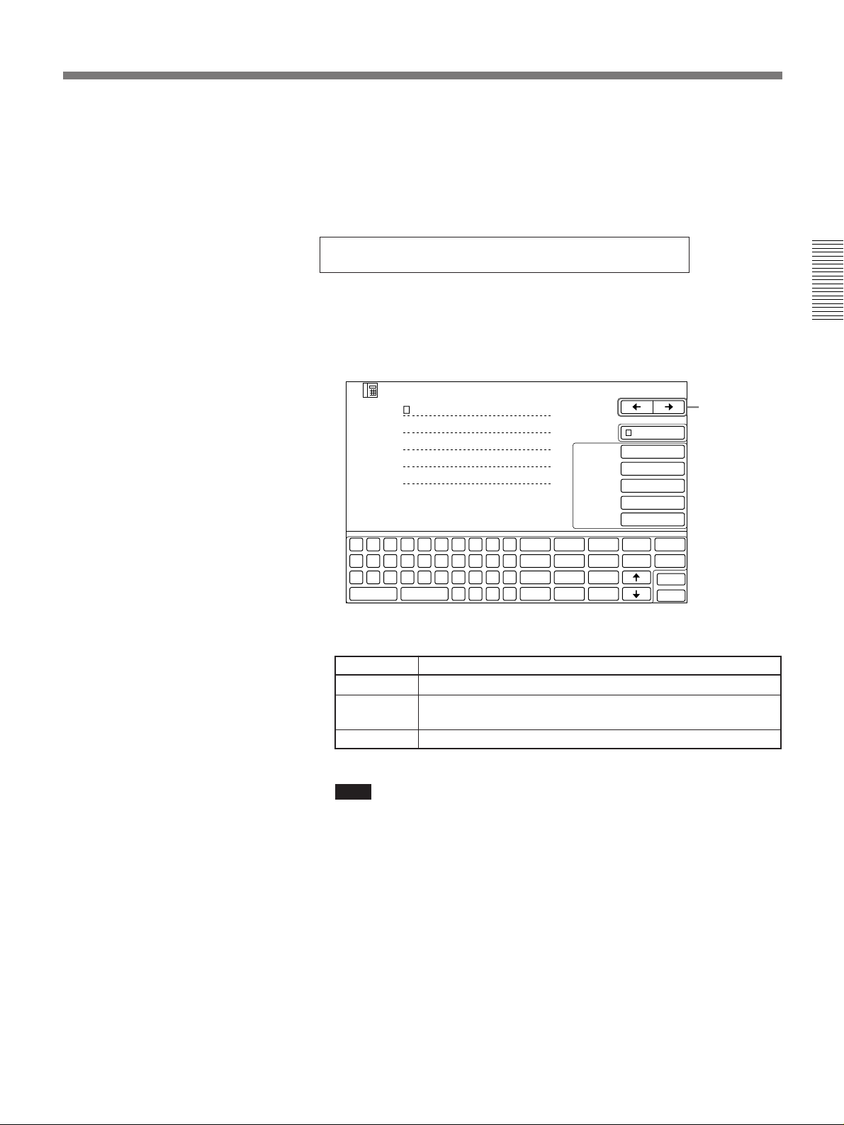
8 To make more remote party name and number entries, select [/] at
the upper-right corner on the DIAL SETUP menu.
Repeat steps 5 to 7 to register additional remote parties. (To return to
the previous entry, select [?].)
SETUP
[?], [/]
clear
kana
DIAL
EXIT
Q
A
Z
capslock
INDEX
A 1
A 2
B 1
B 2
W
S
X
001
LOCK
3
6
9
#
LINE I/F
LINE RATE
AUDIO BAND
T.120/H.281OFF
VIDEO MODE
delete
copy
BRI
AUTO
3.4K
H.261
15FPS
E
R
T
Y
U
I
O
P
1
2
D
F
G
H
J
K
L
&
4
5
7
C
V
B
N
M
.
:
”
space
,
–
(
)
8
x
0
–
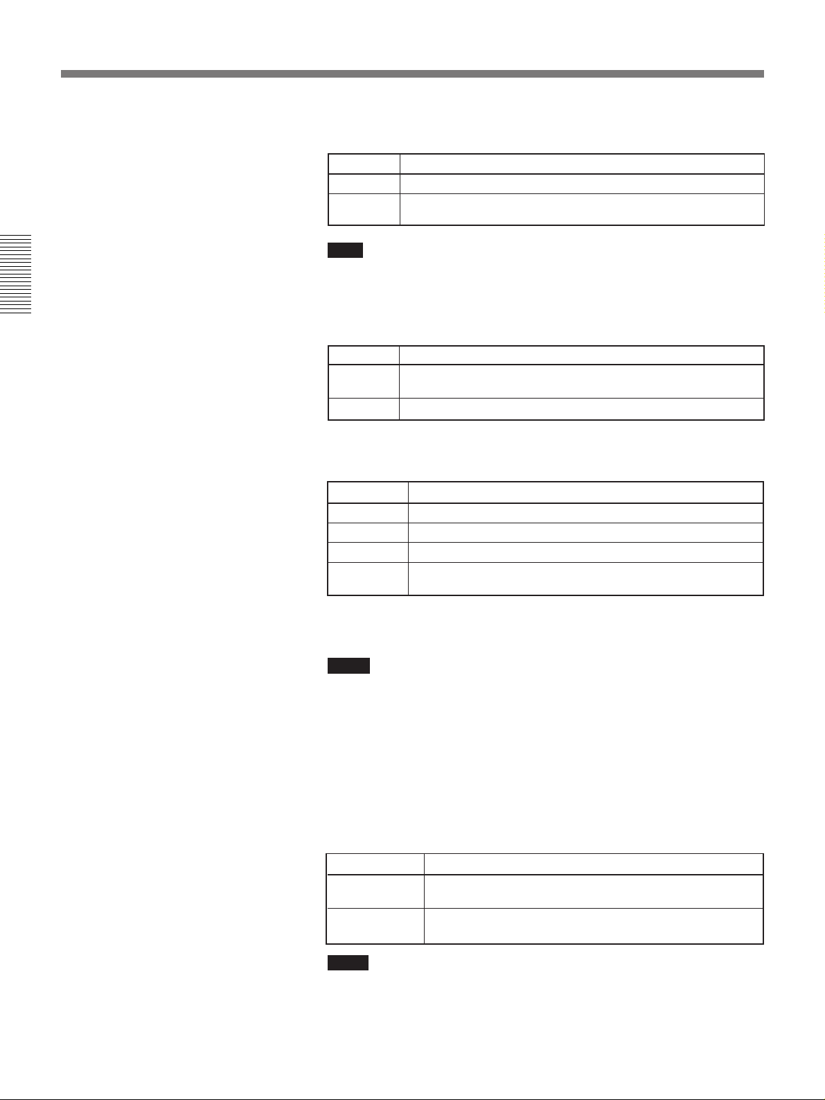
9 Select [LINE I/F] to set the line interface.
Chapter 2
Setting Description
BRI To connect to one remote party via a normal ISDN line.
BRI-M To connect to more than two remote party with a normal ISDN
line. (multi meeting)
V.35 To connect via the V.35 interface.
Note
If the desired line interface setting does not appear, the interface board
may have been installed incorrectly or may be broken.
(Continued)
Chapter 2 Settings 2-3
Page 40
Registering a Remote Party
10
Select [LINE RATE] to set the transfer rate.
Setting Description
AUTO To connect to a normal ISDN line.
56K To connect with a region or country with a 56 Kbps ISDN
transfer rate.
Note
If you are using the line interfaces other than ISDN, you do not need to
set the transfer rate.
Chapter 2
11
Select [AUDIO BAND] to set audio bandwidth.
Setting Description
3.4K The audio bandwidth is narrow but the image quality is better.
7K The audio bandwidth is wider for better sound quality. (G.722)
12
Select [T.120/H.281] to set the T.120 rate or the remote camera control
(G.728)
form based on H.281 standards.
Setting Description
OFF When not using both T.120 and H.281.
T.120 9.6K When holding a T.120 data meeting and [AUDIO] is set to 7K.
T.120 38.4K
H.281 When selecting the remote camera control form based on
When holding a T.120 data meeting and [AUDIO] is set to 3.4K.
H.281 standards.
When having a T.120 data meeting, we recommend you to set
[AUDIO BAND] to 3.4K, and [T.120/H.281] to T.120 38.4K.
Notes
• You cannot select the remote camera control form based on H.281
standards when you hold a T.120 data meeting, and vice versa.
• When [LINE I/F] is set to BRI-M, [T.120/H.281] and [VIDEO
MODE] cannot be set.
• When [AUDIO BAND] is set to 7K, you cannot select T.120 38.4K.
• When having a T.120 data meeting or select H.281, you cannot
perform the multi meeting function and remote party’s camera
control, sending and receiving still pictures.
2-4 Chapter 2 Settings
13
Select [VIDEO MODE] to set the video format.
Setting Description
H.261 15FPS Send a picture based on H.261 at a maximum rate of 15
H.263 15FPS Send a picture based on H.263 at a maximum rate of 15
Notes
frames per second.
frames per second.
•When [LINE I/F] is set to BRI-M, the video format cannot be set. The
video format is automatically set to H.261 15FPS.
•When [VIDEO MODE] is set to H.263 15FPS, you only call remote
parties which are registered on A1 and A2 lines.
•When [VIDEO MODE] is set to H.263 15FPS, the transfer rate is
automatically set to 56 –128 kbps.
Page 41
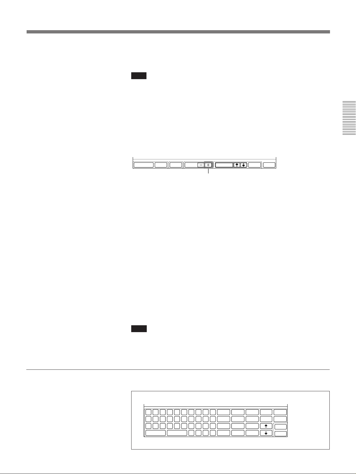
•When [VIDEO MODE] is set to H.263 15FPS, you cannot send/
receive still pictures.
Note
The settings in steps 9 to 13 are for making a call to a remote party.
After registering the names and numbers, select [EXIT].
The entries are registered. If you select [DIAL] here instead of [EXIT],
you will be able to hold a meeting, but the entries will not be registered. To
register the entries, select [EXIT] from the DIAL SETUP menu during or
after a meeting.
If the DIAL LIST page is full, select [PAGE +] in step 3 (page 2-1).
The next DIAL LIST page is displayed.
SETUPDELETE PAGE EXITDIALSELECTMULTI
[PAGE +]
To return to the previous DIAL LIST page, select [PAGE –].
There are six DIAL LIST pages; you can register up to 20 remote parties
on one DIAL LIST page.
To lock a registration
Select [LOCK] from the DIAL SETUP menu to lock the setting. The color
of the check box changes to blue.
To unlock the setting, select [LOCK] again. The color of the check box
returns to the original color.
Chapter 2
To use the on-screen keyboard
To change the ISDN transfer rate temporarily
The PCS-3000/3000P Rollabout Package is set to 64 Kbps for an ISDN
line at the factory. However, some countries (e.g., USA) and regions may
have 64 Kbps and 56 Kbps ISDN transfer rates. If the remote party has set
its transfer rate to 56 Kbps, you need to set your system to 56 Kbps to
communicate with that system.
Before making a call to such a party, change the transfer rate to 56 Kbps in
[LINE RATE] in the DIAL SETUP menu.
Note
If the transfer rate at the remote Rollabout Processor is set to 56 Kbps, the
connection will be made at 56 Kbps even if your transfer rate has been set
to [AUTO].
Q
W
E
R
T
Y
U
I
O
P
1
2
A
Z
capslock
3
S
D
F
G
H
J
K
L
&
4
5
6
7
8
X
C
V
B
N
M
.
:
”
space
,
––
(
)
–x
9
0
#
delete
copy
clear
kana
DIAL
EXIT
Alphabet
input mode
On-screen keyboard
Chapter 2 Settings 2-5
Page 42

Registering a Remote Party
Chapter 2
To enter a character and digit
Press the cursor button (Z, 4, z, $) on the Remote Commander to move
the cursor to the desired character or digit, then press the execute button.
Note
The keyboard can be switched to either English or Kana (Japanese
Character) input mode.
If you accidentally activate the kana input mode, select [alphabet]. The
keyboard will then go into the alphabet input mode.
To enter capital letters
Select [capslock]. All input letters are capitalized until you select
[capslock] again. The color of [capslock] changes to blue when the caps
lock is activated.
To copy the number in the line above
Select [copy]. The number in the line above is copied to the line which the
block cursor is appeared.
To confirm telephone numbers
To delete a character
Select [delete]. The last entered character is deleted.
To move to another line
Select [.] or [>]. The block cursor moves to that line.
To delete all characters from a line
Move the block cursor to the line where you want to delete and select
[clear].
To move to other entries
Select [?] or [/] at the upper-right corner on the DIAL LIST menu.
The QUICK DIAL and DIAL LIST menus show only the names of the
registered remote parties.
If you need to check the telephone numbers of the registered remote
parties, select [REGISTER] from the DIAL LIST menu.
To list the registered remote parties
If the list of the registered remote parties is not displayed, select [OTHER]
from the MAIN menu. The OTHER sub-menu appears.
Select [DIAL LIST]. The DIAL LIST menu appears.
To move to the next DIAL LIST page, select [PAGE +].
To move to the previous DIAL LIST page, select [PAGE –].
To finish, select [EXIT].
2-6 Chapter 2 Settings
Page 43
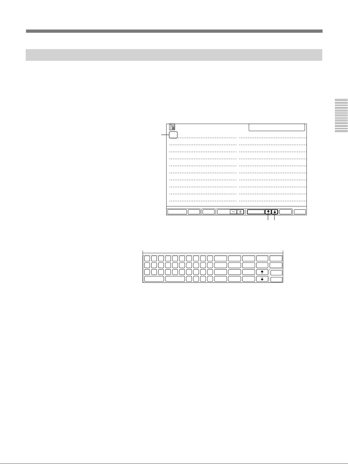
Modifying an Entry
You can modify the name and telephone numbers of an entry.
If the entry is locked (the check box [LOCK] is blue), you cannot modify the entry.
For details, see page 2-5.
1 Select an index number to modify in the DIAL LIST menu by using
[>] or [.].
The selected index number changes to blue.
Selected
index
number
LIST
001 Boston branch
002 Montreal branch
003 Chicago branch
004 Seattle branch
005 Buffalo branch
006 Detroit branch
007 San Francisco branch
008 Miami branch
009 Toronto branch
010 Ottawa branch
SETUPDELETE PAGE EXITDIALSELECTMULTI
SELECTED 001
011 Dallas branch
012 Los Angeles branch
013 San Diego branch
014 New Orleans branch
015 Cleveland branch
016 Pittsburgh branch
017 Philadelphia branch
018 Atlanta branch
019 Denver branch
020 Memphis branch
[>], [.]
2 Select [SETUP].
The on-screen keyboard appears.
Q
W
E
R
T
Y
U
I
O
P
1
2
A
Z
capslock
3
S
D
F
G
H
J
K
L
&
4
5
6
7
8
X
C
V
B
N
M
.
:
”
space
,
––
(
)
–x
9
0
#
delete
copy
clear
kana
DIAL
EXIT
3 Use the on-screen keyboard to modify the entry.
To move to another entry, select [?] or [/] at the upper-right corner
on the DIAL LIST menu.
Chapter 2
4 Select [EXIT].
The entry is modified.
Chapter 2 Settings 2-7
Page 44

Registering a Remote Party
Deleting an Entry
You can delete a registered entry as follows.
If the entry is locked (the check box [LOCK] is blue), you cannot delete the entry.
For details, see page 2-5.
1 Select an index number to delete in the DIAL LIST menu by using
[>] or [.].
The selected index number changes to blue.
Chapter 2
Remote
party to
be
deleted
LIST
001 Boston branch
002 Montreal branch
003 Chicago branch
004 Seattle branch
005 Buffalo branch
006 Detroit branch
007 San Francisco branch
008 Miami branch
009 Toronto branch
010 Ottawa branch
SETUPDELETE PAGE EXITDIALSELECTMULTI
SELECTED 001
011 Dallas branch
012 Los Angeles branch
013 San Diego branch
014 New Orleans branch
015 Cleveland branch
016 Pittsburgh branch
017 Philadelphia branch
018 Atlanta branch
019 Denver branch
020 Memphis branch
[>], [.]
2 Select [DELETE].
The following confirmation menu appears.
OK
DELETE
3 Select [OK] to delete the entry you selected in step 1.
2-8 Chapter 2 Settings
To cancel the operation, select [DELETE] again.
Page 45
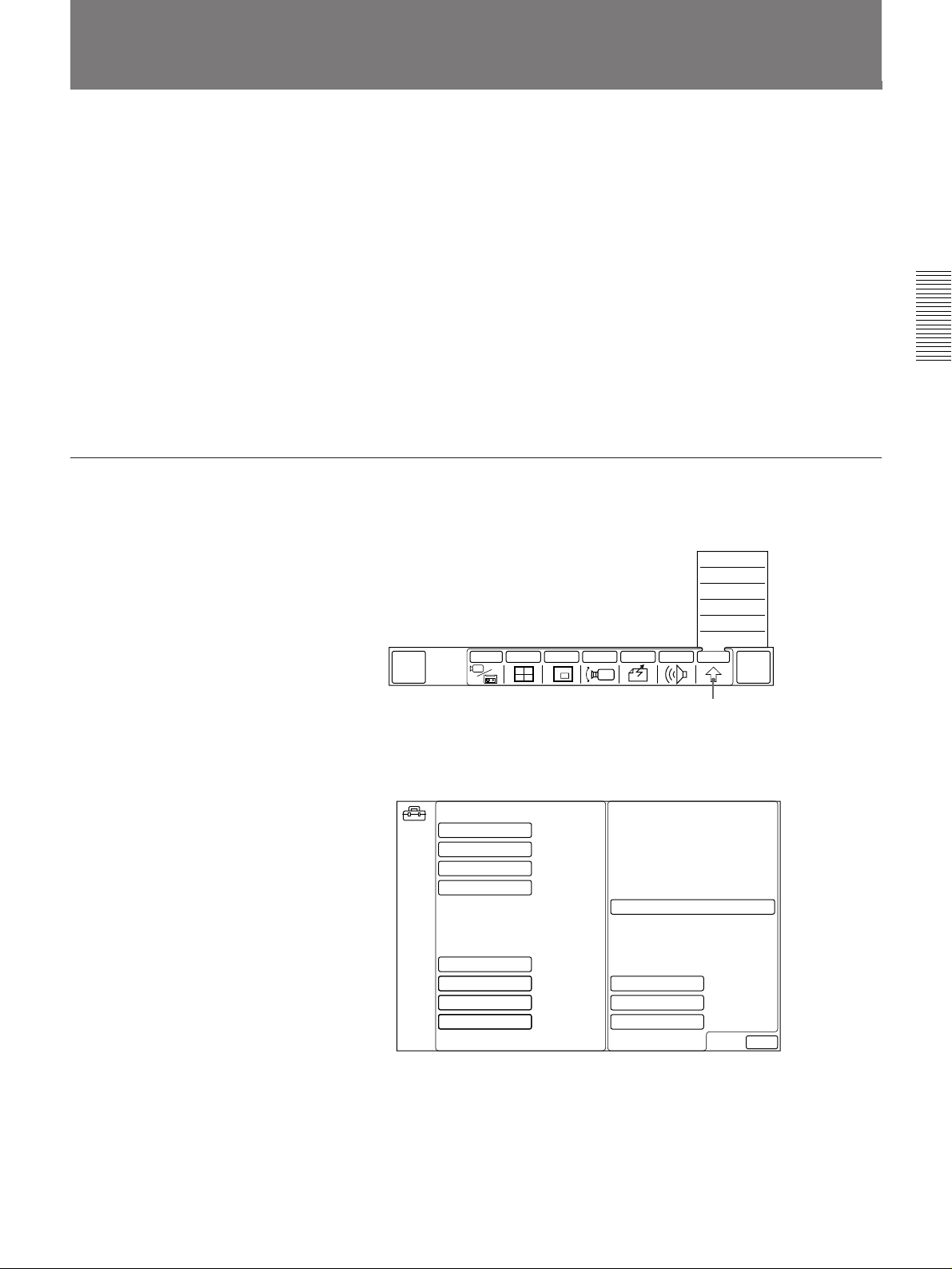
Setting the Answer Mode
The answer mode setting determines how the system responds to incoming
calls. It can be set to one of the following:
•AUTO
Your system receives the call and starts the system automatically. Your
party will be displayed on the remote party’s monitor.
•MANUAL
Incoming calls are not connected. You must manually connect the call
before it appears on screen.
This is useful in situations when you are not ready to start the meeting.
The factory setting is AUTO. To change the answer mode setting, follow
the steps below.
To change the answer mode to manual
1 Select [OTHER] from the MAIN menu.
The OTHER sub-menu appears.
QUICK
DIAL
SETUP
STATUS
DTMF
T.120
DIAL LIST
MANUAL DIAL
INPUT MULTI P in P CAMERA SEND AUDIO OTHER
END OF
MEETING
Chapter 2
2 Select [SETUP].
The SETUP menu appears.
SETUP
ANSWER MODE
BRI RATE
V.35 PORT
T.120/H.281
FAR END CTRL
LIP SYNCH OFF
SIRCS OUTPUT
LANGUAGE
AUTO
AUTO
SINGLE
OFF
ON
1
ENGLISH
[OTHER]
SORT DIAL LIST
CAM BRIGHT
PERIPHERAL
LDN
EXIT
(Continued)
Chapter 2 Settings 2-9
Page 46

Setting the Answer Mode
Chapter 2
3 Set the answer mode you want from [ANSWER MODE].
Each time you select [ANSWER MODE], the answer mode switches
between AUTO and MANUAL.
Note
Do not change any other settings.
4 Select [EXIT].
The setting selected in step 3 becomes active, and the MAIN menu
appears.
2-10 Chapter 2 Settings
Page 47
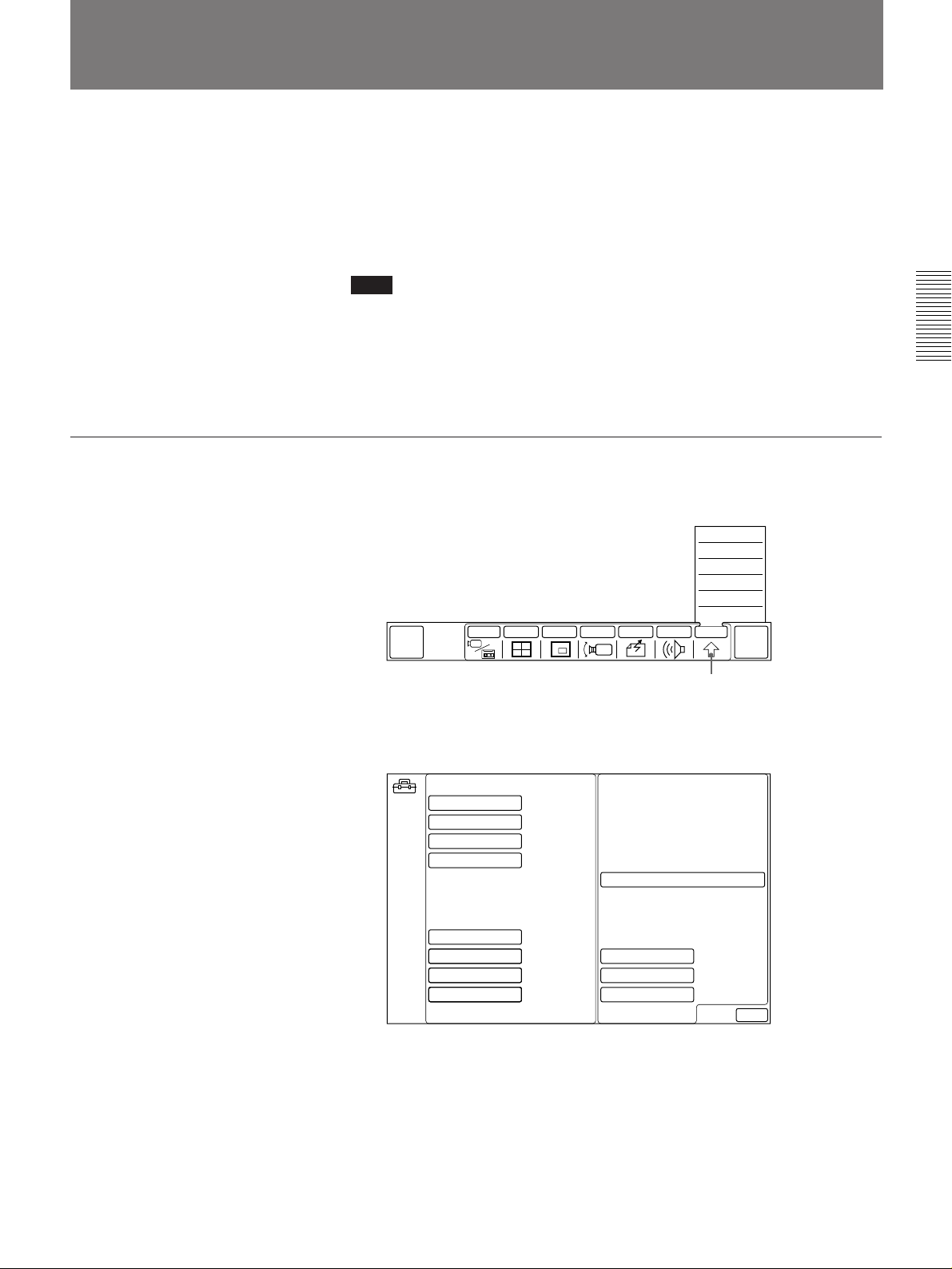
Synchronizing Voice and Motion (Lip Synchronization)
During a meeting, voice and motion may not become synchronized.
The automatic lip synchronization function built into the system solves this
problem by closely synchronizing audio and video before they are
transmitted to the remote party.
The lip synchronization function is set to OFF at the factory.
Note
The lip synchronization function only works for your own party. To
activate the lip synchronization function on a remote party, you must ask
them to do so.
To change the lip synchronization setting, follow the steps below.
To set lip synchronization
1 Select [OTHER] from the MAIN menu.
The OTHER sub-menu appears.
SETUP
STATUS
DTMF
T.120
DIAL LIST
MANUAL DIAL
QUICK
DIAL
INPUT MULTI P in P CAMERA SEND AUDIO OTHER
END OF
MEETING
Chapter 2
2 Select [SETUP].
The SETUP menu appears.
SETUP
ANSWER MODE
BRI RATE
V.35 PORT
T.120/H.281
FAR END CTRL
LIP SYNCH OFF
SIRCS OUTPUT
LANGUAGE
AUTO
AUTO
SINGLE
OFF
ON
1
ENGLISH
[OTHER]
SORT DIAL LIST
CAM BRIGHT
PERIPHERAL
LDN
EXIT
(Continued)
Chapter 2 Settings 2-11
Page 48
Synchronizing Voice and Motion (Lip Synchronization)
3 Select ON, OFF or AUTO in [LIP SYNCH].
Setting Select
Lip synchronization function is activated. ON
Lip synchronization function is deactivated. OFF
Lip synchronization function is activate with zoom-in; AUTO
deactivated with zoom-out.
Note
Chapter 2
Do not change any other settings.
4 Select [EXIT].
The new setting selected in step 3 becomes active, and the MAIN
menu appears.
2-12 Chapter 2 Settings
Page 49
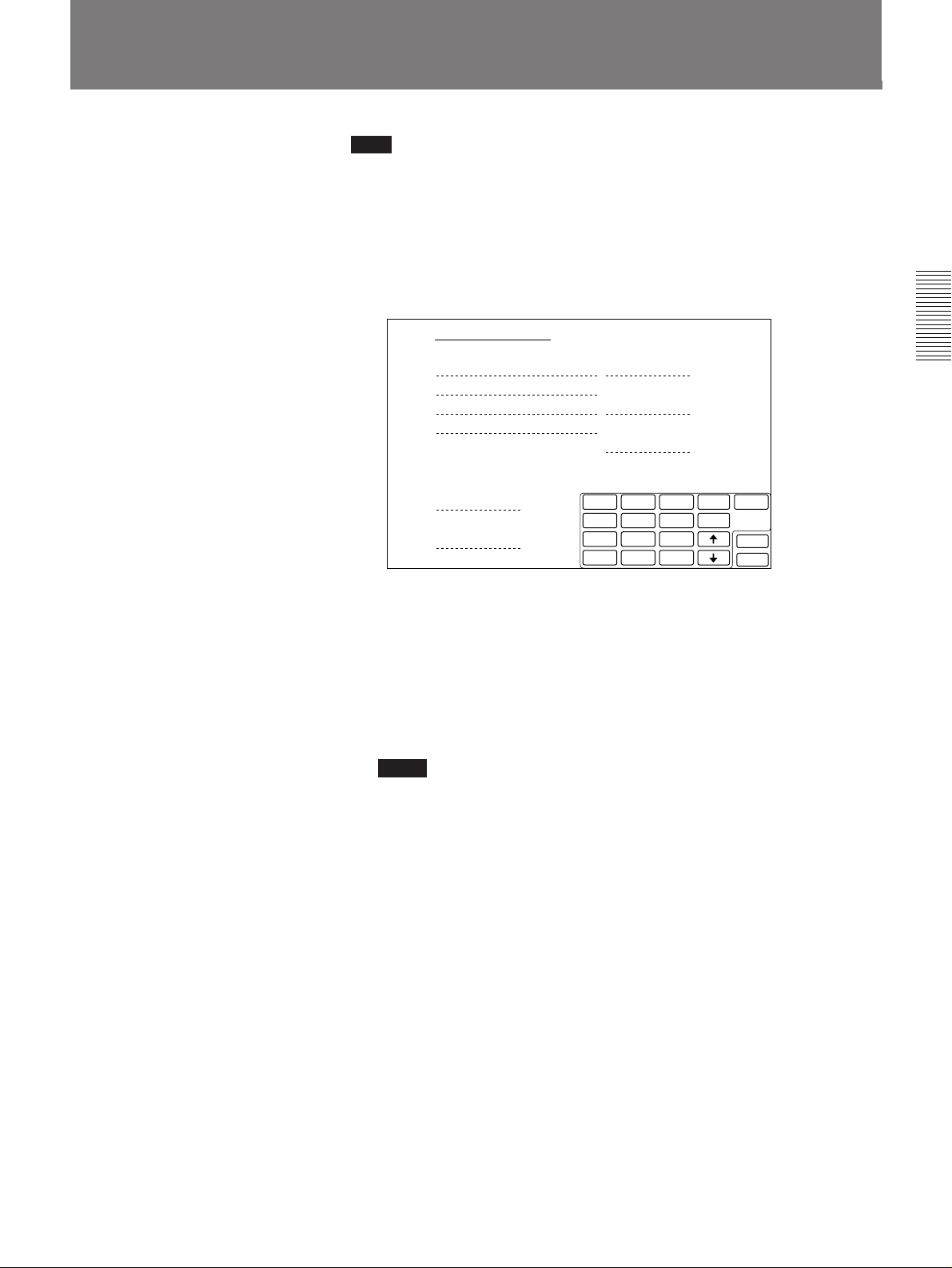
Registering Sub Addresses and Local System Data
Note
You always need to register the LOCAL NUMBER (LN) and COUNTRY
CODE (CC) when you use this system.
You have to register required information about your own system.
1 Select [LDN] from the SETUP menu.
The LDN menu appears.
LOCAL DIRECTORY NUMBER
LOCAL NUMBER (LN)
A 1
A 2
B 1
B 2
LOCAL CALL
+LN
LONG DISTANCE CALL
+AC+LN
INTERNATIONAL CALL
+CC+AC+LN
Chapter 2
COUNTRY CODE (CC)
AREA CODE (AC)
1
2
3
4
5
6
7
8
9
0
–
x
–
cleardelete
copy
SPID
EXIT
2 Enter your telephone number and sub address in the LOCAL
NUMBER (LN) section.
Enter the telephone number connected to the ISDN A jack at the rear
of the Rollabout Processor in the lines headed A1 and A2.
If you installed the optional PCS-I300 BRI Board into the Rollabout
Processor, enter the telephone number connected to the ISDN B jack in
the lines headed B1 and B2 also.
Notes
• When using a dial-in service, enter hyphen (–) at the end of the line
numbers entered on A1 line.
• Always place a hyphen (–) between the local switch number and the
subscriber number.
• When setting a sub address, always follow the telephone number
with an asterisk.
3 Enter your country code on the line headed COUNTRY CODE (CC)
(e.g., enter “1” for the US.)
4 Enter your area code on the line headed AREA CODE (AC).
Be careful not to enter the first zero (e.g., enter only “408” for
California).
5 If you are using a private branch exchange (PBX), enter your outside
telephone number in line marked LOCAL CALL (e.g., enter “9” if you
have to dial nine to get an outside line).
(Continued)
Chapter 2 Settings 2-13
Page 50

Registering Sub Addresses and Local System Data
6 Enter the prefix number, of your area code, which you did not enter in
the step 4 above in the line headed by LONG DISTANCE CALL.
(e.g., for California, enter “0”.) When you have your outside line
number entered in the step 5, enter the number again before the prefix
of your area code. (e.g., if “9” is your outside line number and “0” is
the prefix of your area code, enter “90”.)
7 If you intend to make overseas calls, enter your country code, area
code, and local number in the line headed INTERNATIONAL CALL.
Enter the number of the international telephone company you intend to
Chapter 2
use. Also enter a nine if you have to dial nine to get an outside line.
2-14 Chapter 2 Settings
Page 51

SPID Registration for Customers in the USA
If the system is connected to a network switch of the following types, you
can use ISDN lines.
•Network switch type: AT&T 5ESS
•Network switch software version: 5E8 or later (for National ISDN-1 and
National ISDN-2)
or
•Network switch type: Northern Telecom (NTI) DMS-100
•Network switch software version: BCS34 or later (for National ISDN-1
and National ISDN-2)
If the system is connected to a network switch of the following types, you
can also use ISDN lines.
•Network switch type: AT&T 5ESS
•Network switch software version: 5E8 or later (for Multipoint or Pointto-Point Custom ISDN)
or
•Network switch type: Northern Telecom (NTI) DMS-100
•Network switch software version: BCS34 or later (for Custom ISDN)
Chapter 2
In these cases, you shall register the LDN (Local Directory Number:
seven-digit local phone number).
Follow the steps below to register the LDN(s).
1 On the SETUP menu, select LDN.
2 Use the on-screen keyboard to add the COUNTRY CODE.
If the network switch type is AT&T 5ESS (National ISDN)
COUNTRY CODE is 1
If the network switch type is NTI DMS-100 (National ISDN)
COUNTRY CODE is 1
If the network switch type is AT&T 5ESS (Multipoint Custom ISDN))
COUNTRY CODE is 1-10
If the network switch type is AT&T 5ESS (Point-to-Point Custom
ISDN)
COUNTRY CODE is 1-12
If the network switch type is NTI DMS-100 (Custom ISDN)
COUNTRY CODE is 1-11
3 Use the on-screen keyboard to add the LDNs.
If one ISDN line is used, register the LDN in entries A1 and A2
If two ISDN lines are used, register the LDNs in entries A1, A2, B1,
B2.
If the network switch type is AT&T 5ESS (National ISDN)
Each LDN is given for two channels (CH A1 and A2, CH B1 and B2)
or
Each LDN is different as a separate LDN is given for each channel.
(Continued)
Chapter 2 Settings 2-15
Page 52
SPID Registration for Customers in the USA
The following shows the use of two ISDN lines for AT&T 5ESS
(National ISDN).
In case of each LDN is given for two channels.
LN A1 9876532 LOCAL CALL
Chapter 2
In case of each LDN is different as a separate LDN is given for
each channel.
LN A1 9876543 LOCAL CALL
A2 9876532 9+LN
B1 9871356 LONG DISTANCE
B2 9871356 91+AC+LN
INTERNATIONAL
9011+CC+AC+LN
CC 1
AC 408
A2 9876544 9+LN
B1 9871234 LONG DISTANCE
B2 9871235 91+AC+LN
INTERNATIONAL
9011+CC+AC+LN
CC 1
AC 408
If the network switch type is AT&T 5ESS (Multipoint or Point-to-Point
Custom ISDN)
Each LDN is given for two channels (CH A1 and A2, CH B1 and B2,
CH C1 and C2).
The following shows the use of two ISDN lines for AT&T 5ESS
(Multipoint Custom ISDN).
LN A1 9876532 LOCAL CALL
A2 9876532 9+LN
B1 9871356 LONG DISTANCE
B2 9871356 91+AC+LN
CC 1-10
AC 408
INTERNATIONAL
9011+CC+AC+LN
The following shows the use of two ISDN lines for AT&T 5ESS
(Point-to-Point Custom ISDN).
LN A1 9876532 LOCAL CALL
A2 9876532 9+LN
B1 9871356 LONG DISTANCE
B2 9871356 91+AC+LN
CC 1-12
AC 408
INTERNATIONAL
9011+CC+AC+LN
2-16 Chapter 2 Settings
Page 53
If the network switch type is NTI DMS-100 (National ISDN or Custom
ISDN)
Each LDN is different as a separate LDN is given for each channel.
The following shows the use of two ISDN lines for NTI DMS-100
(National ISDN).
LN A1 9876543 LOCAL CALL
A2 9876544 9+LN
B1 9871234 LONG DISTANCE
B2 9871235 91+AC+LN
INTERNATIONAL
9011+CC+AC+LN
CC 1
AC 408
The following shows the use of two ISDN lines for NTI DMS100 (Custom ISDN).
LN A1 9876543 LOCAL CALL
A2 9876544 9+LN
B1 9871234 LONG DISTANCE
B2 9871235 91+AC+LN
INTERNATIONAL
9011+CC+AC+LN
CC 1-11
AC 408
Chapter 2
4 Select [SPID] to setup SPIDs.
SPID in the SPID menu and LN LIST in the LDN menu are entered in
pairs and should not be crossed with BRI channels as each has its own
LN.
Be sure to enter each number in pairs. If it is crossed, you must correct
the SPID-LN pairs.
If the network switch type is AT&T 5ESS (National ISDN)
The following shows the use of two ISDN lines.
In case of each LDN is given for two channels.
SPID
A1 019876532001
A2
B1 019871356001
B2
SPID in the SPID menu
LN A1 9876532 LOCAL CALL
A2 9876532 9+LN
B1 9871356 LONG DISTANCE
B2 9871356 91+AC+LN
INTERNATIONAL
9011+CC+AC+LN
CC 1
AC 408
LN in the LDN menu
(Continued)
Chapter 2 Settings 2-17
Page 54
SPID Registration for Customers in the USA
In case of each LDN is different as a separate LDN is given for
each channel.
Chapter 2
SPID
A1 019876543001
A2 019876544001
B1 019871234001
B2 019871235001
SPID in the SPID menu
LN A1 9876543 LOCAL CALL
A2 9876544 9+LN
B1 9871234 LONG DISTANCE
B2 9871235 91+AC+LN
INTERNATIONAL
9011+CC+AC+LN
CC 1
AC 408
LN in the LDN menu
If the network switch type is AT&T 5ESS (Multipoint Custom ISDN)
The following shows the use of two ISDN lines.
SPID
A1 019876532001
A2
B1 019871356001
B2
SPID in the SPID menu LN in the LDN menu
LN A1 9876532 LOCAL CALL
A2 9876532 9+LN
B1 9871356 LONG DISTANCE
B2 9871356 91+AC+LN
INTERNATIONAL
9011+CC+AC+LN
CC 1-10
AC 408
If the network switch type is AT&T 5ESS (Point-to-Point Custom
ISDN)
You don’t have to enter SPID.
The following shows the use of two ISDN lines.
SPID
A1
A2
B1
B2
SPID in the SPID menu
LN A1 9876532 LOCAL CALL
A2 9876532 9+LN
B1 9871356 LONG DISTANCE
B2 9871356 91+AC+LN
INTERNATIONAL
9011+CC+AC+LN
CC 1-12
AC 408
LN in the LDN menu
If the network switch type is NTI DMS-100 (National ISDN)
The following shows the use of two ISDN lines.
SPID
A1 019876543001
A2 019876544001
B1 019871234001
B2 019871235001
SPID in the SPID menu LN in the LDN menu
LN A1 9876543 LOCAL CALL
A2 9876544 9+LN
B1 9871234 LONG DISTANCE
B2 9871235 91+AC+LN
INTERNATIONAL
9011+CC+AC+LN
CC 1
AC 408
2-18 Chapter 2 Settings
Page 55
If the network switch type is NTI DMS-100 (Custom ISDN)
The following shows the use of two ISDN lines.
SPID
A1 019876543001
A2 019876544001
B1 019871234001
B2 019871235001
SPID in the SPID menu
LN A1 9876543 LOCAL CALL
A2 9876544 9+LN
B1 9871234 LONG DISTANCE
B2 9871235 91+AC+LN
INTERNATIONAL
9011+CC+AC+LN
CC 1-11
AC 408
LN in the LDN menu
You should let the remote party user know the contents of your LN
LIST. The remote party DIAL LIST and the LN LIST should be kept
in pairs.
The following shows a setup using two ISDN lines.
LN
A1 9876543
A2 9876544
B1 9871234
B2 9871235
your LN LIST in LDN menu far end user DIAL LIST
Index User Number 9876543
A1 913219876543
A2 913219876544
B1 913219871234
B2 913219871235
5 Select [EXIT] to exit the SPID menu.
Chapter 2
6 Select [EXIT] to exit the LDN menu.
If the error message COMMUNICATION ERROR 132 appears on the
screen, the SPIDs are incorrect and will require re-entry.
Chapter 2 Settings 2-19
Page 56
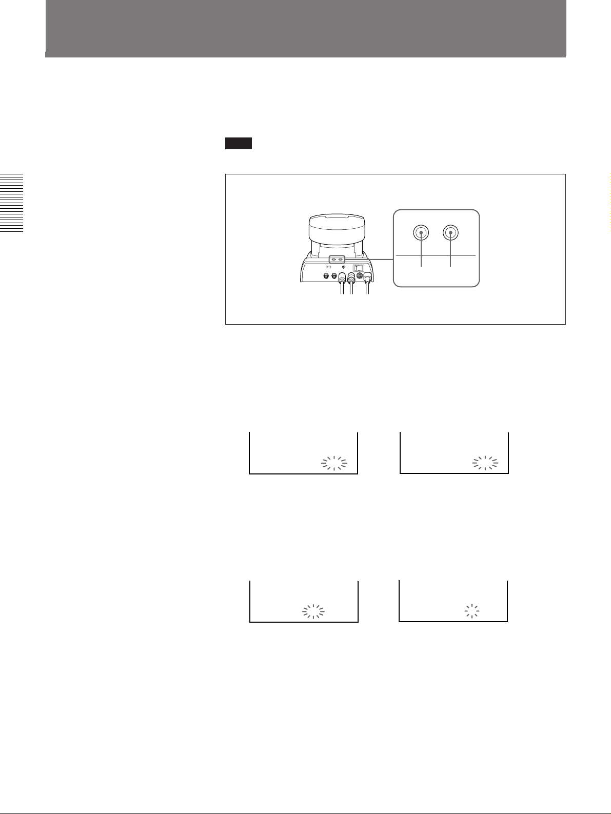
Chapter 2
1
1 1998
1
1 1998
Setting the Clock
You can display your area’s date and time on the monitor at remote
parties. It can inform the remote parties of your area’s current time.
Use the buttons on the camera unit to set the clock.
Note
When you set the clock, clear the menu from the TV monitor.
DATE TIME
DATE
button
TIME
button
1 Press the DATE and TIME buttons at the same time, and hold them
down for about two seconds.
Release your hand as the month and date appear, and the year starts
flashing.
PCS-3000 PCS-3000P
JAN
1 1998
2 Press the DATE button repeatedly to select the year.
3 Press the TIME button to set the year.
PCS-3000 PCS-3000P
2-20 Chapter 2 Settings
JAN
1 1998
Page 57
4 Repeat the steps 2 and 3 to set the other time elements in the order of
month, date, hour, and minute.
The clock starts operating as you press the TIME button to set the
minute.
PCS-3000 PCS-3000P
JUL
4 1998
3:15:01
PM
Having the clock displayed
You can select the clock display from either time or date.
To have the time displayed, press the TIME button.
To have the date displayed, press the DATE button.
To turn off the clock display, press the corresponding button again.
Note
When the power switch on the camera unit is set to OFF, the clock will be
as originally was. To retain the memory of the clock setting even if the
power is turned off, set the BACKUP switch at the rear of the camera unit
to ON.
4
7 1998
15:15:01
Chapter 2
Chapter 2 Settings 2-21
Page 58
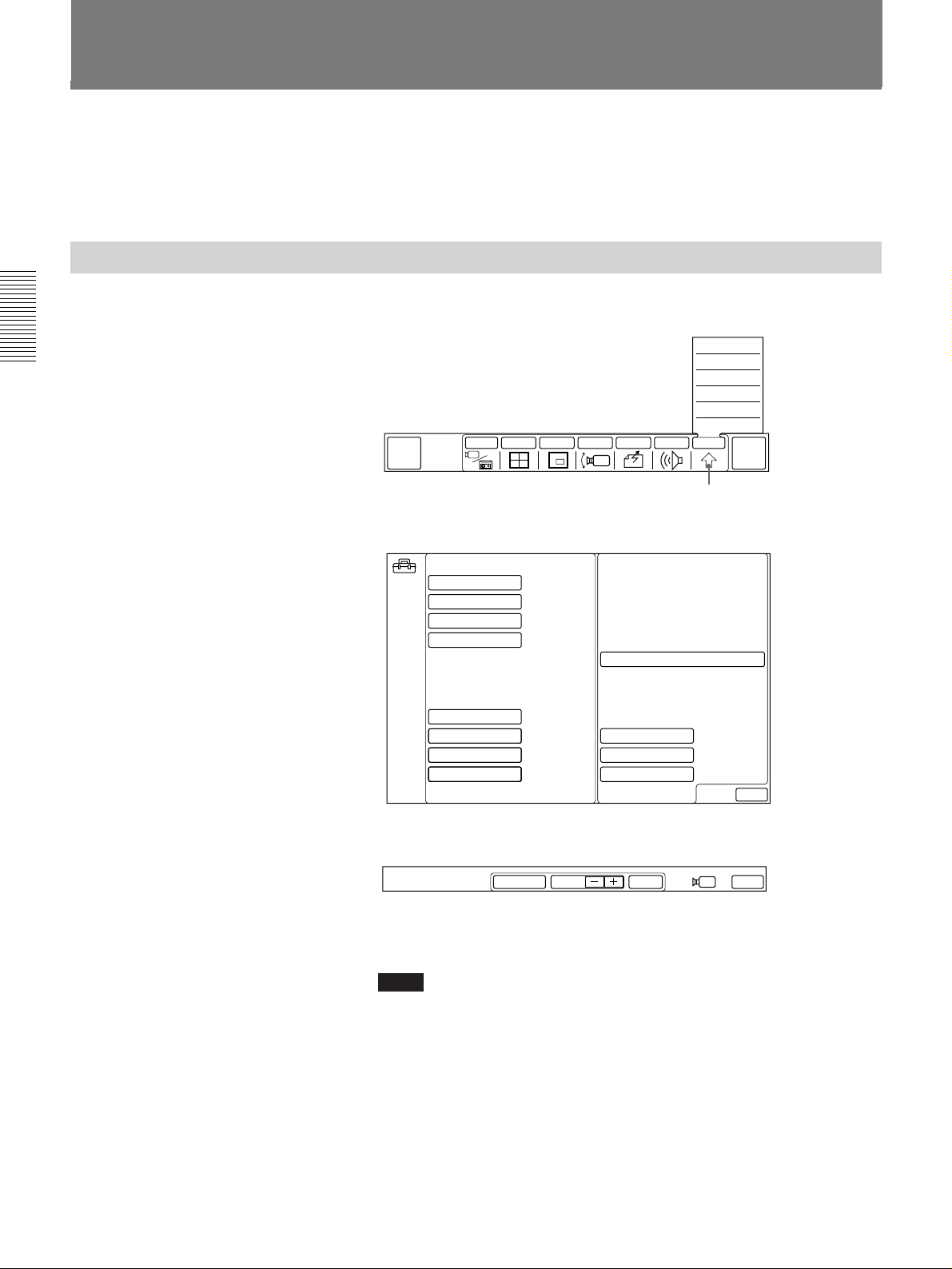
Chapter 2
Adjusting the Camera Brightness
When you shoot a subject with the light source behind the subject with a
light background, use the back light function.
You can adjust the brightness of the picture depending on the condition of
your room.
Shooting With Backlighting
1 Select [OTHER] from the MAIN menu.
The OTHER sub-menu appears.
QUICK
DIAL
2 Select [SETUP] from the OTHER sub-menu.
The SETUP menu appears.
INPUT MULTI P in P CAMERA SEND AUDIO OTHER
SETUP
STATUS
DTMF
T.120
DIAL LIST
MANUAL DIAL
[OTHER]
END OF
MEETING
SETUP
ANSWER MODE
BRI RATE
V.35 PORT
T.120/H.281
FAR END CTRL
LIP SYNCH OFF
SIRCS OUTPUT
LANGUAGE
AUTO
AUTO
SINGLE
OFF
ON
1
ENGLISH
SORT DIAL LIST
CAM BRIGHT
PERIPHERAL
LDN
EXIT
3 Select [CAM BRIGHT] from the SETUP menu.
The following menu appears.
BACK LIGHT BRIGHT EXITAUTO
4 Select [BACK LIGHT].
The BACK LIGHT icon turns to blue.
Notes
•If the AUTO icon is blue, select [AUTO] at first before selecting
[BACK LIGHT].
•Do not change any other settings.
2-22 Chapter 2 Settings
5 Select [EXIT].
The setting selected in step 3 becomes active, and the MAIN menu
appears.
To cancel the backlighting function
Select [BACK LIGHT] again so that the color of the BACK LIGHT icon
turns to its original color.
Page 59
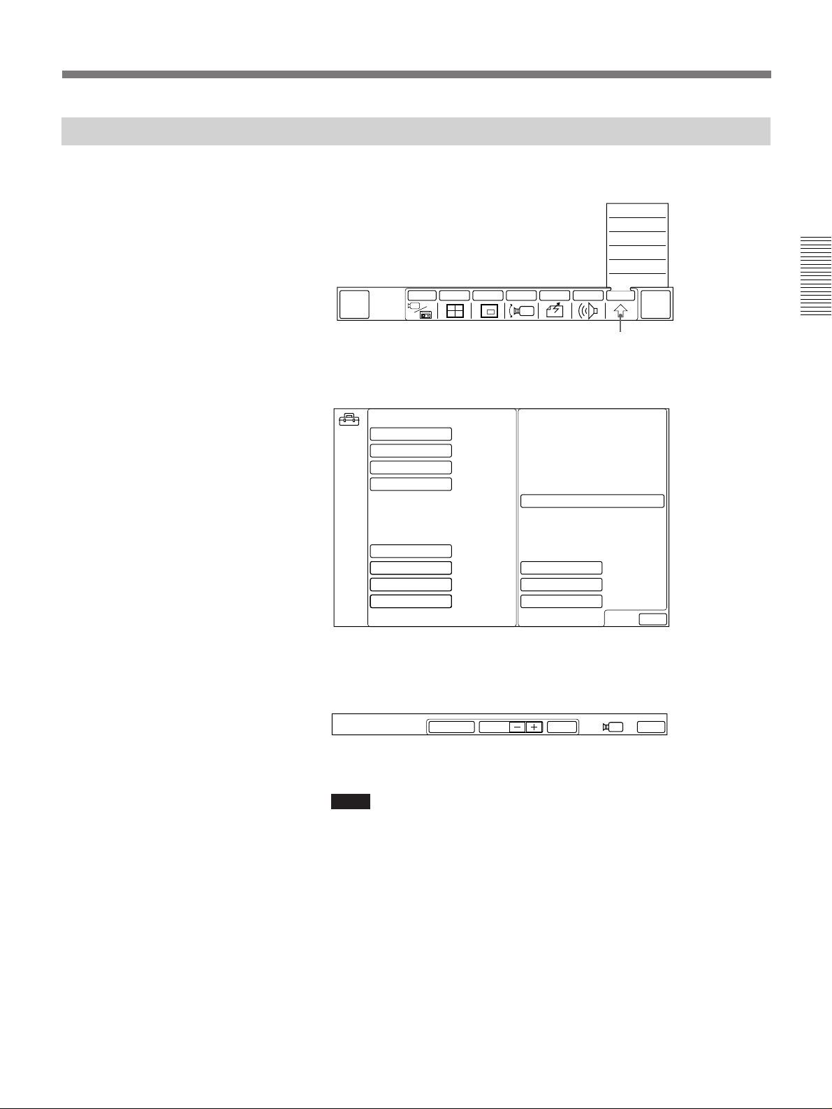
Adjusting the Brightness
1 Select [OTHER] from the MAIN menu.
The OTHER sub-menu appears.
QUICK
DIAL
INPUT MULTI P in P CAMERA SEND AUDIO OTHER
[OTHER]
2 Select [SETUP] from the OTHER sub-menu.
The SETUP menu appears.
SETUP
STATUS
DTMF
T.120
DIAL LIST
MANUAL DIAL
END OF
MEETING
Chapter 2
SETUP
ANSWER MODE
BRI RATE
V.35 PORT
T.120/H.281
FAR END CTRL
LIP SYNCH OFF
SIRCS OUTPUT
LANGUAGE
AUTO
AUTO
SINGLE
OFF
ON
1
ENGLISH
SORT DIAL LIST
CAM BRIGHT
PERIPHERAL
LDN
EXIT
3 Select [CAM BRIGHT] from the SETUP menu.
The following menu appears.
BACK LIGHT BRIGHT EXITAUTO
4 Select [+] or [–] to adjust the brightness.
Notes
•If the AUTO icon is blue, select [AUTO] at first before selecting
[BRIGHT +/–].
•Do not change any other settings.
5 Select [EXIT].
The setting selected in step 3 becomes active, and the MAIN menu
appears.
To return to automatic brightness mode
Select [AUTO] .
Chapter 2 Settings 2-23
Page 60
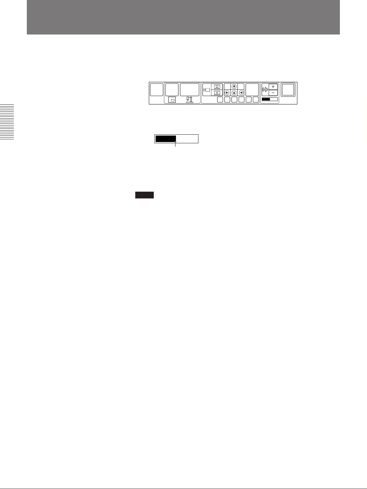
Setting the Initial Volume Level on the TV Monitor
1 Display the QUICK menu.
For details on displaying a menu, see “Switching Menus” on page 1-5.
Chapter 2
MAIN
MENU
P in P
OBJECT
PRESET
FAR
END
FA B C D E
SYSTEM
OFF
2 Set the volume to the middle position by selecting [+] or [–] .
Selected volume level
3 Adjust the volume with the TV monitor’s control.
Set it to the proper level for listening to the remote party.
Notes
•Do not change the volume with the TV monitor’s control, adjust it by
selecting the volume icons.
Each time the TV monitor’s volume is adjusted, the reflecting echoes to
the remote party will be temporarily generated.
If the reflecting echoes are not settled down, decrease the TV monitor’s
volume and increase the Rollabout Processor’s volume.
•If you have any problems, consult with qualified Sony personnel.
2-24 Chapter 2 Settings
Page 61
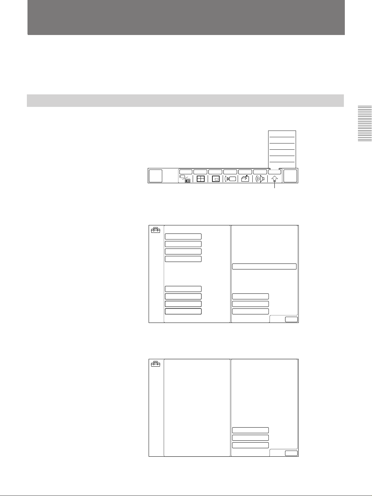
SETUP Menu
You can set various preferences in the SETUP menu.
Typically, these preferences will have been correctly set up for you by
your dealer. However, when required you can change them using the steps
described earlier.
Displaying the SETUP Menu
1 Select [OTHER] from the MAIN menu.
2 Select [SETUP] from the OTHER sub-menu.
The OTHER sub-menu appears.
QUICK
DIAL
INPUT MULTI P in P CAMERA SEND AUDIO OTHER
The SETUP menu (first page) appears.
SETUP
STATUS
DTMF
T.120
DIAL LIST
MANUAL DIAL
[OTHER]
END OF
MEETING
Chapter 2
SETUP
ANSWER MODE
BRI RATE
V.35 PORT
T.120/H.281
FAR END CTRL
LIP SYNCH OFF
SIRCS OUTPUT
LANGUAGE
AUTO
AUTO
SINGLE
OFF
ON
1
ENGLISH
SORT DIAL LIST
CAM BRIGHT
PERIPHERAL
LDN
3 Select [PERIPHERAL] from the SETUP menu.
The SETUP menu (second page) appears.
SETUP
EXIT
VID CONTROL
AUX1
AUX2
OFF
OFF
OFF
EXIT
Chapter 2 Settings 2-25
Page 62
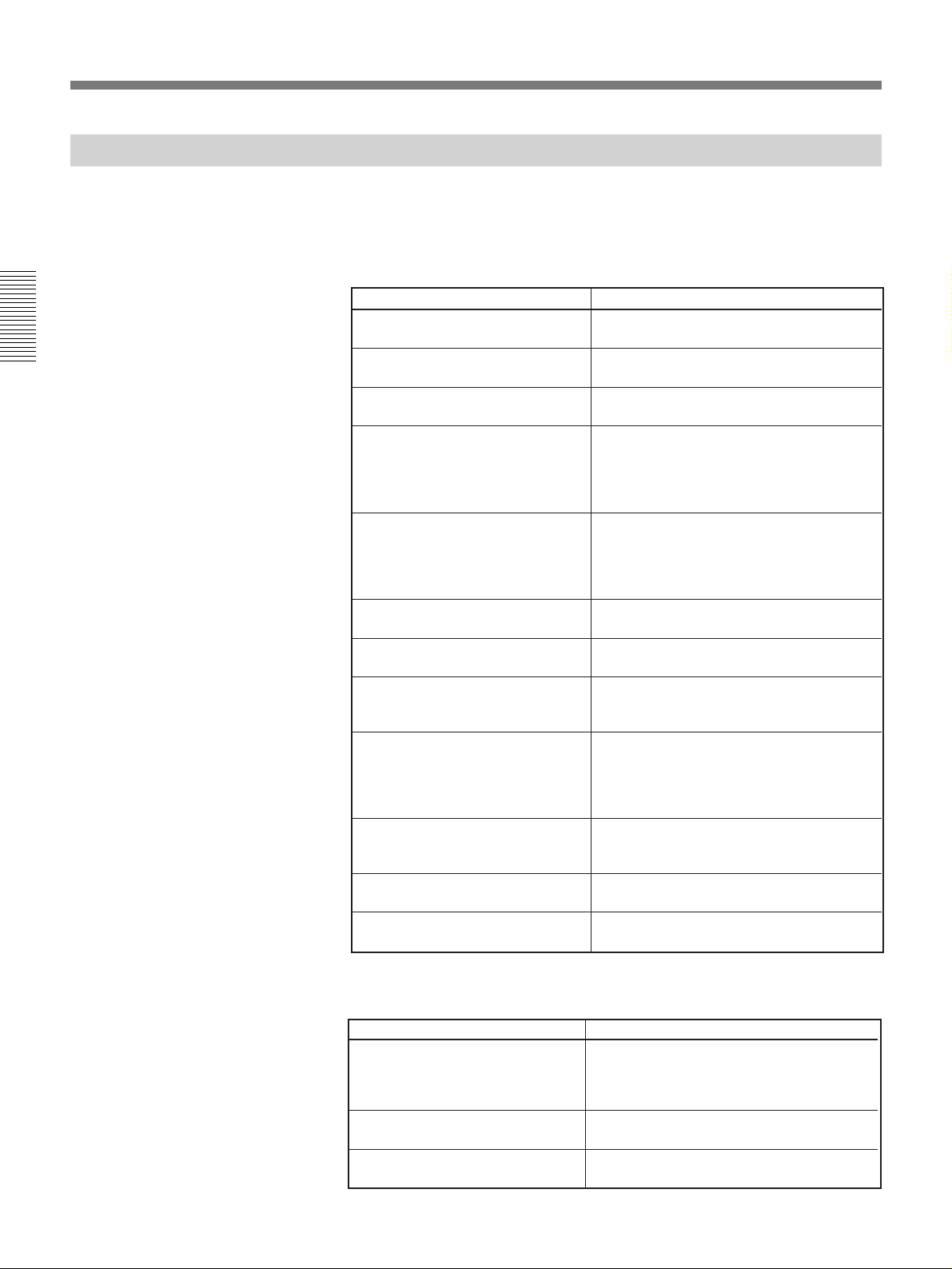
SETUP Menu
SETUP Menu Items
Chapter 2
The table below shows the items you can set or change in the SETUP
menu.
For details on displaying the SETUP menu, see page 2-25.
SETUP menu items on the first page
Setting Description
ANSWER MODE Sets the answering mode to auto or
BRI RATE Select the ISDN data transfer rate (AUTO
V.35 PORT Select SINGLE if you use one V.35
T.120/H.281 Select T.120 AUTO when having a meeting
FAR END CTRL Select ON to allow the remote party to
LIP SYNCH Sets the lip synchronization function
SIRCS OUTPUT Selects the remote control mode for the
LANGUAGE Selects language used for screen message
SORT DIAL LIST Select this item to sort a dial list in
CAM BRIGHT Adjust the brightness and set the
PERIPHERAL Select this item to go to the next SETUP
LDN Sets the sub address and local system’s
manual.
or 56K). Normally, set to AUTO.
connector. Select DUAL if you use both.
in accordance with T.120. Select H.281 ON
when controlling the remote camera in
accordance with H.281. Select OFF if you
do not use both.
switch the input or control the local camera
(angle, etc.). Select OFF if you do not want
the remote party to switch the input and
control the local camera.
settings.
Remote Commander.
displays. (page A-7.) (English, French,
German, Japanese, Spanish, or Italian).
alphabetical order.
Note that once you select this item, the
former order of the dial list cannot be
restored.
backlighting function.
2-22 and 2-23.
menu
line information.
See page 2-10 for details.
See page 2-12 for details.
For details, see pages
.
For details, see page 2-13.
2-26 Chapter 2 Settings
SETUP menu items on the second page
Setting Description
VID CONTROL Select ON when you want to control the
zoom for the VID-P100 Video Presentation
Stand (not supplied) from the Rollabout
Package.
AUX1 Select ON if additional equipment is
connected to the VIDEO IN AUX1 jack.
AUX2 Select ON if additional equipment is
connected to the VIDEO IN AUX2 jack.
Page 63
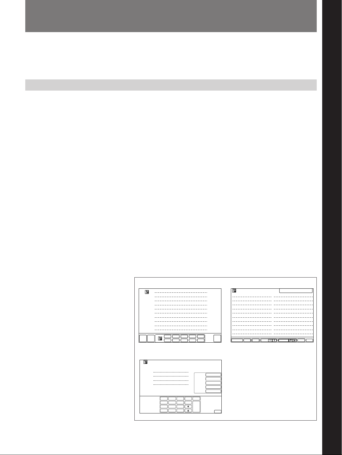
Turning the System On/Off
This section describes how to turn on and off the PCS-3000/3000P
Rollabout Package.
Switch the system on from the Remote Commander.
Turning On
The following describes how to turn on the PCS-3000/3000P Rollabout
Package.
1 Make sure the Rollabout Processor and the TV monitor are all in
standby.
For details on how to switch the TV monitor to standby, refer to the operating
instructions supplied with the TV monitor.
To switch the Rollabout Processor to standby, press the POWER switch. The
STANDBY lamp (orange) comes on.
See “Switching On for the First Time” on page 3-3.
Chapter 3 Conducting a Meeting
2 Turn on the power of any other equipment to be used during the
meeting.
3 Press the POWER ON button on the Remote Commander.
This turns on the Rollabout Processor, the camera unit, and the TV
monitor.
The POWER lamps on the camera unit and the Rollabout Processor
light up. The camera unit performs training movements (moves up,
down, left, right). The picture of the local camera appears. If you
operate the Rollabout Processor with the Remote Commander, The
QUICK DIAL, DIAL LIST or MANUAL DIAL menu—whichever
was displayed last—appears on the TV monitor:
DIAL LIST menu
SETUPDELETE PAGE EXITDIALSELECTMULTI
SELECTED 001
011 Dallas branch
012 Los Angeles branch
013 San Diego branch
014 New Orleans branch
015 Cleveland branch
016 Pittsburgh branch
017 Philadelphia branch
018 Atlanta branch
019 Denver branch
020 Memphis branch
MAIN
MENU
LIST
QUICK DIAL menu
# 1 Boston branch
# 2 Montreal branch
# 3 Chicago branch
# 4 Seattle branch
# 5 Buffalo branch
# 6 Detroit branch
# 7 San Francisco branch
# 8 Miami branch
# 9 Toronto branch
# 10 Ottawa branch
# 1
QUICK
MENU
# 6
LIST
001 Boston branch
002 Montreal branch
003 Chicago branch
004 Seattle branch
005 Buffalo branch
006 Detroit branch
007 San Francisco branch
008 Miami branch
009 Toronto branch
# 2
# 3
# 4
# 5
# 7
# 8
# 9
SYSTEM
# 10
010 Ottawa branch
OFF
Chapter 3
MANUAL DIAL menu
MANUAL DIAL
A1
A2
B1
B2
1
GHI
4
PQRS
7
∗
LINE I/F
BRI
LINE RATE
AUTO
7K
AUDIO BAND
T.120/H.281
OFF
H.261
VIDEO MODE
15FPS
2
3
clear
delete
ABC
DEF
JKL
MNO
5
6
copy
TUV
WXYZ
8
9
0
DIAL
#
EXIT
Chapter 3 Conducting a Meeting 3-1
Page 64
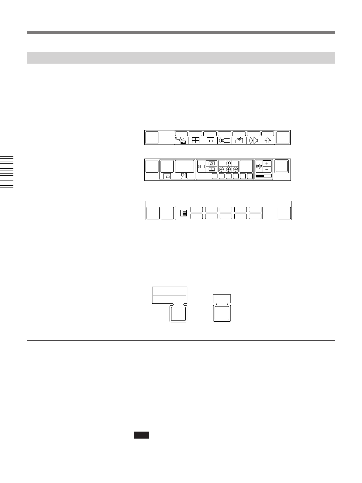
Menus
Turning the System On/Off
Turning Off
The following describes how to turn off the PCS-3000/3000P Rollabout
Package.
1 Display the MAIN menu, QUICK menu, or QUICK DIAL menu.
For details on displaying a menu, see “Switching Menus” on page 1-5.
MAIN menu
MULTI P in P CAMERA SEND AUDIO OTHER
QUICK
MENU
INPUT
QUICK menu
END OF
MEETING
Chapter 3
MAIN
MENU
P in P
OBJECT
PRESET
FAR
END
FA B C D E
SYSTEM
OFF
QUICK DIAL menu
# 1
# 2
# 3
# 4
MAIN
MENU
QUICK
MENU
# 6
# 7
# 8
# 9
# 5
# 10
SYSTEM
OFF
2 When in the MAIN menu, select [END OF MEETING] and then select
[SYSTEM OFF].
When in the QUICK or QUICK DIAL menu, select [SYSTEM OFF]
and then select [OK].
The Rollabout Processor, camera unit, and TV monitor are all turned
off and the whole system goes into standby.
SYSTEM OFF
HANG UP
END OF
MEETING
OK
SYSTEM
OFF
The Rollabout Package power status
The POWER switches on the Rollabout Processor and on the camera
unit should remain in the ON position after you turn off the system.
This allows you to start the system and display the menu instantly when
you press the POWER ON button on the Remote Commander. If the
Rollabout Processor POWER switch is turned off, the system will not
be able to receive calls from a remote party.
When the system is in standby, you can turn the system on with the
POWER ON button on the Remote Commander, and turn the power off
from the on-screen menus.
Note
If you do not use the system for an extended period, turn off the POWER
switch.
3-2 Chapter 3 Conducting a Meeting
Page 65
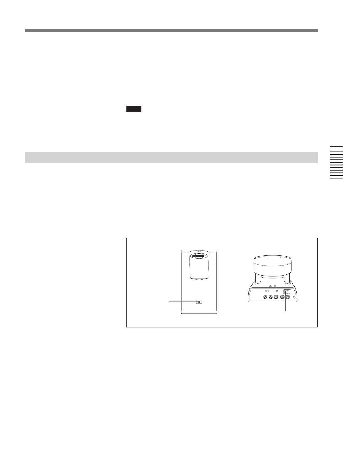
To adjust the TV monitor screen
Use the controls on the TV monitor to adjust the screen (picture, hue,
contrast, brightness, and sharpness). This is particularly important when
you use the VID-P100 Video Presentation Stand (not supplied) to capture
objects or documents.
Refer to the operating instructions supplied with the TV monitor and adjust the
screen.
Note
Do not activate the function of the TV monitor, such as the surround
function. Otherwise, the sound from the speaker is strange since the echo
canceller on the Rollabout Processor does not function correctly.
Switching On for the First Time
Confirm that the power of the Rollabout Processor is turned off.
1 Confirm that the POWER and BACKUP switches on the camera unit
are set to ON.
2 Press the POWER switch on the Rollabout Processor.
The STANDBY lamp (orange) flashes; when the system switches to
standby, the STANDBY lamp stays on.
Chapter 3
POWER switch
6
BUSY
Switching the Rollabout Package to standby
POWER switch
Chapter 3 Conducting a Meeting 3-3
Page 66
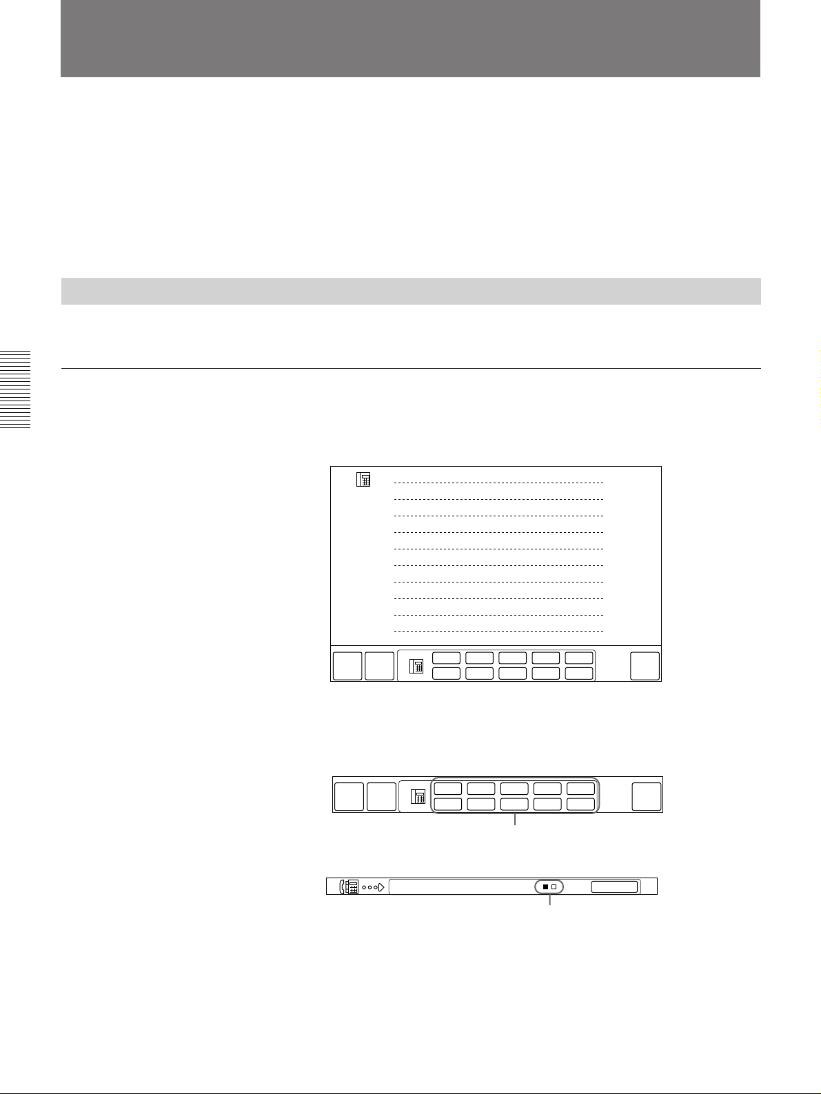
Starting a Meeting
You can start a meeting with a remote party by dialing from the menu.
Once you have made a connection with the remote party, you can begin
talking with them. You can begin a meeting by calling the remote party
yourself, or you can wait for them to call you. The following describes
how to call a remote party, and how to receive a call from a remote party.
With beforehand registration of remote parties’ names and line numbers,
quick and easy dialing can be done.
For details, see “Registering a Remote Party” on page 2-1.
Calling a Remote Party
The following describes how to call a remote party.
To call remote parties registered in index #1 to #10
1 Display the QUICK DIAL menu.
Chapter 3
For details on displaying the QUICK DIAL menu, see “Switching Menus” on
page 1-5.
# 1 Boston branch
LIST
# 2 Montreal branch
# 3 Chicago branch
# 4 Seattle branch
# 5 Buffalo branch
# 6 Detroit branch
# 7 San Francisco branch
# 8 Miami branch
# 9 Toronto branch
# 10 Ottawa branch
# 1
# 2
# 3
# 4
MAIN
MENU
QUICK
MENU
# 6
# 7
# 8
# 9
# 5
# 10
SYSTEM
OFF
2 Select the index number icon of the remote party you want to call (#1,
#2, #3, ...#10).
The system automatically dials the selected number.
# 1
# 2
# 3
# 4
MAIN
QUICK
MENU
MENU
# 6
# 7
Index number icon
# 8
While the system is dialing the remote party, the following appears:
# 9
# 5
# 10
SYSTEM
OFF
3-4 Chapter 3 Conducting a Meeting
Boston branch
Only the number of lines registered appears
(turns blue upon connection)
CANCEL
When the connection is completed, the “MEETING STARTS!”
message appears.
To cancel a call before it is connected
Select [CANCEL].
Page 67
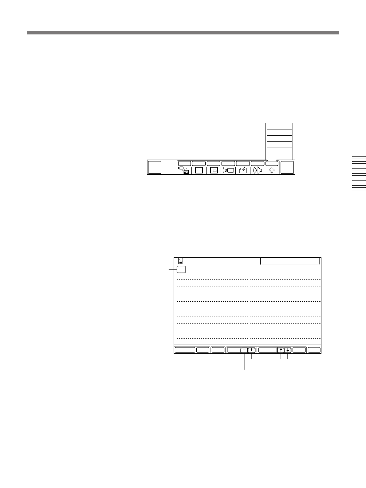
To call remote parties registered in index #11 or higher
To call a remote party registered in index #11 to #120, follow the steps
below. (You can also call a remote party in index #1 to #10 using the same
method.)
If the DIAL LIST menu is already displayed, start from step 3.
1 Select [OTHER] from the MAIN menu.
The OTHER sub-menu appears.
QUICK
DIAL
INPUT MULTI P in P CAMERA SEND AUDIO OTHER
SETUP
STATUS
DTMF
T.120
DIAL LIST
MANUAL DIAL
[OTHER]
END OF
MEETING
2 Select [DIAL LIST].
The DIAL LIST menu appears.
3 Select the index number of the remote party you want to call by using
[>] or [.].
The color of the selected remote party index number changes to blue.
For details on conducting a meeting with multiple remote parties, see
“Holding a Meeting With Multiple Remote Parties” on page 1-19.
Selected
index
number
LIST
001 Boston branch
002 Montreal branch
003 Chicago branch
004 Seattle branch
005 Buffalo branch
006 Detroit branch
007 San Francisco branch
008 Miami branch
009 Toronto branch
010 Ottawa branch
SETUPDELETE PAGE EXITDIALSELECTMULTI
[PAGE –]
SELECTED 001
011 Dallas branch
012 Los Angeles branch
013 San Diego branch
014 New Orleans branch
015 Cleveland branch
016 Pittsburgh branch
017 Philadelphia branch
018 Atlanta branch
019 Denver branch
020 Memphis branch
[PAGE +]
[>]
[.]
Chapter 3
•Select [PAGE +] to move to the next DIAL LIST page.
•Select [PAGE –] to move to the previous DIAL LIST page.
Chapter 3 Conducting a Meeting 3-5
(Continued)
Page 68
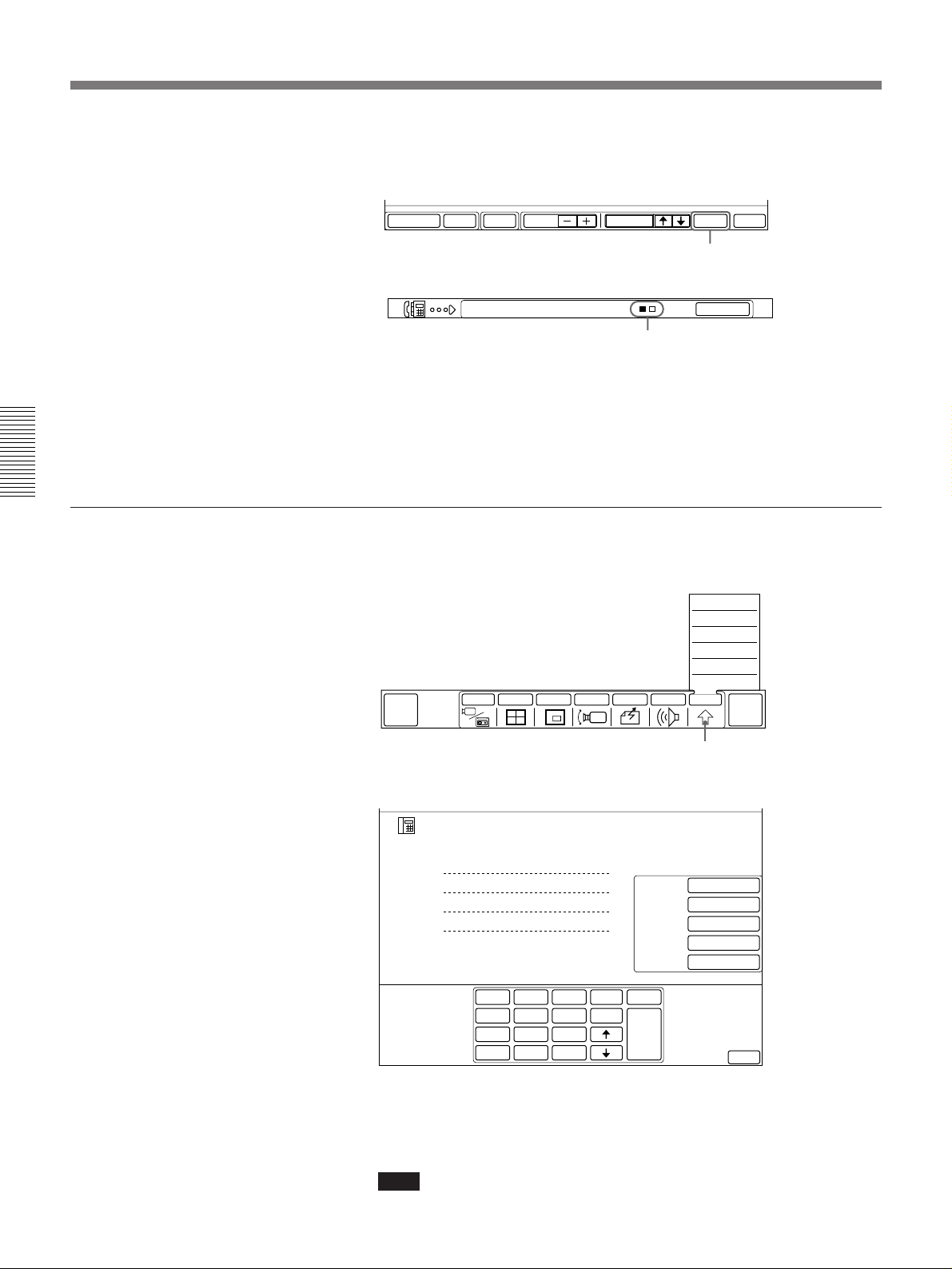
Starting a Meeting
4 Select [DIAL].
The system automatically dials the selected remote party.
SETUPDELETE PAGE EXITDIALSELECTMULTI
[DIAL]
While the system is dialing, the following is displayed:
Chapter 3
To call unregistered remote parties
Boston branch
CANCEL
Only the lines
registered appear (turn blue upon connection).
When the connection is completed, the “MEETING STARTS!”
message appears.
To cancel dialing before the call is connected
Select [CANCEL].
When the MANUAL DIAL menu is on the screen, skip the steps 1 and 2.
1 Select [OTHER] from the MAIN menu.
The OTHER sub-menu appears.
QUICK
DIAL
INPUT MULTI P in P CAMERA SEND AUDIO OTHER
SETUP
STATUS
DTMF
T.120
DIAL LIST
MANUAL DIAL
[OTHER]
END OF
MEETING
2 Select [MANUAL DIAL] from the OTHER sub-menu.
The MANUAL DIAL menu appears.
3-6 Chapter 3 Conducting a Meeting
MANUAL DIAL
A1
A2
B1
B2
1
2
GHI
4
PQRS
7
∗
3
ABC
DEF
JKL
MNO
5
6
TUV
WXYZ
8
9
0
#
delete
copy
clear
DIAL
BRI
AUTO
7K
OFF
H.261
15FPS
LINE I/F
LINE RATE
AUDIO BAND
T.120/H.281
VIDEO MODE
EXIT
3 Enter the line number of the remote party to have a meeting with.
The way to use on-screen keyboards in the MANUAL DIAL menu is the same
as one in the DIAL LIST menu. For details, see “To use the on-screen
keyboard” on page 2-5.
Note
Although there are alphabets on some keys, it does not indicate that
alphabets can be input.
Page 69
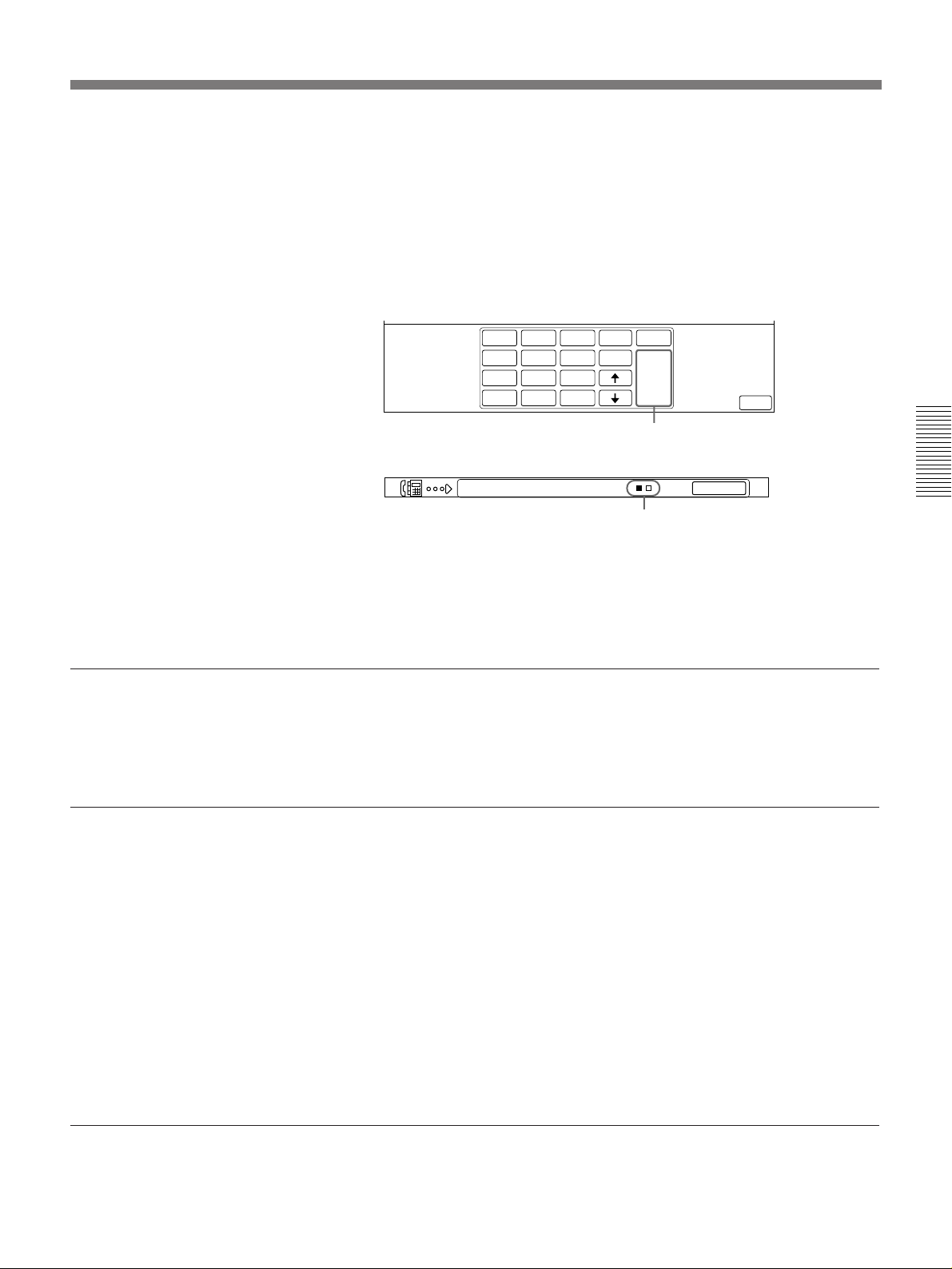
4 Set the LINE I/F, LINE RATE, AUDIO BAND, T.120/H.281 and
VIDEO MODE.
The settings of each item in the MANUAL DIAL menu are the same
as those in the DIAL LIST menu.
For details, see pages 2-3 and 2-4.
5 Select [DIAL].
The system automatically dials the selected remote party.
1
2
4
GHI
7
PQRS
∗
3
ABC
DEF
5
6
JKL
MNO
8
9
TUV
WXYZ
0
#
While the system is dialing, the following is displayed:
delete
copy
clear
DIAL
EXIT
DIAL
To cancel dialing before the call is connected
Select [CANCEL].
When the call is connected
The local party appears on the remote TV monitor and the remote party
appears on your TV monitor. You can then start your meeting.
To adjust the volume or camera, see “ Basic Adjustments” on pages 1-9.
If the remote party is not available
If the remote party system is set to the auto answer mode, the remote
scene will appear on the local TV monitor but there may be no
participants. If it is set to the manual answer mode, the remote system may
just keep ringing. In either case, disconnect the call.
Boston branch
Only the lines
registered appear (turn blue upon connection).
CANCEL
When the connection is completed, the “MEETING STARTS!”
message appears.
Chapter 3
If a message appears
To disconnect a call
If the remote system is set to the auto answer mode, select [END OF
MEETING] from the MAIN menu, then select [OFF LINE].
For details, see “Ending a Meeting” on page 3-11.
If the remote system is set to the manual answer mode, select [CANCEL]
on the screen (shown in step 2 on page 3-4 or step 4 on page 3-6).
The call is disconnected and your system switches to standby.
When the lines cannot be connected for some reason, a message appears
on the upper corner of the TV monitor.
For details on message meanings and solutions, see “Message List” on page A-7.
Chapter 3 Conducting a Meeting 3-7
Page 70
Starting a Meeting
Receiving a Call
When a call comes in, the operation differs depending on whether the local
system is in auto answer mode or manual answer mode.
For details on how to set the answer mode, see “ Setting the Answer Mode” on
page 2-9.
Whichever mode you choose, the Rollabout Processor must be fully turned
on, or be in the standby mode to receive a call.
The system goes into standby after the Rollabout Processor POWER
switch has been turned on and the STANDBY lamp has lit up in orange.
When in standby, you can then press the POWER ON button on the
Remote Commander to turn on the system.
Make sure that the TV is in standby.
If the local system is in the auto answer mode
Chapter 3
When a call comes in, the system automatically receives the call.
When the system is in standby, or the menu is displayed:
•The power will turn on automatically (if the system is in standby).
•The following message appears on the screen.
AUTO RECEIVE CALL IN PROGRESS
The Rollabout Processor starts ringing, and the connection is completed
after a few seconds.
When the connection has been made, the remote party appears on your TV
monitor and the sound becomes active. Also, a “MEETING STARTS!”
message appears, with the MAIN or QUICK menu. You may start your
meeting at this time.
If you are operating the system when a call comes in:
The “PLEASE GO TO MAIN MENU TO ANSWER CALL” message
appears, finish the current operation. If you cannot receive the call
according to your current operations, ignore it and continue with the
current operation.
3-8 Chapter 3 Conducting a Meeting
When the system fails to make a connection:
The “CANNOT COMPLETE CONNECTION” message appears along
with a 3-digit error number. If the system was in standby before the call
came in, the system will revert to standby. If the power is turned on, you
can use the menu to perform other operations.
For details on definitions of error numbers, see page A-8.
Page 71
To answer calls in the manual answer mode
When your system is in the manual answer mode, you need to connect
incoming calls manually.
When the Rollabout Processor starts ringing, follow the steps below.
1 If you are operating the system and the “PLEASE GO TO MAIN
MENU TO ANSWER CALL” message appears, finish the current
operation.
The following manual answer menu appears on the screen.
If you cannot receive the call according to your current operation,
ignore it and continue with the current operation.
When the remote party abandons the call, the Rollabout Processor
stops ringing and the manual answer menu disappears.
2 Select [ACCEPT].
The call is connected.
Once the connection is made, the MAIN or QUICK menu appears, the
remote party appears on local TV monitor, local party appears on the
remote TV monitor and a meeting becomes possible.
The “MEETING STARTS!” message appears.
ACCEPT REJECT
Chapter 3
If you do not want to receive a call, select [REJECT] from the
manual answer menu in step 1.
The Rollabout Processor stops ringing.
If the call fails to be connected, the “CANNOT COMPLETE
CONNECTION” message appears.
Chapter 3 Conducting a Meeting 3-9
Page 72
Starting a Meeting
To start a meeting using non-ISDN lines
Chapter 3
If you connect via the V.35 interface with private lines or a terminal
adapter, start the meeting as follows:
If you are using a V.35 interface and are making connection with a remote
party which “V” has been entered on the telephone number column in the
DIAL SETUP menu, select the remote party you want to connect with
from the DIAL LIST menu and select [DIAL] at both local and remote
parties.
If you are using a terminal adapter, connect the line at the terminal adapter
side first.
If you are using a V.35 interface and are making connection with a remote
party which “V” has not been entered on the telephone number column in
the DIAL SETUP menu, select the remote party you want to connect from
the DIAL LIST menu and select [DIAL].
This automatically connects your system to the remote party.
Note
If you use an ISDN line, be sure to turn off any other equipment with
automatic answering functions (e.g., G4 facsimile) connected to it.
To record a meeting
You can record a meeting on a VCR.
For details, see “Recording a Meeting” on page 4-10.
3-10 Chapter 3 Conducting a Meeting
Page 73
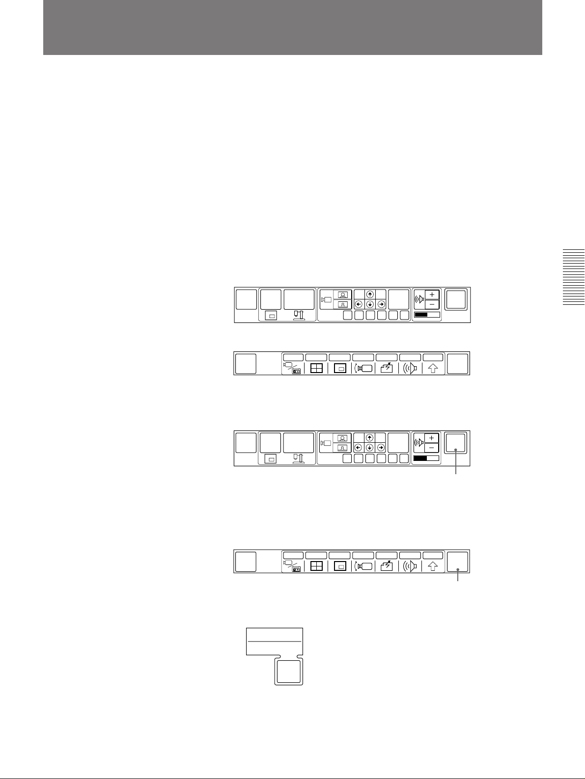
Ending a Meeting
You can end a meeting in one of the following two ways:
•Disconnect the call while leaving the main power on to perform other
operations.
•Disconnect the call and turn off the system.
In either case, use the menu to end the meeting.
Pressing the POWER ON button on the Remote Commander will not turn
off the power.
Follow the steps below.
If the MAIN menu is displayed, choose the method for finishing the
meeting in step 3.
1 Display the QUICK or MAIN menu.
For details, see “Switching Menus” on page 1-5.
QUICK menu
MAIN
MENU
P in P
OBJECT
PRESET
FAR
END
FA B C D E
SYSTEM
OFF
MAIN menu
QUICK
MENU
INPUT
END OF
MEETING
MULTI P in P CAMERA SEND AUDIO OTHER
2 If the QUICK menu is on the screen, select [SYSTEM OFF] and then
select [OK].
MAIN
MENU
P in P
OBJECT
PRESET
FAR
END
FA B C D E
The Rollabout Processor, camera unit, and TV are turned off and
switched to standby.
If the MAIN menu is on the screen, select [END OF MEETING].
MULTI P in P CAMERA SEND AUDIO OTHER
QUICK
MENU
INPUT
SYSTEM
OFF
[SYSTEM OFF]
END OF
MEETING
Chapter 3
The END OF MEETING sub-menu appears.
SYSTEM OFF
HANG UP
END OF
MEETING
Chapter 3 Conducting a Meeting 3-11
[END OF MEETING]
(Continued)
Page 74

Ending a Meeting
Chapter 3
3 When you are operating from the MAIN menu, select [HANG UP] if
you want to disconnect the line and continue performing other
operations. Select [SYSTEM OFF] to set the system to the standby
mode.
To continue your meeting, select [END OF MEETING] again in
step 3.
When you end your multi meeting
If you have held a multi meeting, the icon [HANG UP] is changed to
[HANG UP ALL]. Select [HANG UP ALL] to end a meeting.
3-12 Chapter 3 Conducting a Meeting
Page 75
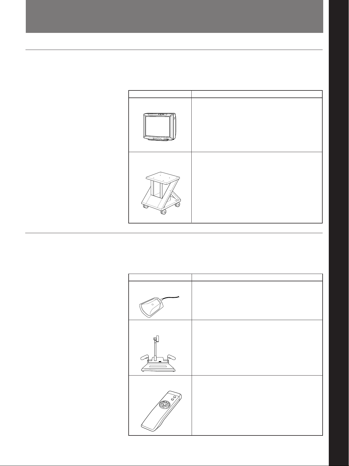
Options
TV and cabinet
Chapter 4 Operation of Optional Items
The following options are available for use with the meeting system.
TV and cabinet
Item Description
TV monitor The TV is used as a meeting monitor and speakers.
It displays the remote party, graphics, and icons.
PCS-F500/F510 The cabinet houses the Rollabout Processor and
Cabinet supports the TV monitor.
Other options
Chapter 4
The following optional devices are also available to enhance your
meetings.
Options
Item Description
PCS-A300 Microphone unit; allows you to
Microphone accommodate extra two or three participants.
Up to one PCS-A300 Microphone may be added to a
system.
VID-P100 Video Captures still objects and documents in color
Presentation Stand for transmission to remote parties.
PCS-R500 Identical to the Remote Commander included in
Remote Commander the basic system. You may purchase it as a backup to
the original.
(Continued)
Chapter 4 Operation of Optional Items 4-1
Page 76
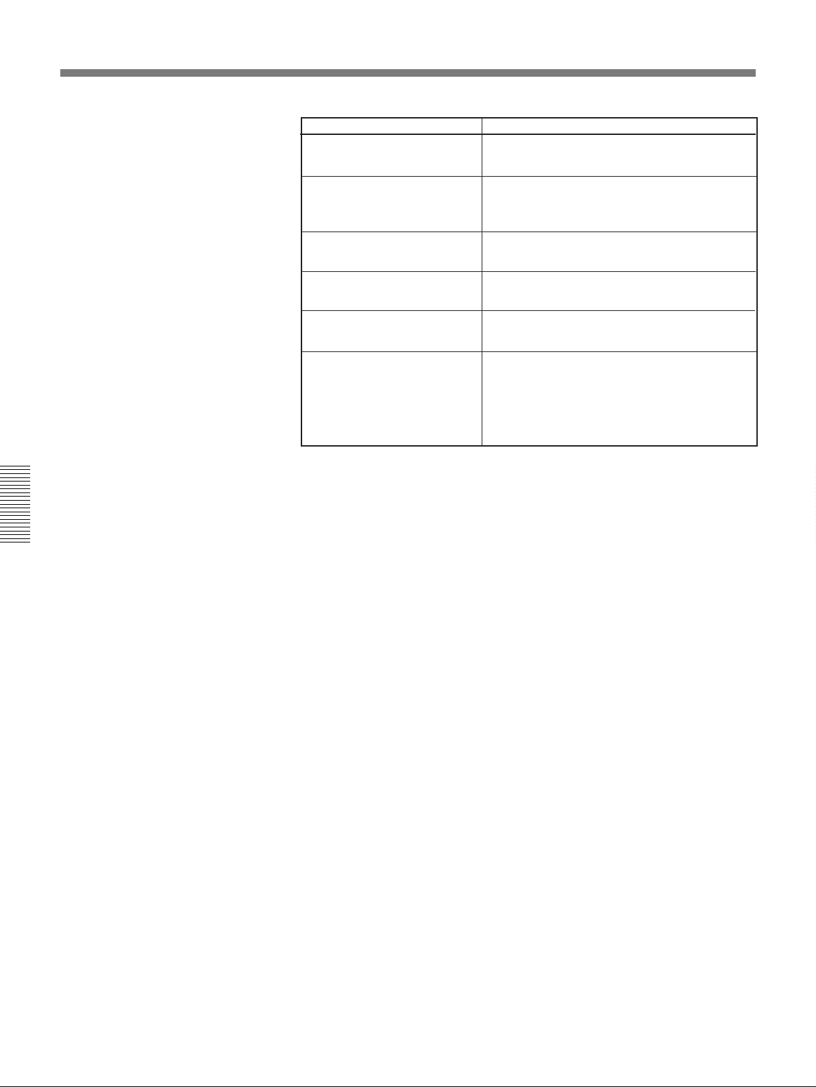
Options
Item Description
PCS-I500 Provides a V.35 line interface.
V.35 Interface Board
PCS-K32 Connects the V.35 connector (V.35 interface
V.35 Conversion Connector board – PCS-I500) to the terminal adapter.
Cable (1 m, 3.3 ft)
PCS-I300 Provides the second ISDN jack to the Rollabout
BRI Board Processor.
Chapter 4
PCS-K60 S-video cord Cord for connecting video equipment with S-
video connector.
PCS-R510 Key Commander Allows selection and execution of menu icons
with a one-touch key.
PCS-T300 Tablet Controls the system instead of using the
Remote Commander. Connect to the VID.
CONTROL connector on the Rollabout
Processor. (The VID. CONTROL connector is
for both of the video presentation stand and the
tablet.)
4-2 Chapter 4 Operation of Optional Items
Page 77
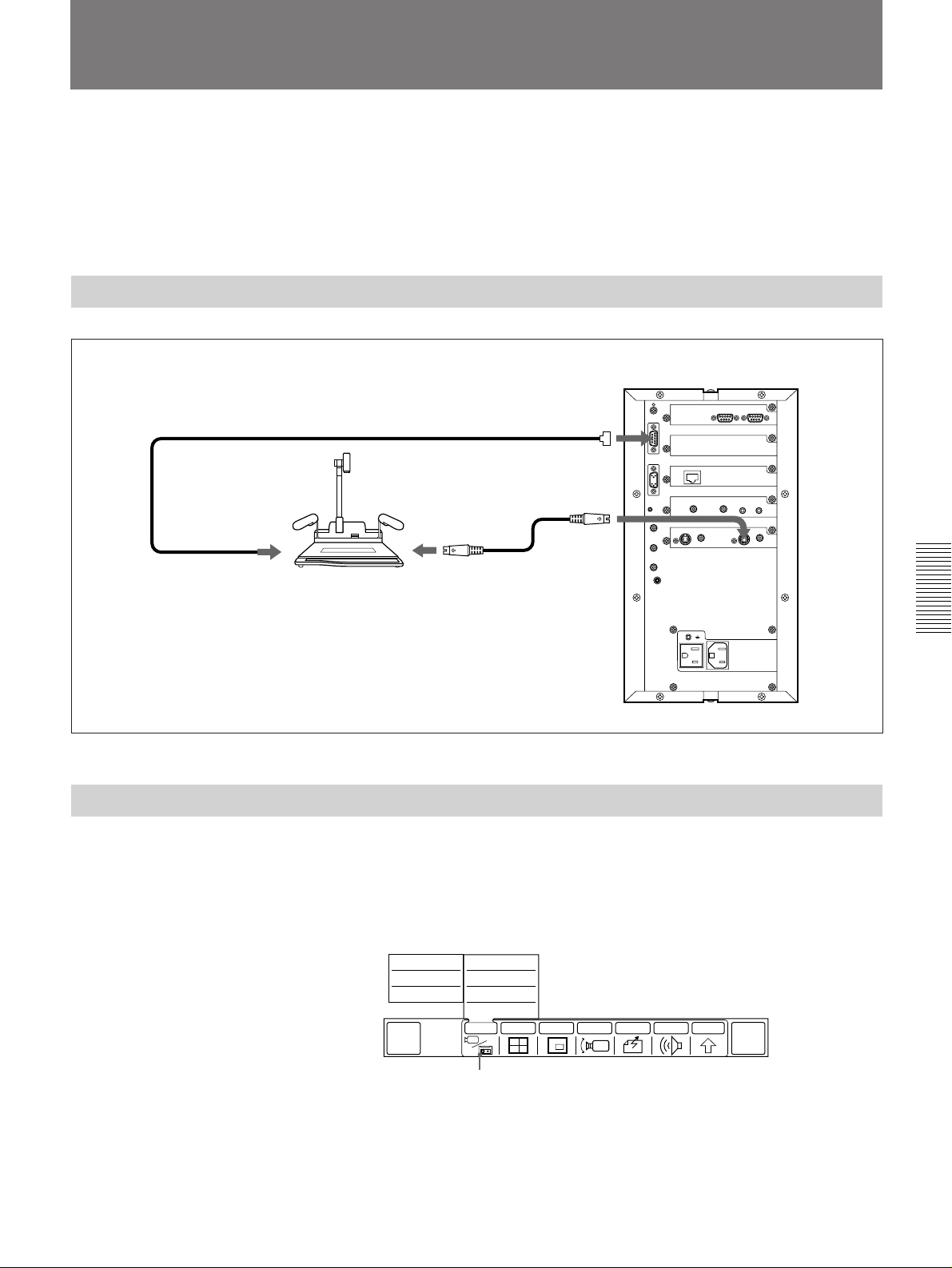
Sending Images from the Video Presentation
Stand
You can use the VID-P100 Video Presentation Stand (not supplied) to
send still color pictures of documents or objects.
You can also send video by connecting video equipment to an S video
output jack of the Rollabout Processor.
Refer to the operating instructions supplied with the VID-P100 Video
Presentation Stand .
Connecting the Video Presentation Stand
Rollabout Processor
Connection cable (not supplied)
VID-P100 Video
Presentation
Stand
to RS-232C
PCS-K60
Connection cable
(not supplied)
to S VIDEO OUT
Connecting the video presentation stand
to VID CONTROL
to VIDEO
IN AUX1
Sending a Still Picture from the Video Presentation Stand
1 Make sure the video presentation stand is turned on.
Chapter 4
2 Place a document or an object on the stand.
3 Select [INPUT] from the MAIN menu, then select [NEAR AUX1].
FAR
AUX2
FAR
AUX1
FAR
MAIN CAM
QUICK
MENU
The object on the video presentation stand appears on the local and
remote TV monitors.
NEAR
AUX2
NEAR
AUX1
NEAR
MAIN CAM
SOURCE VIEW
MULTI P in P CAMERA SEND AUDIO OTHER
INPUT
[INPUT]
END OF
MEETING
(Continued)
Chapter 4 Operation of Optional Items 4-3
Page 78
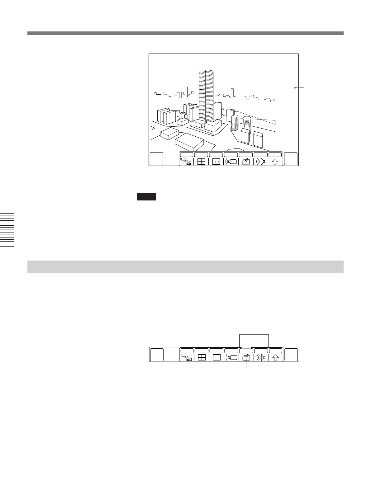
Sending Images from the Video Presentation Stand
INPUT
MULTI P in P CAMERA SEND AUDIO OTHER
Chapter 4
QUICK
MENU
•Make sure the image is clear and correctly oriented. Make any
necessary adjustments on the video presentation stand.
Notes
•If the video presentation stand is turned off after selecting [NEAR
AUX1] from the INPUT sub-menu, the picture may be distorted. In this
case, turn on the video presentation stand. The correct picture will appear.
•If you perform special playback functions, such as pause, on a VCR
connected to the Rollabout Processor instead of the video presentation
stand, the picture may appear distorted.
END OF
MEETING
Image from video
presentation
stand
Sending Moving Picture As Still Pictures Continuously
When you send pictures that contain lots of text, we recommend you to
send that picture as a still picture. Since a still picture is more clear than
moving picture for reading text.
You can send still pictures continuously, or one by one.
1 Select [SEND] from the MAIN menu.
CONTINUOUS
1 SHOT
MULTI P in P CAMERA SEND AUDIO OTHER
QUICK
MENU
INPUT
[SEND]
2 Select [CONTINUOUS].
The moving picture is frozen and the still picture is continuously sent
to the remote party.
END OF
MEETING
4-4 Chapter 4 Operation of Optional Items
Page 79
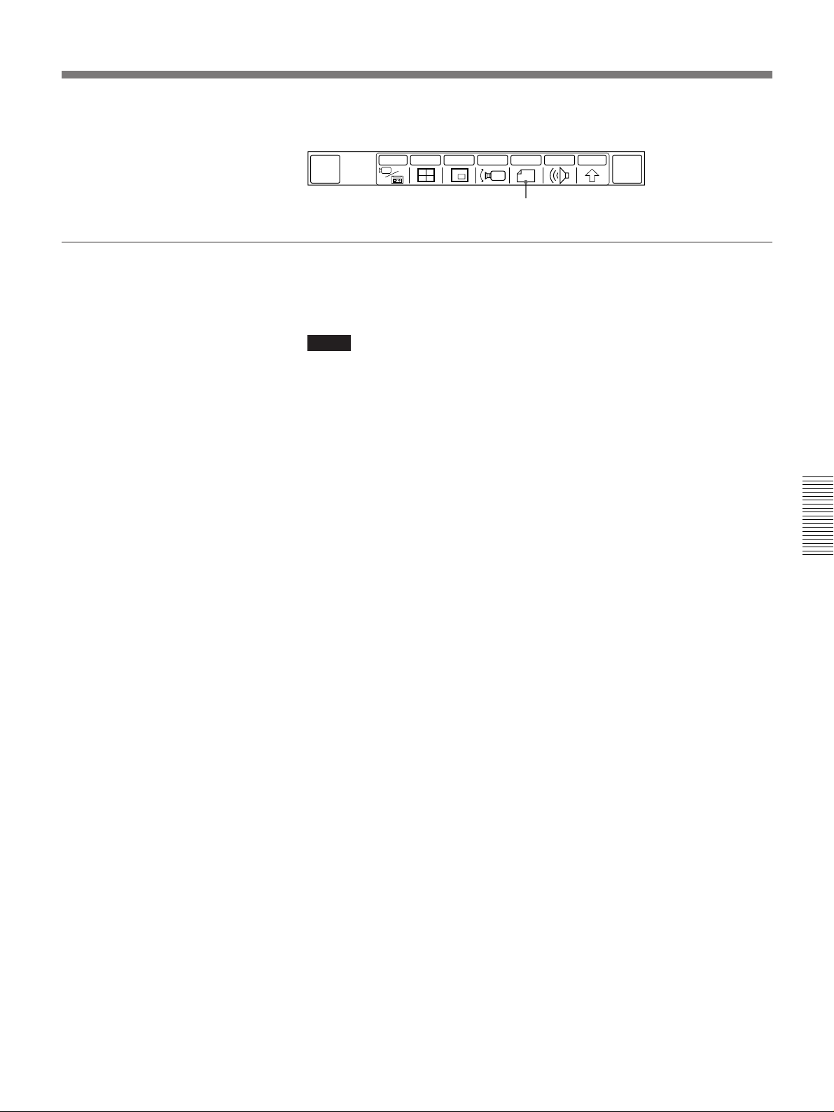
To send one still picture
To stop sending the still picture
Operate the Remote Commander to display the menu, then select [STOP].
QUICK
MENU
INPUT
[STOP]
END OF
MEETING
MULTI P in P CAMERA STOP AUDIO OTHER
Select [1 SHOT] at the step 2. A still picture is sent to the remote party.
Notes
•The interval between still pictures depends on the transmission rate.
•The picture can only be sent if the remote party is displaying the MAIN
menu, QUICK menu, or when no menu is displayed.
Chapter 4
Chapter 4 Operation of Optional Items 4-5
Page 80
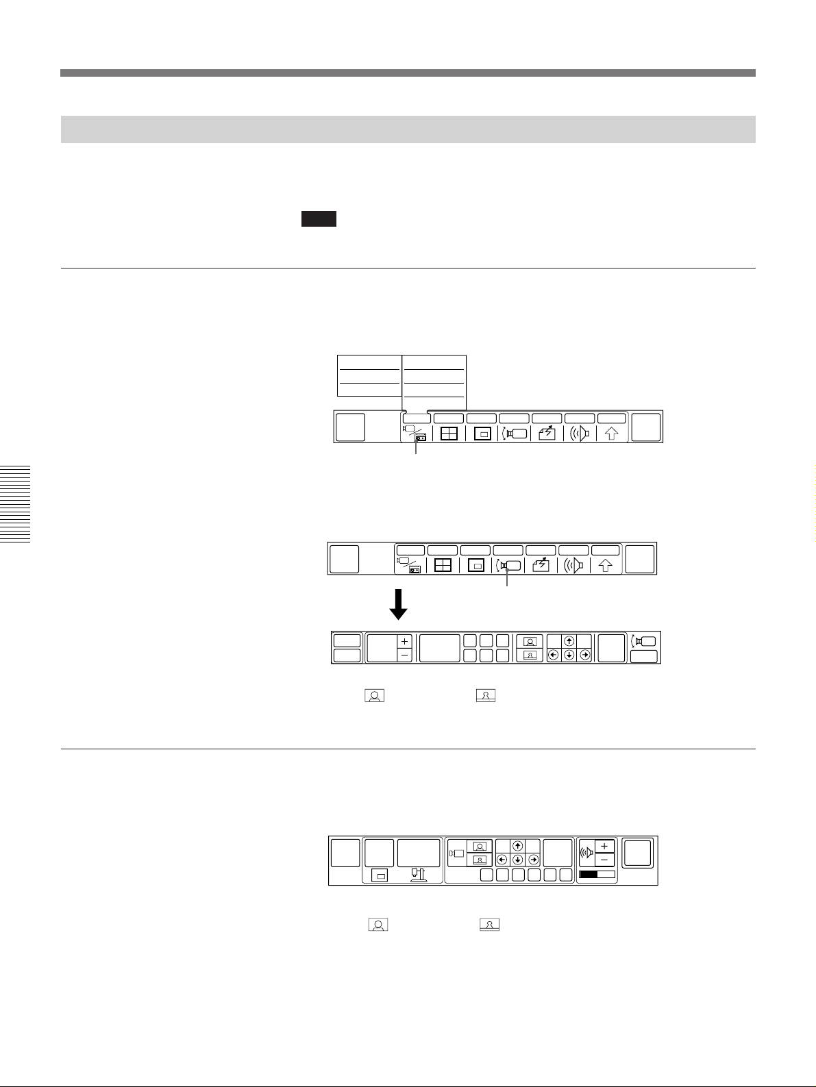
Sending Images from the Video Presentation Stand
Controlling Zoom With the Menu
The zoom of the VID-P100 Video Presentation Stand can be controlled
with the Rollabout Processor.
Note
Items at the left are only displayed when it is on line.
To control with the CAMERA menu
1 Select [INPUT] from the MAIN menu and then select [NEAR AUX1].
The picture from the video presentation stand is displayed.
FAR
AUX2
FAR
AUX1
FAR
MAIN CAM
QUICK
MENU
NEAR
AUX2
NEAR
AUX1
NEAR
MAIN CAM
SOURCE VIEW
MULTI P in P CAMERA SEND AUDIO OTHER
INPUT
END OF
MEETING
Chapter 4
To control with the QUICK menu
[INPUT]
2 Select [CAMERA] from the MAIN menu.
The CAMERA menu appears.
MULTI P in P CAMERA SEND AUDIO OTHER
QUICK
MENU
AT
P in P
FOCUS
AUTO
INPUT
PRESET
[CAMERA]
ADBEC
F
FAR
END
END OF
MEETING
EXIT
3 Select (Zoom in) or (Zoom out) to adjust zoom.
1 Select the third icon from the left on the QUICK menu and change the
icon to [MAIN].
MAIN
MENU
P in P
OBJECT
PRESET
FAR
END
FA B C D E
SYSTEM
OFF
4-6 Chapter 4 Operation of Optional Items
2 Select (Zoom in) or (Zoom out) to adjust zoom.
Page 81
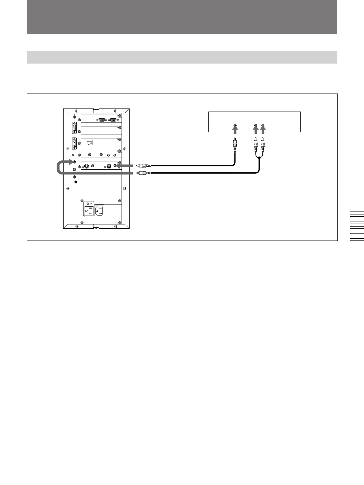
Sending Video Images and Sound to a Remote Party
Connecting Video Equipment
You can send video images (and/or sound) of a VCR connected to the
Rollabout Processor to a remote party.
Rollabout Processor
VMC-10/20/30 Connecting
cable (not supplied)
Use a YC-5V/10V/15V (not
supplied) when using an Svideo jack.
to VIDEO IN AUX 2
(to VIDEO IN AUX 1 when
using the S video jack)
to AUDIO IN AUX
Connecting with a VCR
VCR
to video
output
jack
to audio output jack
RK-C210/C220/C230
Connecting cable (not
supplied)
Chapter 4
Chapter 4 Operation of Optional Items 4-7
Page 82
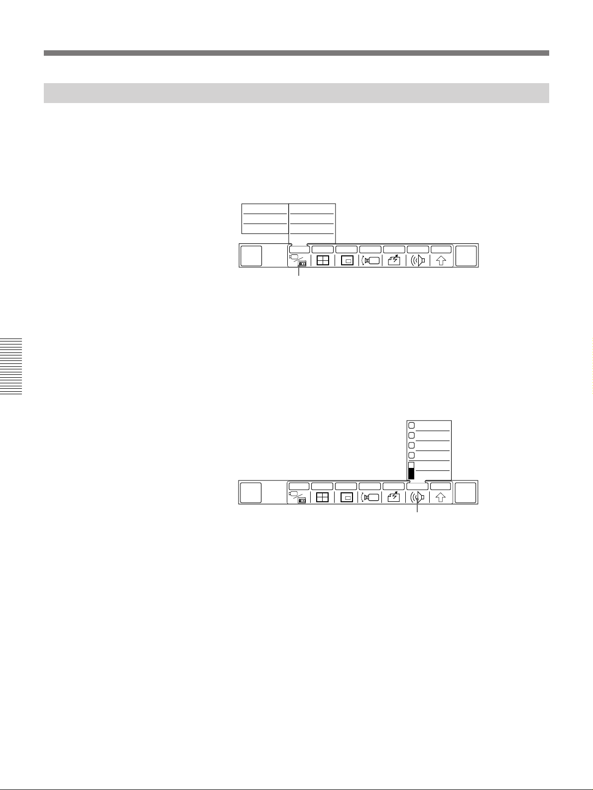
Sending Video Images and Sound to a Remote Party
Sending Video Image and Sound From a VCR
1 Turn on the VCR.
2 Play back a tape.
3 Select [INPUT] from the MAIN menu.
The INPUT sub-menu appears.
Chapter 4
FAR
AUX2
FAR
AUX1
FAR
MAIN CAM
QUICK
MENU
NEAR
AUX2
NEAR
AUX1
NEAR
MAIN CAM
SOURCE VIEW
MULTI P in P CAMERA SEND AUDIO OTHER
INPUT
[INPUT]
END OF
MEETING
4 Select the video source to send.
AUX1: to send an image from equipment connected to VIDEO IN
AUX 1 jack.
AUX2: to send an image from equipment connected to VIDEO IN
AUX 2 jack.
MAIN CAM: to send the image from local party’s camera.
5 Select [AUDIO] from the MAIN menu.
The AUDIO sub-menu appears.
MIC + AUX
AUX
MIC
MIC MUTE
VOL +
VOL –
MULTI P in P CAMERA SEND AUDIO OTHER
QUICK
MENU
INPUT
END OF
MEETING
4-8 Chapter 4 Operation of Optional Items
[AUDIO]
6 Select the audio source to send.
MIC+AUX: to send the sound from equipment connected to AUDIO
IN AUX jack and the local microphone (s).
AUX: to send the sound from equipment connected to AUDIO IN
AUX jack.
MIC: to send sound from the local microphone (s).
When you send the sound to a remote party, the sound is also output from
local TV monitor.
Page 83
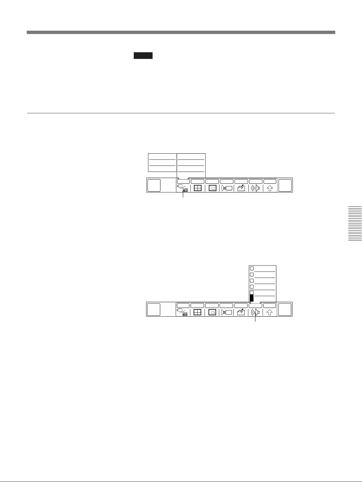
Notes
•When sending images from a VCR, we recommend you to use images
with slow movement. Scenes with rapid movement will appear fuzzy
when viewed by the remote party.
•The image sent may be distorted if you use special playback functions
such as pause.
To go back to the camera’s picture and sound
1 Select [INPUT] from the MAIN menu.
The INPUT sub-menu appears.
FAR
AUX2
FAR
AUX1
FAR
MAIN CAM
QUICK
MENU
NEAR
AUX2
NEAR
AUX1
NEAR
MAIN CAM
SOURCE VIEW
MULTI P in P CAMERA SEND AUDIO OTHER
INPUT
END OF
MEETING
[INPUT]
2 Select [NEAR MAIN CAM] from the INPUT sub-menu.
The picture of local party is sent again to the remote party.
3 Select [AUDIO] from the MAIN menu.
The AUDIO sub-menu appears.
MIC + AUX
AUX
MIC
MIC MUTE
VOL +
VOL –
MULTI P in P CAMERA SEND AUDIO OTHER
QUICK
MENU
INPUT
[AUDIO]
END OF
MEETING
Chapter 4
4 Select [MIC] from the AUDIO sub-menu.
The local party audio is sent again to the remote party.
5 Stop the playback.
Chapter 4 Operation of Optional Items 4-9
Page 84
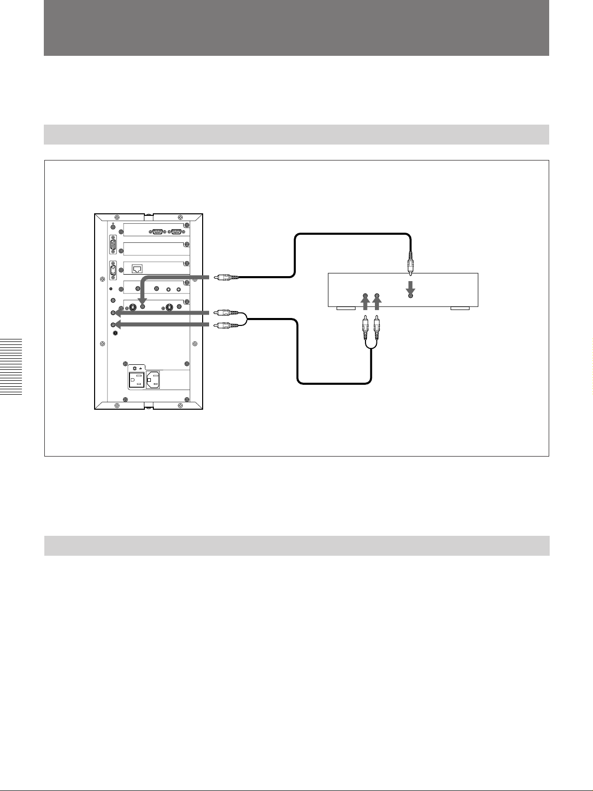
Recording a Meeting
You can record your meeting with a VCR.
Connect it to the Rollabout Processor.
Connecting a VCR
Rollabout Processor
to VIDEO OUT AUX
(to VIDEO OUT
MONITOR when
using the S-video
jack)
to AUDIO OUT
FAR/NEAR*
Chapter 4
Connecting a VCR (to record a videoconference)
VMC-10/20/30 Connecting cable (not supplied)
Use a YC-5V/10V/15V (not supplied) when using
an S-video jack.
VCR
to audio input jack
RK-C310/C320/C330 Connecting cable
(not supplied)
to video input jack
*On the Rollabout Processor, AUDIO OUT NEAR jack outputs the local party audio; AUDIO OUT FAR jack outputs the
remote party audio. When the VCR is connected as shown, the local party audio and the remote party audio are recorded on
separate channels.
Recording
4-10 Chapter 4 Operation of Optional Items
The Remote Commander cannot control the VCR. You must operate the
VCR directly to start and stop recording.
Recording checklist
•Make sure the VCR is connected properly to the Rollabout Processor.
•Make sure the input setting on the VCR is set properly.
•Make sure a videotape is inserted into the VCR.
Page 85
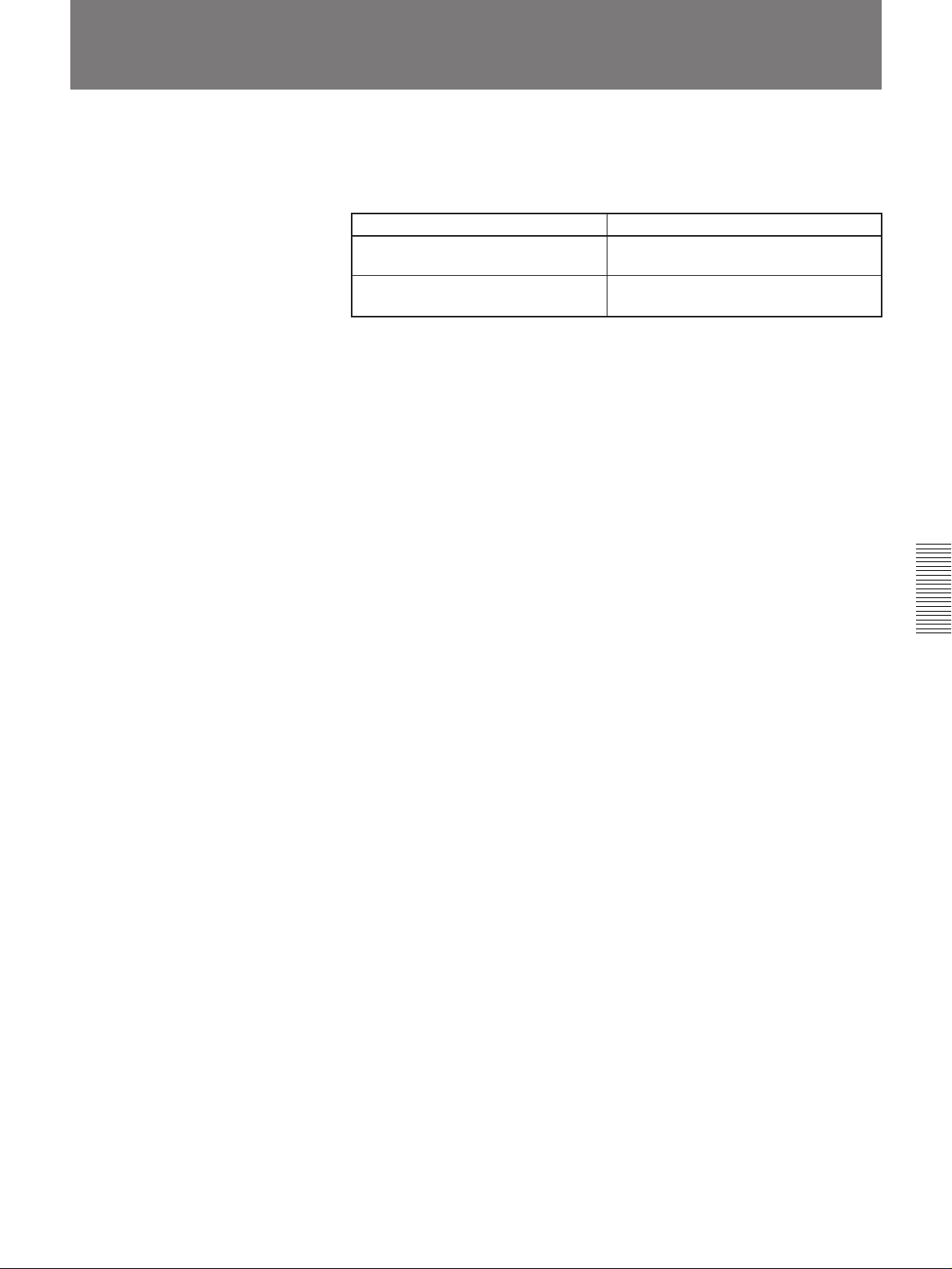
Installing Optional Interface Boards
If you want to connect your Rollabout Processor via the V.35 interface or
via two ISDN lines, you need to install an interface board.
For details on installing the optional boards, consult with qualified Sony dealer.
Application Board required
Making a connection via a V.35 line PCS-I500 V.35 Interface board
interface
Making a connection via two BRI PCS-I300 BRI Board
interface
Chapter 4
Chapter 4 Operation of Optional Items 4-11
Page 86
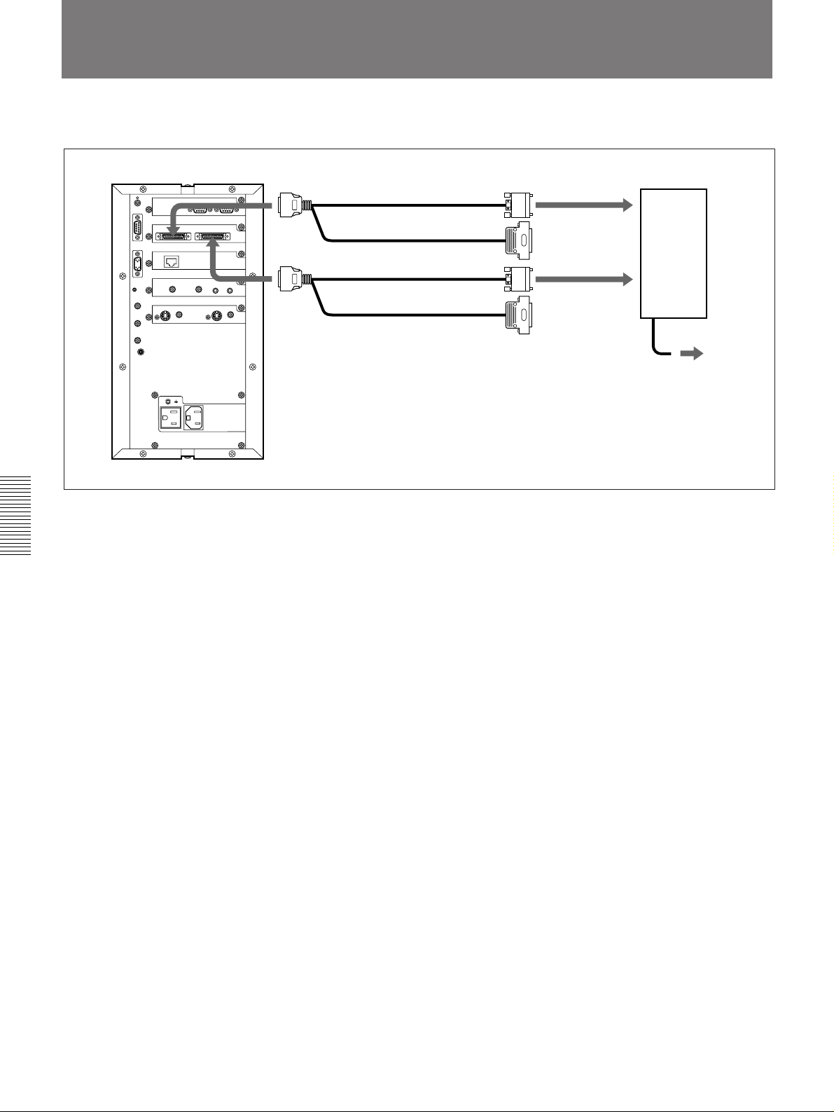
Using the V.35 Interface
You need to install the PCS-I500 V.35 interface board (not supplied).
Chapter 4
Rollabout Processor
to V.35A
to V.35B
PCS-K32 V.35 cable
(1m, 3.3 ft (not supplied))
to Channel A
to Channel B
PCS-K32 V.35 cable
(1m, 3.3 ft (not supplied))
* For 56 Kbps × 2 or 64 Kbps × 2, connect to Channels A and B. For 56 – 384 Kbps,
connect to Channel A.
Connecting to a digital line using a V.35 interface
Terminal adapter
to a digital
line
4-12 Chapter 4 Operation of Optional Items
Page 87
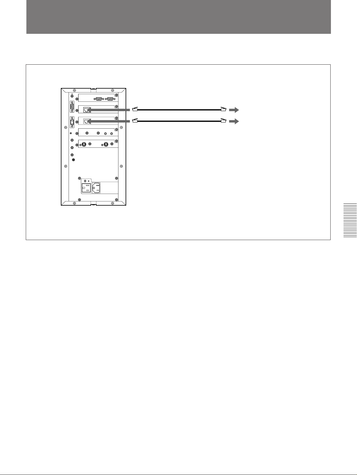
Using Two ISDN Lines
You need to install the PCS-I300 BRI Board (not supplied).
Rollabout Processor
to ISDN B
Second ISDN modular cable (3 m, 9.8 ft)
RK-640 Interface cable (not supplied)
to ISDN
to ISDN A
Connection using two ISDN lines
First ISDN modular cable (3 m, 9.8 ft)
(PCS-3000P: supplied)
(PCS-3000: not supplied)
Chapter 4
Chapter 4 Operation of Optional Items 4-13
Page 88
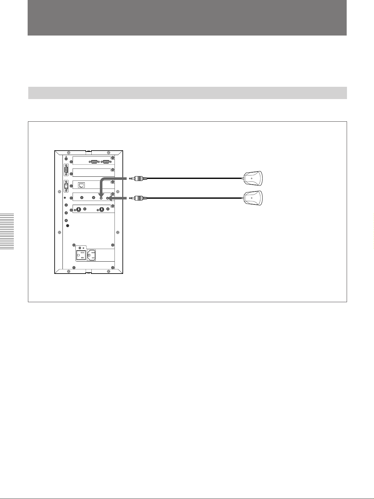
Using Multiple Microphones
The PCS-3000/3000P Rollabout Package is designed to accommodate
three participants per terminal. You can add additional PCS-A300
Microphone (not supplied) to allow for more participants.
Connecting Second Microphone
The second microphone’s power is provided from the Rollabout Processor.
Rollabout Processor
Chapter 4
to AUDIO MIC 1
to AUDIO MIC 2
Connecting second microphone
(supplied)
PCS-A300 Microphone
(not supplied)
4-14 Chapter 4 Operation of Optional Items
Page 89
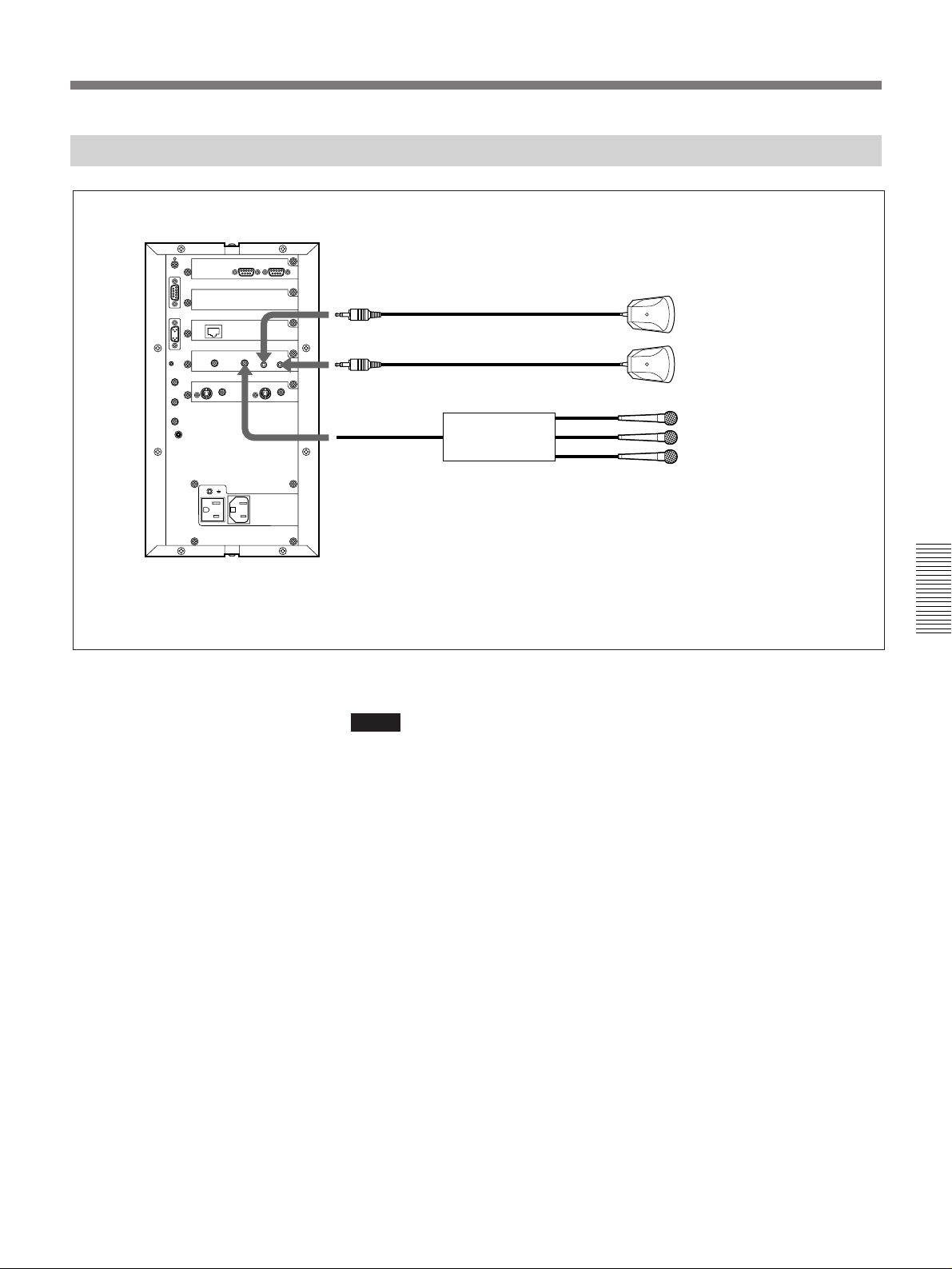
Connecting the Multiple Microphones via the Audio Mixer
Rollabout Processor
to AUDIO MIC 1
to AUDIO MIC 2
to AUDIO LINE
IN
Connecting the audio mixer
(supplied)
PCS-A300 Microphone
(not supplied)
Audio mixer
Microphone
Microphone
Microphone
Notes
•Use the SRP-X1008 Audio Mixer or equivalent one.
•Do not connect the PCS-A300 Microphone or a plug in power type
microphone to the audio mixer.
•If you have any problem, consult with qualified Sony personnel.
Chapter 4
Chapter 4 Operation of Optional Items 4-15
Page 90
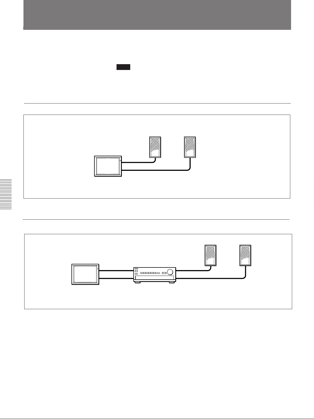
Connecting the Speakers to the Monitor
If you use a monitor which does not have speakers, connect the active
speakers or an amplifier and speakers to your monitor.
Note
Do not activate the function of the speakers or an amplifier, such as the
surround function. Otherwise, the sound from the speaker is strange since
the echo canceller on the Rollabout Processor does not function correctly.
When using the active speakers
Active speakers
Monitor
to audio output
jacks
Chapter 4
When using the amplifier and speakers
to
Monitor
audio
output
jacks
Connecting the active speakers
to
audio
input
jacks
Amplifier
Connecting the amplifier and speakers
to speaker
terminals
Speakers
4-16 Chapter 4 Operation of Optional Items
Page 91
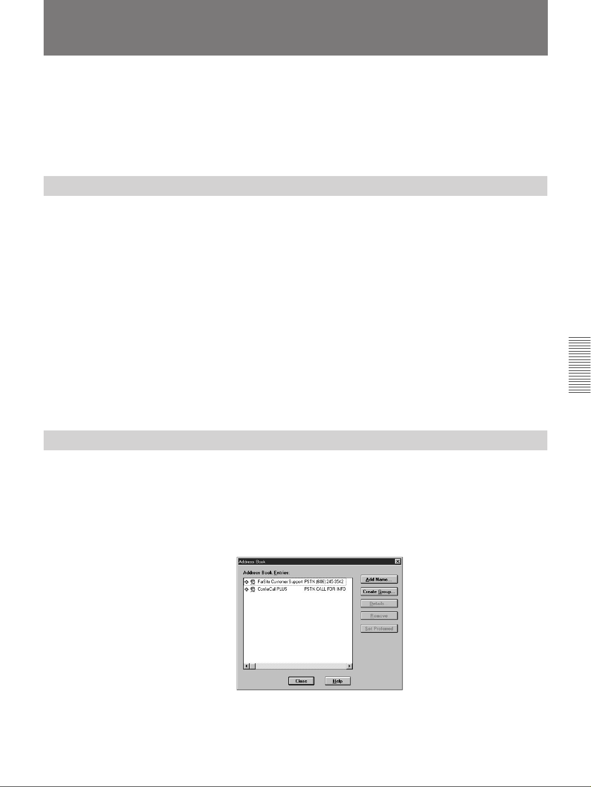
Preparing for a Data Conference
You can have a data conference based on an ITU-T Recommendation,
T.120 standard when you connect a computer which FarSite (not supplied)
or NetMeeting
data conference is only held between same applications.)
For details on information about FarSite
supplied with the FarSite package.
Installing FarSite
Insert the FarSite disk #1 in your floppy drive and start Setup. exe. Follow
the procedure on “2 Installation” in USER’S GUIDE supplied with the
FarSite package.
The following describes only the notes on installation.
•Type the serial number in the column of the [Serial Number] in the
[FarSite 3.0 Registration] dialog box.
The serial number is the last 10 digits of REG# on the FarSite package.
•When you set up the Com ports on your PC, set [Flow Control] to
[Hardware].
•When you set the [FarSite Communications Wizard] dialog box:
– click on the [Install Modem (s) for FarSite] check box, then click on
[Next] at the step 1.
– select the Com port to use and [Null Modem], then click on [Next] at
the step 2.
– click on [Finish] at the step 3.
1)
(not supplied) is installed with the Rollabout Processor. (A
2)
, refer to the USER’S GUIDE
Chapter 4
Setting Up FarSite
1 Turn on your PC and start Windows.
2 Select [FarSite 3.0] from the Start pop-up menu (for Windows 95
3)
click on the FarSite icon (for Windows 3.1
).
3)
) or
3 Select [Address Book] from the [Conference] menu.
The following screen appears.
(Continued)
......................................................................................................................................................................................
1) NetMeeting is registered trademarks of the Microsoft corporation.
2) FarSite is a registered trademark of the DataBeam corporation.
3) Windows95 and Windows3.1 are registered trademarks of the Microsoft corporation.
Chapter 4 Operation of Optional Items 4-17
Page 92
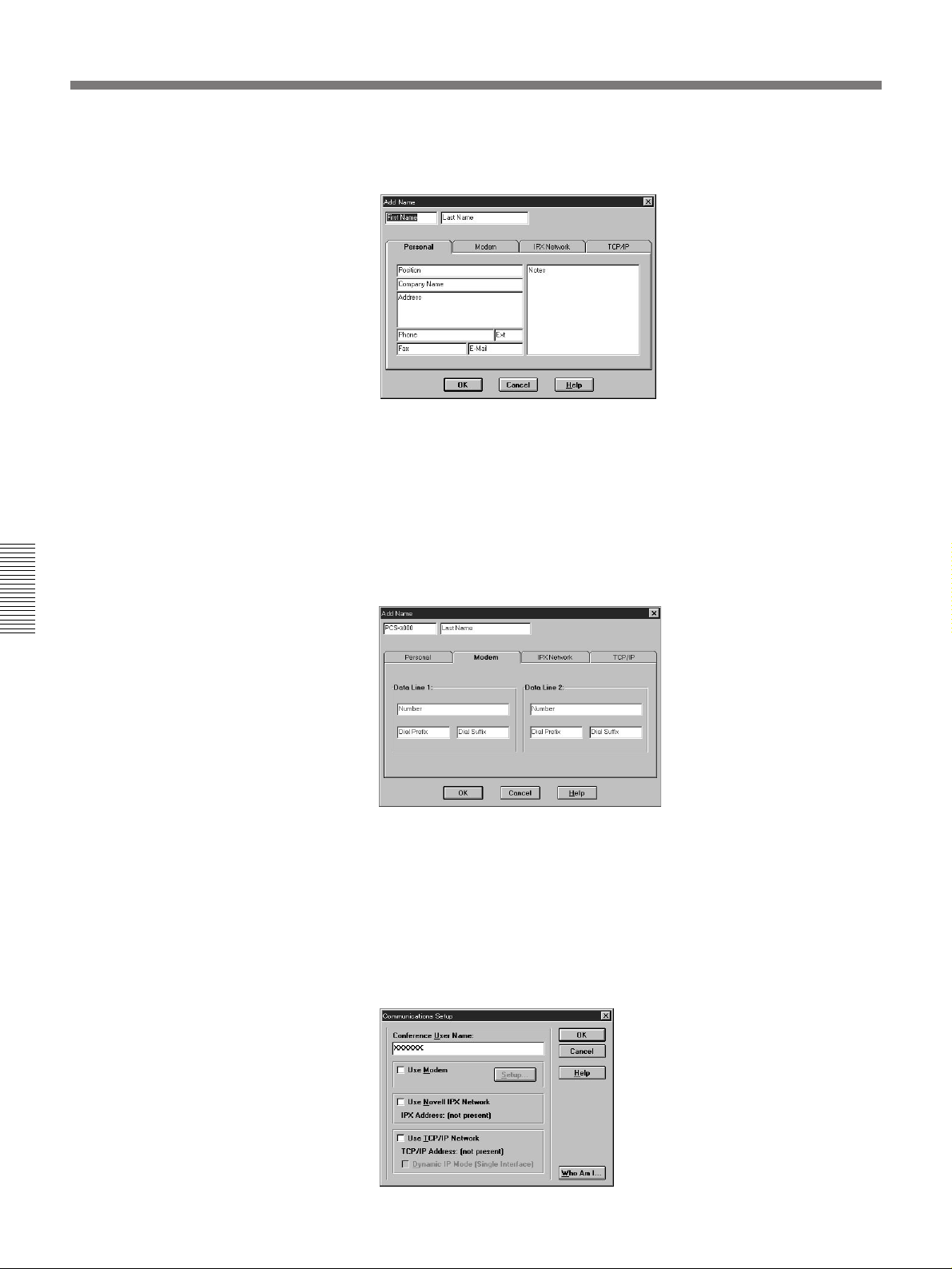
Preparing for a Data Conference
4 Click on the [Add Name] button.
The [Add Name] dialog box appears.
5 When using PCS-3000
Click on the [Personal] tab, then type “PCS-3000” in the column of
[First Name].
When using PCS-3000P
Click on the [Personal] tab, then type “PCS-3000P” in the column of
[First Name].
Chapter 4
6 Click on the [Modem] tab.
The [Modem] dialog box appears.
7 Type “NULL” in the column of [Data Line 1: Number].
8 Click on [OK].
9 Click on [Close].
10Select [Communications Setup] from the [Conference] menu.
The following screen appears.
4-18 Chapter 4 Operation of Optional Items
Page 93
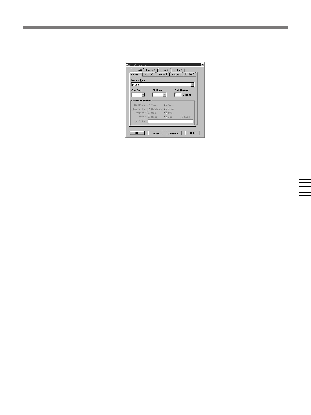
11Click on the [Setup] button.
The [Setup] dialog box appears.
12Set up the bit rate.
•Set the bit rate to 9600 or 38400 according to your T. 120 rate.
•Check that [Stop Bits] is set to [One] and [Parity] is set to [None].
13Set [Flow Control] to [Hardware] in [Advanced Options].
14Click on [OK].
15Click on [Close].
The setting is complete, and the original screen appears.
Chapter 4
Chapter 4 Operation of Optional Items 4-19
Page 94
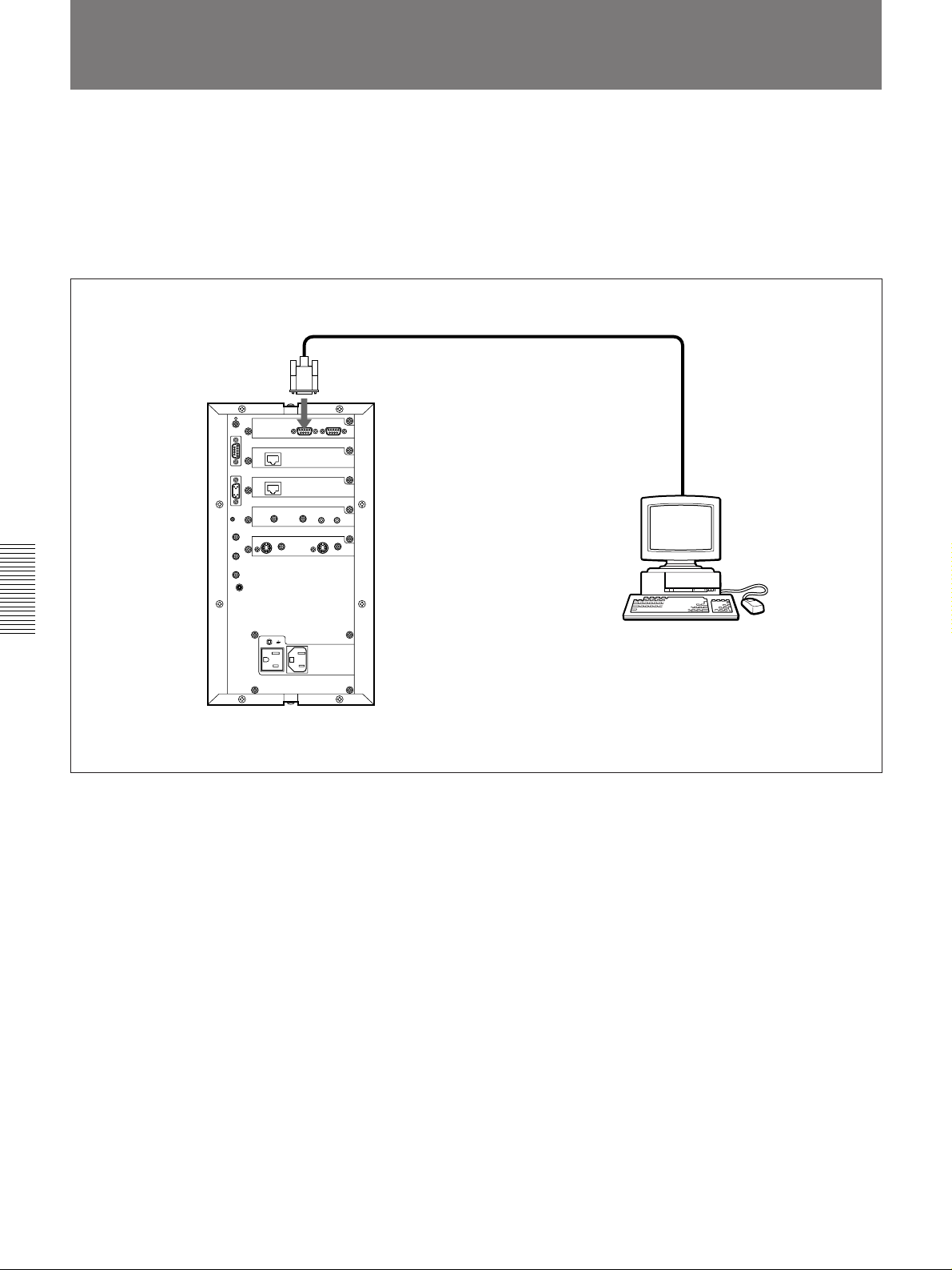
Connecting with a Computer
Connect the serial port Com1 of your PC and the T.120 connector on the
Rollabout Processor using the RS-232C cross cable (9-pin (female) ˜ 9pin (female)). When the Com1 port is used with such as a mouse, connect
to Com2 port and change the Com port setting of the FarSite.
For details on changing the setting of the FarSite, refer to the USER’S GUIDE
supplied with the FarSite package.
to T.120 connector
to Com1 or Com2 port
Chapter 4
Computer
Rollabout Processor
4-20 Chapter 4 Operation of Optional Items
Page 95
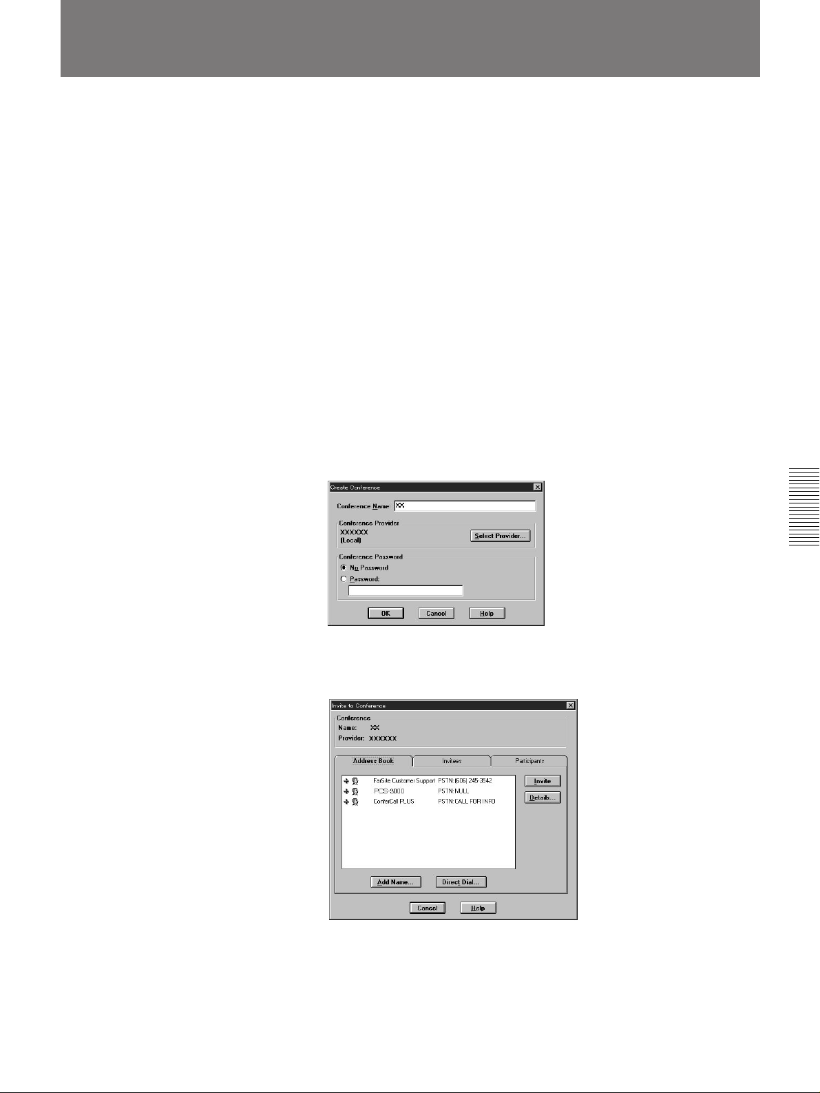
Using FarSite
Notes on using T.120
You cannot use the following functions:
•Multi meeting function
•Controlling the camera unit at a remote site
•Setting H.281.
For details on FarSite, refer to the USER’S GUIDE supplied with FarSite
package.
1 Turn on your PC and start Windows.
2 Select [FarSite 3.0] from the Start pop-up menu (for Windows 95) or
click on the FarSite icon (for Windows 3.1).
3 Start a meeting with a remote party.
4 Determine which terminal is used for holding a meeting.
5 Select [Create] from [Conference] menu at the inviter of the meeting
side.
The following screen appears.
6 Type a new name, such as a remote party’s name, in the column of
the [Conference Name] and click on [OK].
The [Invite to Conference] dialog box appears.
Chapter 4
(Continued)
Chapter 4 Operation of Optional Items 4-21
Page 96
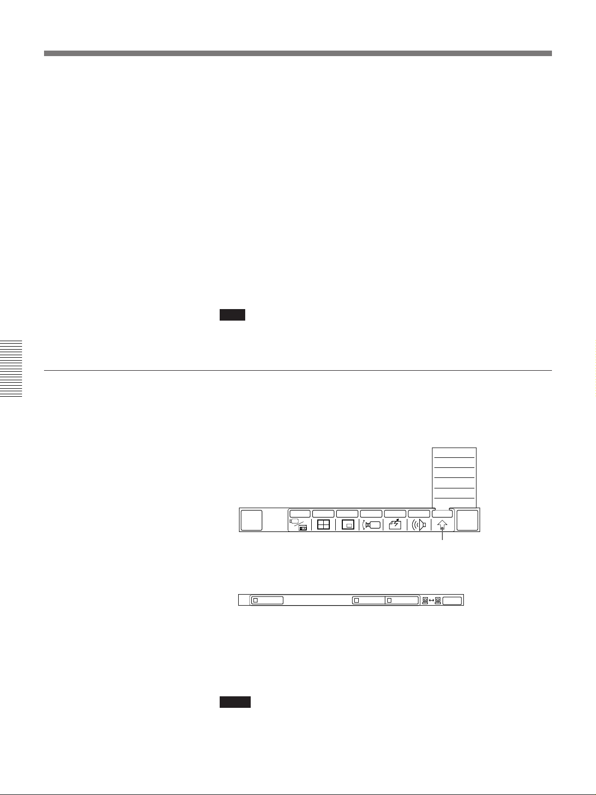
Using FarSite
7 When using PCS-3000
Double click on “PCS-3000”, then click on the [Invite] button.
When using PCS-3000P
Double click on “PCS-3000P”, then click on the [Invite] button.
“? You are being invited to a conference called xxxx. Would you like
to attend?” message appears on the monitor at remote users. Then
remote users click on [Yes], the [PCS-XXXX PSTN: NULL Waiting
for response] indication changes to [PCS-XXXX PSTN: NULL
Accepted].
8 Click on [Close].
9 Select [Share Workbook] and [Share Application] from the
[Conference] menu.
The data conference can be held now.
Note
There may be connected in a different rate or not able to be connected
depending on the remote parties’condition of the line or terminal.
To check the T.120 rate
Chapter 4
If the indication does not appear in step 7, do the following operation to
change the T.120 rate of the FarSite after checking the T.120 rate.
1 Select [OTHER] from the MAIN menu.
The sub-menu appears.
QUICK
MENU
INPUT MULTI P in P CAMERA SEND AUDIO OTHER
SETUP
STATUS
DTMF
T.120
DIAL LIST
MANUAL DIAL
[OTHER]
END OF
MEETING
2 Select [T.120].
The status of the T.120 rate is indicated.
OFF
384009600
EXIT
3 Select [EXIT].
The MAIN menu appears.
For details on changing the transmission rate of the FarSite, refer to the USER’S
GUIDE supplied with the FarSite package.
4-22 Chapter 4 Operation of Optional Items
Notes
•The T.120 rate indicated in the Rollabout Processor is the transmission
rate between the Rollabout Processor and the PC. The actual T.120 rate is
slower than the rate between Rollabout Processor and the PC.
•Operating speed may be reduced depending on the condition of the line.
Page 97

To hold a data conference through the MCU
1 Reserve at the MCU and confirm the Conference Name.
2 Connect with the MCU.
3 Select [Join] from the [Conference] menu.
4 When using PCS-3000
Double click on “PCS-3000”, then click on the [Join] button.
When using PCS-3000P
Double click on “PCS-3000P”, then click on the [Join] button.
5 Type the Conference Name and double click on [OK].
Note on the Conference Name
The Conference Name is consists of the “Conference_name” and “ID
number.”
The Conference Name is as follows:
•When the “Conference_name” is “test” and “ID number” is “77”:
Conference Name is “test-77.”
•When the “Conference_name” is none and “ID number” is “77”:
Conference Name is “-77.”
Chapter 4
Chapter 4 Operation of Optional Items 4-23
Page 98
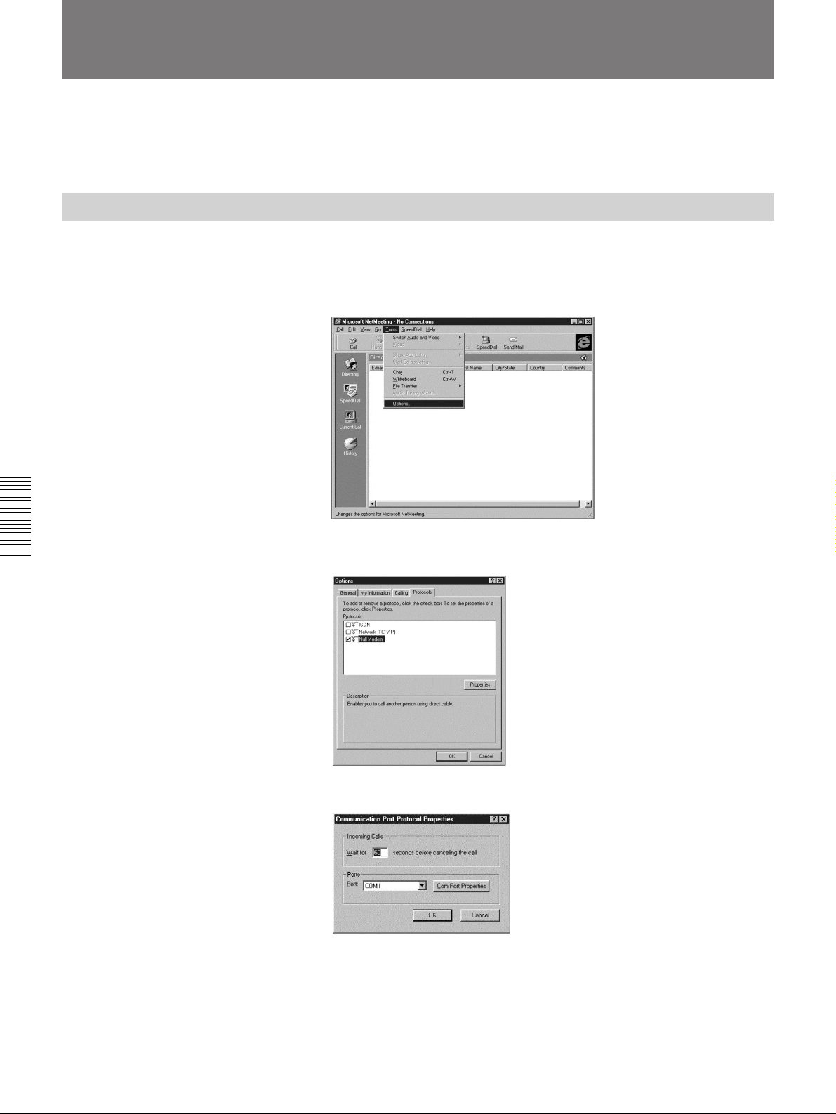
Using NetMeeting
Setting Up NetMeeting
To install NetMeeting
Follow the procedures explained by the NetMeeting file to install
NetMeeting to your PC.
1 Select [NetMeeting] from the Start pop-up menu or click on the
NetMeeting icon.
2 Select [Option] from the [Tools] menu.
Chapter 4
3 Click on the [Protocols] tab, then click on “Null Modem.”
4 Click on the [Properties] button, then select the COM port to be used.
4-24 Chapter 4 Operation of Optional Items
Page 99
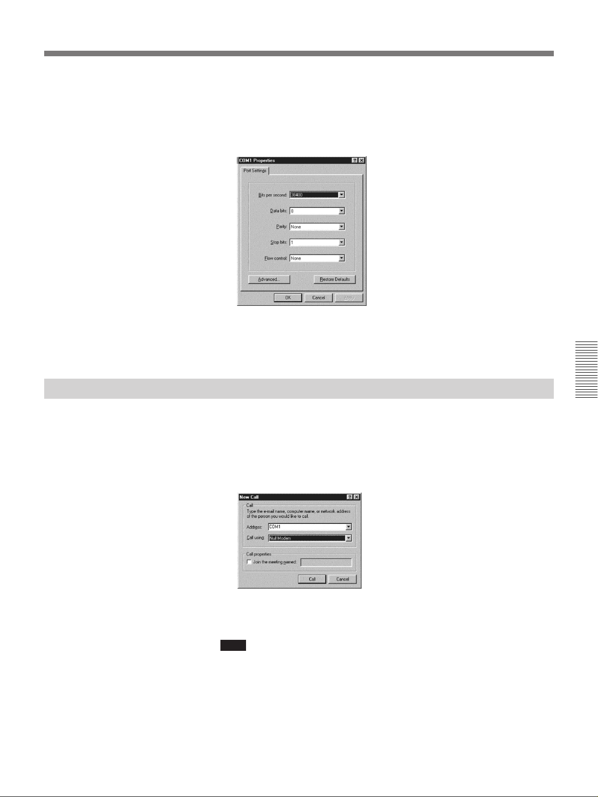
5 Click on the [Properties] button, then select the transfer rate to be used.
When the T.120 rate is set to 38.4K, select 38400 and the T.120 rate is
set to 9.6K, select 9600.
Check that the following settings:
Data bits : 8, Parity : None, Stop bit : 1, Flow control : None
6 Click on the [OK] button repeatedly until the menu returns to its first
one.
Connecting With NetMeeting
1 Set the Rollabout Processor to be on line.
2 Click on [Calling] at both local and remote.
3 Set [Address] in the [New call] dialog box to COM1 or COM2, and
[Call Using] to NULL Modem.
Soon, the connection is established.
Note
When connecting both PCS-3000/3000Ps, you can start a meeting from
both sides by clicking on [New Call]. But when the remote party
equipment is other companies equipment, the connection may be failed if
PCS-3000/3000P clicks on [New Call] first. In such cases, first click on
[New Call] from the remote party.
Chapter 4
Click on the [Call] button.
Chapter 4 Operation of Optional Items 4-25
Page 100
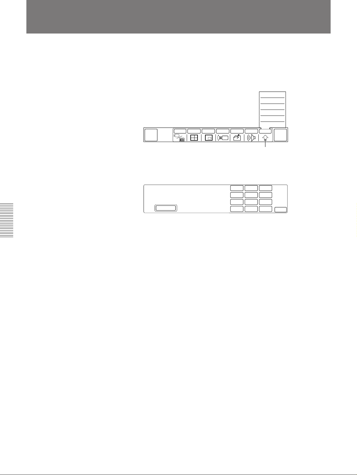
Sending the Dial Tone to the Remote Party
You can send the dial tone (Dual Tone Multi Frequency) assigned to 0 – 9,
# and * keys, to the remote party
1 Select [OTHER] from the MAIN menu and select [DTMF].
SETUP
STATUS
DTMF
USER DATA
DIAL LIST
MANUAL DIAL
QUICK
DIAL
2 Select the key number to be sent.
The selected dial tone is sent to the remote party.
INPUT MULTI P in P CAMERA SEND AUDIO OTHER
MENU OFF
[OTHER]
1
2
3
4
5
6
7
8
9
∗
0
#
END OF
MEETING
EXIT
Chapter 4
To go back to the MAIN menu
Select [EXIT].
To clear the menu
Select [MENU OFF].
4-26 Chapter 4 Operation of Optional Items
 Loading...