

Page 1
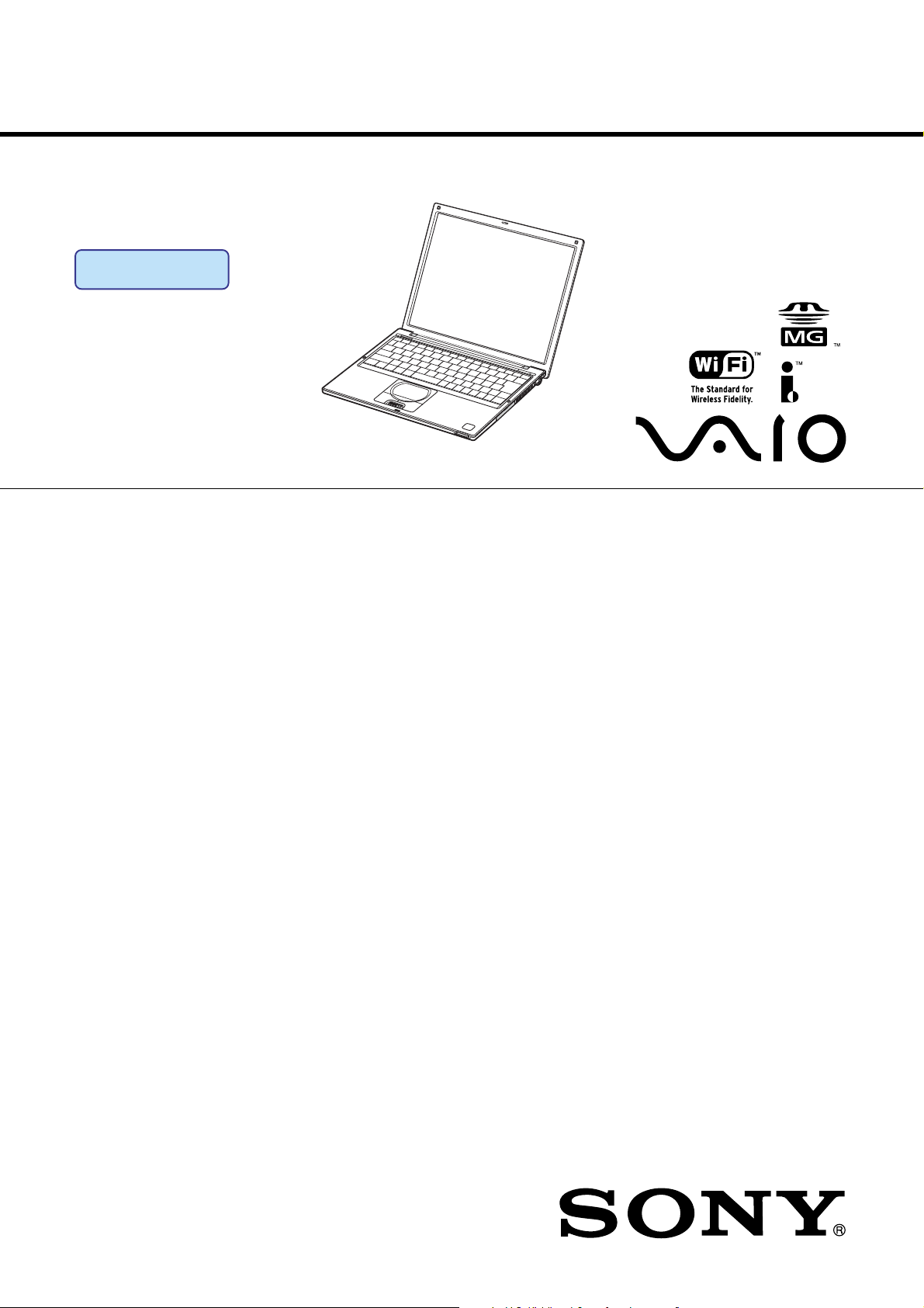
PCG-VX89/VX89K/VX89P
SERVICE MANUAL
Ver 1-2002J
Revision History
Lineup : PCG-VX89P
PCG-VX89K
PCG-VX89
Illust : PCG-VX89P
For American Area
US Model
Canadian Model
S400
Confidential
• Design and specifications are subject to
change without notice.
9-876-021-01
NOTEBOOK COMPUTER
Page 2
Information in this document is subject to change without notice.
Sony, VAIO and CLIE are trademarks or registered trademarks of
Sony. Microsoft, Windows, Windows Media, Outlook, Bookshelf
and other Microsoft products are trademarks or registered trademarks
of Microsoft Corporation in the United States and other countries.
The word Bluetooth and the Bluetooth logo are trademarks of
Bluetooth SIG, Inc. AMD, AMD logo, AMD Duron and
combinations thereof, 3DNow!, are trademarks of Advanced Micro
Devices, Inc. Intel Inside logo, Pentium and Celeron are trademarks
or registered trademarks of Intel Corporation. Transmeta, the
Transmeta logo, Crusoe Processor, the Crusoe logo and
combinations thereof are trademarks of Transmeta Corporation in
the USA and other countries. Graffiti, HotSync, PalmModem, and
Palm OS are resistered trademarks, and the Hotsync logo and Palm
are trademarks of Palm, Inc. or its subsidiaries. (M) and Motrola
are trademarks of Motrora, Inc. Other Motrola products and services
with (R) mark like Dragomball are the trademarks of Motrola, Inc.
All other names of systems, products and services in this manual
are trademarks or registered trademarks of their respective owners.
In this manual, the (TM) or (R) mark are not specified.
Caution Markings for Lithium/Ion Battery - The following or similar
texts shall be provided on battery pack of equipment or in both the
operating and the service instructions.
CAUTION: Danger of explosion if battery is incorrectly replaced.
Replace only with the same or equivalent type recommended by
the manufacturer. Discard used batteries according to the
manufacturer’s instructions.
CAUTION: The battery pack used in this device may present a fire
or chemical burn hazard if mistreated. Do not disassemble, heat
above 100°C (212°F) or incinerate.
Dispose of used battery promptly.
Keep away from children.
CAUTION: Changing the back up battery.
• Overcharging, short circuiting, reverse charging, multilation or
incineration of the cells must be avoided to prevent one or more of
the following occurrences; release of toxic materials, release of
hydrogen and/or oxygen gas, rise in surface temperature.
• If a cell has leaked or vented, it should be replaced immediately
while avoiding to touch it without any protection.
Service and Inspection Precautions
1. Obey precautionary markings and instructions
Labels and stamps on the cabinet, chassis, and components identify areas
requiring special precautions. Be sure to observe these precautions, as well
as all precautions listed in the operating manual and other associated
documents.
2. Use designated parts only
The set’s components possess important safety characteristics, such as
noncombustibility and the ability to tolerate large voltages. Be sure that
replacement parts possess the same safety characteristics as the originals.
Also remember that the 0 mark, which appears in circuit diagrams and
parts lists, denotes components that have particularly important safety
functions; be extra sure to use only the designated components.
3. Always follow the original design when mounting
parts and routing wires
The original layout includes various safety features, such as inclusion of
insulating materials (tubes and tape) and the mounting of parts above the
printer board. In addition, internal wiring has been routed and clamped so
as to keep it away from hot or high-voltage parts. When mounting parts or
routing wires, therefore, be sure to duplicate the original layout.
4. Inspect after completing service
After servicing, inspect to make sure that all screws, components, and wiring
have been returned to their original condition. Also check the area around
the repair location to ensure that repair work has caused no damage, and
confirm safety.
5. When replacing chip components...
Never reuse components. Also remember that the negative side of tantalum
capacitors is easily damaged by heat.
6. When handling flexible print boards...
• The temperature of the soldering-iron tip should be about 270C.
• Do not apply the tip more than three times to the same pattern.
• Handle patterns with care; never apply force.
Caution: Remember that hard disk drives are easily damaged by
vibration. Always handle with care.
ATTENTION AU COMPOSANT AYANT RAPPORT
À LA SÉCURITÉ!
LES COMPOSANTS IDENTIFÉS PAR UNE MARQUE 0 SUR LES
DIAGRAMMES SCHÉMATIQUES ET LA LISTE DES PIÈCES SONT
CRITIQUES POUR LA SÉCURITÉ DE FONCTIONNEMENT. NE
REMPLACER CES COMPOSANTS QUE PAR DES PIÈSES SONY
DONT LES NUMÉROS SONT DONNÉS DANS CE MANUEL OU
DANS LES SUPPÉMENTS PUBLIÉS PAR SONY.
— 2 —
Confidential
PCG-VX89/VX89K/VX89P (AM)
Page 3

TABLE OF CONTENTS
Section Title Page
CHAPTER 1. BLOCK DIAGRAM ............................... 1-1
(to 1-2)
CHAPTER 2. FRAME HARNESS DIAGRAM ........ 2-1
(to 2-2)
CHAPTER 3. EXPLODED VIEWS AND
PARTS LIST............................................ 3-1
3-1. Main Section .................................................................... 3-2
3-2. LCD Section – Made by HI – .......................................... 3-5
(to 3-6)
History of the changes is shown as the
“Revision History” at the end of this data.
— 3 —
Confidential
PCG-VX89/VX89K/VX89P (AM)
Page 4
CNX -176
RJ-45
VGA CN
CN15P
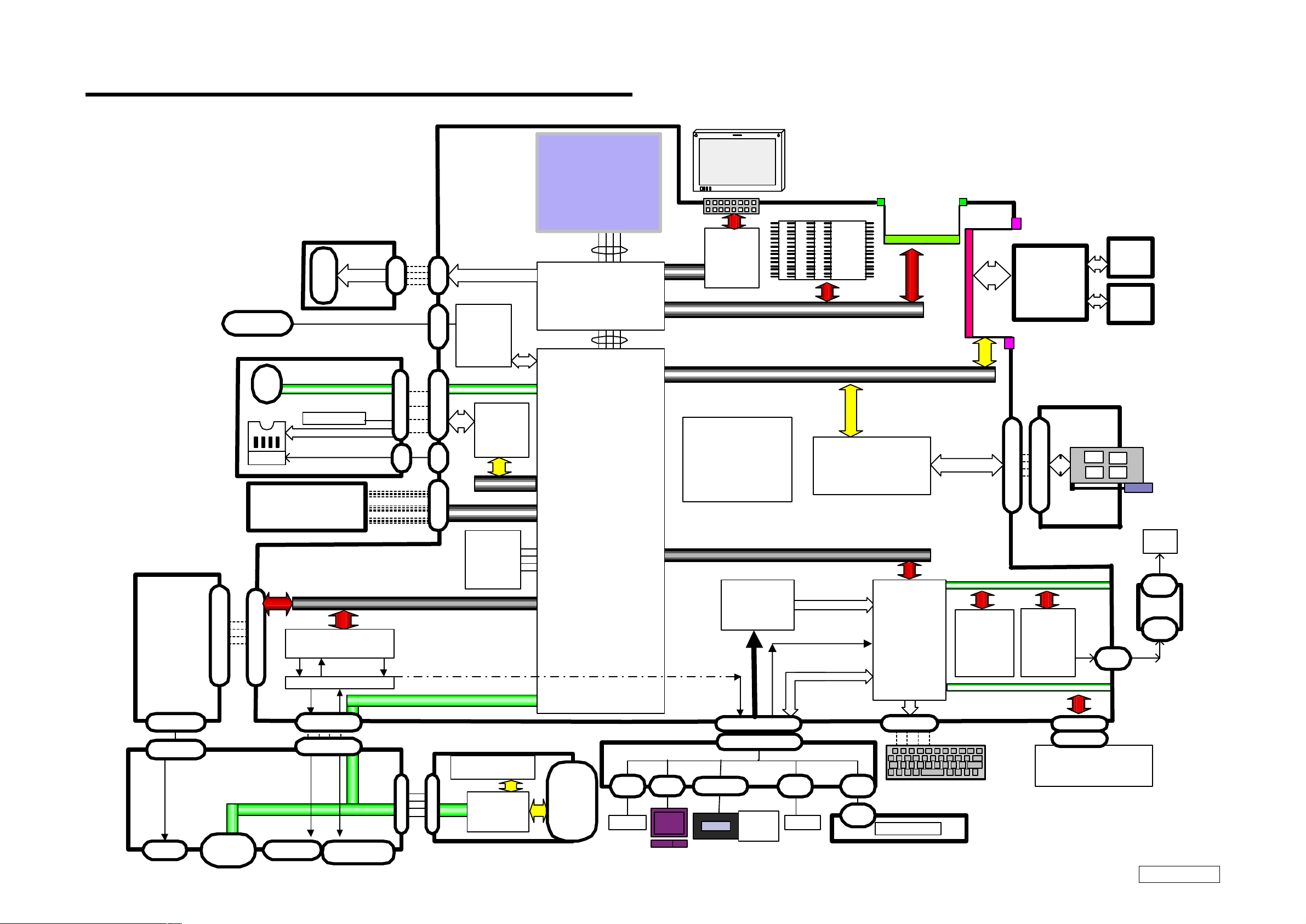
CHAPTER 1.
BLOCK DIAGRAM
14.1XGA
Intel Pentium
III
-m
90 0MHz
LV
30p
DV 0
CN
15 P
CN
15 P
Intel 82815EM-T
CN 4 P
Intel
DA82562ET
GMCH2-m
Memory Bus PC=100
LCD &
Inverter
SONY
VCH
Intel /
FW82807A
A
1
256MB Tech
256MB DIMM
W-LAN
MiniPCI
Module
Type
III
IFX-209( Left)
Ant L
(Sub)
Ant R
(Main)
IFX-208(Right)
CNX -173
MODEM
Conexant
Smart MC2
USB CN
CN4P
i .LINK
USB 1 . 1
W-LAN SW
USB 1 . 1
CN 17 P
CN 17 P
i.Link
PCI Bus
Mini P CI
Connector
TypeIII
TSB43AB
CN 10 0 P
CN 10 0 P
DC out
Ultra ATA66/100
HDD
2P
CN
2P
CN 50 P
CN
PCI
22
Clock Generator
IMI/C9835AT
CardBus/16bitCard
Card con troller
RICOHR5C475II
MBX-56
Intel 82801BAM
FWH
SST
ICH2-m
LPC Bus
PC Card Connector
1 Slot
49LF004A
JogDial
CN 30P
CN 30P
AC Link
Audio Codec
(AC '97)
Amp
USB 1 . 1
Encoder
KBC/EC
HITACH
H8/2149
I/ O
Expander
O2MICRO
OZ99 8S
ATF
AD1030A
CN
2P
FAN
CN
2P
CN
3P
FLT-7
CN 2 P
CN 2 P
RJ 1 1
CNX-174
USB C N
CN4P
USB 1 . 1
MIC CN
CN 30 P
CN 30 P
HeadPhone
1
CN
STmicr o
M29W200BB70N6
Memorystick
CN 14 P
CN 14 P
USB 1 . 1
Memoryst ick
Controller
Slot
IFX -207
CN
2P
SP(L )
CN
12 P
TouchPad
CN 7 P
JOG
CN 30 P CN24P
CN 30 P
Back
Botto n
CN
2P
SP(R )
SWX-101
CN
8P
CN
8P
Ke y B oard
Power SW
SWX-103
CN6P
CN6P
Battery
11.1V/3600mAh
Confidential
1-21-1
(END)
PCG-VX89/VX89K/VX89P (AM)
Page 5
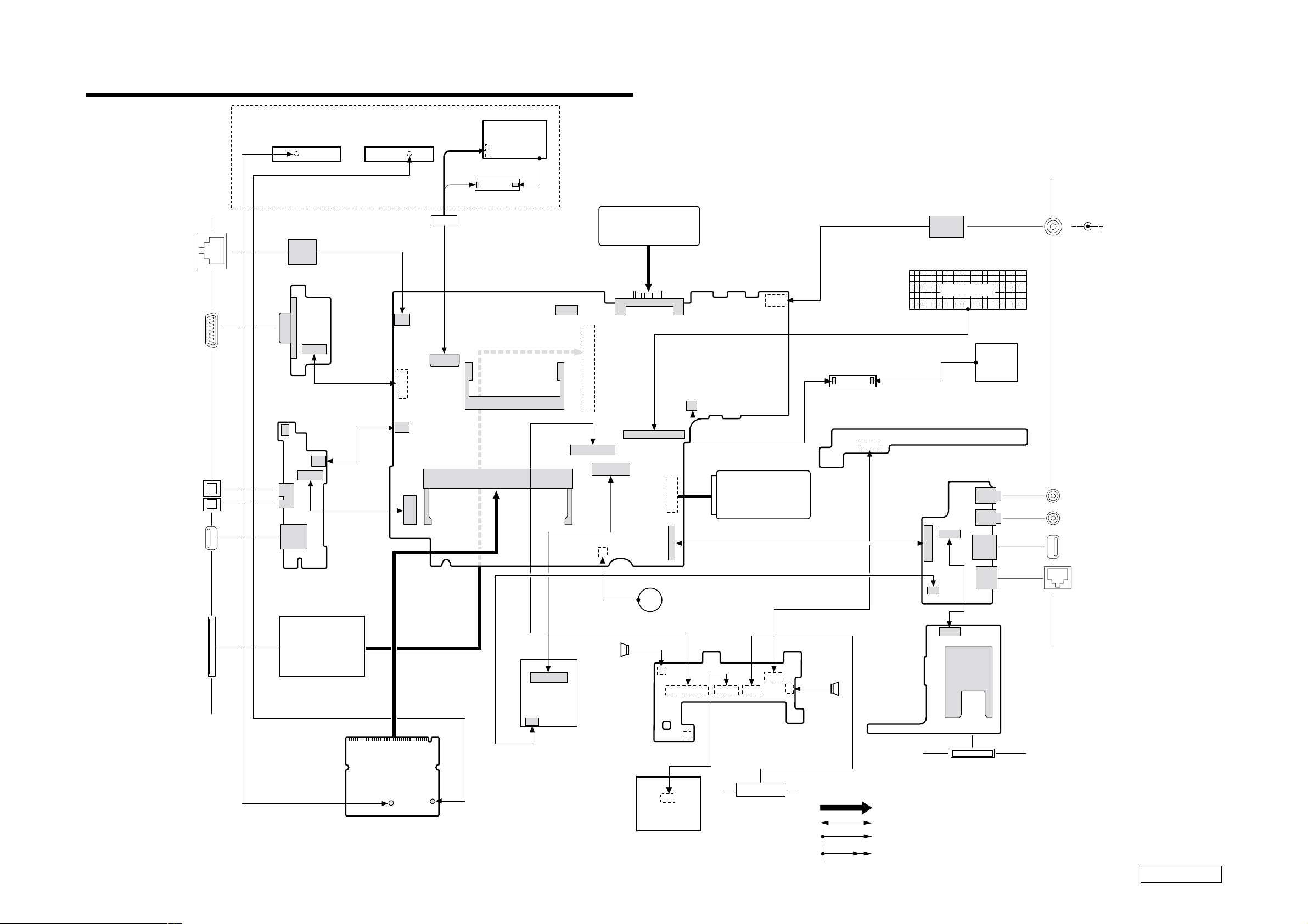
CHAPTER 2.
FRAME HARNESS DIAGRAM
NETWORK
DISPLAY
IEEE 1394 i.LINK
DC OUT
USB
L Side
IFX-209 Board
(Side-A)
CN8200
HARNESS, RJ-45
CN5001
15 1
CNX-176 Board
(Side-A)
CN4000
2
1
1
CN4001
CN4002
CN4003
CNX-173 Board
(Side-A)
IFX-208 Board
(Side-A)
CN8100
LCD HARNESS
14
CN1700
20
CN1001
15
19
CN1000
1
1
2
CN1410
123
CN1400
124
1
17
2
1
2
1
LCD
INVERTER
CN800
CN2100
LCD Block
2
30
1
29
CN2600
1
144
99
143
CN1901
1
2
2
CN1301
100
2
1
CN2500
21
BATTERY PACK
61
CN2502
23
24
CN1800
130
30
21
29
CN1500
CN2000
50 49
29 30
CN2602
12
NICKEL HYDROGEN
MBX-56 Board
(Side-A)
CN300
12
1
2
BATTERY
1
2
CN2501
HARD DISK
FLT-7 Board
(Side-A)
CN1
CN2
CN6500
HARNESS, (WITH DC JACK)
KEY BOARD
DC FAN
SWX-103 Board
(Side-A)
CNX-174 Board
(Side-A)
1
CN4699
CN4503
114
30
CN4600
CN4500
CN4502
CN4501
CN4601
R Side
DC IN
EXTERNAL MIC IN
HEADPHONE
USB
PHONE
PC CARD
PC CARD
CONNCTOR
CARD, WIRELESS LAN
2
211
J1
CON2
30
29
CARD, MODEM
SPEAKER
LEFT
CN6001
CN6004
12 1
J1
PAD, TOUCH
CN6005
CN6002
18
1
12130 17
CN6003
SWX-101 Board
(Side-A)
DIAL UNIT, JOG
CN6000
SPEAKER
RIGHT
CN5500
14 1
IFX-207 Board
(Side-A)
Front Face
MEMORY STICK
From board to connector (direct connection)
Harness (connector at both end)
Harness (soldered at one end)
Connectors soldered on board and appearing on the panel
2-22-1
(END)
PCG-VX89/VX89K/VX89P (AM)
Confidential
Page 6

EXPLODED VIEWS AND PARTS LIST
NOTE:
• Items marked “ * ” are not stocked since they are seldom
required for routine service. Some delay should be
anticipated when ordering these items.
• The mechanical parts with no reference number in the
exploded views are not supplied.
• When two or more parts are shown in parallel, use the
part described first as the main part.
• The parts marked “ $ ” are the High Value Modules.
• The parts marked “ # ” are the parts on which
barcode label is attached.
CHAPTER 3.
The components identified by mark 0 or
dotted line with mark 0 are critical for safety.
Replace only with part number specified.
Les composants identifiés par une marque
0 sont critiques pour la sécurité.
Ne les remplacer que par une pièce portant
le numéro spécifié.
3-1
Confidential
PCG-VX89/VX89K/VX89P (AM)
Page 7

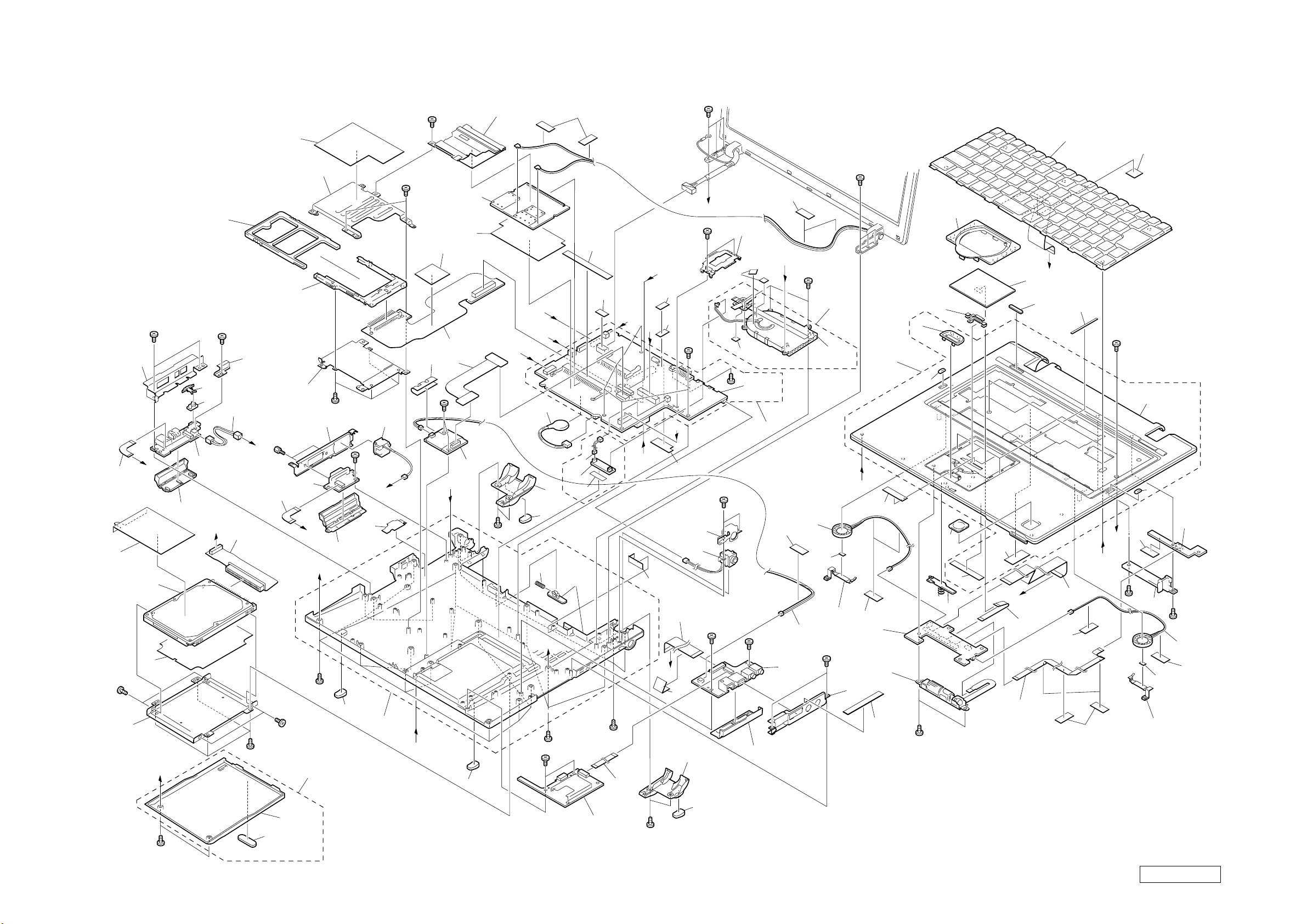
3-1. Main Section
Ref.No. Part No. Description Ref.No. Part No. Description
1 1-477-283-21 $# KEYBOARD UNIT (US)
2 4-662-400-02 COVER (TP)
3 1-796-319-11 PAD, TOUCH
4 4-666-738-21 (VX89P)...LABEL (ID)
4 4-666-738-31 (VX89)...LABEL (ID)
63 4-662-573-02 SPACER (WL)
64 4-662-574-02 SWITCH (WL)
* 65 4-662-570-02 BRACKET (IO L)
66 1-761-380-23 # CARD, MODEM
67 1-685-170-11 FPC (MDC)
4 4-666-738-41 (VX89K)...LABEL (ID)
5 4-663-835-01 TAPE (TP)
6 4-657-945-01 PLATE (TP)
7 4-662-405-02 ESCUTCHEON (JOG)
8 X-4624-713-6 HOUSING (PARM REST) ASSY
9 4-662-787-01 CUSHION (CENTER BZ)
10 A-8067-219-A COMPLETE PWB SWX-103
11 4-662-421-02 CASE (CAPS)
12 1-825-150-21 SPEAKER, (2.0CM)
13 4-658-789-02 TAPE (HARNESS)
14 4-663-133-01 HOLDER (SP) (R)
15 1-824-088-11 CABLE,FLEXIBLE FLAT (SWX1-SWX2
16 1-824-085-11 CABLE, FLEXIBLE FLAT(MBX-SWX1)
17 1-824-089-11 CABLE, FLEXIBLE FLAT (SWX1-TP)
18 X-4624-886-2 PARM ASSY, LATCH
21 4-662-407-01 WINDOW (MS)
22 1-476-945-11 ENCODER, JOG
23 A-8067-218-A $ COMPLETE PWB SWX-101
24 4-663-132-01 HOLDER (SP) (L)
25 1-825-150-11 SPEAKER, (2.0CM)
* 26 4-662-918-01 PROTECTER HEATSINK
* 28 1-763-838-11 DC FAN (WITH HEATSINK)
29 A-8112-160-A $# C/P (MBX-56) (P900) (S)
30 1-468-624-21 BATTERY, VANADIUM-LITHIUM
* 31 4-662-925-01 DC, HOLDER
32 1-961-483-21 HARNESS (WITH DC JACK)
33 1-960-827-71 HARNESS (2 PIN)
34 A-8067-207-A $ COMPLETE PWB CNX-174
* 35 4-662-571-01 BRACKET (IO R)
36 X-4624-779-2 ASSY DOOR R
* 68 4-662-665-02 PLATE (PCC)
69 1-684-994-11 FPC (PC CARD, WITH CONNECTOR)
70 1-816-580-11 CONNECTOR, PC CARD (EJECTOR)
71 4-643-832-41 DUMMY CARD
* 72 4-662-664-02 PROTECTOR (PCC)
73 4-663-422-01 SHEET (FPC MDC)
74 4-663-421-02 SHEET (MPCI)
75 1-761-495-11 CARD, WIRELESS LAN
77 4-664-890-02 CUSHION HEATSINK
78 4-664-957-01 SHEET KEYBOARD
81 4-665-008-01 SHEET (SP)
82 4-665-009-01 TAPE (MPCI)
83 4-664-909-01 SHEET (BRACKET R)
84 4-663-932-01 SHEET (DC), INSULATING
85 4-664-221-01 SHEET (MBX), INSULATING
86 4-664-224-01 SHEET (FFC 30)
87 4-660-499-11 CUSHION DOOR
88 4-657-991-01 SHEET (JOG), INSULATING
89 4-664-253-02 PLATE (WL)
90 4-664-254-02 SHEET (HDD), CONDUCTIVE
91 4-664-581-01 SHEET (PC CARD)
92 X-4624-953-2 PLATE (MINI-PCI) ASSY
97 4-665-091-01 PLATE (KEYBOARD)
98 4-665-092-01 CUSHION (PKB)
99 4-665-317-01 CUSHION MZ
100 4-665-096-01 TAPE (COVER TP)
101 4-664-828-01 ADHESIVE TAPE (BOTTOM)
104 A-8067-505-A $ COMPLETE PWB FLT-7
105 1-961-895-11 HARNESS
106 4-666-382-01 ADHESIVE (TAPE) (FLT-7)
37 1-824-086-11 CABLE, FLEXIBLE FLAT (MBX-CNX)
38 4-663-369-02 COVER (R), FOOT
39 4-662-877-02 RUBBER (REAR), FOOT
40 1-824-087-11 CABLE, FLEXIBLE FLAT (CNX-IFX)
41 A-8067-544-A $ COMPLETE PWB IFX-207
42 4-662-878-02 RUBBER (FRONT), FOOT
43 X-4624-811-2 HOUSING (BOTTOM) ASSY
44 4-659-832-01 SHEET,THERMAL
46 4-635-956-01 SPRING (B), COMPRESSION COIL
47 4-663-370-02 COVER (L), FOOT
48 4-663-438-02 SHEET
49 X-4624-888-2 DOOR (HDD) ASSY
* 50 4-662-388-02 BRACKET (HDD)
51 4-664-157-01 SHEET (HDD)
52 A-8059-344-A $# ASSY HDD 30GB (T,20,F)(S)
53 1-685-027-11 PWB, FLEXIBLE PRINT (HDD)
54 1-684-993-11 FPC (VGA)
55 X-4624-780-4 ASSY DOOR V
56 A-8067-204-A $ COMPLETE PWB CNX-176
57 1-961-763-11 HARNESS, RJ-45
* 58 4-662-572-01 BRACKET (IO V)
59 1-791-608-21 CONNECTOR, HARNESS WITH (DC)
60 A-8067-205-A $ COMPLETE PWB CNX-173
61 X-4624-781-4 ASSY DOOR L
62 1-684-986-11 FPC (I. LINK)
B1 4-664-453-01 SCREW (M2X4), SPECIAL HEAD
B2 4-664-453-11 SCREW (M2X5.5), SPECIAL HEAD
B3 4-641-726-21 SCREW (M2), SPECIAL HEAD
B4 4-635-966-01 SCREW (HEX)
B5 4-635-301-01 SCREW M3X4
3-2
Confidential
PCG-VX89/VX89K/VX89P (AM)
Page 8
B1
92
13
B1
90
62
B5
50
65
51
K
52
B1
A
61
60
64
63
B
71
B1
59
53
89
B3
J
B4
54
B5
91
70
68
56
I
49
D
B1
72
B1
55
42
B3
48
H
43
1
28
24
35
B1
D
13
23
83
22
2
E
3
6
7
8
9
5
21
97
101
18
B1
4
M
17
15
100
C
16
13
13
B3
B3
29
13
L
13
34
B1
Supplied
with 28
25
81
33
B3
75
F
26
B3
38
32
31
B3
B1
B1
B3
77
44
Supplied
with 29
36
74
73
I
69
88
67
B3
5758
66
F
B3
A
42
J
K
30
47
39
46
C
B1
B3
82
105
104
106
Supplied
with 43
99
B1
40
H
B
E
M
99
98
G
85
84
37
G
86
B2
Supplied with 8
13
L
B1
78
9
11
10
B1
12
13
81
14
B1
87
Supplied
with 49
41
39
B3
Confidential
PCG-VX89/VX89K/VX89P (AM)3-3 3-4
Page 9
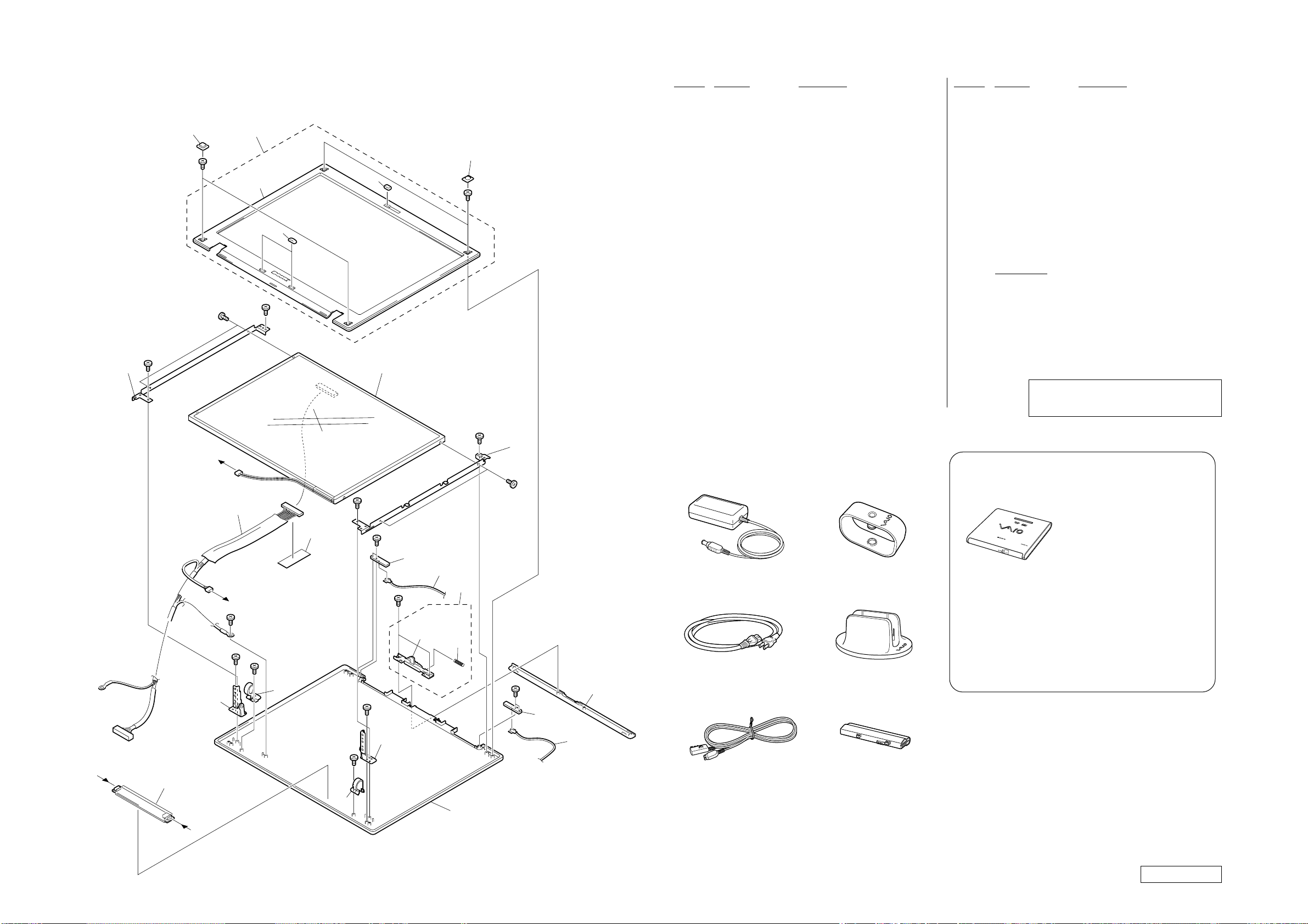
3-2. LCD Section – Made by HI –
805
Clamp (1)
801
AC Adaptor (1)
802
Power Cord (1)
804
i LINK Connection Cord (1)
807
Battery Pack (1)
806
Stand (1)
808
CD-RW/DVD-ROM Drive
(PCGA-CRWD2)
• The CD-RW/DVD-ROM Drive itself does not have the Part No.
Refer to the PCGA-CRWD2 Service manual (9-874-566-01).
Because only the 804 iLINK Connection Cord is reguired for
connection with a computor, the follwing parts are not supplied
with the CD-RW/DVD-ROM drive.
1-476-940-22 ADAPTOR, AC
1-757-562-31 CORD, POWER
1-790-763-21 CORD, CONNECTION
4-663-161-11 MANUAL, INSTRUCTION
4-663-751-11 MANUAL, INSTRUCTION (FIRST)
206
B2
202
Supplied
with 202
204
203
201
B2
Ref.No. Part No. Description
Ref.No. Part No. Description
201 4-662-789-01 COVER (LCD), SCREW
202 X-4624-714-2 HOUSING (BEZEL) ASSY
203 4-662-788-01 CUSHION, LATCH
204 4-662-787-01 CUSHION (CENTER BZ)
206 4-659-342-01 BLIND (LCD), SCREW
0 801 1-476-943-21 $ ADAPTOR, AC
0802 1-757-562-31 CORD, POWER
* 207 4-662-427-01 BRACKET (LCD L)
208 A-8067-411-A $# LCD(14HI)ASSY (S)
* 209 4-662-434-01 BRACKET (LCD R)
210 1-961-709-11 HARNESS, LCD
211 4-658-789-02 TAPE (HARNESS)
212 A-8067-221-A COMPLETE PWB IFX-209
213 1-823-844-21 CABLE,COAXIAL (BLACK) (L670)
214 X-4624-887-1 DISPLAY ASSY, LATCH
215 4-639-623-01 SPRING (LATCH), COIL
217 A-8067-220-A COMPLETE PWB IFX-208
ACCESSORIES
************
804 1-823-439-11 CORD, ILINK CONNECTION
805 4-657-363-01 CLAMP
806 X-4625-087-1 STAND ASSY
807 A-8110-748-A BP2S/HI (U) ASSY (S)
4-668-323-01 (VX89K)...
SPECIFICATION SHEET, 2370UAZ
4-667-818-01 QUICK START, 2370UA
LOOK AT EXPLODED VIEWS OF THE PART
**********************************
B1
210
B
B6
B6
211
B1
B3
223
B1
B3
B6
207 208
A
222
B3
B3
212
Supplied
with 214
218
214
215
B6
B3
B3
209
217
227
218 1-823-844-31 CABLE,COAXIAL (GRAY) (L930)
808 PCGA-CRWD2
219 X-4624-812-2 HOUSING (DISPLAY) ASSY
220 X-4624-716-2 HINGE (RIGHT) ASSY
221 4-662-383-02 COVER (HINGE) (R)
222 X-4624-717-2 HINGE (LEFT) ASSY
223 4-662-382-02 COVER (HINGE) (L)
224 1-476-735-11 INVERTER UNIT
227 X-4625-019-1 ESCUTCHEON (WL) ASSY
B1 4-664-453-01 SCREW (M2X4), SPECIAL HEAD
B2 4-664-453-11 SCREW (M2X4), SPECIAL HEAD
B3 4-641-726-21 SCREW (M2), SPECIAL HEAD
B6 4-641-726-71 SCREW (M2), SPECIAL HEAD
The components identified by mark 0 or dotted
line with mark 0 are critical for safety.
Replace only with part number specified.
B
224
A
B3
221
220
219
3-5 3-6
213
Confidential
PCG-VX89/VX89K/VX89P (AM)
(END)
Page 10
PCG-VX89/VX89K/VX89P (AM)
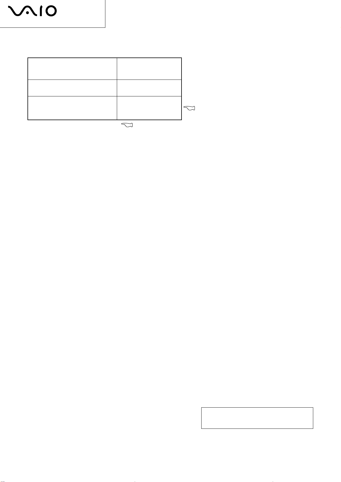
List of PCG-VX Series (As of October, 2002)
Model Name
PCG-VX88
PCG-VX88P
PCG-VX89
PCG-VX89K
PCG-VX89P
Service Manual
Part No.
9-874-532-01
9-876-021-01
: Additional Models
9-876-021-01
Sony Corporation
— 20 —
This manual and the constituent data may not be
replicated, copied nor reprinted in whole or in part
without prior written authorization of Sony Corporation.
English
2002J1600-1
© 2002 Sony Corporation
Published by Sony EMCS VAIO-GSC [SNT]
Page 11
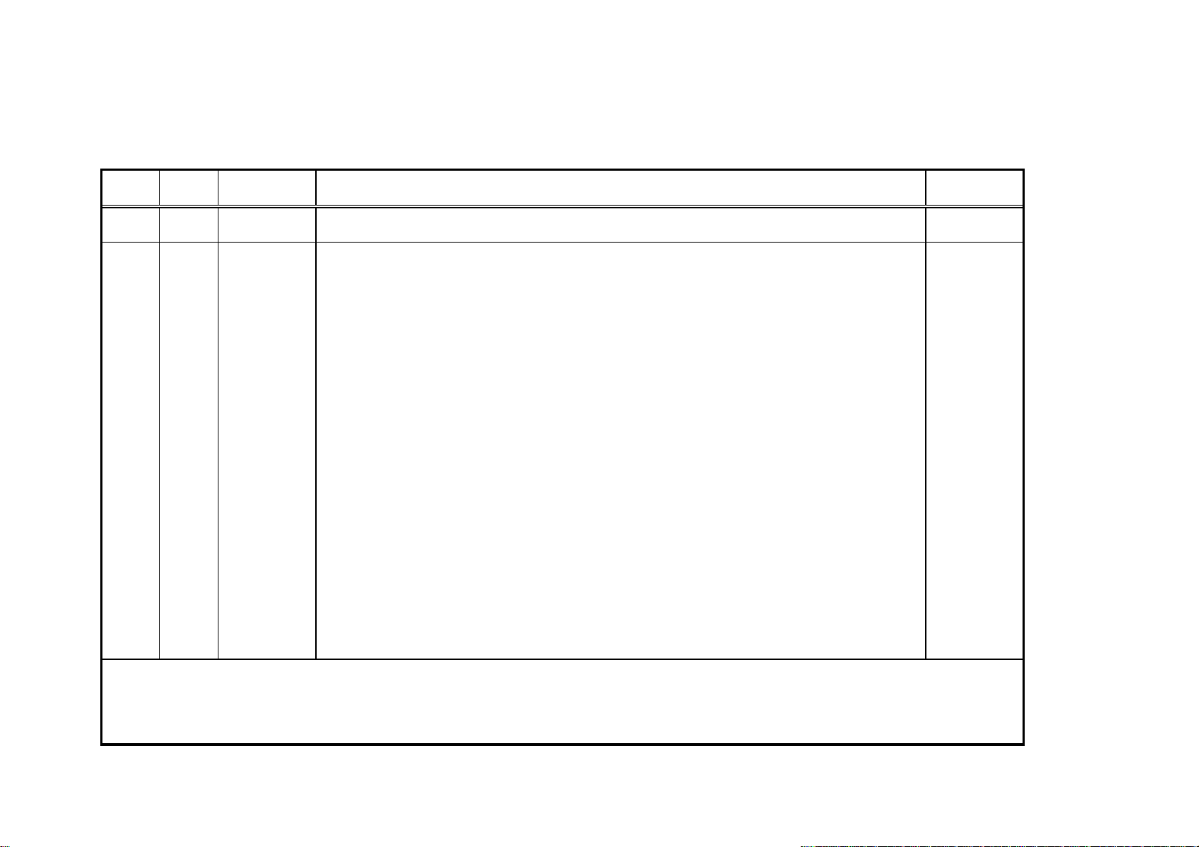
Revision History
Suffix Ver. Date Contents QM No.
-01 Ver. 1 2002.10.04
First
Edition
< Remarks >
[Confidential]
PCG-VX89/VX89K/VX89P (AM)
 Loading...