

PCG-FX777/FX877
SERVICE MANUAL
Ver 1-2001J
All the supplementary
information are attached
at the end of data files.
Update List
Lineup : PCG-FX777
PCG-FX877
Illust : PCG-FX877
For American Area
Latin Model
S400
Confidential
9-872-288-01
NOTEBOOK COMPUTER
Information in this document is subject to change without notice.
Sony and VAIO are trademarks of Sony . Intel logo and Intel Inside
logo are registered trademarks of Intel Corporation. Pentium MMX
is a trademark of Intel Corporation. Microsoft, MS-DOS, W indows,
the W indows 95 and W indows 98 log o are trademarks of Microsoft
Corporation.
All other trademarks are trademarks or registered trademarks of
their respective owners. Other tr ademarks and trade names may be
used in this document to refer to the entitles claiming the marks and
names or their produces. Sony Corporation disclaims any proprietary
interest in trademarks and trade names other than its own.
Caution Markings for Lithium/Ion Battery - The following or similar
texts shall be provided on battery pack of equipment or in both the
operating and the service instructions.
CAUTION: Danger of explosion if battery is incorrectly replaced.
Replace only with the same or equivalent type recommended by
the manufacturer. Discard used batteries according to the
manufacturer’s instructions.
CAUTION: The battery pack used in this de vice may present a f ire
or chemical burn hazard if mistreated. Do not disassemble, heat
above 100°C (212°F) or incinerate.
Dispose of used battery promptly.
Keep away from children.
CAUTION: Changing the back up battery.
• Overcharging, short circuiting, reverse charging, multilation or
incineration of the cells must be avoided to prev ent one or more of
the following occurrences; release of toxic materials, release of
hydrogen and/or oxygen gas, rise in surface temperature.
• If a cell has leaked or vented, it should be replaced immediately
while avoiding to touch it without any protection.
Service and Inspection Precautions
1. Obey precautionary markings and instructions
Labels and stamps on the cabinet, chassis, and components identify areas
requiring special precautions. Be sure to observe these precautions, as well
as all precautions listed in the operating manual and other associated
documents.
2. Use designated parts only
The set’s components possess important safety characteristics, such as
noncombustibility and the ability to tolerate large voltages. Be sure that
replacement parts possess the same safety characteristics as the originals.
Also remember that the 0 mark, which appears in circuit diagrams and
parts lists, denotes components that have particularly important safety
functions; be extra sure to use only the designated components.
3. Always follow the original design when mounting
parts and routing wires
The original layout includes various safety features, such as inclusion of
insulating materials (tubes and tape) and the mounting of parts above the
printer board. In addition, internal wiring has been routed and clamped so
as to keep it away from hot or high-voltage parts. When mounting parts or
routing wires, therefore, be sure to duplicate the original layout.
4. Inspect after completing service
After servicing, inspect to make sure that all screws, components, and wiring
have been returned to their original condition. Also check the area around
the repair location to ensure that repair work has caused no damage, and
confirm safety.
5. When replacing chip components...
Never reuse components. Also remember that the negati ve side of tantalum
capacitors is easily damaged by heat.
6. When handling flexible print boards...
•The temperature of the soldering-iron tip should be about 270C.
•Do not apply the tip more than three times to the same pattern.
•Handle patterns with care; never apply force.
Caution: Remember that hard disk drives are easily damaged by
vibration. Always handle with care.
ATTENTION AU COMPOSANT AYANT RAPPORT
À LA SÉCURITÉ!
LES COMPOSANTS IDENTIFÉS P AR UNE MARQUE 0 SUR LES
DIAGRAMMES SCHÉMA TIQUES ET LA LISTE DES PIÈCES SONT
CRITIQUES POUR LA SÉCURITÉ DE FONCTIONNEMENT. NE
REMPLACER CES COMPOSANTS QUE PAR DES PIÈSES SONY
DONT LES NUMÉROS SONT DONNÉS DANS CE MANUEL OU
DANS LES SUPPÉMENTS PUBLIÉS PAR SONY.
Confidential
PCG-FX777/FX877 (AM)
— 2 —

TABLE OF CONTENTS
Section Title Page
CHAPTER 1. REMOVAL
1-1. Flowchart ......................................................................... 1-1
1-2. Main Electrical Parts Location Diagram ......................... 1-1
1-3. Removal ........................................................................... 1-2
1. Assy Hood Keyboard, Keyboard Unit ............................. 1-2
2. DC-Fan, Combination Drive............................................1-2
3. Combination Drive........................................................... 1-3
4. HDD, Door Battery.......................................................... 1-4
5. Assy Palmrest, Pad Touch, CNX-125 Board,
Plate Palmrest, Bracket Pad ............................................. 1-4
6. Display Assy, Cover Hinge .............................................. 1-5
7. PWS-13 Board, Latch Detector ...................................... 1-6
8. PC Card Connector, Card Modem,
MBX-49 Board, Bracket I/O, Lithium Battery................ 1-6
9. Speaker Unit, SWX-73 Board ......................................... 1-7
10. SO-DIMM........................................................................ 1-7
11. Card Modem (Removing from the bottom) ..................... 1-8
12. LCD Section
(FX877 Model) – Made by TS – .................................... 1-9
1. Assy Housing Bezel, LCD Unit ................................... 1-9
2. Inverter Unit, FPC, Assy Housing Display,
Harness LCD.............................................................. 1-10
13. LCD Section
(FX777 Model) – Made by HI – ................................... 1-11
1. Assy Housing Bezel (14 inch) ................................... 1-11
2. Bracket LCD Left, Bracket LCD Right,
LCD Unit (14 inch) .................................................... 1-12
3. FPC, Inverter Unit, Assy Housing Display,
Harness LCD.............................................................. 1-12
1-4. Replacing the CPU ........................................................ 1-13
1. Socket type 1,2............................................................... 1-13
1. Removing the CPU .................................................... 1-13
2. Installing the CPU ...................................................... 1-13
2. Socket type 3.................................................................. 1-14
1. Removing the CPU .................................................... 1-14
2. Installing the CPU ...................................................... 1-14
1-5. DIP Switch Setting of the MBX-49 Board .................... 1-15
(to 1-15)
Section Title Page
CHAPTER 2. SELF DIAGNOSTICS......................... 2-1
(to 2-1)
CHAPTER 3. BLOCK DIAGRAM............................... 3-1
(to 3-2)
CHAPTER 4. FRAME HARNESS DIAGRAM........ 4-1
(to 4-2)
CHAPTER 5. EXPLODED VIEWS AND
PARTS LIST............................................5-1
5-1. Main Section .................................................................... 5-2
5-2. FDD Section .................................................................... 5-5
5-3. LCD Section (FX877 Model) – Made by TS – ............... 5-7
5-4. LCD Section (FX777 Model) – Made by HI –................ 5-9
5-5. Connector Section (CH Type Only)............................... 5-11
(to 5-12)
— 3 —
Confidential
PCG-FX777/FX877 (AM)

MEMO
CHAPTER 1.
REMOVAL
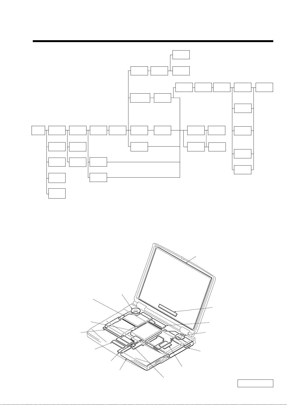
1-1. Flowchart
POWER
OFF
ASSY
HOOD
KEYBOARD
SO-DIMM
BATTERY
PACK
FDD
CARD
MODEM
P 1-8
KEYBOARD
UNIT
P 1-2P 1-2
SPEAKER
UNIT
P 1-7P 1-7
SWX-73
BOARD
P 1-7
DOOR
BATTERY
P 1-3
HDD
P 1-3
DC-FAN
P 1-2
ASSY
P ALMREST
P 1-4
PLA TE
P ALMREST
P 1-4
COMBINA TION
DRIVE
P 1-2
P 1-3
LATCH
DETECTOR
P 1-6
PC CARD
CONNECTOR
P 1-6
BRACKET
PAD
P 1-4
DISPLAY
ASSY
P 1-5
PWS-13
BOARD
P 1-6
CNX-125
BOARD
P 1-4
PAD
TOUCH
P 1-4
COVER
HINGE
P 1-5
∗ : FX877 Model
( ) : FX777 Model
HOUSING
BEZEL
∗P 1-9
(P 1-11)
BRACKET
I/O
P 1-6
CARD
MODEM
P 1-6
ASSY
LCD
UNIT
∗P 1-9
(P 1-11)
MBX-49
BOARD
P 1-6
LITHIUM
BATTERY
P 1-6
INVERTER
UNIT
∗P 1-10
(P 1-12)
HARNESS
LCD
∗P 1-10
(P 1-12)
FPC
∗P 1-10
(P 1-12)
BRACKET
LCD LEFT
(P 1-12)
BRACKET
LCD RIGHT
(P 1-12)
ASSY
HOUSING
DISPLAY
∗P 1-10
(P 1-12)
• P XX means pages that appears in this manual.
• Remember that hard disk drives are easily damaged by vibration. Always handle with care.
1-2. Main Electrical Parts Location Diagram
LCD Unit
Speaker Unit
DC Fan
HDD
MBX-49 Board
CNX-125 Board
PWS-13 Board
FD Drive
Card Modem
Pad Touch
1-1
Speaker Unit
Combination Drive
(CD-RW/DVD-ROM)
Inverter Unit
SWX-73 Board
Confidential
PCG-FX777/FX877 (AM)
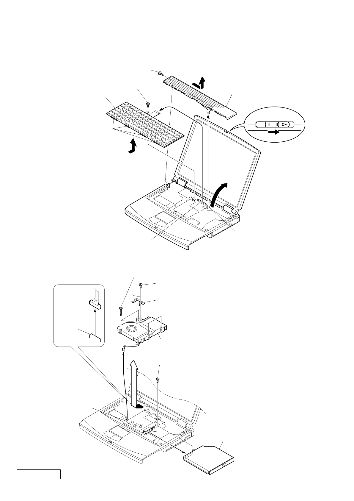
1-3.Removal
1. Assy Hood Keyboard, Keyboard Unit
3Screw M2X4 Special Head (Black)
8Screw M2X4 Special Head (Black)
q;Keyboard Unit
Four Claws
9
MBX-49 Board
CN1902
4Pull it up sliding it to the right.
6Assy Hood Keyboard
7
5
1
2
MBX-49 Board
CN2004
2. DC-Fan, Combination Drive
1
MBX-49
Board
CN701
MBX-49 Board
CN102
5Screw (M2) 0 Number P3 Kind (X4) (Black)
2+B M2 (X2) (Gold)
3Plate ground
7DC Fan
4
9Screw M2X6 Special Head (Gold)
6
8
qaCombination Drive
Confidential
PCG-FX777/FX877 (AM)
q;
1-2
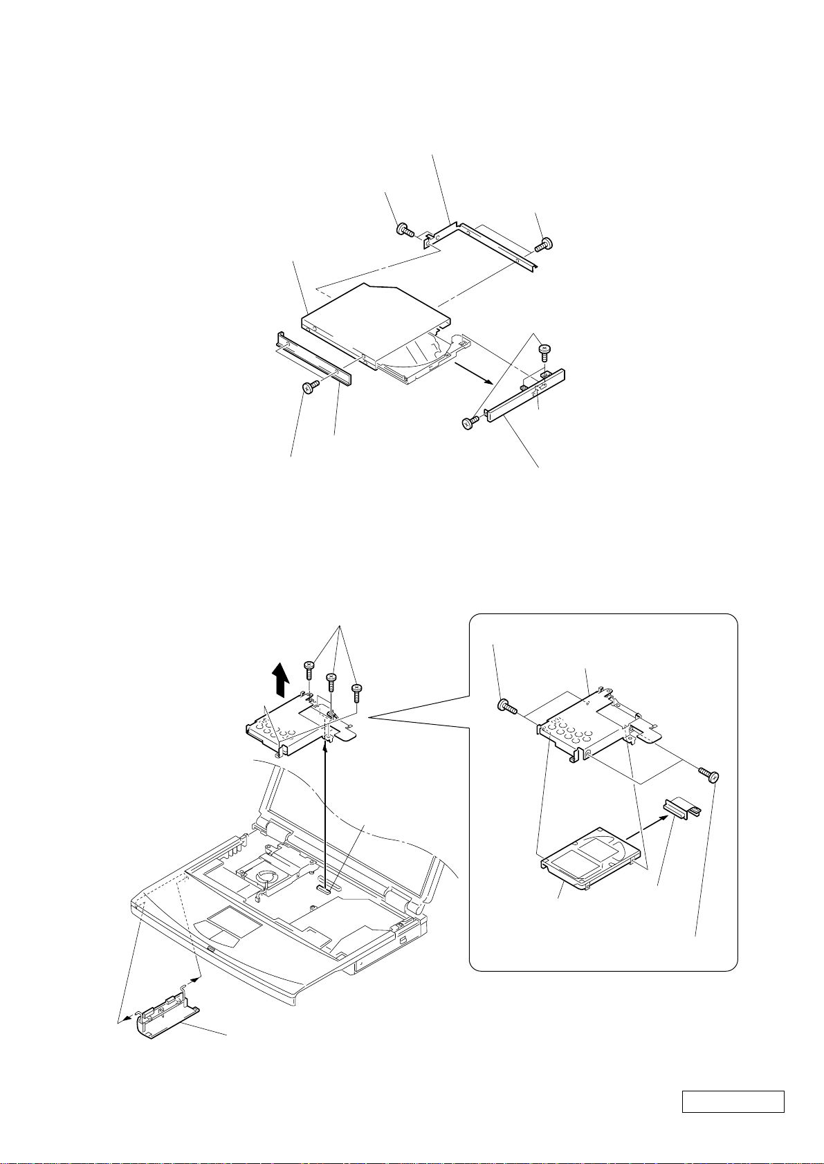
3. Combination Drive
5Bracket CD-ROM R
3+B M2 (NOJI) (X2) (Gold)
8COMBO Drive
1+B M2 (NOJI) (X2) (Gold)
4. HDD, Door Battery
4+B M2 (NOJI) (X2)
(Gold)
6Screw (M1.7X3.5) (X3) (Black)
Claw
2Bracket (CD-ROM L)
7Assy Door DVD-RW (PA)
1Screw M2X6 Special Head (X6) (Gold)
3
2FPC 50Pin
(for HDD)
MBX-49 Board
CN2201
1Screw M3X4 (X2) (Gold)
3Bracket HDD
5HDD
4FPC 50Pin
(for HDD)
2Screw M3X4 (X2) (Gold)
4Door Battery
1-3
Confidential
PCG-FX777/FX877 (AM)
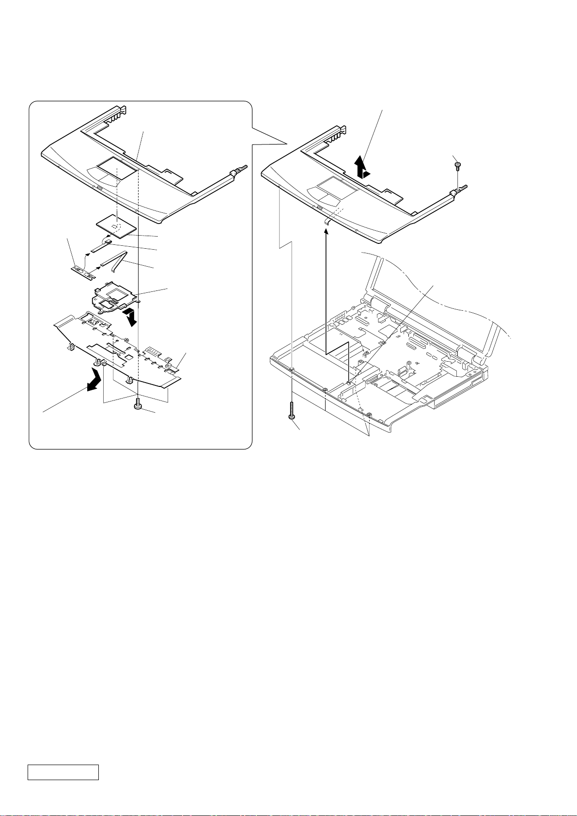
5. Assy Palmrest, Pad Touch, CNX-125 Board, Plate Palmrest, Bracket Pad
3Pull it to the front slightly
and raise to remove it.
1Screw M2X4
Special Head
(Black)
7CNX-125
Board
Assy Palmrest
9Pad, Touch
8FPC (TP-CNX)
6FPC (SWX-PWS)
5Bracket Pad
4Remove by pressing
to rear.
3Plate
Palmrest
4
PWS-13 Board
CN4004
2
Move down the front
1M2X4 Special
portion slightly
downward and then pull it out.
Head (x4) (Black)
2Screw (M2),
0 Number P3 Kind (X4) (Black)
Confidential
PCG-FX777/FX877 (AM)
1-4
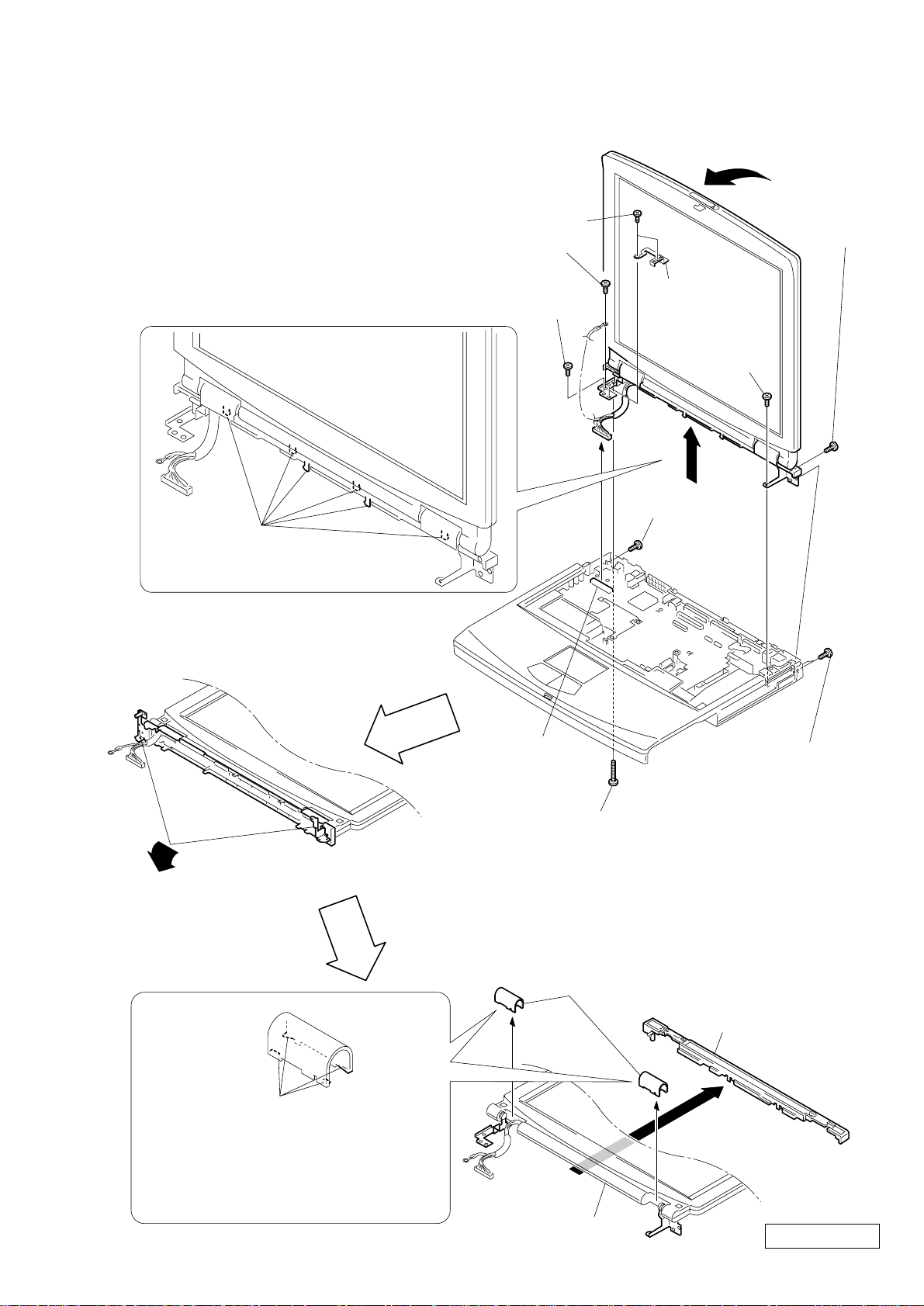
6. Display Assy, Cover Hinge
3+B M2 (X2) (Gold)
9Screw M2X6 Special
Head (Gold)
q;Screw +B 2X12 (Silver)
1Stand the LCD upright
to the MBX-49 board.
7Screw M2.6
Cross (Hole)
Bind (Black)
4Plate ground
qaM2X6 Special
Head (Gold)
2
qs
5Screw M2.6
Six Claws
MBX-49 Board
CN701
8Screw (M2), 0 Number P3 Kind (Black)
qdClose simultaneously both left and right hinges approximately 90°
in the direction of the arrow.
Cross (Hole)
Bind (Black)
6Screw M2.6 Cross
(Hole) Bind (X2) (Black)
Four Claws
Note : To remove the cover hinge, bend
slightly the center of the display
base facilitates the removal work.
Display Assy
1-5
qfCover Hinge
qhDisplay Base
qg
Confidential
PCG-FX777/FX877 (AM)
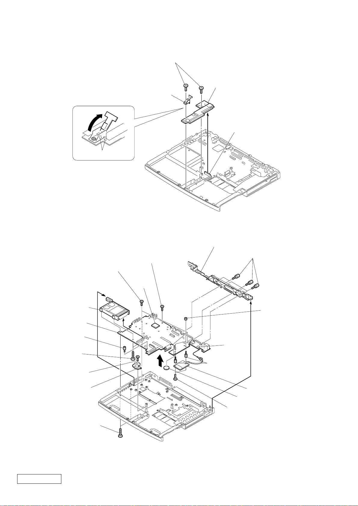
7. PWS-13 Board, Latch Detector
2Screw M2X4 Special Head (X2) (Black)
5Latch Detector
6PWS-13 Board
1
3
MBX-49 Board CON22
4Two Claws
8. PC Card Connector, Card Modem, MBX-49 Board, Bracket I/O, Lithium Battery
qjBracket I/O
qhScrew (HEX) (X6) (Silevr)
1Screw M2X4 Special
Head (X3) (Black)
2+B 2X4 (Silver)
1
*
CPU
9PC Card Connector
qjMBX-49 Board
3Screw (MBX)
(Silver)
8Screw +B 2X14
(X2) (Silver)
4Screw M2X4 Special
Head (X2) (Black)
5Bracket Bay Connector
6Screw (M2) 0 Number
P3 Kind (X2) (Black)
Confidential
PCG-FX777/FX877 (AM)
qsNUT M2
TYPE2 (X2)
CON4
qa
7
qgSpacer
(MBX) (X2)
2
qfCard Modem
*
0Lithium Battery
qdGrip M2 (X2) (Black)
∗1 When removing the CPU, refer to “ 1-4. Replacing the CPU ”.
∗2 Modem card can be removed from the bottom.
Refer to the subsequent paragraph “ 11. Card Modem ” for more details.
1-6
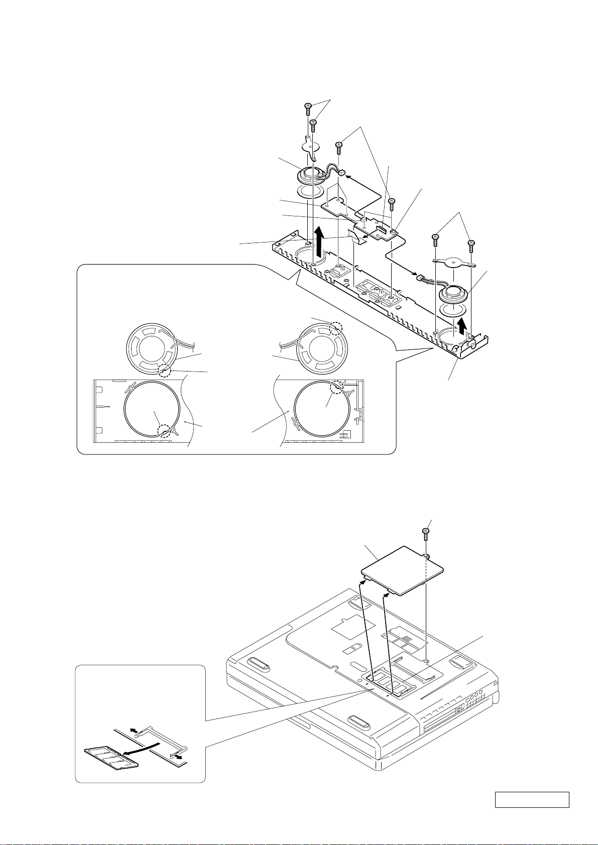
9. Speaker Unit, SWX-73 Board
Note : When removing the speaker
unit, be sure not to damage
the hood keyboard.
7Speaker Unit
5SWX-73 Board
SWX-73 Board
CN303
FFC (PPK)
Note : To re-install it, align the notch
of the speaker unit with the
projection of the hood keyboard.
Speaker Unit
Notch
6Screw M2X4 (X2) (Black)
4Screw M2X4 (X5) (Black)
SWX-73 Board
3
CN301
SWX-73 Board
CN302
8Screw M2X4 (X2) (Black)
1
2
9Speaker Unit
Projection
10. SO-DIMM
Notch
Hood Keyboard
Projection
Hood
Keyboard
1Screw M2X4
Special Head (Black)
2Door DIMM
SO-DIMM
Removal of SO-DIMM
a → b
a
b
a
1-7
Confidential
PCG-FX777/FX877 (AM)
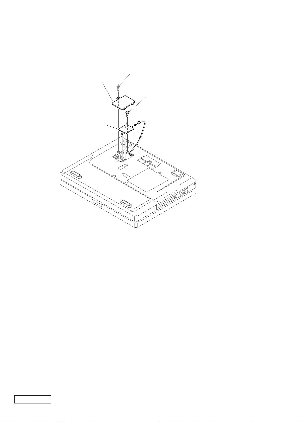
11. Card Modem (Removing from the bottom)
1Screw M2X4 Special Head (Black)
2Door Modem
3Grip M2 (X2) (Black)
4Card Modem
5
Confidential
PCG-FX777/FX877 (AM)
1-8
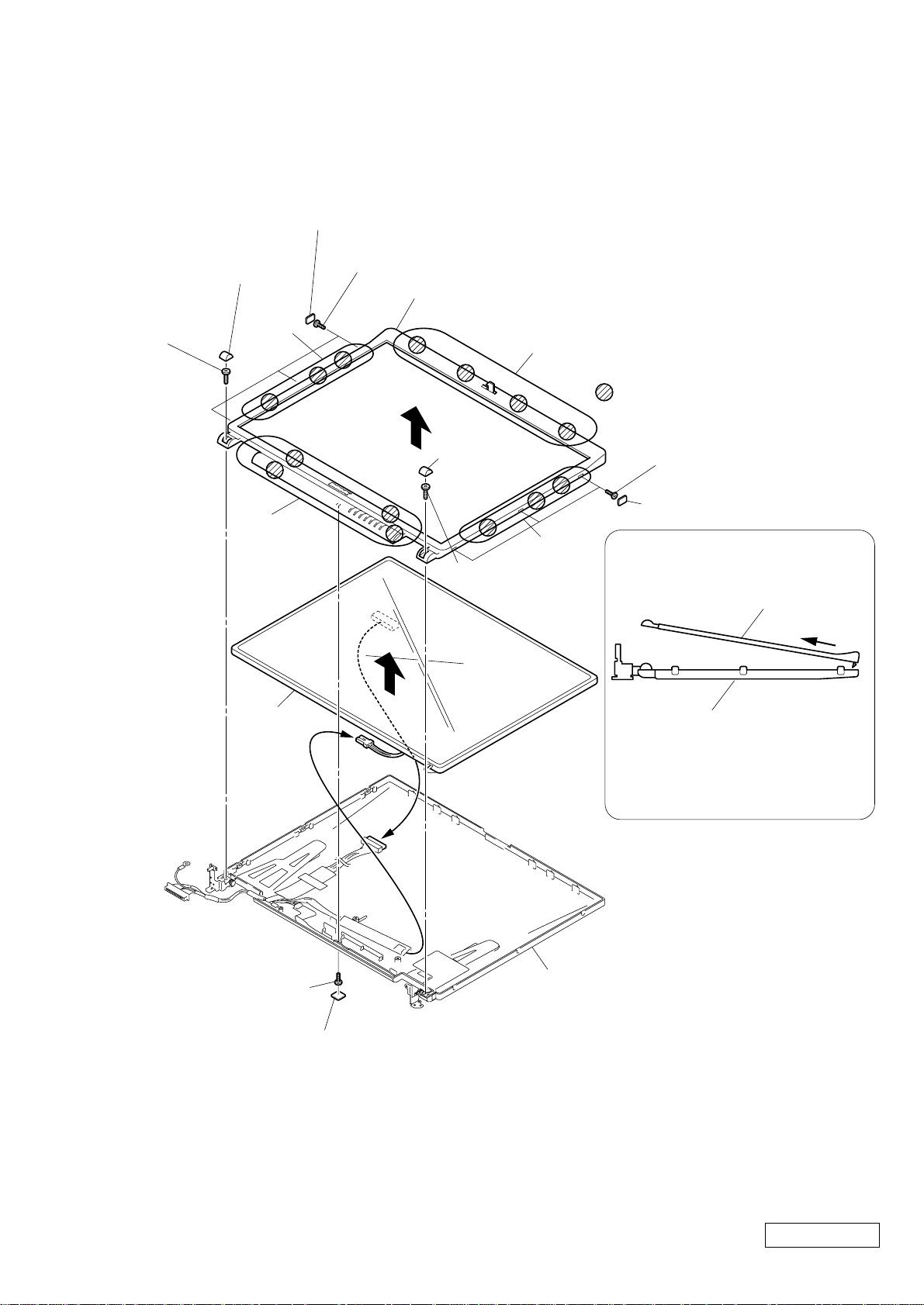
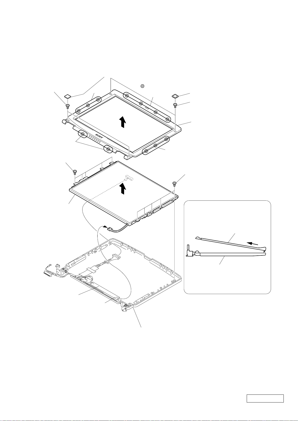
12. LCD Section (FX877 Model) – Made by TS –
How to release the claw A.
Pull the Assy Housing Bezel
15SA-Z as shown to release
the claw A.
Assy Housing Bezel 15SA-Z
Assy Housing Display 15SA-Z
A
Order of releasing the claws C → B → A
Order of locking the claws A → B → C
Assy Housing Display 15SA-Z
: claw part
1Cover Screw Side (15) (X3)
5Cover Screw Lower
3Cover Screw
Shaft
3Cover Screw
Shaft
4+P 2.6X6
Lock Precision
Type3 (Black)
4+P 2.6X6 Lock
Precision Type3
(Black)
6Screw M2X4 Special
Head (Black)
1Cover Screw Side (15) (X3)
2+P M2X3 Lock (X3) (Gold)
2+P M2X3 Lock (X3) (Gold)
A
B
7
0
8
9
B
C
Assy Housing Bezel 15SA-Z
LCD unit
1. Assy Housing Bezel, LCD Unit
1-9
Confidential
PCG-FX777/FX877 (AM)
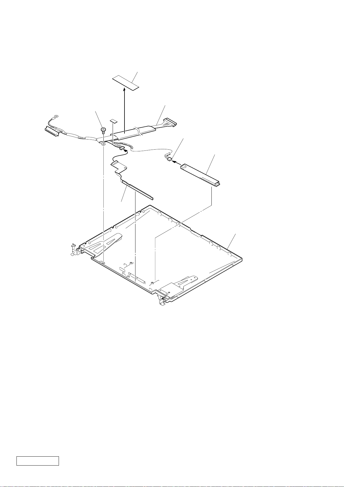
2. Inverter Unit, FPC, Assy Housing Display, Harness LCD
6Filament Tape
7Screw M2X4
Special Head (Black)
5
8Harness LCD
Inverter Unit
CN2
2Inverter Unit
3
1
4FPC
9Assy Housing Display
15SA-Z
Confidential
PCG-FX777/FX877 (AM)
1-10
13. LCD Section (FX777 Model) – Made by HI–
Order of releasing the claws c → b → a
Order of locking the claws a → b → c
How to release the claw a
5
a
Pull the Assy Housing Bezel
14H-Z as shown to release
the claw a.
: claw part
a
b
c
b
1Cover Screw Lower (X2)
1Cover Screw Upper (X2)
2Screw M2X4 Special
Head (X2) (Black)
2Screw M2X4 Special Head (X2)
(Black)
4Screw M2X4 Special Head (X5) (Black)
4Screw M2X4 Special
Head (X5) (Black)
6
7
3
Assy Housing Display 14SA-Z
Inverter Unit
Inverter Unit
CN2
Assy Housing Bezel 14H-Z
Assy Housing Display 14SA-Z
Assy Housing Bezel 14H-Z
LCD Unit
1. Assy Housing Bezel (14 inch)
1-11
Confidential
PCG-FX777/FX877 (AM)
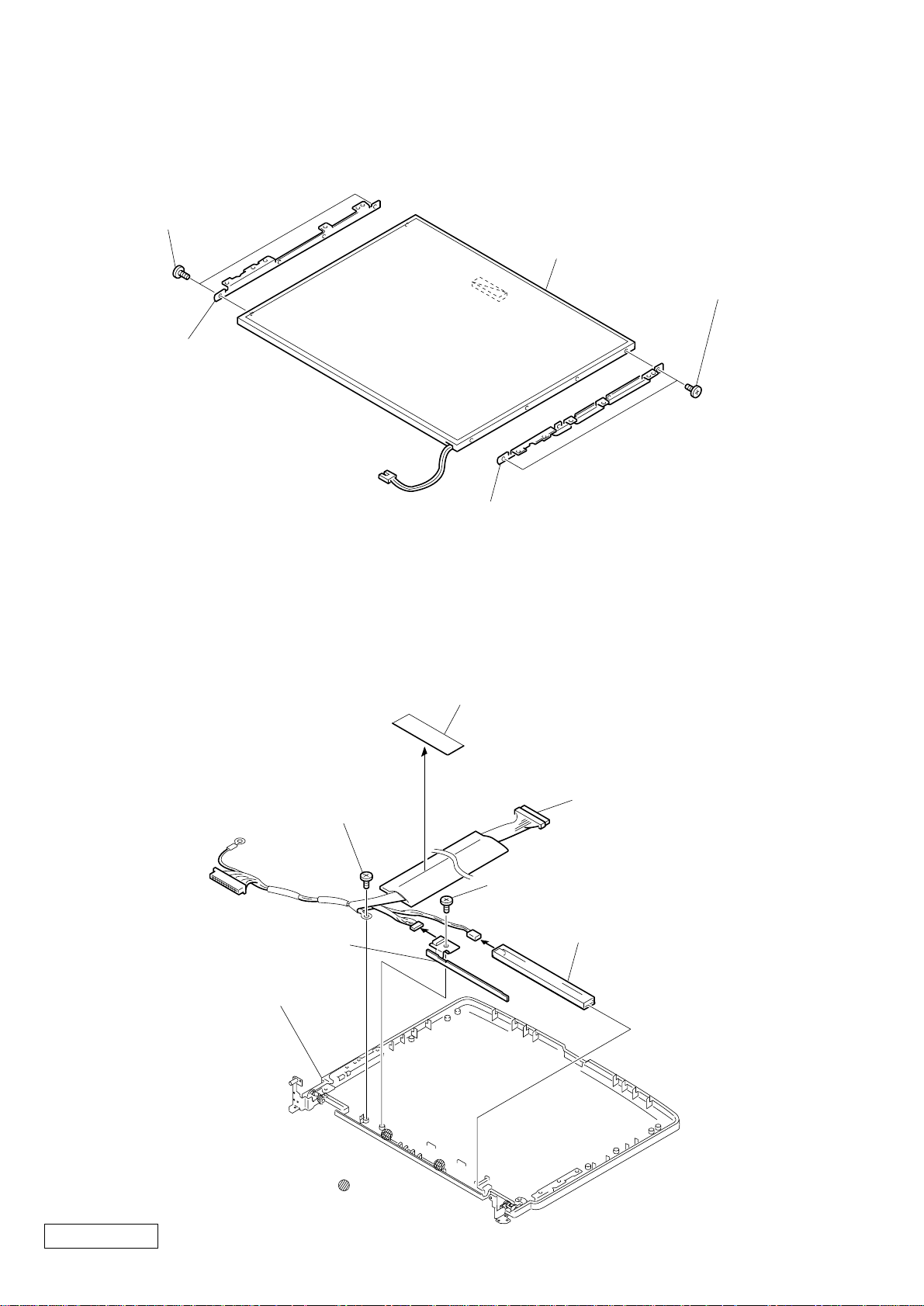
2. Bracket LCD Left, Bracket LCD Right, LCD Unit (14 inch)
3ACE (M2) +B Lock
(X2) (Silver)
5LCD Unit
4Bracket LCD
Left 14 (SA)
2Bracket LCD Right 14 (SA)
1ACE (M2) +B Lock
(X2) (Silver)
3. FPC, Inverter Unit, Assy Housing Display, Harness LCD
9Filament Tape
8
6Screw M2X4 Special Head
(Black)
5Screw M2X4 Special Head (Black)
1
4FPC
3
7Assy Housing Display
14SA-Z
0Harness LCD
2Inverter Unit
Confidential
PCG-FX777/FX877 (AM)
: claw part
1-12
1-4.Replacing the CPU
NOTE:
This computer uses either one of the two types of CPU socket.
The CPU locking position and the lock-release position are different depending on the types of the CPU socket.
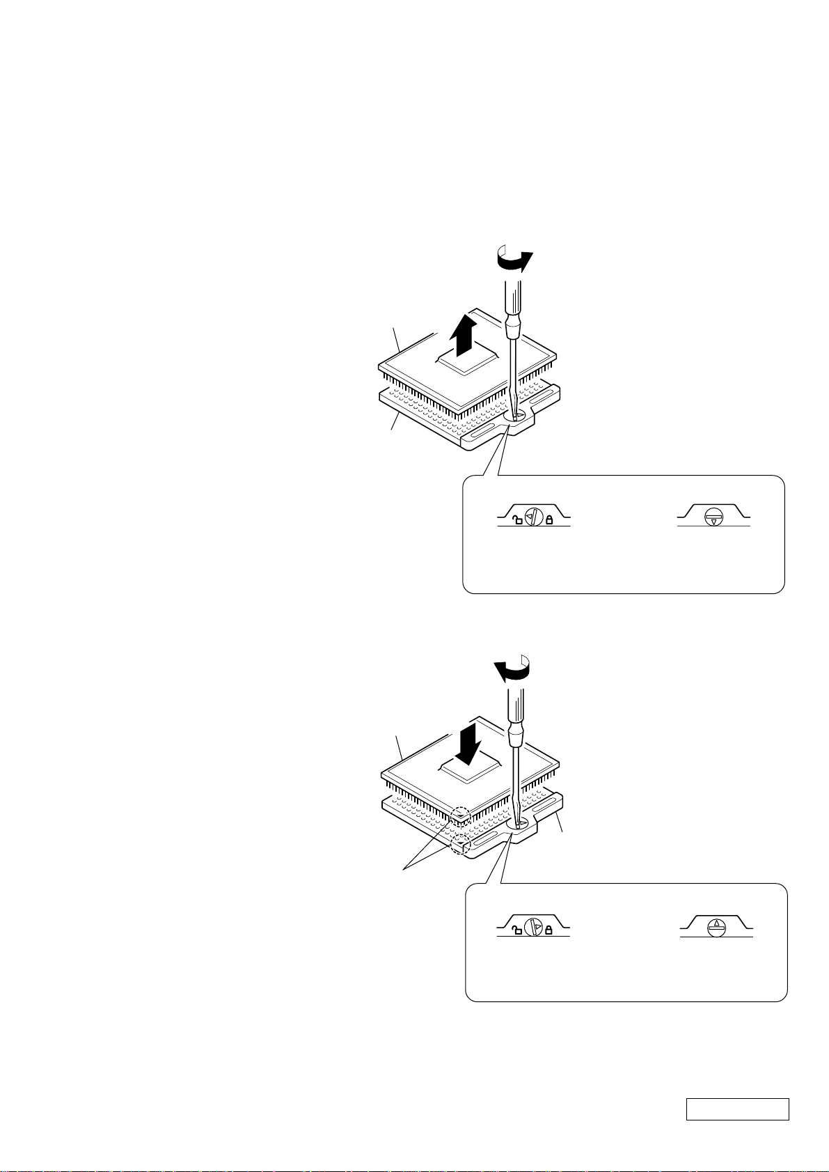
1. Socket type 1, 2
1. Removing the CPU
1
1 Insert a flat-blade screwdriver into the
notch as shown in the illustration and
rotate it so that the protrusion comes
to the lock release position.
2 Pull the CPU gently upward to lift it
out of the CPU socket.
CPU
CPU socket
2
2. Installing the CPU
1 Align the triangle reference mark of
the CPU with that of the CPU socket
and insert all the pins of the CPU to
the corresponding holes of the CPU
socket.
2 Insert a flat-blade screwdriv er into the
notch as shown in the illustration and
rotate it so that the protrusion comes
to the lock position.
Reference
marks
CPU
Lock release position
(made by HIROSE)
2
1
Lock release position
CPU socket
Lock position
(made by HIROSE)
NOTE:
Rotate a flat-blade screwdriv er to the lock position securely . If not, the operation of the CPU may become unstable.
Lock position
Confidential
1-13
PCG-FX777/FX877 (AM)
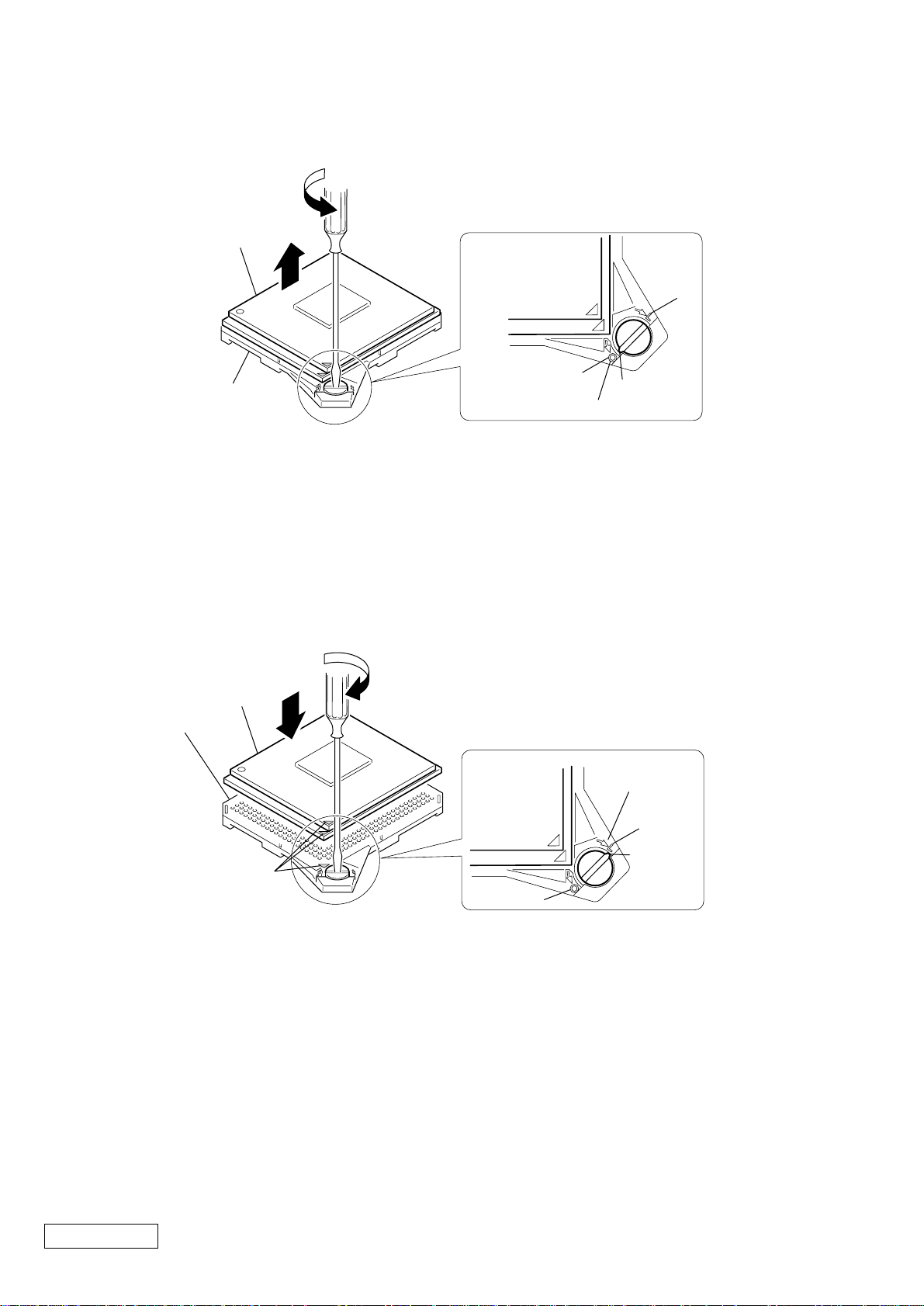
2. Socket type 3
1. Removing the CPU
1
CPU
CPU socket
1 Insert a flat-blade screwdriver into the notch as shown in the illustration and rotate it so that the
protrusion comes to the “O” (lock release) position.
2 Pull the CPU gently upward to lift it out of the CPU socket.
2. Installing the CPU
CPU
2
1
L
O
Protrusion
Lock release position [O]
2
CPU socket
Lock position [L]
L
Protrusion
Reference
marks
1 Align the triangle reference mark of the CPU with that of the CPU socket and insert all the pins of the CPU to
the corresponding holes of the CPU socket.
2 Insert a flat-blade screwdriver into the notch as shown in the illustration and rotate it so that the protrusion
comes to the “L” (lock) position.
NOTE:
• Considerable force is required to rotate a flat-blade screwdriver.
• Rotate a flat-blade screwdriver to the “L” (lock) position securely. If not, the operation of the CPU may
become unstable.
O
Confidential
PCG-FX777/FX877 (AM)
1-14
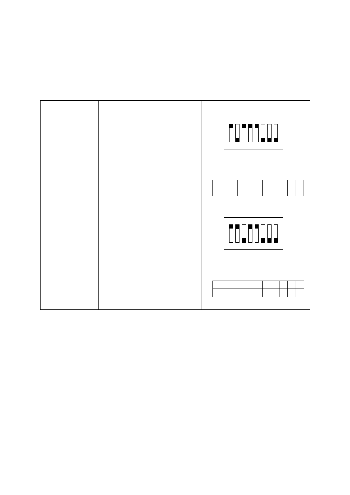
1-5. DIP Switch Setting of the MBX-49 Board
Set the DIP switch on the MBX-49 board (main board) to match with the LCD that is used in this computer, because
several types of LCD are used as shown in the following table and the DIP switch setting differs depending
on the LCD type.
MODEL
FX877
FX777
Name of LCD
TS
HI
Part No.
A-8058-271-A
A-8025-245-A
DIP switch setting
N
O
1234567
The upper position where ON indication is
shown is the ON position . The lower
position is the OFF position.
No.
ON/OFF
12345678
01000111
N
O
1234567
The upper position where ON indication is
shown is the ON position . The lower
position is the OFF position.
8
0 : ON 1: OFF
8
No.
ON/OFF
12345678
00100111
0 : ON 1: OFF
1-15
(END)
Confidential
PCG-FX777/FX877 (AM)

MEMO

CHAPTER 2.
SELF DIAGNOSTICS
ATTENTION
Please confirm “Self Diagnostics” method which will be informed you with distribution
of “Self Diagnostics” software.
2-1
(END)
Confidential
PCG-FX777/FX877 (AM)

MEMO
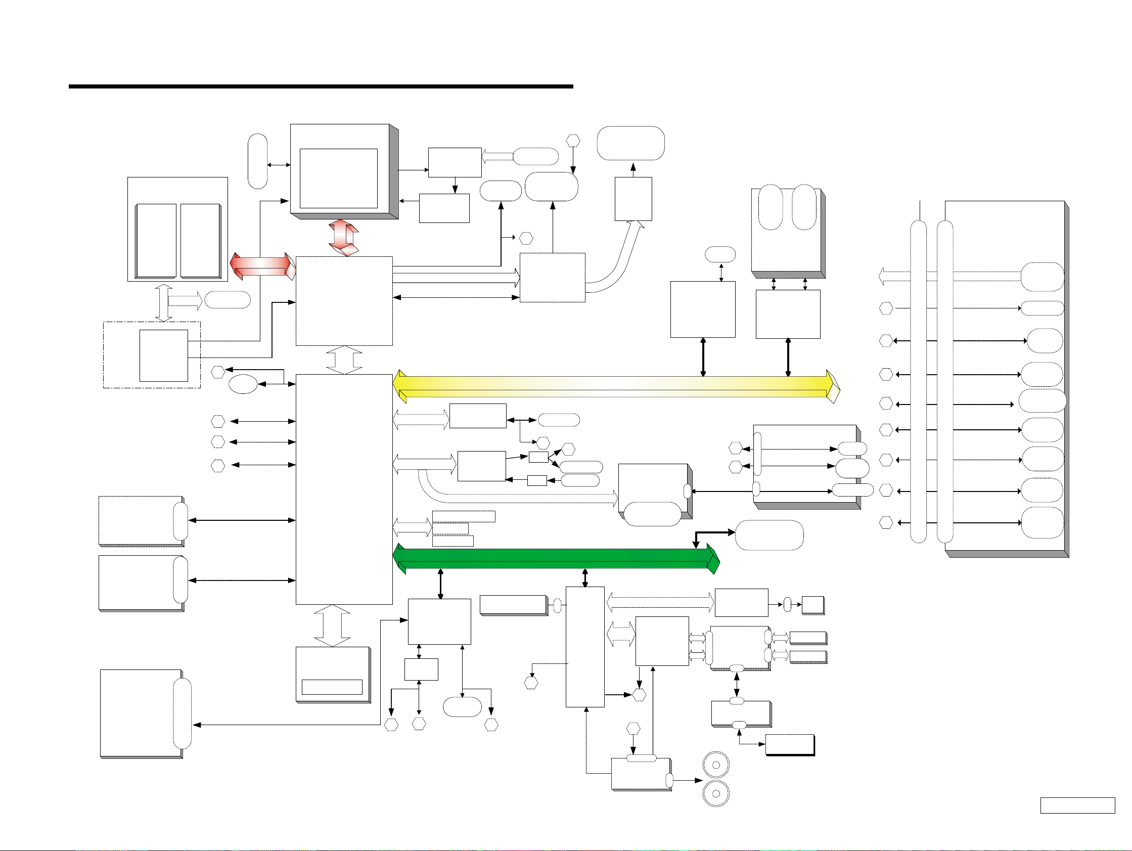
Port Replicator
CNX-125
(Touchpad BTN)
CNX-123
MODEM
MDC Module
µ-PGA2 Connector
CPU
MP III 1000/900 MHz
(Cache:256kB OD)
Memory Subsystem
PC100 SO-DIMM
SO-DIMM
Socket 2
Row# 2,3
SO-DIMM
Socket 1
Row# 0,1
P C I Bus
FW82801
VID
Selector
CPU
Volt Reg
CLK
GEN
IMI
C9835
SMBUS2
USB
PORT 0
Primary ID E
Secondary ID E
i.Link
TI
TSB43AA22PD
T
Audio
AD1881A
AC Link
Ext. MIC
Headphone
Am
p
Am
p
Ether PHY
82562ET
Cardbus
RICOH
R5C476 II
L P C
Super I/O
SMSC
LPC47N227
FDD
RS232C
Buffer
Serial
Dsub-9
Parallel
Dsub-25
MDC CN
BtoB(40pin)
EC/KBC/
SPIC
HITACHI
H8S/2149
SMBUS0
I/O Expander
/SMBUS MUX
O2micro
OZ998
TV
Encoder
CH7007A
TV-OUT
mini Jack
VGA
DSub-15
LCD
50pin CN
(LED Signal Include)
ITP Connector
Master IDE Device
Optical Devices
FPC(50pin)
Multi Purpose Bay
(FDD/2ndBattery)
SMBUS2
DVO
DVO
AHA
ATF Sense
FAN control
ADM1030
FWH
Flash BIOS ROM
AHA
viaLPC
Int. Keyboard
CN
FAN
Batter1
FW82801
HDD
BtoB CN
(50pin)
USB PORT3
LCI
SO-DIMM
Batter2
Refer to Clock Generator Block
Diagram
FW82801
SMBUS2
GMBUS
Debug Board
CN
BtoB (30pin)
VDC_IN
PCG-FX Series
BLOCK DIAGRAM Rev. 1.00
w/ Port Replicator (PCGA-PRFX1) 10/10/00
Serial
DSUB-9
Parallel
DSUB-25
USB
PORT2
VGA
4
2
3
5
1
CNX-126
DC-IN
USB
PORT3
7
100-pin Port Replicator CONNECTOR
100-pin Port Replicator CONNECTOR
RJ-45
ETHER
1
2 3
5
7
RJ-11
USB
Port 1
6
6
CN
USB PORT1
USB PORT2
i.Link
4-pin
PWS-13
(Battery CONN & Lid-
SW)
CN
CNCN
SWX-73
(PPK&SPKR C N )
CN
FW82807
Bay CN (50pin)
PC Card
Slot x2
PC Card
Socket 1
PC Card
Socket 2
FW82815
CN
CN
Stereo
Speaker
LVDS
CN
SMBUS1
9
8
8
RJ-45
4
USB
PORT0
9
10
10
CN
11
LED
PPK
Power BTN
11
CN
CN
CN
Touch pad
12
PS/2
MiniDIN-6
for KBD
12
PS/2
CLK GEN
EEPROM
for Password
CHAPTER 3.
BLOCK DIAGRAM
3-23-1
(END)
Confidential
PCG-FX777/FX877 (AM)

MEMO
CHAPTER 4.
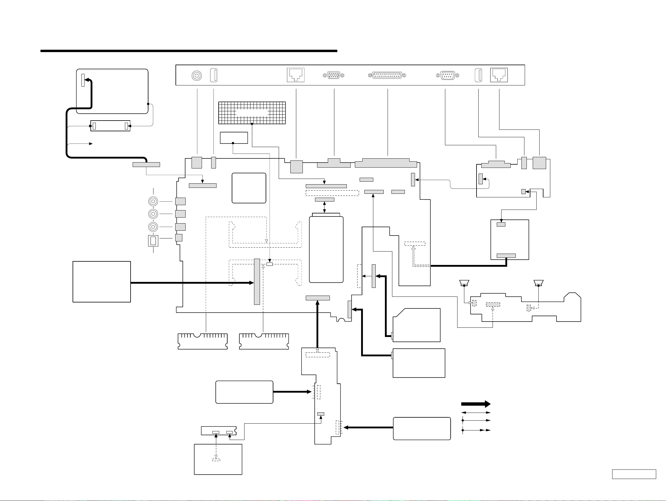
KEY BOARD
DC FAN
CPU
VIDEO OUT
EXTERNAL MICROPHONE
HEADPHONE
IEEE 1394 i.LINK
CN2801
CN1101
CN701
CN802
CN1701
CN1703
CN1301
CN1
CN502
1
250
49
Side
PC CARD
CONNECTOR
RAM
RAM
BATTERY PACK
PWS-13 Board
(Side-B)
CNX-125 Board
(Side-A)
TOUCH PAD
COMBINATION
DVD-ROM
DRIVE
FLOPPY DISK
DRIVE
2nd BATTERY PACK
(OPTION)
SWX-73
(Side-A)
MODEM CARD
MBX-49 Board
(Side-A)
J1
Speaker L Speaker R
CNX-123 Board
(Side-A)
Rear Panel
PHONEPRINTER SERIAL USB
NETWORK
MONITORDC-IN USB
LCD
INVERTER
HARD DISK
FFC LED
1
122
143
144
1
2
1
2
1
1
1
6
6
1
2
59
60
1
2
59
60
143
144
CN102
CN501
CN2701
CN4005
CN1202
1
75
150
76
FPC
FPC
CN2301
CN2302
CN4001
CN4002
49
50
50
CN4004
1
1
112 8
8
CN1502
CN702
CN1801
CN3001
CN1902
CN1401
CN2201
CN2004 CN2602
CN1802
1
1
1
1
11
1
25
2
2
2
30
29
50
49
10
8
99
100
18
CN1602
1
2
29
30
1
1
1
110
2
2
2
29
30
CN301
CN303
CN302
CN101
1
1
18
CN105
CN103
CN152
CN151
2
1
20
CN5002 CN5001
OPTION
PC100 SO-DIMM
(FX877 Model)
256MB
(FX777 Model)
128MB
From board to connector (direct connection)
Harness (connector at both end)
Harness (soldered at one end)
Connectors soldered on board and appearing on the panel
FRAME HARNESS DIAGRAM
4-24-1
(END)
Confidential
PCG-FX777/FX877 (AM)

MEMO
EXPLODED VIEWS AND PARTS LIST
NOTE:
• The mechanical parts with no reference number in the
exploded views are not supplied.
• Items marked “ * ” are not stoc ked since they are seldom
required for routine service. Some delay should be
anticipated when ordering these items.
• When two or more parts are shown in parallel, use the
part described first as the main part.
How to use properly the repair parts.
There are some parts that use the 2 types ; the [CH] parts or alternately the [JP] parts, in this series.
Use the [CH] repair parts for the [CH] type product, vice versa.
The jack and connectors mounted on the board of this model can be repaired in the [JP] type only.
And regarding the boards of [CH] type, the discrete parts on the boards cannot be replaced.
However, some connectors can be replaced.
For details, refer to “5-5.Connector Section”.
[ How to identify the parts ]
2Door DIMM
CHAPTER 5.
The components identified by mark 0 or
dotted line with mark 0 are critical for safety.
Replace only with part number specified.
Les composants identifiés par une marque
0 sont critiques pour la sécurité.
Ne les remplacer que par une pièce portant
le numéro spécifié.
1M2X4
Special Head (Black)
Identfication Seal
Serial No.
A-xxx-xxx-A x xxxxxxxxx
2 : Using [JP] type
6 : Using [CH] type
[ Repair part description example ]
Ref.No. Part No. Description
999 A-8058-171-A [CH]...MBX-49 Z3 (CH) ASSY (S)
999 A-8025-236-A [JP]...MBX-49 Z3 (JP) ASSY (S)
5-1
Identification seal is attached on the
expansion memory connector.
Confidential
PCG-FX777/FX877 (AM)
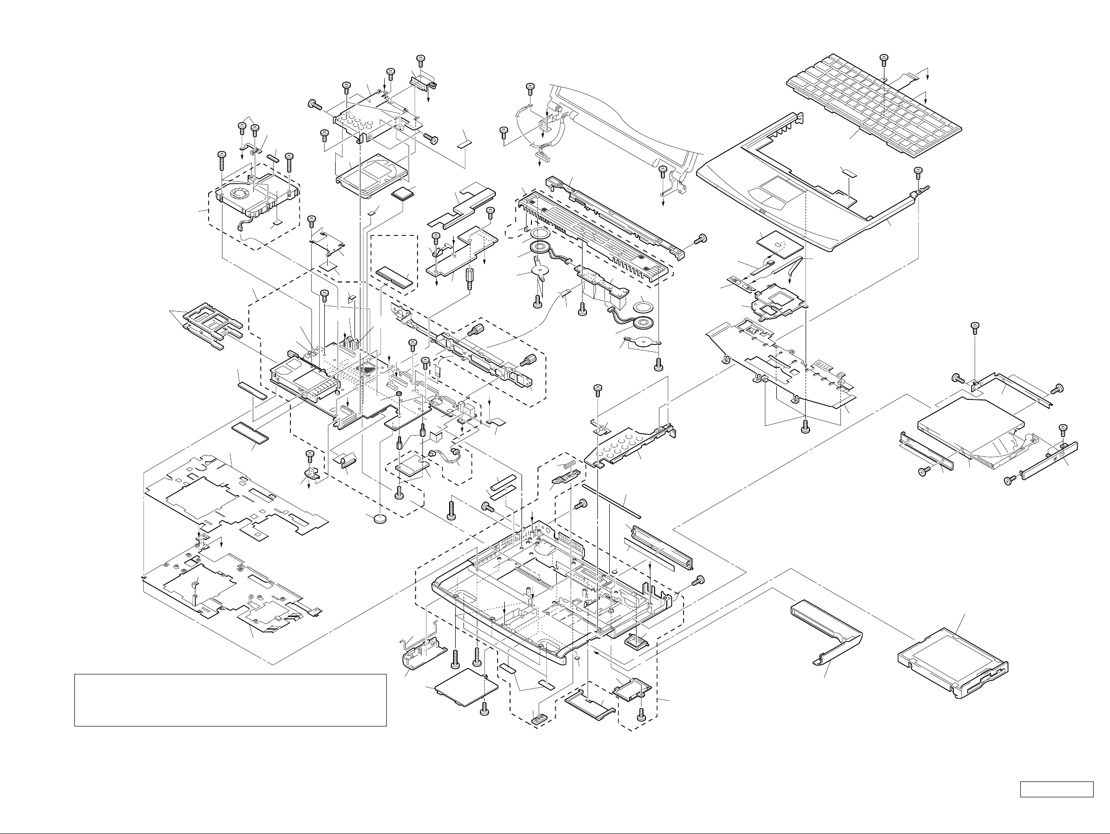
5-1. Main Section
Ref.No. Part No. Description Ref.No. Part No. Description
1 X-4623-988-1 [CH]...ASSY BOTTOM (AK)
1 X-4623-762-3 [JP]...ASSY BOTTOM (AS)
3 4-640-837-32 DOOR BATTERY
3 4-640-837-22 DOOR BATTERY
* 8 4-651-706-21 HEATSINK BOTTOM
* 8 4-651-706-01 HEATSINK BOTTOM
* 11 4-651-707-11 INSULATOR HEATSINK BOTTOM
* 11 4-651-707-21 INSULATOR HEATSINK BOTTOM
12 1-763-658-11 FAN, DC (WITH HEAT SINK)
15 4-643-832-31 DUMMY CARD
15 4-643-832-21 DUMMY CARD
18 A-8025-266-A [CH]...SWX-73 (CH) ASSY (S)
18 A-8066-960-A [JP]...COMPLETE PWB SWX-73Z3
19 X-4623-388-2 ASSY HOOD KEYBOARD (Z)
20 1-529-287-11 SPEAKER UNIT
21 3-718-233-01 NUT, PLATE
22 1-790-639-22 FPC 50PIN (FOR HDD)
24 A-8066-903-A (FX877)...ASSY HDD 20GB (H, 15F) (S)
24 A-8058-224-A (FX777)...ASSY HDD 15GB (T, 15B) (S)
25 1-476-648-71 KEY BOARD UNIT (LA)
26 X-4623-390-1 ASSY PALMREST
27 1-772-529-72 PAD, TOUCH
28 A-8025-267-A [CH]...CNX-125 (CH) ASSY (S)
28 A-8066-959-A [JP]...COMPLETE PWB CNX-125Z3
29 4-651-699-01 BRACKET PAD
* 30 4-651-708-02 BRACKET (HDD)
31 4-640-861-04 BRACKET CD-ROM R
32 1-796-072-21 COMBO DRIVE (UJDA710)
33 X-4623-436-2 ASSY DOOR DVD-RW PA
34 4-640-860-03 BRACKET (CD-ROM L)
38 4-651-713-11 [CH]...DOOR (IO) (
38 4-651-713-02 [JP]...DOOR I/O (
39 4-651-844-01 FOOT REAR
40 4-651-714-01 DOOR DOCKING CONNECTOR
41 4-640-851-11 FOOT FRONT
46 A-8025-233-A [CH]...PWS-13 (CH) ASSY (S)
46 A-8066-958-A [JP]...COMPLETE PWB PWS-13Z3
48 1-761-380-23 CARD, MODEM
52 1-790-640-11 FPC 50PIN (FOR CD-ROM)
55 4-640-845-11 BUTTON BAY
56 4-644-349-01 LATCH BAY
* 57 4-640-854-01 SPRING BAY
* 58 4-651-850-01 BRACKET BOTTOM
* 59 4-640-857-01 DOOR BATTERY SPRING
60 4-651-698-01 DISPLAY BASE
63 4-651-928-02 COVER BATTERY CONNECTOR
67 4-652-099-21 [CH]...LABEL I/O (
67 4-652-099-02 [JP]...LABEL I/O (
* 71 4-641-851-02 SPRING (FDD), PLATE
* 72 4-651-709-41 [CH]...BRACKET IO
* 72 4-651-709-01 [JP]...BRACKET IO
74 4-651-702-01 DOOR DIMM
* 76 4-644-361-01 BRACKET SPK
* 78 4-644-362-21 PLATE PALMREST
* 78 4-644-362-11 PLATE PALMREST
∗1
∗1
∗1
∗1
)
)
)
)
88 A-8058-172-A [JP]...MBX-49Z3 (JP) ASSY (S)
105 4-641-630-11 COVER BAY HOLE
123 1-790-711-21 FFC (PPK)
124 1-757-767-11 FFC (TP-CNX)
125 1-790-710-11 FFC (SWX-PWS)
* 128 4-653-452-01 PLATE, GROUND
* 134 4-645-433-01 BRACKET BAY CONNECTOR
136 4-644-357-01 CUSHION SPK
147 8-759-835-93 (FX877)...
IC KP80526GY001256 (PIII 1000 MHz)
147 6-700-454-01 (FX777)...
IC KP80526GY900256 (PIII 900 MHz)
148 X-4623-561-2 ASSY LATCH DETECTOR
* 152 4-651-871-01 HEAT SINK
153 4-652-012-01 SHEET, ELECTRIC HEAT
154 4-651-989-01 SPACER (MBX)
155 4-651-701-01 DOOR MODEM
156 4-653-151-01 SPACER (KBF)
157 4-653-466-01 CUSHION (HD-M)
159 4-653-963-01 SHIELD (CNX)
160 4-653-964-01 SPACER (B/P)
161 4-654-019-01 GASKET (AV)
162 4-654-047-01 SHIELD (AV)
163 4-653-936-01 GASKET (HB/M)
164 1-779-745-21 [JP]...JACK, DC
165 1-815-422-11 [JP]...USB CONNECTOR (VERTICAL)
166 1-695-514-21 [JP]...JACK (SMALL TYPE) 1P
167 1-815-221-21 [JP]...CONNECTOR, USB (VERTICAL)
168 1-793-430-11 [JP]...JACK, SMALL TYPE
169 4-653-962-01 SHIELD (USB)
170 4-644-667-11 COVER RJ-11
170 4-644-667-01 COVER RJ-11
171 4-654-350-01 SHEET (CPU), THERMAL
184 4-654-776-01 INSULATOR (SCREW)
185 4-658-542-01 SPACER (KEY BOARD)
186 4-654-320-21 SHEET (COIL), THERMAL
800 Refer to section “5-2. FDD Section”.
B1 4-641-726-41 SCREW (M2), SPECIAL HEAD
B3 4-644-899-01 SCREW (M2), 0 NUMBER P3 KIND
B4 4-639-112-01 SCREW M2X4
B7 4-644-402-12 SCREW (MBX)
B10 4-652-498-01 +B M2 (NOJI)
B12 4-645-177-01 SCREW (M1.7X3.5)
B14 4-645-497-01 SCREW (M2.6), CROSS (HOLE) BIND
B15 4-635-301-01 SCREW M3X4
B18 4-635-966-01 SCREW (HEX)
B31 4-645-214-11 GRIP, M2
B32 7-621-772-68 SCREW +B 2X12
B33 4-642-852-21 +B M2
B34 4-641-726-11 SCREW (M2), SPECIAL HEAD
B35 7-621-772-70 SCREW +B 2X14
B36 7-622-205-05 NUT (M2 TYPE2), HEXAGON
B40 4-641-726-11 [JP]...SCREW (M2), SPECIAL HEAD
B40 4-641-726-41 [CH]...SCREW (M2), SPECIAL HEAD
81 6-600-065-01 (FX877)...IC MT8LSDT3264HG-10EB1
81 8-749-019-00 (FX777)...IC HYM71V16M655AT6-P
81 6-600-041-01 (FX777)...IC HYM71V16M655HCT6-P
84 1-960-827-21 HARNESS (2 PIN)
88 A-8058-171-A [CH]...MBX-49Z3 (CH) ASSY (S)
(PC-100 SO-DIMM (256MB))
(PC-100 SO-DIMM (128MB CL2))
(PC-100 SO-DIMM (128MB CL2))
∗1 : When replacing the part Ref No.38 or Ref No.67, replace them together.
In addition, select the same type of the parts ([CH] type or [JP] type) as that of the original model
from which you remove the defective part.
Confidential
PCG-FX777/FX877 (AM)
5-2
15
12
A
B3
B1
B1
22
B1
B15
B33
(∗3)
B34
B1
B1
B34
E
24
152
153
169
164
(∗3)
N
not
supplied (∗2)
128
156
B3
G
171
88
168
166
(∗3)
157
11
81
134
L
52
J
30
186
FX370/
FX390
Model Only
165
B36
(∗3)
K
B40
I
81
(∗4)
154
170
B31
147
B34
148
B34
K
B15
167
(∗3)
48
F
B3
46
63
H
D
185
84
B7
162
B34
B32
L
B18
C
159
161
B34
21
20
76
136
19
B18
72
B4
B
B1
N
G
A
56
57
123
60
B14
B4
B34
20
71
18
76
38
163
(∗1)
136
58
B4
B1
C
B14
28
124
25
185
27
125
H
29
78
B34
B34
26
B10
I
J
B34
B10
34
B1
32
B12
31
B10
B12
33
B
160
8
∗1: When replacing the part Ref No.38 or Ref No.67, replace them together.
In addition, select the same type of the parts ([CH] type or [JP] type) as
that of the original model from which you remove the defective part.
∗2 Use the Sony lithium battery CR2025 or its compatible
that is available on market, for the backup battery.
∗3 [JP] type only.
∗4 Use the different types depending on [CH] or [JP] of this model.
67
(∗1)
184
E
F
59
B3
B3
3
74
B34
41
55
105
155
40
B34
39
D
B14
800 (Refer to Page 5-5.)
701 (Refer to Page 5-10.)
1
Confidential
PCG-FX777/FX877 (AM)5-3 5-4
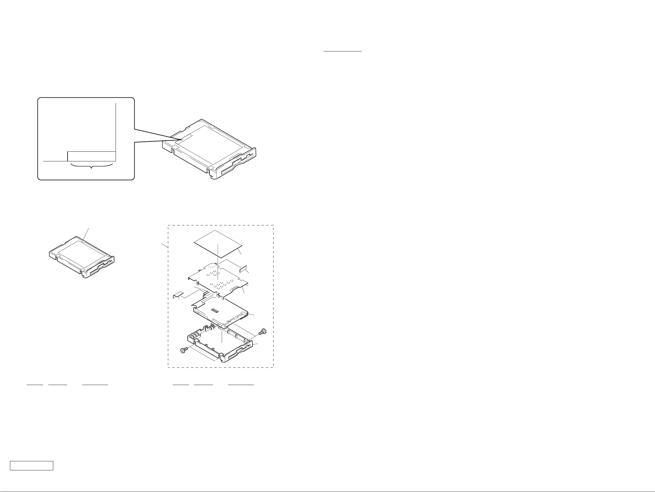
5-2. FDD Section
How to use properly the FDD repair parts.
Types of service to be provided are different depending on the serial No. of the FDD in use.
Label FD
X-XXX-XXX-XX
Serial No.
The service types are shown below depending on the serial No. that is printed in the bottom right of the FD label.
MEMO
[Serial No. : 4-656-805-0*] [Serial No. : 4-641-763-3*]
800
Ref.No. Part No. Description
800 A-8025-674-A FDD UNIT ASSY (TN-CH)
800
806
807
804
801
805
802
B1
803
B1
Ref.No. Part No. Description
800 A-8025-669-A ASSY BAY FD (TN)
801 4-640-828-01 PLATE FDD
802 1-796-231-11 FDD (FD-07-7760)
803 X-4623-835-1 ASSY BOTTOM FDD Z (TCY3)
804 1-790-641-11 FPC 50PIN (FOR FDD)
805 4-641-629-01 INSULATOR FDD
Confidential
PCG-FX777/FX877 (AM)
806 4-641-763-31 LABEL FD
807 4-644-053-01 SPACER FDD
B1 4-646-807-01 0 PLATE M2.5 (FDD)
5-5 5-6

5-3. LCD Section (FX877 Model) – Made by TS –
624
626
B30
B22
634
603
635
Ref.No. Part No. Description
601 1-476-316-11 INVERTER UNIT
602 X-4623-380-1 HINGE LEFT 15
603 X-4623-448-2 ASSY HOU, BEZEL 15SA-Z
606 4-637-902-31 LATCH
607 A-8058-271-A ASSY LCD 15XGA (TO) (S)
608 4-637-903-01 SPRING LATCH
612 X-4623-415-1 ASSY HOU,DISPLAY 15SA-Z
613 4-642-762-31 COVER HINGE (15)
614 4-658-380-11 LABEL ID (L)
619 1-757-604-11 PWB, FLEXIBLE PRINT (SINGLE)
Ref.No. Part No. Description
B8 4-641-726-11 SCREW (M2), SPECIAL HEAD
B22 4-642-761-01 +P M2X3 LOCK
B23 4-644-165-01 SCREW (M2.6X4), 0 PLATE P1 MAIN
B30 4-643-550-01 +P 2.6X6 LOCK PRECISION TYPE3
637
602
B23
B8
641(
∗1)
613
621
620
614
634
623
607
640
622
606
B22
629
608
624
B23
620 4-642-755-01 BRACKET LCD (DL) 15
621 4-642-756-01 BRACKET LCD (BL) 15
622 4-642-757-01 BRACKET LCD (DR) 15
623 4-642-758-01 BRACKET LCD (BR) 15
624 4-646-217-11 COVER SCREW SIDE (15)
625 4-635-277-22 COVER SCREW LOWER
626 4-643-549-12 COVER SCREW SHAFT
628 X-4623-381-1 HINGE RIGHT 15
629 4-643-366-11 EDGE GUARD HINGE (15)
634 4-635-276-22 COVER SCREW UPPER
635 4-642-760-12 CUSHION CENTER
637 1-961-018-71 HARNESS,LCD (XGA-F-N)
640 4-658-280-01 SHIELD TAPE (LCD)
641 FILAMENT TAPE (W12X50)(∗1)
∗1 Use the FILAMENT TAPE.
NOTE :
Set the DIP switch on the MBX-49 board (Main board) to match
with the LCD (A-8058-271-A) that is used in this computer.
N
O
1234567
The upper position where ON indication is shown is the
ON position . The lower position is the OFF position.
No.
ON/OFF
12345678
01000111
8
0 : ON 1: OFF
619
601
B8
625
5-7 5-8
613
612
628
Confidential
PCG-FX777/FX877 (AM)

5-4. LCD Section (FX777 Model) – Made by HI –
303
B20
304
B8
B8
B22
B8
319
322
325
307
305
B8
314
306
308
Ref.No. Part No. Description
301 1-476-316-21 INVERTER UNIT
302 X-4623-378-1 HINGE LEFT MV
303 X-4623-776-1 ASSY HOU, BEZEL 14H-Z
304 4-635-277-22 COVER SCREW LOWER
305 4-635-276-22 COVER SCREW UPPER
306 4-637-902-31 LATCH
307 A-8025-245-A ASSY LCD 14XGA (HT) (S)
308 4-637-903-01 SPRING LATCH
309 X-4623-379-1 HINGE RIGHT MV
312 X-4623-460-1 ASSY HOU, DISPLAY 14SA-Z
313 4-642-762-31 COVER HINGE (15)
314 4-658-380-21 LABEL ID (L)
317 1-757-605-11 PWB, FLEXIBLE PRINT (SINGLE)
319 4-654-966-01 SHEET (BEZEL), ADHESIVE
* 322 4-644-163-11 BRACKET LCD LEFT 14 (SA)
* 323 4-644-164-11 BRACKET LCD RIGHT 14 (SA)
325 4-642-760-12 CUSHION CENTER
326 1-961-018-31 HARNESS, LCD (XGA-F-N)
327 FILAMENT TAPE (W12X50)(∗1)
B8 4-641-726-11 SCREW (M2), SPECIAL HEAD
B20 7-628-254-00 SCREW +PS 2.6X5
B22 4-658-316-01 ACE (M2), +B LOCK
∗1 Use the FILAMENT TAPE.
Ref.No. Part No. Description
ACCESSORIES
************
701 A-8048-965-A ASSY WEIGHT SAVER (Z)
(Refer to P.5-4)
0 702 1-476-342-22 ADAPTOR, AC
703 1-528-935-22 (FX877)...
BATTERY PACK, LITHIUM ION
703 1-756-147-12 (FX777)...BATTERY PACK, LITHIUM ION
704 1-575-875-51 CORD, CONNECTION
0 1-757-562-21 CORD, POWER
4-658-864-11 SPEC SHEET, FX (LATIN)
4-658-869-11 QUICK START, FX (LATIN)
701
Weight saver (1)
702
AC adaptor (1)
703
Battery pack (1)
704
Video cable (1)
326
B8
317
313
302
B8
301
327(
∗1)
B20
B8
309
B8
B22
323
NOTE :
Set the DIP switch on the MBX-49 board (Main board) to match
with the LCD (A-8025-245-A) that is used in this computer.
N
O
1234567
The upper position where ON indication is shown is the
ON position . The lower position is the OFF position.
No.
ON/OFF
12345678
00100111
8
0 : ON 1: OFF
The components identified by
mark 0 or dotted line with mark
0 are critical for safety.
Replace only with part number
specified.
Les composants identifiés par
une marque 0 sont critiques
pour la sécurité.
Ne les remplacer que par une
pièce portant le numéro spécifié.
Confidential
PCG-FX777/FX877 (AM)
313
312
5-9 5-10

5-5. Connector Section (CH Type Only)
Ref.No. Fig. Part No. Description
901 1-779-745-21 [CH]...JACK, DC
DC IN connector
902 1-815-422-12 [CH]...USB CONNECTOR (VERTICAL)
USB connector
901
902
903 1-815-221-22 [CH]...CONNECTOR, USB (VERTICAL)
USB connector
∗ Among the parts that are used on the boards of this model, only the connectors that
are show in the list can be replaced.
(The parts other that the specified connectors cannot be replaced.)
903
903
903
902
902
901
901
Confidential
PCG-FX777/FX877 (AM)5-11 5-12
(END)

MEMO

MEMO

®
Notebook VAIO
Introducción rápida
PCG-FX677 /FX777/FX877
!
IMPORTANTE!
Por favor lea detalladamente este manual
de instrucciones antes de conectar y operar
este equipo. Recuerde que un mal uso
de su aparato podría anular la garantía.


Indice
Bienvenido ...................................................5
Características .............................................................5
Cómo desembalar la notebook ...................................7
Registro de la notebook ...............................................9
Configuración de la notebook VAIO........11
Localización de controles y puertos ..........................12
Conexión a una fuente de alimentación ....................17
Inicio de la notebook .................................................24
Apagado de la notebook ............................................26
Modos de ahorro de energía ......................................27
Ampliación de la memoria de su
notebook VAIO ..........................................29
Precauciones y procedimientos .................................30
Para extraer un módulo de memoria .........................32
Instalación del módulo de memoria. .........................34
Visualización de la cantidad de memoria..................36
Acerca del software incluido en
la notebook ................................................37
Descripción general del software ..............................38
3

Notebook VAIO® Introducción rápida
Discos compactos de recuperación de
aplicaciones y sistema............................................... 42
Recuperación del sistema.......................................... 43
Resolución de problemas ........................47
Resolución de problemas de la notebook ................ 48
Resolución de problemas de la pantalla LCD........... 52
Resolución de problemas del mouse y
del panel táctil ........................................................... 54
Resolución de problemas de unidades, tarjetas de
PC y dispositivos periféricos ................................... 56
Resolución de problemas de software ..................... 59
Resolución de problemas del módem ....................... 61
Resolución de problemas de sonido.......................... 62
Resolución de problemas de la impresora ................ 63
Cómo obtener ayuda ................................65
Opciones de soporte.................................................. 66
Información de soporte de software.......................... 67
Index...........................................................69
4

Bienvenido
Felicitaciones por la compra de la Notebook todo en uno VAIO® de Sony.
Sony ha combinado tecnología de punta en audio, vídeo, informática y
comunicaciones con el objeto de presentarle una computadora personal
de vanguardia.
Características
Para obtener una descripción completa de las especificaciones de su notebook
✍
®
VAIO
, consulte el impreso de especificaciones provisto con la notebook.
*
Rendimiento excepcional — Su notebook incluye un procesador Intel®
❑
que incorpora la tecnología más moderna, así como un módem compatible
V. 9 0 / K 5 6 f l e x .
Para optimizar el rendimiento y portabilidad, Sony ha implementado la
tecnología de control de velocidad diseñada para maximizar la vida de la
batería durante el uso en movimiento de la computadora. Windows®
informó que es posible que la velocidad real del CPU no refleje la velocidad
máxima.
†
‡
Portabilidad — El paquete de baterías recargables proporciona horas de uso
❑
sin conexión a la red eléctrica.
Calidad Sony en audio y vídeo — Vídeo de alta calidad MPEG1/MPEG2,
❑
que admite visualización en pantalla completa y permite sacar el máximo
partido de las aplicaciones multimedia, los juegos y el software de
entretenimiento más avanzados de hoy en día.
* La velocidad del CPU disminuirá bajo ciertas condiciones de operación .
† La velocidad real de carga y descarga de archivos puede variar según las condiciones de la
línea, el proveedor de servicios de Internet (ISP) y la legislación gubernamental.
‡ Según el modelo específico que adquirió, puede que no exista tecnología de control de
velocidad.
5

Notebook VAIO® Introducción rápida
Características multimedia — Disfrute de los altavoces estéreo o use
❑
auriculares (no incluidos) para escuchar CD de audio y vídeo.
Sistema operativo Windows®de Microsoft® — Su sistema incluye la
❑
última versión del sistema operativo Windows® de Microsoft®.
Comunicaciones — Acceda a los servicios en línea más conocidos, envíe
❑
mensajes de correo electrónico, navegue por Internet y utilice las funciones
de fax.
Unidad de disco óptico (CD-RW/DVD o DVD-ROM) — La unidad
❑
combinada de CD-RW/DVD utiliza una nueva tecnología de
almacenamiento óptico que combina las características de una unidad de
CD-RW y de una unidad de DVD-ROM, lo cual da como resultado una
mayor capacidad de almacenamiento junto con una experiencia multimedia
más intensa. Las unidades ópticas reproducen discos DVD-ROM, CD-ROM,
CD-RW y CD-R. (La unidad combinada CD-RW/DVD sólo está disponible
con algunos modelos.)
La unidad de disco óptico y otros componentes pueden variar según el modelo
✍
específico de notebook que haya adquirido.
6

Cómo desembalar la notebook
Cómo desembalar la notebook
Extraiga de la caja los elementos de hardware siguientes:
Unidad principal
*
Cable de alimentación
Adaptador de CA
Cable de vídeo Paquete de
baterías recargable
* La unidad de disquete extraíble se encuentra en el compartimento multifunción.
Protector de
carga
Documentos
Guía del usuario de la notebook VAIO® — Un archivo de ayuda
❑
explorable en línea que contiene información detallada sobre el modo de uso
de su nueva notebook. Vaya a Inicio, seleccione VAIO Help and Support
(Soporte y ayuda de VAIO) y haga clic en la Guía del usuario VAIO para
abrir este archivo.
Introducción rápida a la notebook VAIO® — Contiene información sobre
❑
cómo desembalar y configurar la notebook, las características de la
notebook, las aplicaciones incluidas en el sistema y cómo solucionar los
problemas más comunes.
7

Notebook VAIO® Introducción rápida
Guía Introducción de Windows® de Microsoft® — Explica cómo utilizar
❑
las funciones básicas del último sistema operativo de Windows.
Información sobre seguridad — Incluye notas sobre uso y ofrece consejos
❑
de seguridad.
Volante de especificaciones — Detalla las especificaciones del hardware de
❑
la notebook.
CD de recuperación
CD de recuperación de aplicaciones — Este CD le permite volver a
❑
instalar aplicaciones individuales en caso de que se hayan dañado o borrado.
CD de recuperación del sistema — Este CD le permite formatear la
❑
partición C:\ de la unidad de disco duro, volver a instalar luego el sistema
operativo y el software que se entregó junto con su notebook, en caso de que
se hubieran dañado o borrado.
Otros
Paquete con ofertas especiales de productos
❑
Tarjeta de garantía limitada
❑
8

Registro de la notebook
Registro de la notebook
Disfrute de los beneficios del compromiso asumido por Sony de brindar una
asistencia al cliente de calidad registrando su notebook:
Servicio al cliente de Sony — Póngase en contacto con un representante de
❑
asistencia al cliente para resolver los problemas que se le presenten al
utilizar su notebook.
Garantía limitada — Proteja su inversión. Lea la tarjeta de garantía para
❑
obtener más detalles.
Se le pide que registre su computadora la primera vez que enciende la unidad. Siga las
✍
instrucciones en pantalla para completar el proceso de registro. Si no puede registrar
su computadora durante la primera sesión, se le ofrece la oportunidad de hacerlo en
ocasiones posteriores.
9

Notebook VAIO® Introducción rápida
10

Configuración de la
notebook VAIO
Esta sección describe lo siguiente:
Localización de controles y puertos
❑
Conexión a una fuente de alimentación
❑
Inicio de la notebook
❑
Apagado de la notebook
❑
Modos de ahorro de energía
❑
11

Notebook VAIO® Introducción rápida
Localización de controles y puertos
Parte frontal
+
1 Pantalla LCD (pantalla de
7 Indicadores de batería 1 y 2
cristal líquido)
2 Altavoces 8 Indicador de la unidad de disco
duro
3 Teclado 9 Indicador Bloq Num
4 Panel táctil 10 Indicador Bloq Mayús
5 Botones izquierdo y derecho 11 Indicador Bloqueo Despl
6 Indicador de encendido
12

Izquierda
Localización de controles y puertos
1 Conector de salida de TV 4 Puerto i.LINK® (IEEE1394)
*
S400
2 Conector de micrófono 5 Ranura para tarjetas de PC
3 Conector de auriculares 6 Compartimento de baterías
* i.LINK es una marca comercial de Sony que se utiliza únicamente para indicar que un
producto contiene un conector IEEE1394. La conexión i.LINK puede variar, según cuáles
sean las aplicaciones de software, el sistema operativo y los dispositivos compatibles con
i.LINK. No todos los productos con un conector i.LINK pueden comunicarse entre sí.
Consulte la documentación original del dispositivo compatible con i.LINK si desea
información sobre las condiciones de operación y la conexión. Antes de conectar
dispositivos periféricos compatibles con i.LINK a su sistema –por ejemplo, una unidad de
CD-RW o de disco duro– confirme su compatibilidad con el sistema operativo y las
condiciones de funcionamiento exigidas.
13

Notebook VAIO® Introducción rápida
Derecha
1 Botones PPK
2 Botón de encendido
3 Unidad óptica (Unidad combinada de CD-RW/DVD o unidad de DVD-
ROM
*
)
4 Compartimento multifunción
* El tipo de unidad óptica varía según el modelo específico que usted haya adquirido.
14

Parte posterior
Localización de controles y puertos
cubierta
1 Puerto de módem 5 Puerto de monitor
2 Puertos USB 6 Puerto Ethernet
3 Puerto serie 7 Puerto de entrada CC
4 Puerto de impresora
Conecte únicamente cables 10BASE-T y 100BASE-TX al puerto Ethernet. No
conecte ningún otro tipo de cable de red ni ninguna línea de teléfono. Si
conecta cables distintos de los indicados se puede producir una sobrecarga
de corriente eléctrica que ocasione un fallo, calor excesivo o queme el
puerto. Para conectar la unidad a la red, póngase en contacto con el
administrador de la red.
Existe una ranura de ventilación situada entre el puerto Ethernet y el puerto USB CC.
✍
No cubra la ranura de ventilación cuando la notebook está encendida.
15

Notebook VAIO® Introducción rápida
Parte inferior
1 Palanca de liberación del compartimento multifunción
2 Soportes de inclinación
16

Conexión a una fuente de alimentación
Conexión a una fuente de alimentación
Puede utilizar como fuente de alimentación una toma de CA o un paquete de
baterías recargable.
Uso del adaptador de CA
1 Enchufe el cable conectado al adaptador de CA en el puerto de entrada de
CC de la notebook.
2 Enchufe un extremo del cable de alimentación en el adaptador de CA.
3 Enchufe el otro extremo del cable de alimentación en la toma de CA.
Conexión del adaptador de CA
Notebook
Entrada de CC
Adaptador de CA
(suministrado)
Cable de alimentación
(suministrado)
Notas acerca del adaptador de CA
La notebook funciona a 100V-240V CA, 50/60 Hz.
❑
La notebook no debe compartir la toma de CA con otros equipos que
❑
consumen energía, tales como máquinas fotocopiadoras o trituradoras de
papel.
Puede adquirir una regleta con un protector contra picos de tensión. Este
❑
dispositivo evita daños en la notebook causados por picos repentinos de
tensión, como los que pueden producirse durante las tormentas eléctricas.
No coloque objetos pesados sobre el cable de alimentación.
❑
Para desconectar el cable, tire de él tomándolo por el enchufe. No tire nunca
❑
del propio cable.
17

Notebook VAIO® Introducción rápida
Desenchufe la notebook de la toma de la pared si no va a utilizarla por un
❑
tiempo prolongado.
Es posible que el indicador LED del adaptador de CA quede encendido hasta
❑
que se desenchufe el adaptador de la notebook.
Cuando no esté utilizando el adaptador de CA, desenchúfelo de la toma de la
❑
pared.
Utilice sólo el adaptador de CA suministrado. No utilice ningún otro
❑
adaptador de CA.
Uso de la alimentación por batería
Puede utilizar uno o dos paquetes de baterías como fuente de alimentación. El
segundo paquete de baterías se inserta en el compartimento multifunción situado
en el lado derecho de la notebook. (Consulte “Uso de un paquete de baterías
secundario” en la Guía del usuario en línea para obtener más información.) Como
opción, están disponibles paquetes de baterías adicionales.
El paquete de baterías que se incluye con la notebook no está totalmente cargado
en el momento de la adquisición. Siga los pasos que se indican a continuación
para insertar y cargar el paquete de baterías.
Para insertar el paquete de baterías
1 Busque el compartimento de baterías del lado izquierdo de la notebook y
presione la tapa para abrirlo.
La tapa se abre hacia afuera sin desprenderse.
✍
Compartimento de baterías
18

Conexión a una fuente de alimentación
2 Inserte el paquete de baterías en el compartimento de baterías.
Inserción del paquete de baterías
Paquete de baterías
(suministrado)
La cara que lleva la etiqueta
debe quedar hacia abajo.
3 Presione la tapa del compartimento de baterías hasta que se oiga un clic.
Si el duplicador de puertos está adosado a la notebook, no intente insertar ni extraer el
✍
paquete de baterías. Si se levanta y se gira la notebook con un duplicador de puerto
conectado, podría producirse una pérdida de alimentación temporaria.
Para cargar el paquete de baterías
1 Conecte el adaptador de CA a la notebook.
2 Inserte el paquete de baterías
La notebook carga la batería en forma automática. El indicador de batería se
enciende intermitentemente con un parpadeo doble mientras se carga la
batería.
3 Cuando la batería está cargada al 85%, el indicador de batería se apaga. Si la
notebook está encendida, el proceso lleva 1,5 hora.
Para cargar la batería completamente, continúe cargando durante una hora más.
✍
Consulte “Visualización de información sobre baterías” en la Guía del usuario en línea
para obtener más información.
19

Notebook VAIO® Introducción rápida
Hay dos indicadores de batería en la notebook.
Indicadores de baterías
Indicadores de batería
Indicador de batería Descripción
1
Indica el estado del paquete de baterías situado en el
compartimento de baterías del lado izquierdo de la
notebook.
2
Indica el estado del paquete de baterías situado en el
compartimento multifunción del lado derecho de la
notebook.
Estado del indicador
luminoso de batería Descripción
Encendido La notebook está utilizando alimentación por batería.
Parpadeo sencillo La batería se está agotando.
Parpadeo doble La batería se está cargando.
Apagado La notebook está utilizando alimentación de CA.
20

Conexión a una fuente de alimentación
Para extraer el paquete de baterías
1 Abra la tapa del compartimento de baterías.
2 Tire del paquete de baterías.
Extracción del paquete de baterías
3 Presione la tapa del compartimento de baterías hasta que se oiga un clic.
Si extrae el paquete de baterías mientras la notebook está encendida y no se
encuentra conectada al adaptador de CA, o si extrae la batería cuando la
notebook se encuentra en el modo de ahorro de energía, perderá datos.
Notas acerca de la batería
Consulte “Visualización de información sobre baterías” en la Guía del
❑
usuario en línea para obtener información sobre la carga que resta en la
batería.
Cuando la batería se está agotando, parpadean ambos indicadores, el de
❑
batería y el de encendido.
Cuando la notebook está conectada directamente a la alimentación de CA y
❑
tiene el paquete de baterías en el compartimento de batería, utiliza
alimentación de la toma de CA.
Consulte “Uso de un paquete de baterías secundario” en la Guía del usuario
❑
en línea para obtener información acerca de cómo instalar y cargar un
paquete de baterías en el compartimento multifunción.
21

Notebook VAIO® Introducción rápida
Deje el paquete de baterías en la notebook cuando esté directamente
❑
conectada a la alimentación de CA. El paquete de batería sigue cargándose
mientras está utilizando la notebook.
Si el nivel de carga de la batería cae por debajo del 10%, deberá conectar el
❑
adaptador de CA para recargarla o apagar la notebook e insertar una batería
totalmente cargada.
Puede ampliar la vida útil de la batería cambiando los modos de
❑
administración de la alimentación en la utilidad PowerPanel. Consulte
“Modos de ahorro de energía” en la página 27 si desea más información.
El paquete de baterías suministrado con la notebook es de iones de litio y
❑
puede recargarse en cualquier momento. Cargar una batería parcialmente
descargada no afecta la vida útil de la batería.
El indicador de la batería está encendido cuando utiliza el paquete de
❑
baterías como fuente de alimentación. Cuando está a punto de agotarse la
vida de la batería, comienza a parpadear el indicador de batería.
Con algunas aplicaciones de software y algunos dispositivos periféricos, la
❑
notebook puede no entrar en el modo Hibernación cuando la carga de la
batería está baja. Para evitar pérdida de datos al utilizar alimentación por
batería, deberá guardar los datos con frecuencia y activar manualmente un
modo de administración de energía, como Inactivo o Hibernación.
No exponga nunca el paquete de baterías a temperaturas superiores a 140º F
❑
(60º C), como puede suceder bajo la luz solar directa o dentro de un coche
aparcado al sol.
La vida de la batería es más corta en un ambiente frío. Esto se debe a que el
❑
rendimiento de las baterías disminuye a temperaturas bajas.
Cargue las baterías a temperaturas comprendidas entre 50° F y 80° F (10° C
❑
y 30° C). Las temperaturas más bajas exigen mayor tiempo de carga.
Mientras la batería está en uso o se está descargando, el paquete de baterías
❑
aumenta de temperatura. Esto es normal y no es motivo para preocuparse.
Mantenga el paquete de baterías alejado de fuentes de calor.
❑
Mantenga seco el paquete de baterías.
❑
No abra ni trate de desmontar el paquete de baterías.
❑
22

Conexión a una fuente de alimentación
No exponga el paquete de baterías a ningún choque mecánico.
❑
Si no va a utilizar la notebook durante un período prolongado, extraiga el
❑
paquete de baterías para evitar que se dañe.
Si después de cargar totalmente el paquete de baterías, el nivel de carga de la
❑
batería sigue bajo, puede ser que esté llegando al final de su vida útil y deba
ser sustituido.
No necesita descargar la batería antes de recargarla.
❑
Si no ha utilizado el paquete de baterías por un período de tiempo
❑
considerable, vuelva a cargarlo.
23

Notebook VAIO® Introducción rápida
Inicio de la notebook
1 Deslice la palanca de bloqueo de la pantalla LCD en la dirección de la flecha
y levante la tapa.
Apertura de la notebook
Palanca de bloqueo de la pantalla LCD
2 Pulse el botón de encendido situado en la parte superior de la notebook hasta
que se encienda el indicador de encendido (color verde).
Botón de encendido
Indicador de encendido
Si mantiene el botón de encendido en la posición de encendido durante más de cuatro
✍
segundos, la notebook se apaga.
Botón de encendido
24

Inicio de la notebook
3 Si fuera necesario, ajuste los controles de brillo para la pantalla LCD de la
siguiente manera:
Para disminuir el brillo, pulse Fn+F5 y, a continuación, la tecla de
❑
flechas hacia abajo o hacia la izquierda.
Para aumentar el brillo, pulse Fn+F5 y, a continuación, la tecla de
❑
flechas hacia arriba o hacia la derecha.
25

Notebook VAIO® Introducción rápida
Apagado de la notebook
Para evitar posibles pérdidas de datos, siga estos pasos para apagar la
notebook.
1 Haga clic en Inicio en la barra de tareas de Windows®.
2 Haga clic en Apagar en la parte inferior del menú Inicio para mostrar el
cuadro de diálogo Apagar el sistema.
3 Seleccione Apagar.
Responda a cualquier mensaje que le indique que debe guardar los documentos.
✍
4 Espere hasta que la notebook se apague automáticamente. La notebook está
apagada cuando el indicador de encendido se apaga.
5 Apague todos los dispositivos periféricos conectados a la notebook.
Durante un período de inactividad, puede prolongar la vida de la batería utilizando el
✍
modo Inactivo. Consulte “Control de la administración de energía” en la Guía del
usuario en línea para obtener más información.
Si no puede apagar la notebook:
1 Cierre o finalice todas las operaciones según se indica a continuación:
Cierre todas las aplicaciones.
❑
Extraiga las tarjetas de PC.
❑
Desconecte todos los dispositivos USB.
❑
2 Reinicie la notebook. Puede reiniciar la notebook pulsando las teclas
Ctrl+Alt+Supr en forma simultánea.
Si sigue sin poder apagar la notebook, puede pulsar el botón de encendido y
✍
mantenerlo pulsado más de cuatro segundos. Esta operación puede provocar la
pérdida de datos.
26

Modos de ahorro de energía
Modos de ahorro de energía
Cuando utilice una batería como fuente de alimentación para la notebook, puede
recurrir a la función de administración de energía para prolongar la duración de la
batería. Además del modo de funcionamiento normal, que permite desconectar
dispositivos específicos, la notebook tiene dos modos diferentes de ahorro de
energía: Inactivo e Hibernación. Cuando utilice alimentación por batería, tenga en
cuenta que la notebook entra automáticamente en modo Hibernación cuando la
carga de la batería está por debajo del 5%, independientemente del modo de
administración de energía seleccionado.
Si el nivel de carga de la batería cae por debajo del 10%, deberá conectar el adaptador
✍
de CA para recargarla o apagar la notebook e insertar una batería totalmente cargada.
Modo normal
El modo normal es el estado en que normalmente se usa la notebook. El
indicador de encendido tiene color verde cuando la notebook está en este modo.
Para ahorrar energía, puede apagar un dispositivo específico como la pantalla
LCD o el disco duro.
Modo Inactivo
En el modo Inactivo, la notebook guarda el estado actual del sistema en la
memoria RAM y desconecta la alimentación a la CPU. En este modo, la luz de
color ámbar del indicador de encendido parpadea.
Para activar el modo Inactivo
Para activar el modo Inactivo, pulse la combinación de teclas Fn+Esc. También
puede usar la utilidad PowerPanel para entrar en el modo Inactivo.
Para volver al modo normal
Pulse cualquier tecla para volver al modo normal.
Modo Hibernación
En el modo Hibernación, el estado del sistema se guarda en la unidad de disco
duro y se desactiva la alimentación. El indicador de encendido queda apagado.
27

Notebook VAIO® Introducción rápida
Para activar el modo Hibernación
Para activar el modo Hibernación, pulse la combinación de teclas Fn+F12, o
pulse el botón de encendido y suéltelo inmediatamente.
No mueva la notebook hasta que el indicador de encendido se apague.
✍
Para volver al modo normal
Para volver al modo normal, encienda la notebook pulsando el botón de
encendido. La notebook vuelve a su estado anterior.
Cuando se vuelve del modo Hibernación, el estado del sistema almacenado en el disco
✍
duro se borra y la notebook inicia su funcionamiento normalmente si se pulsa el botón
de encendido durante más de cuatro segundos.
Tiempo necesario para volver al modo normal
❑
Se tarda menos en volver al modo normal del modo Inactivo que del modo
Hibernación.
Consumo energético
❑
En el modo Inactivo se consume más energía que en el modo Hibernación.
28

Ampliación de la memoria
de su notebook VAIO
Es posible que más adelante desee instalar módulos de memoria para
ampliar las funciones de su notebook. La cantidad de memoria con que
contará su notebook dependerá del modelo que haya adquirido. Consulte
la hoja de especificaciones provisto con la computadora para averiguar
la cantidad de memoria preinstalada. Los módulos de ampliación de
memoria están disponibles como opción. Para ampliar la memoria, use
exclusivamente módulos PC100(CL2) SDRAM SO-DIMM (contactos de
plomo dorados). Esta sección describe los pasos necesarios para
reemplazar módulos de memoria en su computadora.
Precauciones y procedimientos
❑
Para extraer un módulo de memoria
❑
Instalación del módulo de memoria.
❑
Visualización de la cantidad de memoria
❑
29

Notebook VAIO® Introducción rápida
Precauciones y procedimientos
Los procedimientos descritos a continuación presuponen que el usuario está
familiarizado con la terminología general asociada con las computadoras
personales, así como con las prácticas de seguridad habituales requeridas para el
uso y modificación de equipos electrónicos. Podrían producirse lesiones
personales o daños en el equipo si no se toman estas precauciones.
Al instalar módulos de memoria en su notebook, tome las precauciones de
seguridad que correspondan. Consulte la lista incluida a continuación.
Cuando agregue módulos de memoria, sea cuidadoso: los errores
cometidos al instalar o retirar un módulo pueden ser causas de fallos.
Desconecte el sistema de la fuente de alimentación y de todos los enlaces de
❑
telecomunicaciones, redes o módems antes de abrir el sistema.
Las descargas electrostáticas (ESD) pueden dañar los módulos de memoria y
❑
otros componentes. Lleve a cabo los procedimientos que se describen a
continuación sólo en un puesto de trabajo ESD. Si no está disponible un
puesto de este tipo, no trabaje en una zona con moqueta ni manipule
materiales que produzcan o retengan electricidad estática (envoltorios de
celofán, por ejemplo). Conéctese a tierra manteniendo contacto con una
parte metálica del chasis que no esté pintada mientras lleva a cabo el
procedimiento.
No abra el paquete del módulo de memoria hasta que esté preparado para
❑
instalar el módulo. El embalaje protege el módulo de las descargas
electrostáticas.
Use la bolsa especial para evitar las descargas electrostáticas o utilice papel
❑
de aluminio cuando almacene el módulo de memoria.
30

Precauciones y procedimientos
Configuración típica de ampliación de memoria
Para determinar la cantidad exacta de memoria preinstalada en su computadora,
consulte el volante de Especificaciones provisto con la notebook.
Según el modelo específico que haya adquirido, puede que se haya instalado
✍
previamente un sólo módulo de memoria de 256 MB o dos de 128 MB.
Modelos con 128 MB de memoria
Memoria total del sistema
(MB) Ranura 1 (MB) Ranura 2 (MB)
128 128
192 128 64
256 128 128
*
384
*
512
* Las configuraciones de 384 MB y 512 MB de memoria pueden hacer necesario extraer y
reemplazar los módulos de memoria originales instalados en fábrica.
256 128
256 256
Modelos con 256 MB de memoria
Memoria total del sistema
(MB) Ranura 1 (MB) Ranura 2 (MB)
*
256
†
384
†
512
* Según el modelo específico que adquirió, puede que se haya instalado previamente un
módulo de memoria de 256 MB o uno de 128 MB.
† Las configuraciones de 384 MB y 512 MB de memoria pueden hacer necesario extraer y
reemplazar los módulos de memoria originales instalados en fábrica.
256
256 128
256 256
31

Notebook VAIO® Introducción rápida
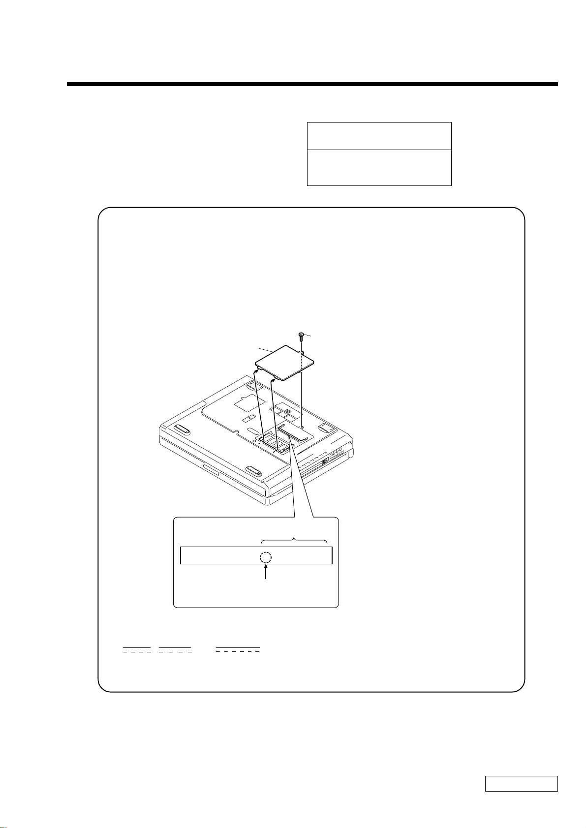
Para extraer un módulo de memoria
1 Apague la notebook y desconecte todos los dispositivos periféricos, como la
impresora.
2 Desenchufe la notebook y retire los paquetes de baterías.
3 Cuando la computadora se enfríe, afloje y extraiga el tornillo que fija la tapa
del compartimento de memoria ubicada en la cara inferior de la notebook.
Use un destornillador adecuado.
Extracción de la tapa del módulo de memoria
Destornillador
Destornille
4 Toque un objeto metálico (por ejemplo, el panel de conectores de la parte
posterior de la notebook) para descargar la electricidad estática.
32

Para extraer un módulo de memoria
5 Extraiga el módulo de memoria.
Extracción del módulo de memoria
1
2
1
1 Tire de las lengüetas en la dirección de las
flechas. El módulo de memoria ya está suelto.
2 Tire del módulo de memoria en
la dirección de la flecha.
6 Vuelva a colocar la tapa del compartimento de memoria.
7 Apriete el tornillo de la tapa.
33

Notebook VAIO® Introducción rápida
Instalación del módulo de memoria.
1 Apague la notebook y desconecte todos los dispositivos periféricos, como la
impresora.
2 Desenchufe la notebook y retire los paquetes de baterías.
3 Cuando la computadora se enfríe, afloje y extraiga el tornillo que fija la tapa
del compartimento de memoria ubicada en la cara inferior de la notebook.
Use un destornillador adecuado.
Extracción de la tapa del módulo de memoria
Destornillador
Destornille
4 Toque un objeto metálico (por ejemplo, el panel de conectores de la parte
posterior de la notebook) para descargar la electricidad estática.
5 Extraiga el módulo de memoria de su embalaje.
6 Deslice el módulo de memoria en la ranura vacía
34

Instalación del módulo de memoria.
7 Presione el módulo en su lugar hasta que se oiga un clic.
Instalación del módulo de memoria
1 Deslice el módulo de memoria en la ranura.
1
2 Presione el módulo en su lugar hasta que se oiga un clic.
2
8 Vuelva a colocar la tapa del compartimento de memoria.
9 Apriete el tornillo de la tapa.
35

Notebook VAIO® Introducción rápida
Visualización de la cantidad de memoria
1 Reinicie la notebook.
2 Haga clic en la barra de tareas de Windows®, seleccione Soporte y Ayuda, y
haga clic en "Sony Notebook Setup" (Configuración de la notebook de
Sony). Aparecerá la pantalla Sony Notebook Setup (Configuración de la
notebook de Sony).
3 Haga clic en la ficha “About This Computer” (Acerca de esta computadora)
para ver la cantidad de memoria del sistema. Si no apareciera la memoria
agregada, repita los pasos descritos anteriormente.
La cantidad de memoria que se muestra en la pantalla Sony Notebook Setup
✍
(Configuración de la notebook de Sony) no siempre es la correcta. El adaptador de
vídeo utiliza parte de la memoria del sistema, y esa cantidad de memoria no aparece
como parte de la memoria total que se muestra en la pantalla Sony Notebook Setup
(Configuración de la notebook de Sony).
36

Acerca del software incluido
en la notebook
La notebook VAIO® está preparada para ayudarle a trabajar, jugar,
aprender y comunicarse en cuanto usted la enciende. En esta sección,
encontrará la siguiente información:
Una descripción general de los diversos sistemas de software que
❑
acompañan la notebook y de las actividades que puede llevar a cabo con
ellos
Información detallada sobre los discos compactos de recuperación de
❑
aplicaciones, controladores y sistema de Sony.
37

Notebook VAIO® Introducción rápida
Descripción general del software
Dependiendo de la configuración que haya comprado, es posible que en su
computadora no estén instaladas todas las aplicaciones de software que se
mencionan a continuación.
Adobe Acrobat® Reader™
Adobe Systems Inc.
El software Acrobat Reader permite ver, navegar e imprimir documentos
electrónicos en formato PDF (Adobe Portable Document Format), un formato de
archivo abierto que sirve para preservar la fidelidad de los documentos creados
en todas las plataformas informáticas más importantes.
QuickTime™
Apple Computer Inc.
QuickTime es la tecnología de Apple que da vida a los vídeos, al sonido, la
música, las imágenes tridimensionales y la realidad virtual cuando se utiliza el
explorador de Internet y Windows.
DigitalPrint
Sony Electronics Inc.
Este software para gestión de imágenes vuelve fácil y divertida la tarea de editar,
importar y organizar las fotografías digitales en un álbum fotográfico que le
permitirá lograr una impresión digital de calidad con cualquier impresora en
color láser o de chorro de tinta. DigitalPrint también puede utilizarse para hacer
etiquetas de CD personalizadas para sus discos compactos de audio.
38

Descripción general del software
DVgate™
Sony Electronics Inc.
*
Conecte una grabadora de vídeo digital al conector i.LINK®
y grabe sus propios
clips de vídeo e imágenes fijas. Puede editar clips de su vídeo, añadir otros y
combinar clips en nuevos segmentos de película. También puede guardar sus
imágenes en diversos formatos de archivo conocidos.
Internet Explorer de Microsoft®
Microsoft Corp.
Internet Explorer pone Internet a su alcance justo como usted desea. Es seguro,
fácil de utilizar y permite personalizar la forma de acceso a la Red. Outlook
Express y otras herramientas de Internet Explorer también constituyen elementos
que mejoran su experiencia a la hora de utilizar la Red.
MovieShaker™
Sony Electronics Inc.
El software MovieShaker original de Sony crea películas personales que tienen
transiciones, música de fondo y texto. Sólo tiene que importar clips de vídeo y
“agitar” con un clic del mouse. Las películas personales son de fácil creación y
resultan divertidas para compartir con la familia y los amigos.
Norton AntiVirus™ (Sólo en algunos modelos)
Symantec Corporation
Norton AntiVirus le proporciona seguridad en lo que atañe a sus comunicaciones
por Internet y por correo electrónico. Este potente software antivirus trabaja en
segundo plano para proteger permanentemente su computadora, explorando los
archivos que descarga de la Red y los que recibe como adjuntos de mensajes de
correo electrónico. Cada vez que usted se conecta a Internet, Norton Antivirus
actualiza las definiciones de virus para darle protección automática hoy y
siempre.
* i.LINK es una marca comercial de Sony que se utiliza únicamente para indicar que un
producto contiene un conector IEEE1394. La conexión i.LINK puede variar, según cuáles
sean las aplicaciones de software, el sistema operativo y los dispositivos compatibles con
i.LINK. No todos los productos con un conector i.LINK pueden comunicarse entre sí.
Consulte la documentación original del dispositivo compatible con i.LINK si desea
información sobre las condiciones de operación y la conexión. Antes de conectar dispositivos
periféricos compatibles con i.LINK a su sistema –por ejemplo, una unidad de CD-RW o de
disco duro– confirme su compatibilidad con el sistema operativo y las condiciones de
funcionamiento exigidas.
39

Notebook VAIO® Introducción rápida
PictureGear™
Sony Electronics Inc.
Este software de gestión de imágenes muestra imágenes almacenadas en el disco
duro, de una cámara fija digital de Sony o de una cámara Sony Mavica®. Las
imágenes aparecen en un formato práctico, para que pueda verse fácilmente el
contenido de una carpeta completa.
RealJukebox
Real Networks Inc.
RealJukebox es uno de los sistemas de gestión de archivos musicales más usado
en el mundo. Con RealJukebox es posible grabar el contenido de un disco
compacto de música, administrar y reproducir los archivos y ver información
relacionada con la música a través de Internet. Este programa RealJukebox
instalado en su computadora, desarrollado especialmente para Sony, brinda una
integración total con una amplia gama de reproductores personales de audio Sony
y ofrece links a las páginas de inicio Sony, donde encontrará productos y
servicios.
Si está utilizando una unidad de CD-ROM externa conectada a una tarjeta de PC,
✍
asegúrese de conectar la unidad externa antes de iniciar RealJukebox. Además, no
desconecte la unidad de CD-ROM mientras esté utilizando RealJukebox. Cualquiera
de las acciones mencionadas podría hacer que RealJukebox se cerrara en forma
inapropiada.
RealPlayer®
Real Networks Inc.
RealPlayer es el reproductor de vídeo y de sonido de RealNetworks que permite
acceder a 2,500 estaciones de radio que ofrecen música, noticias y programas de
deporte.
Smart Capture
Sony Electronics Inc.
Smart Capture es una nueva y divertida manera de enviar mensajes multimedia
por correo electrónico. Smart Capture gestiona la conexión i.LINK ®
*
entre la
computadora y una cámara digital Handycam ® de Sony que admite la interfaz
i.LINK. Permite capturar imágenes de vídeo comprimidas o fijas que se pueden
guardar o compartir a través del correo electrónico. Una solución inteligente que
hace posible la convergencia de la computadora, el audio/vídeo digital y la red.
40

Descripción general del software
SonicStage
Sony Electronics Inc.
Esta nueva aplicación agrega una gran cantidad de funciones nuevas a su
predecesora, OpenMG™ Jukebox. Además de aprovechar las ventajas del
formato desarrollado por Sony y protegido por copyright ATRAC3™ – que
ofrece la posibilidad de almacenar archivos de sonido digital de alta calidad –
SonicStage incorpora un nuevo Visualizador de Música, un reproductor de
diseño elegante, capacidad de grabación a discos compactos y un ecualizador
paramétrico para la sintonía fina a la hora de reproducir pistas de audio.
VAIO Action Setup
Sony Electronics Inc.
VAIO Action Setup administra los valores de configuración para las teclas de
método abreviado y la interfaz i.LINK de su notebook.
VisualFlow™
Sony Electronics Inc.
El software VisualFlow es el navegador multimedia Sony de vanguardia,
diseñado específicamente para los soportes Memory Stick®. Muestra cualquier
archivo de imagen fija, película o sonido almacenado en un soporte Memory
Stick® con una apariencia agradable y estética. El software VisualFlow no sólo
reproduce la película o el archivo de sonido que usted seleccione, sino que
además permite reproducirlos con otras aplicaciones, como PictureGear™,
Memory Stick Slideshow y Windows® Explorer.
WinDVD®
InterVideo Inc.
WinDVD es un reproductor de DVD de uso sencillo que ofrece todas las
características que se espera encontrar en un reproductor de DVD corriente, pero
además ofrece funciones avanzadas de visualización y navegación como zoom,
paneo, marcadores y búsqueda cronológica.
* i.LINK es una marca comercial de Sony que se utiliza únicamente para indicar que un
producto contiene un conector IEEE1394. La conexión i.LINK puede variar, dependiendo de
las aplicaciones de software, el sistema operativo y los dispositivos compatibles con i.LINK.
No todos los productos con un conector i.LINK pueden comunicarse entre sí. Consulte la
documentación original del dispositivo compatible con i.LINK si desea información sobre
las condiciones de operación y la conexión. Antes de conectar dispositivos periféricos
compatibles con i.LINK a su sistema –por ejemplo, una unidad de CD-RW o de disco duro–
confirme su compatibilidad con el sistema operativo y las condiciones de funcionamiento
exigidas.
41

Notebook VAIO® Introducción rápida
Discos compactos de recuperación de aplicaciones y sistema
Su computadora cuenta con los siguientes discos compactos de recuperación de
aplicaciones, controladores y sistema. Para usar los CD de recuperación, consulte
“Recuperación del sistema” en la página 43 donde obtendrá más información.
CD Recovery (CD de recuperación de aplicaciones)
Sony Electronics Inc.
Este CD le permite volver a instalar aplicaciones individuales en caso de que se
hayan dañado o borrado.
CD System Recovery (CD de recuperación del sistema)
Sony Electronics Inc.
Este CD le permite formatear la partición C:\ de la unidad de disco duro, y
posteriormente volver a instalar el sistema operativo y el software que se entregó
junto con su notebook, en caso de que se hubieran dañado o borrado. Utilícelo
para restaurar el disco duro de la Notebook VAIO® que adquirió. El CD
restablecerá el estado original del equipo, de modo que los datos de usuario y las
aplicaciones se perderán.
42

Recuperación del sistema
Recuperación del sistema
En las secciones siguientes se describe cómo utilizar las utilidades Application
Recovery (Recuperación de aplicaciones) y System Recovery (Recuperación del
sistema).
Para usar los CD Application Recovery (Recuperación del
sistema)
Los CD Application Recovery (Recuperación de aplicaciones) permiten instalar
de nuevo aplicaciones individuales si están dañadas o se han borrado
accidentalmente. Es posible que al volver a instalar un determinado software se
corrija el problema que se haya presentado con la notebook y que, en
consecuencia, no sea necesario volver a instalar todo el contenido del disco duro.
Si es necesario instalar de nuevo todos los programas de software originales de la
computadora, use el CD System Recovery (Recuperación del sistema). Consulte
“Para usar los CD System Recovery (Recuperación del sistema)” en la página 44
si desea más información. Si tiene alguna pregunta acerca del uso del CD
Application Recovery (Recuperación de aplicaciones), póngase en contacto con
el Servicio al Cliente de Sony.
El CD Application Recovery (Recuperación de aplicaciones) se debe ejecutar desde
✍
Windows®. Si tiene alguna pregunta acerca del uso del CD Application Recovery
(Recuperación de aplicaciones), póngase en contacto con el Servicio al Cliente de
Sony.
1 Encienda la notebook. Si la computadora ya está encendida, cierre todas las
aplicaciones.
2 Cuando aparezca el escritorio de Windows, inserte el CD Application
Recovery (Recuperación de aplicaciones) de Sony en la unidad de lectura
óptica. La utilidad Application Recovery (Recuperación de aplicaciones) se
carga automáticamente.
43

Notebook VAIO® Introducción rápida
3 Cuando aparezca el menú Application Recovery (Recuperación de
aplicaciones), seleccione el icono correspondiente a la aplicación que desea
restaurar y, a continuación, siga las instrucciones que aparezcan en la
pantalla para completar el proceso de recuperación.
El sistema puede incluir uno o dos CD Application Recovery (Recuperación de
✍
aplicaciones). Si tiene dos CD Application Recovery (Recuperación de
aplicaciones), inserte el primero para ejecutar el programa de recuperación de
aplicaciones. Quizá el sistema le pida después que inserte el segundo CD, según cuál
sea la aplicación que desea recuperar.
Para usar los CD System Recovery (Recuperación del
sistema)
El CD restablecerá el estado original del equipo, de modo que los datos de
usuario y las aplicaciones se perderán.
Puede utilizar el CD System Recovery (Recuperación del sistema) para volver a
instalar el sistema operativo y el software original de la notebook, en caso de que
se hubieran dañado o borrado. Quizá no necesite volver a instalar el contenido
completo del disco duro. Si detecta un problema en la computadora, el hecho de
instalar de nuevo un controlador de dispositivo individual o un programa de
software puede corregir el problema. Utilice el CD Application Recovery
(Recuperación de aplicaciones) para volver a instalar aplicaciones específicas.
Consulte “Para usar los CD Application Recovery (Recuperación del sistema)”
en la página 43 si desea más información.
El CD System Recovery (Recuperación del sistema) contiene una copia de
seguridad de todo el software instalado originalmente en el disco duro. Sólo
puede utilizarse para recuperar el disco duro de la notebook que usted adquirió.
44

Recuperación del sistema
La utilidad System Recovery (Recuperación del sistema) llevará a cabo la
función de restauración completa con formato. Esta función formatea el disco
duro y, posteriormente, recupera todo el software original.
La función Full Restore with Format (Recuperación completa con
formateado) borra toda la información grabada en el disco duro. Se
perderá todo el software que haya instalado y todos los archivos que haya
creado desde que empezó a usar la computadora. Esto significa que
tendrá que volver a instalar todas las aplicaciones que no venían con la
computadora cuando la compró. Si tiene alguna pregunta acerca del uso
del CD System Recovery (Recuperación del sistema), póngase en contacto
con el Servicio al Cliente de Sony.
1 Inserte el CD System Recovery (Recuperación del sistema) de Sony en la
unidad de lectura óptica.
2 Apague la notebook siguiendo las explicaciones incluidas en la sección
"Apagado de la notebook", de la Introducción rápida.
3 Espere cuatro segundos y vuelva a encenderla.
4 Haga clic en OK para indicar que ha leído y aceptado el Acuerdo de licencia
de usuario final de Microsoft®
5 Cuando aparezca el menú System Recovery (Recuperación del sistema), siga
las instrucciones que aparezcan en la pantalla para completar el proceso de
recuperación.
Si la computadora no se inicia con el CD de recuperación.
1 Pulse el botón de encendido y manténgalo pulsado más de cuatro segundos
para apagar la notebook.
2 Encienda la notebook. Cuando aparezca el logotipo de Sony, pulse la tecla
F2. Aparecerá la pantalla del menú BIOS setup (configuración del BIOS).
3 Pulse las teclas con flechas para seleccionar el menú Exit (Salir).
4 Pulse las teclas con flechas para seleccionar la opción “Get Default Values”
(Obtener valores predeterminados) y, a continuación, pulse la tecla Intro
(Entrar). Aparecerá el mensaje “Load default configuration now?” (¿Cargar
ahora la configuración predeterminada?).
45

Notebook VAIO® Introducción rápida
5 Compruebe que esté seleccionada la opción “Yes” (Sí) y, a continuación,
pulse la tecla Intro (Entrar).
6 Pulse las teclas de flechas para seleccionar “Exit” (Save Changes) (Salir y
guardar cambios) y, a continuación, pulse la tecla Intro (Entrar). Aparecerá
el mensaje “Save configuration changes and exit now?” (¿Guardar los
cambios de configuración y salir ahora?).
7 Compruebe que esté seleccionada la opción “Yes” (Sí) y, a continuación,
pulse la tecla Intro (Entrar). La computadora se reinicia desde el CD de
recuperación.
El sistema puede incluir uno o dos CD System Recovery (Recuperación del sistema).
✍
Si tiene dos CD System Recovery (Recuperación del sistema), inserte el primero
para ejecutar el programa System Recovery (Recuperación del sistema). El sistema
le pedirá que inserte el siguiente CD una vez instalada la información del anterior.
El proceso de recuperación tarda entre 30 y 60 minutos.
Una vez recuperado el sistema mediante los CD System Recovery (Recuperación
del sistema), se le pedirá que inserte el CD Application Recovery (Recuperación
de la aplicación) después de reiniciar Windows. Inserte el CD Application
Recovery (Recuperación aplicaciones) para completar automáticamente la
recuperación del sistema.
46

Resolución de problemas
Esta sección describe cómo resolver problemas comunes que pueden
presentarse cuando utilice la notebook. Muchos problemas tienen
soluciones sencillas, así que intente resolverlos con las sugerencias que
se exponen aquí antes de ponerse en contacto con el Servicio al Cliente
PC de Sony (http://vaio-online.sony.com). Consulte las siguientes
secciones:
Resolución de problemas de la notebook
❑
Resolución de problemas de la pantalla LCD
❑
Resolución de problemas del mouse y del panel táctil
❑
Resolución de problemas de unidades, tarjetas de PC y
❑
dispositivos periféricos
Resolución de problemas de software
❑
Resolución de problemas del módem
❑
Resolución de problemas de sonido
❑
Resolución de problemas de la impresora
❑
47

Notebook VAIO® Introducción rápida
Resolución de problemas de la notebook
La notebook no arranca.
Compruebe que la notebook esté enchufada a una fuente de alimentación y
❑
que esté encendida. Compruebe que el indicador de encendido del panel
frontal de la notebook indique que está conectada la alimentación.
Compruebe que los paquetes de baterías estén insertados correctamente y
❑
que estén cargados.
Asegúrese de que no haya un disquete en la unidad lectora de disquetes.
❑
Confirme que el cable de alimentación y todos los cables estén enchufados
❑
como corresponde.
Si enchufa la notebook a una regleta o una fuente de alimentación
❑
ininterrumpida (UPS), asegúrese de que la regleta o la UPS esté encendida y
funcionando.
Si está utilizando una pantalla externa, compruebe que esté enchufada a una
❑
fuente de alimentación y esté encendida. Compruebe que los controles de
brillo y contraste estén ajustados correctamente. Consulte el manual original
de la pantalla si desea más información.
La condensación puede hacer que la notebook no funcione como
❑
corresponde. Si esto ocurriera, no use la computadora durante al menos una
hora.
Extraiga el paquete de baterías de la notebook, desenchufe el cable de
❑
alimentación y vuelva a enchufarlo; a continuación, conecte la alimentación.
La notebook arranca, pero aparece en la pantalla una
indicación de error del BIOS.
Cuando la batería de reserva interna tiene poca carga, puede ocurrir que no inicie
el sistema correctamente. Aparecerá el mensaje “Press <F1> to resume, <F2> to
setup” (Pulse F1 para reanudar y F2 para configurar) en la parte inferior de la
pantalla. Siga los pasos siguientes:
1 Pulse F2 Aparecerá el menú BIOS Setup (Configuración del BIOS).
2 Ajuste la fecha (mes/día/año). Pulse Intro (Entrar).
3 Pulse para seleccionar System Time (Hora del sistema) y, a continuación,
ajuste la hora (hora: minuto: segundo). Pulse Intro (Entrar).
48

Resolución de problemas de la notebook
4 Pulse para seleccionar Exit (Salir), luego pulse para seleccionar Get
Default Values (Obtener valores predeterminados). Aparecerá el mensaje
“Load default configuration now?” (¿Cargar configuración predeterminada
ahora?).
5 Seleccione “Yes” (Sí) y pulse Intro (Entrar).
6 Seleccione “Exit (Save Changes)” (Salir y guardar cambios) y, a
continuación, pulse Intro (Entrar). Aparecerá el mensaje “Save
Configuration changes and exit now?” (¿Guardar cambios de configuración
y salir ahora?).
7 Seleccione “Yes” (Sí) y, a continuación, pulse Intro (Entrar). La notebook se
reinicia.
La notebook se inicia, pero aparece el mensaje “Operating
system not found” (No se encuentra el sistema operativo) y
Windows no se inicia.
Asegúrese de que no haya un disquete en la unidad lectora de disquetes (que no
sea de arranque).
Si hay un disquete que no es de arranque en la unidad, siga estos pasos:
❑
1 Apague la notebook y luego extraiga el disquete.
2 Reinicie la notebook y confirme que Windows se inicia como
corresponde.
Si Windows sigue sin iniciarse, siga los pasos que se indican a continuación
❑
para iniciar el BIOS:
1 Extraiga cualquier disquete de la unidad lectora correspondiente.
2 Apague la notebook.
3 Retire cualquier dispositivo periférico conectado a la notebook.
4 Vuelva a encender la notebook.
5 Pulse la tecla F2 cuando aparezca el logotipo de Sony. Aparecerá la
pantalla del menú BIOS Setup.
6 Pulse las teclas de flecha para seleccionar el menú Exit (Salir).
49

Notebook VAIO® Introducción rápida
7 Pulse las teclas de flechas para seleccionar “Get Default Values”
(Obtener valores predeterminados) y, a continuación, pulse Intro.
Aparecerá el mensaje “Load default configuration now?” (¿Cargar
configuración predeterminada ahora?).
8 Seleccione “Yes” (Sí) y, a continuación, pulse Intro (Entrar).
9 Pulse las teclas de flecha para seleccionar “Exit (Save Changes)” (Salir
y guardar cambios) y, a continuación, pulse Intro (Entrar). Aparecerá el
mensaje “Save configuration changes and exit now?” (¿Guardar
cambios en la configuración y salir ahora?).
10 Seleccione “Yes” (Sí) y, a continuación, pulse Intro (Entrar). La
notebook se reinicia.
Si la computadora sigue mostrando el mensaje "Operating System not found"
(No se encuentra el sistema operativo) y Windows no se inicia, utilice el CD
System Recovery (Recuperación del sistema) provisto con el equipo para
restaurar el sistema operativo y los programas de software originales. Consulte
“Para usar los CD System Recovery (Recuperación del sistema)” en la página 44
si desea más información.
El CD System Recovery (Recuperación del sistema) restablecerá el estado
original del equipo, de modo que los datos de usuario y las aplicaciones
que haya instalado con posterioridad a la adquisición de la notebook se
perderán.
La notebook no responde o no se apaga
Es mejor apagar la notebook usando el comando Apagar equipo del menú Inicio
de Windows. El uso de otros métodos, incluidos los que figuran aquí, puede
provocar la pérdida de datos no guardados.
Intente reiniciar la notebook. En la barra de tareas de Windows, haga clic en
❑
Inicio, seleccione Apagar equipo y luego haga clic en Apagar.
Si no pudiera reiniciar el equipo siguiendo los pasos descritos anteriormente,
❑
hágalo pulsando Ctrl+Alt+Supr en forma simultánea; luego, haga clic en
Apagar en la ventana Seguridad de Windows.
Si el paso anterior no funciona, pulse el botón de alimentación durante al
❑
menos cuatro segundos. Esto desconecta la alimentación.
50

Resolución de problemas de la notebook
Si la notebook deja de responder mientras está reproduciendo un CD o un
❑
DVD, detenga el CD/DVD y reinicie la notebook pulsando Ctrl+Alt+Supr
en forma simultánea, y luego Apagar en la ventana Seguridad de Windows.
Desenchufe la notebook del adaptador de CA y extraiga el paquete de
❑
baterías.
Pulsar Ctrl+Alt+Supr o apagar la notebook con el interruptor de encendido puede
✍
ocasionar la pérdida de datos de los archivos abiertos en ese momento.
La configuración de la administración de energía no
responde.
El sistema operativo de la notebook puede desestabilizarse si se interrumpe o si
usted intenta introducir cambios antes de que el equipo ingrese plenamente en un
estado de bajo consumo energético, como por ejemplo el de hibernación.
Para recuperar la estabilidad operativa normal de la notebook:
1 Cierre todas las aplicaciones abiertas.
2 Reinicie la computadora pulsando Ctrl+Alt+Supr en forma simultánea, y
seleccionando Reiniciar en la lista desplegable.
Si este procedimiento no resulta, pulse el botón de encendido durante cuatro
✍
segundos o más para apagar la notebook.
El sonido del ventilador de la notebook es demasiado fuerte.
Use la utilidad PowerPanel™ para cambiar el ajuste Thermal Control Strategy
(Estrategia del control térmico) a Quiet (Lento). Con este valor disminuye la
velocidad de la CPU. Consulte la ayuda de PowerPanel si desea más
información.
¿Por qué es que el cuadro de diálogo Propiedades del sistema
muestra una velocidad del CPU menor que la que se anuncia?
Esto es normal. Dado que el CPU de su computadora utiliza un tipo de tecnología
de control de velocidad del CPU, es posible que Propiedades del sistema muestre
la velocidad actual en lugar de la máxima velocidad anunciada.
51

Notebook VAIO® Introducción rápida
Resolución de problemas de la pantalla LCD
La pantalla LCD está en blanco.
Compruebe que la notebook esté enchufada a una fuente de alimentación y
❑
que esté encendida.
Compruebe que el indicador de encendido de la notebook esté encendido.
❑
Compruebe que el paquete de baterías esté insertado correctamente y
❑
cargado.
La notebook puede estar en modo LCD (Vídeo) Inactivo. Pulse cualquier
❑
tecla para activar la pantalla.
El modo de visualización puede estar definido como modo de pantalla
❑
externa. Pulse la tecla Fn al mismo tiempo que pulsa F7 varias veces.
La pantalla LCD sigue mostrando la pantalla anterior.
Pulse la tecla Windows® y la tecla D dos veces para actualizar la pantalla.
La imagen de la pantalla externa conectada no está centrada o
su tamaño no es correcto.
Use los controles de la pantalla externa para ajustar la imagen. Consulte el
manual original provisto con la pantalla si desea más información.
Deseo cambiar la resolución de vídeo de la pantalla.
Siga el procedimiento que se describe a continuación para cambiar la resolución
de vídeo de la pantalla:
1 Haga clic en Inicio, seleccione Panel de control y, a continuación, haga clic
en el icono Pantalla.
Aparecerá el cuadro de diálogo Propiedades de pantalla.
2 Haga clic en la ficha Configuración.
3 Mueva la barra deslizante de área de la pantalla para cambiar la resolución
de vídeo.
52

Resolución de problemas de la pantalla LCD
No puedo cambiar la pantalla LCD al televisor y viceversa.
1 Asegúrese de que el televisor esté conectado, configurado y enchufado a una
fuente de alimentación antes de encender la computadora. Consulte
“Conexión de una pantalla de TV” en la Guía del usuario de la notebook
VAIO en línea si desea más información.
2 Extraiga el disco de vídeo DVD si se encuentra en la unidad óptica.
53

Notebook VAIO® Introducción rápida
Resolución de problemas del mouse y del panel táctil
El mouse no funciona.
Si está utilizando un mouse externo PS/2®, compruebe que se encuentre
❑
enchufado en el puerto de mouse. Consulte “Conexión del mouse de un
teclado externo” en la Guía del usuario de la notebook VAIO en línea si
desea más información.
Si está utilizando un mouse opcional USB de Sony, compruebe que se
❑
encuentre enchufado en el puerto USB.
Si todavía tuviera problemas, utilice el CD Application Recovery
❑
(Recuperación de aplicaciones) provisto con el equipo para reinstalar los
controladores del mouse. Consulte “Recuperación del sistema” en la
página 43 si desea más información.
El panel táctil no funciona correctamente.
Quizá haya desactivado el panel táctil sin tener un mouse conectado a la
notebook. Para activar el panel táctil:
1 Pulse la tecla Windows® y utilice las teclas de flechas para seleccionar
Programas, y luego Sony Notebook Setup (Configuración de la notebook de
Sony).
2 Seleccione la ficha Touchpad (Panel táctil) utilizando las teclas de flechas.
3 Seleccione Enable Touchpad (Panel táctil), y luego presione Intro (Entrar).
Debe reiniciar la notebook para hacer que el panel táctil funcione de nuevo.
Si el panel táctil está interpretando un toque simple como un doble clic, debe
ajustar la asignación de botones. Siga los pasos siguientes:
1 Pulse la tecla Windows y utilice las teclas de flechas para seleccionar Panel
de control, y luego Mouse.
2 Cambie la asignación de botones en el cuadro de diálogo Propiedades del
Mouse. (Uno de los botones controla el funcionamiento del doble clic).
Si este procedimiento no resultara, asegúrese de que no haya otro mouse
instalado.
54

Resolución de problemas del mouse y del panel táctil
El puntero no se mueve cuando uso el panel táctil o el mouse.
Es necesario reiniciar la computadora. Siga los pasos siguientes:
❑
1 Pulse la tecla Windows.
2 Pulse la tecla U para seleccionar Apagar equipo, y espere al menos
cuatro segundos.
3 Pulse la tecla R para reiniciar su notebook.
Si siguiendo los pasos descritos anteriormente no pudiera apagar la
❑
notebook, pulse Ctrl+Alt+Supr en forma simultánea y haga clic en Apagar
equipo en el cuadro de diálogo Windows®. Espere al menos cuatro
segundos, y luego reinicie la computadora.
Si no puede reiniciar la notebook siguiendo el paso anterior, pulse y
❑
mantenga pulsado el botón de encendido durante más de cuatro segundos
para apagarla.
Si el puntero no se mueve mientras se está reproduciendo un disco, pulse
❑
simultáneamente Ctrl+Alt+Supr para detener la reproducción y reiniciar la
notebook.
Si este procedimiento no resultara, asegúrese de que no haya otro mouse
❑
instalado.
55

Notebook VAIO® Introducción rápida
Resolución de problemas de unidades, tarjetas de PC y dispositivos periféricos
La unidad de disquete no puede escribir en un disquete
Verifique que la unidad lectora de disquetes esté correctamente insertada en
❑
el compartimento multifunción. Consulte “Uso de la unidad de disquete” en
la Guía del usuario de la notebook VAIO en línea si desea más información.
Verifique que en la unidad lectora de disquetes haya un disquete formateado
❑
debidamente insertado.
Si el disquete está protegido contra escritura, desactive la función de
❑
protección contra escritura o use un disquete que no esté protegido.
La unidad óptica no reproduce adecuadamente CD o DVD.
Asegúrese de que la etiqueta del disco está hacia arriba.
❑
Si el disco requiere algún software, asegúrese de que el software se haya
❑
instalado siguiendo las instrucciones del fabricante.
Un disco sucio o dañado podría hacer que la notebook dejara de responder al
❑
intentar leer el disco. Si es necesario, reinicie la notebook, extraiga el disco
y, a continuación, compruebe si está sucio o dañado.
Si puede ver las imágenes de vídeo pero no escucha el sonido, compruebe
❑
todos los puntos siguientes:
Verifique que la unidad de lectura óptica no tenga activada la opción de
❑
operación en silencio.
Compruebe el ajuste de volumen en el mezclador de audio.
❑
Si está utilizando altavoces externos, compruebe los ajustes de volumen
❑
y, a continuación, verifique las conexiones entre los altavoces externos y
la notebook.
Haga clic en Inicio, Panel de control, Sistema y luego Administrador de
❑
dispositivos. Compruebe que los controladores que correspondan estén
adecuadamente instalados.
No utilice etiquetas adhesivas para identificar los CD. La etiqueta puede
❑
despegarse mientras el disco está en uso en la unidad óptica y provocar un
funcionamiento defectuoso de la unidad.
56

Resolución de problemas de unidades, tarjetas de PC y dispositivos periféricos
Si aparece una advertencia de código de región cuando intenta utilizar la
❑
unidad óptica, puede ser que el DVD que está intentando reproducir sea
incompatible con esa unidad. Compruebe la lista de códigos de región en el
embalaje del DVD.
La condensación puede hacer que la notebook no funcione como
❑
corresponde. Si esto ocurriera, no la use durante al menos una hora.
La bandeja de la unidad óptica no se abre.
Asegúrese de que la notebook esté encendida.
❑
Pulse el botón de expulsión de la unidad óptica.
❑
Si el botón de expulsión no funciona, abra la bandeja insertando un objeto
❑
delgado y recto (como un clip para papeles) en el orificio situado a la
derecha del botón de expulsión.
No puedo usar los dispositivos de vídeo digital (DV). Aparece
el mensaje “DV equipment seems to be disconnected or
turned off” (El equipo de DV parece estar desconectado o
apagado).
Compruebe que el dispositivo de DV esté encendido y que los cables estén
❑
correctamente conectados.
Si está usando múltiples dispositivos i.LINK®*, la combinación de los
❑
dispositivos conectados puede ser la causa de un funcionamiento inestable.
En ese caso, apague la notebook y todos los dispositivos conectados.
Desconecte los dispositivos que no estén en uso. Compruebe las conexiones
de cada dispositivo y, a continuación, reinicie la notebook.
Puede adquirir cables i.LINK compatibles en su distribuidor minorista, a través del
✍
sitio web de Sony VAIO® (http://vaio-online.sony.com).
* i.LINK es una marca comercial de Sony que se utiliza únicamente para indicar que un
producto contiene un conector IEEE1394. La conexión i.LINK puede variar, según cuáles
sean las aplicaciones de software, el sistema operativo y los dispositivos compatibles con
i.LINK. No todos los productos con un conector i.LINK pueden comunicarse entre sí.
Consulte la documentación original del dispositivo compatible con i.LINK si desea
información sobre las condiciones de operación y la conexión. Antes de conectar dispositivos
periféricos compatibles con i.LINK a su sistema –por ejemplo, una unidad de CD-RW o de
disco duro– confirme su compatibilidad con el sistema operativo y las condiciones de
funcionamiento exigidas.
57

Notebook VAIO® Introducción rápida
La tarjeta de PC no funciona
Compruebe que la tarjeta de PC esté instalada correctamente.
❑
Asegúrese de que la tarjeta de PC es compatible con Windows® de
❑
Microsoft®.
Use la utilidad Sony Notebook Setup (Configuración de la notebook de
❑
Sony) para desactivar dispositivos que no esté usando actualmente.
Si está usando dos tarjetas de PC, use la utilidad Sony Notebook Setup
❑
(Configuración de la notebook de Sony) para desactivar dispositivos que no
esté usando actualmente.
Compruebe que los controladores necesarios hayan sido instalados como
❑
corresponde. Consulte “Recuperación del sistema” en la página 43 si desea
más información acerca de los controladores.
58

Resolución de problemas de software
Resolución de problemas de software
El programa de software deja de responder o se bloquea.
Póngase en contacto con el editor del software o el proveedor oficial para
solicitar asistencia técnica. Consulte “Información de soporte de software” en la
página 67 si desea más información.
Al hacer clic en un icono correspondiente a una aplicación,
aparece el mensaje “You must insert the application CD into
your optical drive” (Debe colocar el CD de la aplicación en la
unidad óptica) y el software no se inicia.
Algunos programas requieren archivos específicos que se encuentran en el
❑
CD de la aplicación. Inserte el disco e intente iniciar el programa de nuevo.
Asegúrese de colocar el CD en la bandeja con el lado de la etiqueta hacia
❑
arriba.
No puedo usar el software DVgate.
Si la notebook está utilizando el perfil Ultimate Battery Life (Consumo mínimo
de batería) para ahorrar energía, no puede utilizar el software DVgate™ o Smart
Connect. Seleccione otro perfil. Es recomendable que conecte la notebook a una
fuente de alimentación CA cuando utilice esos programas.
59

Notebook VAIO® Introducción rápida
El tiempo de inicio de mi computadora parece ser más largo
después de que instalé AOL. ¿Qué puedo hacer?
En algunas computadoras, el instalar America Online® (AOL) puede aumentar
el tiempo de inicio por hasta un minuto. Si esto le sucede a su sistema y quisiera
disminuir el tiempo que se necesita para iniciar su su computadora, se
recomienda que desactive el controlador AOL WAN. Haga lo siguiente:
1 Haga clic en Inicio en la barra de tareas de Windows® y después seleccione
Panel de control.
2 Haga clic en Conexiones de red e Internet, y seleccione Network
Connections (Conexiones de red).
3 Haga clic con el botón derecho en Local Area Connection (Conexión de área
local) con el nombre "WAN Network Driver" (Controlador de red WAN), y
seleccione Disable.
Verifique que su conexión a AOL todavía funciona satisfactoriamente con WAN
Network Driver (Controlador de red WAN) desactivado. Si necesita revertir esta
configuración, repita los pasos anteriores y seleccione Enable.
60

Resolución de problemas del módem
Resolución de problemas del módem
El módem no funciona.
Compruebe que el cable de telefonía esté enchufado en el conector. Si desea
❑
más información, consulte "Conexión de una línea telefónica".
Compruebe si la línea telefónica funciona. Puede comprobar la línea
❑
enchufando un teléfono normal y escuchando el tono de línea.
Compruebe si es correcto el número de teléfono que está marcando el
❑
programa.
Compruebe si el software que está utilizando es compatible con el módem de
❑
la notebook. (Todos los programas de Sony preinstalados son compatibles.)
La conexión del módem es lenta.
La notebook está equipada con un módem compatible de 56K/V.90 flex. Hay
muchos factores que pueden influir en la velocidad de conexión del módem,
entre ellos, los ruidos en la línea telefónica o la compatibilidad con el equipo
telefónico (como máquinas de fax u otros módems). Si cree que el módem no se
conecta correctamente con otros módems instalados en PC, con máquinas de fax
o con el proveedor de servicios de Internet, compruebe lo siguiente:
Haga que la compañía telefónica compruebe que la línea esté libre de ruidos.
❑
Si el problema está relacionado con un fax, compruebe que la máquina de
❑
fax a la que está llamando funcione correctamente y que sea compatible con
fax-módems.
Si el problema se produce cuando se conecta con el proveedor de servicios
❑
de Internet, compruebe que no tenga problemas técnicos.
Si tiene una segunda línea telefónica disponible, intente conectar el módem a
❑
esa línea.
61

Notebook VAIO® Introducción rápida
Resolución de problemas de sonido
Los altavoces no producen sonido.
Si los altavoces incorporados están desconectados, pulse Fn+F3 para
❑
encenderlos.
Si el volumen de los altavoces está en el mínimo, pulse Fn+F4, y luego
❑
o para aumentar el volumen, o bien utilice el control Jog Dial para
seleccionar el volumen que desee.
Si no aparece nada cuando pulsa Fn+F3 o Fn+F4.
❑
Haga doble clic en Sistema en el Panel de control.
❑
Active el dispositivo de sonido en Administrador de dispositivos.
❑
Si la notebook está alimentada por baterías, compruebe que los paquetes de
❑
baterías estén correctamente insertados y cargados.
Si está utilizando una aplicación que tiene su propio control de volumen,
❑
compruebe que el volumen esté suficientemente alto.
Verifique los controles de volumen en la barra de tareas de Windows®.
❑
Si conecta altavoces externos, compruebe que los altavoces estén
❑
correctamente conectados y que el volumen esté suficientemente alto. Si los
altavoces tienen un botón de operación en silencio, asegúrese de que esté
desconectado. Si los altavoces están alimentados por baterías, compruebe
que las baterías estén insertadas adecuadamente y que estén cargadas.
Si ha conectado un cable de sonido al enchufe de auriculares, desconéctelo.
❑
El micrófono no funciona
Si está utilizando un micrófono externo, compruebe que éste se encuentre
enchufado en el enchufe de micrófono. Consulte “Para conectar un micrófono
externo” en la Guía del usuario de la notebook VAIO en línea si desea más
información.
62

Resolución de problemas de la impresora
Resolución de problemas de la impresora
No se puede imprimir.
La configuración predeterminada del modo del puerto de impresora sirve para la
mayoría de las impresoras. Si no puede imprimir, intente cambiar el modo del
puerto de impresora. En la utilidad Sony Notebook Setup (Configuración de la
notebook de Sony), seleccione la ficha Printer (Impresora). Si el modo del puerto
de impresora está definido como ECP, cámbielo a bidireccional. Si en cambio el
modo del puerto de impresora estuviera definido como bidireccional, cámbielo a
ECP. Consulte “Visualización de la pantalla Sony Notebook Setup
(Configuración de la notebook de Sony)” en la Guía del usuario de la notebook
VAIO en línea si desea más información sobre el uso de Sony Notebook Setup
(Configuración de la notebook de Sony).
Es posible que la impresora que ha conectado no funcione después de que la
notebook salga de alguno de los modos de ahorro de energía. Si ocurre esto, siga
estos pasos para reiniciar la conexión de la impresora:
1 Haga clic en Inicio y seleccione Panel de control.
2 Haga clic en la carpeta Impresoras.
3 Haga clic con el botón derecho en el icono de la impresora que no funciona y
seleccione Propiedades para ingresar a la ventana Propiedades.
4 Haga clic en Aceptar para cerrar la ventana Propiedades. La impresora debe
funcionar correctamente.
Compruebe que la impresora es compatible con el sistema operativo Windows®
instalado en su computadora, y que estén instalados los controladores de
impresora que correspondan.
63

Notebook VAIO® Introducción rápida
64

Cómo obtener ayuda
Sony le brinda varias opciones de soporte para dar respuesta a las
preguntas que puedan surgirle en relación con su notebook VAIO®.
Remítase a los recursos ofrecidos en el orden en que aparecen listados.
65
 Loading...