

Sony PBDD-50 Service manual
PBD-D50
RM-PBD1
SERVICE MANUAL
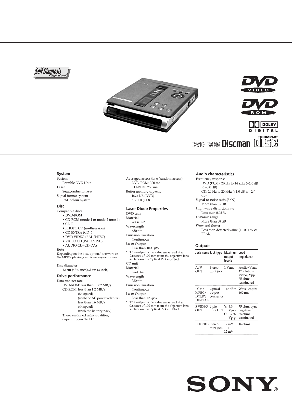
SPECIFICATIONS
AEP Model
UK Model
9-928-104-31
— Continued on next page —
PORTABLE DVD-ROM DRIVE
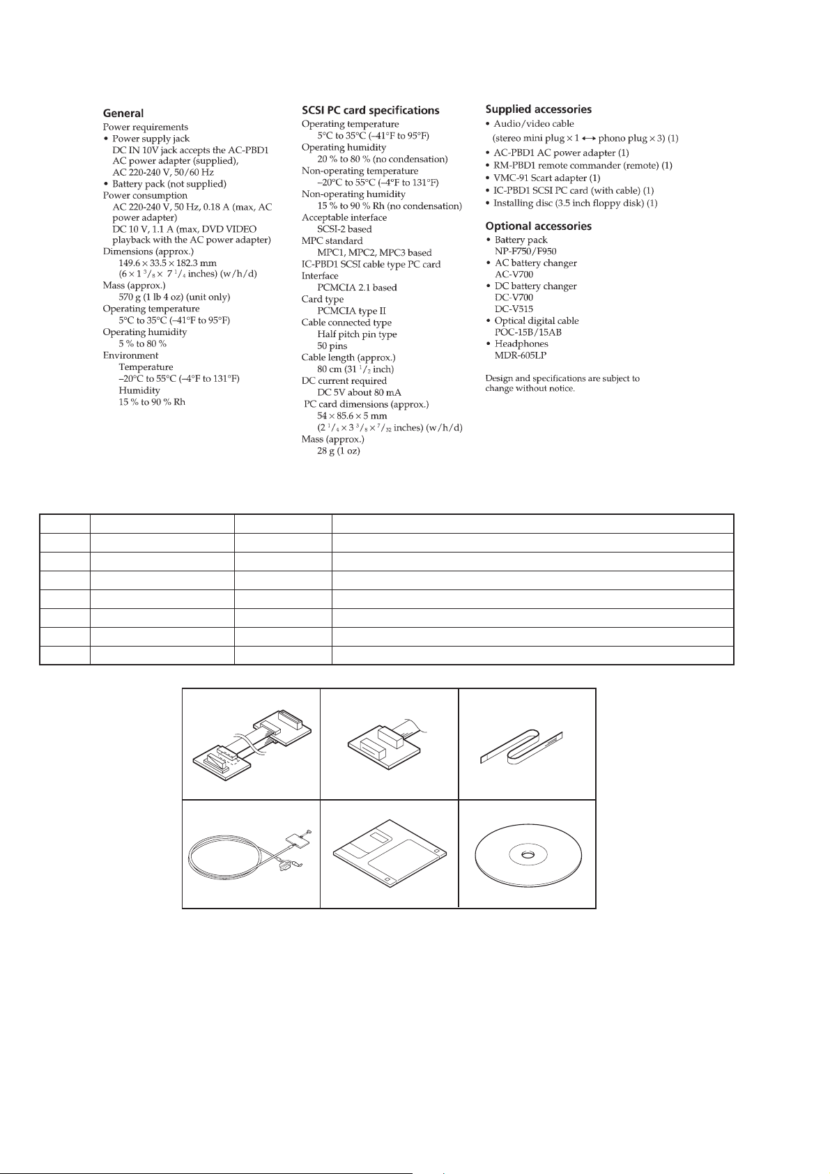
Service T ool List
Ref.No. Name Part Code Usage
1 Extension cable 1 J-2500-129-1 Extension cable between the MAIN board CN453 and the SUB board CN454
2 Extension cable 2 J-2500-130-1 Extension cable between the MAIN board CN651 and the MD sled motor
3 FFC Extension cable J-2500-131-1 Extension cable between the MAIN board CN652 and the MD spindle motor
4 Serial Extension cable J-2500-132-1 RS-232C cable between the MAIN board CN802 PC (with conversion board)
5 Rewriting froppy disc J-2500-133-1 Rewriting software
6 Test Disc (ROM) 8-797-401-80 The CPC ROM is also used here.
7 Test Disc (ROM) 8-797-402-00 The CPC ROM is also used here.
1
23
456, 7
SAFETY-RELATED COMPONENT WARNING!!
COMPONENTS IDENTIFIED BY MARK ! OR DO TTED LINE WITH
MARK ! ON THE SCHEMATIC DIAGRAMS AND IN THE PARTS
LIST ARE CRITICAL TO SAFE OPERATION. REPLACE THESE
COMPONENTS WITH SONY PARTS WHOSE PART NUMBERS
APPEAR AS SHOWN IN THIS MANUAL OR IN SUPPLEMENTS
PUBLISHED BY SONY.
— 2 —

TABLE OF CONTENTS
SERVICE NOTE ·························································· 4
1. GENERAL ·································································· 1-1
2. DISASSEMBLY
2-1. SUB BOARD ································································· 2-1
2-2. DVD MECHANISM (DVDM-D50), MAIN BOARD ··2-1
2-3. UPPER LID ASSEMBLY ·············································· 2-2
2-4. OCONTROL FLEXIBLE BOARD ······························· 2-2
3. BLOCK DIAGRAMS
3-1. OVERALL BLOCK DIAGRAM ··································· 3-1
3-2. RF SERVO BLOCK DIAGRAM··································· 3-3
3-3. SCSI INTERFACE BLOCK DIAGRAM ······················ 3-5
3-4. VIDEO/AUDIO BLOCK DIAGRAM ··························· 3-7
3-5. SYSTEM CONTROL BLOCK DIAGRAM·················· 3-9
3-6. POWER BLOCK DIAGRAM ····································· 3-11
4. PRINTED WIRING BOARDS AND SCHEMATIC
DIAGRAMS
• MAIN PRINTED WIRING BOARD·························· 4-1
• MAIN (RF) SCHEMATIC DIAGRAM ······················ 4-5
• MAIN (DECODER) SCHEMATIC DIAGRAM ········ 4-8
• MAIN (CD DSP) SCHEMATIC DIAGRAM ··········· 4-11
• MAIN (SYSTEM CONTROL)
SCHEMATIC DIAGRAM ········································ 4-15
• MAIN (DVD DSP) SCHEMATIC DIAGRAM ········ 4-19
• MAIN (SCSI) SCHEMATIC DIAGRAM················· 4-21
• MAIN (MOTOR DRIVER)
SCHEMATIC DIAGRAM ········································ 4-23
• MAIN (AV CONTROL)
SCHEMATIC DIAGRAM ········································ 4-26
• MAIN (CONNECTOR)
SCHEMATIC DIAGRAM ········································ 4-29
• MAIN (POWER SUPPLY)
SCHEMATIC DIAGRAM ········································ 4-31
• REMOTE PRINTED WIRING BOARD ·················· 4-33
• REMOTE SCHEMATIC DIAGRAM ······················· 4-34
• SUB PRINTED WIRING BOARD··························· 4-35
• SUB (MPEG DECODER)
SCHEMATIC DIAGRAM ········································ 4-37
• SUB (VIDEO D/A CONVERTER)
SCHEMATIC DIAGRAM ········································ 4-40
• SUB (CONNECTOR) SCHEMATIC DIAGRAM ···· 4-43
5. IC PIN FUNCTION DESCRIPTION
5-1. SYSTEM CONTROL MICON
(MAIN BOARD IC801)················································· 5-1
5-2. A/V CONTROL MICON (MAIN BOARD IC901)······· 5-3
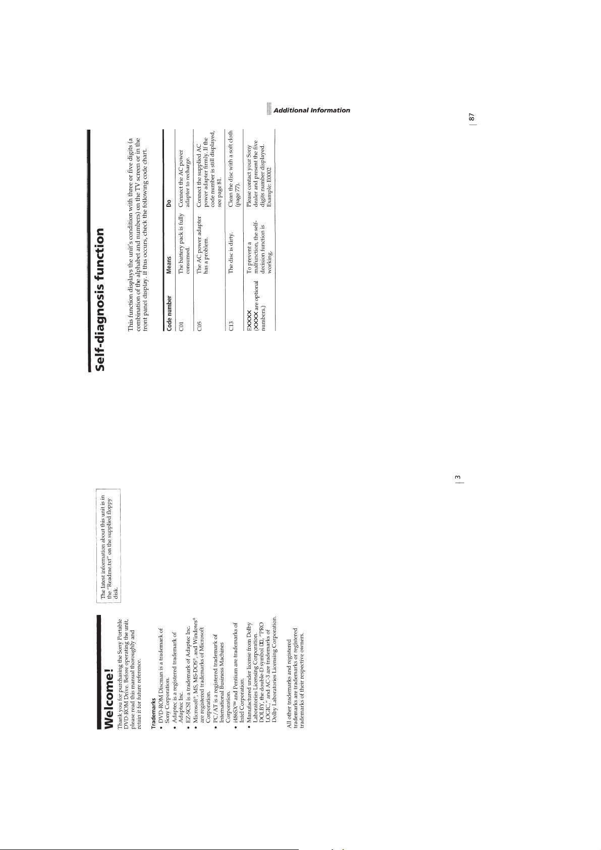
6. SELF DIAGNOSIS FUNCTION ·························· 6-1
7. ELECTRICAL ADJUSTMENT
7-1. CHARGE VOLTAGE ADJUSTMENT ························· 7-1
7-2. VIDEO ADJUSTMENT················································· 7-1
8. REPAIR PARTS LIST
8-1. EXPLODED VIEWS
8-1-1.LOWER CABINET SECTION······································8-1
8-1-2.UPPER CABINET SECTION ······································· 8-2
8-2. ELECTRICAL PARTS LIST ········································· 8-3
— 3 —
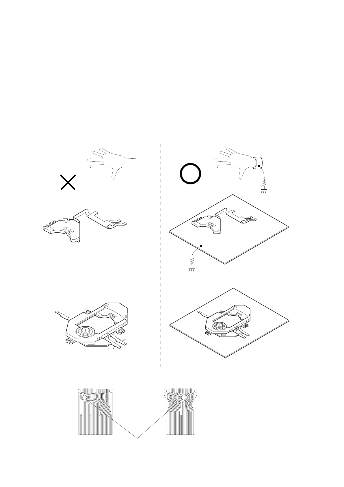
SERVICE NOTE
Do not unpack or install or repair the optical pickup unit KHS-190A series without the grounding
processing as shown below.
1. Grounding the human body
Be sure to wear a grounding wrist strap (10 Ω or less) around your wrist to ground the static electricity accumulated in human body.
2. Grounding the work bend
Place a conductive sheet (10 Ω or less) or a copper plate on the work bench on which the merchandise to be repaired is placed. (The black
sheet that is used for packaging the optical pickup unit, is a conductive sheet.) Connect the conductive sheet or the copper plate to an
electrical ground.
3. Be careful that your clothes do not touch the optical pickup unit because the static electricity accumulated in your clothes are not
grounded through the grounding wrist strap.
4. When the optical pickup unit is shipped from the factory, the laser diode pins are shorted to protect the laser diode from static electricity.
To open the shorting, connect the laser diode to an appropriate APC (Automatic laser Power Control) circuit first, then remove the
soldering quickly with a soldering iron having the insulation resistance of 1M or more.
Optical pickup unit (KHS-190A/J1N)
Optical pickup unit
DVD mechanism (DVDM-D50)
1 Grounding wrist strap
1MΩ
1MΩ
Flexible board
2 Conductive sheet or copper plate
B
A
AB
[Caution]
After installing the optical pickup unit, remove soldering.
— 4 —
SECTION 1
GENERAL
PBD-D50
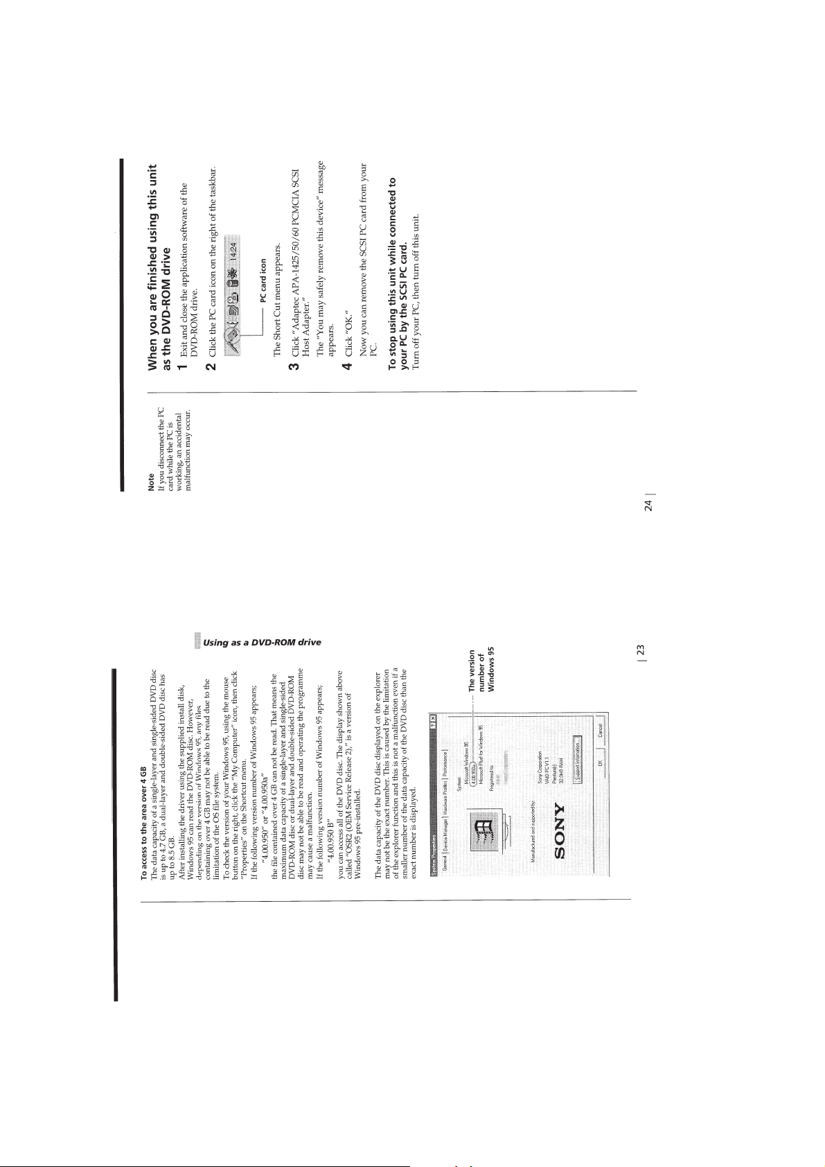
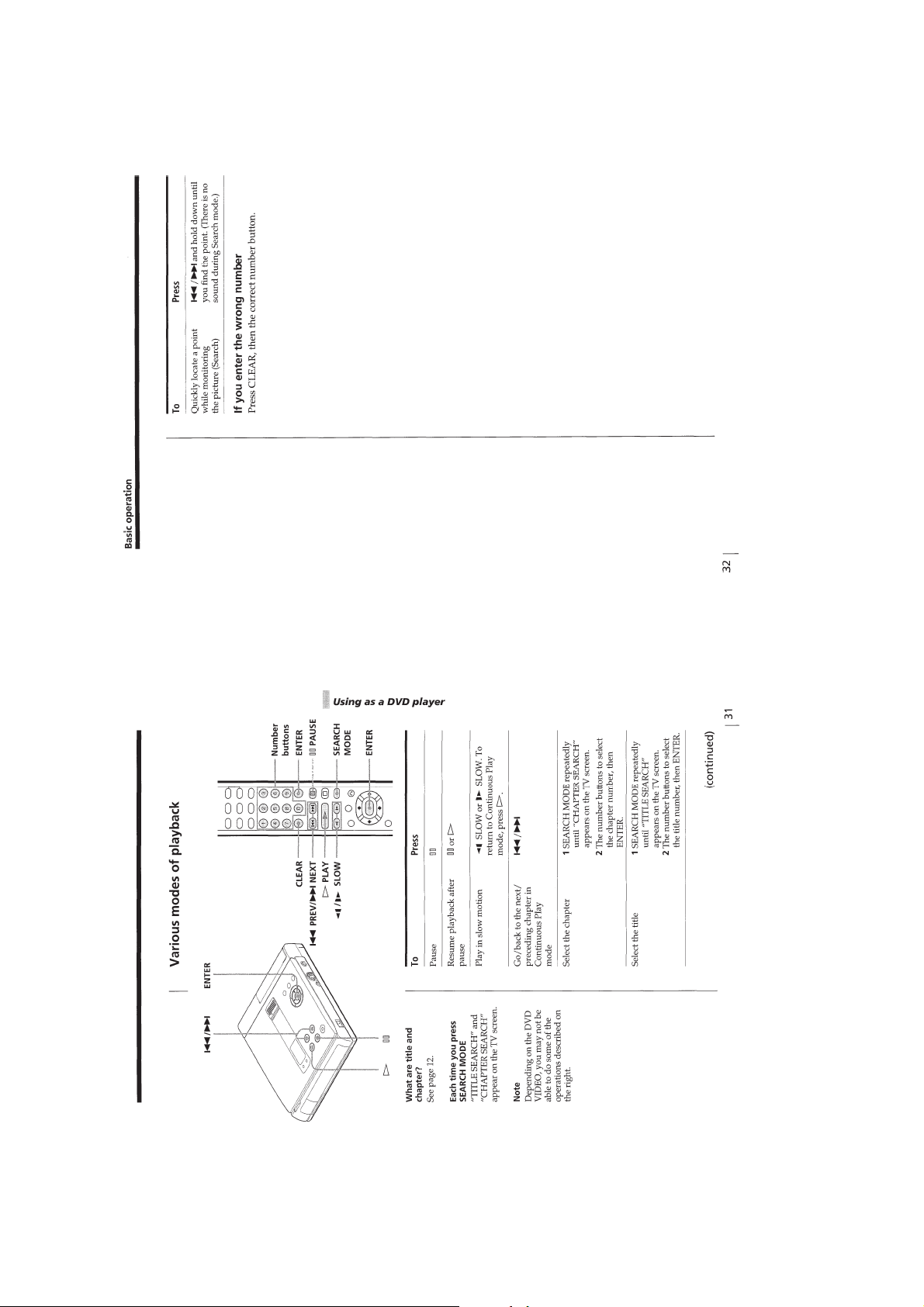
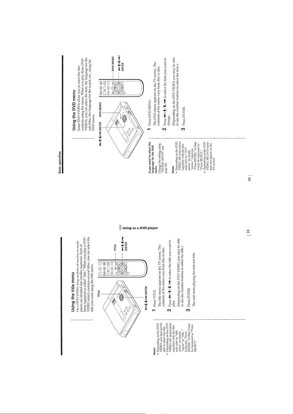
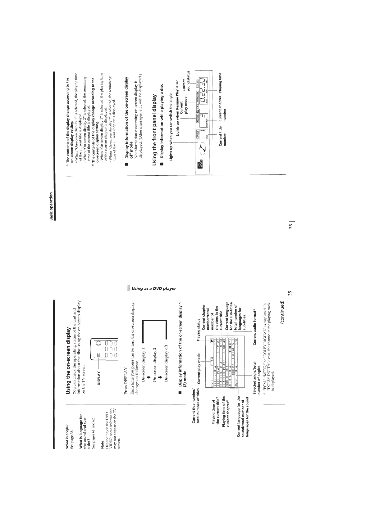
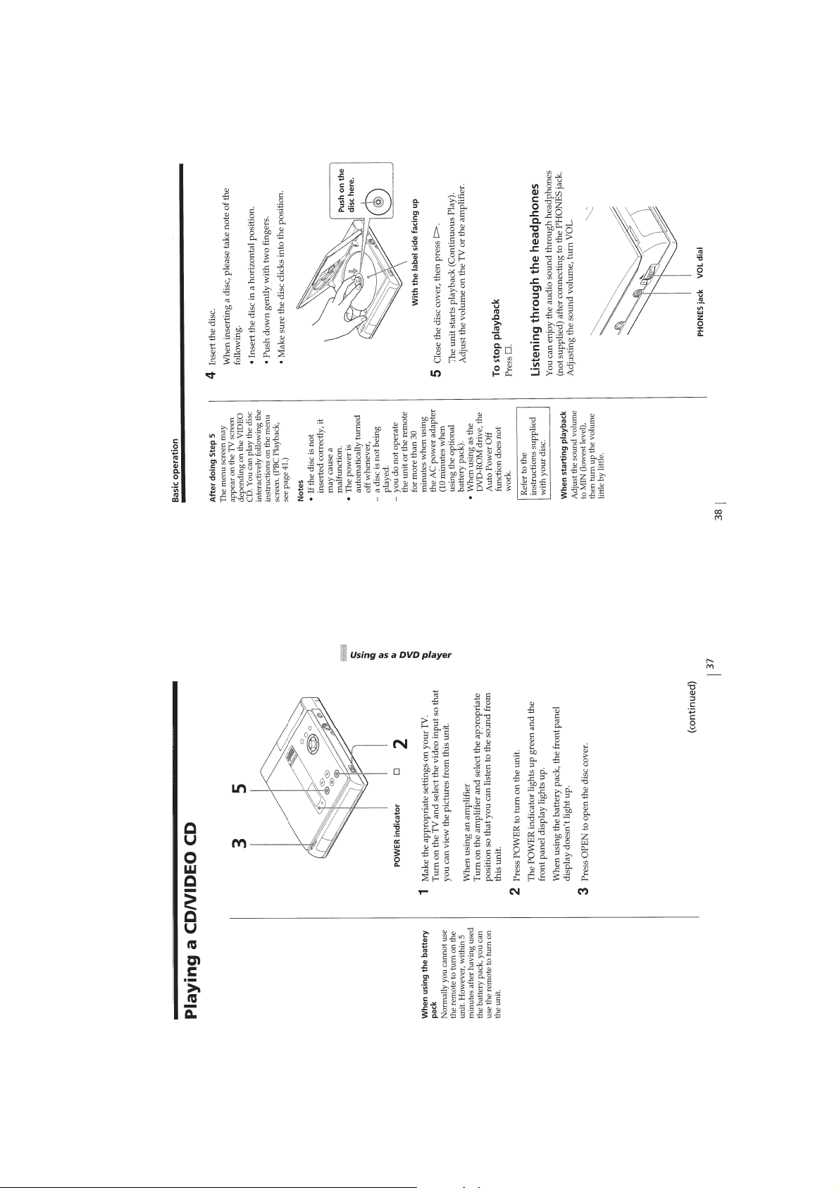
This section is extracted from
instruction manual.3-862-692-21
1-1
1-2
1-3
1-4
1-5
1-6
1-7
1-8
1-9
1-10
1-11
1-12
1-13
1-14
1-15
1-16
1-17
1-18
1-19
1-20
1-21
1-22
1-23
1-24

1-25
1-26
 Loading...