

Sony NWE-403, NWE-407, NWE-405 Service manual
NW-E403/E405/E407
SERVICE MANUAL
Ver. 1.5 2005.10
US and foreign patents licensed from
Dolby Laboratories.
SPECIFICATIONS
Maximum recording time (Approx.)
NW-E403
ATRAC3
4 hr. 10 min. (132 kbps)
5 hr. 20 min. (105 kbps)
8 hr. 30 min. (66 kbps)
MP3
2 hr. 10 min. (256 kbps)
4 hr. 20 min. (128 kbps)
NW-E405
ATRAC3
8 hr. 30 min. (132 kbps)
10 hr. 40 min. (105 kbps)
17 hr. 00 min. (66 kbps)
MP3
4 hr. 20 min. (256 kbps)
8 hr. 50 min. (128 kbps)
NW-E407
ATRAC3
17 hr. 00 min. (132 kbps)
21 hr. 40 min. (105 kbps)
34 hr. 10 min. (66 kbps)
MP3
8 hr. 50 min. (256 kbps)
17 hr. 40 min. (128 kbps)
ATRAC3plus
2 hr. 10 min. (256 kbps)
8 hr. 40 min. (64 kbps)
11 hr. 40 min. (48 kbps)
ATRAC3plus
4 hr. 20 min. (256 kbps)
17 hr. 30 min. (64 kbps)
23 hr. 30 min. (48 kbps)
ATRAC3plus
8 hr. 50 min. (256 kbps)
35 hr. 00 min. (64 kbps)
47 hr. 00 min. (48 kbps)
Audio compression technology
Adaptive Transform Acoustic Coding3 (ATRAC3)
Adaptive Transform Acoustic Coding3plus
(ATRAC3plus)
MPEG1 Audio Layer-3 (MP3): 32 to 320 kbps,
variable bit rate-compliant
Frequency response
20 to 20,000 Hz (single signal measurement)
Interface
Headphone: Stereo mini
USB
Signal-to-noise ratio (S/N)
80 dB or more (excluding ATRAC3 66 kbps)
Dynamic range
85 dB or more (excluding ATRAC3 66 kbps)
Operating temperature
5˚C to 35˚C (67˚F to 95˚F)
Power source
•Built-in rechargeable lithium-ion battery
• USB power (from a computer through supplied
USB cable)
Battery life (continuous
playback)*
ATRAC3 format: Approximately 50 hours
(Playback at 105 kbps)
US Model
NW-E405/E407
Canadian Model
AEP Model
Korean Model
NW-E403/E405/E407
Australian Model
Tourist Model
NW-E405/E407
ATRAC3plus format: Approximately 45 hours
(Playback at 48 kbps)
MP3 format: Approximately 40 hours
(Playback at 128 kbps)
*This is when the power save setting is normal.
The battery duration will vary depending on
temperature and usage.
Dimension
84.9
×
28.8
×
13.9
mm (
1.7
3 3/
oz)
(w/h/d, projecting parts not included)
Mass
Approx. 47 g (
Supplied accessories
Headphones (1)
Dedicated USB cable (1)
Extension headphone cord (NW-E407 only) (1)
Carrying pouch (NW-E407 only) (1)
Clip (1)
CD-ROM for the SonicStage software, PDF file
Operating Instructions, and PDF file SonicStage
Operating Instructions (1)
Quick Start Guide
Design and specifications are subject to
change without notice.
Microsoft, Windows and Windows Media are
trademarks or registered trademarks of Microsoft
Corporation in the United States and/or other
countries.
9
×
1 3/
×
/
8
inches)
16
16
Sampling frequency
ATRAC3, ATRAC3plus, MP3: 44.1 kHz
9-879-600-06
2005J16-1
© 2005.10
Sony Corporation
Connect Company
Published by Sony Engineering Corporation
PORTABLE IC AUDIO PLAYER

NW-E403/E405/E407
TABLE OF CONTENTS
1. GENERAL ................................................................... 3
2. DISASSEMBLY
2-1. Disassembly Flow ........................................................... 5
2-2. Lid (Connector) ............................................................... 6
2-3. Cabinet (Inner) ................................................................ 6
2-4. Arm (Shuttle) ................................................................... 7
2-5. Knob (Shuttle) ................................................................. 8
2-6. MAIN Board.................................................................... 9
2-7. Organic EL Indicator Module ......................................... 10
3. TEST MODE ............................................................... 11
4. DIAGRAMS
4-1. Block Diagram ................................................................ 13
4-2. Printed Wiring Board – MAIN Board (Side A) –........... 14
4-3. Printed Wiring Board – MAIN Board (Side B) –........... 15
4-4. Schematic Diagram – SW Board, MAIN Board (1/5) – 16
4-5. Schematic Diagram – MAIN Board (2/5) – ................... 17
4-6. Schematic Diagram – MAIN Board (3/5) – ................... 18
4-7. Schematic Diagram – MAIN Board (4/5) – ................... 19
4-8. Schematic Diagram – MAIN Board (5/5) – ................... 20
4-9. Printed Wiring Board – SW Board –.............................. 21
5. EXPLODED VIEWS
5-1. Overall-1 .......................................................................... 24
5-2. Overall-2 .......................................................................... 25
6. ELECTRICAL PARTS LIST .................................. 26
Flexible Circuit Board Repairing
• Keep the temperature of the soldering iron around 270 °C
during repairing.
• Do not touch the soldering iron on the same conductor of the
circuit board (within 3 times).
• Be careful not to apply force on the conductor when soldering
or unsoldering.
Notes on chip component replacement
• Never reuse a disconnected chip component.
• Notice that the minus side of a tantalum capacitor may be
damaged by heat.
Microsoft, Windows and Windows Media are trademarks or
registered trademarks of Microsoft Corporation in the United States
and/or other countries.
US and foreign patents licensed from Dolby Laboratories.
All other trademarks and registered trademarks are trademarks or
registered trademarks of their respective holders.
UNLEADED SOLDER
Boards requiring use of unleaded solder are printed with the leadfree mark (LF) indicating the solder contains no lead.
(Caution: Some printed circuit boards may not come printed with
the lead free mark due to their particular size)
: LEAD FREE MARK
Unleaded solder has the following characteristics.
• Unleaded solder melts at a temperature about 40 °C higher
than ordinary solder.
Ordinary soldering irons can be used but the iron tip has to be
applied to the solder joint for a slightly longer time.
Soldering irons using a temperature regulator should be set to
about 350 °C.
Caution: The printed pattern (copper foil) may peel away if
the heated tip is applied for too long, so be careful!
• Strong viscosity
Unleaded solder is more viscou-s (sticky, less prone to flow)
than ordinary solder so use caution not to let solder bridges
occur such as on IC pins, etc.
• Usable with ordinary solder
It is best to use only unleaded solder but unleaded solder may
also be added to ordinary solder.
\
2
SECTION 1
GENERAL
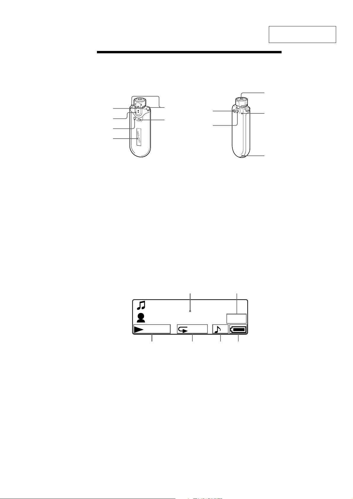
Locating controls
For details about each part, refer to the pages in parentheses.
Rear sideFront side
NW-E403/E405/E407
This section is extracted
from instruction manual.
9
1
2
5
6
3
4
1 Shuttle switch
(pages 17 to 22, 25, 27 to 39)
2 Nx button
(pages 14 to 25, 27 to 29, 31 to 39)
3 SEARCH/MENU button
(pages 15, 17 to 25, 27 to 29, 31 to 39)
4 Display (pages 10, 15, 22, 26)
For details on the display and icons,
refer to page 10.
5 VOL (Volume) +/– button (pages 14,
33)
6 DISPLAY button (pages 26 to 27)
Display
7
8
7 REPEAT/SOUND button
(pages 22 to 24, 28)
8 Strap hole
9 Headphone jack (page 14)
q; Reset button (page 42)
qa USB jack (page 12)
0
qa
Track 1
Artist
01:23
3546
1
Text/graphic information display (pages
15, 22)
Displays album title, artist name, track
number, track name, current date and
time (pages 26 to 28, 31), MESSAGE
(page 46) and menu.
Press the DISPLAY button to switch the
display mode (pages 26 to 28). Switch
the display to Power Save or Display
OFF mode when you do not operate the
unit for a while (page 35).
2 Current track number/total track number
of the Play Range
The track number currently selected or
being played back and the total track
number of the current Play Range is
displayed.
12
1/32
SHUF
3 Playing status indicator
Display current playback mode (N:
playback, x: stop) and elapsed time.
4 Repeat mode indication (page 22)
The current repeat mode icon is
displayed.
5 Digital sound preset indication
(pages 28 to 29)
The current digital sound preset is
displayed if set.
6 Remaining battery indication (pages 12
to 13)
The remaining battery power is
displayed.
2
3
NW-E403/E405/E407
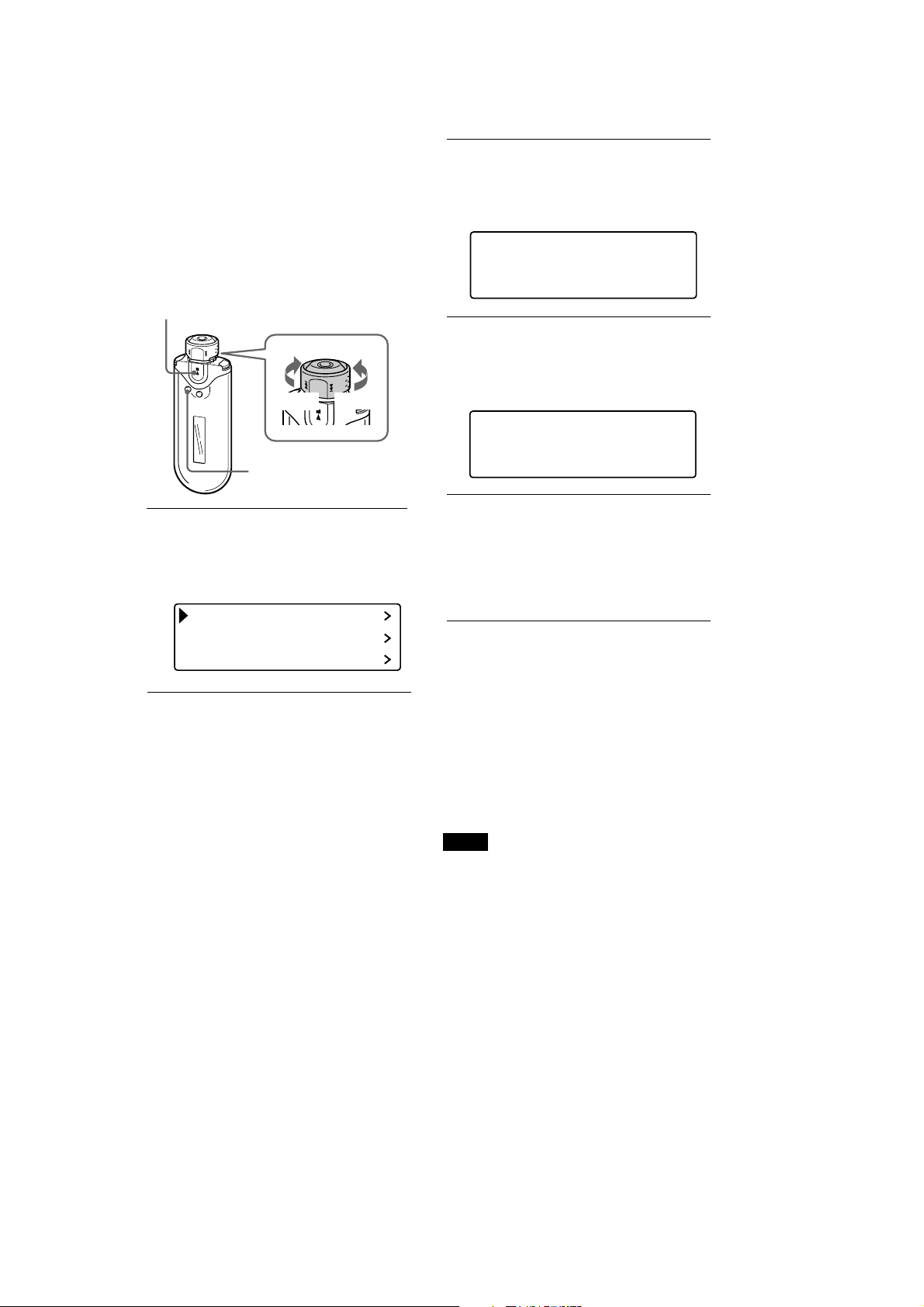
Adjusting the
current time
setting
(Date-Time)
You can set and display the current time.
Nx button
Shuttle switch
to >
SEARCH/
MENU button
1
Press and hold the SEARCH/
MENU button for half a second in
stop mode.
The menu screen is displayed.
Repeat Mode
Sound
Volume Mode
to .
2
Rotate the Shuttle switch to select
“Date-Time>” and press the Nx
button to confirm.
The year digit is displayed in [ ].
Y
MDhm
[2005] 01 / 01 15 : 00
3
Rotate the Shuttle switch to adjust
the “year” setting and press the
Nx button to confirm.
The month digit is displayed in [ ].
Y
MDhm
2005 [01]/ 01 15 : 00
4
As you did in step 3, adjust the
settings for “month”, “date”,
“hour”, and “minute”.
After rotating the Shuttle switch to
adjust the time and date setting, pressing
the Nx button to confirm.
To cancel the Menu mode
Press the SEARCH/MENU button to return the
screen to the previous stage. Press repeatedly to exit
menu mode.
To display the current time
Press the DISPLAY button repeatedly until the
“Clock” is displayed (page 26).
Note, however, when the “Clock” is set to off in the
Display Screen menu (page 27), you cannot display
the current time by the procedure above.
Notes
• If the unit is not used for a long time, your
settings for date and time may need to be reset.
• If the current time is not set, the display for the
date and time will show “--”.
4
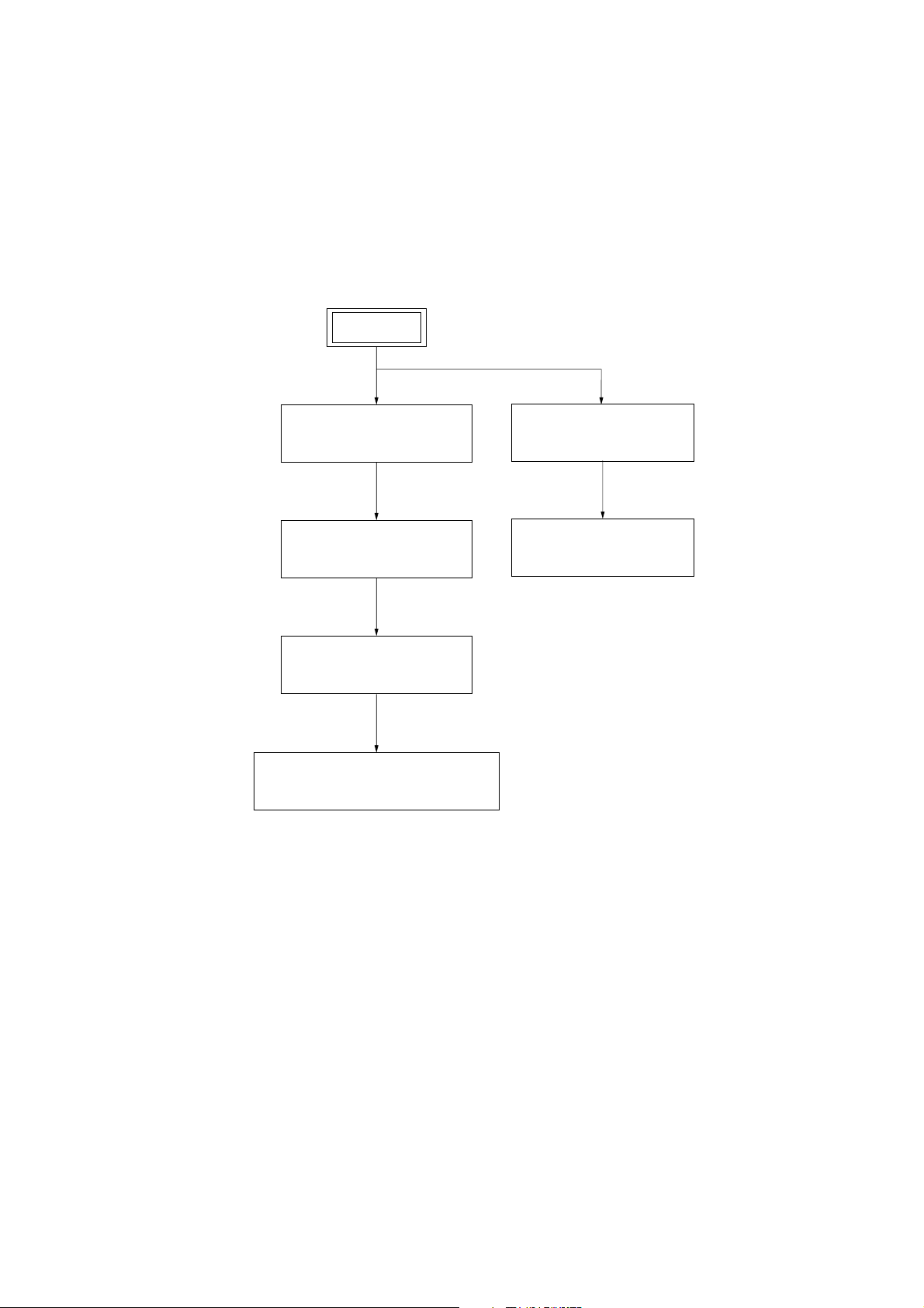
SECTION 2
DISASSEMBLY
Note: Follow the disassembly procedure in the numerical order given.
2-1. DISASSEMBLY FLOW
SET
NW-E403/E405/E407
2-2. LID (CONNECTOR)
(Page 6)
2-3. CABINET (INNER)
(Page 6)
2-6. MAIN BOARD
(Page 9)
2-7. ORGANIC EL INDICATOR MODULE
(Page 10)
2-4. ARM (SHUTTLE)
(Page 7)
2-5. KNOB (SHUTTLE)
(Page 8)
5
NW-E403/E405/E407
Note: Follow the disassembly procedure in the numerical order given.
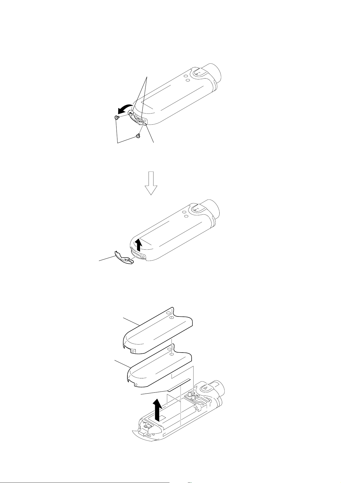
2-2. LID (CONNECTOR)
1
3
two tapping screws 1.4
two claws
2
Open the lid (connector) in the
direction of the arrow.
4
Lid (Connector)
2-3. CABINET (INNER)
1
2
cabinet (top)
3
cabinet (inner)
two
adhesive sheets (cabinet)
6
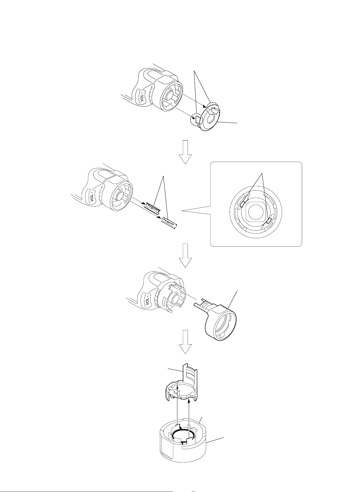
2-4. ARM (SHUTTLE)
3
two
1
two claws
springs (slide)
2
cover (jack)
two
NW-E403/E405/E407
springs (slide)
6
arm (shuttle)
Printed side
4
knob (shuttle), arm (shuttle),
spring (shuttle)
5
knob (shuttle),
spring (shuttle)
7
NW-E403/E405/E407
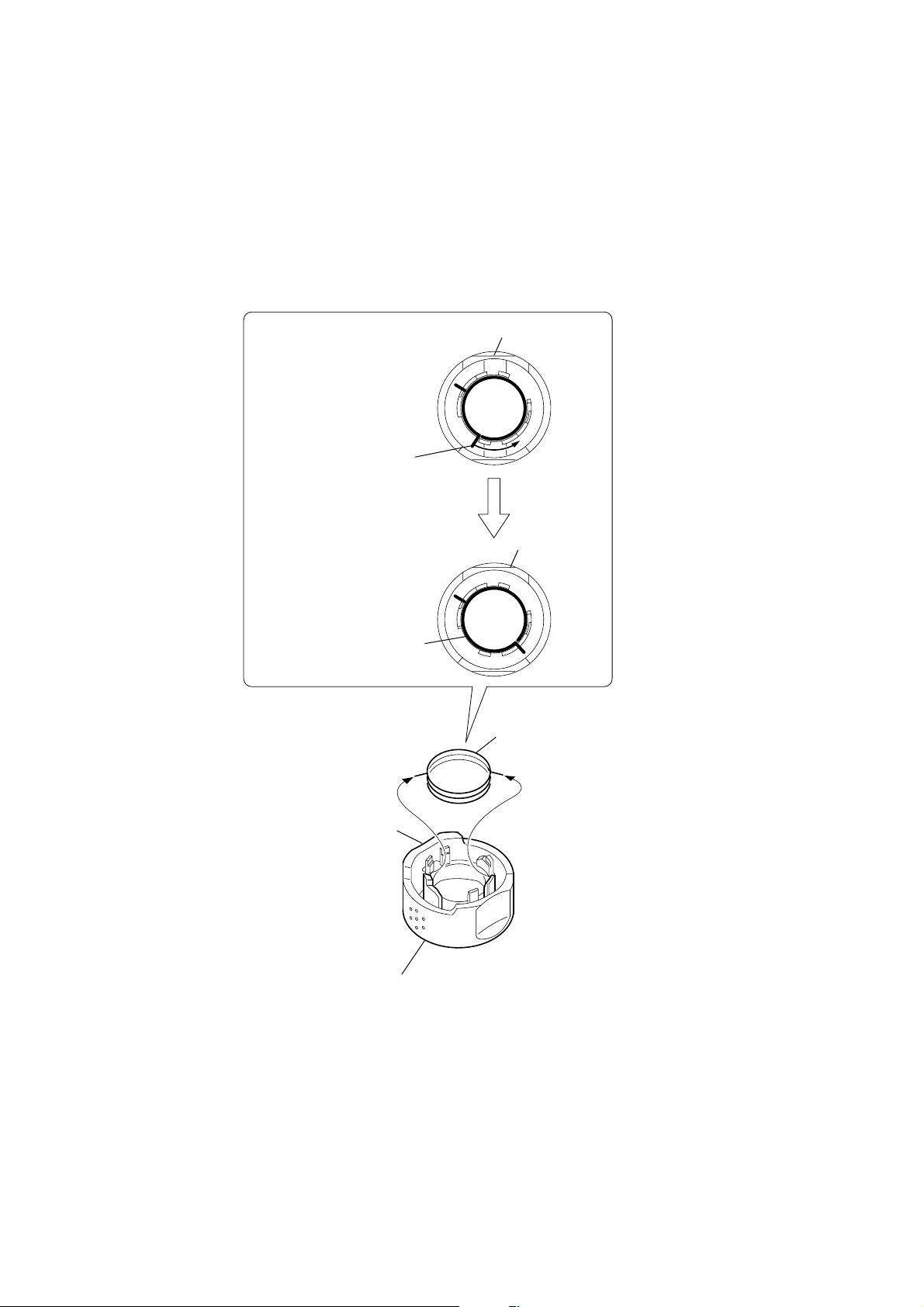
2-5. KNOB (SHUTTLE)
How to install the spring
1
Tentatively install the
spring (shuttle), and
move in the direction
of the arrow.
2
spring (shuttle)
Printed side
Printed side
1
spring (shuttle)
Printed side
2
knob (shuttle)
8
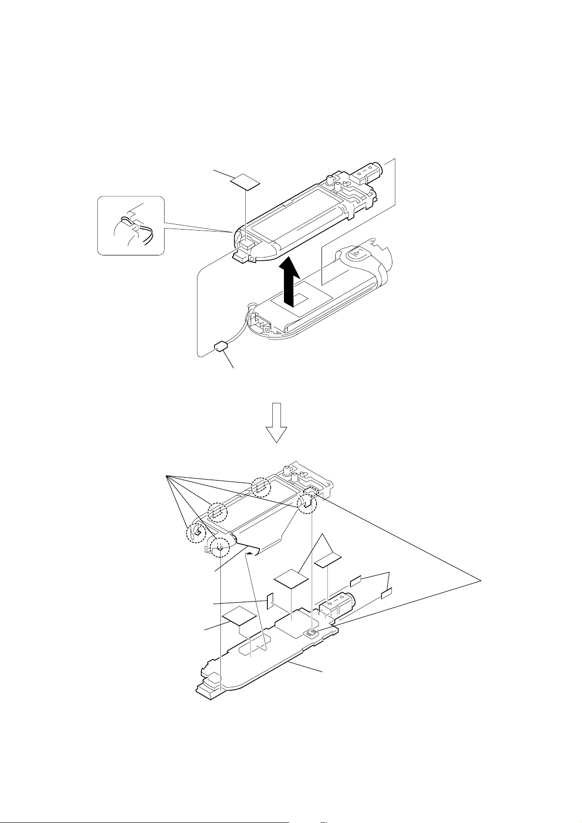
2-6. MAIN BOARD
r
1
sheet (connector)
NW-E403/E405/E407
3
five claws
5
organic EL indicator
module connector
6
(PWB)
9
sheet
(shield)
spacer
2
connector
8
spacer
(VOL)
4
connecto
0
MAIN board
9
 Loading...