

Sony MZE-909 Service manual
MZ-E909
SERVICE MANUAL
Ver 1.3 2002.06
with SUPPLEMENT-1
US and foreign patents licensed from Dolby
Laboratories Licensing Corporation
SPECIFICATIONS
Audio playing system
MiniDisc digital audio system
Laser diode properties
Material: GaAlAs
Wavelength: λ = 790 nm
Emission duration: continuous
Laser output: less than 44.6 µW*
* This output is the value measured at a distance
of 200 mm from the objective lens surface on
the optical pick-up block with 7 mm aperture.
Revolutions
Approx. 300 rpm to 2,700 rpm
Error correction
ACIRC (Advanced Cross Interleave Reed Solomon Code)
Sampling frequency
44.1 kHz
Coding
ATRAC (Adaptive TRansform Acoustic Coding)
ATRAC3: LP2
ATRAC3: LP4
Modulation system
EFM (Eight to Fourteen Modulation)
Number of channels
2 stereo channels
1 monaural channel
Frequency response
20 to 20,000 Hz ± 3 dB
Wow and Flutter
Below measurable limits
Outputs
Headphones/earphones: stereo mini-jack,
maximum output level
5 mW + 5 mW (US model) load impedance
16 ohms,
3 mW + 3 mW (Other models)
load impedance 32 ohms
US Model
AEP Model
E Model
Tourist Model
Model Name Using Similar Mechanism NEW
MD Mechanism Type MT-MZE909-173
Optical Pick-up Mechanism Type LCX-4E
Power requirements
Nickel metal hydride rechargeable battery
One NH-14WM(A) (supplied): 1.2V, 1,350 mAh
One LR6 (size AA) battery (not supplied)
External power jack (for the rechargeable
battery): Power rating 3V DC
Battery life
Batteries SP Stereo LP2 LP4
Ni-MH 38 45 53
rechargeable
battery
NH-14WM(A)3)
LR6 (SG) 60 70 83
Sony Alkaline
dry battery 4)
LR6 (SG)4) and 100 122 145
NH-14WM(A)3)
1)
Measured with the power save function on (see
“Preserving battery power”) is on.
2)
Measured in accordance with the JEITA (Japan
Electronics and Information Technology
Industries Association) standard (using a Sony
MDW-series Mini-disc).
3)
With a fully charged battery
4)
When using a Sony LR6 (SG) “STAMINA” alkaline dry
battery (produced in Japan).
Note
The battery operation may be shorter than that
specified, depending on the operating conditions,
the temperature of the location, and the type of
battery being used.
1)
(Unit: Approx. hours) (JEITA 2) )
(normal) Stereo Stereo
PORTABLE MINIDISC PLAYER
9-873-304-04
2002F0200-1
© 2002.06
Sony Corporation
Personal Audio Company
Published by Sony Engineering Corporation
MZ-E909
Ver 1.1 2001.11
Dimensions
Approx. 71.1 x 77.6 x 12.5 mm (w/h/d) (2 7 / 8 x 3 1 /8 x 1 /2 in.)
(not including projecting parts and controls)
Mass
Approx. 49 g (1.8 oz) (the player only)
Supplied accessories
Headphones/earphones with a remote control
(1)
Battery charging stand (1)
AC power adaptor (for the supplied battery
charging stand)
Rechargeable battery (1)
Rechargeable battery carrying case (1)
Dry battery case (1)
Carrying pouch (1)
AC plug adaptor (1) (world model only)
US and foreign patents licensed from Dolby Laboratories.
Design and specifications are subject to change without notice.
TABLE OF CONTENTS
Specifications ........................................................................... 1
1. SERVICING NOTE...................................................... 3
2. GENERAL
Location and Function of Controls .................................... 4
3. DISASSEMBLY
3-1. “Lid ASSY, Upper”..................................................... 5
3-2. Mechanism Deck ........................................................ 5
3-3. Bracket (R) ASSY ...................................................... 6
3-4. Main Board Sub ASSY, Bracket (L) ASSY,
SW Board ............... 6
3-5. Optical Pick-up ASSY................................................ 7
4. TEST MODE.................................................................. 8
5. ELECTRICAL ADJUSTMENTS........................... 12
6. DIAGRAMS
6-1. Block Diagram.......................................................... 17
6-2. Printed Wiring Boards – Main Section (1/2) –......... 18
6-3. Printed Wiring Boards – Main Section (2/2) –......... 19
6-4. Schematic Diagram – Main Section (1/2) – ............. 20
6-5. Schematic Diagram – Main Section (2/2) – ............. 21
6-6. Printed Wiring Boards – Audio Section – ................ 22
6-7. Schematic Diagram – Audio Section –..................... 23
CAUTION
Use of controls or adjustments or performance of procedures
other than those specified herein may result in hazardous
radiation exposure.
Flexible Circuit Board Repairing
• Keep the temperature of the soldering iron around 270°C during
repairing.
• Do not touch the soldering iron on the same conductor of the
circuit board (within 3 times).
• Be careful not to apply force on the conductor when soldering or
unsoldering.
Notes on chip component replacement
• Never reuse a disconnected chip component.
• Notice that the minus side of a tantalum capacitor may be damaged by heat.
SAFETY-RELATED COMPONENT WARNING!!
COMPONENTS IDENTIFIED BY MARK ! OR DOTTED LINE WITH
MARK !ON THE SCHEMATIC DIAGRAMS AND IN THE PARTS
LIST ARE CRITICAL TO SAFE OPERATION.
REPLACE THESE COMPONENTS WITH SONY PARTS WHOSE
PART NUMBERS APPEAR AS SHOWN IN THIS MANUAL OR IN
SUPPLEMENTS PUBLISHED BY SONY.
* Replacement of CXD2671B-206GA (IC601) used in this set
requires a special tool.
2
7. EXPLODED VIEWS
7-1. Main Section............................................................. 26
7-2. Mechanism Deck Section ......................................... 27
8. ELECTRICAL PARTS LIST................................... 28
r
UNLEADED SOLDER
Boards requiring use of unleaded solder are printed with the
lead-free mark (LF) indicating the solder contains no lead.
(Caution: Some printed circuit boards may not come printed
with the lead free mark due to their particular size.)
: LEAD FREE MARK
Unleaded solder has the following characteristics.
• Unleaded solder melts at a temperature about 40°C higher
than ordinary solder.
Ordinary soldering irons can be used but the iron tip has to
be applied to the solder joint for a slightly longer time.
Soldering irons using a temperature regulator should be set
to about 350°C.
Caution: The printed pattern (copper foil) may peel away if
the heated tip is applied for too long, so be careful!
• Strong viscosity
Unleaded solder is more viscous (sticky, less prone to
flow) than ordinary solder so use caution not to let solder
bridges occur such as on IC pins, etc.
• Usable with ordinary solder
It is best to use only unleaded solder but unleaded solder
may also be added to ordinary solder.
MAIN BOARD SUB ASSY
• Audio board is supplied with main board sub ASSY.
• Audio board can't be moved away from main board.
Give a damage when take it off forcibly.
• The part that audio board overlap with main board can't be re-
paired.
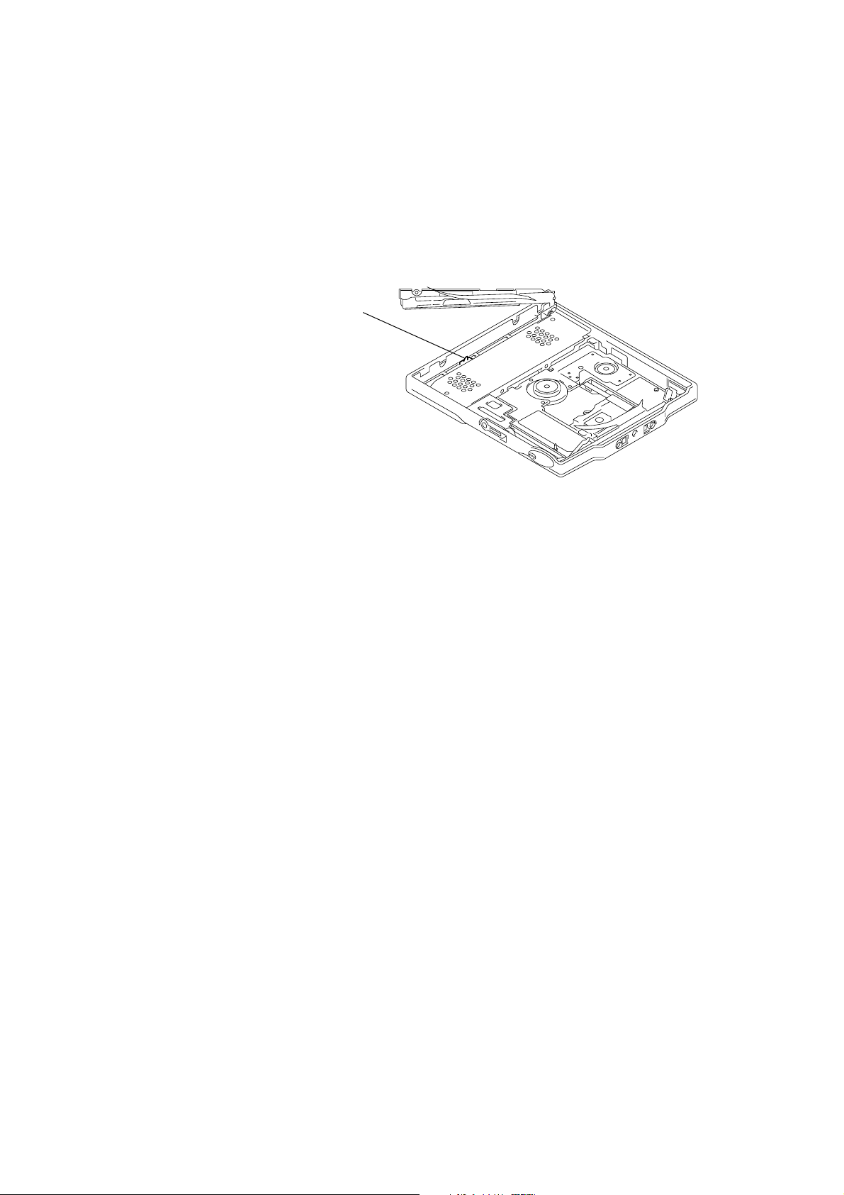
SECTION 1
SERVICING NOTE
When repairing this device with the power on, if you remove the main board, this device stops working.
In this case, you work without the device stopping by fastening the hook of the Open/Close detection switch (S809).
Open/Ciose detection switch (S809)
MZ-E909
3
MZ-E909
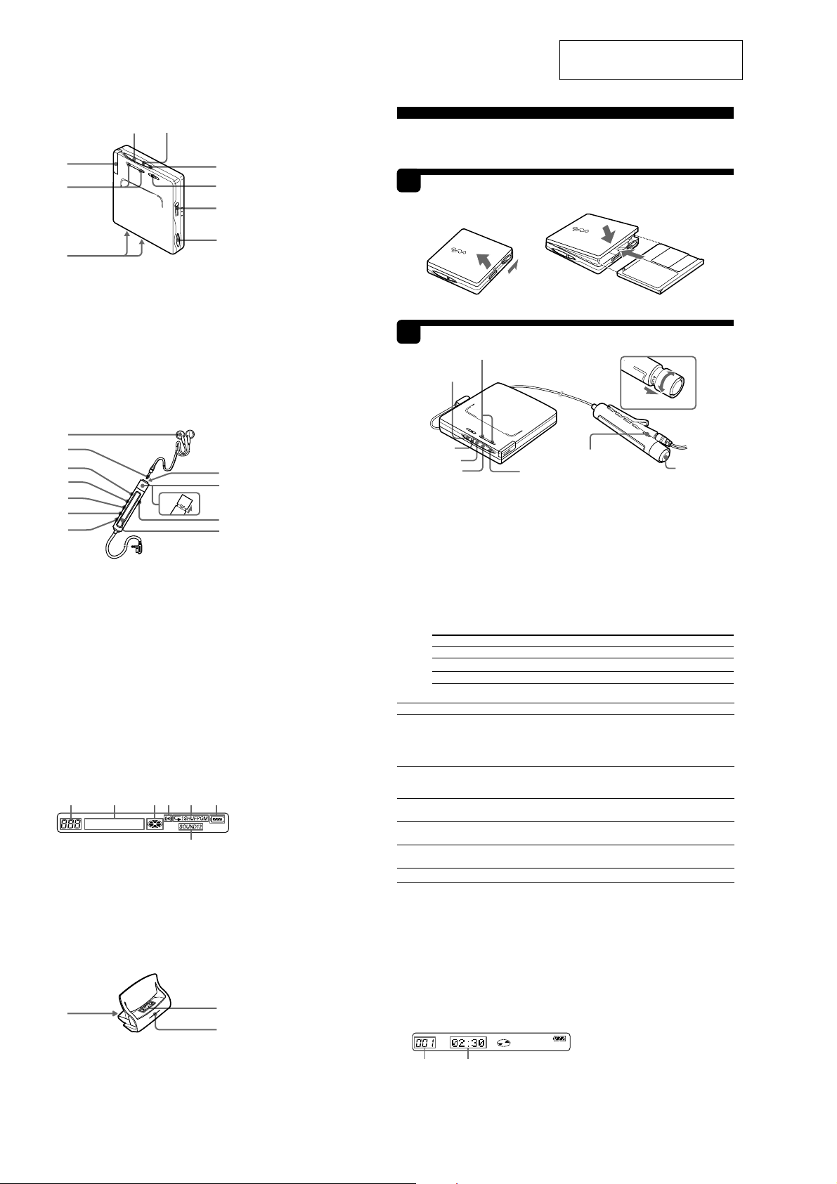
The Player
2
1
9
8
7
1 ./x/
2 3 Color Info-LED
3 GROUP button
4 HOLD (Locking the control) switch
5 i (earphones) jack
6 OPEN switch
7 Terminals for charging stand/
8 VOL +/– button
9 Battery compartment
The earphones with a remote
control
A
B
C
D
E
F
G
1 Headphones/earphones
2 Stereo mini plug
3 X (pause) button
4 SOUND button
5 RPT/ENT (Repeat/Enter) button
6 PLAYMODE button
7 DISPLAY button
8 x (stop) button*
9 Control (./
q; Control VOL +/–
qa HOLD (Locking the control) switch
qs Display window
* The stop button also operates as the enter
button, depending on the function.
The display window of the remote
control
ABCDE
1 Track number display
2 Charactor information display
3 Disc indication
4 Alarm indication
5 Play mode indication
6 Battery level indication
7 SOUND indication
The battery charging stand
C
1 Terminals for charging
2 CHARGE lamp
3 DC IN (3V jack) (at the rear)
N>
button
dry battery case (at the bottom)
J
+
–
N>
)
Pull and turn to adjust the volume.
G
F
C
D
E
F
A
B
H
I
K
L
SECTION 2
GENERAL
Playing an MD
1
1
2
3 Color Info-LED
> N
To
Find the beginning of
the current track or
the previous track
Find the beginning
of the next track
Go backwards
while playing
Go forward
while playing
Pause
Remove the MD
2)
You can turn off the beep sound. For more details, see “Turning off the beep sound.”
3)
If you turn the control towards . on the remote control (or press . on the player) during the
first track of the disc, the player goes to the beginning of the last track on the disc.
4)
If you turn the control towards N> on the remote control (or press > N on the player) during
the last track of the disc, the player goes to the beginning of the first track on the disc.
5)
If you open the lid, the playback will begin from the beginning of the first track (except when disc
information is stored to the personal disc memory or when group mode is on).
z
The MZ-E909 supports the newly developed DSP TYPE-R for ATRAC.
It thus allows you to enjoy TYPE-R high-quality sound from MDs recorded in SP stereo on TYPE-Requipped MD decks, etc.
Note
When removing the disc, make sure to press x first, and then slide OPEN.
Viewing the display window of the remote control
Track number Track name6) or elapsed time of the track
6)
Appears only with MDs that have been electronically labeled.
z
• The player can play the track recorded by 2 × or 4 × long playing mode (LP2 or LP4). Normal stereo
playback, LP2 stereo playback, LP4 stereo playback or monaural playback is automatically selected to
match the audio source.
• The display on the remote control will turn off shortly after you press x.
This section is extracted from
instruction manual.
Insert an MD.
Slide OPEN to open the lid.
1
2
Insert an MD.
3
Insert an MD with the label side facing up, pushing the
MD to the direction of the arrow in the illustration.
2
3
Close the lid.
Play an MD.
VOLUME +/–
GROUP
1)
x
1
Turn the control towards N> on the remote control (or press > N
on the player) to play the disc.
A short beep sounds in the headphones/earphones when using the remote control.
The LED flashes and then lights up.
2
Pull and turn VOL +/– on the remote control (or press VOLUME +/– on the
player) to adjust the volume.
The volume indicator appears in the display, allowing you to check the
volume level. After you adjust the volume, push back the control.
To stop play, press x.
Playback starts from the point you last stopped playing. To start playback from the
beginning of the disc, turn and hold the control towards N> on the remote control
(or hold down
1)
The LED indicates the current operating status by the lighting up in the following colors.
When the battery power is exhausted, the LED starts flashing. For more details, see
“When to replace or recharge the battery.”
LED color Operating status
Red Normal play (The LED lights up continuously)
Green Group mode* (The LED lights up continuously)
Orange Group skip mode* (The LED lights for about 5 seconds)
*For more details, see “Using the group function.”
3)
4)
.
> N
on the player) for 2 seconds or more.
Do this (Beeps2) in the headphones)
Turn the control towards . on the remote control once
(three short beeps). (Or press . on the player once.)
Turn the control towards . on the remote control repeatedly
(continuous three short beeps). (Or press . on the player
repeatedly.)
Turn the control towards N> on the remote control (two
short beeps).
Press > N on the player once.
Turn and hold the control towards . on the remote control.
Hold down . on the player.
Turn and hold the control towards N> on the remote control.
Hold down > N on the player.
Press X on the remote control (continuous short beeps).
Press X on the remote control again to resume play.
Press x, and then slide OPEN.
2
VOL+
VOL–
1N>
X
.
5)
x
4
SECTION 3
k
DISASSEMBLY
r
The equipment can be removed using the following procedure.
Set
Note : Follow the disassembly procedure in the numerical order given.
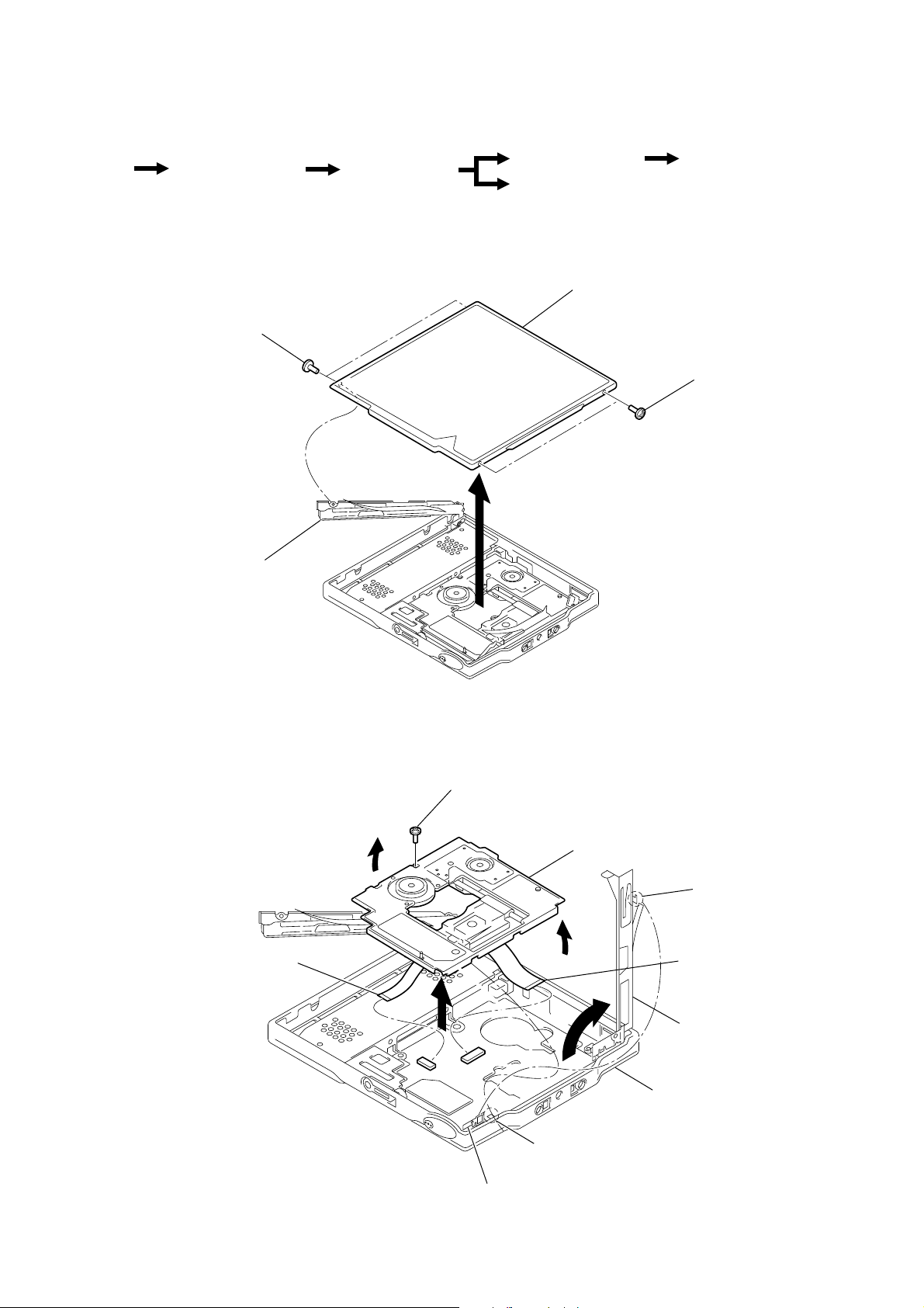
3-1. “LID ASSY, UPPER”
“Lid ASSY Upper”
1
Screws , ES Lock
Mechsnism deck
Bracket (R) ASSY
Optical pick-up ASSY
Lid ASSY, upper
MZ-E909
Ver 1.1 2001.11
Main board sub ASSY
Bracket (L) ASSY,
SW board
1
Screws , ES loc
Bracket (L) ASSY
3-2. MECHANISM DECK
9
Motor flexible board
(CN551)
4
2
3
Screw (LL), step
Mechanism deck
5
1
Move claw away from
bracket (stop) ASSY
8
OP flexible board
(CN501)
7
2
6
Claw
Bracket (stop) ASSY
Bracket (R) ASSY
Panel, bottom
5
MZ-E909
Y
Y
Ver 1.1 2001.11
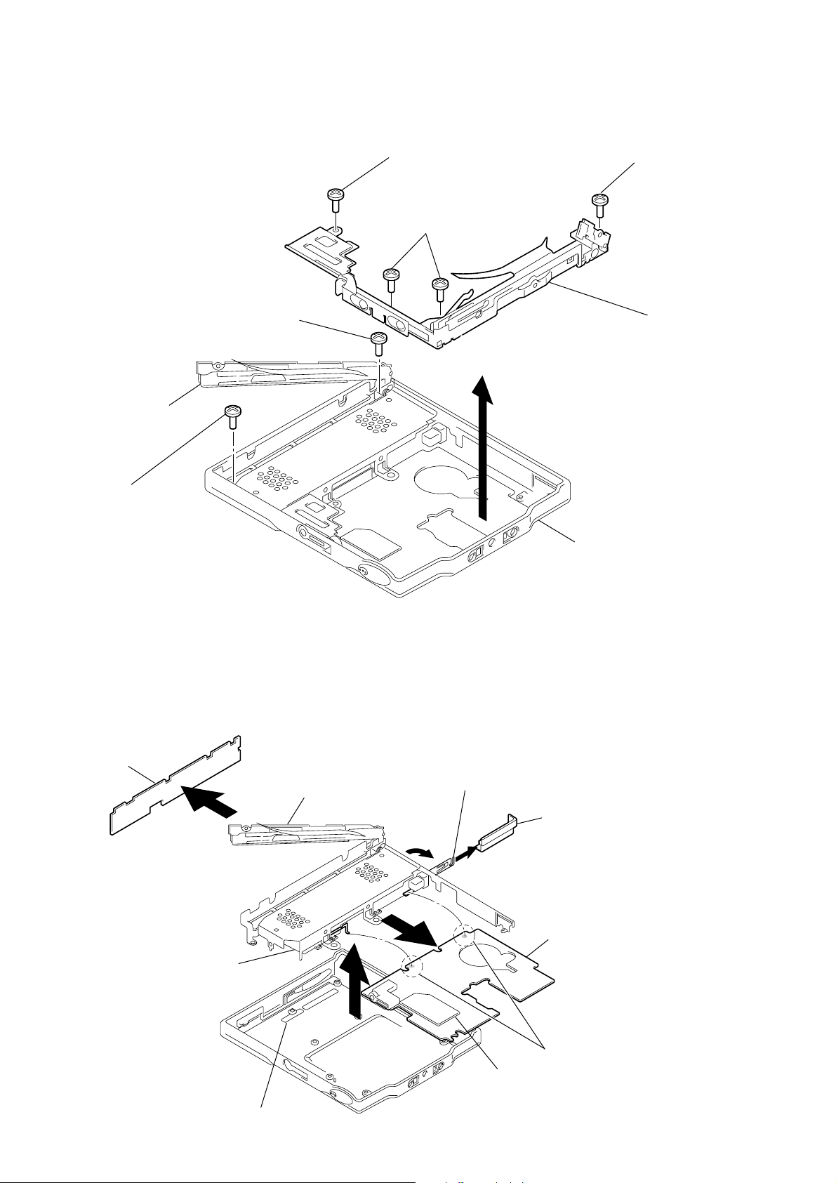
3-3. BRACKET (R) ASSY
1
Screw, ES lock
1
Screws, ES lock
1
Screw, ES lock
3
Screw, ES lock
Bracket (L) ASSY
3
Screw, ES lock
3-4. MAIN BOARD SUB ASSY, BRACKET (L) ASSY,
SW BOARD
Note : On installation of bottom panel assy, adjust the position of
both two switches (S807, S808) and two knobs (AVLS,
HOLD).
SW board
Bracket (L) ASSY
7
Bracket (R) ASS
2
Panel, bottom
MAIN BOARD SUB ASSY
• Audio board is supplied with main board sub ASSY.
• Audio board can't be moved away from main board.
Give a damage when take it off forcibly.
• The part that audio board overlap with main board can't be re-
paired.
2
Claw
3
Lid, battery case
1
Case (K), battery
Knob (HOLD)
4
6
(Audio board)
Main board sub ASS
5
Remove solder
(Two places)
6
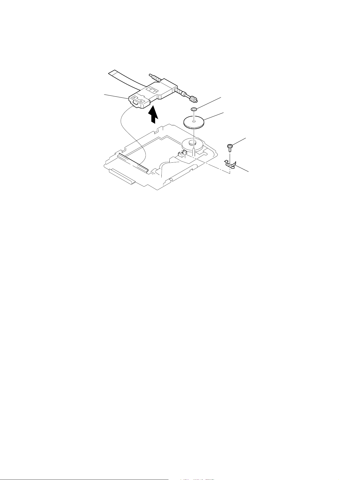
3-5. OPTICAL PICK-UP ASSY
t
MZ-E909
Optical pick-up ASSY
(LCX-4E)
5
1
Washer
2
Gear (SA)
3
Screw (MI 1.4)
4
Spring, thrust deten
7
MZ-E909
888
u
008 V1.000
F
1SHUFF PGM
SOUND 1 2 BASS 1 2
All on
All off
Microprocessor
version
display
0
SECTION 4
TEST MODE
4-1. GENERAL
• When entered in the TEST MODE, this set provides the Overall
Adjustment mode which allows CD and MO discs to be automatically adjusted. In the Overall Adjustment mode, the system
discriminates between CD and MO discs, performs adjustments
in sequence automatically, and displays the faulty location if
any fault is found. In the Manual mode, selected adjustments
can be performed automatically.
• The attached remote control is used to operate the TEST MODE.
Unless otherwise specified in the text, the key means that on the
remote control.
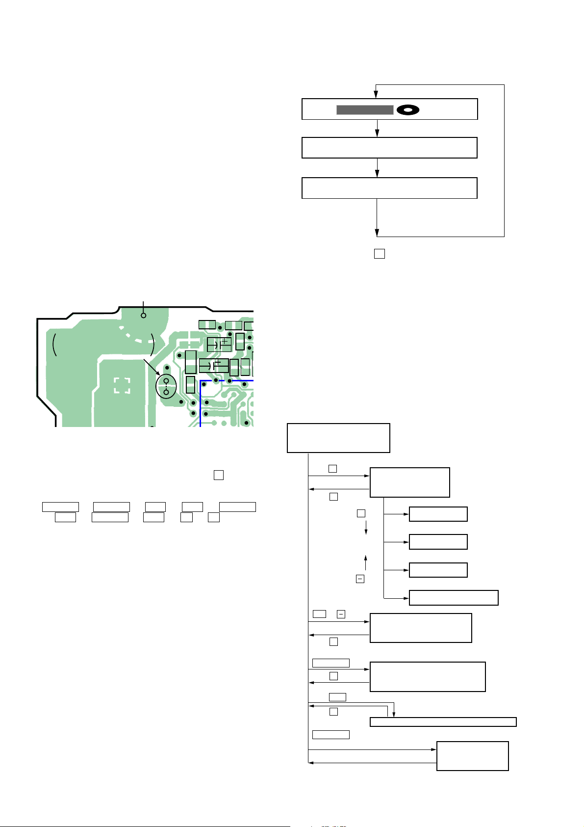
4-2. SETTING THE TEST MODE
4-2-1. How to set the TEST MODE
To set the TEST MODE, two methods are available.
1 Solder bridge and short TAP601 (TEST) on the main board.
Then turn on the power.
MAIN BOARD (SIDE A)
R607
R601
C810
R8
C802
C699
TAP601
SHORT: TEST MODE
OPEN: NORMAL MODE
TP921
C606
C605
C610
C613
Remote control LCD
• Press and hold down X to hold the current display while the
key is being pressed.
4-2-3. How to release the TEST MODE
When method 1 was used:
Turn off the power and open the solder bridge on TAP601 on the
main board.
Note: The solder should be removed clean. The remaining solder
may make a short with the chassis and other part.
When method 2 was used:
Turn off the power.
Note: If electrical adjustment (see page 11) has not been finished
completely, always start in the test mode. (The set cannot
start in normal mode)
2 In the normal mode, operate the keys on the set and those on the
remote control as specified below:
Turn on HOLD switch on the set. Holding down x (STOP)
key on the set, press the keys on the remote control in the
following sequence:
> N t > N t . t . t > N
t . t > N t . t X t X
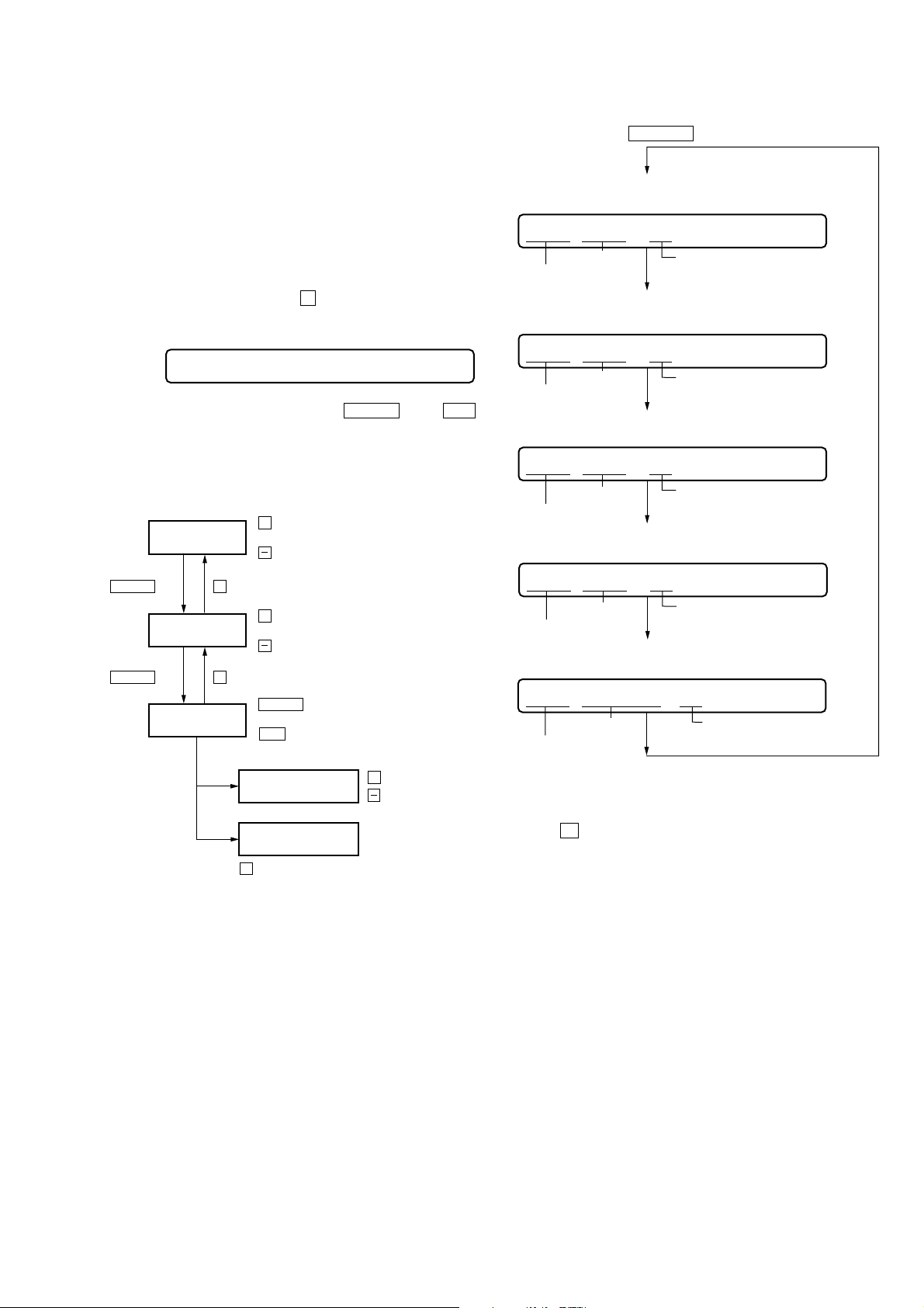
4-2-2. Operations when the TEST MODE is set
When the TEST MODE is entered, the system switches to the display check mode within the TEST MODE. From this mode, the
other Test modes can be accessed.
When the TEST MODE is set, the LCD repeats a cycle of the following displays:
8
4-3. TEST MODE STRUCTURE
Test Mode
(Display Check Mode)
+
key
Manual Mode
x
key
+
key
key
.
or
key
Overall Adjustment Mode
x
key
DISPLAY key
x
key
>B
key
x
key
DISPLAY key
(Press and hold down about 3 sec)
Terminate key checking or open
the top panel.
Self-diagnostic Display Mode
Sound Skip Check Result Display Mode
Servo Mode
Audio Mode
Power Mode
OP Alignment Mode
Key Check Mode
MZ-E909
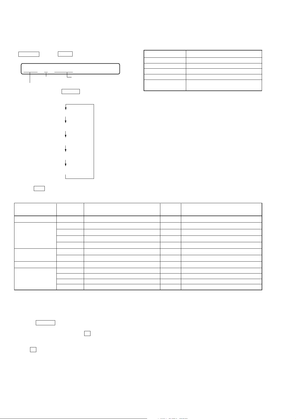
4-4. MANUAL MODE
4-4-1. Outline of the function
The Manual mode is designed to perform adjustments and
operational checks on the set’s operation according to each
individual function.
Usually, no adjustments are made in this mode.
However, the Manual mode is used to clear the memory before
performing automatic adjustments in the Overall Adjustment mode.
4-4-2. How to set the Manual mode
1. Set the TEST MODE and press + key to set the Manual mode.
Remote control LCD display
000 Manual
2. During each test, press and hold down > N key or .
key for a while to move the optical pickup on the sled outer or
inner perimeter.
3. Each test item is assigned with a three-digit item number. The
100th place is a major item, 10th place is a middle item, and unit
place is a minor item.
+
key : 100th place of mode number
increase
key : 100th place of mode number
decrease
keykey
+
key : 10th place of mode number
increase
key : 10th place of mode number
decrease
key
key : Unit place of mode number
> N
increase
.
key : Unit place of mode number
decrease
> N
> N
Change Major
Item
x
Change Middle
Item
key
Change Minor
Item
x
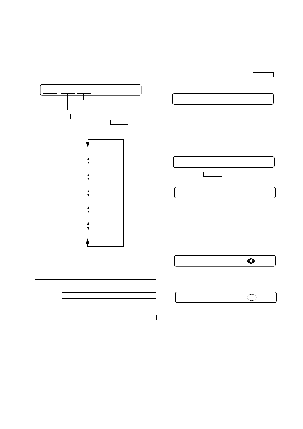
4. During each test mode, the display is changed from one to
another each time DISPLAY key is pressed.
• Address & Adjusted Value Display
LCD display
011 C68S01
mode number
address
• Jitter Value & Adjusted Value Display
LCD display
adjusted value
011 OFFJ01
mode number
jitter value
• Block Error Value & Adjusted Value Display
LCD display
adjusted value
011 063B01
block error value
mode number
• ADIP Error Value & Adjusted Value Display
LCD display
adjusted value
011 059A01
ADIP error value
mode number
• Item Title Display
LCD display
adjusted value
011 LrefPw 0 1
item title
mode number
adjusted value
+
Change Adjustment
Value
Write Adjustment
Value
X
key : When adjusted value is changed :
Adjusted value is written.
When adjusted value is not changed :
That item is adjusted automatically.
key : Up
key : Down
Note: In the Power mode, the item title display is only displayed.
5. To terminate the Manual mode and return to the TEST MODE,
press x key.
4-5. OVERALL ADJUSTMENT MODE
4-5-1. Outline of the function
This mode is designed to adjust the servo system automatically by
going through all the adjustment items.
Usually, this mode is used to perform automatic adjustments when
servicing the set.
For further information, refer to section 5. ELECTRICAL ADJUSTMENTS. (See page 12)
4-6. SELF-DIAGNOSTIC DISPLAY MODE
4-6-1. Outline of the function
The Self-diagnostic system is used in this set. If an error occurs
during playback, this system detects the fault through the
microprocessor’s mechanism and power control blocks and stores
the cause in EEPROM in a history format.
This history, which can be viewed in the TEST MODE, provides
the means of locating the fault in troubleshooting.
9
MZ-E909
4-6-2. Self-diagnostic mode
1. Set the TEST MODE.
2. With all the LCD display segments blinking on the set, press
DISPLAY key and >B key, the Self-diagnostic mode is
entered.
001 1 Adrs
History code
Error display code
3. Hereinafter, each time > N key is pressed, the reference
information display changes as follows:
0XX 1 # # # #
0XX N # # # #
0XX N1 # # # #
Simplified contents
• Contents of the history codes
History code number
1 The first error that occurred.
N The last error that occurred.
N-1 The first error from the last one.
N-2 The second error from the last one.
R
Total recording time ( – – – – is displayed
for MZ-E909)
Contents
0XX N2 # # # #
0XX R
• Press . key to go back to the previous display.
• Description of the error display codes
Contents of fault Display code Meaning of code
No error 00 No error – – – – No error
Servo system error
TOC error
Power system error 22 LOWBATT LBat Instantaneous interruption detected.
Offset error
– – – –
Simplified
contents
01 Access target address illegally specified Adrs An attempt to access an abnormal address.
02 HIGH TEMP Temp HIGH TEMP
03 FOCUS ERROR Fcus Focus off-center.
04 SPINDLE ERROR Spdl Abnormal rotation of disc
11 TOC ERROR TOC
12 READ DATA ERROR Data
31 OFFSET ERROR Ofst Offset error
32 FE_ABCD_OFFSET_ERR ABCD FE ABCD Offset error
33 TE_ABCD_OFFSET_ERR TE TE ABCD Offset error
34 X1_TE_OFFSET_ERR X1TE X1 TE ABCD Offset error
Description
4-6-3. Clearing the error display code
After servicing, reset the error display code.
1. Set the TEST MODE.
2. Press the DISPLAY key on the remote control activates the selfdiagnosis display mode.
3. To reset the error display code press X key on the remote control when the code is displayed.(except for R - - - - display)
(All the data on the 1st, N, N-1 and N-2 will be reset)
4. Press X key on the remote control again.
10
MZ-E909
4-7. SOUND SKIP CHECK RESULT DISPLAY MODE
This set can display and check the error count occurring during
play.
• Setting method of Sound Skip Check Result Display Mode
1. Setting the test mode.
2. Press the > N key activates the sound skip check result
display mode where the LCD displays as shown below.
LCD display
000 P**P##
Total of play system
error count
Total of record system error count
3. When > N key is pressed, the total of error count is displayed on the LCD, and each time the > N key is pressed,
the error count descents one by one as shown below. Also, when
. key is pressed, the error count ascends by one.
000 P**R00
000 EIB **
000 Stat**
4-8. KEY CHECK MODE
4-8-1. Outline of the function
This mode is used to check to make sure that each of the keys
(including the slide switch) on the set operates normally.
4-8-2. Setting the Key Check mode
1. Set the TEST MODE. Press and hold down DISPLAY key (for
more than 3 sec) to set the Key Check mode.
LCD display
000 0F
2. When each key on the set and on remote control is pressed, its
name is displayed on the LCD. (The operated position is displayed for 4 sec after the slide switch is operated. If any other
key is pressed during this display, the LCD switches to its name
display)
Example: When > N key on the set is pressed:
LCD display
000 FF 0F
Example: When > N key on the remote control is pressed:
LCD display
000 rPLAY XX
000 Adrs**
000 BEmp**
000 ######
P**R00 : Total of play system error and record system error count
** : Sound skip check items counter (hexadecimal)
##### : 6-digit address (hexadecimal) where a sound skipped
Error code
Cause of error Description of error
Playback EIB Sound error correction error
Stat Decorder status error
Adrs Cannot access the address
BEmp Buffer becomes empty
4. Quit the sound skip check result display mode, and press the x
key to return to the test mode. (display check mode)
XX: AD value of the remote control key (hexadecimal 00 to FF)
3. When all the keys on the set and on the remote control are considered as OK, the following displays are shown for 2 sec.
(The key pressed to enter the Key Check mode has been checked
even if it is not pressed in this mode)
Example: When the keys on the set are considered as OK:
LCD display
888 SET OK OF
Example: When the keys on the remote control are considered
as OK:
LCD display
888 RMC OK OX
4. When all the key have been checked or when the top panel is
opened during this checking, the system terminates the Key
Check mode and return to the TEST MODE.
11
MZ-E909
SECTION 5
ELECTRICAL ADJUSTMENTS
5-1. GENERAL
In this set, CD and MO discs can be automatically adjusted by setting the Overall Adjustment mode within the TEST MODE,
Before performing these automatic adjustments, it is necessary to
clear the memory and adjust the power in the Manual mode.
5-2. NOTES FOR ADJUSTMENT
5-2-1. Jigs
• CD disc TDYS-1 (part code: 4-963-646-01)
• MO disc PTDM-1 (part code: J-2501-054-A)
or commercially available MO disc (recorded)
• Digital voltmeter
5-2-2. Adjustment sequence
The adjustments should be always performed in the following
sequence:
1 Reset NV (Clear the memory)
Manual mode
2 Manual power adjustments
3 Electrical offset adjustments
(Do not enter the disc)
4 Overall CD adjustments
5 Overall MO adjustments
Overall adjustment mode
5-4. MANUAL POWER ADJUSTMENTS
5-4-1. Adjustment sequence
The adjustments should be always performed in the following sequence:
1 Vc PWM Duty (L) adjustment (item No.:762)
r
2 Vl PWM Duty adjustment (item No.:764)
r
3 Vd PWM Duty adjustment (item No.:765)
5-4-2. Vc PWM Duty (L) adjustment method
1. Confirm that the power voltage is at 1.5 V DC.
2. Set the TEST MODE.
3. Set the overall adjustment mode and press PLAY MODE key,
item No. will change to 762.
LCD display
762 VclPWM XX
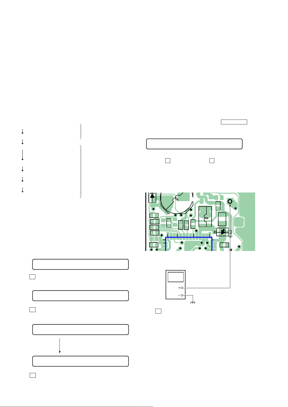
4. Connect a digital voltmeter to TP901 (VC) on the main board
and adjust + key (voltage up) and – key (voltage down) on
the remote control.
Adjustment value:2.35V
Standard value:2.34 to 2.355V
6 RESUME clear
7 Rewrite the NV value
5-2-3. Power
The power is supplied with 1.5 V DC from the battery case.
5-3. RESET NV
5-3-1. How to reset NV
1. Set the TEST MODE.
2. Set the Manual mode and set the item No. 021, Reset NV.
LCD display
021 Res NV CC
3. Press X key on the remote control.
LCD display
021 Res OK?
4. Press X key on the remote control again.
LCD display
MAIN BOARD (SIDE A)
R909
C921
C908
R903
C905
5. Press X key to write the adjustment value.
C909
29
30
digital voltmeter
C910
R910
IC901
R951
TP901 (VC)
L905
15202528
14
R965
R964
TP901
(VC)
C907
D903
021 Res ***
After reset is completed.
021 Reset!
5. Press x key to terminate the Manual mode and return to the
TEST MODE.
12
 Loading...