

Sony MZE-90 Service manual
MZ-E90
SERVICE MANUAL
Ver 1.0 1999. 11
(Photo: Silver)
US and foreign patents licensed from Dolby
Laboratories Licensing Corporation.
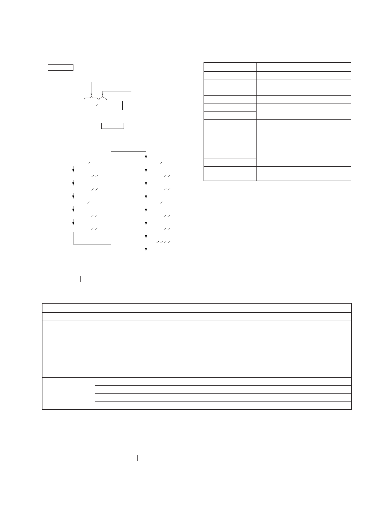
SPECIFICATIONS
System
Audio playing system
MiniDisc digital audio system
Laser diode properties
Material: GaAlAs
Wavelength: λ = 790 nm
Emission duration: continuous
Laser output: less than 44.6 µW
(This output is the value measured at a distance
of 200 mm from the objective lens surface on the
optical pick-up block with 7 mm aperture.)
Revolutions
600 rpm to 2250 rpm
Error correction
Advanced Cross Interleave Reed Solomon
Code (ACIRC)
Sampling frequency
44.1 kHz
Coding
Adaptive TRansform Acoustic Coding (ATRAC)
Modulation system
EFM (Eight to Fourteen Modulation)
Number of channels
2 stereo channels
1 monaural channel
Frequency response
20 to 20,000 Hz ± 3 dB
Wow and Flutter
Below measurable limit
Outputs
Headphones: stereo mini-jack,
maximum output level 5 mW + 5 mW, load
impedance 16 ohm
E Model
Tourist Model
Model Name Using Similar Mechanism NEW
MD Mechanism Type MT-MZE90-166
Optical Pick-up Mechanism Type LCX-2E
General
Power requirements
Nickel metal hydride rechargeable battery
NH-14WM (supplied)
One LR6 (size AA) battery (not supplied)
Sony AC Power Adaptor AC-E15L* (not
supplied) connected to the DC IN 1.5V jack
Battery operation time
Battery life*
Batteries Playback
Ni-MH Approx. 21 hours**
rechargeable battery
(NH-14WM)
One LR6 (size AA) Approx. 31 hours
alkaline battery
One LR6 (size AA) Approx. 56 hours**
alkaline battery
and a Ni-MH
rechargeable battery
(NH-14WM)
* The battery life may be shorter depending on
operating conditions and the temperature of the
location.
** With a fully charged battery
– Continued on next page –
MICROFILM
PORTABLE MINIDISC PLAYER
– 1 –
Dimensions
Approx. 78.4 × 13.5 × 71.5 mm (w/h/d)
(3 1/8 × 9/16 × 2 7/8 in.) not including projecting
parts and controls
Mass
Approx. 70 g (2.5 oz.) the player only
Approx. 113 g (4.0 oz.) incl. a premastered MD
and a nickel metal hydride rechargeable battery
NH-14WM
Supplied accessories
Battery Charger (1)
Rechargeable battery (1)
Rechargeable battery carrying case (1)
Headphones with a remote control (1)
Dry battery case (1)
Carrying pouch (1)
AC Plug Adaptor (1) (World model only)
Design and specifications are subject to change without notice.
Precautions for Laser Diode Emission Check
When checking the emission of the laser diode during adjustments, never view directly downwards as this may lead to
blindness.
Precautions for Using Optical Pick-up (LCX-2E)
As the laser diode inside the optical pick-up damages by static
electricity easily, solder the laser tap of the Optical pick-up
flexible board when handling. Also take the necessary measures
to prevent damages by static electricity. Handle the Optical pickup flexible board with care as it breaks easily.
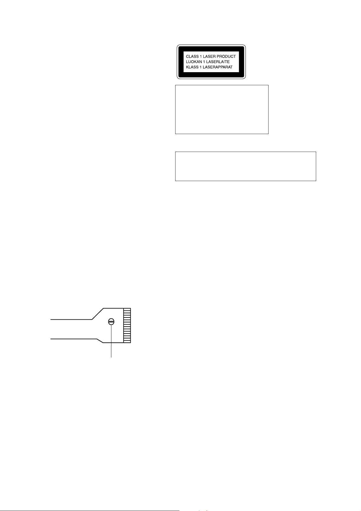
This MiniDisc player is classified as a CLASS 1 LASER
product.
The CLASS 1 LASER
PRODUCT label is located on
the bottom exterior.
IN NO EVENT SHALL SELLER BE
LIABLE FOR ANY DIRECT,
INCIDENTAL OR CONSEQUENTIAL
DAMAGES OF ANY NATURE, OR
LOSSES OR EXPENSES RESULTING
FROM ANY DEFECTIVE PRODUCT
OR THE USE OF ANY PRODUCT.
“MD WALKMAN” is a trademark of Sony
Corporation.
CAUTION
Use of controls or adjustments or performance of procedures
other than those specified herein may result in hazardous
radiation exposure.
Flexible Circuit Board Repairing
• Keep the temperature of the soldering iron around 270°C
during repairing.
• Do not touch the soldering iron on the same conductor of the
circuit board (within 3 times).
• Be careful not to apply force on the conductor when soldering
or unsoldering.
Notes on chip component replacement
• Never reuse a disconnected chip component.
• Notice that the minus side of a tantalum capacitor may be
damaged by heat.
Laser tap
Optical Pick-up flexible board
SAFETY-RELATED COMPONENT WARNING!!
COMPONENTS IDENTIFIED BY MARK 0 OR DOTTED LINE WITH
MARK 0 ON THE SCHEMATIC DIAGRAMS AND IN THE PARTS
LIST ARE CRITICAL TO SAFE OPERATION.
REPLACE THESE COMPONENTS WITH SONY PARTS WHOSE
PART NUMBERS APPEAR AS SHOWN IN THIS MANUAL OR IN
SUPPLEMENTS PUBLISHED BY SONY.
– 2 –

TABLE OF CONTENTS
1. SERVICING NOTE......................................................... 4
2. GENERAL.........................................................................5
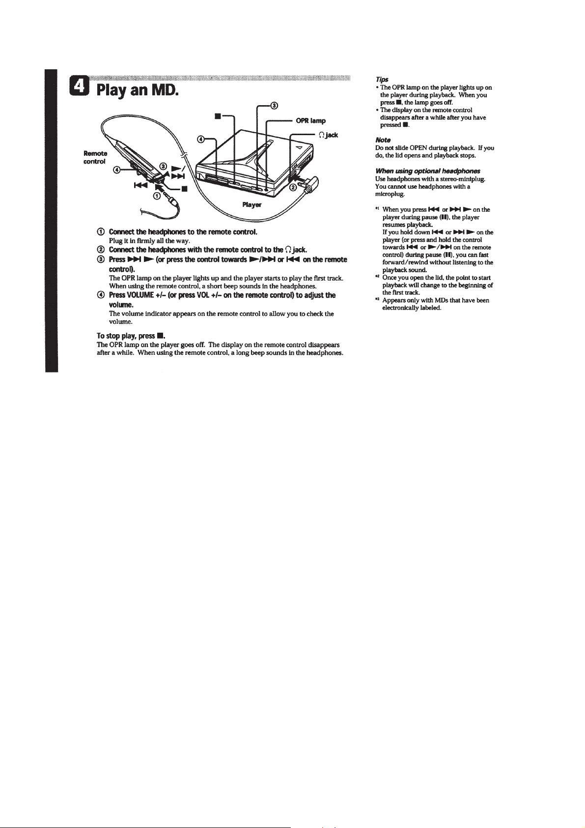
Playing an MD right away! ................................................... 5
3. DISASSEMBLY ............................................................... 7
3-1. Lid Assy, Upper .................................................................... 7
3-2. Holder Assy...........................................................................7
3-3. Mechanism Deck .................................................................. 8
3-4. System Board ........................................................................ 8
3-5. “Plate (L) Assy, Fulcrum”, “Plate (R) Assy, Fulcrum”.........9
3-6. SW Board, Main Board ........................................................ 9
3-7. Service Assy, OP ................................................................. 10
4. TEST MODE................................................................... 11
4-1. General ................................................................................ 11
4-2. Setting the TEST MODE .................................................... 11
4-2-1. How to Set the TEST MODE ...................................... 11
4-2-2. Operations when the TEST MODE is set ................... 11
4-2-3. How to release the TEST MODE ................................ 11
4-3. Test Mode Structure............................................................11
4-4. Manual Mode ...................................................................... 12
4-4-1. Outline of the function ................................................ 12
4-4-2. How to set the Manual Mode ...................................... 12
4-5. Overall Adjustment Mode ................................................... 12
4-5-1. Outline of the Function ............................................... 12
4-6. Self-diagnostic Display Mode ............................................ 12
4-6-1. Outline of the Function ............................................... 12
4-6-2. Self diagnostic Mode ................................................... 13
4-6-3. Clearing the Error Display Code ................................. 13
4-7. Key Check Mode ................................................................ 14
4-7-1. Outline of the Function ............................................... 14
4-7-2. Setting the Key Check Mode ....................................... 14
6. DIAGRAMS..................................................................... 18
6-1. IC Pin Descriptions ............................................................. 18
6-1-1. IC801 CXR701080-006GA (System Control) ............ 18
6-2. Block Diagrams .................................................................. 21
6-2-1. MD Block Diagram ..................................................... 21
6-2-2. Servo Block Diagram .................................................. 23
6-2-3. System Control Block Diagram .................................. 25
6-3. Printed Wiring Boards and Schematic Diagrams................ 27
6-3-1. Printed Wiring Board – Main Board – ........................ 27
6-3-2. Schematic Diagram – Main Board (1/4) ..................... 31
6-3-3. Schematic Diagram – Main Board (2/4) – .................. 33
6-3-4. Schematic Diagram – Main Board (3/4) – .................. 35
6-3-5. Schematic Diagram – Main Board (4/4) – .................. 37
6-3-6. Printed Wiring Board – System Board – ..................... 39
6-3-7. Schematic Diagram – System Board – ........................ 41
6-3-8. Printed Wiring Board – SW Board –........................... 43
6-3-9. Schematic Diagram – SW Board –..............................45
6-4. IC Block Diagrams ............................................................. 46
7. EXPLODED VIEWS..................................................... 49
7-1. Main Unit Section ............................................................... 49
7-2. Mechanism Deck Section ................................................... 50
8. ELECTRICAL PARTS LIST...................................... 51
5. ELECTRICAL ADJUSTMENTS..............................15
5-1. General ................................................................................ 15
5-2. Notes for Adjustment .......................................................... 15
5-2-1. Jigs ............................................................................... 15
5-2-2. Adjustment sequence ...................................................15
5-2-3. Power ........................................................................... 15
5-3. Reset NV ............................................................................. 15
5-3-1. How to Reset NV ........................................................ 15
5-4. Manual Power Adjustments ................................................ 15
5-4-1. Adjustment sequence ...................................................15
5-4-2. Vc PWM Duty (L) Adjustment Method...................... 15
5-4-3. Vrem PWM Duty (L) Adjustment Method.................. 15
5-4-4. Vc PWM Duty (H) Adjustment Method ..................... 16
5-4-5. Vrem PWM Duty (H) Adjustment Method................. 16
5-5. Overall Adjustment Mode ................................................... 16
5-5-1. Overall Adjustment Mode Structure............................ 16
5-5-2. Overall CD and MO adjustment Method .................... 16
5-5-3. Overall CD and MO adjustment Items ........................ 17
– 3 –
SECTION 1
SERVICING NOTE
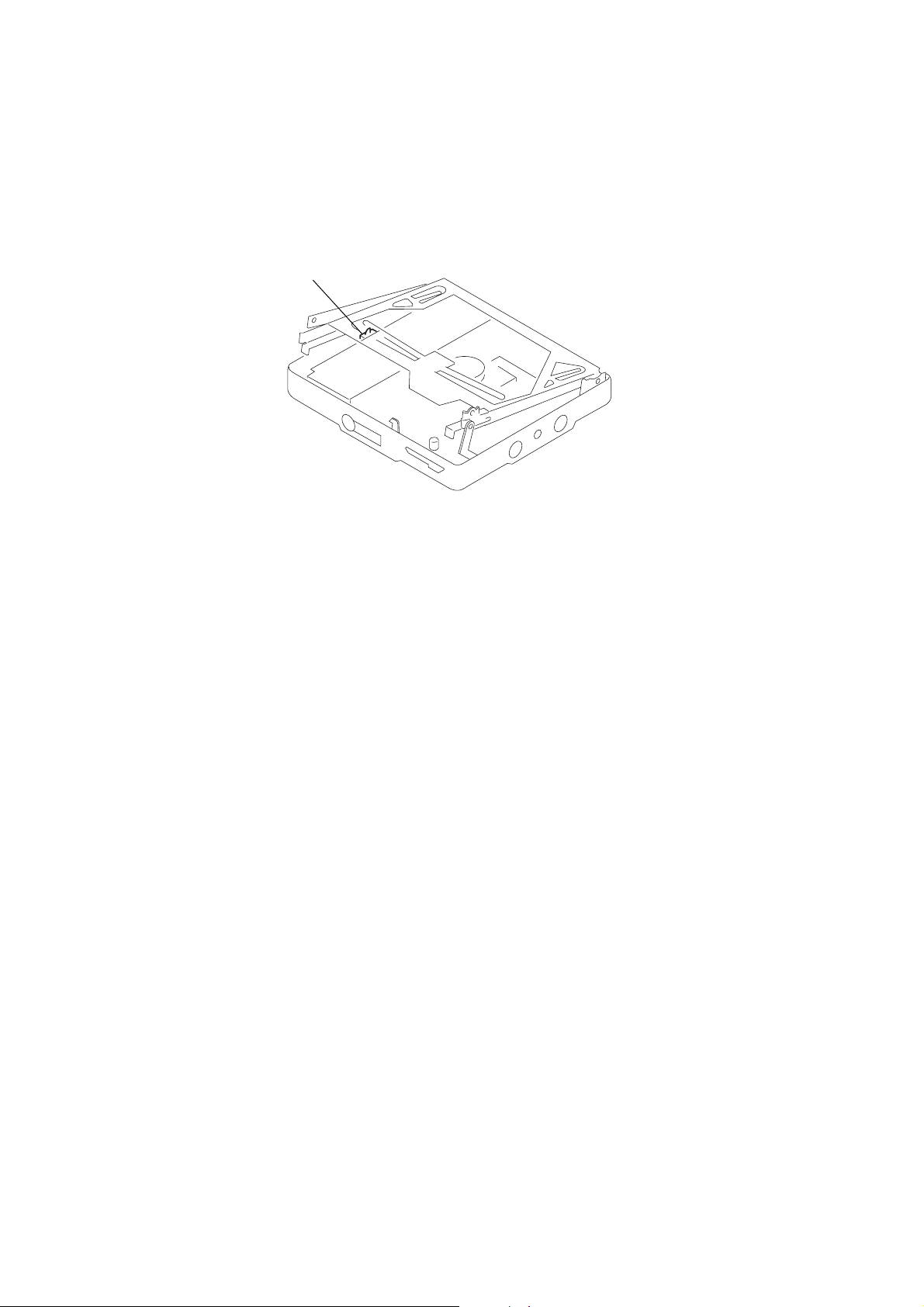
1) When repairing this device with the power on, if you remove
the main board or open the upper panel assy, this device stops
working.
In this case, you can work without the device stopping by
fastening the hook of the OPEN/CLOSE switch (SW board
S809) with tape.
SW board S809
2) This set is designed to perform automatic adjustment for each
adjustment and write its value to EEPROM. Therefore, when
EEPROM (SYSTEM board IC802) has been replaced in
service, be sure to perform automatic adjustment and write
resultant values to the new EEPROM.
Refer to section 5 Test Mode (page 11) for details.
– 4 –

SECTION 2
GENERAL
This section is extracted from
instruction manual.
– 5 –
– 6 –

SECTION 3
r
t
DISASSEMBLY
Note : This set can be disassemble according to the following sequence.
Set Lid Assy, Upper Holder Assy Mechanism Deck
Note : Follow the disassembly procedure in the numerical order given.
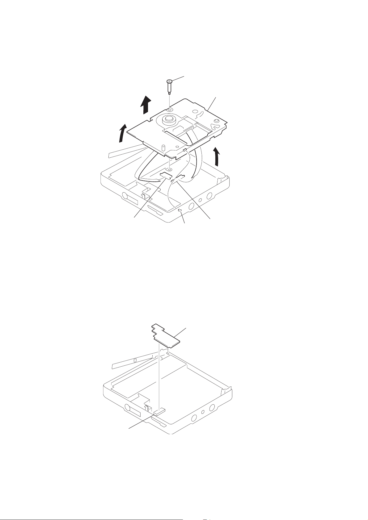
3-1. LID ASSY, UPPER
4
screw(1.7),MI
“Plate (L) Assy, Fulcrum ”,
“ Plate (R) Assy, Fulcrum”
System Board
Service Assy, OP
5
lid assy, uppe
SW Board,
Main Board
3-2. HOLDER ASSY
3
screw(1.7),MI
2
1
3
holder assy
2
shaft
– 7 –
1
shaf
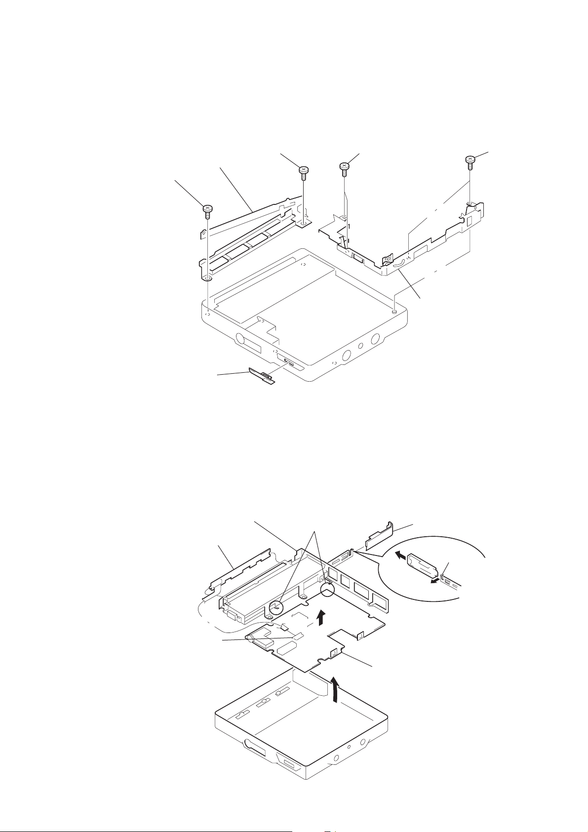
3-3. MECHANISM DECK
k
1
screw, step
3
6
CN551
4
claw
7
mechanism dec
2
5
connector
3-4. SYSTEM BOARD
1
CN601
2
SYSTEM board
– 8 –
3-5. “PLATE (L) ASSY, FULCRUM”, “PLATE (R) ASSY, FULCRUM”
Note: When installing, fit the knob (OPEN).
1
2
screw(1.7),MI
3
plate (L) assy, fulcrum
screw(1.7),MI
4
M 1.4
6
plate (R) assy, fulcrum
5
M 1.4
7
knob (open)
3-6. SW BOARD, MAIN BOARD
Note: When installing, fit the knobs (HOLD, MB, AVLS).
8
case, battery
6
SW board
5
CN802
7
removal the solders.
4
2
lid , battery case
claw
1
– 9 –
3
9
MAIN board
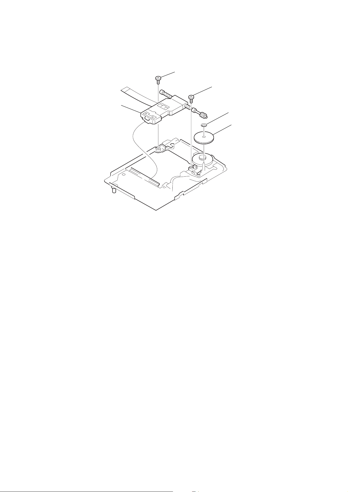
3-7. SERVICE ASSY, OP
)
5
service assy, OP
4
M 1.4
3
M 1.4
1
washer
2
gear (SA
– 10 –

SECTION 4
TEST MODE
4-1. GENERAL
• When entered in the TEST MODE, this set provides the Overall
Adjustment mode which allows CD and MO discs to be automatically adjusted. In the Overall Adjustment mode , the system
discriminates between CD and MO discs, performs adjustments
in sequence automatically, and displays the faulty location if any
fault is found. In the Manual mode, selected adjustments can be
performed automatically.
• The attached remote control is used to operate the TEST MODE.
Unless otherwise specified in the text, the key means that on the
remote control.
4-2. SETTING THE TEST MODE
4-2-1. How to set the TEST MODE
T o set the TEST MODE, two methods are available.
1 Solder bridge and short BP801 (TEST) on the system board.
Then turn on the power.
SYSTEM BOARD (SIDE A )
TP821
TP816
TP823
TP822
TP819
TP820
TP818
Remote control LCD
888
u
All on
All off
004 V1.100
Microprocessor
version
display
• Press and hold down X to hold the current display while the key
is being pressed.
4-2-3. How to release the TEST MODE
When method 1 was used:
Turn off the power and open the solder bridge on BP801on the
system board.
Note: The solder should be removed clean. The remaining
solder may make a short with the chassis and other part.
When method 2 was used:
Turn off the power.
BP801
1-675-487-
BP801
2 In the normal mode, operate the keys on the set and those on the
remote control as specified below:
Turn on HOLD switch on the set. Holding down x (STOP)
key on the set, press the keys on the remote control in the
following sequence:
> N t > N t . t . t > N
t . t > N t . t X t X
4-2-2. Operations when the TEST MODE is set
When the TEST MODE is entered, the system switches to the
display check mode within the TEST MODE. From this mode, the
other Test modes can be accessed.
When the TEST MODE is set, the LCD repeats a cycle of the
following displays:
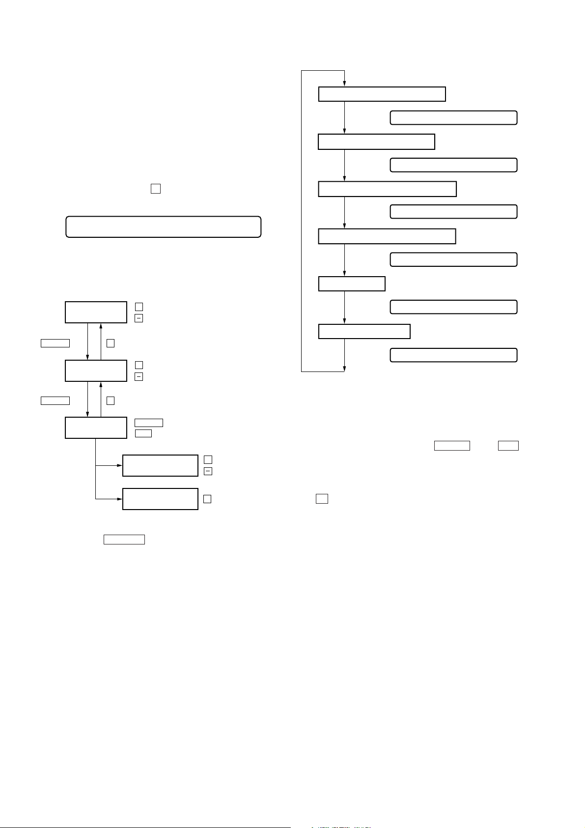
4-3. TEST MODE STRUCTURE
Test Mode
(Display Check Mode)
+
key
Manual Mode
x
key
+
key
key
key
Overall Adjustment Mode
x
key
DISPLAY key
Self-diagnostic Display Mode
x
key
DISPLAY key
(Press and hold down about 3 sec.)
Terminate key checking or open
the top panel.
Servo Mode
Audio Mode
Power Mode
OP Alignment Mode
Key Check Mode
– 11 –
4-4. MANUAL MODE
4-4-1. Outline of the function
The Manual mode is designed to perform adjustments and
operational checks on the set’s operation according to each
individual function.
Usually, no adjustments are made in this mode.
However, the Manual mode is used to clear the memory before
performing automatic adjustments in the Overall Adjustment mode.
4-4-2. How to set the Manual mode
1. Set the TEST MODE and press + key to set the Manual mode.
Remote control LCD display
888 Manual
2. Each test item is assigned with a three-digit item number. The
third digit stands for a major item, the second digit for a middle
item, and the first digit for a moniro item.
+
> N
Change Major
Item
x
Change Middle
Item
keykey
key : Up
key : Down
+
key : Up
key : Down
Address Value & Adjustment Value
LCD display
011 C68S01
Jitter Value & Adjustment Value
LCD display
011 0FFJ01
Block Error Value & Adjustment Value
LCD display
011 063B01
ADIP Error Value & Adjustment Value
LCD display
011 059A01
Item Title Display
LCD display
011 LrefPw
Power Adjustment Value
LCD display
731 AD 85
x
> N
key
Change Minor
Item
key
key : Up
> N
.
key : Down
Change Adjustment
Value
Write Adjustment
Value
+
key : Up
key : Down
X
key : Write
3. During each test mode, the display is changed from one to
another each time DISPLAY key is pressed.
Note: In the Power mode, the power adjustment value is only
displayed.
4. During each test, press and hold down > N key or .
key for a while to move the optical pickup on the sled outer or
inner perimeter.
5. To terminate the Manual mode and return to the TEST MODE,
press x key.
4-5. OVERALL ADJUSTMENT MODE
4-5-1. Outline of the function
This mode is designed to adjust the servo system automatically by
going through all the adjustment items.
Usually, this mode is used to perform automatic adjustments when
servicing the set.
For further information, refer to section 5. ELECTRICAL ADJUST MENTS (page 15).
4-6. SELF-DIAGNOSTIC DISPLAY MODE
4-6-1. Outline of the function
The Self-diagnostic system is used in this set. If an error occurs
during playback, this system detects the fault through the
microprocessor’s mechanism and power control blocks and stores
the cause in EEPROM in a history format.
This history, which can be viewed in the TEST MODE, provides
the means of locating the fault in troubleshooting.
– 12 –
4-6-2. Self-diagnostic mode
1. Set the TEST MODE.
2. With all the LCD display segments blinking on the set, press
DISPLAY key and the Self-diagnostic mode is entered.
History code
Error display code
888
3. Hereinafter, each time > N key is pressed, the reference
information display changes as follows:
888 1st0XX
888 1st100
1st022
888 N-10XX
888 N-1100
• Contents of the history codes
History code number
1st 0 The first error that occurred.
1st 1
1st 2
N 0 The last error that occurred.
N1
N2
N-1 0 The first error from the last one.
N-1 1
N-1 2
N-2 0 The second error from the last one.
N-2 1
N-2 2
REC
Displays 00.
Displays 00.
Displays 00.
Displays 00.
Total recording time (0000 is displayed
for MZ-E90.)
Contents
888 1st200
888 N 0XX
888 N 100
888 N 200
888 N-1200
888 N-20XX
888 N-2100
888 N-2200
888 R 0000
(Turn back)
• Press . key to go back to the previous display.
• Description of the error display codes
Contents of fault Display code Meaning of code Description
No error 00 No error
01 Access target address illegally specified An attempt to access an abnormal address.
Servo system error
AUDIO error 12
Power system error
02 HIGH TEMP HIGH TEMP
03 FOCUS ERROR Focus off-center.
04 SPINDLE ERROR Abnormal rotation of disc
11
13
21 INIT LOWBATT Abnormal voltage during initialization
22 LOWBATT Instantaneous interruption detected.
23 LOWBATT NI Instantaneous interruption detected (NiMH).
24 LOWBATT AM Instantaneous interruption detected (AM).
4-6-3. Clearing the error display code
After servicing, reset the error display code.
1. Set the TEST MODE. (See page 11)
2. To reset the error display code, press X key on the remote
control when the code is displayed.
(All the data on the 1st, N, N-1 and N-2 will be reset.)
– 13 –
 Loading...