

Sony MZ-E80 Service manual
MZ-E80
SERVICE MANUAL
Ver 1.1 2000. 05
With SUPPLEMENT-1
(9-927-132-82)
US and foreign patents licensed from Dolby
Laboratories Licensing Corporation.
SPECIFICATIONS
E Model
Tourist Model
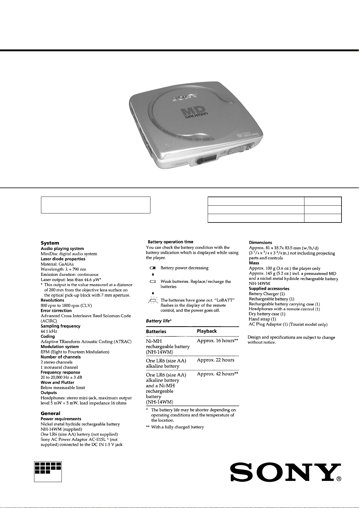
Photo: Silver
Model Name Using Similar Mechanism MZ-E55
Mechanism Type MT-MZE55-150
Optical Pick-Up Name ODX-1B
MICROFILM
PORTABLE MINIDISC PLAYER
SECTION 1
SERVICING NOTES
TABLE OF CONTENTS
1. SERVICING NOTES............................................... 2
2. GENERAL ................................................................... 3
3. DISASSEMBLY ......................................................... 4
4. TEST MODE.............................................................. 6
5. ELECTRICAL ADJUSTMENTS......................... 10
6. DIAGRAMS
6-1. Block Diagram ................................................................ 11
6-2. Printed Wiring Boards .................................................... 16
6-3. Schematic Diagram ......................................................... 19
6-4. IC Pin Function Description ........................................... 28
7. EXPLODED VIEWS ................................................ 35
8. ELECTRICAL PARTS LIST ............................... 37
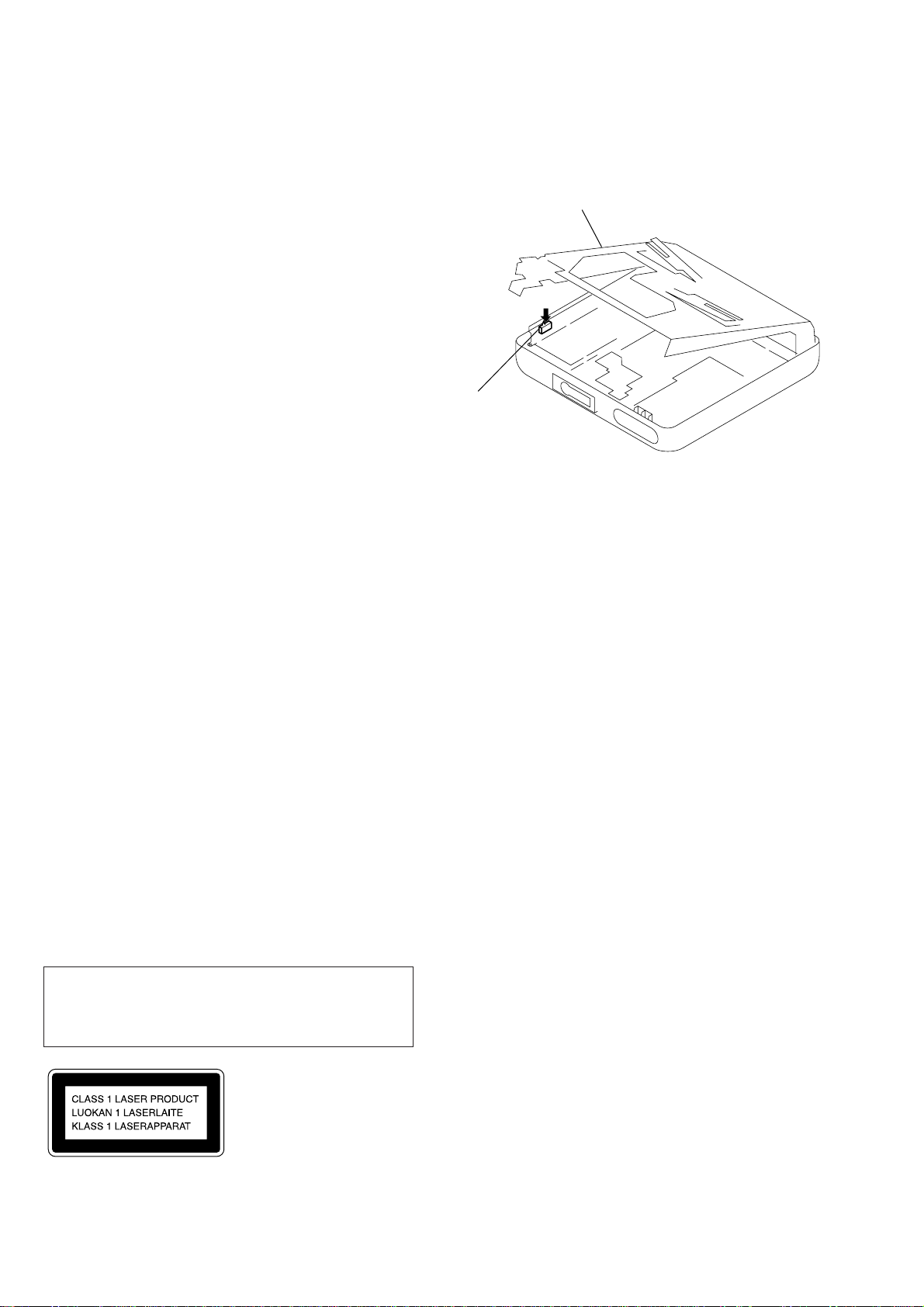
• Removing the mechanism deck causes this set to be disabled
during a repair with the power supplied to the set. Therefore,
lock convex portion of open/close detect switch (S801) during
a repair.
Mechanism deck section
Open/close detect
switch (S801)
• Replacement of CXD2663GA (IC601) used in this set requires
a special tool. Therefore, it cannot be replaced.
Flexible Circuit Board Repairing
• Keep the temperature of the soldering iron around 270 ˚C during repairing.
• Do not touch the soldering iron on the same conductor of the
circuit board (within 3 times).
• Be careful not to apply force on the conductor when soldering
or unsoldering.
Notes on chip component replacement
• Never reuse a disconnected chip component.
• Notice that the minus side of a tantalum capacitor may be damaged by heat.
CAUTION
Use of controls or adjustments or performance of procedures
other than those specified herein may result in hazardous radiation exposure.
This MiniDisc player is classified as a CLASS 1
LASER product.
The CLASS 1 LASER PRODUCT label is located
on the bottom exterior.
SAFETY-RELATED COMPONENT WARNING!!
COMPONENTS IDENTIFIED BY MARK ! OR DOTTED
LINE WITH MARK ! ON THE SCHEMATIC DIAGRAMS
AND IN THE PARTS LIST ARE CRITICAL TO SAFE
OPERATION. REPLACE THESE COMPONENTS WITH
SONY PARTS WHOSE PART NUMBERS APPEAR AS
SHOWN IN THIS MANU AL OR IN SUPPLEMENTS PUBLISHED BY SONY.
– 2 –
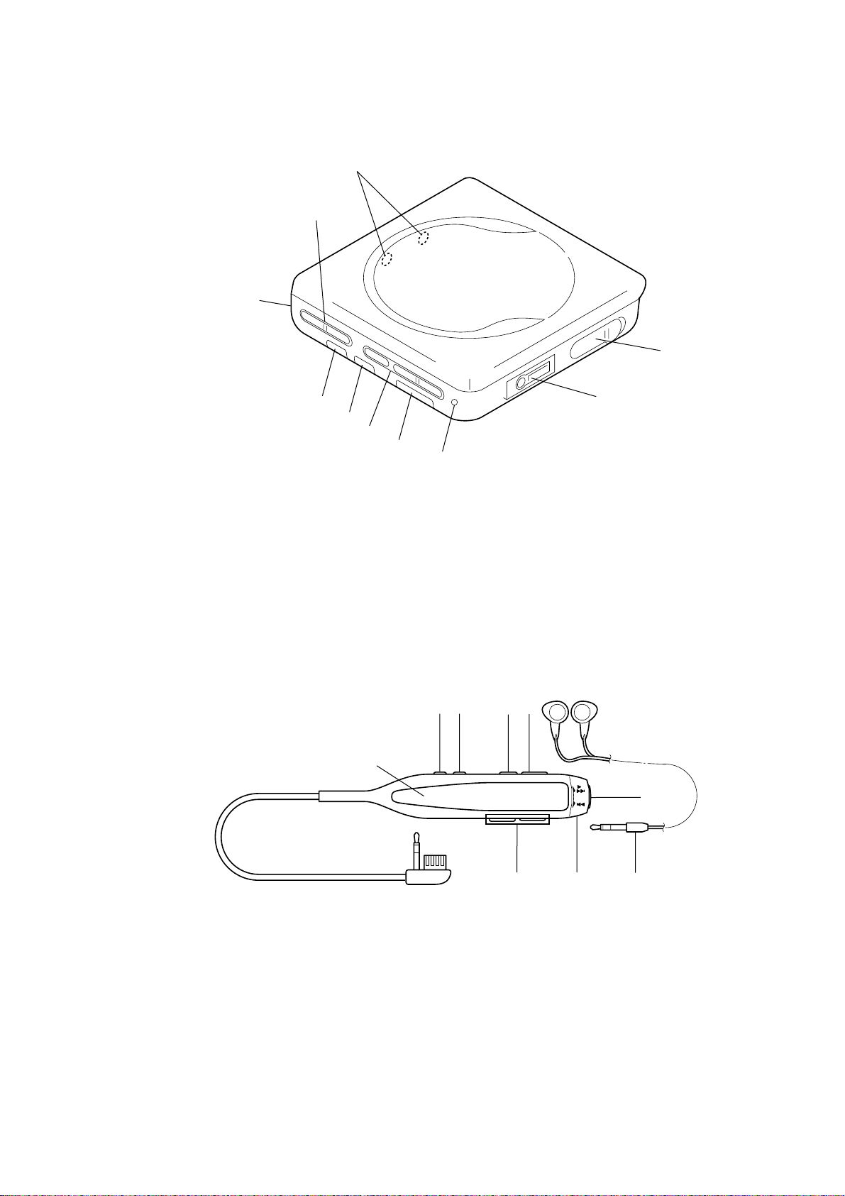
• LOCATION OF CONTROLS
– Main Unit –
5
SECTION 2
GENERAL
8
6
9
4
1 OPERATE indicator
2 HOLD switch
3 DIGITAL MEGABASS switch
4 AVLS switch
5 Battery cover
6 VOLUME +/– buttons
– Remote commander with headphone –
3
7
4
2
1
7 MD operate buttons
+/” ( FF • PLAY )
= (REW )
p (STOP)
8 External battery terminal (+/–)
9 OPEN switch
!º 2 REMOTE jack
5
6
7
8
0
9
3
1 Headphone
2 MD operate switch
”/+ (PLAY • FF)
= (REW)
3 VOL +/– buttons
4 Display window
5 DISPLAY button
6 PLAYMODE button
7 P (PAUSE) button
8 HOLD c switch
9 p (STOP) button
– 3 –
21
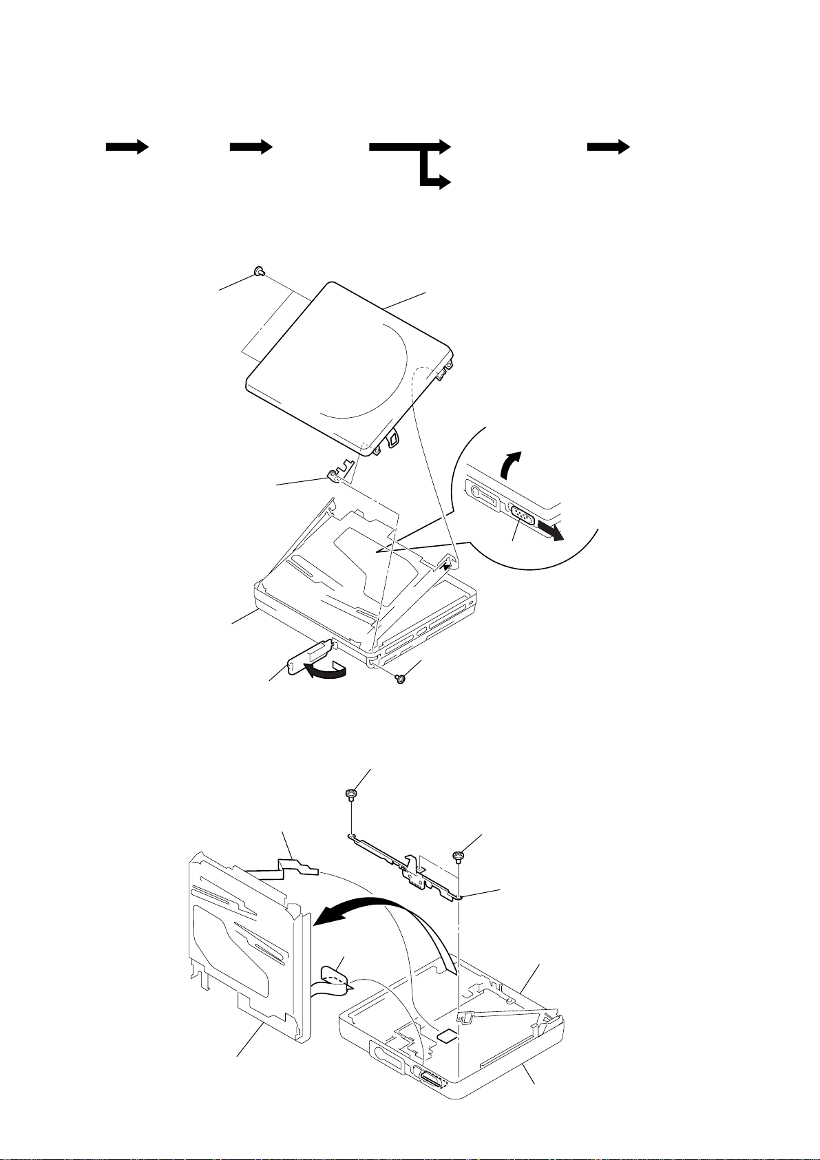
DISASSEMBLY
• This set can be disassembled in the order shown below.
SECTION 3
Set
Note: Follow the disassembly procedure in the numerical order given.
Upper lid assy
Mechanism deck
section
(MT-MZE55-150)
UPPER LID ASSY
5
two screws
(M1.4
×
1.6)
6
fulcrum plate (L)
assy
Optical pick-up section
7
upper lid assy
2
SW boardMain Board, Audio board
main section
3
lid
(battery case)
MECHANISM DECK SECTION (MT-MZE55-150)
3
flexible board
(CN551)
4
flexible board
(CN501)
1
screw
(B1.4
screw (M1.4 × 1.3)
4
×
3)
1
knob (open)
1
two screws
(B1.4
2
×
2.3)
Open slider assy
main board
5
mechanism deck section
main section
– 4 –
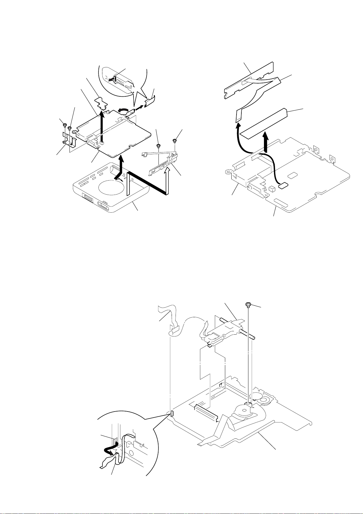
MAIN BOARD, AUDIO BOARD
y
9
audio board
*
1
battery case
4
screw
(B1.4
×
4
screw
(B1.4
5
×
bracket
2.3)
2.5)
8
main board
3
1
claw
2
lid (battery case)
6
screw
(1.4
×
2)
6
screw
(1.4
7
fulcrum plate
(R) assy
SW BOARD
3
×
3)
battery case
SW board
2
flexible board
*
2
1
caution label
*
1 Note: In removing the Audio board, raise the
connector section uprightly.
OPTICAL PICK-UP SECTION
bottom panel ass
2
flexible board
main board
*
2 Note: If the SW board or flexible board is removed,
the caution label (4-213-092-01) on the flexible board will be defaced or deformed, and
replace it with a new label.
4
optical pick-up
section
3
screw
(M1.4
×
2.5)
adhesive sheet
1
flexible board
chassis assy
– 5 –
SECTION 4
TEST MODE
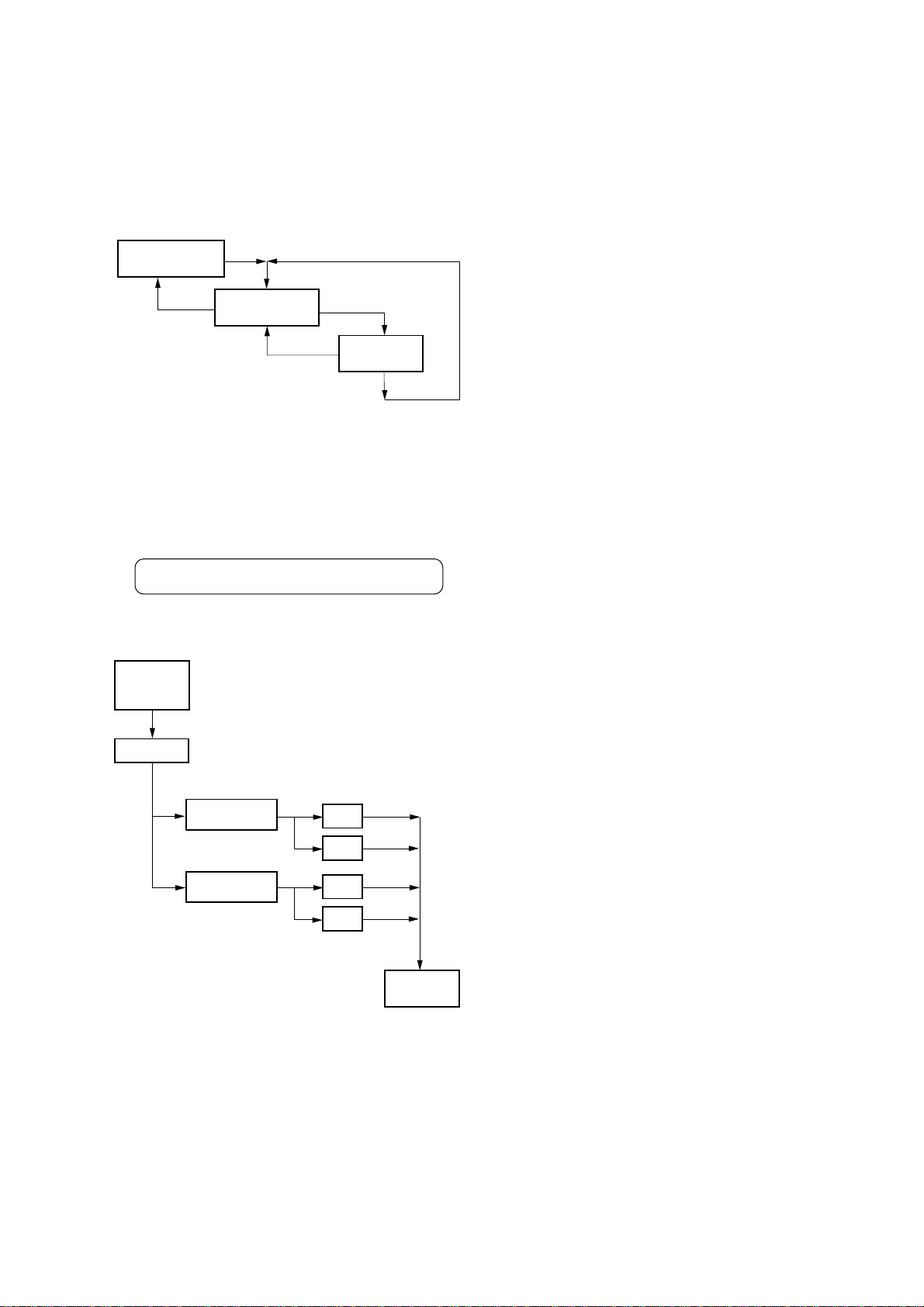
Outline
• In this set, overall adjustment mode is made available by entering test mode to perform automatic adjustment of CD and MO.
In the overall adjustment mode, the disc is determined whether
it is CD or MO and adjustments are performed in sequence. If a
fault is found, the location of the fault is displayed. Also, in
servo mode, each adjustment can be automatically made.
• Operation in the test mode is performed with the remote commander. A k ey ha ving no particular description in the te xt, indicates a remote commander key.
Setting the Test Mode
To enter the test mode, two methods are available :
1. Entering method with key input.
Turn on the HOLD switch on the set. While pressing the p
key on the set, press the following remote commander keys in
the following order :
”/+ n ”/+ n = n = n ”/+ n = n
”/+ n = n P n P
2. Entering method by shorting the test point
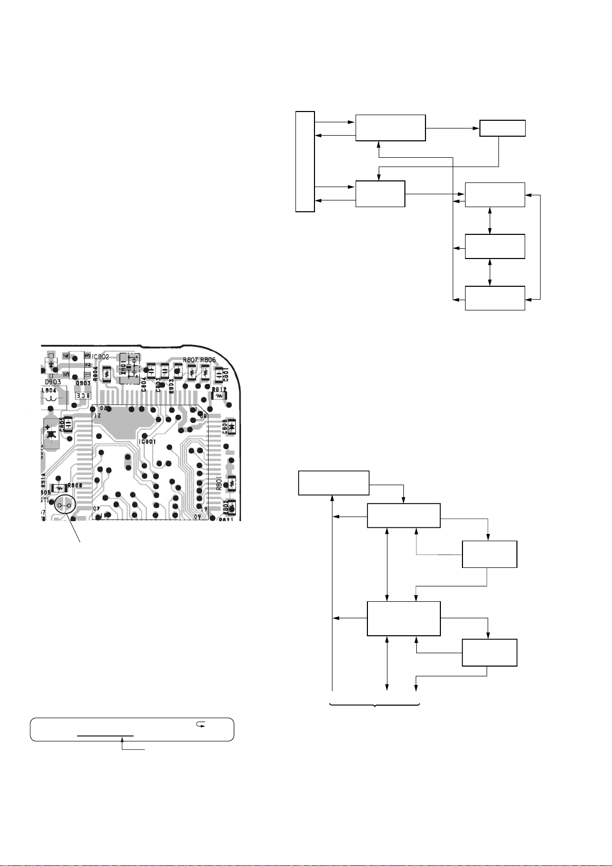
Solder bridge the test point TAP805 (TEST) on the MAIN
board (connect IC801 pin #£ to GND), and turn on the power.
– MAIN BOARD (Conductor side) –
Configuration of Test Mode
The test mode has the configuration given below.
VOL
+ key
p
key
VOL
– key
p
key
is set
Display when test mode
Displays of the LCD on the remote commander
are shown in parenthesis.
Overall
adjustment
mode (044 Auto?)
p
key
Adjustment
mode
(044 Manu?)
”/+
”
/
+
key
(044 Start?)
p
key
key
Servo mode
0 0 0
VOL
+/– keys
Audio mode
1 0 0
VOL
+/– keys
Power mode
3 0 0
Servo Mode
• Set the test mode, press the VOL – key and use the ”/+ key
to set the servo mode.
• When the servo mode is set, use the +/” key and the =
key on the set to move the optical pick-up to the outer circumference and to the inner circumference respectively.
• When entering another mode, refer to the configuration of test
mode.
VOL +/– keys
1. Structure of Servo Mode
Servo mode
0 0 0
p
Test mode
Short : Test mode
()
Open: Normal mode
”/+
Offset adjustment
key
VOL
key
0 1 0
+/– keys
p
key
Releasing the Test Mode
A test mode releasing method varies depending on the test mode
setting method.
1. When test mode was entered with key input, turn off the power .
p
key
Laser power
adjustment
0 2 0
2. When test mode was entered by shorting the test point, turn
off the power and open the solder bridge of TAP805 (TEST
MODE) on the MAIN board.
VOL
+/– keys
p
Operation of Setting on Test Mode
When the test mode is set, the LCD displays the following :
100 V1. 000
ROM version display
LCD on remote commander
SHUF
• The cycle - the above ROM version display n All lit n All
1
(See page 7.)
23
*
1 Repeatedly press ”/+ key
to change the mode.
(Refer to the following list
for a description of each
mode.)
off - is repeated.
• When the PLAYMODE key is pressed and hold down, the dis-
play at that time is held so that display can be checked.
key
”/+
”/+
key
011
key
021
to
*
1
”/+
to
*
1
014
024
”/+
key
key
– 6 –
(See page 6.)
1
p
key
p
key
p
key
p
key
p
key
p
key
23
MO adjustment
0 3 0
p
VOL
+/– keys
Low reflection
CD adjustment
0 4 0
p
VOL
+/– keys
CD adjustment
0 5 0
p
VOL
+/– keys
Sled movement
0 6 0
p
VOL
+/– keys
Automatic
adjustment
0 7 0
p
VOL
+/– keys
NV relation
0 9 0
p
VOL
+/– keys
key
key
key
key
key
key
”/+
”/+
”/+
”/+
”/+
”/+
key
031
to
03a to 03f
*
1
key
041
to
1
*
key
to
051
05a to 05f
*
1
key
061
,
1
*
key
071
to
1
*
key
to
091
*
1
039
048
”/+
059
062
”/+
074
”/+
093
”/+
key
key
key
key
2. Description of Each Mode
010 Offset adjustment
Mode Description
011 VC offset, FE offset, ABCD offset
012 Not used
013 Not used
014 Not used
020 Laser power adjustment
Mode Description
021 MO power (GRV)
022 MO power (LPIT)
023 CD power (HPIT)
024 Not used
030 MO adjustment
Mode Description
031 MO EF balance
032 MO tracking offset
033 MO ABCD gain
034 MO focus gain
035 MO tracking gain
036 MO focus bias
037
038
039
(03a)
(03b)
(03c)
(03d) Not used
(03e) Not used
(03f) Not used
040 Lower reflection CD adjustment
Mode Description
041 Lower reflection CD EF balance
042 Lower reflection CD tracking offset
043 Lower reflection CD ABCD gain
044 Lower reflection CD focus gain
045 Lower reflection CD tracking gain
046 Lower reflection CD focus bias
047
048 Not used
Retern the Offset
adjustment (
0 1 0
*
1 : Repeatedly press ”/+ key
to change the mode.
(Refer to the following list
)
for a description of each
mode.)
– 7 –
050 CD adjustment
Mode Description
051 CD EF balance
052 CD tracking offset
053 CD ABCD gain
054 CD focus gain
055 CD tracking gain
056 CD focus bias
057
058
059
(05a)
(05b)
(05c)
(05d) Not used
(05e) Not used
(05f) Nor used
060 Sled movement
Mode Description
061 Sled in
062 Sled out
Audio Mode
• Enter the test mode and press the VOL – key. Then, press the
”/+ key and the V OL + k ey in this turn to enter audio mode.
• When entering another mode, refer to the configuration of test
mode.
1. Structure of Audio Mode
”/+
1 1 0
p
key
key
”/+
key
3 kHz Beep sound
1 1 1
”/+
key
Audio mode
1 0 0
p
key
Audio playback test
070 Automatic adjustment
Mode Description
071 Focus search
072 Access 32
073 Not used
074 Not used
090 NV relation
Mode Description
091 NV clear
092 Power OFF
093 Function code change
Note: The parenthesizal mode numbers in table are not displayed on the
LCD of remote commander.
– 8 –
Power Mode
• Enter the test mode and press the VOL – ke y . Then, press the ”/
+ key and the VOL – key in this turn to enter power mode.
• When entering another mode, refer to the configuration of test
mode.
1. Structure of Power Mode
”/+
Power mode
3 0 0
p
key
key
UNREG check
31 0
p
key
”/+
Power OFF
key
3 1 1
”/+
key
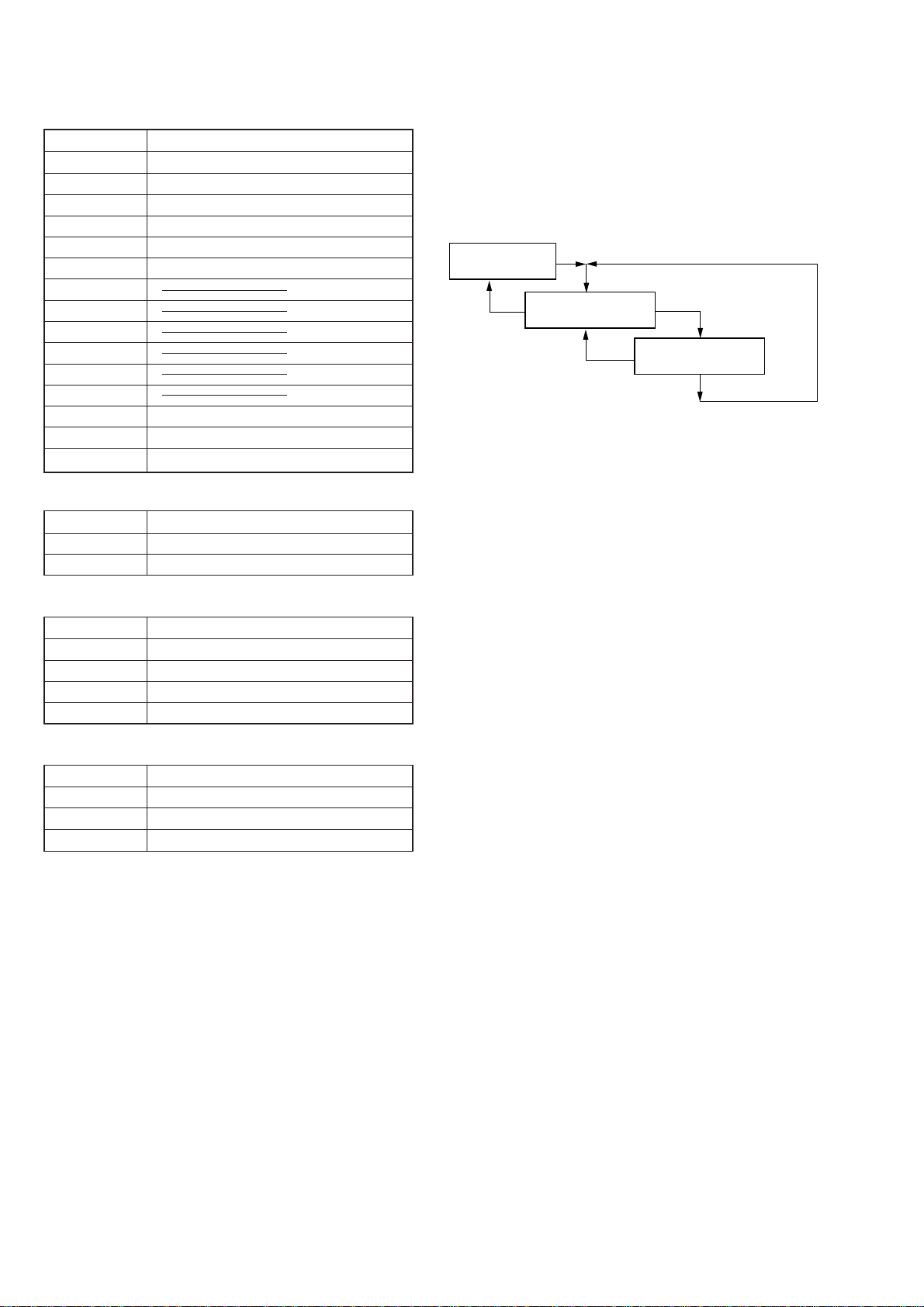
Overall Adjustment Mode
• Enter the test mode and press the VOL + key to enter overall
adjustment mode.
• When entering another mode, refer to the configuration of test
mode.
• When the overall adjustment mode is entered, the LCD on the
remote commander display the following :
044 Auto?
1. Structure of Overall Adjustment Mode
Overall
adjustment
mode
Auto?
”/+
key
Start ?
”/+
key (to discriminate between CD and MO)
CD automatic
adjustment
MO automatic
adjustment
OK
NG
OK
NG
p
key
p
key
p
key
p
key
Adjustment
mode
Manu ?
– 9 –
SECTION 5
)
ELECTRICAL ADJUSTMENTS
Notes for Adjustment
• In this set, automatic adjustment of CD and MO can be performed by entering the test mode. (See page 6)
• Adjustments are performed in the overall adjustment mode. If
an item is determined as NG, the item is readjusted in servo
mode.
Adjustment Method in Overall Adjustment Mode
1. Enter the test mode and press the VOL + key to enter overall
adjustment mode.
2. Insert the CD test disc TDYS-1 (Parts No. 4-963-646-01) or
SONY MO disc (recorded) commercially available.
3. Press the ”/+ key . The disc is determined whether it is CD
or MO and each adjustment mode is set. Automatic adjustments are performed in the order of the items listed below.
• In CD Automatic adjustment Mode
No. Mode Description
1 061 Sled in
2 062 Sled out
3 071 Focus search
4 051 CD EF balance
5 053 CD ABCD gain
6 051 CD EF balance
7 052 CD tracking offset
8 054 CD focus gain
9 055 CD tracking gain
10 056 CD focus bias
* Remote commander display during automatic adjustment
055
Adjustment value (flashing)
Mode No. under adjustment
4. If result of automatic adjustment is OK, the following display
appears.
056
5. If result of automatic adjustment is NG, the following display
appears.
052
NG mode No.
* If NG, enter servo mode to perform automatic adjustment of the
item determined as NG.
Adjustment in Servo Mode Method
1. When each adjustment mode is set according to the structure
of servo mode, the lower two digits of the mode No. and the
adjustment value written in EEPROM are displayed and lit on
the LCD on the remote commander. (See page 6)
End-OK
NG
Error code
• In MO Automatic adjustment Mode
No. Mode Description
1 061 Sled in
2 062 Sled out
3 071 Focus search
4 031 MO EF balance
5 033 MO ABCD gain
6 031 MO EF balance
7 032 MO tracking offset
8 034 MO focus gain
9 035 MO tracking gain
10 036 MO focus bias
052
Adjustment value (lit)
Mode No.
2. When the P key is pressed, the following display appears and
the automatic adjustment is performed.
052
Adjustment value (flashing)
Note: Although the VOL +/– keys can be used to change the adjust-
ment value to any value, they should not be used whenever
possible.
3. When the automatic adjustment is completed, the flashing adjustment value is lit.
052
Adjustment value (lit
– 10 –
 Loading...