

SONY MZ-E60 SERVICE MANUAL
MICROFILM
MZ-E60
SERVICE MANUAL
(Photo: Silver)
US and foreign patents licensed from Dolby
Laboratories Licensing Corporation.
SPECIFICATIONS
System
Audio playing system
MiniDisc digital audio system
Laser diode properties
Material: GaAlAs
Wavelength: λ = 790 nm
Emission duration: continuous
Laser output: less than 44.6 µW
(This output is the value measured at a distance
of 200 mm from the objective lens surface on the
optical pick-up block with 7 mm aperture.)
Revolutions
800 rpm to 1,800 rpm
Error correction
Advanced Cross Interleave Reed Solomon
Code (ACIRC)
Sampling frequency
44.1 kHz
Coding
Adaptive TRansform Acoustic Coding (ATRAC)
Modulation system
EFM (Eight to Fourteen Modulation)
Number of channels
2 stereo channels
1 monaural channel
Frequency response
20 to 20,000 Hz ± 3 dB
Wow and Flutter
Below measurable limit
Outputs
Headphones: stereo mini-jack,
maximum output level 5 mW + 5 mW, load
impedance 16 ohms
US Model
Canadian Model
AEP Model
E Model
Model Name Using Similar Mechanism MZ-E90
MD Mechanism T ype MT-MZE60-169
Optical Pick-up Mechanism Type LCX-2E
General
Power requirements
One LR6 (size AA) battery (not supplied)
Battery operation time
You can check the battery condition with the
battery indication which is displayed while using
the player.
t Battery power decreasing
v
r Weak battery
v
e The battery has gone out. “LOW BATT”
flashes in the display on the remote control,
and the power goes off.
Battery Life
Approximately 12 hours of playback can be
expected with one LR6 (size AA) alkaline battery
(not supplied).
Note
The battery life may shorter depending on
operating conditions and temperature of the
location.
– Continued on next page –
PORTABLE MINIDISC PLAYER
– 1 –
SECTION 4
TEST MODE
4-1. GENERAL
• When entered in the TEST MODE, this set provides the Overall
Adjustment mode which allows CD and MO discs to be automatically adjusted. In the Overall Adjustment mode , the system
discriminates between CD and MO discs, performs adjustments
in sequence automatically , and displays the faulty location if any
fault is found. In the Manual mode, selected adjustments can be
performed automatically.
• The attached remote control is used to operate the TEST MODE.
Unless otherwise specified in the text, the key means that on the
remote control.
4-2. SETTING THE TEST MODE
4-2-1. How to set the TEST MODE
To set the TEST MODE, two methods are available.
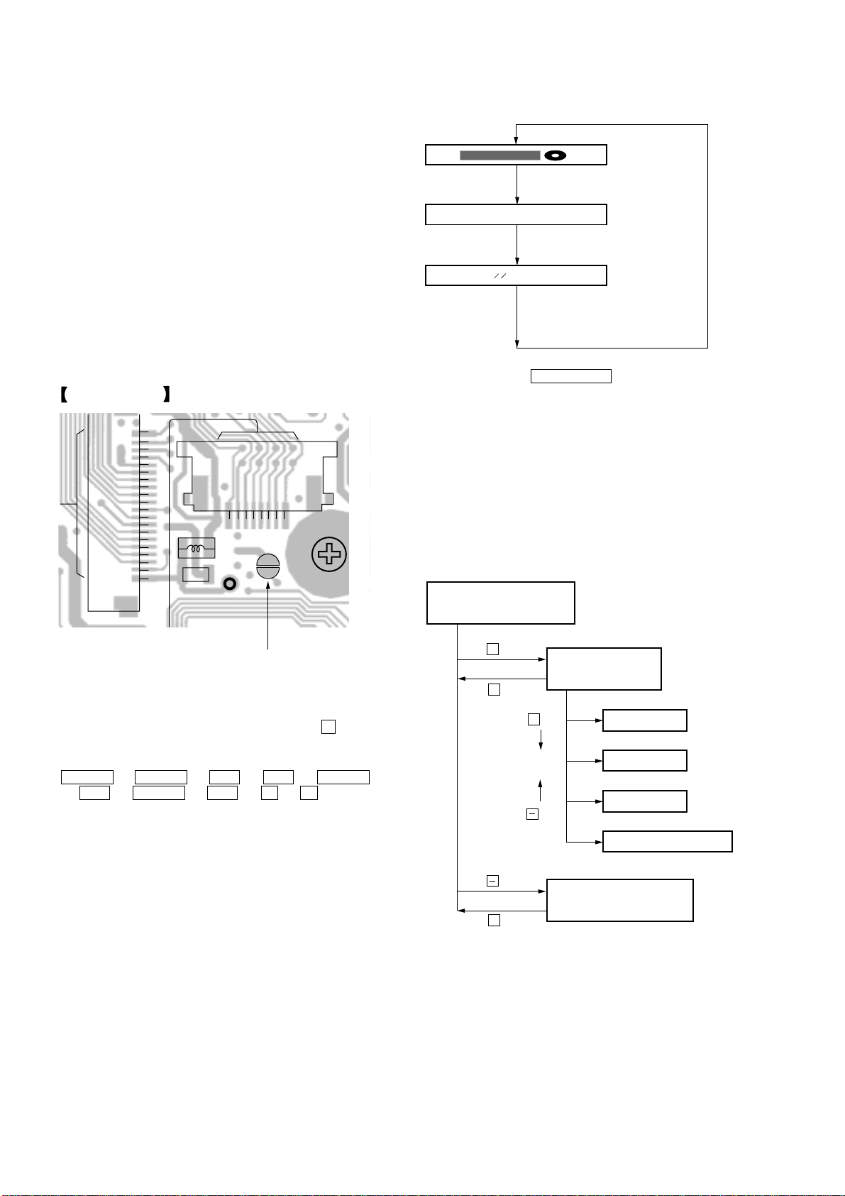
1 Solder bridge and short TAP801 (TEST) on the main board.
Then turn on the power.
MAIN BOARD (SIDE B)
1
10
CN501
15
20
5
L501
C518
CN551
815
TAP801
TP518
Remote control LCD
888
u
All on
All off
004 V1.100
Microprocessor
version
display
• Press and hold down PLAY MODE to hold the current display
while the key is being pressed.
4-2-3. How to release the TEST MODE
When method 1 was used:
Turn off the power and open the solder bridge on T AP801 on the
main board.
Note: The solder should be removed clean. The remaining
solder may make a short with the chassis and other part.
When method 2 was used:
Turn off the power.
4-3. TEST MODE STRUCTURE
Test Mode
(Display Check Mode)
TAP801
2 In the normal mode, operate the keys on the set and those on the
remote control as specified below:
Turn on HOLD switch on the set. Holding down x (STOP)
key on the set, press the keys on the remote control in the
following sequence:
> N t > N t . t . t > N
t . t > N t . t X t X
4-2-2. Operations when the TEST MODE is set
When the TEST MODE is entered, the system switches to the
display check mode within the TEST MODE. From this mode, the
other Test modes can be accessed.
When the TEST MODE is set, the LCD repeats a cycle of the
following displays:
+
key
Manual Mode
x
key
+
key
key
key
Overall Adjustment Mode
x
key
Servo Mode
Audio Mode
Power Mode
OP Alignment Mode
– 10 –
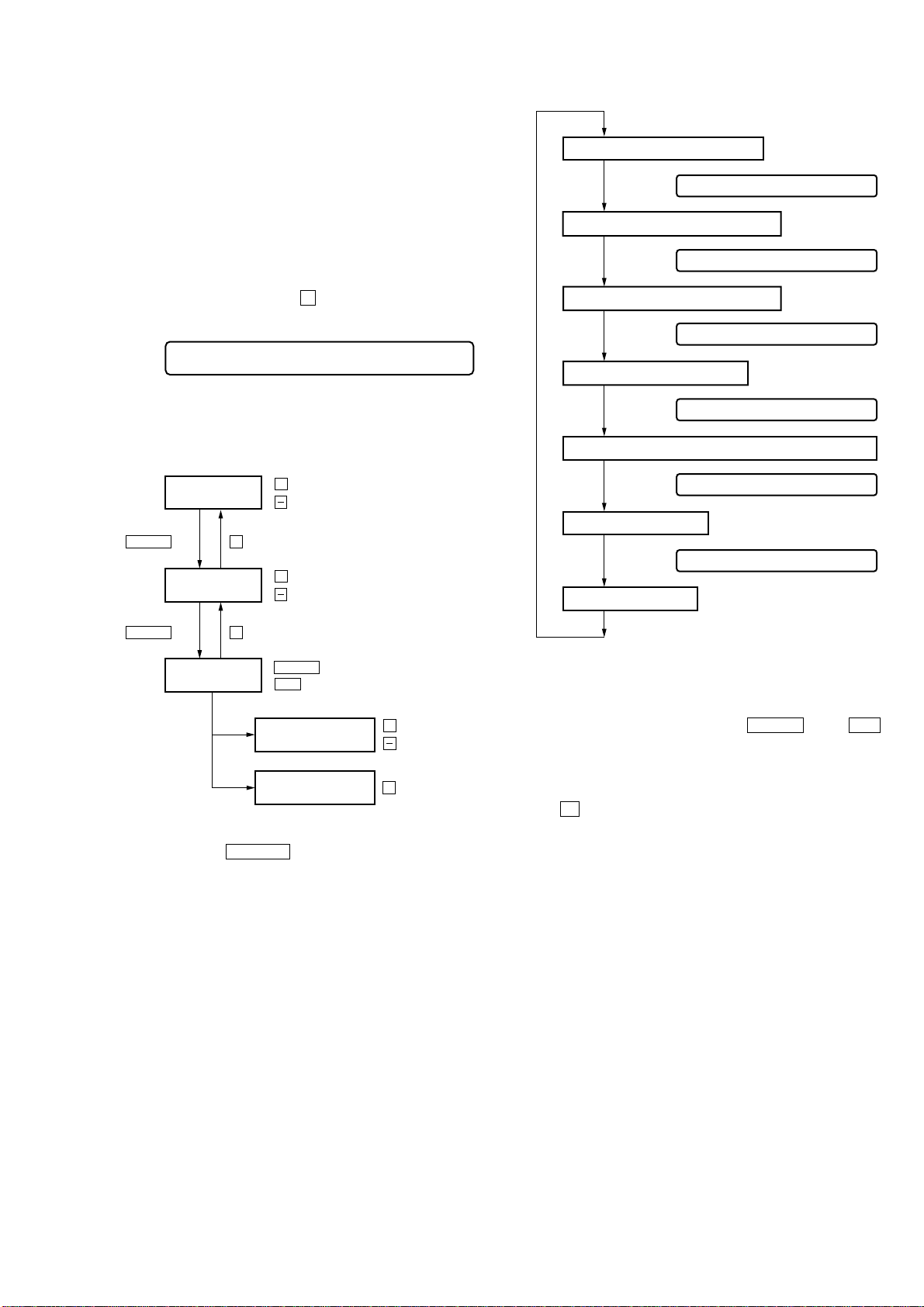
4-4. MANUAL MODE
011 XXXSXX
011 XX BXX
011 XX AXX
011 XXXJXX
011 XX RXX
731 XX VXX
Address Value & Adjustment Value
Block Error Value & Adjustment Value
ADIP Error Value & Adjustment Value
Jitter Value & Adjustment Value
Asy Mmetry Feed Back Gain Value & Adjustment Value
Power Adjustment Value
XXX: Each Value
XX: Adjustment Value
for Item number
Memory Monitor Mode
LCD display
LCD display
LCD display
LCD display
LCD display
LCD display
4-4-1. Outline of the function
The Manual mode is designed to perform adjustments and
operational checks on the set’s operation according to each
individual function.
Usually, no adjustments are made in this mode.
However, the Manual mode is used to clear the memory before
performing automatic adjustments in the Overall Adjustment mode.
4-4-2. How to set the Manual mode
1. Set the TEST MODE and press + key to set the Manual mode.
Remote control LCD display
000 AAASCC
2. Each test item is assigned with a three-digit item number. The
third digit stands for a major item, the second digit for a middle
item, and the first digit for a moniro item.
+
key : Up
key : Down
keykey
> N
Change Major
Item
x
Change Middle
Item
key
> N
Change Minor
Item
3. During each test mode, the display is changed from one to
another each time DISPLAY key is pressed.
+
key : Up
key : Down
x
key
> N
.
key : Down
Change Adjustment
Value
Write Adjustment
Value
key : Up
+
key : Up
key : Down
X
key : Write
Note: In the Power mode, the power adjustment value is only
displayed.
4. During each test, press and hold down > N key or .
key for a while to move the optical pickup on the sled outer or
inner perimeter.
5. To terminate the Manual mode and return to the TEST MODE,
press x key.
4-5. OVERALL ADJUSTMENT MODE
4-5-1. Outline of the function
This mode is designed to adjust the servo system automatically by
going through all the adjustment items.
Usually, this mode is used to perform automatic adjustments when
servicing the set.
For further information, refer to section 5. ELECTRICAL ADJUST MENTS (page 12).
– 11 –
SECTION 5
ELECTRICAL ADJUSTMENTS
5-1. GENERAL
In this set, CD and MO discs can be automatically adjusted by setting the Overall Adjustment mode within the TEST MODE,
Before performing these automatic adjustments, it is necessary to
clear the memory and adjust the power in the Manual mode.
5-2. NOTES FOR ADJUSTMENT
5-2-1. Jigs
• CD disc TDYS-1 (part code: 4-963-646-01)
• MO disc PTDM-1 (part code: J-2501-054-A)
or commercially available MO disc (recorded)
• Digital voltmeter
5-2-2. Adjustment sequence
The adjustments should be always performed in the following
sequence:
1 Reset NV (Clear the memory)
2 Overall CD adjustments
3 Overall MO adjustments
5-2-3. Power
A stablized power supply is used to supply 1.5 V DC to the battery
terminal.
Otherwise, an AA alkali battery with the remaining level of 1.5 V
DC or more is used. (In this case, make sure that the battery
indication on the remote control is “FULL”)
Manual mode
Overall adjustment mode
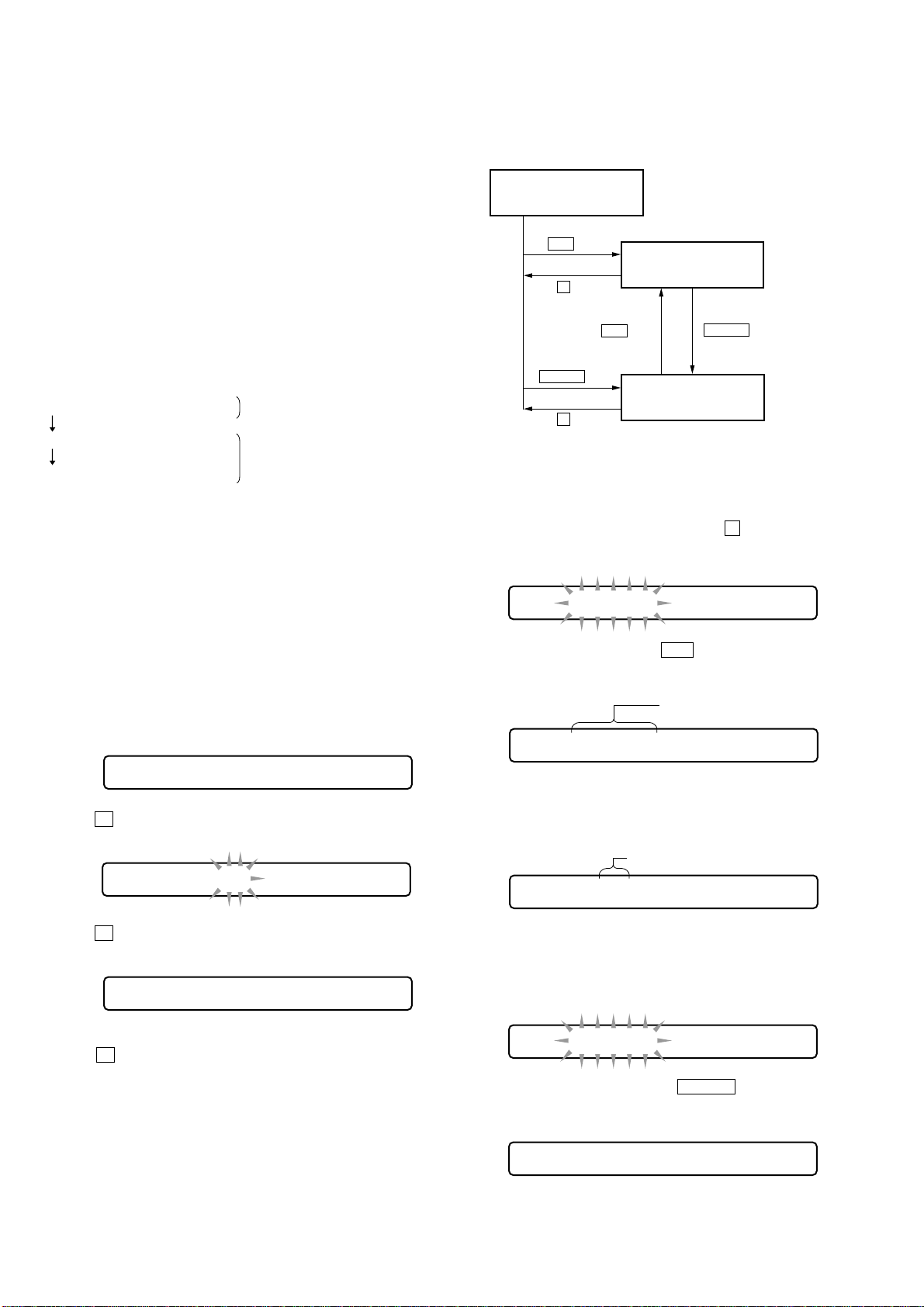
5-4. OVERALL ADJUSTMENT MODE
5-4-1. Overall adjustment mode structure
Overall Adjustment Mode
.
key
Overall CD Adjustment
x
key
.
key
key
> N
Overall MO Adjustment
x
key
Note: The overall adjustments should be always performed in the
sequence of CD t MD adjustments.
5-4-2. Overall CD and MO adjustment method
1. Set the TEST MODE (see page 10) and press – key to set the
Overall Adjustment mode.
LCD display
> N
key
044 Assy ?
5-3. RESET NV
5-3-1. How to reset NV
1. Set the TEST MODE. (See page 10)
2. Set the Manual mode and set the item No. 021, Reset NV.
LCD display
021 AAASCC
3. Press X key on the remote control.
LCD display
021 AAASCC
Note: CC is blink.
4. Press X key on the remote control again.
LCD display
021 AAASCC
Note: CC blink. t Finish the CC light on.
5. Press x key to terminate the Manual mode and return to the
TEST MODE.
2. Insert CD disc in the set, and press . key to set the Overall
CD Adjustment mode.
Automatic adjustments are made.
LCD display
Display on Adjustment state
for Each Items.
XXX XXXSXX
XXX: Item No. for which an adjustment is being executed.
3. If NG in the overall CD adjustments, return to Reset NV and
perform the adjustment again.
LCD display
Adjustment Value becomed to NG.
XXX NGXX
XXX: NG item No.
4. If OK through the overall CD adjustments, then perform overall
MO adjustments.
LCD display
XXX End-OK
5. Insert MO disc in the set, and press > N key to set the
Overall MO Adjustment mode. Automatic adjustments are made.
LCD display
– 12 –
XXX XXXSXX
XXX: Item No. for which an adjustment is being executed.
 Loading...