

Sony MZE-510 Service manual
MZ-E510
Audio playing system
MiniDisc digital audio system
Laser diode properties
Material: GaAlAs
Wavelength: λ = 790 nm
Emission duration: continuous
Laser output: less than 44.6 µW*
* This output is the value measured at a distance
of 200 mm from the objective lens surface on
the optical pick-up block with 7 mm aperture.
Revolutions
Approx. 300 rpm to 2,700 rpm
Error correction
ACIRC (Advanced Cross Interleave Reed
Solomon Code)
Sampling frequency
44.1 kHz
Coding
ATRAC (Adaptive TRansform Acoustic Coding)
ATRAC3: LP2/LP4
Modulation system
EFM (Eight to Fourteen Modulation)
Number of channels
2 stereo channels
1 monaural channel
Frequency response
20 to 20,000 Hz ± 3 dB
Outputs
Headphones/earphones: stereo mini-jack,
output level
5 mW + 5 mW load impedance 16 Ω
Power requirements
Nickel metal hydride rechargeable battery
One NH-10WM (supplied): 1.2 V,
900 mAh (MIN)
One LR6 (size AA) battery (not supplied)
External power jack (for the battery charging
stand): Power rating 3V DC
Battery operation time
Battery life
1)
(Unit: Approx. hours) (JEITA2))
Batteries
Ni-MH
rechargeable
battery
NH-10WM
3)
LR6 (SG)
Sony Alkaline
dry battery
4)
LR6 (SG)4) and
NH-10WM
3)
1)
Measured with the power save function on (see
“Preserving battery power”).
2)
Measured in accordance with the JEITA (Japan
Electronics and Information Technology
Industries Association) standard (using a Sony
MDW-series Mini-disc).
3)
With a fully charged battery
4)
When using a Sony LR6 (SG) “STAMINA”
alkaline dry battery (produced in Japan).
Note
The battery life may be shorter than that
specified, depending on the temperature of the
location, the operating conditions, and the type
of battery being used.
SP
Stereo
LP2 LP4
(normal)
Stereo Stereo
26 32 42
57 72 91
85 107 130
Dimensions
Approx. 73.4 × 80.6 × 15.3 mm (w/h/d) (3
×
3
1
/
4
× 5/8 in.)
(not including projecting parts and controls)
Mass
Approx. 67 g (2.4 oz) (the player only)
Supplied accessories
Headphones/earphones with a remote control
(1)
Battery charging stand (1)
AC power adaptor (for the supplied battery
charging stand) (1)
Rechargeable battery (1)
Rechargeable battery carrying case (1)
Dry battery case (1)
Carrying pouch (1)
US and foreign patents licensed from Dolby
Laboratories.
Design and specifications are subject to change
without notice.
SERVICE MANUAL
Ver 1.0 2001. 01
Ver 1.0 2003. 02
Photo: Silver
US and foreign patents licensed from Dolby
Laboratories.
SPECIFICATIONS
AEP Model
E Model
Model Name Using Similar Mechanism MZ-E710
Mechanism T ype MT-MZE710-183
Optical Pick-up Name ABX-1E
9-877-043-01
2003B167800-1
© 2003.02
Sony Corporation
Personal Audio Company
Published by Sony Engineering Corporation
PORTABLE MINIDISC PLAYER
1
MZ-E510
On power sources
• Use house current, LR6 (size AA) battery, or car battery.
• For use in your house: Use the AC power adaptor supplied with
this recorder. Do not use any other AC power adaptor since it
may cause the recorder to malfunction.
Polarity of the
plug
• Connect the AC power adaptor to an easily accessible AC outlet.
Should you notice an abnormality in the AC power adaptor,
disconnect it from the AC outlet immidiately.
• The recorder is not disconnected from the AC power source
(mains) as long as it is connected to the wall outlet, even if the
recorder itself has been turned off.
• If you are not going to use this recorder for a long time, be sure
to disconnect the power supply (AC power adaptor, dry battery,
or car battery cord). To remove the AC power adaptor from the
wall outlet, grasp the adaptor plug itself; never pull the cord.
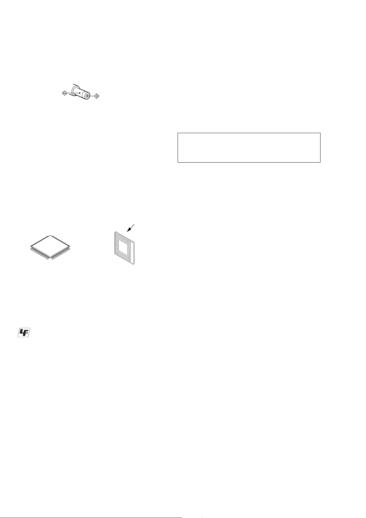
* Replacement of IC501, IC601 used in this set requires a
special tool.
• The v oltage and wav eform of CSP (chip size package) cannot be measured, because its lead layout is different from
that of conventional IC.
• Lead layouts
surface
Flexible Circuit Board Repairing
• Keep the temperature of the soldering iron around 270°C
during repairing.
• Do not touch the soldering iron on the same conductor of the
circuit board (within 3 times).
• Be careful not to apply force on the conductor when soldering
or unsoldering.
Notes on chip component replacement
• Never reuse a disconnected chip component.
• Notice that the minus side of a tantalum capacitor may be
damaged by heat.
CAUTION
Use of controls or adjustments or performance of procedures
other than those specified herein may result in hazardous
radiation exposure.
Lead layout of
conventional IC
CSP (chip size package)
Unleaded solder
Boards requiring use of unleaded solder are printed with the
lead-free mark (LF) indicating the solder contains no lead.
(Caution: Some printed circuit boards may not come printed
with the lead free mark due to their particular size.)
: LEAD FREE MARK
Unleaded solder has the following characteristics.
• Unleaded solder melts at a temperature about 40°C higher
than ordinary solder.
Ordinary soldering irons can be used but the iron tip has to be
applied to the solder joint for a slightly longer time.
Soldering irons using a temperature regulator should be set to
about 350°C.
Caution: The printed pattern (copper foil) may peel away if the
heated tip is applied for too long, so be careful!
• Strong viscosity
Unleaded solder is more viscous (sticky, less prone to flow)
than ordinary solder so use caution not to let solder bridges
occur such as on IC pins, etc.
• Usable with ordinary solder
It is best to use only unleaded solder but unleaded solder may
also be added to ordinary solder.
SAFETY-RELATED COMPONENT WARNING!!
COMPONENTS IDENTIFIED BY MARK 0 OR DO TTED LINE
WITH MARK 0 ON THE SCHEMATIC DIAGRAMS AND IN
THE PARTS LIST ARE CRITICAL TO SAFE OPERATION.
REPLACE THESE COMPONENTS WITH SONY P ARTS WHOSE
PART NUMBERS APPEAR AS SHOWN IN THIS MANUAL
OR IN SUPPLEMENTS PUBLISHED BY SONY.
2

TABLE OF CONTENTS
1. SERVICING NOTE ......................................................... 4
2. GENERAL.........................................................................5
3. DISASSEMBLY
3-1. Upper Panel, Holder Assy ............................................. 6
3-2. Mechanism Deck (MT-MZE710-183)...........................7
3-3. MAIN Board, Bracket (L) Assy, Bracket (R) Assy ....... 7
3-4. OP Service Assy (ABX-1E) .......................................... 8
4. TEST MODE ..............................................................9
5. ELECTRICAL ADJUSTMENTS............................. 14
6. DIAGRAMS
6-1. Block Diagrams ........................................................... 27
6-2. Printed Wiring Boards - MAIN Board (Side A) -........ 28
6-3. Printed Wiring Boards - MAIN Board (Side B) - ........29
6-4. Schematic Diagrams - MAIN Board (1/4) - ................ 30
6-5. Schematic Diagrams - MAIN Board (2/4) - ................ 31
6-6. Schematic Diagrams - MAIN Board (3/4) - ................ 32
6-7. Schematic Diagrams - MAIN Board (4/4) - ................ 33
6-8. IC Block Diagrams ...................................................... 34
6-9. IC Pin Function Description ........................................ 36
MZ-E510
7. EXPLODED VIEWS
7-1. Case Section ................................................................ 40
7-2. Mechanism Deck Section (MT-MZE710-183)............41
8. ELECTRICAL PARTS LIST...................................... 42
3
MZ-E510
SECTION 1
SERVICING NOTE
NOTES ON HANDLING THE OPTICAL PICK-UP
BLOCK OR BASE UNIT
The laser diode in the optical pick-up block may suffer electrostatic break-down because of the potential difference generated
by the charged electrostatic load, etc. on clothing and the human
body.
During repair, pay attention to electrostatic break-down and also
use the procedure in the printed matter which is included in the
repair parts.
The flexible board is easily damaged and should be handled with
care.
NOTES ON LASER DIODE EMISSION CHECK
Never look into the laser diode emission from right above when
checking it for adjustment. It is feared that you will lose your sight.
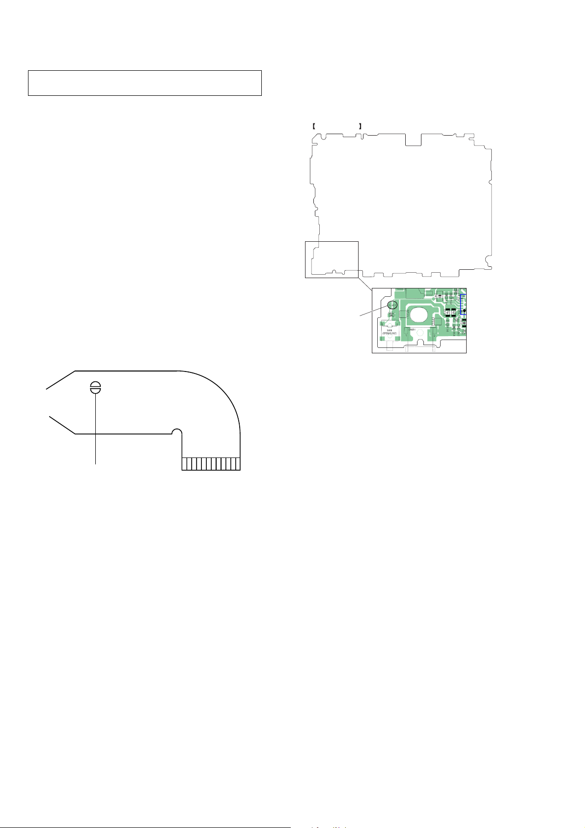
NOTES ON HANDLING THE OPTICAL PICK-UP BLOCK
(ABX-1E)
The laser diode in the optical pick-up block may suffer electrostatic break-down easily. When handling it, perform soldering
bridge to the laser-tap on the flexible board. Also perform measures against electrostatic break-down sufficiently before the operation. The flexible board is easily damaged and should be handled
with care.
• In performing the repair the power supplied to the set, removing the MAIN board causes the set to be disabled.
In such a case, perform soldering bridge to SL602 on the MAIN
board.
MAIN BOARD (SIDE A)
SL602
laser-tap
OPTICAL PICK-UP FLEXIBLE BOARD
4
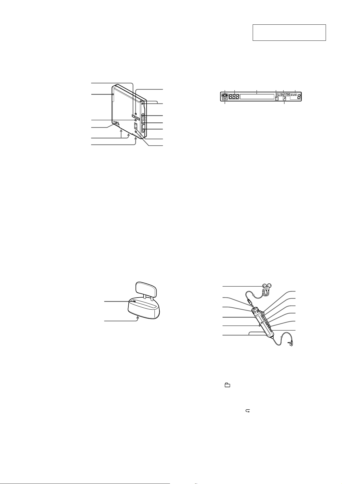
The Player
2
3
1
4
5
8
7
9
q;
qa
qs
qd
6
1 VOLUME +*, – buttons
2 Battery compartment
3
u*
button
4 HOLD (Locking the control) switch
5 Terminals for dry battery case (at the
bottom)
6 Terminals for charging stand (at the
bottom)
7 GROUP button
8 Hand strap hole
Use the hole to attach your strap.
9 i (headphones/earphones) jack
q; “3-color info-LED”
qa OPEN switch
qs .,
>
button
qd x
button
* VOLUME + and u have a tactile dot.
The display window of the remote
control
12 3 45 6
78
1 Disc indication
2 Track number display
3 Character information display
4 Group play indication
5 Play mode indication
6 6-band equalizer indications
7 Battery level indication
8 Bookmark indication
The battery charging stand
B
A
1 Terminals for charging
2 DC IN 3V jack (at the bottom)
The headphones/earphones with a
remote control
8
9
qa
qs
7
A
B
C
D
5
F
q;
1 Headphones/earphones
2 Stereo mini plug
3 Control VOL +, –
Turn to adjust the volume.
4 x (stop) button
5 Jog lever (.•
u
/ENT•>) button
6
(Group) +, – button
7 Clip
8 HOLD switch
9 Display window
q; DISPLAY button
qa P MODE /
(play mode/repeat) button
qs SOUND button
Parts and controls
SECTION 2
GENERAL
MZ-E510
This section is extracted from
instruction manual.
5
MZ-E510
)
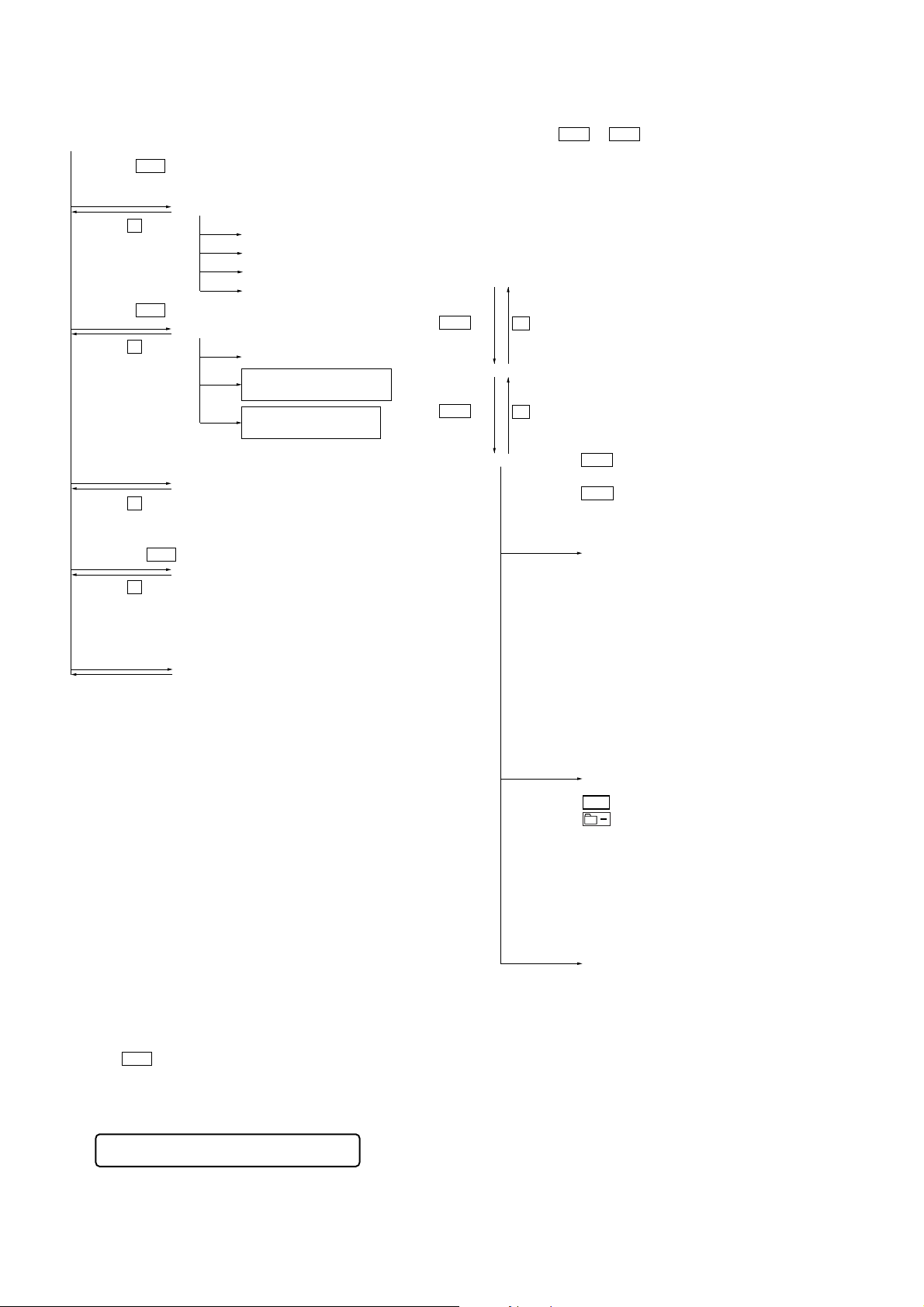
SECTION 3
DISASSEMBLY
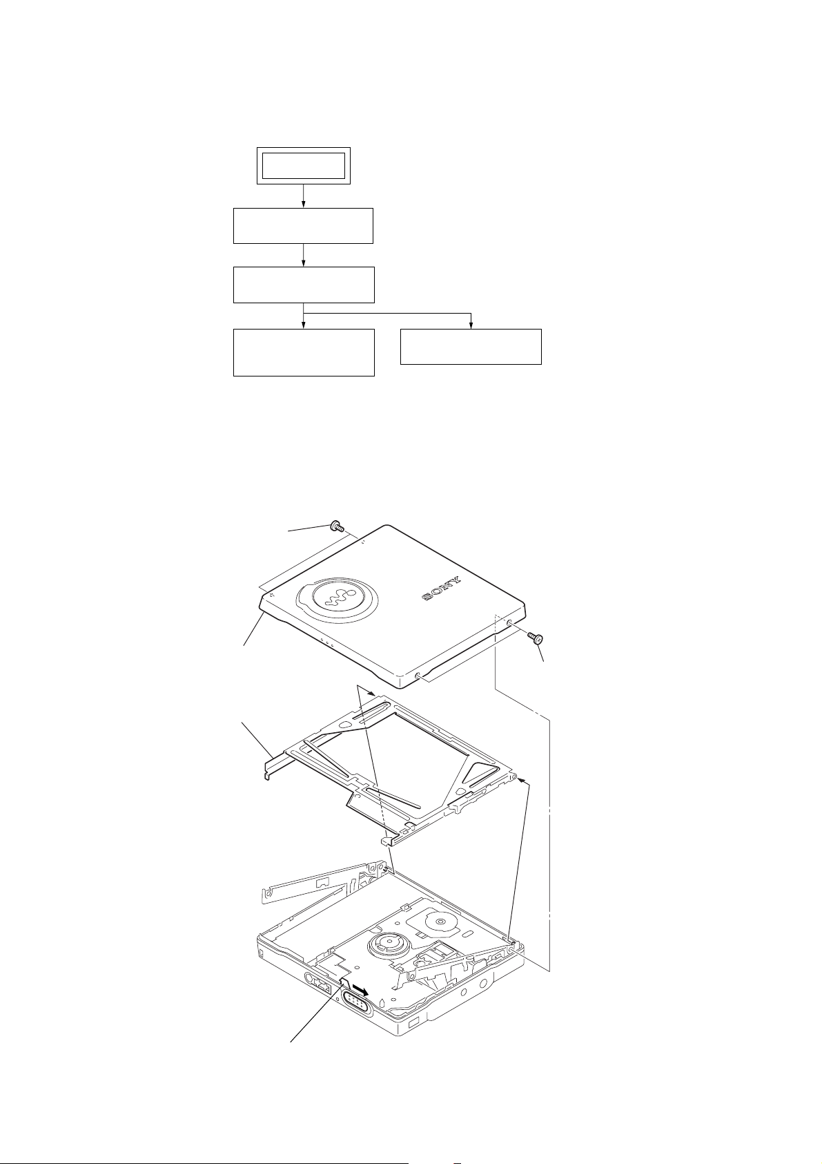
Note :This set can be disassemble according to the following sequence.
SET
UPPER PANEL,
HOLDER ASSY
MECHANISM DECK
(MT-MZE710-183)
MAIN BOARD,
BRACKET (L) ASSY,
BRACKET (R) ASSY
Note : Follow the disassembly procedure in the numerical order given.
3-1. Upper Panel, Holder Assy
3 two screws (M1.4)
4 upper panel assy
5 holder assy
OP SERVICE ASSY
(ABX-1E)
2 two screws (M1.4
1 Slide the open slider in the direction of the arrow,
and open the upper panel section.
6
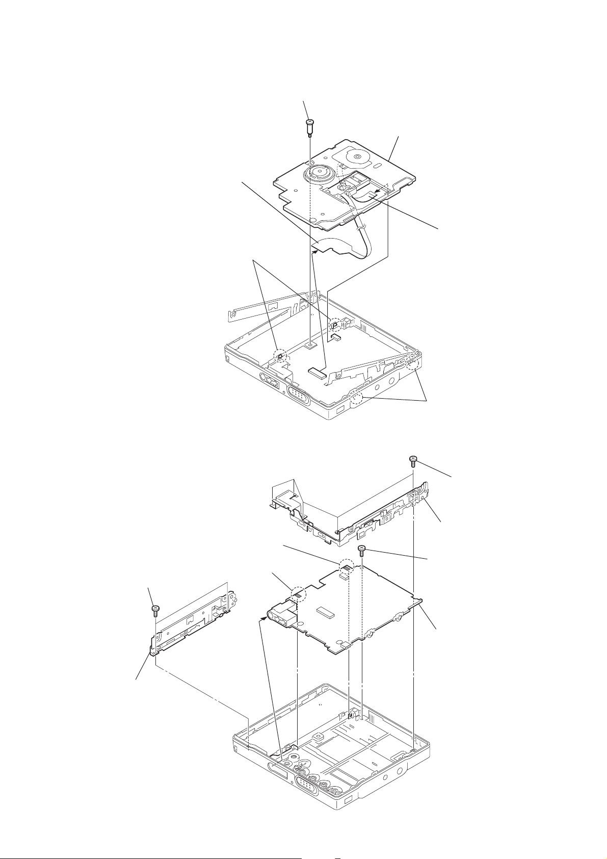
3-2. Mechanism Deck (MT-MZE710-183)
)
1
five tapping screws (M1.7)
5
tapping screw (M1.7)
7
two tapping screws (M1.7)
2
bracket (R) assy
8
bracket (L) assy
6
MAIN board
3
Remove the solder of
terminal (plus).
4
Remove the solder of
terminal (minus).
4
flexible board (optical pick-up)
(CN501)
3
two claws
1
step screw (1.7)
6
mechanism deck
(MT-MZE710-183)
5
flexible board (motor
(CN551)
MZ-E510
3-3. MAIN Board, Bracket (L) Assy, Bracket (R) Assy
2
two claws
7
MZ-E510
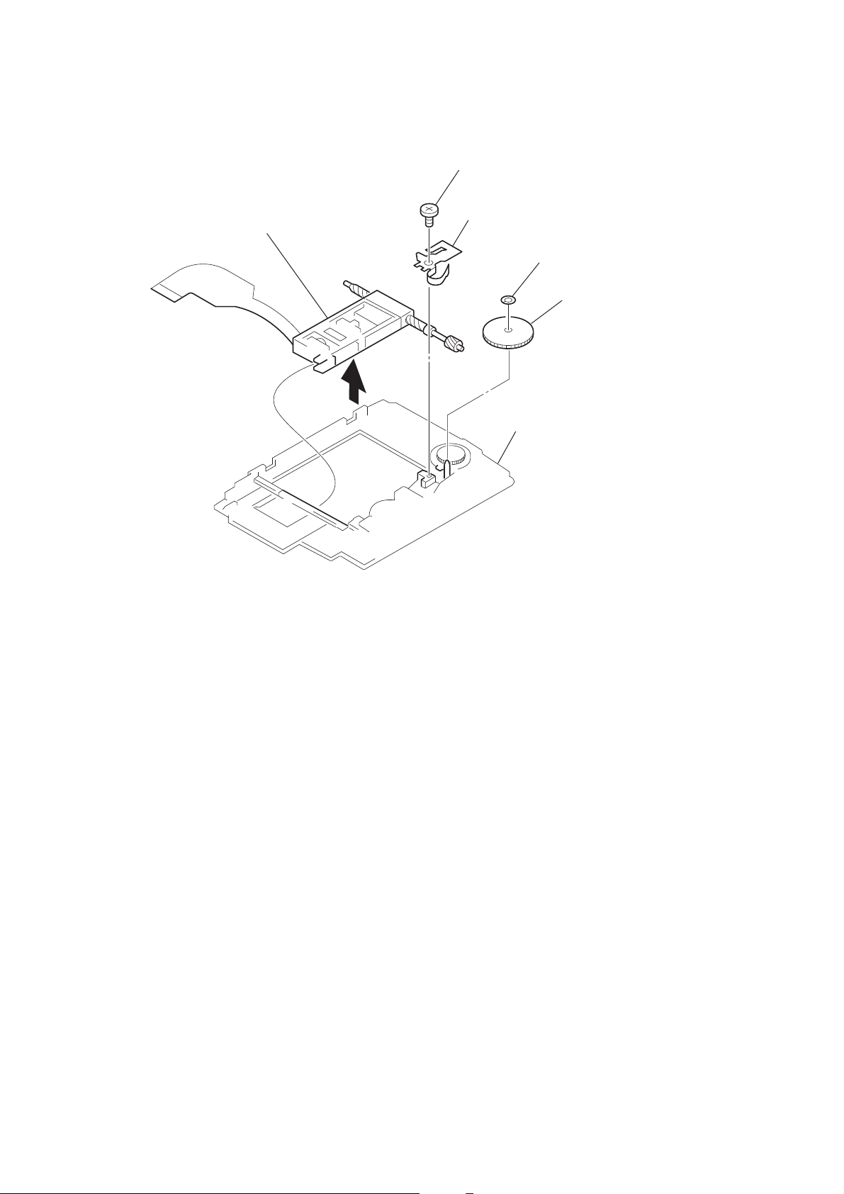
3-4. OP Service Assy (ABX-1E)
6
OP service assy (ABX-1E)
5
3
screw, self tap
4
spring, thrust retainer
1
chassis
washer (0.8-2.5)
2
gear (SSA)
8
SECTION 4
TEST MODE
MZ-E510
Outline
•This set provides the Overall adjustment mode that allows CD
and MO discs to be automatically adjusted when in the test mode.
In this overall adjustment mode, the disc is discriminate between
CD and MO, and each adjustment is automatically executed in
order. If a fault is found , the system displays its location. Also,
the manual mode allows each individual adjustment to be automatically adjusted.
• Operation in the test mode is performed with the set. A key
having no particular description in the text, indicates a set key.
Setting Method of Test Mode
There are two different methods to set the test mode:
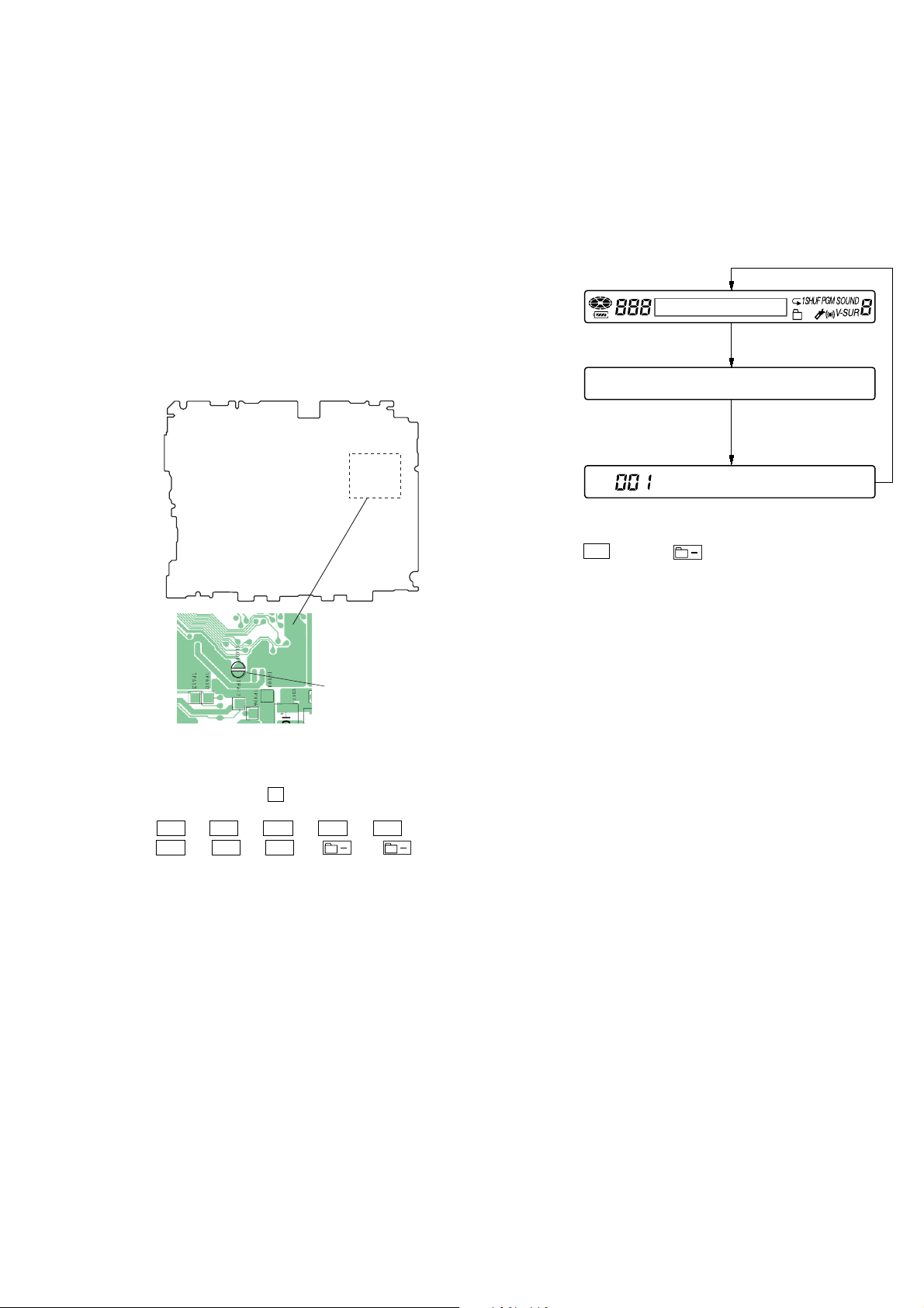
1 Short SL601 (TEST) on the MAIN board with a solder bridge
and turn on the power .
-MAIN Board (Side A)-
Operation in Setting the Test Mode
•When the test mode becomes active, first the display check mode
is selected.
• Other mode can be selected from the display check mode.
•When the test mode is set, the LCD repeats the following display.
Remote commander LCD display
All lit
All off
Microcomputer
version
display
• 3-color info LED blinks in orange.
• When the u key or the
is pressed and hold down, the display at that time is held so that
display can be checked.
V1.000
key on the remote commander
SL601 (TEST)
2 In case of setting the test mode by keys on the set and
remote commander:
In the normal mode, turn on the [HOLD] switch on the set.
While pressing the x key on the set, press the keys on the
remote commander with the following order:
> t > t . t . t > t
. t > t . t
Note: If electrical adjustment (CD and MO overall adjustment) has not
been finished completely, “ERROR” is displayed on LCDs of the
set and the remote commander.
t
Releasing the Test Mode
For test mode set with the method 1:
Turn off the power and open the solder bridge on SL601 (TEST)
on the MAIN board.
Note: Remove the solders completely. Remaining could be shorted with
the chassis, etc.
For test mode set with the method 2:
Turn off the power.
9
MZ-E510
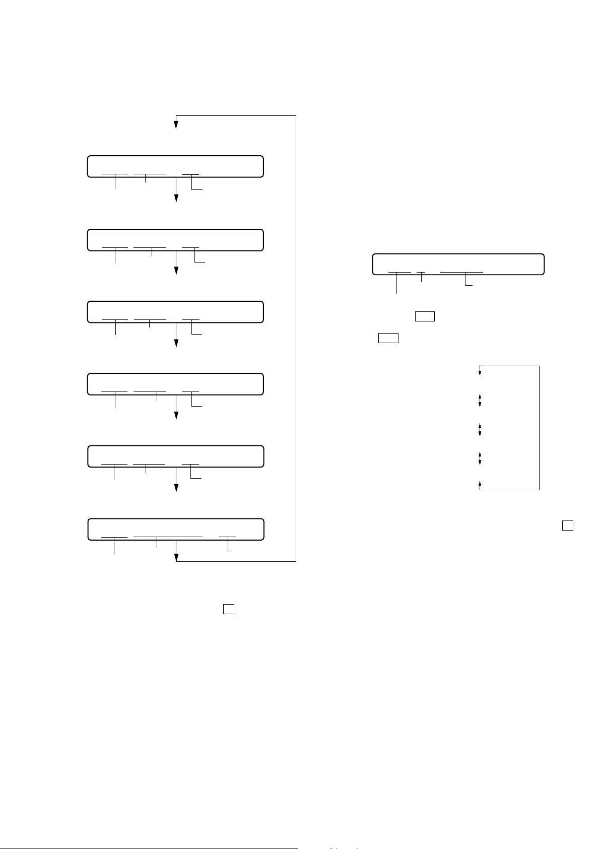
Configuration of Test Mode
[Test Mode $Display Check Mode%]
Press the
or press the
> key,
[VOL +] key on the remote commander
[Manual Mode]
Press the x key
[Servo Adjustment]
[Audio Adjustment]
[Power Supply Adjustment]
[OP Alignment Adjustment]
Press the . or [VOL --] key
[Overall Adjustment Mode]
Press the x key
Press the [GROUP] key ,
or press the [DISPLAY] key on the remote commander
[Electrical Offset Adjustment]
Power Supply Adjustment
Auto Item Feed
CD Overall Adjustment/
MO Overall Adjustment
[Self-Diagnosis Result Display Mode]
Press the x key
Press the [VOL +] key,
or press the > key on the remote commander
[Sound Skip Check Result Display Mode]
Press the x key
Press the
on the remote commander for several
seconds (about 3 seconds)
[VOL -] key, or press the [DISPLAY] key
[Key Check Mode]
The key check quits, or open the upper panel
Manual Mode
Mode to adjust or check the operation of the set by function.
Normally, the adjustment in this mode is not executed.
However, the Manual mode is used to clear the memory, power
supply adjustment, and laser power check before performing
automatic adjustments in the Overall Adjustment mode.
The manual mode consists of a major item, a medium item and a
minor item.
The manual mode is divided into four groups of major items.
SERVO : item number 000 - 500, 800 AUDIO : item number 600 POWER : item number 700 OP : item number 900 A medium item divides a major item and is used to select functions.
In a minor item, adjustments or operation checks are performed.
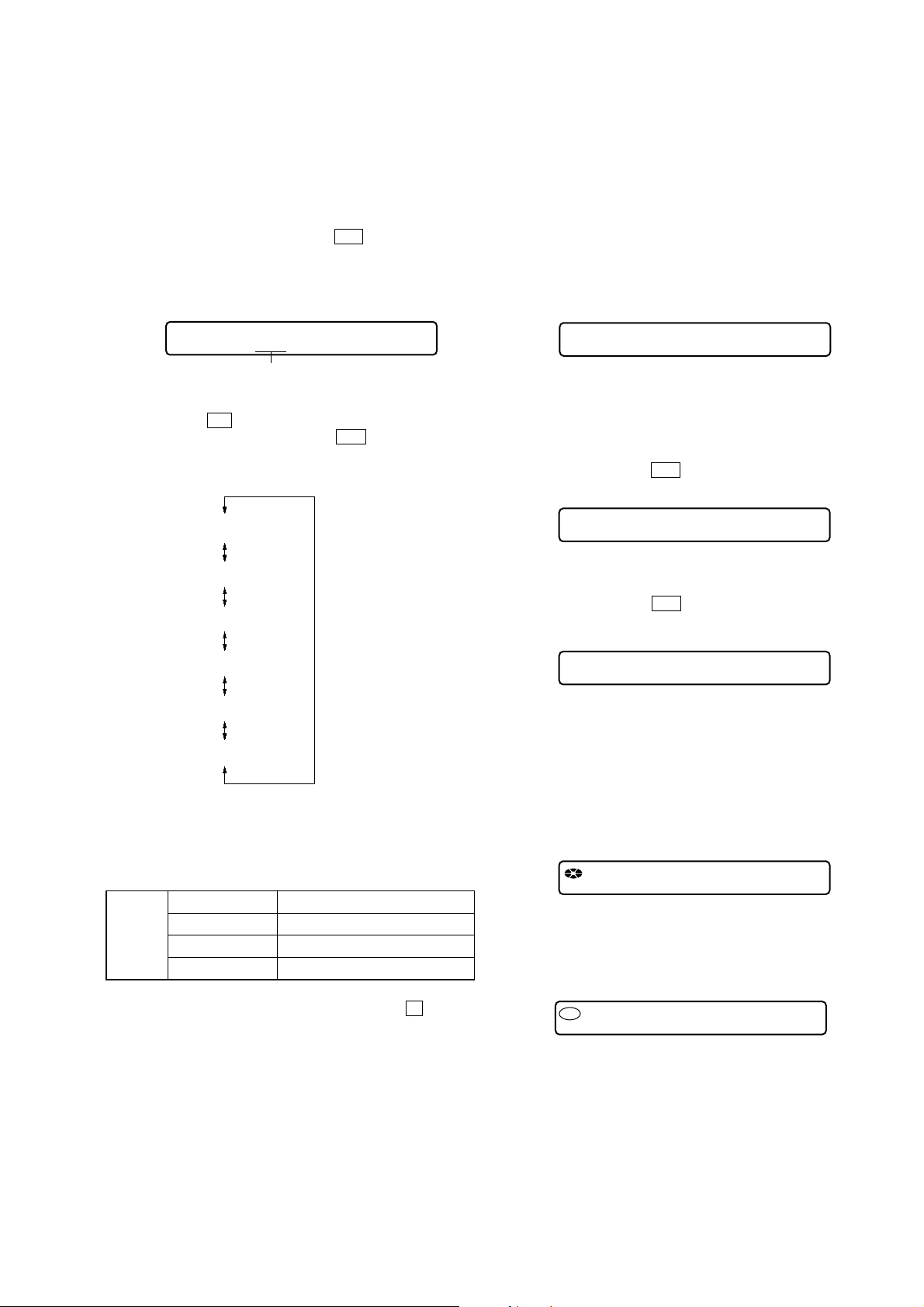
•Transition method in manual mode
1. Set the test mode (see page 9).
2. Press the > key or [VOL +] key on the remote commander
activates the manual mode where the LCD display as shown
below.
3. During each test, the optical pick-up moves outward or inward while the > or . key is pressed for several seconds respectively.
4. Each test item is assigned with a 3-digit item number;
100th place is a major item, 10th place is a medium item, and
unit place is a minor item.
The values adjusted in the test mode are written to the nonvolatile memory (for the items where adjustment was made).
[Major item switching]
x
>
key
key
[Medium item switching]
x
>
key
key
[Minor item switching]
[VOL +]
[VOL --]
[VOL +]
[VOL --]
key: 100th place of item
number increase.
key: 100th place of item
number decrease.
key: 10th place of item
number increase.
key: 10th place of item
number decrease.
>
key: Unit place of item number
increase.
.
key:Unit place of item number
decrease.
[Adjusted value variation]
[VOL +]
[VOL --]
[P MODE]
[SOUND]
key: Increases the adjusted
value of the 1st digit
key: Decreases the adjusted
value of the 1st digit
key of
the remote commander:
Increase the adjusted value
of the 2nd digit
key of the remote commander:
Decrease the adjusted value
of the 2nd digit
[Adjusted value write]
u
key or
key of the remote commander:
When adjusted value is
changed:
Adjusted value is written.
When adjusted value is
not changed:
That item is adjusted
automatically.
[RAM monitor]
[GROUP]
[DISPLAY]
for several seconds
key or
key of the remote commander
10
Remote commander LCD display
000
Manual
MZ-E510
5. The display changes a shown below each time the
PLAY] key on the remote commander is pressed.
• Address & Adjusted Value Display
Remote commander LCD display
011
C68S01
item number
• Jitter Value & Adjusted Value Display
Remote commander LCD display
011
item number
• Block Error Value & Adjusted Value Display
Remote commander LCD display
011
item number
• ADIP Error Value & Adjusted Value Display
Remote commander LCD display
address
OFFJ01
jitter value
063B01
block error
value
adjusted value
adjusted value
adjusted value
[DIS-
Self-Diagnosis Result Display Mode
This set uses the self-diagnostic function system in which if an
error occurred during the playing, the mechanism control block
and the power supply control block in the microcomputer detect it
and record its cause as history in the nonvolatile memory.
By checking this history in the test mode, you can analyze a fault
and determine its location.
• Self-diagnosis result display mode setting method
1. Set the test mode (see page 9).
2. In the display check mode, pressing the [GROUP] key or pressing the [DISPLAY] key on the remote commander activates
the self-diagnosis result display mode where the LCD display
as shown below.
Remote commander LCD display
0XX
1 ----
history code
error display code
3. Then, each time the > key is pressed, LCD display descends
by one as shown below. Also, the LCD display ascends by one
when the . key is pressed.
simple display
1
011
059A01
ADIP error
item number
• Focus Drive Value & Adjusted Value Display
Remote commander LCD display
011
item number
• Item Title Display
Remote commander LCD display
011
item number
However in the power mode (item number 700’s), only the
item is displayed.
6. Quit the manual mode, and press the
test mode (display check mode).
Overall Adjustment Mode
Mode to adjust the servo automatically in all items.
Normally, automatic adjustment is executed in this mode at the
repair.
For further information, refer to “SECTION 5 ELECTRICAL
ADJUSTMENTS” (see page 14).
value
015F01
Focus drive
value
LrefPw 01
item title
adjusted value
adjusted value
adjusted value
x key to return to the
0XX 1 ****
0XX N ****
0XX N1****
0XX N2****
XX
: Error code
****
: simple display
4. Quit the self-diagnosis result display mode, and press the
key to return to the test mode (display check mode).
1
x
11

MZ-E510
• Description of error indication codes
Problem Indication code Meaning of code Simple display Description
No error 00 No error ---- No error
01
Servo system error 02 High temperature Temp High temperature detected
03 Focus error Fcus Disordered focus or can not read an address
04 Spindle error Spdl Abnormal rotation of disc
11 TOC error TOC Faulty TOC contents
TOC error 12 Data reading error Data Data could not be read at SYNC
13 TOC address error Tadr TOC address data error
Power supply system error 22 Low battery LBat Momentary interruption detected
31 Offset error Ofst Offset error
32
Offset system error Offset error
33
34
35
36 Mirror error Mirr Mirror decision retry over
Illegal access target
address was specified
Focus error ABCD
offset error
Tracking error
X1 tracking error
Offset error
MD DATA 2
Disc error
Adrs Attempt to access an abnormal address
ABCD Focus error ABCD offset error
TE Tracking error Offset error
X1TE X1 tracking error Offset error
MD2 MD DATA 2 disc error
• Description of indication history
History code number Description
1The first error
N The last error
N1 One error before the last.
N2 Two errors before the last.
Reset the Error Display Code
After servicing, reset the error display code.
• Setting method of reset the error display code
1. Set the test mode (see page 9).
2. Pressing the [GROUP] key or pressing the [DISPLAY] key on
the remote commander activates the self-diagnosis result display mode.
3. T o reset the error display code, press the u key or
on the remote commander (twice) when the code is displayed.
Remote commander LCD display
(Key pressing at the first time)
000
ClrOK?
Remote commander LCD display
(Key pressing at the second time)
key
000
ErrCLR
(All the data on the 1, N, N1, and N2 will be reset)
12
MZ-E510
)
Sound Skip Check Result Display Mode
This set can display the count of errors that occurred during the
playing for checking.
• Setting method of sound skip check result display
mode
1. Set the test mode (see page 9).
2. Press the [VOL+] key or press the > key on the remote
commander, and then the playing sound skip check result display mode becomes active where the LCD displays the following.
Remote commander LCD display
000
P**
Total count of play
system errors (hex.)
3.
Each time the
by one as shown below. Also, if the
display item moves up by one.
Playing sound skip
result display
>
key is pressed, the display item moves do wn
.
key is pressed, the
000 P**R**
000 EIB **
000 Stat**
Key Check Mode
This set can check if the set and remote commander function normally.
• Setting method of key check mode
1. Set the test mode (see page 9).
2. Pressing the [VOL-] key or [DISPLAY] key on the remote commander for several seconds (about 3 seconds) activates the key
check mode. (At the last two digits, AD value of remote commander key line is displayed in hexadecimal)
3-color info-LED light in red.
Remote commander LCD display
000
**
**: AD value of the remote commander key
(hexadecimal 00 to FF)
3. When each key on the set and on remote commander is pressed,
its name is displayed on the remote commander LCD.
Example1: When the > key on the set is pressed:
Remote commander LCD display
000
FF **
**: AD value of the remote commander key
(hexadecimal 00 to FF)
Example2: When the > key on the remote commander is
pressed:
Remote commander LCD display
000 Adrs**
000 BEmp**
000 ######
P** : Total play errors (hex.)
** : Counter of sound skip check each item (hex.)
######: 6-digit address where sound was skipped last (hex.
• Cause of sound skip error
Cause of error Description of error
EIB Sound error correction error
Play
4. To quit the sound skip check result display mode and to return
to the test mode (display check mode), press the
Stat Decoder status error
Adrs Address access error
BEmp Buffer is empty
x key.
000
rFF **
**: AD value of the remote commander key
(hexadecimal 00 to FF)
4. When all the keys on the set or on the remote commander are
considered as OK, the following displays are shown for and 3color info-LED light in green.
Example1: When the keys on the set are considered as OK:
Remote commander LCD display
888
SET OK **
**: AD value of the remote commander key
(hexadecimal 00 to FF)
Example2: When the keys on the remote commander are con-
sidered as OK:
Remote commander LCD display
888
RMC OK **
**: AD value of the remote commander key
(hexadecimal 00 to FF)
5. When all keys were checked or if the upper panel is opened,
the key check mode quits and the test mode (display check
mode) comes back and 3-color info-LED returns to blinking
in orange.
13

MZ-E510
SECTION 5
ELECTRICAL ADJUSTMENTS
Outline
• In this set, automatic adjustment of CD and MO can be performed by entering the test mode.
However, before starting automatic adjustment, the memory
clear, power supply adjustment, and laser power check must be
performed in the manual mode.
•A key having no particular description in the text, indicates a
set key.
Precautions for Adjustment
1. Adjustment must be done in the test mode only.
After adjusting, release the test mode.
2. Use the following tools and measuring instruments.
•Test CD disc TDYS-1
(Part No. : 4-963-646-01)
• SONY MO disc available on the market
• Digital voltmeter
• Laser power meter LPM-8001
(Part No. : J-2501-046-A)
•AC adaptor (3V) and cradle
•Regulated dc power supply
•Thermometer (using the Temperature Correction)
3. Unless specified otherwise, use regulated dc power supply
(3V).
4. Switch position
HOLD switch ............................................... ON
Adjustment Sequence
1. NV Reset (item number: 021)
(EEPROM clear)
r
2. Temperature Correction (item number: 015)
r
3. Power Supply Manual Adjustment
r
4. Laser Power Check and Adjustment
r
5. CD Overall Adjustment (item number: 031)
r
MO
Overall Adjustment (item number: 032)
6.
r
7. RESUME Clear (item number 043)
r
8. Rewriting the Patch Data
(at replacement of the MAIN board)
r
9. Rewriting the NV values
Note:
“2. T emperature Correction” and “3. Power Supply Manual Adjustment” can be performed continuously with pressing the
key or the
adjustment mode.
[P MODE]
key on the remote commander in the overall
Manual Mode
Overall Mode
Manual Mode
[VOL --]
NV Reset
Caution: The shipment data will be cleared without the adjusted
values of the electrical offset adjustment and po wer supply adjustment when the NV is reset.
• Setting method of NV reset
1. Select the manual mode of the test mode, and set item number
021 NV Reset (see page 10).
Remote commander LCD display
021
ResNV CC
2. Press the
Remote commander LCD display
3. Press the
more.
Remote commander LCD display
4. Press the x key to quit the manual mode, and return to the
test mode (display check mode).
u key or
021
u key or
021
021
key on the remote commander.
ResOK?
key on the remote commander once
Res***
NV reset (after several seconds)
Reset!
Temperature Correction
• Adjustment method of temperature correction
1. Select the manual mode of test mode, and set the item number
015 (see page 10).
Remote commander LCD display
015
SetTmp#**
**
: Adjusted value
2. Measure the ambient temperature.
3. Adjust with [VOL +], [VOL --] key so that the adjusted value
(hexadecimal value) becomes the ambient temperature.
(Initial value: 19h = 25 °C, Adjusting range: 80h to 7fh
(–128 °C to +127 °C)
4. Press the u key to write the adjusted value.
5. Press the x key to quit the manual mode, and return to the
test mode (display check mode).
Note :Power supply adjustment auto item feed mode (see page 18
) is available to perform the temperature correction and
power supply adjustment without entering the manual mode.
14
 Loading...