

Sony MZB-100 Service manual
MZ-B100
SERVICE MANUAL
Ver 1.3 2004.09
With SUPPLEMENT-1
US and foreign patents licensed from Dolby
Laboratories Licensing Corporation
SPECIFICATIONS
US Model
Canadian Model
AEP Model
Tourist Model
Model Name Using Similar Mechanism NEW
Mechanism Type MT-MZB100-171
Optical Pick-up Name LCX-4R
System
Audio playing system
MiniDisc digital audio system
Laser diode properties
Material: GaAlAs
Wavelength: λ = 790 nm
Emission duration: continuous
Laser output: less than 44.6 µW
(This output is the value measured at a distance
of 200 mm from the lens surface on the optical
pick-up block with 7 mm aperture.)
Recording and playback time
When using MDW-80
Maximum 160 min. in monaural.
Maximum 320 min. in stereo
Revolutions
About 350 rpm to 2,800 rpm (CLV)
Error correction
ACIRC (Advanced Cross Interleave Reed
Solomon Code)
Sampling frequency
44.1 kHz
Sampling rate converter
Input: 32 kHz/44.1 kHz/48 kHz
Coding
ATRAC (Adaptive TRansform Acoustic
Coding)
ATRAC3 — LP2/LP4
Modulation system
EFM (Eight to Fourteen Modulation)
Speaker
28 mm (1 1/8 in.) dia.
Frequency response (digital/analog input)
20 to 20,000 Hz ± 3 dB
Wow and Flutter
Below measurable limit
Inputs
Microphone: stereo mini-jack
(minimum input level 0.25 mV)
Line in1):
stereo mini-jack for analog input
(minimum input level 39 mV)
optical (digital) mini-jack for optical
(digital) input
Outputs
i : stereo mini-jack (dedicated remote control
jack)
Maximum output (DC)
Headphones: 5 mW + 5 mW (16 ohm)
Speaker: 70 mW
2)
– Continued on next page –
9-873-341-04
2004I02-1
© 2004.09
PORTABLE MINIDISC RECORDER
Sony Corporation
Personal Audio Company
Published by Sony Engineering Corporation

MZ-B100
Ver 1.1 2002.03
General
Power requirements
DC 3V
LR6 (size AA) alkaline dry battery (world model only)
Battery operation time
Battery life
When recording
Recording mode Approx. hours
Stereo 9
LP2 Stereo 12.5
LP4 Stereo 15
MONO 12
1)
2)
3)
4)
When playing
Recording mode Speaker
Stereo 25.5 34.5
LP2 Stereo 27 39.5
LP4 Stereo 30 43
MONO 30 43
1)
2)
3)
3)
Dimensions
Approx. 105.7 × 80.0 × 24.9 mm (w/h/d)
(4 1/4 × 3 1/8 × 1 in.) not incl. projecting parts and controls.
Mass
Approx. 160 g (5.7 oz) (main unit only)
Supplied accessories
Remote control (1)
Headphones (1)
Carrying pouch (1)
Hand strap (1)
Sony LR6 (size AA) alkaline dry battery (1) (JEW)
1)
The LINE IN (OPTICAL) jack is used to connect either a digital
(optical) cable or a line (analog) cable.
2)
Measured in accordance with JEITA.
Design and specifications are subject to change without notice.
• Abbreviation
JEW : Tourist
1)
2)3)
(Unit: approx.hours) (JEITA4))
The battery life may be shorter due to operating conditions
and the temperature of the location.
When using a Sony LR6 (SG) “STAMINA” alkaline dry
battery (produced in Japan). Recording time may differ
according to the alkaline batteries.
When recorded with the built-in microphones.
Measured in accordance with the JEITA (Japan Electronics
and Information Technology Industries Association) standard.
When using a Sony LR6 (SG) “STAMINA” alkaline dry
battery (produced in Japan).
Measured in accordance with the JEITA (Japan Electronics
and Information Technology Industries Association) standard.
When played using the built-in speaker.
When played using headphones.
1)
(Unit: approx.hours) (JEITA2))
3)
Headphones
4)
TABLE OF CONTENTS
1. SERVICING NOTES ....................................................... 3
2. GENERAL .......................................................................... 4
3. DISASSEMBLY
3-1. Panel (Lower) ASSY.....................................................6
3-2. Main Board ................................................................... 6
3-3. Cabinet (Belt) Section................................................... 7
3-4. Key Board Unit ............................................................. 7
3-5. Mechanism Deck .......................................................... 8
3-6. Optical Pick-up Block (LCX-4R) .................................9
3-7. Holder ASSY .............................................................. 10
3-8. Motor, DC (Sled) (M602) ........................................... 10
3-9. “Motor, DC (Spindle) (M601)”,
“Motor, DC (Over Write Head Up/Down) (M603)”...11
4. TEST MODE ....................................................................12
5. ELECTRICAL ADJUSTMENTS ............................... 19
6. DIAGRAMS
6-1. Explanation of IC Terminals ....................................... 24
6-2. Block Diagrams – (Main Section (1/3)) – .................. 30
6-3. Block Diagrams – (Main Section (2/3)) – .................. 31
6-4. Block Diagrams – (Main Section (3/3)) – .................. 32
6-5. Printed Wiring Board – (Main Section (1/2)) – .......... 33
6-6. Printed Wiring Board – (Main Section (2/2)) – .......... 34
6-7. Schematic Diagram – (Main Section (1/4)) – ............. 35
6-8. Schematic Diagram – (Main Section (2/4)) – ............. 36
6-9. Schematic Diagram – (Main Section (3/4)) – ............. 37
6-10. Schematic Diagram – (Main Section (4/4)) – ............. 38
7. EXPLODED VIEW
7-1. Panel (Lower) Section................................................. 42
7-2. Panel (Upper Lid) Section .......................................... 43
7-3. Cabinet (Belt) Section................................................. 44
7-4. Mechanism Deck Section (MT-MZB100-171)........... 45
8. ELECTRICAL PARTS LIST ....................................... 46
Flexible Circuit Board Repairing
• Keep the temperature of the soldering iron around 270°C during
repairing.
• Do not touch the soldering iron on the same conductor of the
circuit board (within 3 times).
• Be careful not to apply force on the conductor when soldering or
unsoldering.
Notes on chip component replacement
• Never reuse a disconnected chip component.
• Notice that the minus side of a tantalum capacitor may be damaged by heat.
CAUTION
Use of controls or adjustments or performance of procedures
other than those specified herein may result in hazardous
radiation exposure.
2
SAFETY-RELATED COMPONENT WARNING!!
COMPONENTS IDENTIFIED BY MARK 0 OR DOTTED LINE
WITH MARK 0 ON THE SCHEMATIC DIAGRAMS AND IN THE
PARTS LIST ARE CRITICAL TO SAFE OPERATION.
REPLACE THESE COMPONENTS WITH SONY PARTS WHOSE
PART NUMBERS APPEAR AS SHOWN IN THIS MANUAL OR IN
SUPPLEMENTS PUBLISHED BY SONY.
ATTENTION AU COMPOSANT AYANT RAPPORT
À LA SÉCURITÉ!
LES COMPOSANTS IDENTIFÉS PAR UNE MARQUE 0 SUR
LES DIAGRAMMES SCHÉMATIQUES ET LA LISTE DES
PIÈCES SONT CRITIQUES POUR LA SÉCURITÉ DE
FONCTIONNEMENT. NE REMPLACER CES COMPOSANTS
QUE PAR DES PIÈSES SONY DONT LES NUMÉROS SONT
DONNÉS DANS CE MANUEL OU DANS LES SUPPÉMENTS
PUBLIÉS PAR SONY.
SECTION 1
p
SERVICING NOTES
MZ-B100
NOTES ON HANDLING THE OPTICAL PICK-UP
BLOCK OR BASE UNIT
The laser diode in the optical pick-up block may suffer electrostatic
break-down because of the potential difference generated by the
charged electrostatic load, etc. on clothing and the human body.
During repair, pay attention to electrostatic break-down and also
use the procedure in the printed matter which is included in the
repair parts.
The flexible board is easily damaged and should be handled with
care.
NOTES ON LASER DIODE EMISSION CHECK
Never look into the laser diode emission from right above when
checking it for adjustment. It is feared that you will lose your sight.
NOTES ON HANDLING THE OPTICAL PICK-UP BLOCK
(LCX-4R)
The laser diode in the optical pick-up block may suffer electrostatic
break-down easily. When handling it, perform soldering
bridge to the laser-tap on the flexible board. Also perform measures
against electrostatic break-down sufficiently before the operation.
The flexible board is easily damaged and should be handled with
care.
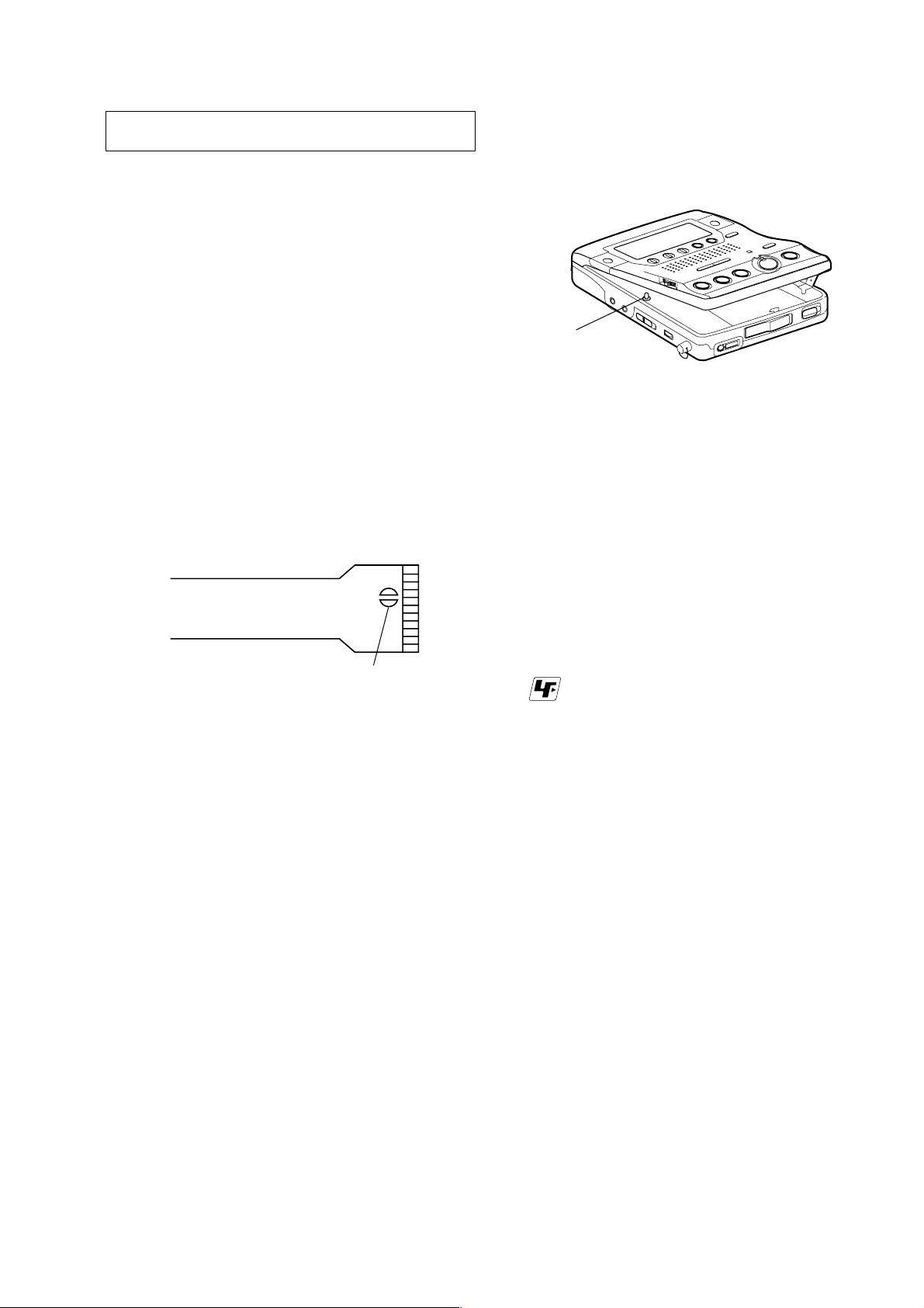
• When repairing this device with the power on, if you remove the
MAIN board or open the upper panel assy, this device stops working.
In this case, you can work without the device stopping by fastening the hook of the open/close detect switch (S804).
S804
• This set is designed to perform automatic adjustment for each
adjustment and write its value to EEPROM. Therefore, when
EEPROM (IC802) has been replaced in service, be sure to perform automatic adjustment and write resultant values to the new
EEPROM.
(Refer to Section 5 Electrical Adjustment. (page 19))
• Replacement of CXD 2671-209GA (IC801) used in this set requires a special tool.
laser-ta
OPTICAL PICK-UP FLEXIBLE BOARD
z
UNLEADED SOLDER
Boards requiring use of unleaded solder are printed with the leadfree mark (LF) indicating the solder contains no lead.
(Caution: Some printed circuit boards may not come printed with
the lead free mark due to their particular size.)
: LEAD FREE MARK
Unleaded solder has the following characteristics.
• Unleaded solder melts at a temperature about 40°C higher than
ordinary solder.
Ordinary soldering irons can be used but the iron tip has to be
applied to the solder joint for a slightly longer time.
Soldering irons using a temperature regulator should be set to
about 350°C.
Caution: The printed pattern (copper foil) may peel away if
the heated tip is applied for too long, so be careful!
• Strong viscosity
Unleaded solder is more viscous (sticky, less prone to flow)
than ordinary solder so use caution not to let solder bridges
occur such as on IC pins, etc.
• Usable with ordinary solder
It is best to use only unleaded solder but unleaded solder may
also be added to ordinary solder.
3
MZ-B100
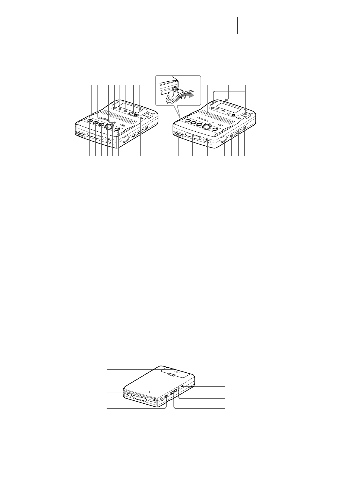
LOCATION AND FUNCTION OF CONTROLS
– Front of the recorder –
1
2
3456 78 qj qk ql
9q;qaqsqdqfqg qh w; wa ws wd wf wgwh
SECTION 2
GENERAL
How to attach the hand strap.
This section is extracted from
instruction manual.
1 SPEED CONTROL dial
2 .REVIEW/AMS/>CUE/AMS
3 VOR indicator
4 DISPLAY button
5 PLAY MODE button
6 EDIT/ENTER button
7 EASY SEARCH +/– buttons
8 Display window
9 x STOP button
0 N PLAY (play) button
qa X PAUSE button
qs z REC button
qd REC indicator
– Back of the recorder –
(search /AMS) buttons
The N PLAY button has a tactile dot.
qf TRACK MARK button
qg REC MODE switch
qh GROUP button
qj Speaker
qk DC IN 3V jack
ql Microphones
w; i (headphones) jack
wa OPEN switch
ws HOLD switch
wd VOL control
The VOL control has a tactile dot.
wf VOR button
wg SYNCHRO REC ON/OFF switch
wh ERASE button
1
2
3
1 Battery compartment
2 CLOCK SET button
3 SOUND button
4 LINE IN (OPTICAL) jack
5 MIC (PLUG IN POWER) jack
The MIC (PLUG IN POWER) jack
has a tactile dot.
6 MIC SENS (H/L) switch
4
5
6
4
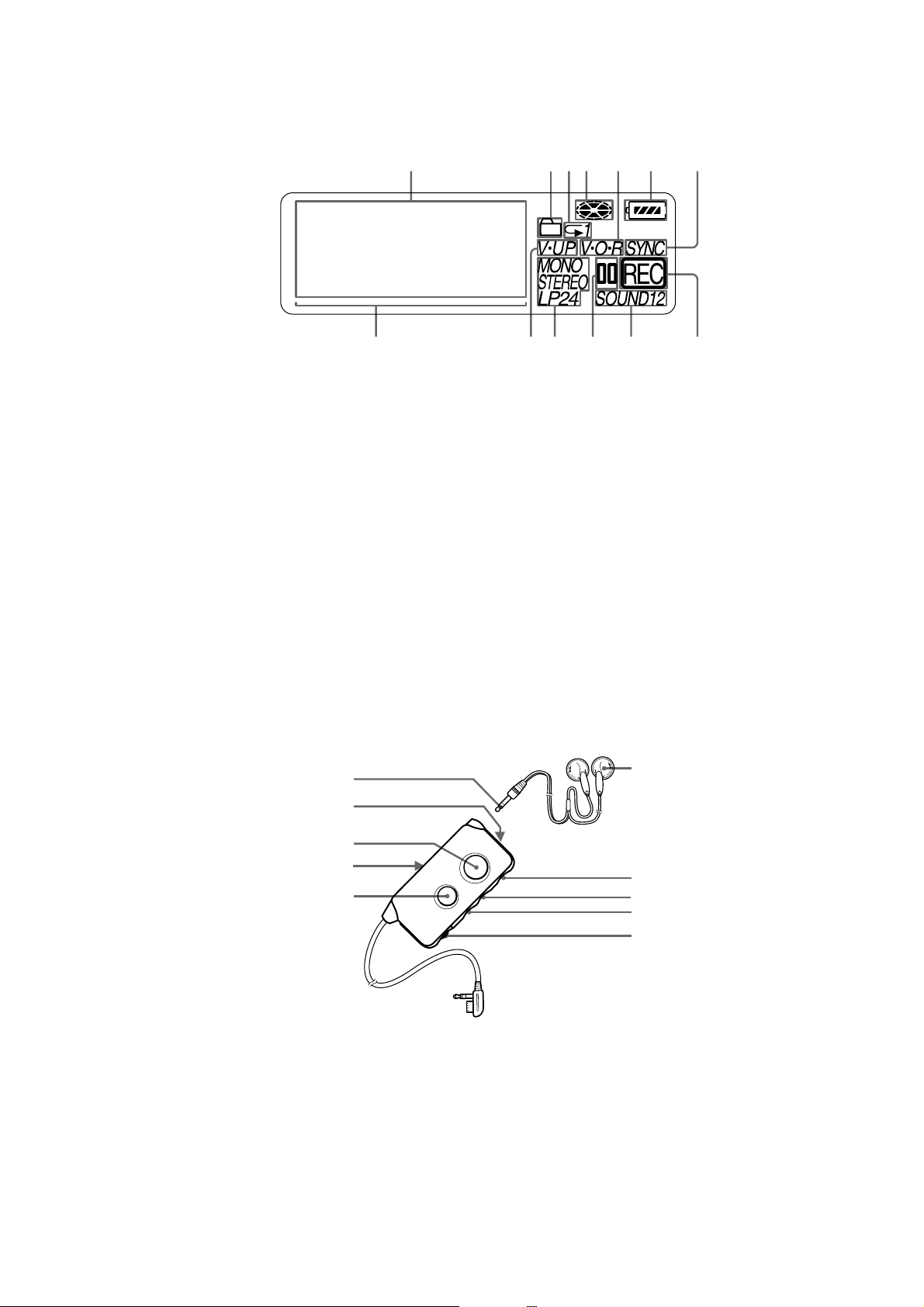
– The display window –
MZ-B100
1 2 456 7
1 Character information display
Displays the disc and track names,
date, error messages, track numbers,
recording level, etc.
2 Group indication
3 Play mode indication
4 Disc indication
Shows that the disc is rotating for
recording, playing or editing an MD.
5 VOR indication
3
qdqsqaq;98
6 Battery level indication
7 SYNC (synchro-recording) indication
8 Playback level meter
9 V-UP indication
0 STEREO (stereo), LP2 (LP2 stereo),
LP4 (LP4 stereo), MONO (monaural)
indication
qa Pause indication
qs SOUND indication
qd REC indication
– The remote control –
1 Stereo mini plug
2 SOUND button
3 TRACK MARK button
4 HOLD switch
5 X (pause) button
A
B
C
D
E
Slide to lock the controls of the remote
control.
F
G
H
I
J
6 Headphones
7 x (stop) button
8 >N buttons
The >N buttons has a tactile dot.
9 .REVIEW/AMS
0 VOL control
The VOL control has a tactile dot.
5
MZ-B100
SECTION 3
DISASSEMBLY
z
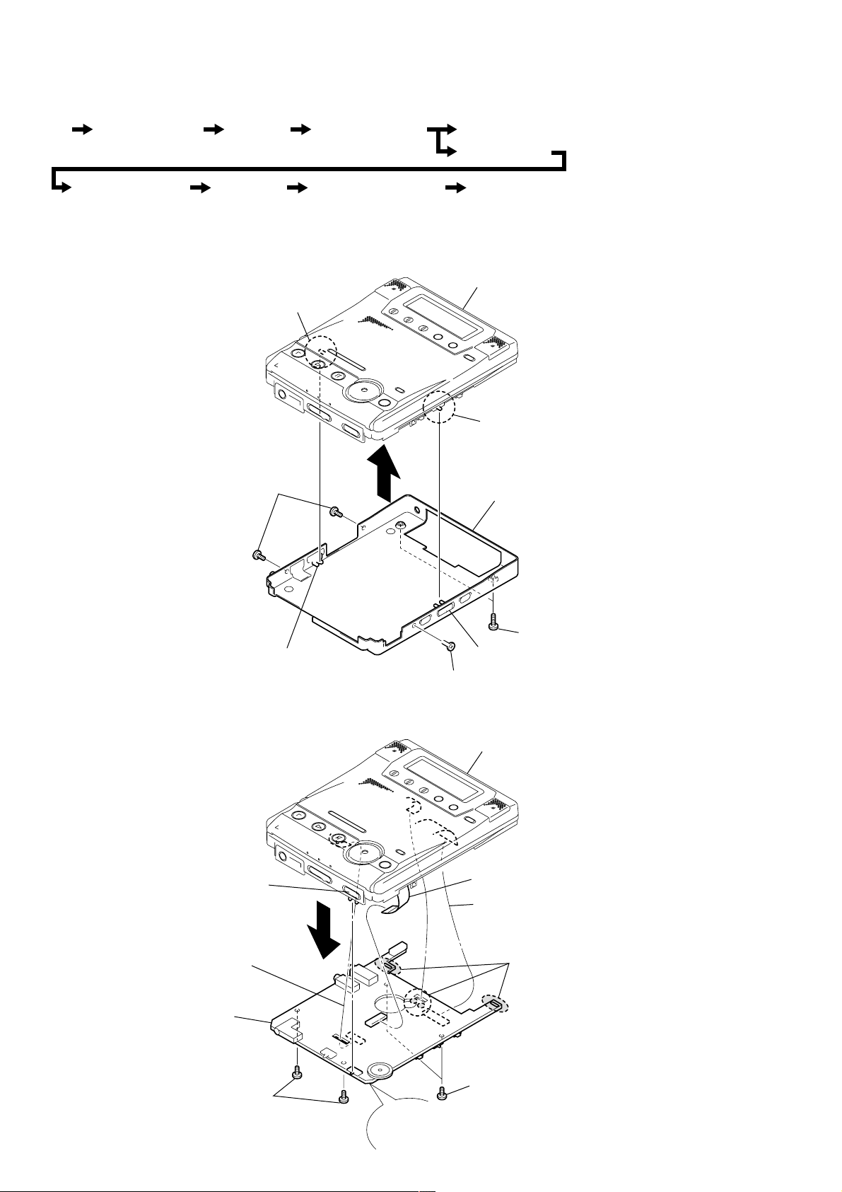
The equipment can be removed using the following procedure.
Set Main board Cabinet (belt) section Key board unit
Note : Follow the disassembly procedure in the numerical order given.
3-1. PANEL (LOWER) ASSY
Panel (lower) ASSY
Mechanism deck
Optical pick-up block Holder ASSY Motor, DC (sled) (M602) Motor, DC (spindle) (M601) ,
Motor, DC (over write head up/down) (M603)
Panel (upper lid) ASSY
S301
S809
3
2
Screws
(ES lock)
Panel (lower) ASSY
z
Caution during assembly
Position the SYNCHRO REC
knob and the S809, position the
MIC SENS knob and the S301
respectively.
3-2. MAIN BOARD
MIC SENS knob
Hold knob
4
CN701
Main board
5
1
Screws (B1.7x4)
SYNCHRO REC knob
2
Screws (ES lock)
Panel (upper lid) ASSY
6
CN501
2
CN801
3
Remove solder
(4 places)
1
1
Screws
z
Caution during assembly
Position the hold knob and
the S801 respectively
Screws
6
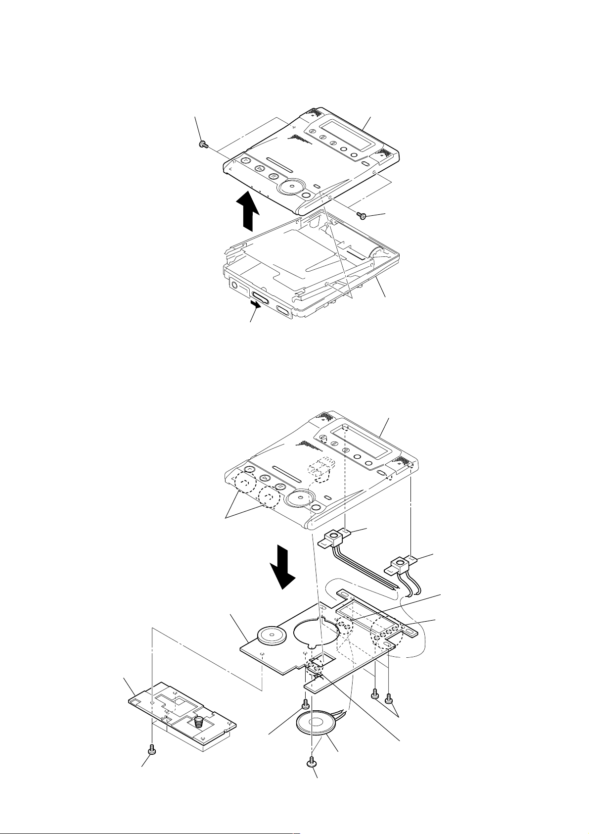
3-3. CABINET (BELT) SECTION
)
r
MZ-B100
3-4. KEY BOARD UNIT
1
Screws
(ES lock)
3
2
Open
Panel (upper lid) ASSY
1
Screws (ES lock
Cabinet (belt) section
2
Cover (REC)
9
Claws
Key board unit
0
Panel (upper lid) ASSY
MIC101
MIC201
7
Remove solde
(2 places)
6
Remove solder
(4 places)
1
Screws
5
Screw
4
Speaker
3
Screws (B2.0)
5
Screws
8
Remove solder
(2 places)
7
MZ-B100
Ver 1.2 2002.07
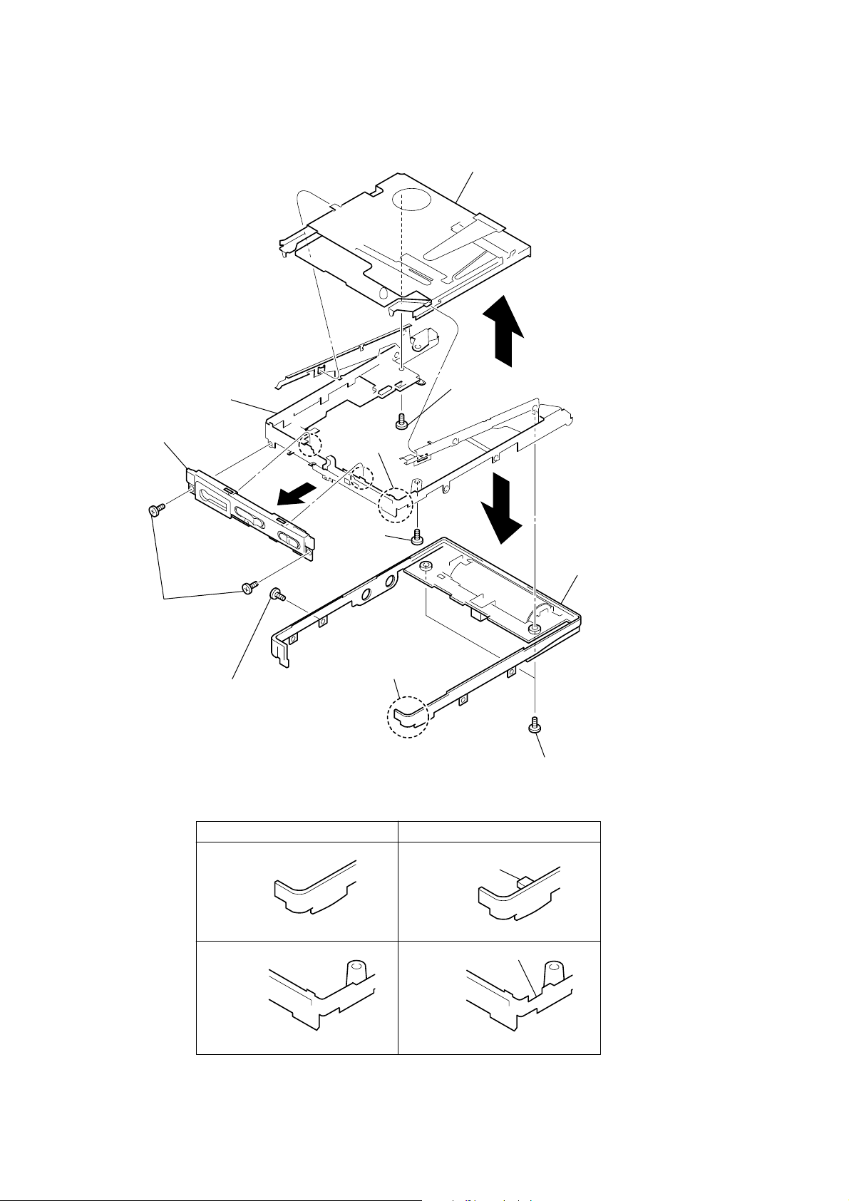
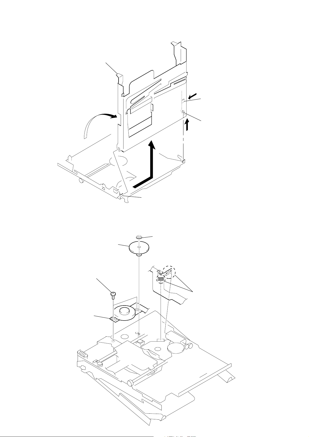
3-5. MECHANISM DECK
Set chassis ASSY
Mechanism deck
(MT-MZB100-171)
8
7
Screws
(ES lock)
Cabinet (front)
1
Screws
(ES lock)
4
Screw
(ES lock)
section A
2
6
Former Type
Section B
Screws
(ES lock)
Section A
section A
5
New Type
Projection
Cabinet (belt)
3
Screws (ES lock)
CABINET (BELT)
section B
SET CHASSIS ASSY
CABINET (BELT)
section B
Clipped portion
SET CHASSIS ASSY
NOTE: When use former type set chassis ASSY is combined with new type
cabinet (belt), scrape the projection of the cabinet (belt).
8
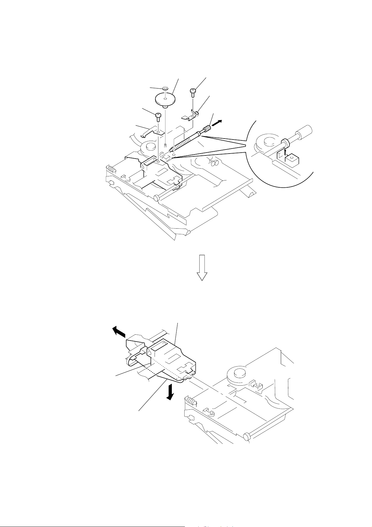
3-6. OPTICAL PICK-UP BLOCK (LCX-4R)
1
washer (0.8-2.5)
3
screw (M1.4)
4
spring, rack
2
gear (SA)
5
screw (M1.4)
6
spring, thrust detent
8
Pull off “screw, lead”
MZ-B100
7
B
Optical pick-up block (LCX-4R)
over write head section
9
Opening the over write head
toward the direction
(LCX-4R) toward the direction
Note: Do not open the entire assy forcibly,
when opening the over write head.
A
A
, remove the optical pick-up block
B
.
9
MZ-B100
3-7. HOLDER ASSY
5
Remove the holder assy in the
direction of arrow D.
1
Open the holder assy.
A
D
C
B
2
Push the convex portion
toward the direction B and
open the holder assy toward
the direction A to erect uprightly.
3
Remove the concave portion
in the direction of arrow C.
3-8. MOTOR, DC (SLED) (M602)
4
two screws (M1.4)
5
motor, DC (sled) (M602)
3
gear (SA)
4
boss
2
washer (0.8-2.5)
1
Remove six solders of
motor flexible board.
10
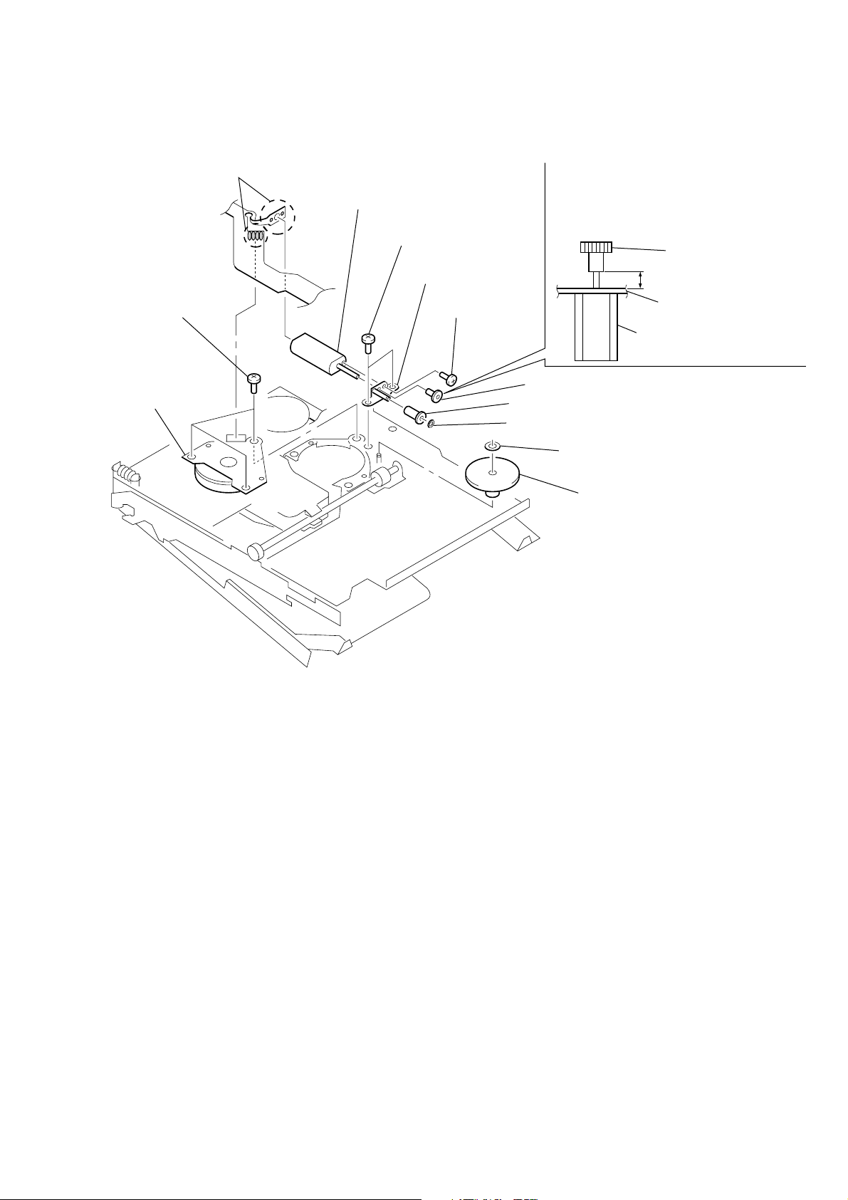
5
motor, DC
(spindle) (M601)
4
three screws
(M1.4)
1
Remove six solders of
motor flexible board.
qa
motor, DC (over write head up/down)
(M603)
6
two screws (M1.4)
qs
chassis assy, gear
9
screw (M1.2)
0
gear (HA)
gear (HA)
chassis assy, gear
2.65 mm
motor, DC (over write head
up/down) (M603)
8
gear (HB)
7
washer (0.8-2.5)
2
washer (0.8-2.5)
3
gear (HC)
Note: Press-fit the gear (HA) up to the
position of the “motor, DC (over
write head up/down) (M603) as shown
below.
3-9. “MOTOR, DC (SPINDLE) (M601)”, “MOTOR, DC (OVER WRITE HEAD UP/DOWN) (M603)”
MZ-B100
11
MZ-B100
Ver 1.3
SECTION 4
TEST MODE
[Outline]
• This set provides the Overall adjustment mode (Assy mode) that
allows CD and MO disc to be automatically adjusted when in
the test mode. In this overall adjustment mode, the protect switch
is detected to judge the disc, CD or MO, and each adjustment is
automatically executed in order. If a fault is found, the system
displays its location. Also, the manual mode allows each individual adjustment to be automatically adjusted.
• The keys in the description refer to the keys on both set and
remote commander unless otherwise specified.
[Setting Method of Test Mode]
There are two different methods to set the test mode:
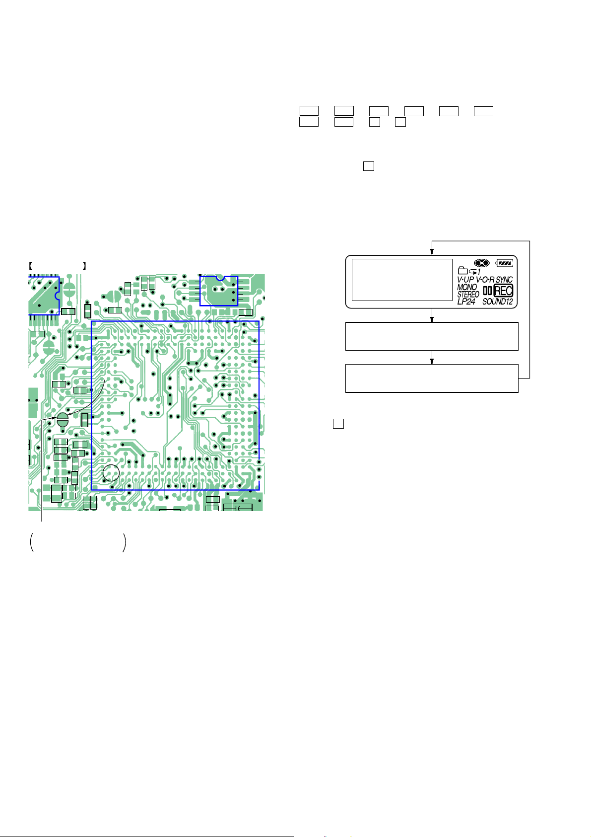
1 Short SL801 (TEST) on the MAIN board with a solder bridge
(connect pin 202 of IC801 to the ground). Then, turn on the
power.
MAIN BOARD (SIDE A)
C518
4440
R801
C517
R817
R804
SL801(TEST)
OPEN: NORMAL MODE
SHORT: TEST MODE
R803
C808
R812
C806
1
IC804
4
8
5
C805
2 In the normal mode, turn on the HOLD switch on the set. While
pressing the EASY SEARCH (-) key on the set, press the following set keys in the following order:
> t > t . t . t > t . t
> t . t X t X
[Operation in Setting the Test Mode]
• When the test mode becomes active, first the display check mode
is selected. (Press x key once, when the display check mode
is not active.)
• Other mode can be selected from the display check mode.
• When the test mode is set, the LCD repeats the following display.
LCD display
All lit
All off
Microprocessor
version
display
V0.000
R802
R819
C817
R820
R830
C816
C823
R825
R828
R827
R829
C821
R811
R810
SL801
SHORT: TEST MODE
OPEN: NORMAL MODE
*
IC801
X801
R821
• When the X key is pressed and hold down, the display at that
time is held so that display can be checked.
[Releasing the Test Mode]
For test mode set with the method 1:
Turn off the power and open the solder bridge on SL801 (TEST)
on the MAIN board.
Note: Remove the solders completely. Remaining could be shorted with
the chassis, etc.
For test mode set with the method 2:
Turn off the power.
Note: If electrical adjustment (see page 19) has not been finished com-
pletely, always start in the test mode. (The set cannot start in normal mode.)
12
MZ-B100
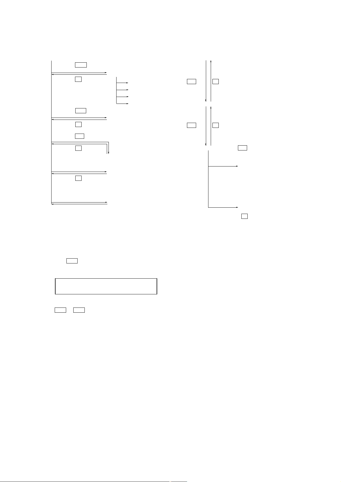
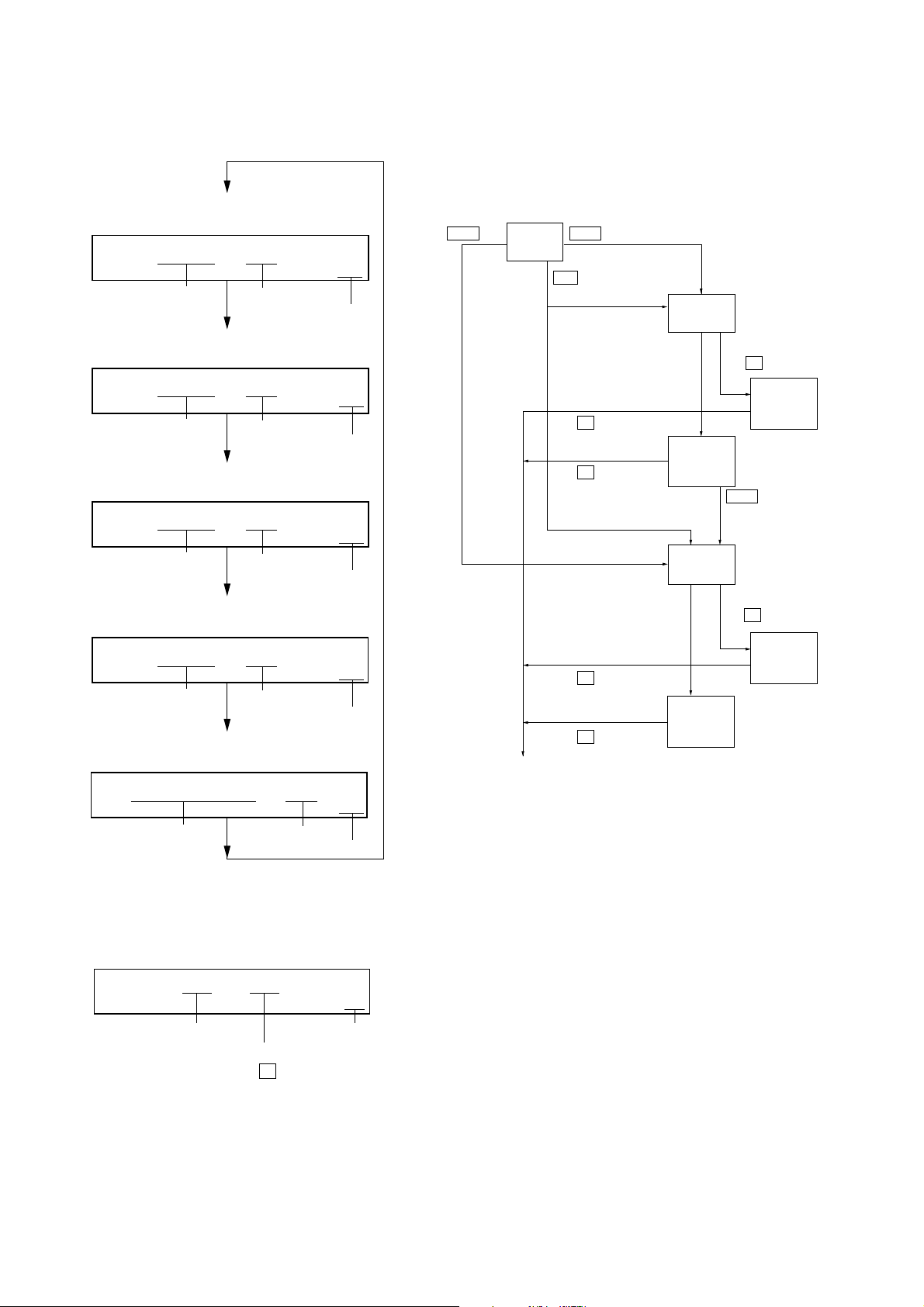
[Configuration of Test Mode]
[Test Mode $Display Check Mode%]
Press the
> or
[EASY SEARCH +]
key
[Manual Mode]
Press the
x key
[Servo Mode]
[Audio Mode]
[Power Mode]
[OP Alignment Mode]
Press the
. or
[EASY SEARCH --]
key
[Overall Adjustment Mode]
Press the
Press the N or
Press the
x key
x key
[REC]
key on the set
[Sound Skip Check Result Display Mode]
Press the
[DISPLAY]
key
[Self-Diagnosis Display Mode]
Press the
Press the
on the remote commander for several seconds.
x key
[TRACK MARK]
key
[Key Check Mode]
Quit the key check or open the upper panel
[Manual Mode]
Mode to adjust or check the operation of the set by function.
Normally, the adjustment in this mode is not executed.
• Transition method in Manual Mode
1. Setting the test mode. (See page 12)
2. Press the
mode where the LCD display as shown below.
> or [EASY SEARCH +] key activates the manual
LCD display
Manual
[Major item switching]
N
key x key
[Medium item switching]
N
key
x
key
[Minor item switching]
[EASY SEARCH +]
[EASY SEARCH --]
[EASY SEARCH +]
[EASY SEARCH --]
N
key: Unit place of mode number
increase.
key: 100th place of
mode number
increase.
key: 100th place of
mode number
decrease.
key: 10th place of
mode number
increase.
key: 10th place of
mode number
decrease.
[Adjusted value variation]
[EASY SEARCH +]
[EASY SEARCH --]
key: Increases the
key: Decreases the
[Adjusted value write]
X
key: When adjusted value is
changed:
Adjusted value is written.
When adjusted value is
not changed:
That item is adjusted
automatically.
adjusted value
adjusted value
3. The optical pick-up moves outward or inward while
the > or . key is pressed for several seconds respectively.
4. Each test item is assigned with a 3-digit mode number;
100th place is a major item, 10th place is a medium item, and
unit place is a minor item.
13
MZ-B100
r
5. Set the mode No. to 011. The display changes a shown below
each time the [DISPLAY] key is pressed.
• Address & Adjusted Value Display
LCD display
C68S01
011
address
• Jitter Value & Adjusted Value Display
LCD display
0FFJ01
jitter value
• Block Error Value & Adjusted Value Display
LCD display
adjusted value
mode number
011
adjusted value
mode number
063B01
011
block error value
• ADIP Error Value & Adjusted Value Display
LCD display
adjusted value
mode number
059A01
011
ADIP error value
• Item Title Display
LCD display
LrefPw 01
item title
adjusted value
mode number
011
adjusted value
mode number
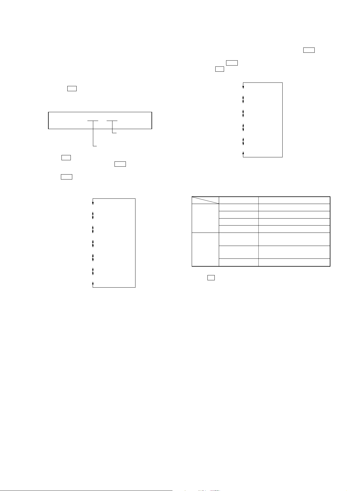
[Overall Adjustment Mode]
Mode to adjust the servo automatically in all items.
Normally, automatic adjustment is executed in this mode at the
repair.
Adjust the CD first, when performing adjustment.
• Configuration of overall adjustment
> key . key
Title
display
N key
protect switch ON
protect switch OFF
x key
x key
x key
x key
CD overall
adjusting
All item
OK
CD overall
adjustment
MO overall
adjusting
MO overall
adjustment
OK
> key
NG item exists
or
OK
NG item exists
x key
or
CD overall
adjustment
NG
x key
MO overall
adjustment
NG
[Test mode $display check mode%]
For further information, refer to the Section 5 Electrical Adjustment. (See page 19)
However in the power mode (mode number 700’s), only the
power adjustment value is displayed.
• Power Supply Adjusted Value
LCD display
AD 85
731
fixed display mode numbe
adjusted value
6. Quit the manual mode, and press
mode (display check mode).
14
x key to return to the test
MZ-B100
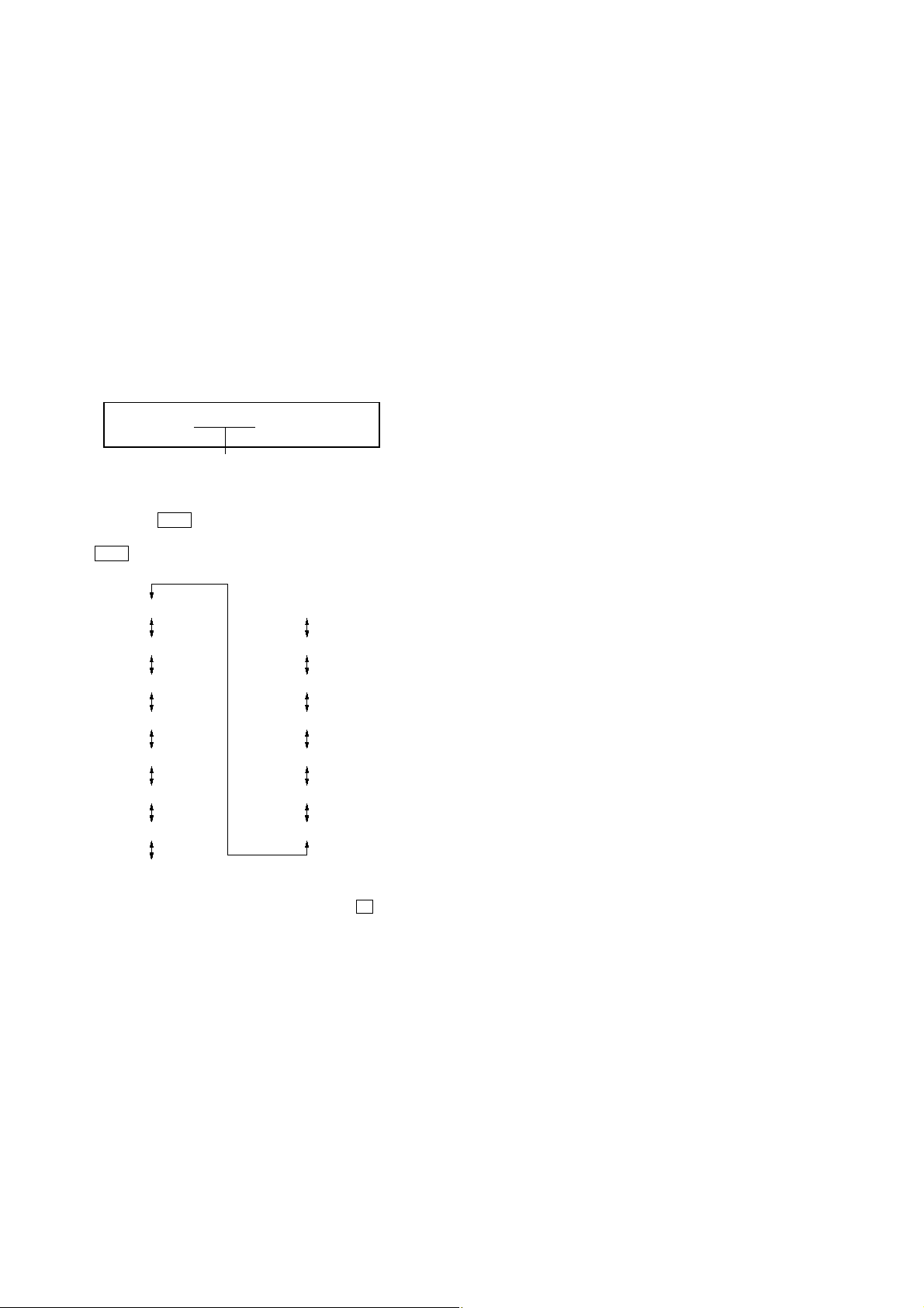
[Sound Skip Check Result Display Mode]
This set can display and check the error count occurring during
record and play.
• Setting method of Sound Skip Check Result Display
Mode
1. Setting the test mode. (See page 12)
2. Press the N or [REC] key on the set activates the sound skip
check result display mode where the LCD displays as shown
below.
LCD dispaly
P**R**
000
Total of record system
error count
Total of play system error count
3. When N key is pressed, the total of error count is displayed
on the LCD, and each time the > key is pressed, the error
count descents one by one as shown below. Also,
when . key is pressed, the error count ascends by one. If
[REC] key on the set is pressed, the error count during record
is displayed.
P**R**
EIB **
Stat**
Adrs**
BEmp**
######
000
000
000
000
000
000
4. When [REC] key on the set is pressed, the total of error count
is displayed on the LCD, and each time the > key is
pressed, the error count descents one by one as shown below.
Also, when . key is pressed, the error count ascends by
one. If N key is pressed, the error count during play is displayed.
P**R**
Bovr**
BFul**
Rtry**
######
**
: Sound skip check items counter (hexadecimal)
######
: 6-digit address (hexadecimal) where a sound skipped
last
000
000
000
000
000
Error code
Cause of error Description of error
EIB Sound error correction error
Playback
Recording BFul Buffer capacity lowers and data are
Stat Decorder status error
Adrs Cannot access the address
BEmp Buffer becomes empty
BOvr Buffer becomes full and sounds are
dumped
forcibly written
Rtry Retry count over
5. Quit the sound skip check result display mode, and press
the x key to return to the test mode (display check mode).
**
: Sound skip check items counter (hexadecimal)
######
: 6-digit address (hexadecimal) where a sound skipped
last
15
MZ-B100
[Self-Diagnosis Display Mode]
• This set uses the self-diagnosis system in which if an error oc-
curs in recording/playback mode, the error is detected by the
model control and power control blocks of the microprocessor
and information on the cause is stored as history in EEPROM.
By viewing this history in test mode, it helps you to analyze a
fault and determine its location.
Total recording time has been recorded as optical pick-up using
time, and it is compared with the total recording time in the
self-diagnosis display mode to find when an error occurred.
Clear both total recording time and the time in self-diagnosis
display mode, when the optical pick-up was replaced.
1. Setting the test mode. (See page 12)
2. Press the [DISPLAY] key activates the self-diagnosis display
mode where the LCD display as shown below.
LCD dispaly
1st0**
000
history code
** : Self-Diagnosis Data
3. Then, each time > key is pressed, LCD display descends
by one as shown below. Also, the LCD display ascends by one
when . key is pressed.
000
1st0**
000
1st1**
000
1st2**
000
N 0**
000
N 1**
000
N 2**
000
N-10**
1
4. Quit the self-diagnosis display mode, and press the
return to the test mode (display check mode).
1
000
N-11**
000
N-12**
000
N-20**
000
N-21**
000
N-22**
000
R ####
x key to
16
• Description of Indication History
History code number Description
1st0 The first error
1st1 Total recording time when 1st0 was generated (Higher rank byte)
1st2 Total recording time when 1st0 was generated (Lower rank byte)
N 0 The last error
N 1 Total recording time when N 0 was generated (Higher rank byte)
N 2 Total recording time when N 0 was generated (Lower rank byte)
N-10 One error before the last.
N-11 Total recording time when N-10 was generated (Higher rank byte)
N-12 Total recording time when N-10 was generated (Lower rank byte)
N-20 Two errors before the last.
N-21 Total recording time when N-20 was generated (Higher rank byte)
N-22 Total recording time when N-20 was generated (Lower rank byte)
REC Total recording time *
MZ-B100
* Total recording time
Total recording time is recorded in
minutes. It is recorded in hexadecimal
format and up to 65,535 min. can be
counted. It returns to “0000min” when
recorder goes beyond this limit.
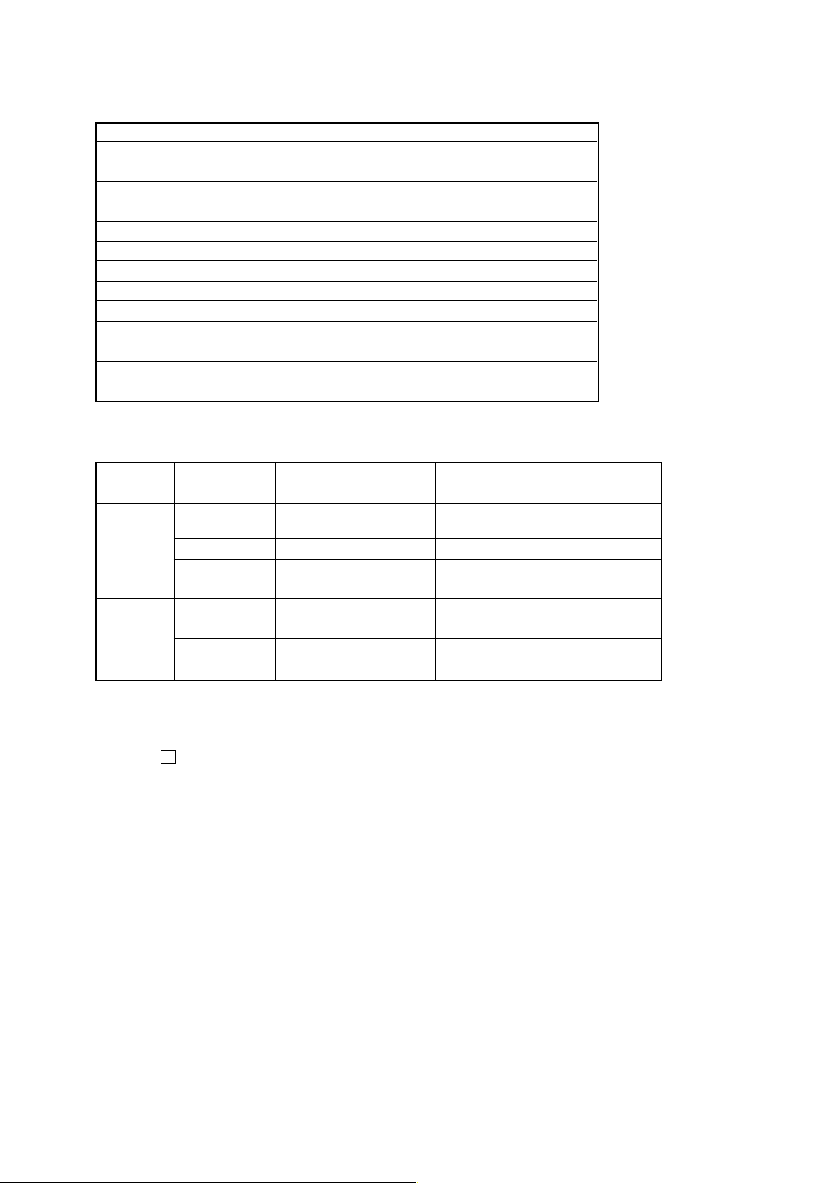
• Description of Error Indication Codes
Problem Indication code Meaning of code Description
No error 00 No error
01
Servo error 02 High temperture High temperture
03 Focus error Forcus could not be applied
04 Spindle error Abnormal lotation of disc
21 Initial low battery Abnormal voltage at initialization
Power error
22 Low battery Momentary interruption detected
23 Low battery NI Momentary interruption detected (NiMH)
24 Low battery AM Momentary interruption detected (AM)
Illegal access target address Attempt to access an abnormal address
was specified
[Clearing Self-Diagnosis Data and Total Recording Time]
1. Setting the test mode. (See page 12.)
2. Move up the jog key on the set or press the [DISPLAY] key on the remote commander activates the self-diagnosis display mode.
3. Press the X key or [REC] key on the set during display of self-diagnosis data when clearing the self-diagnosis data, or during display of
total recording time when clearing the total recording time. Thus, “ClrOK?” will be displayed on the LCD, and press the same key again,
and when self-diagnosis data is cleared “ErrCLR” is displayed and the data is cleared. Also when total recording time is cleared, “ ReeT
O” is displayed and it is cleared.
17
MZ-B100
[Key Check Mode]
This set can check if the set and remote commander function normally.
• Setting Method of Key Check Mode
1. Setting the test mode. (See page 12)
2. Press the [T MARK] activates the key check mode where all
segments of LCD turn OFF. (At the last two digits of DOT
section, AD value of remote commander key line is displayed
in hexadecimal)
3. When each key is pressed, it is displayed on the LCD, imply-
ing that it was successfully checked as shown below. However, for the slide switch on the set, it is not checked unless it
is reciprocated.
* The key pressed to enter the key check mode was already
checked at that time.
Set key
Key Indication
N PLAY
> FF
. FR
X PAUSE
EASY SEARCH + EASY +
EASY SEARCH – EASY –
x STOP
REC REC
TRACK MARK T MARK
HOLD (hold) HLDon
HOLD (off) HLDoff
SYNCHRO REC (on) SYCon
SYNCHRO REC (off) SYCoff
PLAY MODE P MODE
DISPLAY DISP
EDIT/ENTER MENU
VOR VOR
ERASE ERASE
REC MODE R-MODE
GROUP GROUP
Remote commander key
Key Indication
N/> rPLAY
. rFR
X rPAUSE
x rSTOP
TRACK MARK rREP
V-UP rSOUND
4. The test mode (display check mode) is automatically activated
when all keys on the set and remote commander were checked
(see above). Also, the test mode (display check mode) gets
back if opening the upper panel during a key check.
18

SECTION 5
ELECTRICAL ADJUSTMENTS
MZ-B100
[Outline]
• In this set, automatic adjustment of CD and MO can be performed by entering the test mode. (See page 12)
However, before starting automatic adjustment, the memory
clear, power adjustment and temperature adjustment must be
performed in the manual mode.
• The keys in the description refer to the keys on both set and
remote commander unless otherwise specified.
Though LCD display shows the LCD of the remote commander,
same contents are also displayed on the LCD of the set.
[Precautions for Adjustment]
1. Adjustment must be done in the test mode only.
After adjusting, release the test mode.
2. Use the following tools and measuring instruments.
• Test CD disc TDYS-1
(Part No. : 4-963-646-01)
Available SONY CD disc
• Recorded MO disc PTDM-1
(Part No. : J-2501-054-A)
Available SONY MO disc (recorded)
• Laser power meter LPM-8001
(Part No. : J-2501-046-A)
• Digital voltmeter
3. Unless specified otherwise, supply DC 3V from the DC IN 3V
jack.
4. Switch position
HOLD switch ................OFF
[Adjustment Sequence]
Adjustment must be done with the following steps.
1. NV Reset (Memory clear)
r
2. Power Supply Manual Adjustment Manual Mode
r
3. Temperature correction
r
4. CD Overall Adjustment
r Overall Mode
5. MO Overall Adjustment
[NV Reset]
• Setting method of NV reset
1. Select the manual mode of test mode, and set mode number 021NV Reset.
LCD display
ResNV
021
2. Press the X key.
LCD display
ResOK?
021
3. Press the X key once more.
LCD display
Res***
021
r NV reset (after several seconds)
Reset!
021
4. Quit the manual mode, and activate the test mode.
[Power Supply Manual Adjustment]
• Adjustment sequence
Adjustment must be done with the following steps.
1. VC PWM Duty (L) adjustment (mode number: 762)
r
2. VREM PWM Duty (H) adjustment (mode number: 763)
r
3. VREM PWM Duty (L) adjsutment (mode number: 764)
r
4. VC PWM Duty (H) adjustment (mode number: 765)
r
5. VREM PWM Duty (H) adjustment (mode number: 766)
r
6. VREM PWM Duty (L) adjustment (mode number: 767)
19
MZ-B100
C9
9
C922
2
C9
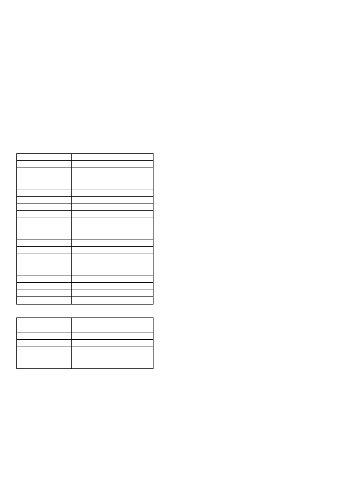
• Adjustment method of VC PWM Duty (L)
(mode number: 762)
1. Select the manual mode of the test mode, and set the mode
number 762. (See page 13)
LCD display
VclPWM
762
2. Connect a digital voltmeter to the AP913 (VC) on the MAIN
board, and adjust
[EASY SEARCH +] key (voltage up) or
[EASY SEARCH --] key (voltage down) so that the voltage
becomes 2.5 ± 0.02 V.
Proceed to the next step without pressing X key if voltage is
already adjusted.
digital
voltmeter
AP913 (VC)
AP909
(GND)
MAIN BOARD
(SIDE A)
AP912
C926
C925
C924
15
3. Press the X key to write the adjusted value.
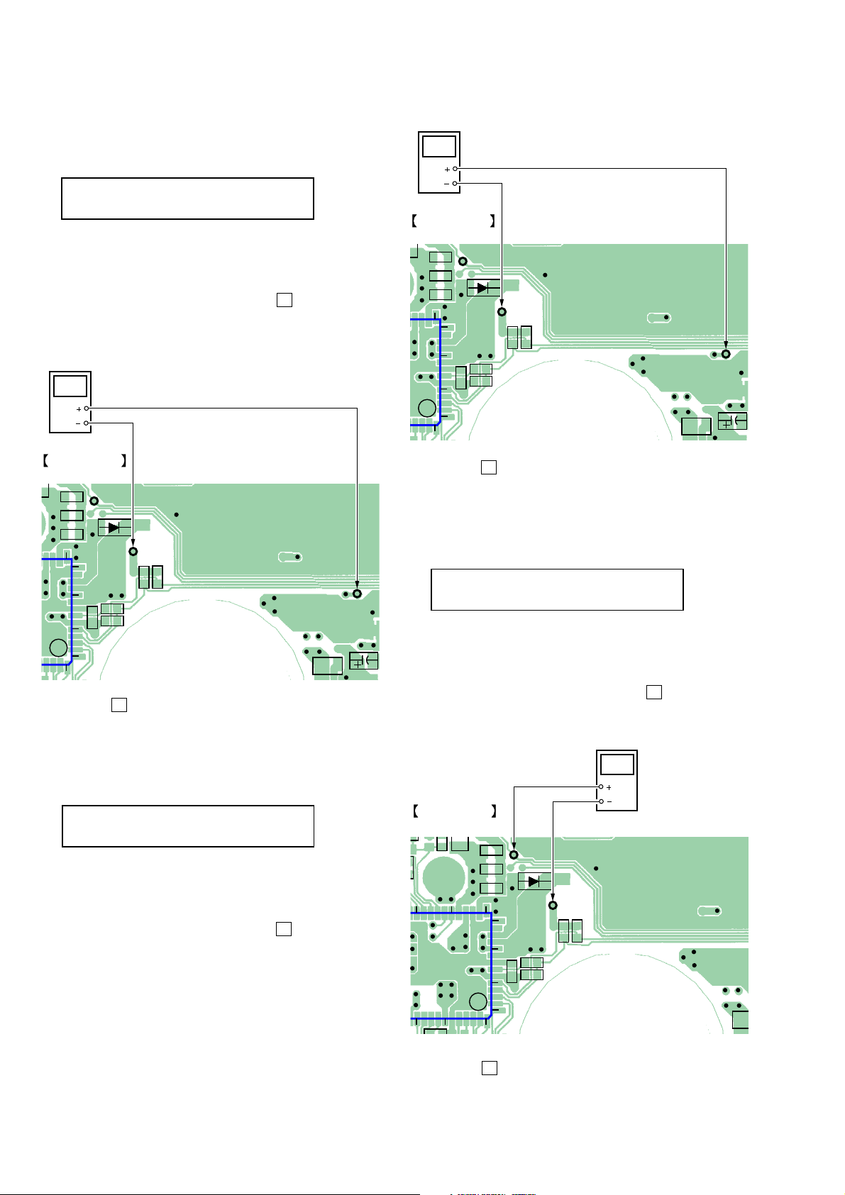
• Adjustment method of VREM PWM Duty (H)
(mode number: 763)
1. Select the manual mode of the test mode, and set the mode
number 763. (See page 13)
LCD display
(VL)
D903
AP909
14
(GND)
10
R920
R919
C913
5
1
56
C915
C912
VrhVcl
763
2. Connect a digital voltmeter to the AP913 (VC) on the MAIN
board, and adjust
[EASY SEARCH --] key (voltage down) so that the voltage
becomes 2.75 ± 0.02 V.
Proceed to the next step without pressing X key if voltage is
already adjusted.
[EASY SEARCH +] key (voltage up) or
R501
AP913
(VC)
C502
digital
voltmeter
AP913 (VC)
AP909
(GND)
MAIN BOARD
(SIDE A)
AP912
C926
C925
C924
15
(VL)
D903
AP909
14
(GND)
10
R920
R919
C913
5
1
56
C915
C912
R501
AP913
(VC)
C502
3. Press the X key to write the adjusted value.
• Adjustment method of VREM PWM Duty (L)
(mode number: 764)
1. Select the manual mode of the test mode, and set the mode
number 764. (See page 13)
LCD display
VrlVcl
764
2. Connect a digital voltmeter to the AP912 (VL) on the MAIN
board, and adjust
[EASY SEARCH --] key (voltage down) so that the voltage
becomes 2.5 ± 0.02 V.
Proceed to the next step without pressing X key if voltage is
already adjusted.
MAIN BOARD
(SIDE A)
C
R9
C926
C925
C924
15
20
25
IC901
50
45
[EASY SEARCH +] key (voltage up) or
digital
voltmeter
AP912 (VL)
AP909
(GND)
AP912
(VL)
D903
AP909
14
(GND)
10
R920
R919
C913
5
1
56
C915
C912
R5
20
3. Press the X key to write the adjusted value.
MZ-B100
C9
9
C922
2
9
C922
2
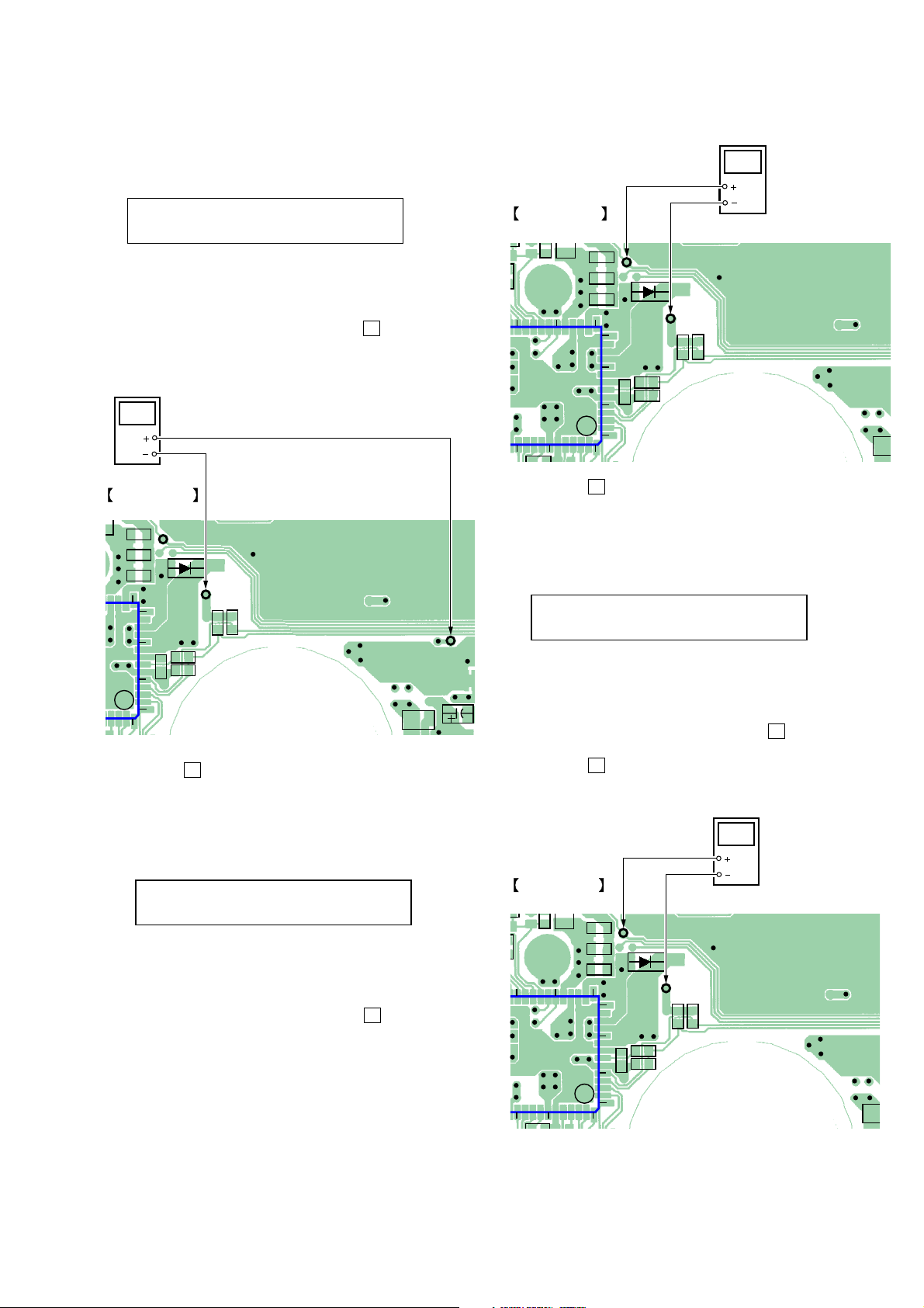
• Adjustment method of VC PWM Duty (H)
(mode number: 765)
digital
voltmeter
1. Select the manual mode of the test mode, and set the mode
number 765. (See page 13)
LCD display
VchPWM
765
2. Connect a digital voltmeter to the AP913 (VC) on the MAIN
board, and adjust
[EASY SEARCH --] key (voltage down) so that the voltage
becomes 2.75 ± 0.02 V.
Proceed to the next step without pressing X key if voltage is
already adjusted.
digital
voltmeter
AP913 (VC)
MAIN BOARD
(SIDE A)
AP912
C926
C925
C924
15
(VL)
D903
AP909
14
(GND)
10
R920
R919
C913
5
1
56
[EASY SEARCH +] key (voltage up) or
AP909
(GND)
C912
C915
R501
AP913
(VC)
C502
MAIN BOARD
(SIDE A)
C
R9
C926
C925
C924
15
20
25
IC901
50
45
56
3. Press the X key to write the adjusted value.
• Adjustment method of VREM PWM Duty (L)
(mode number: 767)
1. Select the manual mode of the test mode, and set the mode
number 767. (See page 13)
LCD display
2. Connect a digital voltmeter to the AP912 (VL) on the MAIN
board, and adjust [EASY SEARCH +] key (voltage up) or
[EASY SEARCH --] key (voltage down) so that the voltage
becomes 2.5 ± 0.02 V.
Proceed to the next step without pressing X key if voltage is
AP912 (VL)
AP909
(GND)
AP912
(VL)
D903
AP909
14
(GND)
10
R920
R919
C913
5
1
C915
VrlVch
C912
R5
767
already adjusted.
3. Press the X key to write the adjusted value.
• Adjustment method of VREM PWM Duty (H)
3. Press the X key to write the adjusted value.
digital
voltmeter
(mode number: 766)
1. Select the manual mode of the test mode, and set the mode
number 766. (See page 13)
LCD display
VrhVch
766
2. Connect a digital voltmeter to the AP912 (VL) on the MAIN
board, and adjust [EASY SEARCH +] key (voltage up) or
[EASY SEARCH --] key (voltage down) so that the voltage
becomes 2.75 ± 0.02 V.
Proceed to the next step without pressing X key if voltage is
MAIN BOARD
(SIDE A)
C
R9
20
25
C926
C925
C924
15
already adjusted.
IC901
50
45
56
14
10
5
1
AP912 (VL)
AP912
(VL)
D903
AP909
(GND)
R920
R919
C913
AP909
(GND)
C912
C915
R5
21
 Loading...