

Page 1

Table of Contents
Chapter 1 Overview
1-1 Overview ......................................................... 1-1
Chapter 2 Locations and Functions of
Parts and Controls
2-1 Construction of Control Panel and Connector
Panel ................................................................ 2-2
2-2 Input Section ................................................... 2-4
2-2-1 Mono Input Module............................... 2-4
2-2-2 Stereo Input Module .............................. 2-8
2-3 Output and Monitor Signal Section............ 2-12
2-3-1 Meter Section....................................... 2-13
2-3-2 RETURNS Section .............................. 2-14
2-3-3 SEND MASTERS Section .................. 2-15
2-3-4 MONITOR Section.............................. 2-16
2-3-5 OSCILLATOR Section........................ 2-17
2-3-6 TALKBACK Section .......................... 2-18
2-3-7 MASTER Faders ................................. 2-19
2-3-8 PHONES Section................................. 2-20
2-4 Connector Panel ........................................... 2-21
2-4-1 Mono Input Connectors ....................... 2-21
2-4-2 Stereo Input Connectors ...................... 2-22
2-4-3 Output and Monitor Signal
Connectors ........................................... 2-23
2-4-4 Control Signal Connectors................... 2-25
Chapter 3 Connection and Operation
3-1 Mixer Connection ........................................... 3-1
3-1-1 Connecting Microphones ....................... 3-1
3-1-2 Connecting Stereo Effect Units.............. 3-1
3-1-3 Connecting Audio Monitor Systems...... 3-2
3-1-4 Connecting a Power Source ................... 3-2
3-2 Mixer Operation ............................................. 3-3
3-2-1 Monitor Source Selection....................... 3-3
Appendix
Specifications......................................................... A-1
Table of contens 1
Page 2

Table of contens
2 Table of contens
Page 3

1-1 Overview
Chapter 1
Overview
The Sony MXP-310 is a multipurpose audio mixer that features all the
essential functions demanded by professional audio processing.
12 channel inputs: six mono (MIC/LINE selectable) and six stereo
(line) with many adjustment possibilities
You can adjust each input signal level independently to suit the output
signal from connected equipment and provide high-quality mixing through
the MXP-310’s low-cut filter and four-band equalizers (three of the band
equalizers are equipped with stereo inputs).
You can place each input sound image at any desired spot between the left
and right channels with the PAN POT function.
+48 V DC selectable microphone powering
On the mono input modules, the built-in power supply circuits supply 48 V
DC to the connected phantom-powered microphones (those designed for
use with an external power supply.)
Two stereo effect returns
Assignable to each master output
Console table mount
The MXP-310 can easily be placed on a control console table with the
MXBK-TK390 table kit (not supplied).
Chapter 1 Overview 1-1
Page 4

AAAAyA<H.L0.idx>
1-2 Chapter 5 Function of parts and Controls<H.L0.footer>
Page 5

Chapter 2
Locations and Functions
of Parts and Controls
This chapter gives the names and functions of the controls and other parts.
Experienced users should be able to start using the MXP-310 audio mixer
after reading this chapter.
Chapter 2
Chapter 2 Locations and Functions of Parts and Controls 2-1
Page 6
Chaper 2
2-1 Construction of Control Panel and Connector
2-2 Input Section
Panel
This section shows the construction of the control panel and connector
panel of the MXP-310.
Control Panel
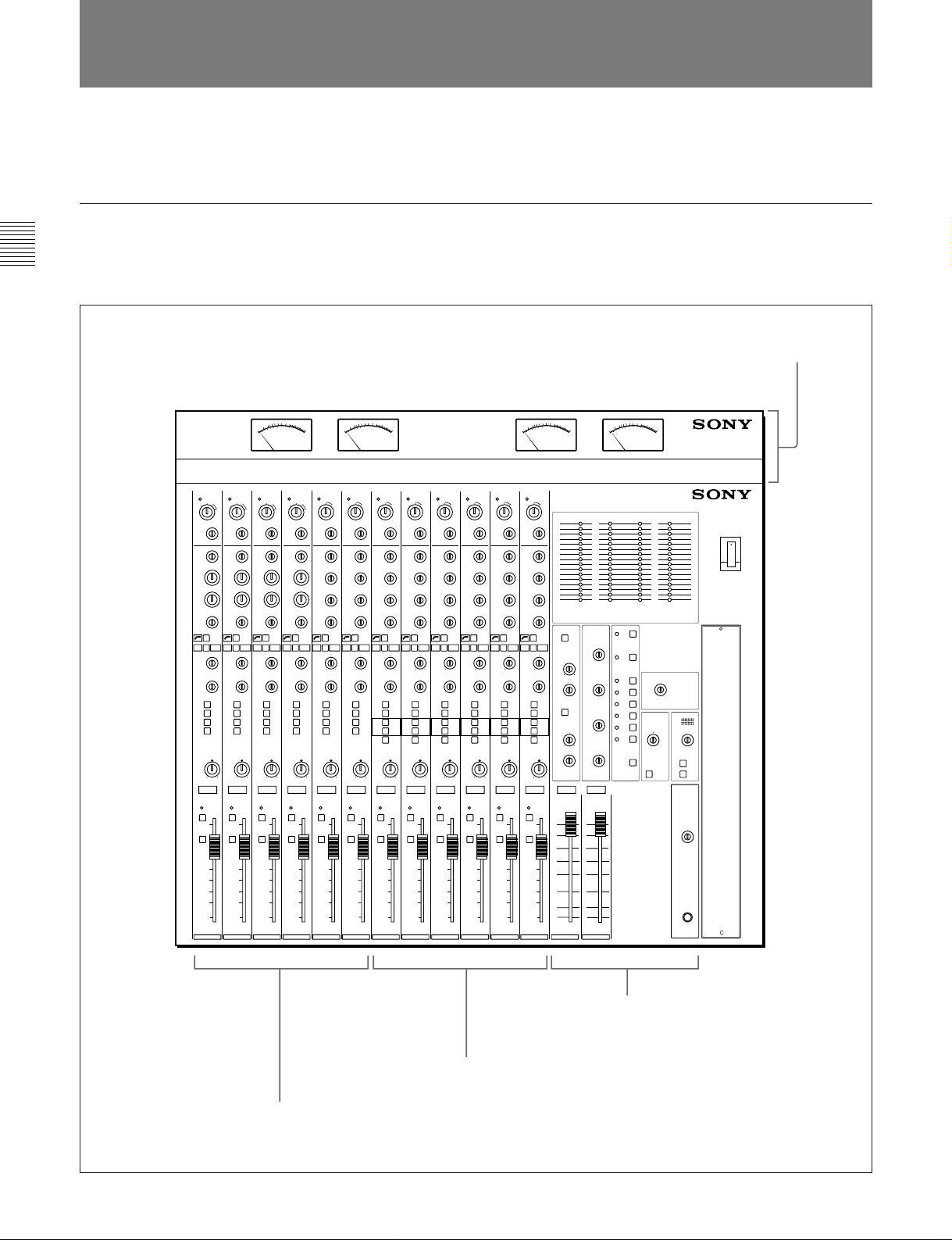
The MXP-310’s control panel consists of three sectons as shows below.
For the details of each section, see the section in the parenthesis.
MXBK-M301 VU Meter Unit
(not supplied)
12 CHANNEL AUDIO MIXER MXP-310
Stereo Input Module
(Section 2-2-2 “Stereo Input Module”on page 2-8)
Mono Input Module
(Section 2-2-1 “Mono Input Module” on page 2-4)
2-2 Chapter 2 Locations and Functions of Parts and Controls
Output and Monitor Signal Section
(Section 2-3 “Output and Monitor Signal
Section” on page 2-12)
Page 7
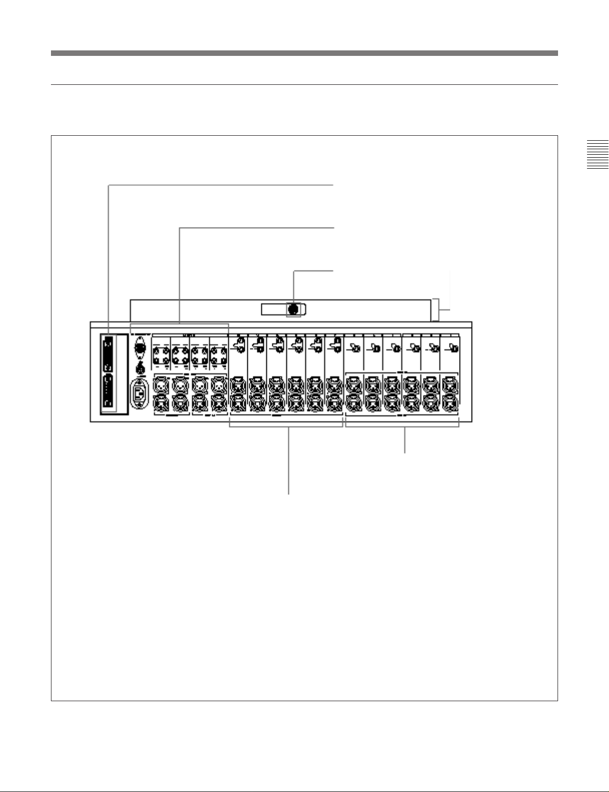
Connector panel
The MXP-310’s connector panel consists of four sections as shown below.
Control signal connector section
(Section 2-4-4 “Control Signal Connectors
Section” on page 2-25)
Output and monitor signal connector section
(Section 2-4-3 “Output and Monitor Signal
connectors” on page 2-23)
VU meter unit connector
MXBK-M301 VU meter
unit (not supplied).
Mono input connector section
(Section 2-4-1 “Mono Input
Connectors” on page 2-21)
Chapter 2
Stereo input connector section
(Section 2-4-2 “Stereo Input
Connectors” on page 2-22)
Chapter 2 Locations and Functions of Parts and Controls 2-3
Page 8
Chaper 2
2-2 Input Section
2-2 Input Section
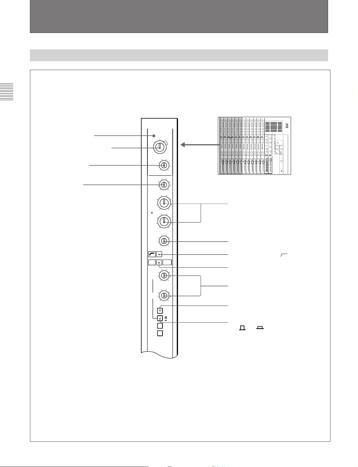
2-2-1 Mono Input Module
1 PEAK indicator
2 INPUT SELECT switch
3 TRIM control
4 HI control
PEAK
UNBAL
LINE
INPUT
SELECT
TRIM
HI
MID1
PREQ
LVL
MID2
LO
EQ
SENDS
1/3
SENDS
2/4
1
2
BAL
LINE
-60 0
-15
-12
-12
-15
0
0
MIC
PRE
MIC
+48V
+15
5 MID 1 and MID 2 controls
+12
+12
+15
6 LO control
7 Low cut filter switch [ ]
8 EQ switch
10
9 SENDS 1/3 and SEND 2/4 controls
10
1-2
3-4
0 PRE (pre-fader) switch
!¡ Auxiliary send select switch
[ 1-2/ 3-4]
(Continued on page 2-6)
2-4 Chapter 2 Locations and Functions of Parts and Controls
Page 9
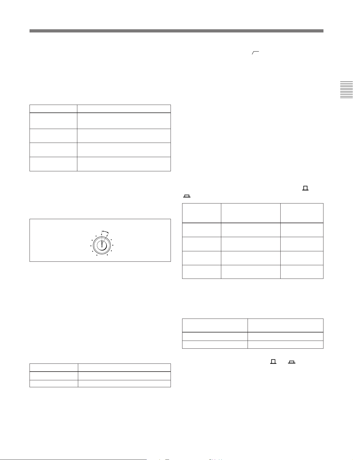
1 PEAK indicator
Lights to indicate a peak signal level of about 6 dB
below clipping level.
2 INPUT SELECT switch
Set to select the input source connected to the module
as shown below.
Switch setting Source selected
UNBAL LINE Line input connected to the UBL IN
connector
BAL LINE Line input connected to the LINE IN
MIC Microphone connected to the MIC IN
MIC +48V
a)
This setting supplies +48V DC, for condenser-type
microphones through the MIC IN connector.
a)
connector
connector
Phatom-powered condenser microphone
connected to the MIC IN connector
3 TRIM (input gain) control
Turn to adjust the level of the signal selected with the
INPUT SELECT switch.
Setting range for unity gain
TRIM
-30 0
4 HI (high frequency boost and cut) control
When the EQ switch 8 is pressed, a 10 kHz shelvingtype equalizer is engaged. Turn this knob to boost or
cut by ±15 dB (max.).
5 MID 1 (midrange frequency 1) and MID 2
(midrange frequency 2) controls
When the EQ switch 8 is pressed, the midrange
frequency peaking-type equalizers are engaged. Turn
the inner knobs to boost or cut the mid range by ±12
dB (max.). Turn the outer knobs to control the center
frequencies.
Outer knob Center frequencies selected
MID 1 outer knob 800 Hz to 8 kHz
MID 2 outer knob 150 Hz to 2.5 kHz
6 LO (low frequency boost and cut) control
When the EQ switch 8 is pressed, the 100 Hz
shelving-type equalizer is engaged. Turn this knob to
boost or cut by ±15 dB (max.).
7 Low cut filter switch [ ]
Press to engage a 12 dB/octave filter below
100 Hz. This switch operates independently of the EQ
switch 8.
8 EQ (equalizer) switch
Press to engage the equalizer. When the switch is
released, the HI, MID1, MID2 and LO equalizer
controls are removed from the signal path.
9 SENDS 1/3 (auxiliary send bus 1 and 3 level)
and SENDS 2/4 (auxiliary send bus 2 and 4 level)
controls
Turn to control the level of the channel signal sent to
the corresponding auxiliary send buses: 1 and 3, or 2
and 4. Turn the control fully clockwise for the unity
gain.
Use either knob after selecting the desired auxiliary
send bus with the auxiliary send select switch [ 1-2/
3-4]!¡, as shown below.
To control Set the auxiliary send Then, adjust:
the auxiliary select switch to:
send bus of
SEND 1 Released position SENDS 1/3
control
SEND 2 Released position SENDS 2/4
control
SEND 3 Depressed position SENDS 1/3
control
SEND 4 Depressed position SENDS 2/4
control
0 PRE (pre-fader) switch
Press to determine the point where the channel signal
is fed to the auxiliary send buses, as shown below.
Set the switch to: Then, the auxiliary send
signal will be output from:
Released position Post fader point
Depressed position Pre-fader point
!¡ Auxiliary send select switch [ 1-2/ 3-4]
Press to select the auxiliary send buses to which the
channel signal is sent. You can control the level of
each auxiliary send bus by using this switch and either
the SENDS 1/3 control or SENDS 2/4 control, as
shown in the table in the SENDS 1/3 and 2/4 controls
9.
You can route the channel signal to two send buses
SEND 1 and 2 (or SEND 3 and 4) at a time.
Chapter 2
Chapter 2 Locations and Functions of Parts and Controls 2-5
Page 10
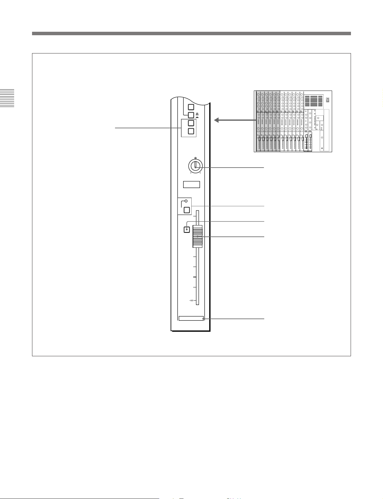
2-2 Input Section
(Continued from page 2-4)
Chaper 2
!™ Line output switches [1, 2]
1
2
MUTE
PFL
PRE
1-2
3-4
LR
PAN
12
6
0
-6
-12
-24
-36
-60
!£ PAN control
!¢ MUTE switch and indicator
!∞ PFL switch
!§ Channel fader
2-6 Chapter 2 Locations and Functions of Parts and Controls
1
Channel number
Page 11
!™ Line output switches [1, 2]
Press to assign the post fader signal to the selected line
output buses. One channel can be assigned to two
output buses simultaneously.
!£ PAN (pan pot) control
Turn to adjust the relative level of the post fader signal
sent to the line output buses selected by the line output
select switches !™, as shown below.
If you adjust the Then, the post fader signal is
PAN control to: sent to:
Fully towards “L” Output bus 1 only
Fully towards “R” Output bus 2 only
“C” position Equally to the 1 and 2 busses
!¢ MUTE (channel mute) switch and indicator
Press to mute the post fader signal. The MUTE
indicator lights when the MUTE switch is engaged.
This switch has no effect on the auxiliary send buses
when the PRE switch 0 is depressed.
!∞ PFL (pre-fader listening) switch
Press to send the pre-fader signal to the PFL buses.
Chapter 2
!§ Channel fader
Slide to control the level of the channel signal fed to
the line outputs. This also affects auxiliary sends
when the PRE switch 0 is not engaged (post fader
signal is selected).
The fader also is provided with a built-in switch to
control an external equipment connected to the
FADER START connector; setting the fader to −
∞
position makes the switch OFF, and sliding up the
fader from −
For the details of the FADER START connector, see Section
2-4-4 , “Control Signal Connectors” on page 2- 25 .
∞ position makes the switch ON.
Chapter 2 Locations and Functions of Parts and Controls 2-7
Page 12

Chaper 2
2-2 Input Section
2-2-2 Stereo Input Module
1 PEAK indicator
2 INPUT SELECT switch
3 TRIM control
PEAK
UNBAL
LINE
INPUT
SELECT
TRIM
BAL
LINE
-30 0
REV
LEFT
HI
FREQ
MID
LVL
LO
EQ
SEND
BAL
SEND
LVL
1-2
-15
+15
150
5K
4 HI control
5 MID FREQ control
6 MID LEVEL control
-12
+12
-15
+15
7 LO control
8 Low cut filter switch [ ]
9 EQ switch
0 SEND BAL control
L
R
!¡ SEND LVL control
0
10
PRE
1-2
3-4
L
MONO
SUM
R
!™ PRE switch
!£ Auxiliary send select switch
[ 1-2/ 3-4]
(Continued on page 2-10)
2-8 Chapter 2 Locations and Functions of Parts and Controls
Page 13

1 PEAK indicator
Lights to indicate a peak signal level of about 6 dB
below clipping level.
2 INPUT SELECT switch
Set to select the input source connected to the module
as shown below.
Switch setting Source selected
UNBAL LINE Line input connected to the UBL IN
(L and R) connector
BAL LINE Line input connected to the LINE IN
(L and R) connector
∅ REV LEFT When the signal with the reversed
phase is input through the LINE IN
connectors, the left channel phase will
be reversed.
3 TRIM (input gain) control
Turn to adjust the level of the signal selected with the
INPUT SELECT switch.
9 EQ (equalizer) switch
Press to engage the equalizer. When the switch is
released, the HI, MID and LO equalizer controls are
removed from the signal path.
0 SEND BAL (auxiliary send balance) control
Turn to control the relative left and right signal level to
the auxiliary send buses which is selected by the
auxiliary send select switch [ 1-2/ 3-4]!£, as
shown below.
If you turn the Then, the balance of the send
SEND BAL control: signal will be:
Fully towards “L” Right channel send level is fully
attenuated. Left channel send
signal passes to the odd channel
send buses.
Fully towards “R” Left channel send level is fully
attenuated. Right channel send
signal passes to the even channel
send buses.
Chapter 2
Setting range for unity gain
TRIM
-30 0
4 HI (high frequency boost and cut) control
When the EQ switch 9 is pressed, a 10 kHz shelvingtype equalizer is engaged. Turn this knob to boost or
cut by ±15 dB (max.).
5 MID FREQ (midrange center frequency)
control
When the EQ switch 9 is pressed, the midrange
peaking type equalizer is engaged. Turn this knob to
set the center frequency to between 150 Hz and 5 kHz.
6 MID LEVEL (midrange level) control
When the EQ switch 9 is pressed, the midrange
peaking type equalizer is engaged. Turn this knob to
boost or cut the midrange by ±12 dB (max).
7 LO (low frequency boost and cut) control
When the EQ switch 9 is pressed, the 100 Hz
shelving-type equalizer is engaged. Turn this knob to
boost or cut the mid range by ±15 dB (max.).
!¡ SEND LEVEL (auxiliary send level) control
Turn to control the level of the signals applied to the
auxiliary send buses selected with the auxiliary send
select switch !£. The maximum position corresponds
to unity gain.
!™ PRE (pre-fader) switch
Press to determine the point where the channel signal
is fed to the auxiliary send buses, as shown below.
Set the switch to: Then, the auxiliary send
signal will be output from:
Released position Post fader point
Depressed position Pre-fader point
!£ Auxiliary send select switch [ 1-2/ 3-4]
Press to select the pair of auxiliary send buses to which
the channel signals are sent.
Switch setting Selected auxiliary
send buses
Released position Channels 1 and 2
Depressed position Channels 3 and 4
8 Low cut filter switch [ ]
Press to engage a 12 dB/octave filter below
100 Hz. This switch operates independently of the EQ
switch 9.
Chapter 2 Locations and Functions of Parts and Controls 2-9
Page 14

Chaper 2
2-2 Input Section
(Continued from page 2-8)
EQ
SEND
BAL
L
R
SEND
LVL
0
10
PRE
1-2
3-4
L
MONO
SUM
R
1-2
!¢ MONO SUM L and R switches
!∞ Line output switch [1-2]
MUTE
PFL
LR
BAL
12
6
0
-6
-12
-24
-36
-60
7
!§ BAL control
!¶ MUTE switch and indicator
!• PFL switch
!ª Channel fader
Channel number
2-10 Chapter 2 Locations and Functions of Parts and Controls
Page 15

!¢ MONO SUM L and R switches
Press to select the mode of the summed line inputs sent
to both the left and right channel signal paths, as
shown below.
position makes the switch OFF, and sliding up the
fader from −
For the details of the FADER START connector, see Section
2-4-4 , “Control Signal Connectors” on page 2- 25 .
∞ position makes the switch ON.
Switch setting: Input signals set to both
left and right signal paths:
MONO SUM L L input
depressed
MONO SUM R R input
depressed
Both MONO SUM L L+R input
and R depressed
Both MONO SUM L Normal stereo operation
and R released
!∞ Line output switch[1-2]
Sends the post fader signal to the line output buses 1
and 2, when depressed.
!§ BAL (balance) control
Turn to adjust the relative left and right signal level to
the line output buses as shown below.
If you turn the Then, the line output signal is
BAL control: panned as show below:
Fully towards “L” Right channel output level is fully
attenuated. Left channel output
signal is fed to the channel 1
output bus.
Fully towards “R” Left channel output level is fully
attenuated. Right channel output
signal is fed to the channel 2
output bus.
Chapter 2
!¶ MUTE (channel mute) switch and indicator
Press to mute the left and right post fader signals. The
MUTE indicator lights when the MUTE switch is
depressed. This switch has no affect on the auxiliary
send buses when the PRE switch is depressed.
!• PFL (pre-fader listening) switch
Sends the pre-fader signal to the PFL buses, when
depressed.
!ª Channel fader
Slide to control the left and right channel signal levels
that are fed to the line outputs. This also affects the
auxiliary sends when the PRE switch !™ is not
engaged (post fader signal is selected).
The fader is also provided with a built-in switch to
control an external equipment connected to the
FADER START connector; setting the fader to −
∞
Chapter 2 Locations and Functions of Parts and Controls 2-11
Page 16

Chaper 2
2-3 Output and Monitor Signal Section
2-3 Output and Monitor Signal Section
This section explains the controls, indicators and connectors of the output
and monitor signal section. For the details of each section, see the section
in the parenthesis.
Meter section
(Section 2-3-1 “Meter Section”
on page 2-13)
RETURNS Section
(Section 2-3-2 “RETURNS
Section” on page 2-14)
SEND MASTERS Section
(Section 2-3-3 “SEND
MASTERS Section”
on page 2-15)
MASTER Faders
(Section 2-3-7 “MASTER
Faders” on page 2-19)
1234VU VU
LINE MONITOR
1-2
1
RETURNS
1-2
0
0
L
R
2
0
0
10
3
0
0
L
R
4
0
0
10
SEND
MASTERS
0
-6
-12
-18
-24
-36
-60
-18
BAL
LVL
1-2
RETURNS
3-4
BAL
LVL
0
-6
-12
-24
-36
-60
RETURNS
12 CHANNEL AUDIO MIXER MXP-310
+3
+2
+1
0
-1
-2
-3
-5
-7
-10
-15
-20
LINE
1-2
EXT
1-2
10
RET
1-2
RET
3-4
10
SEND
1
SEND
2
SEND
3
10
SEND
4
PFL
10
MONITOR SOURCE
+3
+2
+1
0
-1
-2
-3
-5
-7
-10
-15
-20
MONITOR LEVEL
0
10
MONITOR
MIC
1k
400 10k
LVL
0
FREQ
ON/OFF
OSCILLATOR TALKBACK
0
LEVEL
LINE OUT
TB OUT
POWER
ON
OFF
POWER switch
MONITOR SOURCE Section
(Section 2-3-4 “MONITOR
Section” on page 2-16)
MONITOR Section
(Section 2-3-4 “MONITOR
Section” on page 2-16)
10
TALKBACK Section
(Section 2-3-6 “TALKBACK
Section” on page 2-18)
OSCILLATOR Section
(Section 2-3-5 “OSCILLATOR
Section” on page 2-17)
10
PHONES Section
(Section 2-3-8 “PHONES
Section” on page 2-20)
MASTER 1 MASTER 2
2-12 Chapter 2 Locations and Functions of Parts and Controls
PHONES
Page 17

2-3-1 Meter Section
1234VU VU
+3
+2
+1
0
-1
-2
-3
-5
-7
-10
Chapter 2
+3
+2
+1
0
-1
-2
-3
-5
-7
-10
VU meters
VU meters
Two pairs of 16-segment LED meters indicate the
signal level in VU; the left pair (LINE) indicates line
output level, and the right pair (MONITOR) indicate
level of the signal selected with the MONITOR
SOURCE select switch on MONITOR SOURCE
Section (on page 2-16).
-15
-20
LINE MONITOR
-15
-20
Chapter 2 Locations and Functions of Parts and Controls 2-13
Page 18

2-3 Output and Monitor Signal Section
2-3-2 RETURNS Section
Chaper 2
1-2
RETURNS
1-2
BAL
L
LVL
0
1-2
RETURNS
3-4
BAL
L
LVL
0
RETURNS
1 Output bus switch for RETURNS 1-2 [1-2]
0
2 BAL control for RETURNS 1-2
R
3 LVL control for RETURNS 1-2
10
4 Output bus switch for RETURNS 3-4 [1-2]
0
5 BAL control for RETURNS 3-4
R
6 LVL control for RETURNS 3-4
10
1 Output bus switch for RETURNS 1-2 [1-2]
Press to route the RETURNS 1 and 2 signals to the
line outputs 1 and 2.
2 BAL (balance) control for RETURNS 1-2
Turn to adjust the relative level of RETURN 1 and
RETURN 2 signals.
If you turn the Then, the balance of the
BAL control: RETURN 1 and 2 will be:
Fully towards “L” RETURN 2 signal is fully
attenuated. RETURN 1 signal
passes to the LINE OUTPUT 1.
Fully towards “R” RETURN 1 signal is fully
attenuated. RETURN 2 signal
passes to the LINE OUTPUT 2.
3 LVL (level) control for RETURNS 1-2
Turn to control the level of the RETURN 1 and
RETURN 2 signals. Turn the control fully clockwise
for the unity gain.
2-14 Chapter 2 Locations and Functions of Parts and Controls
4 Output bus switch for RETURNS 3-4 [1-2]
Press to route the RETURNS 3 and 4 signals to the
line outputs 1 and 2.
5 BAL (balance) control for RETURNS 3-4
Turn to adjust the relative level of RETURN 3 and
RETURN 4 signals.
If you turn the Then, the balance of the
BAL control: RETURN 3 and 4 will be:
Fully towards “L” RETURN 4 signal is fully
attenuated. RETURN 3 signal
passes to the LINE OUTPUT 1.
Fully towards “R” RETURN 3 signal is fully
attenuated. RETURN 4 signal
passes to the LINE OUTPUT 2.
6 LVL (level) control for RETURNS 3-4
Turn to control the level of the RETURN 3 and
RETURN 4 signals. Turn the control fully clockwise
for the unity gain.
Page 19

2-3-3 SEND MASTERS Section
Chapter 2
1
0
10
2
0
10
SEND MASTERS controls [1], [2], [3] and [4]
3
0
10
SEND MASTERS controls [1], [2], [3] and [4]
To control the overall SEND 1 output, turn knob [1].
This level consists of a mix of SEND 1 levels from
each channel.
To control the overall output level of the SEND 2,
SEND 3 or SEND 4 bus, adjust the corresponding
channel’s send master control.
4
0
SEND
MASTERS
10
Chapter 2 Locations and Functions of Parts and Controls 2-15
Page 20

Chaper 2
2-3 Output and Monitor Signal Section
2-3-4 MONITOR Section
LINE
1-2
EXT
1-2
RET
1-2
RET
3-4
SEND
1
SEND
2
SEND
3
SEND
4
PFL
MONITOR SOURCE
1 MONITOR LEVEL control
MONITOR LEVEL
0
10
MONITOR
2 MONITOR SOURCE select switches
[LINE 1-2, EXT 1-2, RET 1-2, RET 3-4,
SEND 1, SEND 2, SEND 3, SEND 4]
3 PFL switch
1 MONITOR LEVEL control
Turn to control the overall level of the monitor output
signals.
2 MONITOR SOURCE select switches
[LINE 1-2, EXT 1-2, RET 1-2, RET 3-4, SEND 1,
SEND 2, SEND 3, SEND 4]
These switches select the signal routed to the inputs of
the MONITOR OUT connectors and PHONE
connector.
Switches select the corresponding signal, as shown in
the table on the right column.
For details, see Section 3-2-1, “Monitor Source Selection”
on page 3-3.
2-16 Chapter 2 Locations and Functions of Parts and Controls
If you press Monitor signals will be fed from:
the switch:
LINE 1-2 LINE OUT 1 and 2
EXT 1-2 EXT IN 1 and 2
RET 1-2 RETURN 1 and 2
RET 3-4 RETURN 3 and 4
SEND 1 SEND 1
SEND 2 SEND 2
SEND 3 SEND 3
SEND 4 SEND 4
3 PFL (PFL enable) switch
To enable the pre-fader listening, keep this switch
depressed and then press the PFL switch on any
channel.
Page 21

2-3-5 OSCILLATOR Section
1k
400 10k
FREQ
ON/OFF
OSCILLATOR
Chapter 2
1 FREQ selector
2 Oscillator ON/OFF switch
1 FREQ (frequency) selector
Set to select the oscillator frequency between
approximately 400 Hz, 1 kHz, and 10 kHz.
2 Oscillator ON/OFF switch
Press to output a 0 VU signal to LINE OUT 1 and 2.
The oscillator frequency is selected with the FREQ
selector 1.
Chapter 2 Locations and Functions of Parts and Controls 2-17
Page 22

2-3 Output and Monitor Signal Section
2-4-6 TALKBACK Section
Chaper 2
MIC
LVL
TALKBACK
1 MIC (built-in microphone)
This built-in microphone picks up messages from the
mixing operator.
0
1 MIC (built-in microphone)
2 LVL control
10
3 LINE OUT switch
LINE OUT
4 TB OUT switch
TB OUT
2 LVL (level) control
Turn to adjust the output level of the talkback
microphone.
3 LINE OUT (output) switch
Route the talkback microphone signal to LINE OUT 1
and 2 connector, when depressed.
4 TB OUT (talkback output) switch
Route the talkback microphone signal to the TB
connector when depressed.
2-18 Chapter 2 Locations and Functions of Parts and Controls
Page 23

2-3-7 MASTER Faders
Chapter 2
MASTER fader 1
MASTER fader 2
0
-6
-12
-18
-24
-36
-60
MASTER 1 MASTER 2
0
-6
-12
-18
-24
-36
-60
MASTER faders 1 and 2
The overall output bus signals, which are the collective
signals fed from each input, are adjusted with the
MASTER faders; to control the overall output level of
output bus 1 (LINE OUT 1), adjust the MASTER 1
fader. To control the output bus 2 (LINE OUT 2) level,
adjust the MASTER 2 fader.
Chapter 2 Locations and Functions of Parts and Controls 2-19
Page 24

Chaper 2
2-3 Output and Monitor Signal Section
2-3-8 PHONES Section
0
LEVEL
1 LEVEL control
10
1 LEVEL control
Turn to control the headphone output level.
2 Headphone jack (phone jack)
Connect headphones.
2 Headphone jack
PHONES
2-20 Chapter 2 Locations and Functions of Parts and Controls
Page 25

2-4 Connector Panel
2-4-1 Mono Input Connectors
654321
Chapter 2
UBL INUBL IN
UBL IN UBL IN UBL IN UBL IN
LINE IN
MIC IN
The input signal fed to the mono input module is
switched between the UBL IN, LINE IN, and MIC IN
connectors by the INPUT SELECT switch on the
mono input module front panel.
For the details of the INPUT SELECT switch, see page 2-5.
1 UBL IN (unbalanced line input) connectors
1 to 6 (phono jack)
Used to input the line output signal from a VTR or
amplifier.
1 UBL IN connectors
2 LINE IN connectors
3 MIC IN connectors
Pin assignment of XLR-3-31 and XLR-3-32 connectors
Pin number Signal name
No.1 Ground
No.2 Hot
No.3 Cold
2 LINE IN (balanced line input) connector
1 to 6 (XLR-3-31 type)
Used to input the line output signal from a VTR or
amplifier.
3 MIC IN (microphone input) connectors
1 to 6 (XLR-3-31 type)
Connect a microphone.
When you set the control panel INPUT SELECT
switch to the MIC +48V position, power is supplied to
the phantom-powered condenser microphone.
Chapter 2 Locations and Functions of Parts and Controls 2-21
Page 26

Chaper 2
2-3 Output and Monitor Signal Section
2 4 Connector Panel
2-4-2 Stereo Input Connectors
12 11 10 9 8 7
L
R
L
R
L
R
L
R
L
R
L
UBL INUBL INUBL INUBL INUBL INUBL IN
R
1 UBL IN connectors
L
R
L
R
L
R
LINE IN
The input signal fed to the stereo input module is
switched between the UBL IN and LINE IN by the
INPUT SELECT switch on the stereo input module
front panel.
For the details of the INPUT SELECT switch, see page 2-9.
1 UBL IN (unbalanced line input) connectors
7 to 12 (phono jack)
Used to input the line output signal from a VTR or
amplifier.
2 LINE IN (balanced line input) connector
7 to 12 (XLR-3-31 type)
Used to input the line output signal from a VTR or
amplifier.
L
R
L
R
L
R
2 LINE IN connectors
2-22 Chapter 2 Locations and Functions of Parts and Controls
Page 27

2-4-3 Output and Monitor Signal Connectors
Chapter 2
4 TB connector
5 PFL connector
METER OUTPUT
RETURN
1 METER OUTPUT connector
2 y (ground) terminal
~ AC IN
44
TB
3 ~AC IN (inlet) connector
2121
1 METER OUTPUT connectors (Din 8-pin)
Outputs the VU meter signal to connect the MXBKM301 VU meter unit (not supplied).
2 y (ground) terminal
Connect to the ground line.
3 ~AC IN (inlet) connector
Connect to an AC power source with the AC power
cord (supplied).
SEND
LINE
OUT
2B
MONI OUT
OUTPUT
RETURN
SEND
33
RETURN
SEND
22
RETURN
SEND
11
6 RETURN connectors 1 to 4
7 SEND connectors 1 to 4
MONI
LINE
OUT
OUT
1
LINE
PFL
OUT
1B
LINE OUT
OUT
OUT
2A
2
LINE
MONI
8 Unbalanced LINE OUT connectors
1A, 1B and 2A, 2B
1A
9 Unbalanced MONI OUT
connectors 1 and 2
1A2A1B2B
0 Balanced LINE OUT connectors
1A, 1B and 2A, 2B
!¡ EXT IN connectors 1 and 2
EXT IN
!™ Unbalanced MONI OUT
connectors 1 and 2
5 PFL (Pre-fader listening) connector (phono
jack)
Outputs the pre-fader signal directly from the pre-fader
listening bus. Connect an amplifier to drive a PFL
speaker.
6 RETURN connectors (phono jacks)
(channels 1 to 4)
Accept the signals returned from echo machines or
other effects devices.
4 TB (talkback) connector (phono jack)
Outputs the talkback signal fed from the talkback
microphone, when the TB OUT switch on the
TALKBACK section is pressed. Connect an amplifier
to drive a talkback speaker.
7 SEND connectors (phono jacks)
(channels 1 to 4)
Output send master signals controlled by SEND
MASTERS 1 to 4. Connect effects devices or a cue
amplifier.
Chapter 2 Locations and Functions of Parts and Controls 2-23
Page 28

Chaper 2
2-3 Output and Monitor Signal Section
8 Unbalanced LINE OUT connectors (phono
jacks) (channels 1 and 2, A and B connectors for
each channel)
Output the signals from the output buses. Connect to
VTR, amplifier or tape deck inputs. A and B
connectors for each channel can be used
simultaneously.
9 Unbalanced MONI OUT (monitor output)
connectors (phono jacks) (channels 1 and 2)
Output the monitor signal. Connect a power amplifier
to drive the monitor speakers.
0 Balanced LINE OUT connectors (XLR-3-32
type) (channels 1 and 2, A and B connectors for
each channel)
Output the signals from the output buses. Connect to
VTR, amplifier or tape deck inputs. A and B
connectors for each channel can be used
simultaneously.
For the pin assignment of the XLR-3-32 type connector, see
page2-21.
!¡ EXT IN (external input) connectors (XLR-3-31
type) (channels 1 and 2)
Use this connector to output the external output signal
(such as air monitor signal) from MONI OUT
connector.
For the pin assignment of the XLR-3-31 type connector, see
page 2-21.
!™ Unbalanced MONI OUT connectors (XLR-3-32
type) (channels 1 and 2)
Output the monitor signal. Connect a power amplifier
to drive the monitor speakers. This connector is an
unbalanced type, though its figure is XLR-3-32 type.
For the pin assignment of the XLR-3-32 type connector, see
page 2-21.
2-24 Chapter 2 Locations and Functions of Parts and Controls
Page 29

2-4-4 Control Signal Connectors
FADER
START
1 FADER START connector
VCA
2 VCA connector
Pin assignment of VCA connector
Pin Signal Pin Signal
number name number name
1 1 8 8
2 2 9 9
3 3 10 10
4 4 11 11
5 5 12 12
66 13+5V
7 7 25 GND
Chapter 2
Pin assignment of FADER START connector
Pin number Signal name
14 FADER START 1A
2 1B
15 2A
3 2B
16 3A
4 3B
17 4A
5 4B
18 5A
6 5B
19 6A
7 6B
20 7A
8 7B
21 8A
9 8B
22 9A
10 9B
23 10A
11 10B
24 11A
12 11B
25 12A
13 12B
“A” and “B” on the above table mean the contacts
of the fader switch.
1 FADER START connector (D-sub, 25 pin)
The contacts on this connector are controlled by the
channel faders on the mono input and stereo input
modules as listed above; placing the fader to the fully
attenuated position
sliding up the fader from the
∞ makes the conttacts OFF, and
∞ position makes the
conttacts ON.
Use this connector to controll the external device by
the channel faders.
2 VCA (Pre-fader listening) connector
(D-sub, 25 pin)
Accept VCA control signals from the video editor.
Chapter 2 Locations and Functions of Parts and Controls 2-25
Page 30

Chaper 2
2-3 Output and Monitor Signal Section
2-26 Chapter 2 Locations and Functions of Parts and Controls
Page 31

Connection and Operation
3-1 Mixer Connection
3-1-1 Connecting Microphones
Connect a microphone to the MIC IN connector (channels 1 to 6). If you are
using a phantom-powered condenser microphone, set the control panel
INPUT SELECT switch to MIC +48V.
Chapter 3
Chapter 3
3-1-2 Connecting Stereo Effect Units
The MXP-310 is provided with 4-channel auxiliary send and return signal
buses. Connect a reverberator or other stereo effect units as follows.
MXP-310
RETURN
Line outputs
Stereo effect unit
Line inputs
SEND
RETURN
Chapter 3 Connection and Operation 3-1
Page 32

3-1 Mixer Connection
Chaper 3
3-1-3 Connecting Audio Monitor Systems
1 Connect the SEND connectors (channels 1 to 4) to the line inputs of
the reverberator or stereo effect unit.
2 Connect the return signal from the reverberator or stereo effet unit to
the RETURN connectors (channels 1 to 4).
Each input signal can be routed to the SEND buses by pressing the
auxiliary send select switch [1-2, 3-4] of the input module, and its level
can be adjusted with the SENDS 1/3 and 2/4 controls (for mono inputs) or
the SEND LEVEL and SEND BAL controls (for stereo inputs). The
overall send bus signals, which are the collective send signals fed from
each input, are adjusted with the SEND MASTERS controls.
The MXP-310 is provided with phono-type monitor output connectors
(channels 1 and 2). Connect the line inputs (or auxiliary inputs) of the
amplifiers to the MXP-310 MONI OUT connectors.
When using a talkback speaker, connect an amplifier to the TB connector
to drive the speaker. When using a PFL (pre-fader signal listening)
speaker, connect an amplifier to the PFL connector to drive the speaker.
3-1-4 Connecting a Power Source
Connect the MXP-310 AC inlet to an AC outlet using the AC power cord
supplied.
Connect the ground line to the y terminal.
MONI OUT
Speakers
Amplifier
Line input or auxiliary
input
MXP-310
3-2 Chapter 3 Connection and Operation
Page 33

3-2 Mixer Operation
3-2-1 Monitor Source Selection
The signals routed to the MONI OUT connectors are selected with the
switches of the MONITOR SOURCE section.
SEND monitoring
LINE
1-2
EXT
1-2
RET
1-2
RET
3-4
SEND
1
SEND
2
SEND
3
SEND
4
PFL
MONITOR SOURCE
Select LINE OUT signals
Select EXT IN signals
Select RETURN signals
Select SEND signals
Select pre-fader monitoring
To monitor SEND signals, press the SEND switches one at a time, or press
SEND 1 and SEND 2 (or SEND 3 and SEND 4 ) simultaneously .
The SEND signal are passed to the MONI OUT 1 and MONI OUT 2
connectors as below.
When you press one SEND switch at a time
The selected SEND signal is routed to both the MONI OUT 1 and MONI
OUT 2 connectors.
When you press two SEND switches simultaneously
The selected odd numbered SEND signal (SEND 1 or SEND 3) is fed to
the MONI OUT 1 connector and the even numbered SEND signal (SEND
2 or SEND 4) is fed to MONI OUT 2 connector.
Chapter 3
The SEND signals are monitored after the SEND MASTERS controls. So,
these signals reflect the output level.
Pre-fader listening (PFL) monitor
The PFL switch is an enable switch for pre-fader listening.
When this switch has been depressed, the PFL signal is routed to MONI
OUT 1 and MONI OUT 2 connectors, whenever you press the PFL switch
on an input channel.
Chapter 3 Connection and Operation 3-3
Page 34

3-1 Mixer Connection
Chaper 3
3-4 Chapter 3 Connection and Operation
Page 35

Appendix
Specifications
General
Item Specificaton
Power requirements 120 V AC, 50/60 Hz (USA and Canada), 220 to 240 V AC, 50/60 Hz (Europe)
Power consumption 55 W (USA and Canada), 68 W 0.37A (Europe)
3
Dimensions 642 x 179 x 500 mm (w/h/d) (25
Including projecting parts and controls
For mounting hole dimensions, refer to the Maintenance Manual supplied with the MXP-
310.
Mass About 21 kg (46 lb 4 oz)
Operating temperature 5° to 45°C (41°F to 113°F)
Storage temperature –20°C to +60°C (–4°F to +140°F)
/8 x 7 1/8 x 19 3/4 inches)
Appendix
Inputs
a)
b)
a)
b)
Type
Equivalent to
XLR-3-31
Equivalent to
XLR-3-31
Phono jack
Equivalent to
XLR-3-31
Phono jack
Reference input level
(TRIM max.)
–60 dBs
(TRIM max.)
–20 dBs
(TRIM max.)
–34 dBs
+4 dBs
–10 dBs
Maximum input level
(TRIM min.)
–8 dBs
(TRIM min.)
+24 dBs
(TRIM min.)
+15 dBs
+24 dBs
+15 dBs
Connector
MIC IN
LINE IN
(balanced)
LINE IN
(unbalanced)
EXT IN (External
monitor input)
(balanced)
RETURN
(Effect return input)
(unbalanced)
a) On mono input module: MIC IN/LINE IN (balanced), LINE IN (unbalanced), selectable
b) On stereo input module: LINE IN (balanced), UBL IN (unbalanced), selectable
Channel
a)
6
Mono 6
Stereo 6
Mono 6
Stereo 6
2
4
Input impedance
6 kΩ
(balanced)
47 kΩ
(balanced)
47 kΩ
(unbalanced)
47 kΩ
(balanced)
10 kΩ (unbalanced)
Appendix A-1
Page 36

Specificatins
Outputs
Appendix
Connector
LINE OUT (balanced)
LINE OUT (unbalanced)
MONI OUT (monitor
output) (unbalanced)
MONI OUT (monitor
output) (unbalanced)
SEND (unbalanced)
TB (talkback output)
(unbalanced)
PFL (pre-fader listening
output) (unbalanced)
METER OUTPUT
(unbalanced)
PHONES
Cannel
2
2
2
2
4
1
1
1
Stereo x1
Type
Equivalent to
XLR-3-32
Phono jack
Phono jack
Equivalent to
XLR-3-32
Phono jack
Phono jack
Phono jack
DIN 8 pin
Stereo headphone
jack
Audio
Frequency response
20 Hz to 20 kHz, +0.5 dB/–1.5 dB
Total harmonic distortion
Less than 0.05% (1 kHz, +4 dBs)
Equivalent input noise
MIC IN: –123 dBs (150Ω
termination, 20 Hz to 20 kHz)
LINE IN: –90 dBs (input shorted,
20 Hz to 20 kHz)
Residual noise Master fader at
∞: Less than –85 dBs
Channel fader at ∞: Less than –75 dBs
Crosstalk Line out to line out (except stereo
L/R): more than 70 dB (10 kHz)
All other outputs (related output
only): more than 60 dB (10 kHz)
Equalizer Mono input module: 4 band
HIGH: 10 kHz ±15 dB
LOW: 100 Hz ±15 dB
MID 1: 800 Hz to 8 kHz ±12 dB
MID 2: 150 Hz to 2.5 kHz ±12 dB
HIGH and LOW: shelving type
MID 1 and MID 2: peaking type
Stereo input module: 3 band
HIGH: 10 kHz ±15 dB
LOW: 100 Hz ±15 dB
MID: 150 Hz to 5 kHz ±12 dB
HIGH and LOW: shelving type
MID : peaking type
A-2 Appendix
Reference
output level
+4 dBs
–5 dBs
–5 dBs
–5 dBs
–5 dBs
–5 dBs
–5 dBs
–5 dBs
Maximum
output level
+24 dBs
+15 dBs
+15 dBs
+15 dBs
+15 dBs
+15 dBs
+15 dBs
+15 dBs
Output impedance
600Ω (balanced)
10 kΩ (unbalanced)
10 kΩ (unbalanced)
10 kΩ (unbalanced)
10 kΩ (unbalanced)
10 kΩ (unbalanced)
10 kΩ (unbalanced)
10 kΩ (unbalanced)
Low-cut filter 100 Hz, –12 dB/oct.
Oscillator Frequency: 400 Hz, 1 kHz, 10 kHz
selectable, less than 3% THD
VU meters 16 element bar graph LED with VU
scale
Talkback microphone
Electret-condenser microphone
Supplied accessories
AC power cord (1)
Table mount adaptor (1)
Operation Manual (1)
Maintenance Manual (1)
Accessories not supplied
MXBK-TK390 Table Kit
MXBK-M310 VU Meter Unit
Design and specifications are subject to change
without notice.
 Loading...