

Sony MXDD-3 Service manual
MXD-D3
SERVICE MANUAL
Photo: Gold
U.S. and foreign patents licensed form Dolby
Laboratories Licensing Corporation.
CD
Section
MD
Section
US Model
Canadian Model
AEP Model
UK Model
E Model
Chinese Model
Model Name Using Similar Mechanism NEW
CD Mechanism Type CDM14H-5TBD26B
Base Unit Name BU-5TBD26B
Optical Pick-up Name KSS-213BH/Z-NP
Model Name Using Similar Mechanism NEW
MD Mechanism Type MDM-5X2B
Base Unit Name MBU-5X2B
Optical Pick-up Name KMS-262A/J1N
SPECIFICATIONS
COMPACT DISC MINIDISC DECK
– Continued on next page –
MICROFILM
SELF-DIAGNOSIS FUNCTION
The self-diagnosis function consists of error codes for customers which are displayed automatically when errors occur, and error codes
which show the error history in the test mode during servicing. For details on how to view error codes for the customer, refer to the
following box in the instruction manual. For details on how to check error codes during servicing, refer to the following “Procedure for
using the Self-Diagnosis Function (Error History Display Mode)”.
PROCEDURE FOR USING THE SELF-DIAGNOSIS FUNCTION (ERROR HISTORY DISPLAY MODE)
Note: Perform the self-diagnosis function in the “error history display mode” in the test mode. The following describes the least required procedure. Be
careful not to enter other modes by mistake. If you set other modes accidentally, press the MENU/NO button to exit the mode.
1. Press the x (CD), [CLEAR] (CD), x (MD) and [CLEAR] (MD) buttons at the same time.
2. Press the [ AMS ] (MD) knob and x (MD) button to display “ <0> To Normal”.
3. Turn the [ AMS ] (MD) knob and when “ <5> MD Test” is displayed, press the [ AMS ] (MD) knob.
4. Turn the [ AMS ] (MD) knob and when “[Service]” is displayed, press the [YES] button.
5. Turn the [ AMS ] (MD) knob to display “ERR DP MODE”.
lL
lL
lL
lL
lL
6. Press the [YES] button to sets the error history mode and displays “total rec”.
7. Select the contents to be displayed or executed using the [ AMS ] (MD) knob.
8. Press the [ AMS ] (MD) knob to display or execute the contents selected.
9. Press the [ AMS ] (MD) knob another time returns to step 6.
lL
lL
lL
10. Press the [MENU/NO] button to display “ERROR DP MODE” and release the error history mode.
11. To release the test mode, press the ?/1 button to turn the power OFF.
2
ITEMS OF ERROR HISTORY MODE ITEMS AND CONTENTS
Selecting the Test Mode
Display
total rec Displays the recording time.
Displayed as “rssssssh”.
The displayed time is the total time the laser is set to the high power state.
This is about 1/4 of the actual recording time.
The time is displayed in decimal digits from 0h to 65535h.
total play Displays the play time.
Displayed as “pssssssh”. The time displayed is the total actual play time. Pauses are not counted.
The time is displayed in decimal digits from 0h to 65535h.
retry err Displays the total number of retries during recording and number of retry errors during play.
Displayed as “rss pss”.
“r” indicates the retries during recording while “p” indicates the retry errors during play.
The number of retries and retry errors are displayed in hexadecimal digits from 00 to FF.
total err Displays the total number of errors.
Displayed as “total ss”.
The number of errors is displayed in hexadecimal digits from 00 to FF.
err history Displays the 10 latest errors.
Displayed as “0s E@@”.
s indicates the history number. The smaller the number, the more recent is the error. (00 is the latest).
@@ indicates the error code.
Refer to the following table for the details. The error history can be switched by turning the
(MD) knob.
er refresh Mode which erases the “retry err”, “total err”, and “err history” histories.
When returning the unit to the customer after completing repairs, perform this to erase the past error history.
After pressing the
the history.
“Complete!” will be displayed momentarily.
Be sure to check the following when this mode has been executed.
• The data has been erased.
• The mechanism operates normally when recording and play are performed.
tm refresh Mode which erases the “total rec” and “total play” histories.
These histories serve as approximate indications of when to replace the optical pick-up.
If the optical pickup has been replaced, perform this operation and erase the history.
After pressing the
the history.
“Complete!” will be displayed momentarily.
Be sure to check the following when this mode has been executed.
• The data has been erased.
• The mechanism operates normally when recording and play are performed.
[ AMS ] (MD) knob and “er refresh?” is displayed, press the [YES] button to erase
lL
lL
[ AMS ] (MD) knob and “tm refresh?” is displayed, press the [YES] button to erase
Details of History
[ AMS ]
lL
Table of Error Codes
Error Code Error Code Details of Error
E00 No error
E01 Disc error. PTOC cannot be read
(DISC ejected)
E02 Disc error. UTOC error
(DISC not ejected)
E03 Loading error
E04 Address cannot be read (Servo has deviated)
Details of Error
E05 FOK has deviated
E06 Cannot focus (Servo has deviated)
E07 Recording retry
E08 Recording retry error
E09 Playback retry error
(Access error)
E0A Playback retry error (C2 error)
3
SECTION 1
SERVICING NOTES
TABLE OF CONTENTS
SELF-DIAGNOSIS FUNCTION.................................... 2
1. SERVICING NOTES ............................................... 4
2. GENERAL ................................................................... 17
3. DISASSEMBLY ......................................................... 18
4. TEST MODE.............................................................. 24
5. ELECTRICAL ADJUSTMENTS......................... 30
6. DIAGRAMS
6-1. Note f or Printed Wiring Boards and
Schematic Diagrams ....................................................... 41
6-2. Pr inted Wiring Board – BD (CD) Board – .................... 42
6-3. Schematic Diagram – BD (CD) Board – ....................... 43
6-4. Schematic Diagram – BD (MD) Board (1/2) – ............. 44
6-5. Schematic Diagram – BD (MD) Board (2/2) – ............. 45
6-6. Pr inted Wiring Board – BD (MD) Board – ................... 46
6-7. Schematic Diagram
– MAIN (1/3) /LOADING Boards – .............................. 47
6-8. Schematic Diagram – MAIN Board (2/3) – .................. 48
6-9. Schematic Diagram – MAIN Board (3/3) – .................. 49
6-10. Printed Wiring Board – MAIN Board (Side A) – ......... 50
6-11. Printed Wiring Boards
– MAIN (Side B)/LOADING Boards – ......................... 51
6-12. Printed Wiring Boards
– DISPLAY/PWSW/HP Boards – .................................. 52
6-13. Schematic Diagram
– DISPLAY/PWSW/HP Boards – .................................. 53
6-14. Printed Wiring Board – TRANS Board –...................... 54
6-15. Schematic Diagram – TRANS Board –......................... 55
6-16. Printed Wiring Board – SW Board –............................. 55
6-17. Schematic Diagram – SW Board – ................................ 55
6-18. IC Pin Function Description ........................................... 63
7. EXPLODED VIEWS ................................................ 72
SAFETY CHECK-OUT
After correcting the original service problem, perform the following safety check before releasing the set to the customer:
Check the antenna terminals, metal trim, “metallized” knobs,
screws, and all other exposed metal parts for AC leakage.
Check leakage as described below.
LEAKAGE TEST
The AC leakage from any exposed metal part to earth ground and
from all exposed metal parts to any exposed metal part having a
return to chassis, must not exceed 0.5 mA (500 microamperes.).
Leakage current can be measured by any one of three methods.
1. A commercial leakage tester, such as the Simpson 229 or RCA
WT -540A. Follow the man ufacturers’ instructions to use these
instruments.
2. A battery-operated A C milliammeter. The Data Precision 245
digital multimeter is suitable for this job.
3. Measuring the voltage drop across a resistor by means of a
VOM or battery-operated AC voltmeter. The “limit” indication is 0.75 V, so analog meters must have an accurate lowvoltage scale. The Simpson 250 and Sanwa SH-63T r d are e xamples of a passive VOM that is suitable. Nearly all battery
operated digital multimeters that have a 2 V AC range are suitable. (See Fig. A)
To Exposed Metal
Parts on Set
AC
1.5 k
0.15 µF
Fig. A. Using an AC voltmeter to check AC leakage.
Ω
Earth Ground
voltmeter
(0.75 V)
8. ELECTRICAL PARTS LIST ............................... 79
SAFETY-RELATED COMPONENT WARNING!!
COMPONENTS IDENTIFIED BY MARK 0 OR DOTTED
LINE WITH MARK 0 ON THE SCHEMATIC DIAGRAMS
AND IN THE PARTS LIST ARE CRITICAL TO SAFE
OPERATION. REPLACE THESE COMPONENTS WITH
SONY PARTS WHOSE PART NUMBERS APPEAR AS
SHOWN IN THIS MANUAL OR IN SUPPLEMENTS PUBLISHED BY SONY.
ATTENTION AU COMPOSANT AYANT RAPPORT
À LA SÉCURITÉ!
LES COMPOSANTS IDENTIFIÉS P AR UNE MARQUE 0
SUR LES DIAGRAMMES SCHÉMA TIQ UES ET LA LISTE
DES PIÈCES SONT CRITIQUES POUR LA SÉCURITÉ
DE FONCTIONNEMENT. NE REMPLACER CES COMPOSANTS QUE PAR DES PIÈCES SONY DONT LES
NUMÉROS SONT DONNÉS DANS CE MANUEL OU
DANS LES SUPPLÉMENTS PUBLIÉS PAR SONY.
4
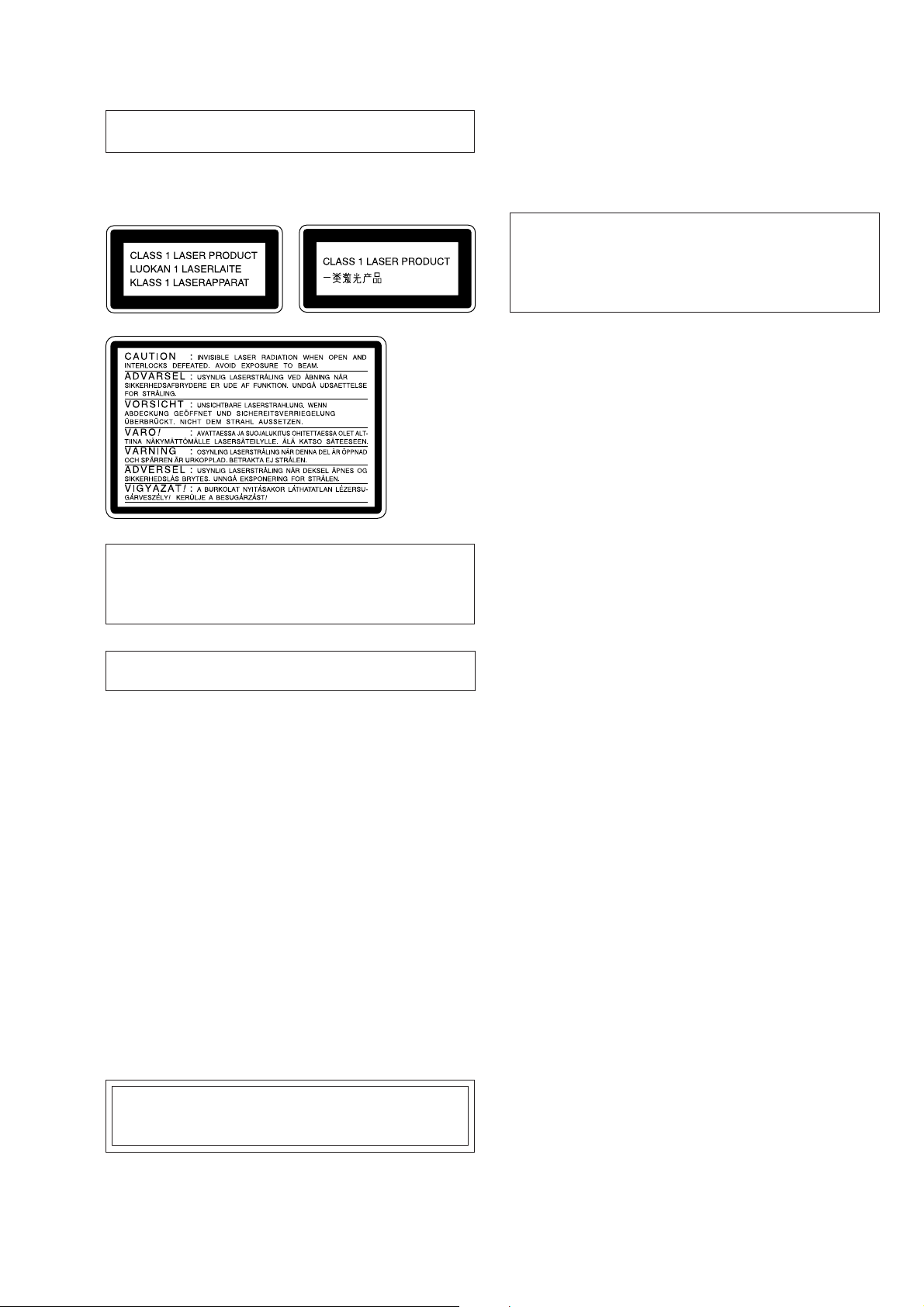
Laser component in this product is capable of emitting radiation exceeding the limit for Class 1.
This appliance is classified as a CLASS 1 LASER product.
The CLASS 1 LASER PRODUCT MARKING is located on
the rear exterior.
CAUTION
Danger of explosion if battery is incorrectly replaced.
Replace only with the same or equivalent type recommended by
the manufacturer.
Discard used batteries according to the manufacturer’s instructions.
ADVARSEL!
Lithiumbatteri-Eksplosionsfare ved fejlagtig håndtering.
Udskiftning må kun ske med batteri
af samme fabrikat og type.
Levér det brugte batteri tilbage til leverandøren.
This caution
label is located
inside the unit.
CAUTION
Use of controls or adjustments or performance of procedures
other than those specified herein may result in hazardous radiation exposure.
NOTES ON HANDLING THE OPTICAL PICK-UP
BLOCK OR BASE UNIT
The laser diode in the optical pick-up block may suffer electrostatic break-down because of the potential difference generated
by the charged electrostatic load, etc. on clothing and the human
body.
During repair, pay attention to electrostatic break-down and also
use the procedure in the printed matter which is included in the
repair parts.
The flexible board is easily damaged and should be handled with
care.
ADVARSEL
Eksplosjonsfare ved feilaktig skifte av batteri.
Benytt samme batteritype eller en tilsvarende type
anbefalt av apparatfabrikanten.
Brukte batterier kasseres i henhold til fabrikantens
instruksjoner.
VARNING
Explosionsfara vid felaktigt batteribyte.
Använd samma batterityp eller en likvärdig typ som
rekommenderas av apparattillverkaren.
Kassera använt batteri enligt gällande föreskrifter.
VAROITUS
Paristo voi räjähtää, jos se on virheellisesti asennettu.
V aihda paristo ainoastaan laite valmistajan suosittelemaan tyyppiin.
Hävitä käytetty paristo valmistajan ohjeiden mukaisesti.
Flexible Circuit Board Repairing
• Keep the temperature of the soldering iron around 270 ˚C during repairing.
• Do not touch the soldering iron on the same conductor of the
circuit board (within 3 times).
• Be careful not to apply force on the conductor when soldering
or unsoldering.
Notes on chip component replacement
• Never reuse a disconnected chip component.
• Notice that the minus side of a tantalum capacitor may be damaged by heat.
NOTES ON LASER DIODE EMISSION CHECK
The laser beam on this model is concentrated so as to be focused
on the disc reflective surface by the objective lens in the optical
pick-up block. Therefore, when checking the laser diode emission, observe from more than 30 cm away from the objective lens.
LASER DIODE AND FOCUS SEARCH OPERATION
CHECK
Carry out the “S curve check” in “CD section adjustment” and
check that the S curve waveforms is output three times.
Note:
Be sure to connect all wires (including FFC) in the MD
section before applying power or ICs may be damaged.
5
MODEL IDENTIFICATION
— BACK PANEL —
Model Part No.
AEP, UK models 4-220-708-0s
Canadian model 4-220-708-1s
Singapore model 4-220-708-3s
US model 4-220-708-4s
Chinese model 4-220-708-5s
Part No.
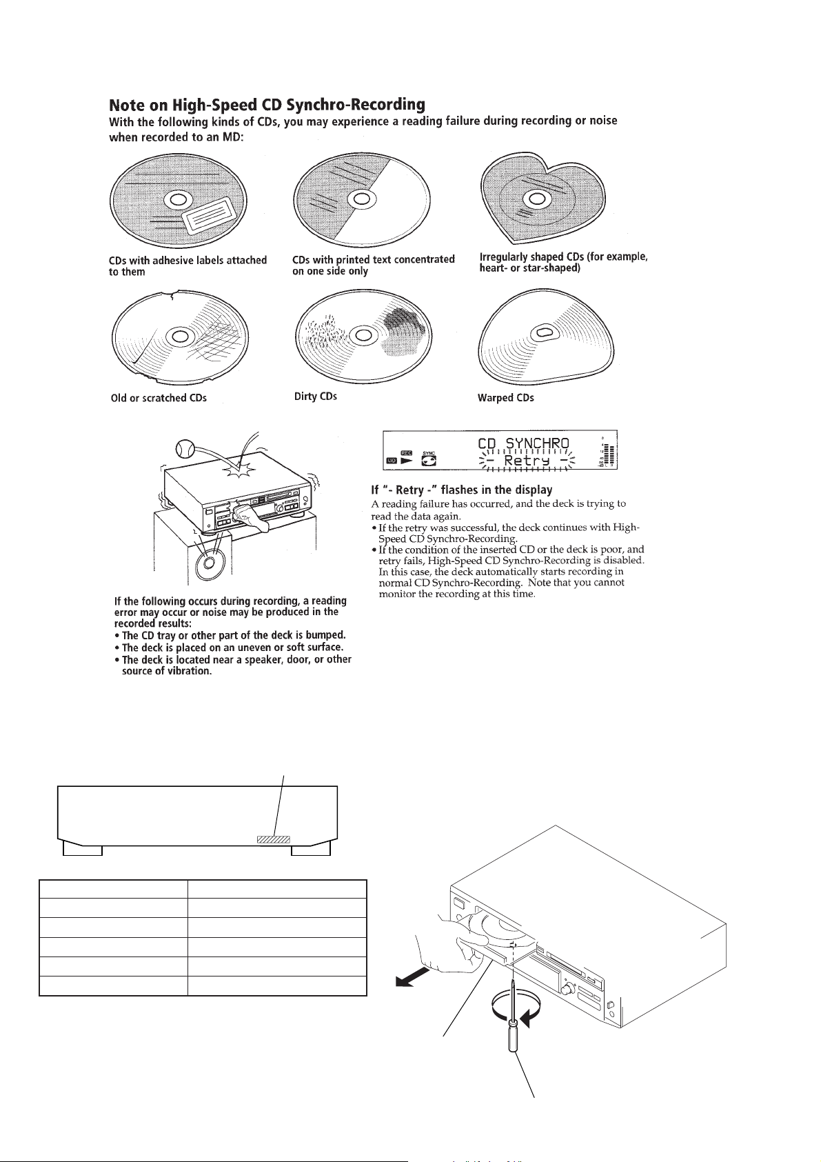
HOW T O OPEN THE DISC TABLE WHEN PO WER
SWITCH TURNS OFF.
In removing the front panel with the power not supplied, insert a
flat-blade screwdriver into a hole at the bottom of loading section
and rotate it counterclockwise. Then, draw out the disc table.
disc table
flat-blade screwdriver
6
CLEANING OBJECTIVE LENS OF OPTICAL PICK-UP IN MD
• In cleaning the objective lens of optical pick-up, move the mechanism deck by the following method.
Method:
1. Eject the disc, if loaded.
2. Disconnect the power cord from the socket to shut off the power supply.
3. Move the part C toward the direction D, while shifting the pawl in section A toward B using tweezers, etc.
4. Moving the part C freely, clean the objective lens at the position easy for cleaning.
A
B
C
D
objective lens of
optical pick-up
CLEANING OBJECTIVE LENS OF OPTICAL PICK-UP IN CD
• In cleaning the objective lens of optical pick-up, move the mechanism deck by the following method.
Method:
1. Eject the disc, if loaded.
2. Disconnect the power cord from the socket to shut off the power supply.
3. Rotating the gear in section A by your fingers clean the objective lens at the position easy for cleaning.
A
section
7
JIG FOR CHECKING BD (MD) BOARD WAVEFORM
r
3
The special jig (J-2501-149-A) is useful for checking the waveform of the BD (MD) board. The names of terminals and the checking items
to be performed are shown as follows.
GND: Ground
I+3V : For measuring IOP (Check the deterioration of the optical pick-up laser)
IOP : For measuring IOP (Check the deterioration of the optical pick-up laser)
TEO : TRK error signal (Traverse adjustment)
VC : Reference level for checking the signal
RF : RF signal (Check jitter)
Mechanism deck
RF
VC
TEO
IOP
I+3V
GND
RF
VC
TEO
5P Connector
CN110
6P connecto
1
RF
VC
for
TEO
MDM-
IOP
5
I+3V
IOP
I+3V
GND
1
VC
RF
for
TEO
IOP
MDM-5
I+3V
6
GND
8

IOP DA TA RECORDING AND DISPLAY WHEN OPTICAL PICK-UP AND NON-V OLATILE MEMORY (IC171 OF
BD (MD) BOARD) ARE REPLACED
The IOP value labeled on the optical pick-up can be recorded in the non-volatile memory . By r ecording the value, it will eliminate the need
to look at the value on the optical pick-up label. When replacing the optical pick-up or non-volatile memory (IC171 of BD (MD) board),
record the IOP value on the optical pick-up according to the following procedure.
Record Procedure:
1. Press the x (CD), [CLEAR] (CD), x (MD) and [CLEAR] (MD) buttons at the same time.
2. Press the [ AMS ] (MD) knob and x (MD) button to display “ <0> To Normal”.
3. Turn the [ AMS ] (MD) knob and when “ <5> MD Test” is displayed, press the [ AMS ] (MD) knob.
4. Turn the [ AMS ] (MD) knob to display “[Service]”, and press the [YES] button.
5. Turn the [ AMS ] (MD) knob to display “Iop Write” (C28), and press the [YES] button.
6. The display becomes “Ref=@@@.@” (@ is an arbitrary number) and the numbers which can be changed will blink.
7. Input the IOP value written on the optical pick-up label.
To select the number : Turn the [ AMS ] (MD) knob.
To select the digit : Press the [ AMS ] (MD) knob.
8. When the [YES] button is pressed, the display becomes “Measu=@@@.@” (@ is an arbitrary number).
9. As the adjustment results are recorded for the 6 value. Leave it as it is and press the [YES] button.
10. “Complete!” will be displayed momentarily. The value will be recorded in the non-volatile memory and the display will become “Iop
Write”.
11. Press the ?/1 button to turn the power OFF.
Display Procedure:
1. Press the x (CD), [CLEAR] (CD), x (MD) and [CLEAR] (MD) buttons at the same time.
2. Press the [ AMS ] (MD) knob and x (MD) button to display “ <0> To Normal”.
3. Turn the [ AMS ] (MD) knob and when “ <5> MD Test” is displayed, press the [ AMS ] (MD) knob.
4. Turn the [ AMS ] (MD) knob to display “[Service]”, and press the [YES] button.
5. Turn the [ AMS ] (MD) knob to display “Iop Read” (C27).
6. “@@.@/##.#” is displayed and the recorded contents are displayed.
@@.@: indicates the IOP value on the optical pick-up label.
##.# : indicates the IOP value after adjustment
7. To end, press the
OFF.
lL
lL
lL
lL
lL
lL
lL
lL
lL
lL
[ AMS ] (MD) knob or [MENU/NO] button to display “Iop Read”. Press the ?/1 b utton to turn the power
lL
lL
lL
9

CHECKS PRIOR TO PARTS REPLACEMENT AND ADJUSTMENTS IN MD
Before performing repairs, perform the following checks to determine the faulty locations up to a certain extent.
Details of the procedures are described in “5 Electrical Adjustments”.
Laser power check
(6-2 : See page 32)
Traverse check
(6-3 : See page 32)
Focus bias check
(6-4 : See page 33)
C PLAY check
(6-5 : See page 33)
Self-recording/playback
check
(6-6 : See page 33)
Temperature
compensation
offset check
(6-1 : See page 32)
Criteria for Determination
(Unsatisfactory if specified value is not satisfied)
• 0.9 mW power
Specified value : 0.80 to 0.96 mW
• 8.4 mW power
Specified value : 8.2 to 8.6 mW
Iop (at 8.4mW)
• Labeled on the optical pick-up
Iop value ± 10mA
• Travers e waveform
Specified value : Below 10% offset
• Error rate check
Specified value : For points a, b, and c
C1 error : About 200
AD error : below 2
• Error rate check
Specified value:
a. When using test disc (MDW-74/AU-1)
C1 error : Below 80
AD error : Below 2
b. When using check disc (TDYS-1)
C1 error : Below 50
• CPLAY error rate check
Specified value:
C1 error : Below 80
AD error : Below 2
• Unsatisfactory if displayed as T=@@ (##) [NG”
NG
(@@, ## are both arbitrary numbers)
• Clean the optical pick-up
• Adjust again
• Replace the optical pick-up
• Replace the optical pick-up
• Replace the optical pick-up
• Replace the optical pick-up
• Replace the optical pick-up
If always unsatisfactory:
• Replace the overwrite head
• Check for disconnection of the circuits around the
overwrite head
If occasionally unsatisfactory:
• Check if the overwrite head is distorted
• Check the mechanism around the sled
• Check for disconnection of the circuits around
D101 (BD (MD) board)
• Check the signals around IC101, IC121, CN102,
CN103 (BD (MD) board)
Measure if unsatisfactory:
Note:
The criteria for determination above is intended merely to determine if satisfactory or not, and does not serve as the specified value for adjustments.
When performing adjustments, use the specified values for adjustments.
10
SERVICE MODE
This set provides various modes for the service.
Enter the service mode through the procedure given below, and select the desired mode.
Procedure:
1. Press the x (CD), [CLEAR] (CD), x (MD) and [CLEAR] (MD) buttons at the same time.
2. Press the [ AMS ] (MD) knob and x (MD) button to display “ <0> To Normal”.
3. At this time, rotating the [ AMS ] (MD) knob can select all modes. For the contents of mode, see the following table.
4. To e xit from the service mode, press the x (MD) button and [ AMS ] (MD) knob simultaneously to display “<0> T o Normal”,
then press the [ AMS ] (MD) knob. If this operation failed, press the ?/1 button to turn the power OFF.
Contents of test mode
No. Display Function
0 <0> To Normal Exit from test mode
1 <1> Virsion Microcomputer V irsion display
2 <2> FLD FL display test
3 <3> Key/Jog Key/Jog input test
4 <4> CD Test CD all sorts test
5 0> AGING CD aging mode
6 1> COMMAND Command transfer menu
7 2> ERROR C1, C2 error display
8 3> SPEED X1 Disc speed selection
9 4> ISRC ISRC display
10 5> CHECK8 Check 8 cm display
11 6> AUTO G Auto gain display
12 7> HENSHIN Decentiering display
13 8> PORT Port selection
14 9> AMS AMS display
15 A> TRK ON TRK ON/OFF display
16 <5> MD Test MD all sorts test
17 <6> Retry & TOC MD TOC off & Retry test
18 <7> Initial All reset
19 <8> Special Command, Sircs test
20 <9> Dump Microcomputer Dump mode
lL
lL
lL
lL
11
Microcomputer Ver sion Display
Procedure:
1. Enter the service mode, then rotate [ AMS ] (MD) knob to display “<1> Version”, and press the [ AMS ] (MD).
lL
lL
2. The CD and MD microcomputer versions are displayed on the upper line and lower line respectively.
3. To exit from the mode, press the x (MD) button and [ AMS ] (MD) knob simultaneously.
lL
FL Display Test
Procedure:
1. Enter the service mode, then rotate [ AMS ] (MD) knob to display “<2> FLD”, and press the [ AMS ] (MD).
2. The fluorescent display tube turns ON fully. Each time the [ AMS ] (MD) knob is pressed, the display changes such as
lL
lL
lL
[Full ON] t [Partial ON] t [Selected menu].
3. To exit from the mode, press the x (MD) button and [ AMS ] (MD) knob simultaneously.
lL
Key/Jog Input Test
Procedure:
1. Enter the service mode, then rotate [ AMS ] (MD) knob to display “<3> Key/Jog”, and press the [ AMS ] (MD).
lL
lL
2. KEY=29 is displayed, and each time a key is pressed, the corresponding pictograph goes off and numeric value is counted down.
When all keys were pressed, KEY=0 is displayed.
Correspondence between KEY and pictorial display
KEY Pictorial display KEY Pictorial display KEY Pictorial display
l AMS L
(CD) HIGH
x (CD)
X (CD) X (upper) CLEAR (MD)
[DISC] (upper) m (CD) (CD)
[CD]
l AMS L
(MD) NORMAL
[DISC] (under)
[TRACK] (under)
H (CD) H (upper) TIME MD MONO x (MD)
?/1 [OVER]
PLAY MODE
CD
OPT INPUT COAX H (MD) H (under)
PLAY MODE
MD
L.SYNC X (MD) X (under)
CD SYNCHRO
CD SYNCHRO
A
OPNE/CLOSE
X 4
SYNC
[MD]
TIME CD CD DISPLAY ANALOG M (MD) (MD)
CLEAR (CD)
[TRACK]
(upper)
m (MD) (MD) REC z (MD) [REC]
REC-IT (CD) REC IT YES TOC A EJECT
M (CD) (CD) MENU/NO [EDIT]
Software Reset
Procedure:
1. Enter the service mode, then rotate [ AMS ] (MD) knob to display “<6> Initial”, and press the [ AMS ] (MD).
lL
lL
2. The microcomputer resets the software, and the power is turned off.
12
RETRY CAUSE DISPLAY MODE IN MD
• In this test mode, the causes for retry of the unit during recording can be displayed on the fluorescent indicator tube. During playback,
the “track mode” for obtaining track information will be set.
This is useful for locating the faulty part of the unit.
• The following will be displayed :
During recording and stop: Retry cause, number of retries, and number of retry errors.
During playback : Information such as type of disc played, part played, copyright.
These are displayed in hexadecimal.
Procedure:
1. Load a recordable disc whose contents can be erased into the unit.
2. Press the [MENU/NO] button. When “Edit Menu” is displayed on the fluorescent indicator tube, turn the [ AMS ] (MD) knob
to display “All Erase?”.
3. Press the [YES] button. (Or press the [ AMS ] (MD) knob)
4. When “All Erase??” is displayed on the fluorescent indicator tube, the music calendar number blinks.
5. Press the [YES] button to display “Complete!!”, and press the x (MD) button immediately . Wait for about 15 seconds while pressing
the button. (The [ AMS ] (MD) knob can be pressed instead of the [YES] button for the same results)
6. When the “TOC” displayed on the fluorescent display tube goes off, release th x (MD) button.
7. Press the [REC ] button to start recording. Then press the X (MD) button and start recording.
8. To check the “track mode”, press the H (MD) button to start play.
9. To release the test mode , press the ?/1 button, and turn OFF the po wer. When “TOC” disappears, disconnect the power plug from the
outlet.
lL
z
lL
lL
Fig. 1 Reading the Test Mode Display
(During recording and stop)
RTs@@c##e
Fluorescent indicator tube display
@@ : Cause of retry
## : Number of retries
: Number of retry errors
**
Reading the Retry Cause Display
Higher Bits Lower Bits
Hexadecimal
Bit
Binary
84218421
b7 b6 b5 b4 b3 b2 b1 b0
00000001
00000010
00000100
00001000
00010000
00100000
01000000
10000000
**
Hexa-
decimal
01
02
04
08
10
20
40
80
Cause of Retry
shock
ader5
Discontinuous address
DIN unlock
FCS incorrect
IVR rec error
CLV unlock
Access fault
Fig. 2 Reading the Test Mode Display
(During playback)
@@ ###
Fluorescent indicator tube display
@@: Parts No. (name of area named on TOC)
## : Cluster
: Sector
**
$$ : Track mode (Track information such as copy-
right information of each part)
When track jump (shock) is detected
When ADER was counted more than five times
continuously
When ADIP address is not continuous
When DIN unlock is detected
When not in focus
When ABCD signal level exceeds the specified range
When CLV is unlocked
When access operation is not performed normally
Address
Occurring conditions
**
$$
Reading the Display:
Convert the hexadecimal display into binary display. If more than two causes, they will be added.
Example
When 42 is displayed:
Higher bit: 4 = 0100 t b6
Lower bit : 2 = 0010 t b1
In this case, the retry cause is combined of “CLV unlock” and “ader5”.
When A2 is displayed:
Higher bit: A = 1010 t b7 + b5
Lower bit : 2 = 0010 t b1
The retry cause in this case is combined of “access fault”, “IVR rec error”, and “ader5”.
13
Reading the Retry Cause Display
Higher Bits
Hexadecimal
Bit
Binary
Reading the Display:
Convert the hexadecimal display into binary display. If more than two causes, they will be added.
Example When 84 is displayed:
Higher bit: 8 = 1000 t b7
Lower bit : 4 = 0100 t b2
In this case, as b2 and b7 are 1 and others are 0, it can be determined that the retry cause is combined of “emphasis OFF”, “monaural”,
“original”, “copyright exists”, and “write allowed”.
Example When 07 is displayed:
Higher bit: 0 = 1000 t All 0
Lower bit : 7 = 0111 t b0 + b1 + b2
In this case, as b0, b1, and b2 are 1 and others are 0, it can be determined that the retry cause is combined of “emphasis ON”, “stereo”,
“original”, “copyright exists”, and “write prohibited”.
84218421
b7 b6 b5 b4 b3 b2 b1 b0
00000001
00000010
00000100
00001000
00010000
00100000
01000000
10000000
Lower Bits
Hexa-
decimal
01
02
04
08
10
20
40
80
When 0
Emphasis OFF
Monaural
This is 2-bit display. Normally 01.
01:Normal audio. Others:Invalid
Audio (Normal)
Original
Copyright
Write prohibited
Details
When 1
Emphasis ON
Stereo
Invalid
Digital copy
No copyright
Write allowed
Hexadecimal t Binary Conversion Table
Hexadecimal Binary Hexadecimal Binary
0 0000 8 1000
1 0001 9 1001
2 0010 A 1010
3 0011 B 1011
4 0100 C 1100
5 0101 D 1101
6 0110 E 1110
7 0111 F 1111
14

CD-TEXT TEST DISC
This unit is able to display the test data (character information) written in the CD on its fluorescent indicator tube.
The CD-TEXT TEST DISC (TGCS-313:4-989-366-01) is used for checking the display.
To check, perform the following procedure.
Checking Method:
1. Turn ON the power, set the disc to the disc table with the “test disc” label facing up, and chuck the disc.
2. Press the H (CD) button and play back the disc.
3. The following will be displayed on the fluorescent indicator tube.
Display : 1KHZ
4. Rotating [ AMS ] (CD) knob, select the track. The text data of each track will be displayed.
For details of the displayed contents for each track, refer to “Table 1 : CD-TEXT TEST DISC TEXT Data Contents” and “Table 2 : CDTEXT TEST DISC Recorded Contents and Display”.
Restrictions in CD-TEXT Display
In this unit, some special characters will not be displayed properly. These will be displayed as a space or a character resembling it. For
details, refer to “Table 2 : CD-TEXT DISC Recorded Contents and Display”.
Table 1 : CD-TEXT TEST DISC TEXT Data Contents (TRACKS No. 1 to 41:Normal Characters)
TRACK
lL
No.
1 1kHz/0dB/L&R 22 1kHz/-90dB/L&R
2 20Hz/0dB/L&R 23 Infinity Zero w/o emphasis//L&R
3 40Hz/0dB/L&R 24 Infinity Zero with emphasis//L&R
4 100Hz/0dB/L&R 25 400Hz+7kHz(4:1)/0dB/L&R
5 200Hz/0dB/L&R 26 400Hz+7kHz(4:1)/-10dB/L&R
6 500Hz/0dB/L&R 27 19kHz+20kHz(1:1)/0dB/L&R
7 1kHz/0dB/L&R 28 19kHz+20kHz(1:1)/-10dB/L&R
8 5kHz/0dB/L&R 29 100Hz/0dB/L*
9 7kHz/0dB/L&R 30 1kHz/0dB/L*
10 10kHz/0dB/L&R 31 10kHz/0dB/L*
11 16kHz/0dB/L&R 32 20kHz/0dB/L*
12 18kHz/0dB/L&R 33 100Hz/0dB/R*
13 20kHz/0dB/L&R 34 1kHz/0dB/R*
14 1kHz/0dB/L&R 35 10kHz/0dB/R*
15 1kHz/-1dB/L&R 36 20kHz/0dB/R*
16 1kHz/-3dB/L&R 37 100Hz Squer Wave//L&R
17 1kHz/-6dB/L&R 38 1kHz Squer Wave//L&R
18 1kHz/-10dB/L&R 39 1kHz w/emphasis/-0.37dB/L&R
19 1kHz/-20dB/L&R 40 5kHz w/emphasis/-4.53dB/L&R
20 1kHz/-60dB/L&R 41 16kHz w/emphasis/-9.04dB/L&R
21 1kHz/-80dB/L&R
0DB
Displayed Contents
TRACK
No.
Displayed Contents
Note: The contents of Track No. 1 to 41 are the same as those of the current TEST DISC-their titles are displayed.
15
Table 2: CD-TEXT TEST DISC Recorded Contents and Display
(In this unit, some special characters cannot be displayed. This is not a fault)
TRACK
No.
42
43
44
45
46
47
48
49
50
51
52
53
54
55
56
57
58
59
60
61
62
63
64
65
66
67
to
99
Recorded contents
! ” # $% & ´ (21h to 27h)1kHz 0dB L&R
( ) + , – . / (28h to 2Fh)
*
01234567 (30h to 37h)
8 9 : ; < = > ? (38h to 3Fh)
@A B C D E F G (40h to 47h)
H I J K L MNO (48h to 4Fh)
P QR S T U VW (50h to 57h)
X Y Z [ ¥ ] ^ _ (58h to 5Fh)
a b c d e f g (60h to 67h)
′
h i j k l m n o (68h to 6Fh)
p q r s t u v w (70h to 77h)
xyz{ I }
~
(78h to 7Fh)
i¢£¤¥ § (A0h to A7h) 8859-1
¬
C ª
•±23
1
†
º ¿ (B8h to BFh)
–
PR
µ¶ • (B0h to B7h)
′
14123
(A8h to AFh)
4
АБВГДЕЖЗ (C0h to C7h)
ИЙКЛМНОП (C8h to CFh)
D СТУФХЦ
ШЩЪЫЬY
˙
(D0h to D7h)
ß (D8h to DFh)
абвгдежз (E0h to E7h)
ийклмноп (E8h to FFh)
∂ стуфхц÷ (F0h to F7h)
шщъыьy я (F8h to FFh)
´
No.66
No.67
to
No.99
Display
T All the same
T All the same
T All the same
T All the same
T All the same
T All the same
T All the same
T All the same
T All the same
T All the same
T All the same
T All the same
(A0h to A7h) 8859-1
(A8h to AFh)
(B0h to B7h)
(B8h to BFh)
AAAAAA C (C0h to C7h)
E E E E I I I I (C8h to CFh)
DNOOOOO (D0h to D7h)
O UUU U Y (D8h to DFh)
a a a a a a c (E0h to E7h)
eeeeiiii (E8h to EFh)
dnooooo (F0h to F7h)
o u u u u y y (F8h to FFh)
T All the same
T All the same
to
T All the same
16
SECTION 2
GENERAL
Front view Rear view
1 2 3 4 5 678 90 qa qs qd
qfqgqhqj
1 LINE (ANALOG) IN jack
2 LINE (ANALOG) OUT jack
3 DIGITAL OPTICAL IN terminal
4 VOLTAGE SELECTOR switch (singapore model only)
5 AC power cord
wa
qlw;
qk
ws
ed 12 3 4 5
1 ?/1 (power) switch
2 REC-IT button
3 CD disc tray
4 Display window
5 A OPEN/CLOSE button
6 CD SYNC NORMAL button
7 CD SYNC HIGH button
8 MENU/NO button
9 MD insertion slot
0 YES button
qa A EJECT button
qs PHONE LEVEL control
qd PHONES jack
qf REC z button
qg x button
qh X button
qj H button
qk m/M button
ql AMS control
w; CLEAR button
wa MD TIME button
ws MD PLAY MODE button
wd INPUT button
wf DISPLAY button
wg CD PLAY MODE button
wh CD TIME button
wj CLEAR button
wk AMS control
wl x button
e; X button
ea H button
es m/M button
ed Remote sensor
wkwlea
e;es
wj
wfwh
wdwg
17
SECTION 3
)
DISASSEMBLY
Note: Follow the disassembly procedure in the numerical order given.
LOADING PANEL
In removing the front panel with the power not supplied,
insert a flat-blade screwdriver into a hole at the bottom of loading section and rotate it counterclockwise.
Then, draw out the disc table and remove the loading panel.
2
1
3
Remove the loading panel
to direction of the arrow.
COVER, FRONT PANEL SECTION
2
cover
7
two claws
5
three screws
(BVTT3
×
6)
6
lug
1
two screws
(case3 TP2)
CD MECHANISM DECK SECTION (Page 19)
MD MECHANISM DECK SECTION (Page 21)
MAIN BOARD (Page 23)
1
two screws
(case3 TP2)
1
two screws
(case3 TP2)
3
wire (flat type) (19 core
(CN604)
8
front panel section
18
5
six screws
(BVTT3
4
connector
(CN451)
7
two claws
×
6)
CD MECHANISM DECK SECTION
(CDM14H-5TBD26B)
3
lead (with connector)
5
Push the disc table.
4
three screws
(BVTT3
×
6)
A
B
4
three screws
(BVTT3
×
6)
6
Pulling the front panel in the direction of the arrow A
a little, remove the mechanism deck (CDM14H-5TBD26B)
in the direction of the arrow
Note: Don’t pull the front panel in the direction of
the arrow
A
by force.
wire (flat type) (29 core)
1
(CN501)
2
connector
(CN502)
B
.
CHASSIS (MD)
1
Rotate the cam counterclockwise
with a flat-blade screwdriver.
cam
4
Remove the chassis (MD)
to direction of the arrow
A
3
.
yoke bracket
A
2
Pull out the disc table.
19
CD BASE UNIT (BU-5TBD26B)
)
1
two screws
(PTPWHM2.6)
3
two compression springs (932)
1
two screws
(PTPWHM2.6)
2
CD base unit (BU-5TBD26B)
3
two compression springs (932)
4
chassis (MD)
BD (CD) BOARD
Note: When routing the lead wires of spindle motor,
pass them through a slot in the BD (CD) board,
then solder to the motor. Then, secure the lead wires
to the IC191 with an adhesive sheet so as not to be loose,
as shown in the figure.
adhesive sheet
motor leads
IC191
spindle motor
2
Remove two solders
of spindle motor leads.
4
screw
(BVTP2.6
3
two screws
(P2
×
8)
×
3)
5
1
wire (flat type) (16 core
(CN102)
BD (CD) board
20
MD MECHANISM DECK SECTION
(MDM-5X2B)
6
Remove the MD
mechanism deck
(MDM-5X2B) to
direction of the arrow.
3
screw
(BVTT3
×
6)
4
lug
5
four step screws
(BVTTWH M3)
1
wire (flat type) (27 core)
(CN602)
1
wire (flat type) (23 core)
(CN601)
2
connector
(CN603)
SLIDER (CAM)
4
bracket (Guide L)
1
two screws (P2.6 × 6)
2
3
leaf spring
lug
7
slider (Cam)
• Note for Installation of Slider A (Cam)
Set the shaft of Cam gear to
be at the position in the figure.
Set the shaft of Lever (O/C) to
be at the position in the figure.
5
two screws (P2.6 × 6)
6
bracket (Guide R)
21
MD BASE UNIT (MBU-5X2B), BD (MD) BOARD
)
5
flexible board
(CN104)
6
flexible board
(CN101)
1
three screws
(P2.6
2
base unit (MBU-5X2B)
×
6)
7
BD (MD) board
SW BOARD, LOADING MOTOR (M203)
3
two screws
(PWH1.7
6
2
SW board
gear B
×
4)
4
screw (M1.7 × 4)
3
Remove the solder (Seven portion).
1
screw (PTPWH M2.6 × 6
4
loading motor (M203)
22
5
three screws (BTP2.6 × 6)
MAIN BOARD
)
1
wire (flat type) (29 core)
(CN501)
1
wire (flat type) (27 core)
(CN602)
2
connector
(CN502)
3
screw
(BVTT3
2
three connectors
(CN603, 901, 902)
×
6)
1
wire (flat type) (19 core)
(CN604)
2
connector
(CN451)
3
screw
(BVTT3
×
6)
6
MAIN board
4
two screws
(BVTP3
×
8
5
1
wire (flat type) (23 core)
(CN601)
two PC board holders
MEASURE AGAINST HEAT FROM HEAT SINK
When connecting the cable from TRANS board (CN101) to MAIN board (CN902),
cross it with the cable between SW board (CN601) and MAIN board (CN603), as shown in the figure.
TRANS board
CN101
CN601
SW board
heat sink
CN902
CN603
#
MAIN board
23
SECTION 4
TEST MODE
MD SECITON
Note: MD always plays double speed.
1. PRECAUTIONS FOR USE OF TEST MODE
• As loading related operations will be performed regardless of the test mode operations being performed, be sure to check that the disc
is stopped before setting and removing it.
Even if the [ EJECT] button is pressed while the disc is rotating during continuous playback, continuous recording, etc., the disc will
not stop rotating.
Therefore, it will be ejected while rotating.
Be sure to press the [ EJECT] button after pressing the [MENU/NO] button and the rotation of disc is stopped.
1-1. Recording laser emission mode and operating buttons
• Continuous recording mode (CREC MODE)
• Laser power check mode (LDPWR CHECK)
• Laser power adjustment mode (LDPWR ADJUS)
• Traverse (MO) check (EF MO CHECK)
• Traverse (MO) adjustment (EF MO ADJUS)
• When pressing the [REC ] button.
2. SETTING THE TEST MODE
The following are two methods of entering the test mode.
Procedure 1: Press the x (CD), [CLEAR] (CD), x (MD) and [CLEAR] (MD) buttons at the same time.
Procedure 2: While pressing the [ AMS ] (MD) knob, connect the power plug to the outlet and release the [ AMS ]
A
A
z
Press the [ AMS ] (MD) knob and x (MD) button to display “ < 0 > To Normal”.
Turn the [ AMS ] (MD) knob and when “ < 5 > MD Test” is displayed, press the [ AMS ] (MD) knob.
When the test mode is set, “[Check]” will be displayed. Turn the [ AMS ] (MD) knob switches between the
following four groups; ···Tt [Check] Tt [Adjust] Tt [Service] Tt [Develop] Tt ···.
(MD) knob.
When the test mode is set, “TEMP CHECK” will be displayed. By setting the test mode using this method, only the “Check”
group of method 1 can be executed.
lL
lL
lL
lL
lL
lL
3. RELEASING THE TEST MODE
Press the ?/1 button to turn the power OFF. (with initialize)
4. BASIC OPERATIONS OF THE TEST MODE
All operations are performed using the [ AMS ] (MD) knob, [YES] button, and [MENU/NO] button.
The functions of these buttons are as follows.
Function name Function
l AMS L knob (MD) Changes parameters and modes
YES button Proceeds onto the next step. Finalizes input.
MENU/NO button Returns to previous step. Stops operations.
lL
24

5. SELECTING THE TEST MODE
There are 31 types of test modes as shown below. The groups can be switched by turning the [ AMS ] (MD) knob. After selecting
the group to be used, press the [YES] button. After setting a certain group, turn the [ AMS ] (MD) knob switches betw een these
lL
modes.
Refer to “Group” in the table for details can be selected.
All items used for servicing can be treated using group S. So be carefully not to enter other groups by mistake.
lL
Display
TEMP CHECK
LDPWR CHECK
EF MO CHECK
EF CD CHECK
FBIAS CHECK
Scurve CHECK
VERIFYMODE
DETRK CHECK
TEMP ADJUS
LDPWR ADJUS
EF MO ADJUS
EF CD ADJUS
FBIAS ADJUS
EEP MODE
MANUAL CMD
SVDATA READ
ERR DP MODE
SLED MOVE
ACCESS MODE
0920 CHECK
HEAD ADJUST
CPLAY 1MODE
CREC 1MODE
ADJ CLEAR
AG Set (MO)
AG Set (CD)
Iop Read
Iop Write
INFORMATION
CPLAY MODE
CREC MODE
No.
C01
C02
C03
C04
C05
C06
C07
C08
C09
C10
C11
C12
C13
C14
C15
C16
C17
C18
C19
C20
C21
C22
C23
C24
C25
C26
C27
C28
C29
C30
C31
Contents
Temperature compensation offset check
Laser power check
Traverse (MO) check
Traverse (CD) check
Focus bias check
S letter check
Non-volatile memory check
Detrack check
Temperature compensation offset adjustment
Laser power adjustment
Traverse (MO) adjustment
Traverse (CD) adjustment
Focus bias adjustment
Non-volatile memory control
Command transmission
Status display
Error history display, clear
Sled check
Access check
Outermost circumference check
Head position check
Same functions as CPLAY MODE (Not used in servicing)
Same functions as CREC MODE (Not used in servicing)
Initialization of non-volatile memory of adjustment value
Auto gain output level adjustment (MO)
Auto gain output level adjustment (CD)
IOP data display
IOP data write
Microprocessing version display
Continuous playback mode
Continuous recording mode
Mark
(X)
(X)
(X)
(X) (!)
(X)
(X)
(X)
(X)
(X)
(X)
(X)
(X)
Group (*)
C: Check
S: Service
Group (*)
CS
CS
CS
CS
CS
C
C
C
AS
AS
AS
AS
AS
D
D
D
S
D
D
D
D
D
D
AS
AS
AS
CS
AS
CS
CASD
CASD
A: Adjust
D: Develop
• For details of each adjustment mode, refer to “5. Electrical Adjustments”.
For details of “ERR DP MODE”, refer to “Self-Diagnosis Function” on page 2.
• If a different mode has been selected by mistake, press the
[MENU/NO] button to release that mode.
• Modes with (X) in the Mark column are not used for servicing and therefore are not described in detail. If these modes are set accidentally, press the [MENU/NO] button to release the mode immediately. Be especially careful not to set the modes with (!) as they will
overwrite the non-volatile memory and reset it, and as a result, the unit will not operate normally.
25
5-1. Operating the Continuous Playback Mode
1. Entering the continuous playback mode
(1) Set the disc in the unit. (Whichever recordable discs or discs for playback only are available)
(2) Turn the [ AMS ] (MD) knob and display “CPLAY MODE” (C30).
lL
(3) Press the [YES] button to change the display to “CPLAY MID”.
(4) When access completes, the display changes to “C = AD = ”.
Note: The numbers “ ” displayed show you error rates and ADER.
2. Changing the parts to be played back
(1) Press the [YES] button during continuous playback to change the display as below.
“CPLAY MID” t “CPLAY OUT” t “CPLAY IN”
When pressed another time, the parts to be played back can be moved.
(2) When access completes, the display changes to “C = AD = ”.
Note: The numbers “ ” displayed show you error rates and ADER.
3. Ending the continuous playback mode
(1) Press the [MENU/NO] button. The display will change to “CPLAY MODE”.
(2) Press the [ EJECT] button and take out the disc.
Note: The playback start addresses for IN, MID, and OUT are as follows.
A
IN 40h cluster
MID 300h cluster
OUT 700h cluster
5-2. Operating the Continuous Recording Mode (Use only when performing self-recording/palyback check)
1. Entering the continuous recording mode
(1) Set a recordable disc in the unit.
(2) Turn the [ AMS ] (MD) knob and display “CREC MODE”.
lL
(3) Press the [YES] button to change the display to “CREC MID” (C31).
(4) When access completes, the display changes to “CREC ( ” and “ REC ” lights up.
Note: The numbers “ ” displayed shows you the recording position addresses.
2. Changing the parts to be recorded
(1) When the [YES] button is pressed during continuous recording, the display changes as below.
“CREC MID” t “CREC OUT” t “CREC IN”
When pressed another time, the parts to be recorded can be changed. “ REC ” goes off.
(2) When access completes, the display changes to “CREC (
Note: The numbers “ ” displayed shows you the recording position addresses.
” and “ REC ” lights up.
3. Ending the continuous recording mode
(1) Press the
(2) Press the [ EJECT] button and take out the disc.
Note 1: The recording start addresses for IN, MID, and OUT are as follows.
[MENU/NO] button. The display changes to “CREC MODE” and “ REC
A
” goes off.
IN 40h cluster
MID 300h cluster
OUT 700h cluster
Note 2: The [MENU/NO] button can be used to stop recording anytime.
Note 3: Do not perform continuous recording for long periods of time above 5 minutes.
Note 4: During continuous recording, be careful not to apply vibration.
5-3. Non-Volatile Memory Mode (EEP MODE)
This mode reads and writes the contents of the non-volatile memory.
It is not used in servicing. If the unit entered this mode accidentally, press the [MENU/NO] button immediately to release it.
26
6. FUNCTIONS OF OTHER BUTTONS
Function
H (MD)
x (MD)
M (MD)
m (MD)
CLEAR (MD)
PLAY MODE (MD)
DISPLAY
A EJECT
?/1
Sets continuous playback when pressed in the STOP state. When pressed during continuous playback, the tracking servo
turns ON/OFF.
Stops continuous playback and continuous recording.
The sled moves to the outer circumference only when this is pressed.
The sled moves to the inner circumference only when this is pressed.
Switches between the pit and groove modes when pressed.
Switches the spindle servo mode (CLV-S y CLV-A).
Switches the displayed contents each time the button is pressed
Ejects the disc
Releases the test mode
Contents
7. TEST MODE DISPLAYS
Each time the [DISPLAY] button is pressed, the display changes in the following order.
1. Mode display
Displays “TEMP ADJUS”, “CPLAYMODE”, etc.
2. Error rate display
Displays the error rate in the following way.
C = ssss AD = ss
C = Indicates the C1 error.
AD = Indicates ADER.
3. Address display
The address is displayed as follows. (MO: recordable disc, CD: playback only disc)
Press the [CLEAR] (MD) button to switches between the groove display and pit display.
h = ssss s = ssss (MO pit and CD)
h = ssss a = ssss (MO groove)
h = Indicates the header address.
s = Indicates the SUBQ address.
a = Indicates the ADIP address.
Mode display
Error rate display
Address display
Auto gain display
(Not used in servicing)
Detrack check display
(Not used in servicing)
IVR display
(Not used in servicing)
Note: “–” is displayed when servo is not imposed.
4. Auto gain display (Not used in servicing)
The auto gain is displayed as follows.
AG = ss/ss[ ss
5. Detrack check display (Not used in servicing)
The detrack is displayed as follows.
ADR = sssssss
6. IVR display (Not used in servicing)
The IVR is displayed as follows.
[ss][ss][ss
27
 Loading...