

Page 1

MVS -8000X/MVS-7000X
QUICK SETUP GUIDE
Revision 1.3
Copyright © 2012 Sony Electronics Inc. All rights Reserved.
All features, specifications and procedures subject to change without notice.
pg. 1
Page 2

Table of Contents
Section 1: Overview ..................................................................................................................................... 5
What is the MVS System? ........................................................................................................................ 5
After your Installation… ........................................................................................................................... 8
Installation Check-Out........................................................................................................................... 8
Operator Training .................................................................................................................................. 9
Section 2: Engineering Quick Start (Hardware) ......................................................................................... 10
Where to turn for help ........................................................................................................................... 10
What are all these boxes? ...................................................................................................................... 10
Unpacking the boxes .............................................................................................................................. 11
Rack Mounting ....................................................................................................................................... 12
Power Requirements & Environmental ................................................................................................. 12
Where do the components go? .............................................................................................................. 12
Group and Unit ID settings ..................................................................................................................... 13
Wiring ..................................................................................................................................................... 14
LANs .................................................................................................................................................... 14
SWITCHER CHASSIS (MVS-7000X only) .................................................................................................. 16
Video Inputs ........................................................................................................................................ 17
Video Outputs ..................................................................................................................................... 17
Reference ............................................................................................................................................ 17
Format Converter ................................................................................................................................ 18
Multi-Viewer ....................................................................................................................................... 18
DME Inputs and Outputs..................................................................................................................... 18
SWITCHER CHASSIS (MVS-8000X only) .................................................................................................. 20
Video Inputs ........................................................................................................................................ 21
Video Outputs ..................................................................................................................................... 21
MVS-8000X Dedicated M/E Outputs .................................................................................................. 22
Reference ............................................................................................................................................ 22
Format Converters .............................................................................................................................. 22
Multi-Viewer ....................................................................................................................................... 23
DME Inputs and Outputs..................................................................................................................... 23
Control Panel .......................................................................................................................................... 25
Panel Type ........................................................................................................................................... 25
Connecting the Panel .......................................................................................................................... 27
pg. 2
Page 3

External Adapters ................................................................................................................................ 27
USB/Memory Stick .............................................................................................................................. 28
Other Control Panel connections ........................................................................................................ 28
DME Chassis ............................................................................................................................................ 29
Device Control Unit (DCU) ...................................................................................................................... 29
Parallel Tally ........................................................................................................................................ 30
Serial Tally ........................................................................................................................................... 30
Aux Bus Remotes .................................................................................................................................... 31
After the Install ....................................................................................................................................... 32
Routine Maintenance ......................................................................................................................... 32
Other tips to keep your new switcher working well….. ...................................................................... 32
Start-up ................................................................................................................................................... 33
Section 3: Engineering Quick Start (Software) .......................................................................................... 34
Menu Overview ...................................................................................................................................... 34
Menu Page Numbers .......................................................................................................................... 36
Network Config ....................................................................................................................................... 37
LAN Diagnostics ...................................................................................................................................... 40
Errors ....................................................................................................................................................... 40
System Config ......................................................................................................................................... 42
Signal Format ......................................................................................................................................... 44
Format Converters .................................................................................................................................. 48
Software Versions .................................................................................................................................. 49
MVS-7000X FlexConfig ........................................................................................................................... 50
A Note on using 8 Keyers .................................................................................................................... 53
Outputs ................................................................................................................................................... 54
Inputs ...................................................................................................................................................... 56
Naming Inputs ..................................................................................................................................... 57
VIDEO/KEY and Table Assignments ..................................................................................................... 58
Key Signals ........................................................................................................................................... 59
Sub-Tables ........................................................................................................................................... 61
Table Copy ........................................................................................................................................... 62
Table Button Assign ............................................................................................................................ 64
A Word of Caution! ............................................................................................................................. 64
Let’s Try This Out! ............................................................................................................................... 65
pg. 3
Page 4

Using the Multi-Viewer .......................................................................................................................... 66
Using the internal Format Converters ................................................................................................... 68
Format Converters for MVS-8000X ..................................................................................................... 68
Format Converters for MVS-7000X ..................................................................................................... 68
Format Converter Parameters ............................................................................................................ 70
Format Converter Outputs .................................................................................................................. 70
Saving Our Work .................................................................................................................................... 72
Start-Up Mode .................................................................................................................................... 72
Setup Define ........................................................................................................................................ 73
Saving To Disk ..................................................................................................................................... 74
That’s It! ...................................................................................................................................................... 79
pg. 4
Page 5

Section 1: Overview
Welcome to Sony’s MVS line of television production switchers. The MVS Series represents more than
ten years of evolutionary growth of an amazing production switcher platform.
The original MVS-8000 switcher was brought to market in 2001. The MVS series is unique in that
instead of creating a switcher system with a finite market life, the MVS series was designed as an
evolutionary and modular product line – one designed to change and adapt over time. This approach
allows Sony to replace individual components in the MVS system when technology changes. The
advantage is the system software and overall operation of the MVS switcher does not change. This
allows an operator to seamlessly transition from, say, an original MVS-8000, manufactured in 2001, to a
current state of the art MVS-8000X or MVS-7000X.
This Quick Setup Guide is primarily for engineers responsible for the planning and installation of a new
MVS X-Series production switcher. This document will help you to understand what will be arriving in
boxes, and when. It will also give you a general understanding of what goes where and how to connect
everything together. The end goal, after completing this document, is to successfully have everything
powered-up, communicating and have at least one input video source and one output monitor for
Program. This document does not cover more advanced items like setting up and programming tallies,
multiple control panels, etc. Each item mentioned comes with its own detailed installation manual
which will likely answer all your questions not covered in this document.
What is the MVS System?
A typical MVS switcher system consists of the following major items:
1. MVS switcher frame
2. Control Panel
3. DME Frame
4. Device Control Unit
The MVS switcher frame, or Switcher, is the main processing unit where all your inputs and outputs will
be connected. The Mix/Effects circuitry is also in this unit. This chassis is typically mounted in the
Engineering/Terminal Gear area.
The Control Panel is where all user interaction with the switcher takes place. The control panel really
isn’t a single item. The main surface is made up of individual modules, each with a specific task. The
advantage to a modular control surface is that changes can be made, by the end user, at any time.
Depending on the model of control panel, there may be several parts. For instance, the CCP-8000A
series panel has a main section, a menu display, a System Control Unit (the CPU and Power Supplies for
the panel), and maybe an external Aux row or even external modules. As the panel is completely
customizable at order time, it is important to consult with your Sony account manager and Sales
Support Engineer as to the exact panel assembly you purchased before cutting console openings. They
can tell you the “assembly number” of your unique panel. That assembly number can be matched to a
dimension grid in the control panel installation guide.
pg. 5
Page 6
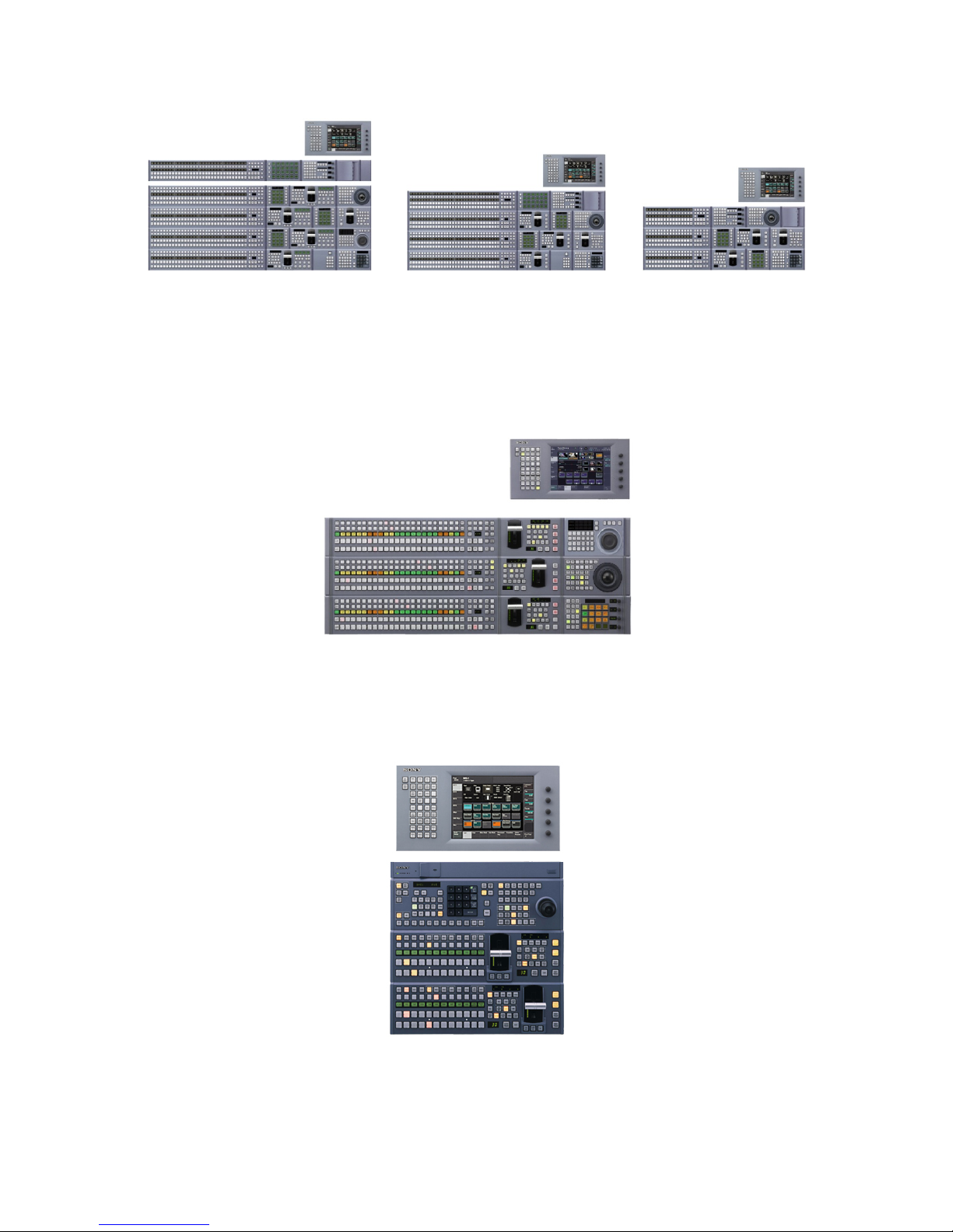
As an example, below, these are just a few of the different combinations of modules and sizes of CCP8000A control panels.
The CCP-6000 series control panel is smaller than the CCP-8000A panel. Instead of being configured
module by module, as the CCP-8000A series is, the CCP-6000 series comes as a standard unit. An
optional menu display and other modules may be added by the end user at purchase time. A System
Control Unit is also required. The CCP-6000 panel, below, is shown with an optional MKS-8036A Device
Control Module.
The CCP-9000 series control panels are ultra-compact, 19” wide panels. Unlike the CCP-8000A and CCP6000 series panels, the CCP-9000 series have the System Control Unit built-in. A menu display is
required and there may also be optional external modules.
pg. 6
Page 7

The MKS-8010B is a 1RU System Control Unit (SCU) for both the CCP-8000A and CCP-6000 control
panels. The SCU can be a maximum of 10 meters away from the control panel surface. The SCU is
connected to the control surface with either SWC-5005 cables (5m) or SWC-5010 (10m) 50-pin D-Sub
cables for power and data. These cable length choices were made at the time of ordering. Typically, the
SCU is mounted in the monitor wall or under the tabletop of the switcher control panel.. The power
buttons are recessed to prevent accidental operation by knees or feet when mounted under the
console.
Depending on the model of switcher, the DME (Digital Effects) system may be either internal option
boards or a separate chassis frame. With the 8000X system, DMEs are always in a separate frame. The
MVE-8000A is a 2RU frame that houses up to 4 channels of effects. The MVE-9000 is a 4RU frame that
also houses up to 4 channels. A total of 8 channels of DME can be installed in a single switcher system.
If more than 4 channels are purchased, an additional DME frame is required.
The MVS-7000X has two internal slots for plug-in DME boards. Each board has 2-channel capability. If
more than 4 channels of DME are required for a MVS-7000X system, then one external DME frame
(either MVE-8000A or MVE-9000) can also be installed.
The DME channels described here are in addition to the 2.5D Resizers that are standard on every keyer
on the 8000X and 7000X.
In keeping with the modular design of the MVS series, the Tally and Device Control Unit (DCU) is also a
separate frame from the switcher. There are two different models of DCU. The 3RU MKS-8700, which
allows for 5 option boards, provides the ultimate in flexibility for RS-422 ports and GPI/GPO and Parallel
Tally. The 1RU MKS-2700 has a fixed configuration of 6 RS-422 ports and 32 GPI/GPO/Parallel Tally. The
MKS-8700 has two serial tally ports whereas the MKS-2700 has none. If you require serial tally when
using a MKS-2700 please use the port marked EDITOR on the MKS-8010B System Control Unit (15-pin to
9-pin adapter is required).
Because the MVS system is so configurable, the descriptions above are not exhaustive. If you have any
questions regarding your unique system configuration, please contact your Sony Account Manager or
Sales Support Engineer.
pg. 7
Page 8

After your Installation…
Installation Check-Out
Standard to the MVS series is an on-site Installation Check-Out (ICO) by a Sony Field Service Engineer.
The amount of on-site time varies, depending on which switcher was purchased and the complexity of
the install (for example, was a router interface also purchased?). The typical on-site time is two days.
ICO scheduling is done through your Sony Account Manager, who will need the exact models of each
chassis and their respective serial numbers. Sony requires at least two weeks’ notice to schedule the
ICO. It is also important that the switcher be completely installed before the Service Engineer arrives.
The ICO does not cover mounting equipment, running/connecting cables or any System Design. If
these services are required, please contact your Sony account manager.
As a general rule the following items should be complete before the ICO date:
1. Complete installation of all switcher components, including cabling.
2. At least 4 video and 1 key source run to the inputs.
3. At least 2 monitors (PGM/PVW) are wired and operating
The ICO Field Service Engineer will ensure that:
1. The installation was done correctly and that all individual components are operating, as
designed, and communicating with each other.
2. All Inputs and Outputs are working
3. That all Mix/Effects boards and Keyers are operating
4. That all DME channels are operating
5. Assist in programing Tally and GPI
6. Assist in establishing communication between the MVS and external devices (i.e. DDRs, etc.)
Please note that while the ICO engineer can assist in making devices “talk” to the switcher, they are not
responsible for programming third-party devices. You may need to contact the manufacturer of the
third-party device for assistance.
The ICO also covers basic engineering menu system setup and basic troubleshooting and maintenance.
If a more thorough maintenance course is required, please contact your Sony Account Manager.
The ICO must occur before operator training. It is also strongly recommend that the ICO and operator
training are not back-to-back. If an error or defect is discovered during the ICO, it could impact your
ability to train operators.
pg. 8
Page 9

Operator Training
As an option, Sony can supply operator training for your MVS switcher. This training is listed as a lineitem option in the switcher quote and, typically, is a 3-day course; however, additional days can be
purchased.
Sony has a very experienced pool of certified contract trainers who use MVS switchers daily. There are
some important guidelines when determining your training schedule:
1. Sony requires at least 30 days’ notice to set up training. Many variables can affect our ability
to provide a trainer on your requested dates. In addition to your primary training dates, we
strongly recommend you have at least two alternate dates in case we are not able to
accommodate your first choice. Also note that our trainers’ personal schedules are booked
months in advance. Once booked, we will do our best to accommodate any changes to your
training schedule, but we cannot guarantee availability. Changing your training dates after
booking can affect your on-air date!
2. Training is limited to no more than a total of 10 hours per day. Adding additional time to a day
may result in additional charges for training.
3. Regardless of how much training has been purchased, if the customer requests a trainer to
make two or more separate visits, additional costs will apply.
4. Unless previously arranged, it is entirely at the trainer’s discretion to accept working a split shift
(for example, 5 hours in the 8a-1p time and another 5 hours in the 7p-12a time).
5. It is recommended that no more than 5 people attend each training class.
6. It is recommended that students with similar experience and skills be grouped together.
Printed operator manuals are not supplied; however a PDF version of the manual will be available and
may be distributed and printed freely.
Please contact your Sony Account Manager to arrange your operator training. Remember, a minimum
of 30 days advance notice is required.
pg. 9
Page 10

Section 2: Engineering Quick Start (Hardware)
This section covers the physical installation of your new switcher. Many items will be covered including
unpacking the boxes, identification of parts, wiring and basic setup.
Where to turn for help
Unpacking an installing a production switcher can be a daunting task, at best. While the installation
manuals for each component, and also this document, will provide you with all the information you will
need, sometimes a little extra help would be nice. Please contact your Sony Account Manager for
assistance. Your Sony Account Manager can assist you on missing items, if any, and has the ability to
bring in other resources, like Sales Support Engineers or Service Engineers, to make your installation go
as smoothly as possible.
What are all these boxes?
As described above, an MVS system consists of several, individual, components. Many of these will be
shipped separately. Different items come from different warehouses, so all your ordered items may not
arrive on the same day. For instance, most of the switcher components are shipped directly from the
factory in Japan, where other items like Ethernet switches, the menu arm and rack rails are shipped
from our domestic warehouses. Also, any items purchased as B-Stock (refurbished) will not be included
in configured product. For example, if your switcher is supposed to have the Frame Memory option, but
you had the opportunity to purchase that option as B-Stock, it will come packaged separately and will
not be installed in your switcher frame when it arrives.
It is important to note that this guide is not a replacement for the individual installation and operation
manuals that come with each component. Installation guidelines and procedures, as well as
specifications, can change without notice. Only the individual installation guides that are shipped with
your products are guaranteed to have the latest and most accurate information. This guide also does
not cover installing option boards or power supplies, including which slot they must be installed in.
Please refer to the individual installation guides that come with the product for detailed component
installation instructions.
Below describes the typical boxes you will receive, depending on which model switcher you purchased.
1. Switcher Chassis (10RU for 8000X, 8RU for 7000X)
2. MVE Digital Effects Chassis (2RU or 4RU, depending on model and number of channels)
• MVS-7000X has built-in DMEs that do not require their own chassis. If you have more
than 4 channels you will have an external MVE Chassis.
• MVS-8000X: If you have more than 4 channels you will receive two MVE chassis boxes
3. Device Control Unit Chassis (1 or 3RU, depending on model)
4. System Control Unit Chassis (1RU)
5. Control Panel (varies in size)
• CCP-8000A Series modular panels are pre-assembled and configured-to-order at the
factory. In the box you will find the main panel and the separate aux panel (if so
configured)
• CCP-6000 Series panels are pre-assembled at the factory but are not configured-to-
order as the CCP-8000A series panels are. If you ordered additional modules, such as a
pg. 10
Page 11

Shotbox™ or a Device Control Module, they will be shipped separately and must be
installed by the end user.
• CCP-9000 Series panels come as pre-fabricated units in their own boxes.
6. Menu Panel (if purchased)
7. SWC-50xx cables (interconnects between SCU and panel)
8. External module adapters for the control panel (MKS-8075A or MKS-8076)
9. Ethernet Switch Kit (if purchased)
• The MVS system requires three discreet, private, LANs to operate. Typically a kit
consisting of two rack-mount Ethernet switches and Ethernet cables, is purchased with
the system. The third LAN simply uses a crossover cable and doesn’t require a
dedicated switch.
10. MVS Menu Arm (if purchased)
11. Rack Rails
12. Power Cords
13. Aux Buss Remotes (if purchased)
14. Router Interface Items
• If you purchased a third-party router interface, you will receive four additional boxes
including a HKSP-R80 (controller), PFV-SP3100 or PFV-SP3300 (card cages for controller),
HK-PSU01 (backup PSU) and RMM-10 (rack rails).
Unpacking the boxes
Be careful to follow any directions and warnings on the exterior of the individual boxes to avoid damage
to your product. Also, please do not discard anything from the boxes until the ICO and training have
been completed.
Boxes that typically have extra items:
1. Control Panel
a. The roller-ball for the trackball module is not shipped installed as it can damage the
module. It will need to be installed by unscrewing the outside Z-Ring and dropping the
ball into the hole. Please tighten the Z-Ring when finished.
b. Button Puller. This item is required to remove the buttons from the control panel.
Attempting to remove the buttons without using this tool (i.e. using pliers) can result in
damage to the button which is NOT covered under warranty.
c. Additional Button labels. There are many sheets of additional button labels in a plastic
package. These will be needed during your ICO and operator training. DO NOT
DISCARD!
d. Terminating resistor for the reference loop connector.
e. Trackball overlay for device control.
i. This is only needed if a jog/shuttle module has not been installed in the control
panel. If this overlay is needed, it is simply set on top/around the buttons of the
trackball module.
2. Ethernet Switch Kit (if purchased)
a. TWO Ethernet Switches (one for Control LAN, one for DATA LAN – the PERIPHERAL LAN
use a crossover cable and does not require a dedicated switch)
b. 3x 100 feet length of Ethernet Cable
c. Crossover adapter and short cable for PERIPHERAL LAN
3. Switcher, DME, SCU and DCU Chassis
a. Terminating resistor for the reference loop connector
pg. 11
Page 12

Rack Mounting
Proper support is required when rack-mounting all components. Failure to provide proper support can
result in damage to the external chassis and internal boards which are not covered under warranty.
You do not need to put space between components when rack-mounting. All MVS components are
designed to be installed directly on top of each other.
Each rack-mountable item in an MVS system will have a rack mount kit specified at the time of ordering.
Typically, these are all RMM-10 kits. The single exception is the MVS-8000X chassis. The 8000X chassis
comes with its own mounting bracket. Please refer to the RMM-10 rack kits for assembly instructions
and the individual components’ installation manuals for mounting procedures.
Power Requirements & Environmental
Each chassis varies on its power requirements, depending on the model and the number of option
boards installed.
Please see each component’s installation manual for specifications on power consumption and
environmental considerations.
Where do the components go?
Typically, the switcher chassis, the DME chassis (if needed) and the DCU Chassis all are mounted
together in the Engineering/Terminal Gear racks. The connecting cables back to the control room are
three Ethernet cables. Even though the specification of the maximum distance for a single Ethernet run
is 384ft, Sony recommends your single cable-run is no longer than 305 feet. If you need runs longer
than that, you may have to convert Ethernet to fiber optic or explore other methods such as repeaters
or additional Ethernet switches.
As mentioned above, the SCU (MKS-8010B) does not get installed with the main switcher components.
The SCU is the power supply and CPU for the control panel. It must be within 10m of the control panel
surface (your cable lengths were determined at the time of purchase). The SCU is typically installed in
the monitor wall or in the console under the control surface. The power buttons are recessed to
prevent accidental shutdown by feet or knees.
Even though the DCU (MKS-2700 or MKS-8700) is typically racked with the switcher and DME chassis, it
is not required. If you have many external devices that use RS422 you may find it is more convenient to
shorten the RS422 cable runs by mounting the DCU closer to the third-party devices. The DCU uses a
single cross-over LAN cable that goes to the SCU (MKS-8010B). The same recommended 305ft Ethernet
limitation applies.
pg. 12
Page 13

Group and Unit ID settings
The MVS family uses fixed IP address, based upon the type of chassis. There are two settings that can be
changed by the end user. These are, primarily, to accommodate customers who have multiple switchers
on the same LAN or multiple individual chassis as part of the same system (for example 8 channels of
MVE-8000A DME will require two DME chassis, which will require different IP addresses.)
The two settings are Unit ID and Group ID. Both are set with DIP switches on the CPU card in each
chassis. Unit ID is the setting that tells the system there are multiple of the same chassis on the same
switcher system. For example, you have two DME chassis for 8 channels, each chassis holding 4
channels, one DME chassis would be set to Unit ID 1, the other to Unit ID 2. Another example is when
you have two control panels attached to the same switcher chassis. The first control panel would be set
to Unit ID 1, the second to Unit ID 2.
In the engineering Setup Menu, you will see a list of all switcher items that are discovered. You will see
items like SWR1, PNL1, DME1, DME2 (depending on your configuration). By the way, DME1 and DME2
are examples of two chassis being on a system, one being Unit ID 1 and the other being Unit ID 2.
If you have two completely separate control rooms, but they are both on the same switcher LAN, this is
where you set different Group IDs. Using a separate Group ID allows each control room to have
“proper” Unit ID’s without having to remember things like “DME4 is really DME2 in control Room 2”.
Typically a new switcher system delivered from the factory will have both the Group ID and Unit ID set
to 1 on all components. However, it is important to note that if you ordered more than one of the same
item (i.e. two DME chassis or multiple control panels), you must set the Unit ID’s before turning the
system on. We all know how computers love to have IP address conflicts. MVS is no different.
If you have purchased two complete switcher systems for two control rooms, you will need to plan out
which system will be Group 1 and which will be Group 2 and set the Group ID for the components
assigned to each room. Don’t forget the Unit ID settings also apply, as mentioned above.
Please refer to the installation manual on each chassis to determine how to set the Group and Unit IDs.
However, for a quick reference:
MVS-8000X is set on the CPU-82 board. Group ID is SW902 and Unit ID is SW903. Both can be accessed
from the front of the board. Typically they should both be set to 1.
MVS-7000X is set on the CPU-82A board. Group ID is SW902 and Unit ID is SW903. Both can be
accessed from the front of the board. Typically they should both be set to 1.
MVE-8000A is set on the
accessed from the front of the board. Typically they should both be set to 1 unless you have two units.
If you have two units that will be used for the same switcher, set SW103 on one chassis to 1 and the
other chassis to 2. In the next section, Wiring, make sure to physically wire the DME chassis set to Unit
ID1 as DME1 (channels 1-4) and the DME chassis set to Unit ID2 unit to DME2 (channels 5-8).
MKS-8010B (SCU) is set on the CA76 board. Group ID is SW9107 and Unit ID is SW9106. Both can be
accessed from the front of the board. Typically they should both be set to 1. However, if you have
multiple control panels that will be used with the same switcher chassis, the unit ID must be changed to
be unique for each MKS-8010B.
CA-54CFC board. Group ID is SW102 and Unit ID is SW103. Both can be
pg. 13
Page 14

MKS-2700 (Compact Device Control Unit) is set on the IF963 Board. Group ID is SW402 and Unit ID is
SW403. Both can be accessed from the front of the board. Typically they should both be set to 1.
MKS-8700 (Standard Device Control Unit) is set on the CA47 board. Group ID is SW754 and Unit ID is
SW755. Both can be accessed from the front of the board. Typically they should both be set to 1.
If you have any kind of a non-standard configuration or would just like a little help, please feel free to
contact your Sony Account Manager. They can connect you with the right people to help.
Wiring
LANs
The MVS System uses three private LANs for communication. The CONTROL LAN handles real-time
communication between the control panel and the individual chassis. The DATA LAN handles packetized
communication, such as file loading/saving, Frame Memory transfers, etc. between the individual
chassis and the control panel. Finally the PERIPHERAL LAN handles communication from the control
panel to the DCU for Tally, GPI/GPO and RS422. These networks are discreet, by design, and keep only
related network traffic isolated to the proper LAN. Please do not attach any cables that would connect
one LAN to another. However, in an emergency (such as a switch failing) you can combine LANs
together to stay “on the air”, but it is not recommended to operate for long periods of time this way.
Unless specifically directed by Sony personnel or a Sony equipment manual, do not connect your
“house” or any other network into the Ethernet switches for your MVS switcher.
After rack mounting the two Ethernet switches, please mark one of them as CONTROL LAN and the
other as DATA LAN. This will help ensure all future connections go to the correct switch.
First, let’s connect the CONTROL LAN cables. You will find CTRL RJ-45 connectors on the Switcher
chassis (toward the bottom), the SCU and the DME chassis (if you have one). If you have 2 DME chassis,
then it will be necessary to connect both DME chassis’ CTRL LANs to the CONTROL LAN Ethernet switch.
Next, repeat the above procedure, except this time, connect all the DATA RJ-45 connectors on each
device into the DATA LAN Ethernet switch.
To connect the DCU to the SCU, a dedicated Ethernet switch is not required since only the two devices
“talk” to each other. Simply use a crossover cable or crossover adapter to connect the SCU and DCU
“PERIPH” RJ-45 connectors together. If you purchased the Ethernet Switch kit from Sony, you will find a
long Ethernet cable, a crossover adapter and a short jumper cable for this purpose.
If you have the Frame Memory option in your MVS switcher, please attach a cat5e cable (not provided)
between the DATA LAN Ethernet switch and the FM LAN port on the back of the switcher chassis. This
speeds up communication between the Frame Memory system and the control panel.
pg. 14
Page 15
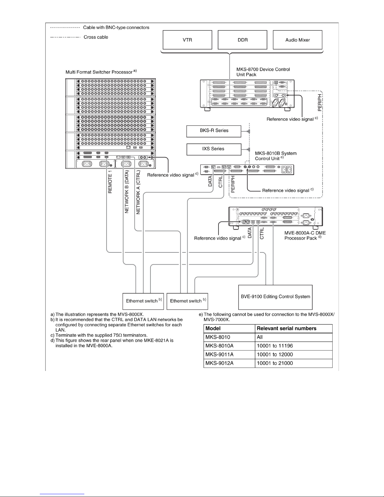
In the above diagram, you can see that the Switcher, DME (if needed) and Panel (really the SCU) all have
CNTL and DATA Ethernet cables going to their respective switches. You can also see that the DCU has a
crossover cable going to the SCU.
pg. 15
Page 16
SWITCHER CHASSIS (MVS-7000X only)
pg. 16
Page 17

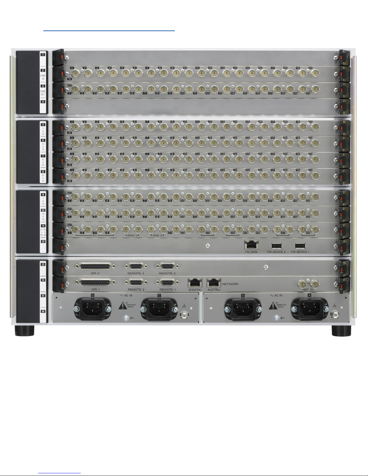
Video Inputs
The MVS-7000X has up to 80 non-looping inputs, each in blocks of 20. These can be seen in the above
photo on slots 5-8. All inputs are “mappable” from the control panel menu to any crosspoint button so
there is no need to match the physical input to where the operator would like to select it. Also, there is
no differentiation between video and key inputs. Wire key inputs to any of the input connectors.
Video/Key matching is done later in the setup menu.
Video Outputs
An MVS-7000X can have either 24 or 48 outputs. If only 24 outputs are configured, then there will be a
blank in slot #10. Please notice that Slot #9 has outputs 1-20 and in the middle of slot #11 you will find
outputs 21-24. If you have 48 outputs, then you will find Outputs 25-44 on Slot #10 and Outputs 45-48
on the right-side of slot #11. Outputs 23-24 and 47-48 have dual outputs. If there is a blank in slot 10
(switcher only has 24 outputs), then the BNC connectors for Outputs 45-48 are not functional.
Just like inputs, all outputs on the 7000X are mappable from the Setup Menu. However, the default
factory setting is:
Out 1 M/E 1 OUT 1 (M/E 1PGM)
Out 2 M/E 1 OUT 2 (M/E 1 PVW)
Out 3 M/E 2 OUT 1 (M/E 2 PGM)
Out 4 M/E 2 OUT 2 (M/E 2 PVW)
Out 5 M/E 3 OUT 1 (M/E 3 PGM)
Out 6 M/E 3 OUT 2 (M/E 3 PVW)
Out 7 P/P OUT 1 (P/P PGM)
Out 8 P/P OUT 2 (P/P PVW)
Out 9 EDIT PVW
When you are wiring outputs, please note that the EDIT PVW output is the correct output for “Preview.”
This enables the preview switcher (which is normally set to P/P PVW) to also show other M/E previews
and other important signals like “Show Key.”
Reference
The MVS-7000X requires house “black” reference to operate. If you are not looping black, please
connect a 75-ohm terminating resistor to the loop connector. Both “black” and tri-level sync are
permitted, however tri-level sync is only required for special applications, like 24P production. It is also
very important to note that BLACK reference is required when using the internal format converters. The
internal format converters will not work with tri-level sync.
pg. 17
Page 18

Format Converter
If you purchased the optional format converter card, you have 8 format converter input channels and
either 2 or 4 format converted outputs (depending on how many output cards are in the frame).
Any of the 80 primary inputs can be internally routed to a format converter input channel. This is done
in the setup menu. On slot #11, you will see four connectors marked as FC 1-4. These are the Format
Converter outputs. If your switcher has only 24 outputs, then FC3-4 are not functional.
Multi-Viewer
The MVS-7000X has up to two Multi-Viewer Outputs as a standard feature. If your switcher is
configured with 24 outputs, then the MSD1 connector on Slot 11 will be active. If you have 48 outputs,
then both MSD1 and MSD2 will be active.
The Multi-viewer is a basic system that allows multiple outputs to be shown simultaneously on a single
monitor. There are two options for the type of display: 4 (quad split) and 10 (two large and 8 small).
On-Air tally is provided. Multi-Viewer settings are made in the Engineering Setup menu.
The Multi-Viewer is not designed to replace the large monitor-wall systems that are typically found in
today’s production environments. However, it is a handy standard feature of the MVS-X series to,
perhaps, removes items the whole control room doesn’t need to see, like M/E outputs and put them on
a separate monitor just for the switcher operator. For planning your output assignments, it is important
to remember two things:
• For a signal to appear on the Multi-Viewer, it must be assigned to a physical output
• Each Multi-viewer’s window assignments are exclusive to its physical output card. This means
that Multi-Viewer #1 can only “see” signals that are assigned to Out 1-24. Multi-Viewer #2 can
only “see” signals that are assigned to Out 25-48. For example, it is not possible assign a signal
that is mapped to output 51 to Multi-Viewer #1, as Multi-Viewer #1 can only access outputs 1-
24.
DME Inputs and Outputs
The 7000X has the ability to use up to 4 channels of plug-In, internal, DME channels. However the MVS
system, as a whole, can accommodate 8 channels. If you ordered your 7000X with more than 4 channels
of DME, you will have an external DME chassis that needs to be hooked up to the switcher. If you have
more than 4 channels, you will have also purchased dedicated DME input and Output backplane boards.
If, for some reason, you are not using the internal DMEs on the 7000X, up to 8 channels (2 external
chassis) of MVE-8000A or MVE-9000 DME can also be connected to the 7000X switcher via these
dedicated connectors.
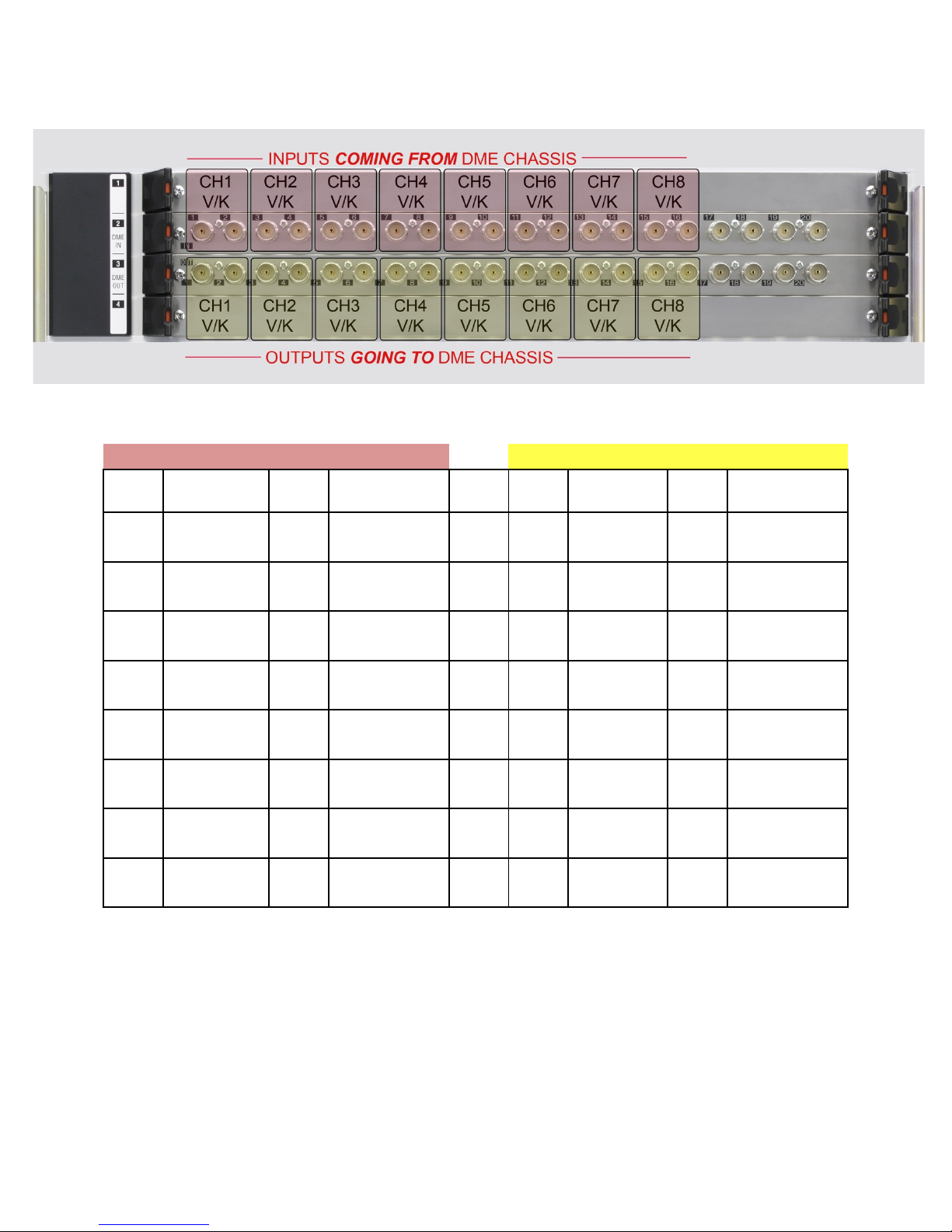
MVS-7000X backplane Slots 2 & 3 are Input and Output connectors when using an external DME chassis
(typically for more than 4 channels). Slot # 2 is for video coming FROM the DME (connected to the
OUTPUT connectors on the DME Chassis). Slot #3 is for video GOING TO the DME (connected to the
INPUT connectors on the DME Chassis). Using these dedicated connectors saves primary inputs and
outputs, while still allowing the external DME chassis to function as a fully integrated device. In very
specific production requirements, it may be desirable to wire the DME chassis as a true external device,
meaning using primary inputs and outputs. Since this type of wiring is rare, please contact your Sony
account manager or Sales Support Engineer if you need assistance.
pg. 18
Page 19
SLOT 2 (FROM DME)
SLOT 3 (TO DME)
SIGNAL
(DME1)
SIGNAL
(DME1)
The following shows the backplane of the MVS-7000X’s DME I/O:
BNC
BNC SIGNAL(DME2) BNC
BNC SIGNAL(DME2)
1 CH1 V Out 9 CH5 V Out 1 CH1 V In 9 CH5 V In
2 CH1 K Out 10 CH5 K Out 2 CH1 K In 10 CH5 K In
3 CH2 V Out 11 CH6 V Out 3 CH2 V In 11 CH6 V In
4 CH2 K Out 12 CH6 K Out 4 CH2 K In 12 CH6 K In
5 CH3 V Out 13 CH7 V Out 5 CH3 V In 13 CH7 V In
6 CH3 K Out 14 CH7 K Out 6 CH3 K In 14 CH7 K In
7 CH4 V Out 15 CH8 V Out 7 CH4 V In 15 CH8 V In
8 CH4 K Out 16 CH8 K Out 8 CH4 K In 16 CH8 K In
Notes:
1. If an internal DME is installed it will always be DME1 (Unit ID 1) and BNC connectors 1-8 for both
input and output are not used.
2. If a chassis of MVE-8000A or MVE-9000 is installed in addition to the internal DME, connect the
external chassis to BNC connectors 9-16 (CH5-8).
3. If no internal DME is installed then BNC Connectors 1-8 (CH1-4) are for the first external chassis and
9-16 (CH5-8) are for the second external chassis.
pg. 19
Page 20
SWITCHER CHASSIS (MVS-8000X only)
pg. 20
Page 21

Video Inputs
The MVS-8000X has up to 164 non-looping inputs, each in blocks of 20 with a couple of exceptions. Each
of the backplane input cards has 20 BNC connectors. The 8000X comes standard with 24 inputs. The
first 20 of those inputs are found on slot #5. The extra 4 inputs are actually inputs 141-144 and can be
found on slot #12. Regardless of how many extra inputs are purchased, inputs 141-144 are always
available. For example, if you purchased an 8000X with 64 inputs, you would find inputs 1-20 on slot #5,
inputs 21-40 on slot 6, inputs 41-60 on slot #7 and inputs 141-144 (the extra 4) on slot #12.
So far we’ve accounted for 144 of the possible 164 inputs. The MVS-8000X may also have an additional
20 inputs in slot #3 called “Premium Inputs.” Premium Inputs are special inputs that are available on the
switcher when the second matrix board is installed. The second Matrix board is automatically installed
when either the inputs exceed 64 or when the 8000X is configured as a 5 M/E system. Premium Inputs
can be used as regular, primary inputs. However, for your wiring design, it is very important to note that
if you have M/E 4 (you have a 5 M/E switcher) that the keyers on M/E 4 can only get their key signals
from these Premium Inputs. Standard inputs cannot be used as key signals for the keyers on M/E 4.
However, Premium Inputs can appear everywhere on the switcher. A good rule of thumb is…. If you
have M/E 4 (i.e. a 5 M/E 8000X) then put all your key signals on the premium input card in slot #3.
In addition, if you purchased any internal format converters, the inputs for the format converter
channels will also be on slot #12. They are in blocks of eight, as each format converter card is an 8channel option.
Video Outputs
A MVS-8000X can have either 24 or 48 primary outputs. If only 24 outputs are configured, then there
will be a blank in slot #14. Please notice that Slot #13 has outputs 1-20 and in the middle of slot #15 you
will find outputs 21-24. If you have 48 outputs, then you will find Outputs 25-44 on Slot #14 and
Outputs 45-48 on the right-side of slot #15. Note that output 23-24 and 47-48 have dual outputs. If
there is a blank in slot #14 (switcher only has 24 outputs), then the BNC connectors for Outputs 45-48
are not functional.
Just like inputs, all outputs on the 8000X are mappable from the Setup Menu. However, the default
factory setting is:
Out 1 M/E 1 OUT 1 (M/E 1PGM)
Out 2 M/E 1 OUT 2 (M/E 1 PVW)
Out 3 M/E 2 OUT 1 (M/E 2 PGM)
Out 4 M/E 2 OUT 2 (M/E 2 PVW)
Out 5 M/E 3 OUT 1 (M/E 3 PGM)
Out 6 M/E 3 OUT 2 (M/E 3 PVW)
Out 7 P/P OUT 1 (P/P PGM)
Out 8 P/P OUT 2 (P/P PVW)
Out 9 EDIT PVW
When you are wiring outputs, please note that the EDIT PVW output is the correct output for “Preview.”
This enables the preview switcher (which is normally set to P/P PVW) to also show other M/E previews
and other important signals like “Show Key.”
pg. 21
Page 22

MVS-8000X Dedicated M/E Outputs
In addition to the primary outputs, the MVS-8000X also has, on slot 4, dedicated outputs for each M/E.
There are four for each M/E and Program/Preset. These output signals correspond to the first 4
“internal” outputs of each M/E, and are set in the Engineering Setup Menu. By default they are:
1. PGM
2. PVW
3. CLEAN
4. KEY PVW 1
However, please keep in mind that the majority of switcher operators run the M/Es in a mode called
“Multi-Program 2” which changes the output settings of the M/E bank (for instance, each M/E’s “sub”
output is fixed at M/E Output 6 – which does not have a physical, dedicated output connector and must
be routed through a standard output. It is recommended you consult with your operators before
deciding to use these M/E outputs.
Reference
The MVS-8000X requires house “black” reference to operate. If you are not looping black, please
connect a 75-ohm terminating resistor to the loop connector. Both “black” and tri-level sync are
permitted, however tri-level sync is only required for special applications, like 24P production. It is also
very important to note that BLACK reference is required when using the internal format converters. The
internal format converters will not work with tri-level sync.
Format Converters
If you purchased either one or two of the optional format converter cards, you can have either 8 or 16
format converted inputs (depending on whether you purchased one or two boards) and either 2 or 4
format converted outputs (depending on how many output boards are in the switcher chassis).
On slot #15, you will see four connectors marked as FC 1-4. These are the format converter outputs. If
your switcher has only 24 outputs, then FC3-4 are not functional.
Format converters on the 8000X have dedicated inputs on slot #12. If you have a single source that
sometimes outputs SD and sometimes outputs your “normal” house production format (i.e. 1080i) then
you will need to send the signal to both a format converter input and a standard primary input.
pg. 22
Page 23

Multi-Viewer
The MVS-8000X has up to two Multi-Viewer Outputs as a standard feature. If your switcher is
configured with 24 outputs, then the MSD1 connector on Slot 15 will be active. If you have 48 outputs,
then both MSD1 and MSD2 will be active.
The Multi-viewer is a basic system that allows multiple outputs to be shown simultaneously on a single
monitor. There are two options for the type of display: 4 (quad split) and 10 (two large and 8 small).
On-Air tally is provided. Multi-Viewer settings are made in the Engineering Setup menu.
The Multi-Viewer is not designed to replace the large monitor-wall systems that are typically found in
today’s production environments. However, it is a handy standard feature of the MVS-X series to,
perhaps, removes items the whole control room doesn’t need to see, like M/E outputs and put them on
a separate monitor just for the switcher operator. For planning your output assignments, it is important
to remember two things:
• For a signal to appear on the Multi-Viewer, it must be assigned to a physical output
• Each Multi-viewer’s window assignments are exclusive to its physical output card. This means
that Multi-Viewer #1 can only “see” signals that are assigned to Out 1-24. Multi-Viewer #2 can
only “see” signals that are assigned to Out 25-48. For example, it is not possible assign a signal
that is mapped to output 51 to Multi-Viewer #1, as Multi-Viewer #1 can only access outputs 1-
24.
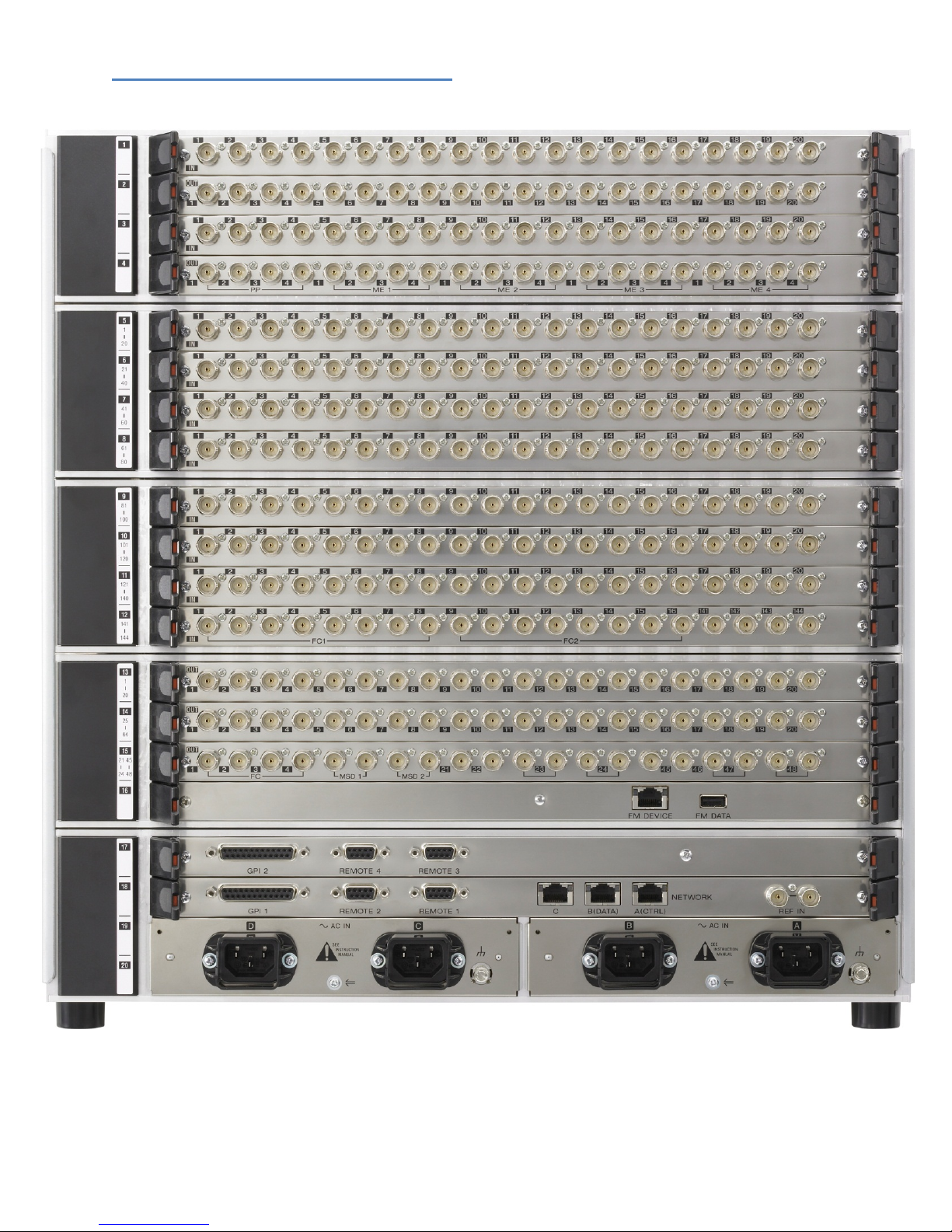
DME Inputs and Outputs
The 8000X has the ability to use up to 8 channels of DME. Each group of 4 channels will be housed in an
external chassis – a MVE-8000A, a MVE-9000 or a combination of both. If you ordered your 8000X with
any DME channels, then you will have also purchased dedicated DME input and Output backplane
boards.
Slots 1 & 2 are Input and Output connectors when using an external DME chassis. Slot # 1 is for video
coming FROM the DME (connected to the OUTPUT connectors on the DME Chassis). Slot #2 is for video
GOING TO the DME (connected to the INPUT connectors on the DME Chassis). Using these dedicated
connectors saves primary inputs and outputs, while still allowing the external DME chassis to function as
a fully integrated device. In very specific production requirements, it may be desirable to wire the DME
chassis as a true external device, meaning using primary inputs and outputs. Since this type of wiring is
rare, please contact your Sony account manager or Sales Support Engineer if you need assistance.
pg. 23
Page 24
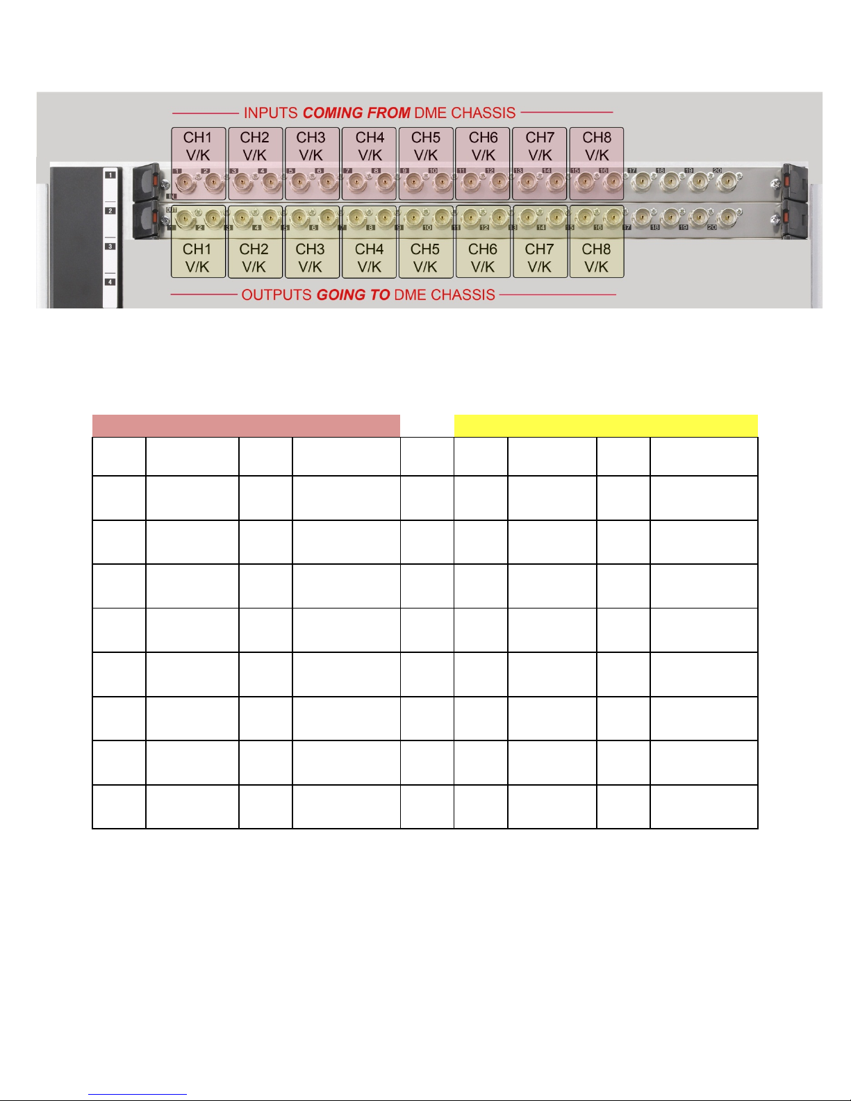
The following shows the backplane of the MVS-8000X’s DME I/O:
SLOT 1 (FROM DME)
SLOT 2 (TO DME)
SIGNAL
(DME1)
SIGNAL
(DME1)
BNC
BNC SIGNAL(DME2) BNC
BNC SIGNAL(DME2)
1 CH1 V Out 9 CH5 V Out 1 CH1 V In 9 CH5 V In
2 CH1 K Out 10 CH5 K Out 2 CH1 K In 10 CH5 K In
3 CH2 V Out 11 CH6 V Out 3 CH2 V In 11 CH6 V In
4 CH2 K Out 12 CH6 K Out 4 CH2 K In 12 CH6 K In
5 CH3 V Out 13 CH7 V Out 5 CH3 V In 13 CH7 V In
6 CH3 K Out 14 CH7 K Out 6 CH3 K In 14 CH7 K In
7 CH4 V Out 15 CH8 V Out 7 CH4 V In 15 CH8 V In
8 CH4 K Out 16 CH8 K Out 8 CH4 K In 16 CH8 K In
Notes:
Connectors 1-8 (CH1-4) are for the first external chassis and 9-16 (CH5-8) are for the second external
chassis.
pg. 24
Page 25
Control Panel
Panel Type
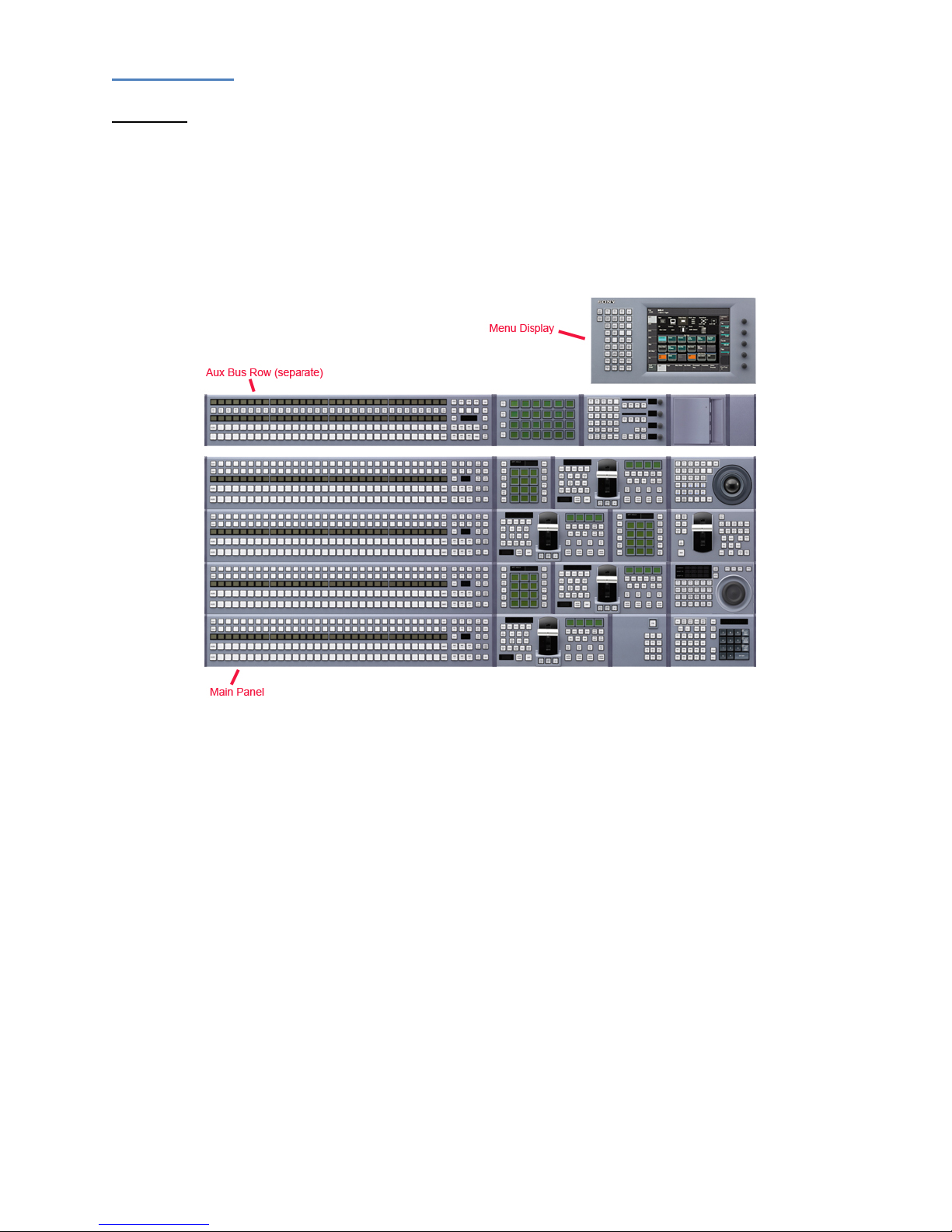
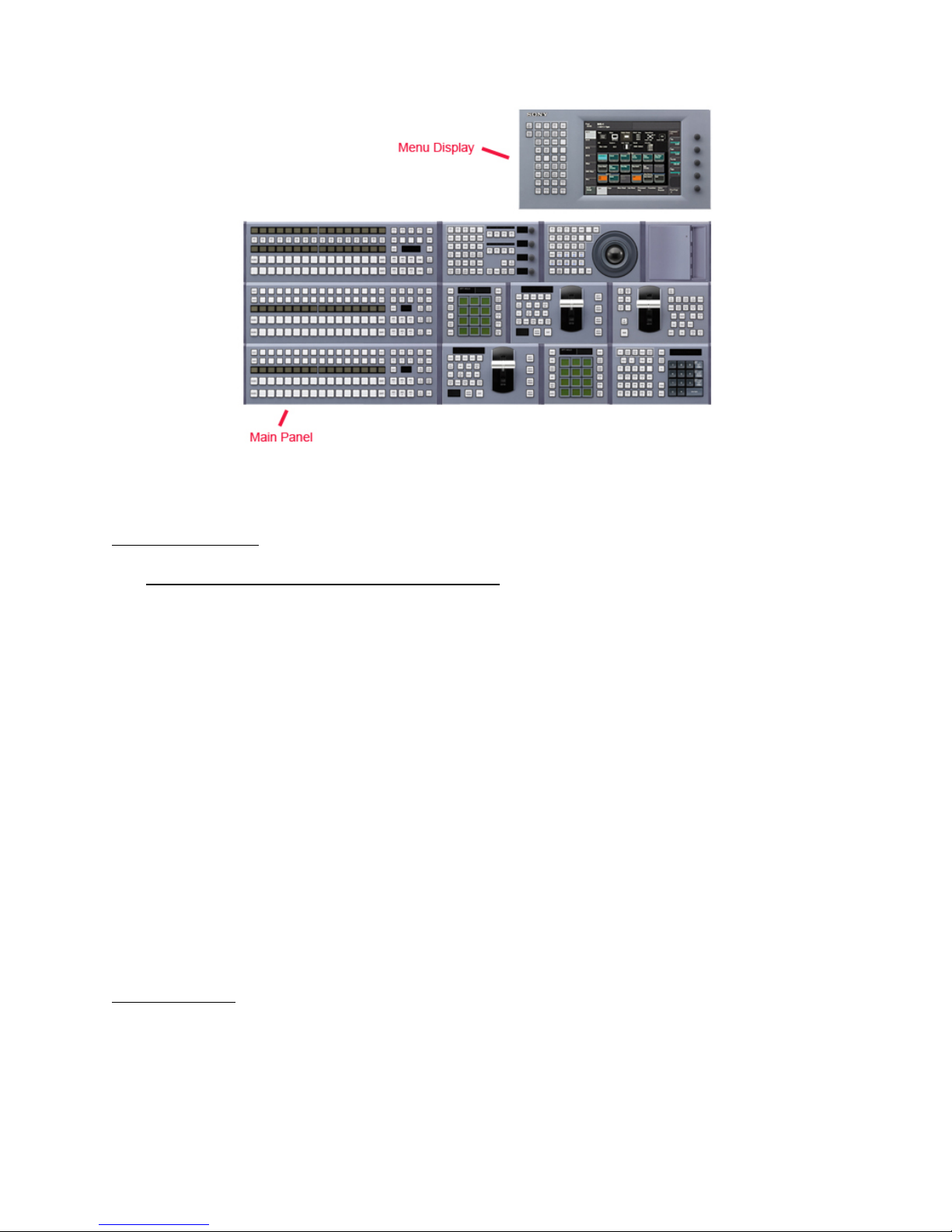
As mentioned earlier in this guide, the control panel is made up of several parts: The main panel,
possibly an aux panel, the menu display, the menu arm and the System Control Unit (SCU).
You first need to determine how many sections your main panel has. If your panel is a 4 M/E panel,
then it must have a separate Aux row. This will be a 5-inch tall section that is usually as wide as the
switcher panel itself. Usually, this separate Aux row will mount perpendicular or at a more vertical angle
to the main panel.
4 M/E Panel with Separate Aux
pg. 25
Page 26
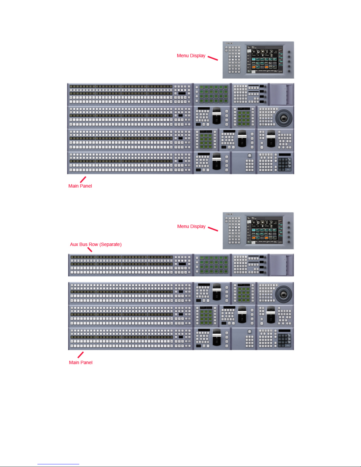
If your panel is a 3 M/E panel, then the Aux portion can either be “integrated” at the top of the main
panel or it can be separated.
3 M/E Panel with Integrated Aux
These panel decisions were made at the time of purchase. Whether your aux is integrated or separate is
one of the few items that are not easy to change after manufacture.
3 M/E Panel with Separate Aux
pg. 26
Page 27
If you have a 2, or even a 1, M/E panel, then the Aux portion is always “integrated” into the panel.
2 M/E Panel with Integrated Aux
Connecting the Panel
First make sure the SCU (MKS-8010B) is powered down. Connecting control panel cables or even
adding and removing individual panel modules while power is applied can result in blown fuses which
are time consuming to replace.
Next, locate the SWC cables (thick, black cables with 50 pin D-Sub connectors). One cable is going to
connect the main panel (the big part) to the SCU. On the main panel, the connector will be in the back
on the right side (if you are looking from the back). On the SCU, connect this cable to “MAIN PANEL”.
If you have a separate Aux row, please connect another SWC cable to the back of the aux row and the
other end to the SCU on the port marked “EXT PANEL1”. If your Aux is integrated into the main panel
(no separate aux row) then there is nothing to connect. The switcher processor will determine which
row is the aux automatically.
If you are using an MVS-8000X switcher and have a 5 M/E panel, you will have another separate row for
M/E 4. This will connect with an SWC cable in the same manner as the Aux row, except connect M/E 4
to the EXT PANEL2.
Connect another SWC cable to the menu display (it’s in the back). The other end goes to the SCU port
marked “MENU”.
External Adapters
Depending on your configuration, you may also have external modules. Sometimes this is because the
standard layout of the control panel isn’t large enough to accommodate all the requested modules,
other times it’s because the operator wanted a module mounted outside the panel. Since the modules
are all designed to fit within the main panel, using a module outside of the panel requires an adapter.
For all modules, except the USB/Memory Stick Module, this adapter is the MKS-8075A. Please refer to
pg. 27
Page 28

the control panel installation manual for a complete description of the MKS-8075A adapter and its
mounting options (they can be daisy-chained, connected together, stacked horizontally or vertically,
etc). You will notice in the MKS-8075A box there is a small 6-inch SWC cable. This cable is for daisychaining the external adapters together (when two or more are purchased) and is not for connecting to
the SCU. Please be sure to save that cable as they are quite expensive to replace if you find you need
one later.
Whether you are daisy-chaining them or not, the first MKS-8075A adapter needs to be connected to the
SCU. If you purchased the 8075A, you would have automatically purchased an additional SWC cable.
This cable may be 5 or 10 meters. Connect one end to the SCU port marked “EXT PANEL2” (if you have
an integrated Aux and did not hook anything up to the EXT PANEL1 connector you may use that instead),
then connect the other end to the 8075A adapter. Please note that each side has a connector, each
with a unique gender. The opposite gender is used to daisy-chain to another 8075A.
Follow the installation manual instructions for placing the module you want mounted externally into the
8075A. MAKE SURE THE SCU POWER IS OFF WHILE MOUNTING THE MODULE.
Be sure to tighten all the SWC cables before applying power to the SCU, as having a cable detach while
power is applied can also result in a blown fuse.
USB/Memory Stick
We need to connect the supplied USB cable to the SCU. Please connect the Type A (flat) end of the
supplied USB cable to the DEVICE port on the SCU. If you have a USB/Memory Stick Module, the Type-B
end (square) needs to be plugged into the back of the panel where the USB Module is located. For
instance, if the USB module is in the separate aux row on a 4 M/E or 3 M/E panel, you would connect
the Type-B plug near where you already connected the SWC cable for the aux row. If the USB module is
in the main (large) section of the panel, then connect the Type-B plug near the SWC cable for the main
panel. It is also possible that your USB module is outside the panel in a MKS-8076 adapter. The MKS8076 adapter looks almost identical to the MKS-8075A adapter, described above, except the MKS-8076
adapter is used exclusively for the USB module and has only a USB Type-B connector instead of the 50pin connector of the MKS-8075A.
If you do not have a USB module, then it is likely you will use a USB hub of your own. Please connect the
Type-B plug to your self-powered USB hub.
Other Control Panel connections
The SCU also requires house “black” reference. If you are not looping reference, please terminate with a
75-ohm terminating resistor.
The network cables should all be connected as described above in the LAN section. If they have not yet
been connected to all chassis, please refer above to the LAN section and wire the LANs before
continuing.
The Timecode BNC connector is only used when the Plug-in Editor option is purchased with the
switcher. If you have purchased this option, connect house timecode (unbalanced BNC audio) to this
connector.
pg. 28
Page 29

MENU DISPLAY (15-pin) is a mirror of the touchscreen menu display. This is useful during training to
display the menu on a larger screen or projector for all to see. It can also be used in an emergency if a
fault develops in the touchscreen. MENU DISPLAY is a standard analog VGA connector.
EXT DISPLAY (15-pin) is used, exclusively, when the Plug-In Editor option is installed. This will be the EDL
display. EXT DISPLAY is a standard analog VGA connector.
REMOTE is to connect Aux Bus remote panels (1 or 3 RU – MKS-8080 or MKS-8082, respectively) to the
switcher. If you have one or more of these panels, please refer to the installation instructions that came
with them.
DME Chassis
If you have an MVE-8000A or MVE-9000A DME chassis in your switcher they need to be wired for video
into and out of the main switcher chassis. Please see the section above (under switcher wiring) on how
to wire-in the DME channels. Note that there are wiring instructions specific to the model switcher you
purchased.
Each DME chassis also require house “black” reference. If you are not looping reference, please
terminate with a 75-ohm terminating resistor.
Any external DME chassis must also be rack-mounted with proper support as they are heavy. In almost
all cases, there will be a backup power supply to plug-in along with the primary.
If you have a 7000X switcher then there is a good chance you will not have any external DME chassis as
the 7000X supports up to 4 channels of plug-in DME. However, the 7000X can also accommodate an
additional 4 channels of external DME to augment the internal 4. In very rare cases, a 7000X can have 8
channels (2 chassis) of external DME without using any internal DMEs.
If you have an 8000X switcher, then all DME channels will be external.
Device Control Unit (DCU)
You will likely have either a MKS-2700 or MKS-8700 Device Control Unit (DCU) that must be rackmounted as well. The MKS-2700 is a small, 1RU frame that has 32 parallel Tally/GPI outputs and 6 RS422 connectors. The MKS-8700 is a larger, 3RU frame that has 5 slots for option cards. Currently there
are two option cards offered: the MKS-8701 is a 54 Tally/GPI Output card and the MKS-8702 is a 6 RS422 card. If you ordered a MKS-8700 DCU, it is likely all the option cards have already been installed. If
they came separately, please see the install manual for the MKS-8700 for instructions for installing
boards.
The DCU chassis also require house “black” reference. If you are not looping reference, please
terminate with a 75-ohm terminating resistor.
The DCU must also be rack-mounted with proper support. In almost all cases, there will be a backup
power supply to plug-in along with the primary.
pg. 29
Page 30
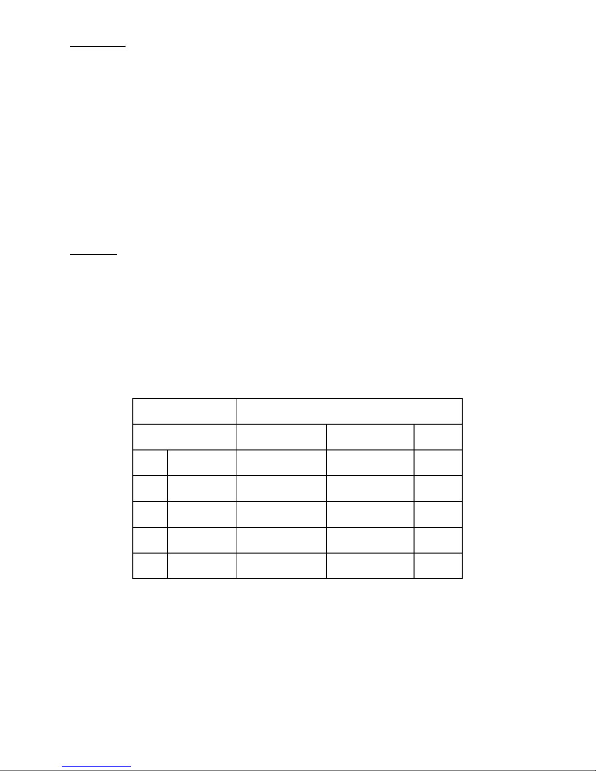
Parallel Tally
MIRANDA
SONY
RJ45
SCU Editor Port
DCU 8000 Port
PIN
SIGNAL
15 PIN
9 PIN
SIGNAL 1 RX+ 3 3
TX+
2
RX-
11
8
TX-
3
TX+
10
7
RX+ 6 TX- 2 2
RX-
Both the MKS-2700 and MKS-8700 have parallel tally outputs that you will likely want to wire to external
devices, like CCUs. Just like the video inputs and outputs on the MVS switcher, all parallel tallies are
completely “mappable” from the setup menu. However, as a factory default they will all be set 1-1,
meaning tally port/pin 1 will correspond to input 1, tally port/pin 2 will correspond to input 2 and so on.
Also, by default, Output 7 (factory default for P/P PGM1) will have been programmed as the Main (R1,
or Red-1) tally output. Tally programming is input-based and has nothing to do with what control panel
button that input has been assigned to. There are 8 independent tally systems in MVS, therefore tally
programming can be incredibly easy (from the factory default) to very complex. Please see the install
guides for the MKS-2700 and MKS-8700 (depending on which model you purchased) for pin-out wiring
specifications for the tally ports.
Your Install Check-Out Field Service Engineer can assist you in programming tallies during the ICO.
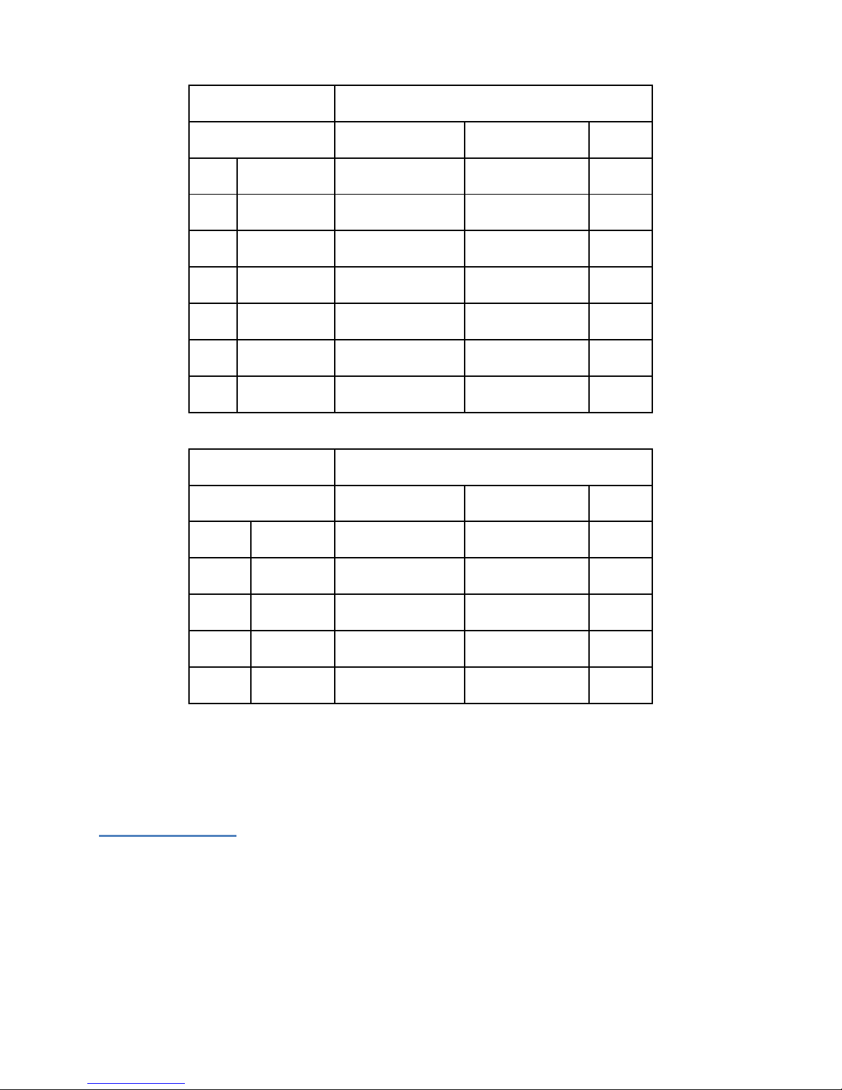
Serial Tally
The MKS-8700 DCU has 2 serial tally connectors on its frame (typically used for monitor walls and
routers). Both can be set in the switcher’s setup menu independently. The MKS-2700 does not have a
serial tally connector. However if serial tally is required when using a MKS-2700, the EDITOR 15-pin port
on the System Control Unit (MKS-8010B) can be repurposed as a Serial Tally Port. Since most serial tally
connections are 9-pin, you will need to manufacture a 15-pin to 9-pin adapter. The pin-out
specifications for the most popular third-party manufacturers that use serial tally are below. If your
manufacturer is not listed, please contact your Sony Account Manager. They can help you find the
resources to assist in making your device work properly with your MVS switcher.
pg. 30
Page 31
EVERTZ PTX-MVS
SONY
PHOENIX TERMINAL
SCU Editor Port
DCU 8000 Port
PIN
SIGNAL
15 PIN
9 PIN
SIGNAL 1 TX- 2 2
RX- 2 RX-
11
8
TX- 3 TX+
10
7
RX+ 4 TX- 3 3
RX- 5 GND 4 4
GND 6 GND
12
6
GND IMAGE VIDEO
SONY
TSI COM PORT
SCU Editor Port
DCU 8000 Port
9 PIN
SIGNAL
15 PIN
9 PIN
SIGNAL 2 TX- 2 2
RX-
3
RX+ 3 3
TX+
7
TX+
10
7
RX+ 8 RX+
11
8
TX+
Either DCU connects to the MVS system the same way – via the PERIPHERAL LAN. Please refer, above,
to LAN WIRING.
Aux Bus Remotes
Sony manufactures two different Aux Bus remote panels for the MVS system: the 1RU MKS-8080 and
the 3RU MKS-8082.
The 1RU MKS-8080 is typically used for a single aux bus remote. It has 32 small buttons and a jog dial to
set which bus is being controlled (and other programming).
The 3RU MKS-8082 is more of an X-Y panel that can control many aux destinations at once. It has larger
buttons with 4-character LED labeling.
pg. 31
Page 32

Each aux remote (up to 16 without an additional controller) is daisy-chained from one to the other with
75-ohm coax video cable. At each end a “T” connector and a 75-ohm terminating resistor must be used.
It is also important to set each aux bus remote’s panel ID number before attaching to the chain.
Please refer to the specific aux panel’s installation guide on how to install aux bus remotes (including
how to set the ID# and wiring) with the switcher system.
If you are using aux bus remotes, it is also necessary to set the SCU’s ID on the CA76 board. The ID can
be set with S1908 (Station ID). It is typically set to ID 2 at the factory, but when using aux bus remotes it
is necessary to set this to ID 1. However, if you are planning to have a routing switcher connected,
please leave this at ID 2.
After the Install
Routine Maintenance
Although there are very few moving parts in an MVS system, it is important to perform preventative
maintenance at regular intervals.
Items that should be regularly maintained:
1. Filter cleaning
a. The filters in the front of each chassis should be cleaned of dust and other contaminants
every two months. Please refer to the individual unit’s installation manual (Periodic
Inspection and Maintenance) for additional information.
2. Chassis Fan Maintenance
a. The fans in each chassis should be cleared of dust every month. Please refer to the
individual unit’s installation manual (Periodic Inspection and Maintenance) for
additional information.
3. Power Supplies
a. The power supplies should be replaced every 7.5 Years. Please refer to the individual
unit’s installation manual (Periodic Inspection and Maintenance) for additional
information.
Other tips to keep your new switcher working well…..
1. Wipe the control panel, switches, and faders with a dried cleaning cloth. Use a cleaning cloth
moistened with water or lukewarm water for any persistent stains. Be sure to use a wrung cloth
for wiping the control panel since water droplets can causes malfunctions. Do not use any
chemical, solvent, or cleaner, or wipe with excessive force hard to avoid damaging the panel.
2. Do not use hand sanitizer on the control panel. Hand sanitizers have alcohol which can cause
problems with the plastic on the buttons.
3. Be sure to back up your internal hard drive to USB drives on a regular basis.
pg. 32
Page 33

Start-up
If you have not yet done so, please plug-in and turn on all power supplies on all chassis. Please note that
the MVS-8000X switcher chassis requires at least three power supplies to be turned on to operate. The
MVS-7000X chassis requires at least two power supplies to be turned on to operate.
It will take approximately 30-45 seconds for the control panel to completely light up and about another
2 minutes for the menu display to finish initializing.
If everything has powered up correctly, you should see the LCD labels on the control panel lit up (if this
came brand new from the factory they are all likely orange colored). You should also see the menu
display operating (although it still might be saying “Initializing”). If you have a separate, detached, Aux
row (not an aux remote panel, but the main large aux row that looks like an M/E without fader arms),
that should also be lit up and the LCD labels are likely orange. If your aux row is built-in to the main
panel it should also be lit. All the rectangular LCD labels over the crosspoint buttons should have text in
them.
If things don’t look right, there are a few items to check:
1. Make sure your Ethernet switches are turned on. A symptom of no network connectivity is the
LCD labels will light but have no text at all. Another symptom of no network connectivity is
crosspoint button pushes on the panel will not change which button is lit.
2. Make sure you wired the DATA and CONTROL LANs separately, correctly and each to their own
switch.
3. Make sure the Ethernet switches are not connected to each other
4. Make sure the Ethernet switches are not connected to an outside network
5. Make sure the SWC-5005 or SWC-5010 cables (big black cables that connect the physical panel
to the SCU) are in the correct connectors on the MKS-8010B. A typical symptom of accidentally
switching the Aux panel with the Menu panel is the menu panel will not work and the aux will
light up but nothing will work. If you remove cables you MUST turn off power to the SCU first.
If everything looks good, let’s proceed to setting up the switcher with the touchscreen menu.
pg. 33
Page 34
Section 3: Engineering Quick Start (Software)
Now that your MVS system is physically installed, this section will get you up and running using the
Engineering Setup menu. We will cover basic settings, such as System Format, communication,
Video/Key pair assignment and more. The goal in this last section is to make sure all your devices are
talking and you can see video going through the switcher and out to a monitor.
Menu Overview
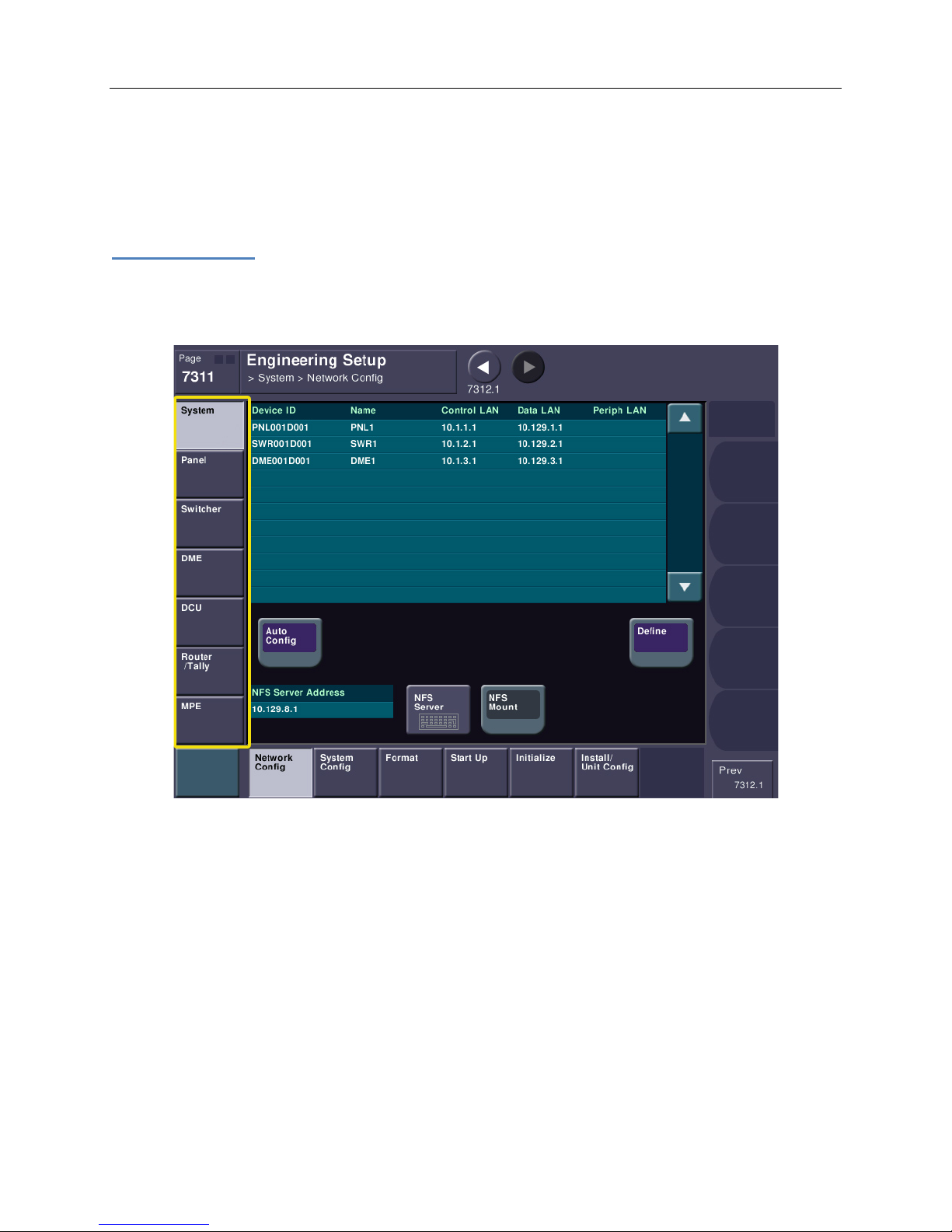
On the menu, please find and press the ENG SETUP button. Now, let’s look at the actual touchscreen
portion. On the left side are the major groups. You’ll see SYSTEM, PANEL, SWITCHER, DME, DCU,etc.
Please remember that the way the engineering setup menu is laid out is by device function. This means
that items under the SYSTEM section are settings that affect the whole system. Items in the PANEL
section only affect settings that actually occur in the panel processor. Items in the SWITCHER section
only affect settings that actually occur in the switcher processor. Because of the way it’s organized,
every once in a while you’ll have to change things in two different places.
pg. 34
Page 35
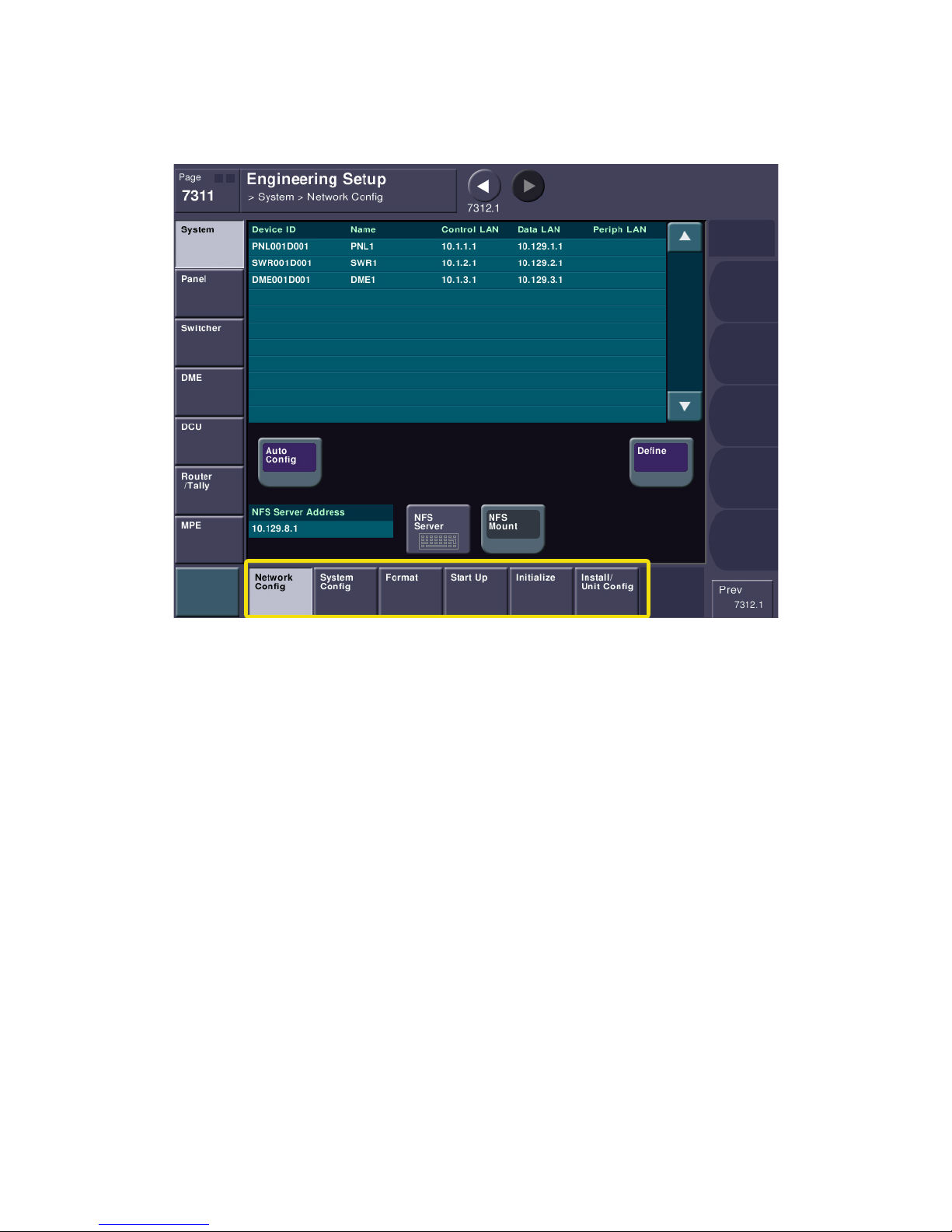
On the bottom portion of the touchscreen are the individual sections that can be changed for each
Group. For instance, on the left, please select the SYSTEM group. You will then see the bottom row
change and show you items like NETWORK CONFIG, SYSTEM CONFIG, FORMAT, etc.
pg. 35
Page 36
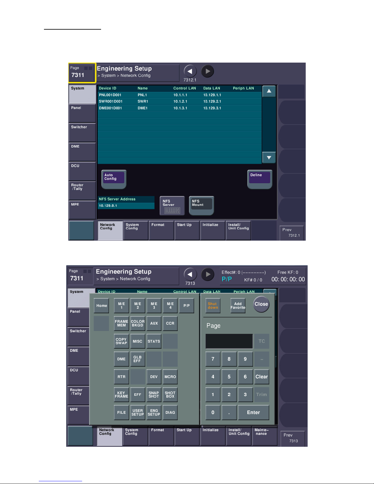
Menu Page Numbers
At the very upper-left corner of the touchscreen you’ll see a box that says “Page” and it will have a 4digit number.
Press the Page button now. You will see a dialog box open. Type 7311 and press ENTER.
pg. 36
Page 37
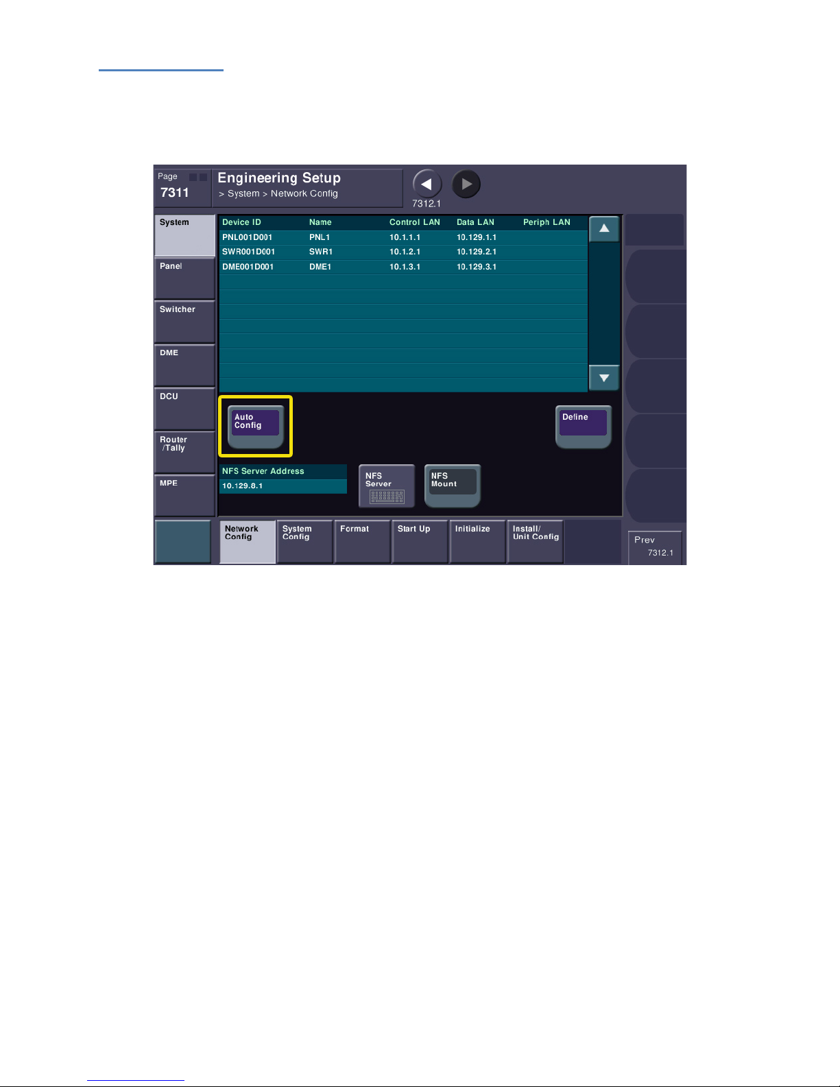
Network Config
This will take you to the ENG SETUP->System->Network Config Menu. We use this menu to make sure
everything is talking. This is also where we will see if all our Group and Unit IDs are set correctly.
Notice the purple buttons? Purple buttons are “execute” buttons. Most settings in the MVS menu are
immediate; you press the button and the setting changes. However, there are a few which need to not
be immediate, either because we need to confirm something, or MVS is waiting for several settings to
be changed and executed all at once.
Press the AUTO CONFIG button. You will get a dialog asking if you want to continue. Say OK. This
function will go out to the network and ask “who is there?” After a few seconds you should see
something like the following:
pg. 37
Page 38
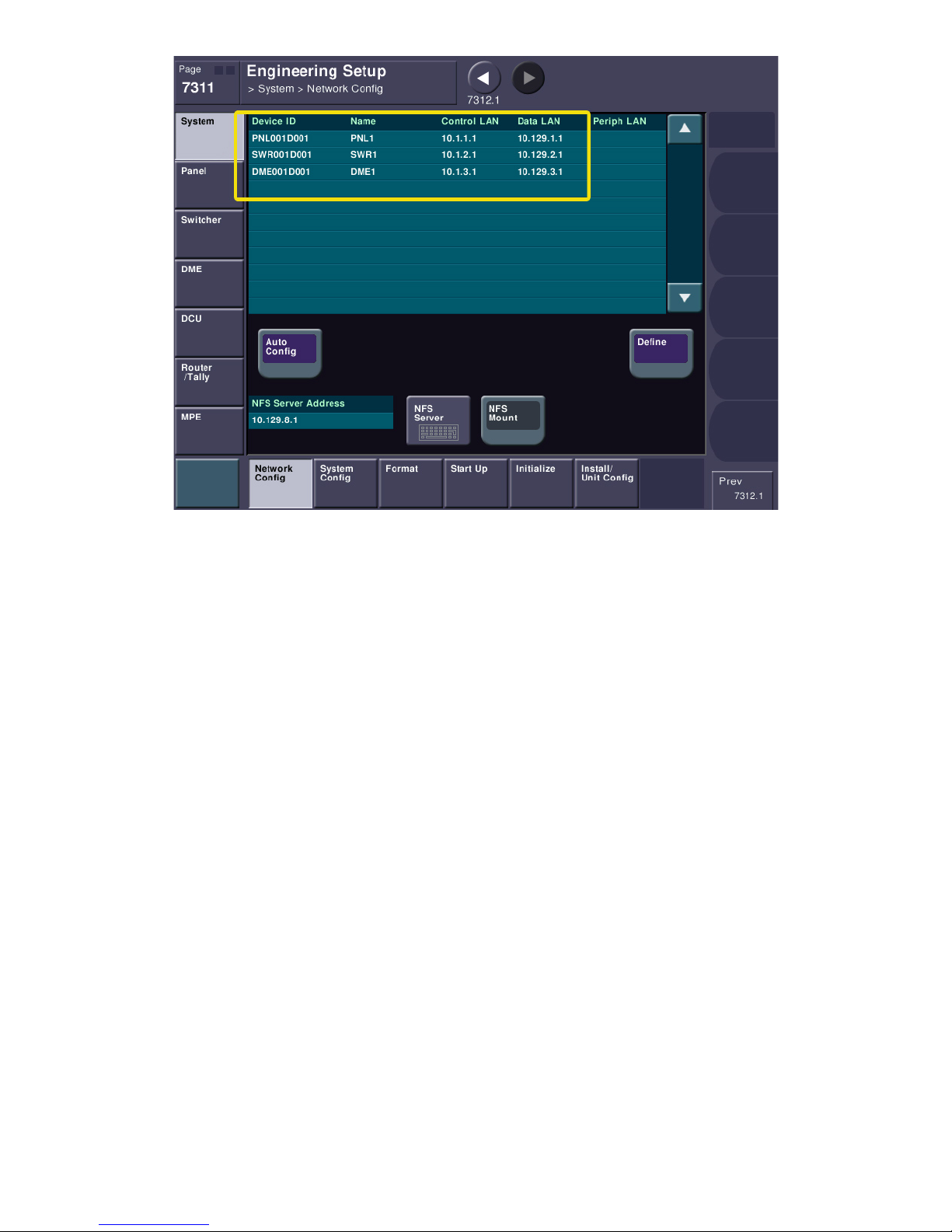
Notice this one shows a single Switcher (SWR1), one panel (PNL1) and one DME (DME1). By the way,
DME1 refers to the DME chassis (or in the case of the MVS-7000X for boards in the switcher), it does not
refer to the number of channels you purchased. DME1 can have up to 4 channels of video processing. If
you have channels 5-8, you should also see DME2. Please note that you will NOT see the DCU (Device
Control Unit) on this page.
If everything looks good and you see all the parts you paid for, please press the DEFINE button. If you do
not see all the parts you paid for, please check the network connecting cables and the Unit/Group ID
settings described above.
pg. 38
Page 39
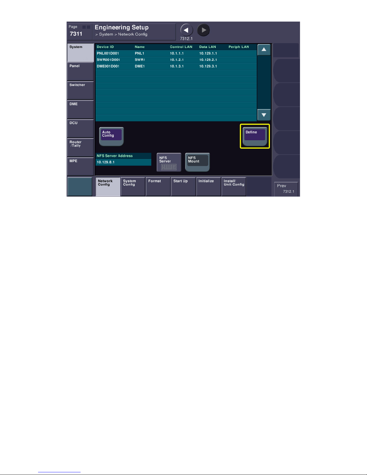
Pressing DEFINE will say “These are my components and use only these when the system starts.” This
keeps the system from trying to, say, talk to PNL2 when there isn’t one.
pg. 39
Page 40
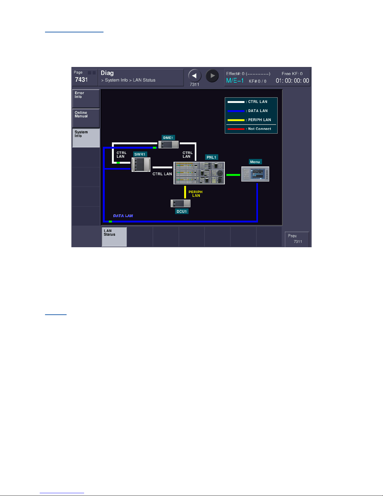
LAN Diagnostics
For fun, please press the Page button and enter the following menu page: 7431. This will take you to
the DIAG->System Info->LAN Status menu.
This graphically shows the communication between the components you just defined. Just as a side
note, blinking red lines are bad and mean communication is not occurring. This is a great menu to
troubleshoot communication errors.
Errors
The MVS system has a sophisticated internal diagnostic system. These diagnostics start from power-up
and run continuously while power is applied. If MVS detects an error in the system, you will see large
red letters spelling ERROR in the menu display.
pg. 40
Page 41
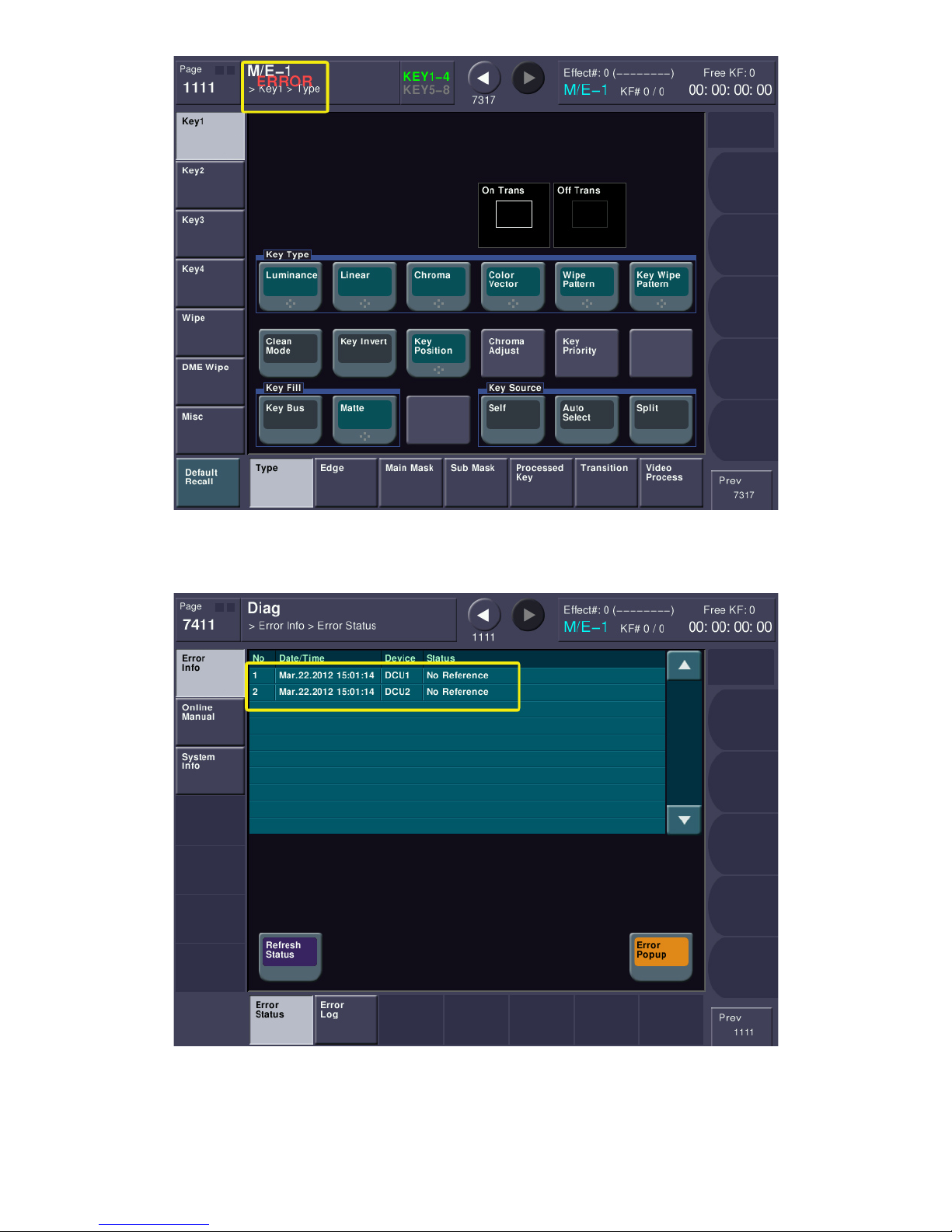
You can immediately go to the current error status by touching the word ERROR on the screen.
This error status shows that DCU1 and DCU2 are missing reference. Please be sure to keep the ERROR
POPUP button on. Turning it off will prevent the error notification from being displayed.
pg. 41
Page 42
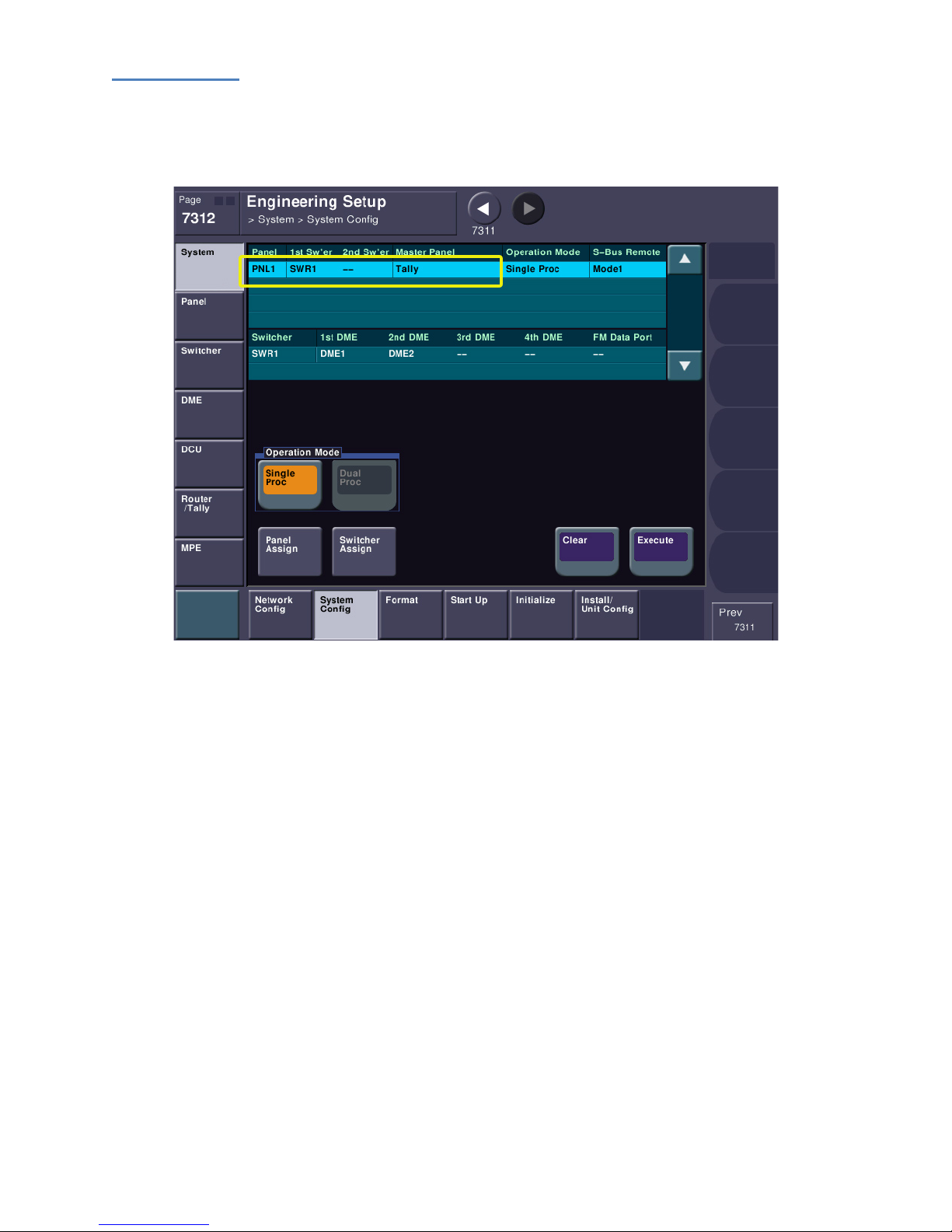
System Config
Now that we’ve told MVS what it’s supposed to be looking for, let’s continue to make sure all the parts
of the system will talk correctly. Please go to menu page 7312. This takes us to ENG SETUP->SYSTEM>SYSTEM CONFIG. Look at the top of the table.
You will see PNL1 on the left column. Column 2 should say SWR1, meaning that PNL1 is going to be
controlling SWR1. It is highly unlikely you will have two switcher chassis being controlled by a single
panel, which would show up under Column 3 as SWR2. We’re going to ignore the other columns for
now as these will be checked by our Field Service Engineer during your Install Check-Out.
pg. 42
Page 43
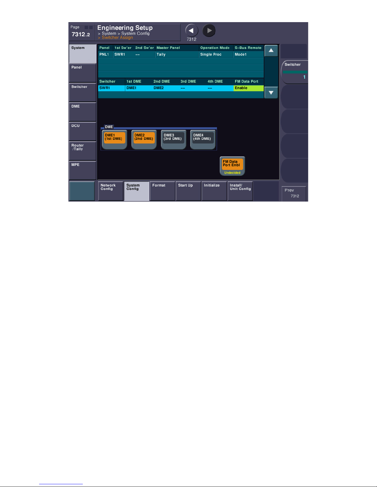
Likely, the only item we need to check is DME assignments and FM LAN. Please press the grey solid
button labeled “SWITCHER ASSIGN” (grey solid buttons are either shortcut buttons that take you to
another menu or sub-menu buttons). You can also just enter menu page 7312.2 (the decimal denotes a
submenu). This menu will let us “attach” DME chassis to a certain switcher processor. Towards the
bottom of the screen, make sure DME1 (1
8) also press DME2 (2
nd
DME). You cannot assign more than 2 DME chassis to a single switcher. The
st
DME) is lit and if you have a second DME chassis (channels 5-
other DMEs (3 & 4) are only there if you had a second switcher (SWR2) on the LAN.
Lastly there is a button labeled “FM Data Port Enbl”. In the LAN wiring section you should have
connected an Ethernet cable to the FM DATA RJ-45 and connected it to the Ethernet switch that you
marked DATA LAN. If you did this, please turn on this button. This will speed up Frame Memory
communication. If you did not hook this cable up, please do so and turn on this feature. DO NOT turn
on this button without the cable hooked up. You will not be able to load Frame Memory stills or clips.
Look again at the above menu. The FM DATA PORT ENBL button has text that says “Undecided.” Also in
the upper table, the FM Data Port setting is Enabled but highlighted in Yellow. This means that these
changes have not yet been implemented. Please return to menu page 7312 and press the EXECUTE
button. This will finalize the changes.
pg. 43
Page 44
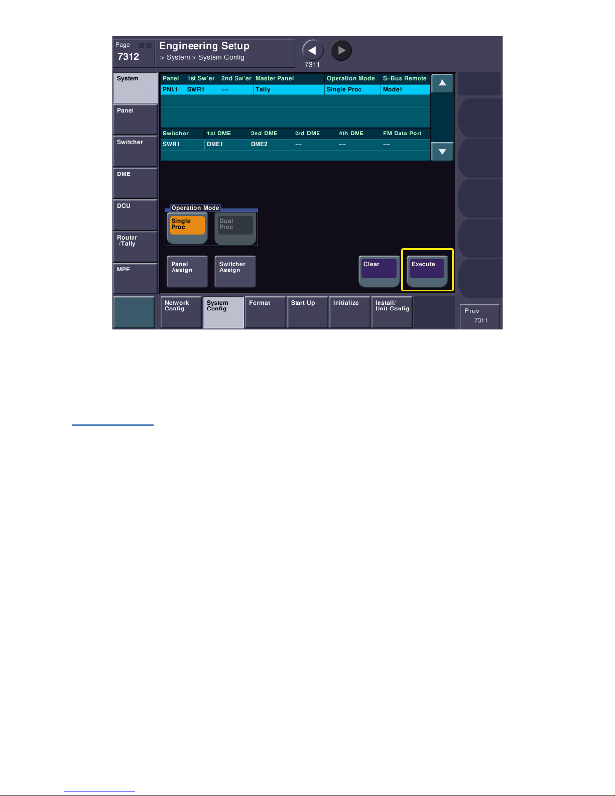
It is beyond the scope of this document to setup a complex system with multiple panels and/or switcher
processors. If your system is more complex than a standard one processor, one panel please contact
your Sony Account Manager and they will put you in touch with someone that can help configure more
complex systems.
Signal Format
Next, let’s make sure the video signal format is correct for your facility. Please jump to menu page 7313.
On the left table, you will see any panel(s), switcher(s) and DME(s) programmed to be on your system.
See why this has to be set up in order? If the switcher didn’t know what to expect, this screen wouldn’t
work.
pg. 44
Page 45
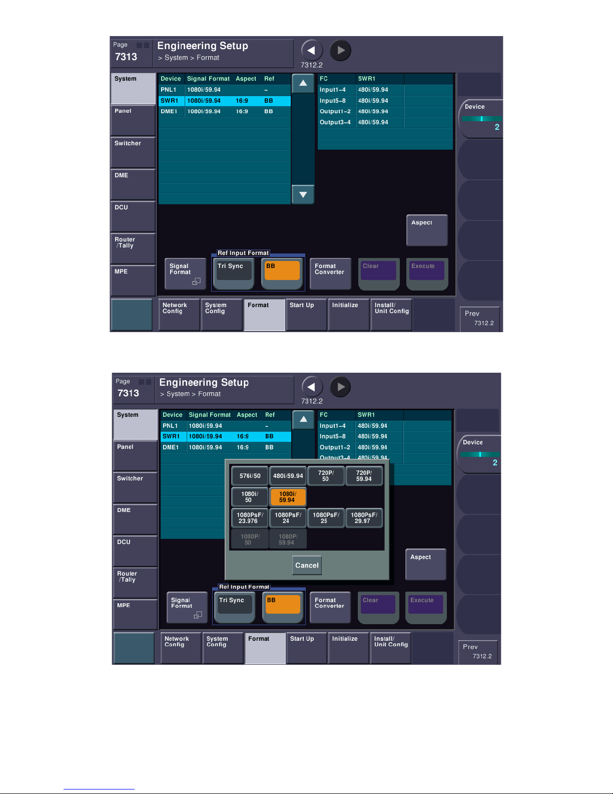
On the left table, please select SWR1. Below, please press SIGNAL FORMAT. This will bring up a popup.
Please select the video format you will use (which will likely be 480i/59.94, 720p/59.94 or 1080i/59.94.
If the only formats available to you are 576i/50 and 480i/59.94 (and you need HD) then it is likely your
Multi-format license keys have not been installed. Please contact your Sony Account Manager for
assistance.
pg. 45
Page 46
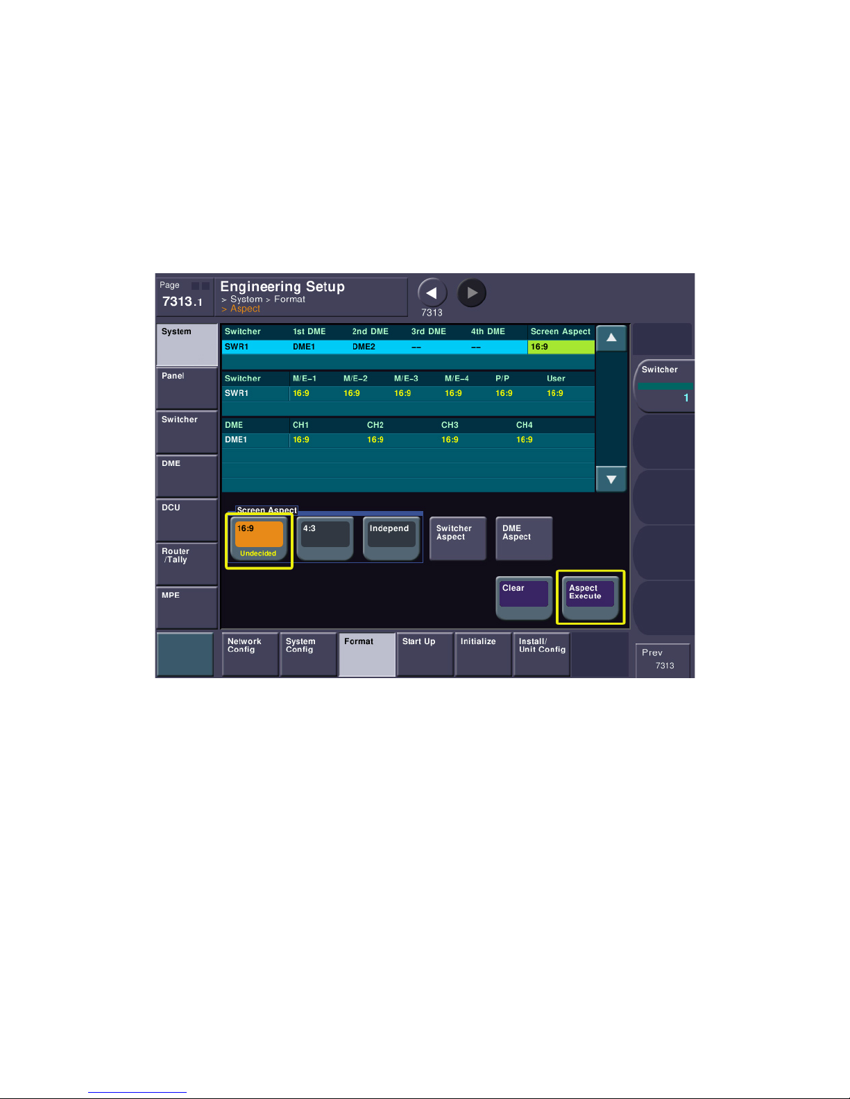
You will see that if it was necessary to change the format, the column marked “Signal Format” is in
yellow. This means you’ve selected it, but not executed it. Don’t execute yet, we’re not finished! At the
bottom of the menu is a group box titled “Ref Input Format”. This is where you need to set whether you
are using Black Burst (recommended) or Tri-Level sync. As mentioned earlier in this document, Tri-Level
sync is only really needed for 24P production. You must use Black Burst if you have the internal format
converter board(s).
Please set each of your components to your house reference type and the same system format using the
above procedure. If it is different it will also show up as yellow. If you are in 480i, you will need to also
set your aspect ratio (obviously, HD should be 16:9). To set, press the ASPECT button.
Just select one in the “Screen Aspect” group and everything will be set. If you change something on this
page, you must press ASPECT EXECUTE before returning.
If you set your aspect ratio, please go back one menu to FORMAT. You can either use the “web browser”
forward and back buttons at the top of the screen or you can just press FORMAT at the very bottom to
jump back to the main level. You can also jump directly back to menu page 7313.
pg. 46
Page 47
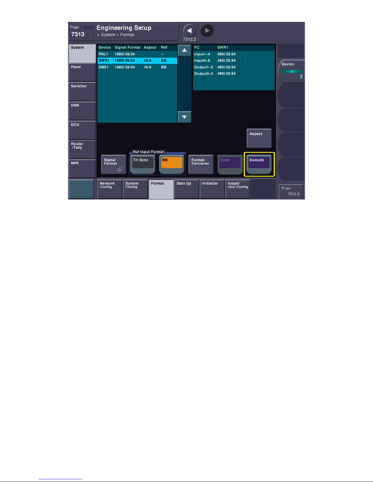
At this point, if you made any signal format changes (some items will be in yellow), press the EXECUTE
button to save those changes. It will warn you that the system will restart. This is normal. Please say
OK. When the system comes back up, we should be in the correct operating format. To check, go back
to menu 7313 and see if everything is set to the correct format and reference type.
pg. 47
Page 48
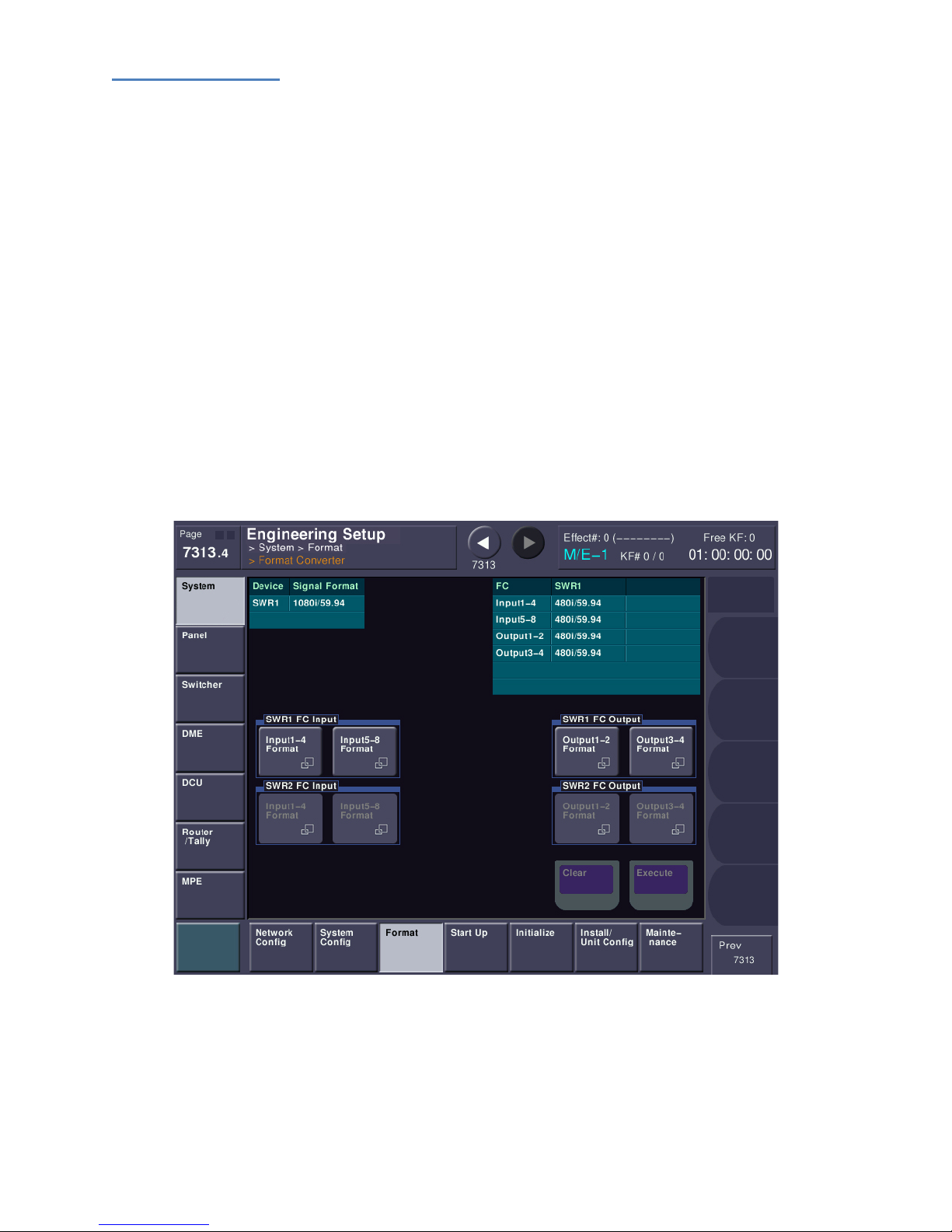
Format Converters
If you have format converter cards, we need to now set their input and output formats. If you have a
MVS-8000X you can have up to two format converter cards. The MVS-7000X supports a single format
converter board. The system will recognize how many cards you have and, in the right column, you will
see Input1-4, Input5-8 (and if you have two boards) Input9-12 and Input13-16.
It is important to note that the input format (what the switcher expects to see) is set in blocks of 4
format converter (FC) channels. This means if you have a single board you can set FC Inputs 1-4 to
accept 480i and maybe the other inputs 5-8 to accept 720p. Or they can all the set to 480i. It’s your
choice. Since an MVS-8000X can accommodate two format converter boards, you may also see Inputs
9-16, which can also be set in blocks of four.
You can also set two different types of output formats. Outputs 1-2 and Outputs 3-4 can be set
independently of each other. Please note that outputs 3-4 are only active if you have purchased 48
outputs in the switcher.
To change the input or output type of the format converters, press the FORMAT CONVERTER button.
Next, select the input converter block you want to change and set its input format. You can also set the
output format block, similarly to how you set the input block(s).
Press EXECUTE to set the format converter signal formats.
pg. 48
Page 49
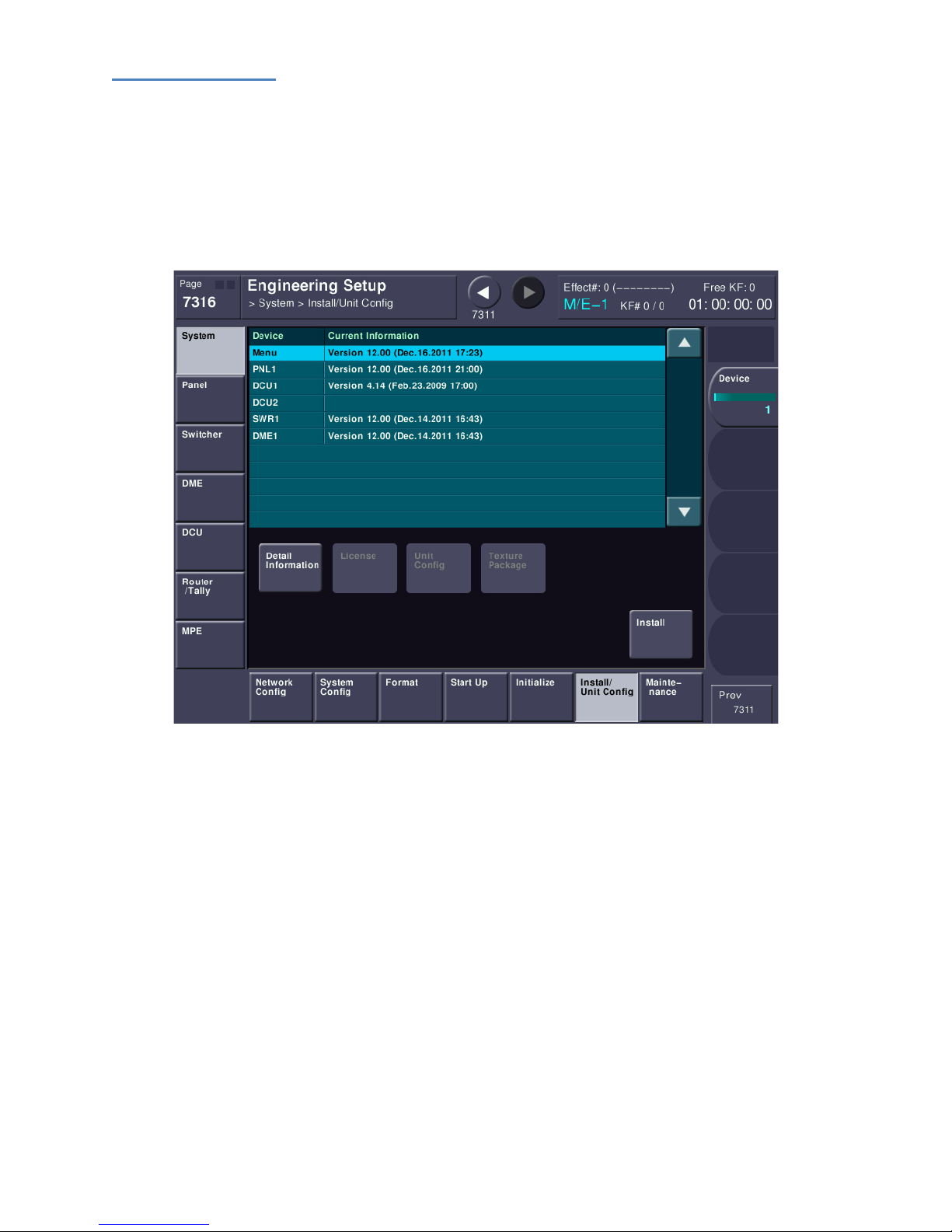
Software Versions
Let’s quickly jump to menu page 7316. This is the ENG SETUP->SYSTEM->INSTALL menu. This is where
you will install new software. It is also a page that shows the major software versions reported back
from each chassis. We are looking at this page to see if DCU1 reports back a software version. If you
see a software version on DCU1, then it’s communicating correctly. If you do not see DCU1’s software
version, please verify all the correct connections as discussed earlier. Because this screen reads all
chassis’ software versions, this is another great place to look for communications problems. If a
software version is reported back, it’s usually a good sign of normal communication.
If you ever have trouble and call Sony Service on the phone, one of the first things they’ll ask you is what
software version you have installed on each component. By the way, it’s common to have mis-matched
software versions between different switcher components.
Now, we’re going to skip the rest of the setup sections on the bottom as they will be covered during
your Install Check Out.
pg. 49
Page 50
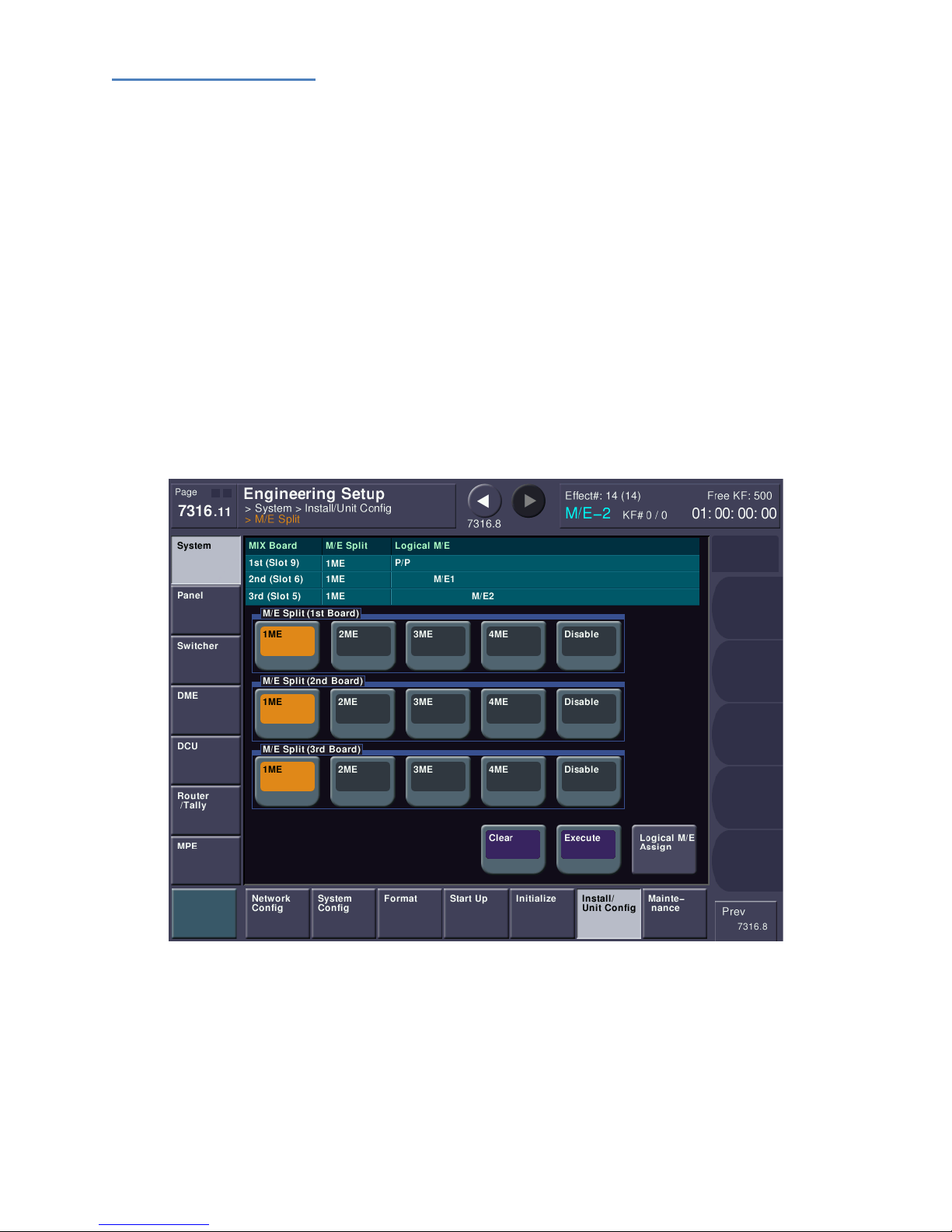
MVS-7000X FlexConfig
The MVS-7000X can have up to 3 physical M/E boards in its chassis. Each of those M/E boards has 8
keyers. Exclusive to the MVS-7000X is a feature called FlexConfig, which allows the logical partitioning
of those physical M/E boards and keyers.
First, you need to find out exactly how many physical M/E boards were purchased in your switcher, and
you also need to look at the number of M/E banks on the control panel. If they match (i.e. you
purchased three M/E boards and you have three M/E “stripes” on your panel (for three full M/Es), then
you can move on to the next section.
However, if you have a different number of physical M/E boards than you have control panel M/E’s,
then M/E resources need to be allocated in the system menu.
The FlexConfig feature was very likely discussed both with Engineering and the switcher operators prior
to the sale. It is recommended that you consult with those individuals prior to partitioning the M/E’s, as
described below. However, partitioning is not a permanent process and is easily changed.
Please jump to menu page 7316.11.
This menu is where FlexConfig is configured. The example above shows that each physical M/E board
has been assigned to a single logical M/E in the switcher. The first board in slot #9 is assigned to P/P, the
second board in slot #6 is assigned to M/E 1 and, finally, the third board in slot #5 is assigned to M/E 2.
If you purchased only two boards, then the bottom row would be unavailable. Similarly, if you
purchased only a single physical M/E board, then only the first row would be available.
pg. 50
Page 51
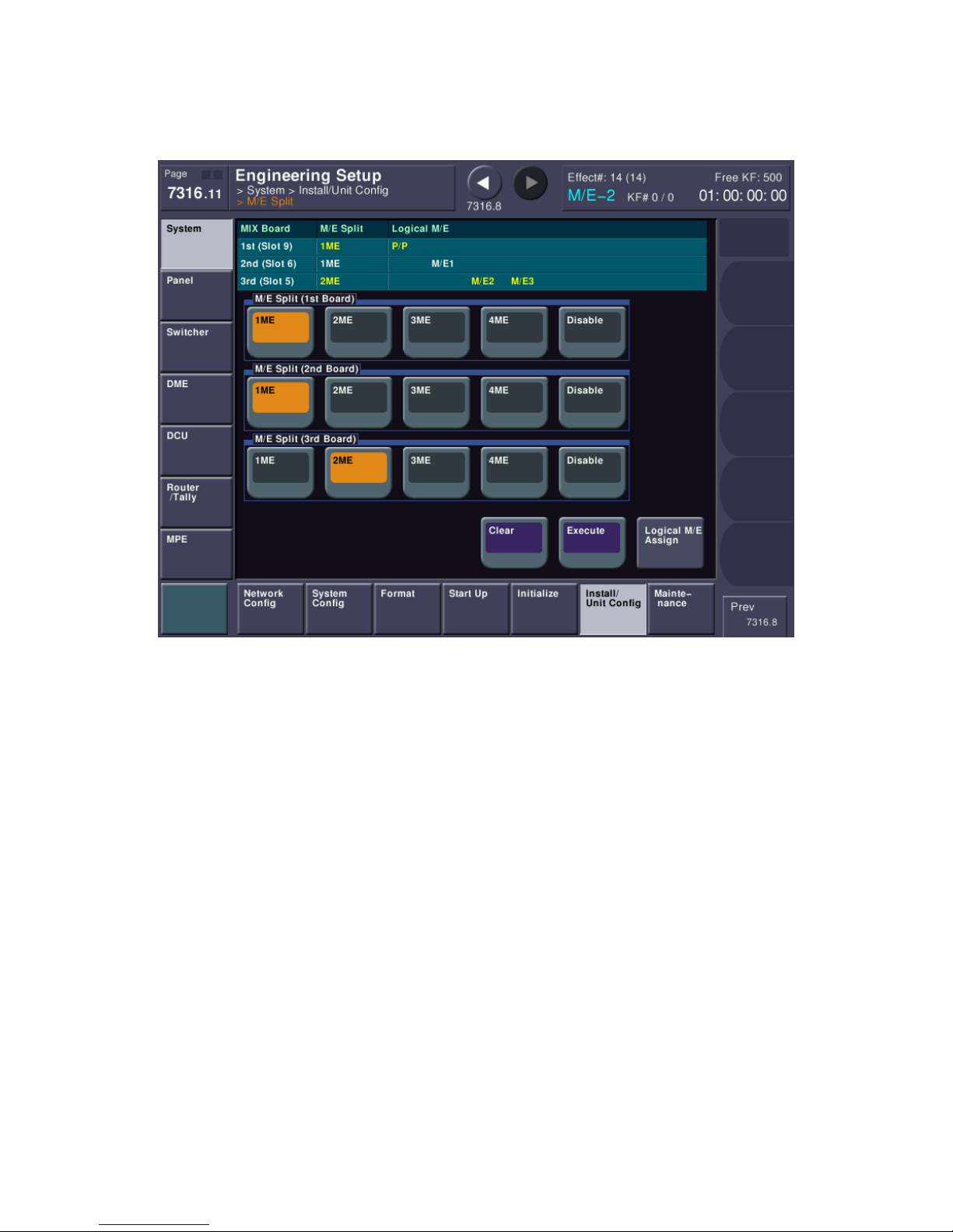
As you can see, each physical M/E board can be run in either “1 M/E” mode or divided into two or more
logical M/E partitions. For example, below shows a menu where the first and second boards are running
in 1 M/E mode, but the third board which was used exclusively for M/E 2, has now been divided into
two logical M/Es consisting of M/E 2 and M/E 3.
In this mode, P/P and M/E 1 have 8 keyers, but M/E 2 and M/E 3 will have 4 keyers each. It is very likely
the assignment of these resources as already been discussed between Sony, your engineering
management and your facilities switcher operators.
pg. 51
Page 52
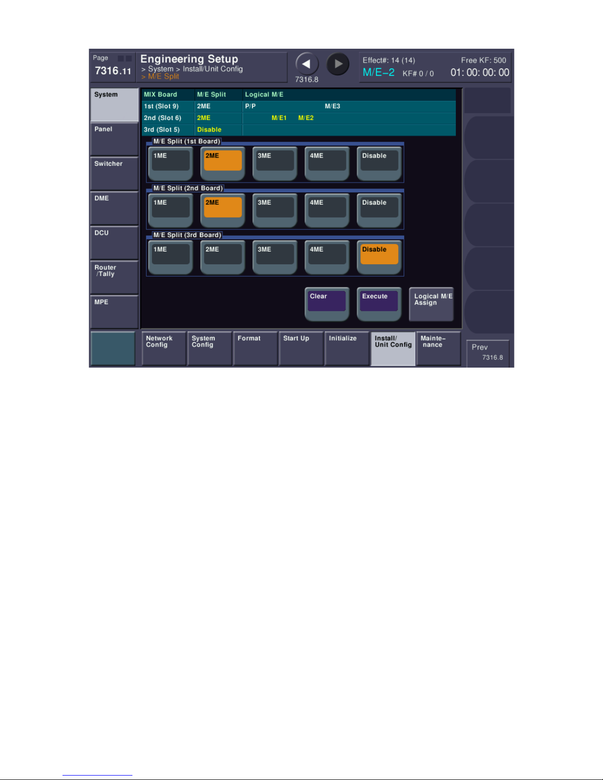
The example above shows having only two physical boards installed in the chassis but having a 4 M/E
control panel. In this case, each of the available boards has been divided into two logical M/E partitions.
Each M/E in this scenario will have 4 keyers.
pg. 52
Page 53
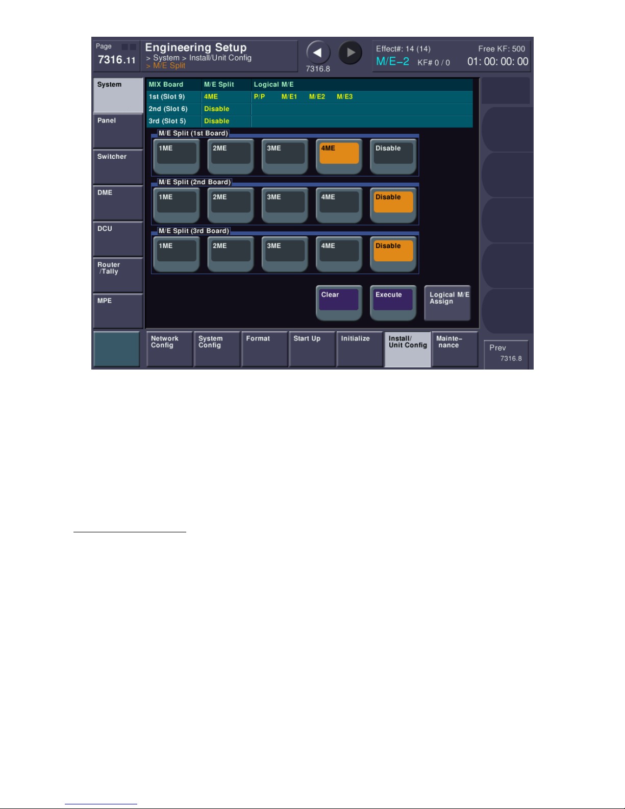
Finally, the example above shows having only one physical boards installed in the chassis but having a 4
M/E control panel. In this case, each of the available boards has been divided into two logical M/E
partitions. Each M/E in this scenario will have 2 keyers.
Please note that a single M/E board being split into more than 2 partitions (3 M/E or 4 M/E mode) is
contingent upon only a single physical M/E board being installed in the chassis.
After you make any changes to the M/E modes, you will need to press the EXECUTE button, which will
cause a system reboot.
A Note on using 8 Keyers
Sony control panels, by default, are shipped from the factory programmed and labeled for four keyers
per M/E. If you are running any M/E’s that have 8 keyers you will not be able to control keys 5-8 until
the switcher is properly programmed and the panel’s button labels have been updated. Details on how
to change control panel buttons and their underlying function are beyond the scope of this document
but can be found in the user guide. Your Install Check-Out (ICO) technician or your operator trainer can
also assist you in making these panel changes.
pg. 53
Page 54
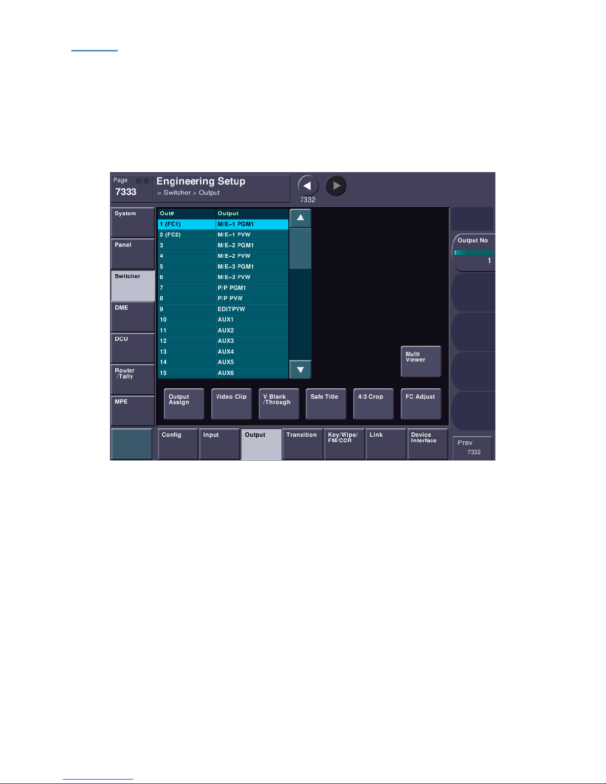
Outputs
The next setup item we need to configure are the OUTPUTS. Why outputs before inputs? Well, we
need to see a working output on a monitor to see if we have working inputs.
Please go to menu page 7333 (ENG SETUP->SWITCHER->OUTPUT. In the table, you can see what has, by
default, been assigned to each output connector on the back of the switcher. If you have already
hooked up a monitor to an output and that output has been assigned as “P/P OUT1” (by default it’s
Output 7) then you’re set.
If your physical connection does not match up, let’s set it. Please press OUTPUT ASSIGN.
pg. 54
Page 55
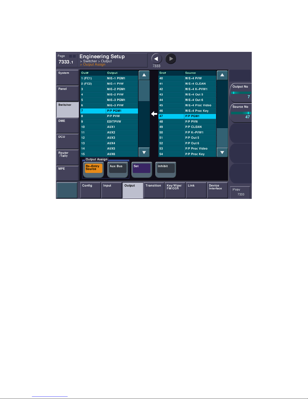
You can see now we have two tables. Notice the Arrow in the middle between the two tables. This type
of “flow” is repeated all over the MVS menu. It’s simply saying that whatever you choose on the right
table will make its way into the left table. In this case, the right table as all the sources that can be
assigned to a physical output.
There are two types of output signals: Re-Entry Sources and Aux Buses. Re-Entry sources are signals
that have been created or modified inside the switcher. These would be things like “P/P PGM1” or “P/P
PVW”, etc. Aux Buses are the output of the 48 internal Aux Buses in an MVS system. Every MVS system,
no matter how large or small, has 48 Aux Buses. You just have to have purchased enough outputs to get
them out of the switcher. In fact, there are WAY more signals floating around the switcher than you
would ever have outputs. It’s analogous to a 512x128, fully populated, routing switcher. You may have
512 inputs to your router but you can only get 128 out at a time. A switcher works a lot like that.
As mentioned in the beginning of this document, there are factory defaults to outputs. For instance, if
nothing has been changed you’ll see that OUT 7 will be P/P PGM1, which is PGM by default. To make
things easier, you could just ensure that you connected your monitor to Output 7 on the back of the
switcher. If, however, you wanted your program monitor on OUT12, just select “RE-Entry Source” at
the bottom, then scroll the right table to find “P/P PGM1” then scroll the left table until Out 12 is
highlighted, then press the Purple SET button and now OUT12 is showing “program”.
pg. 55
Page 56
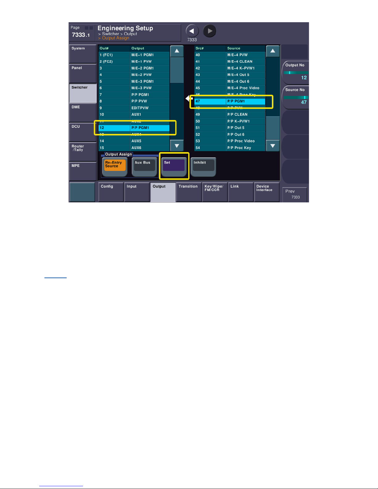
Notice there is no limit to how many times I can route the same signal to different outputs – with one
exception. Aux buses can only be routed to one output at a time. In other words, it’s not possible to
have Aux 1 on both Out 10 and Out 11 at the same time. If you need an aux bus or two to have dual
outputs, consider using outputs 23-24 and 47-48 as they have dual output connectors (outputs 47-48
are only active if you have 48 outputs).
Inputs
Next, let’s set up an input or two. Please go to menu 7322 (ENG SETUP->PANEL->XPT ASSIGN). Notice
this took me to the PANEL section. Why the panel section? Aren’t inputs part of the switcher? Well,
yes and no. The “video” side of inputs, like level adjustments, whether ancillary data is passed, blanking,
etc. are set in the switcher, but we are really talking about “mapping” an input to a panel button. That’s
why we are in the panel section.
Mapping can be a rather complex topic, so bear with us. The MVS system has 15 different mapping
tables. This means we can have different parts of the switcher with different button mappings. That
being said, just because we can have different parts of the switcher mapped differently doesn’t mean
that most people actually map them differently. We are going to concentrate on two different tables:
The Main Video/Key pair assignments and “Table 1”.
pg. 56
Page 57
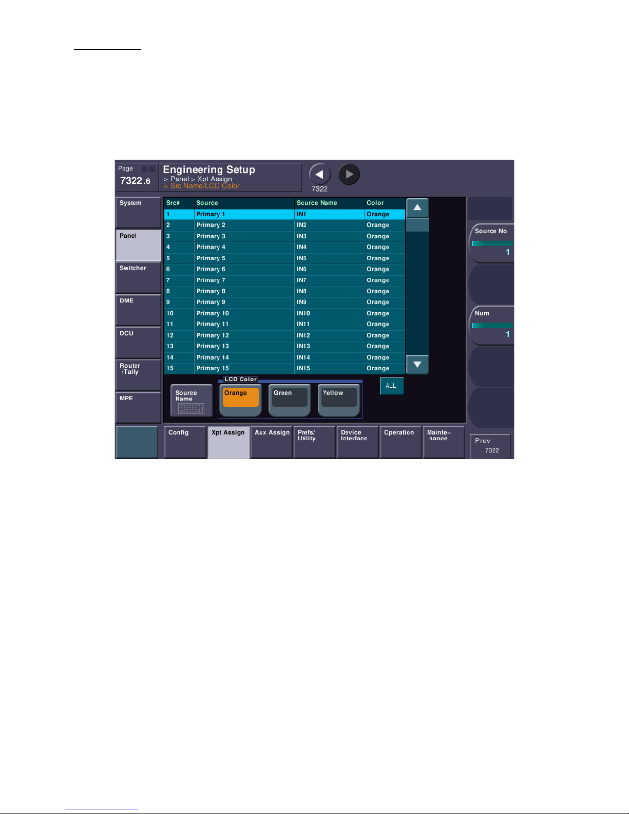
Naming Inputs
First things first. Let’s name the inputs. It will make things far easier later. Please press the “Src
Name/LCD Color” button which will take use to menu 7322.6. This table represents all the inputs, both
physical and other sources in the switcher like Frame Memory outputs. Select your first input you’d like
to label and press the “Source Name” button, below. Notice it has a small picture of a keyboard. That
just means when you press that button a virtual keyboard will come up on the screen. (Tip…. If you like
a real keyboard, you can connect a USB keyboard to the USB port on the panel).
Before you type in a name, there are a few rules and tips:
• A name must be 8 characters or less.
• The LCD displays have two lines. If you use 4 characters there is an automatic carriage return to
line 2. When you have an automatic carriage return, don’t put in a space or you won’t see your
name correctly. For instance, let’s say you had a source you wanted to label “ROUT 1”. You
need to enter it as “ROUT1” without any space between the ROUT and the 1. On the display
ROUT will take the first line and 1 will be centered on the second line.
• If you have a name that you want less than 4 characters on the first line and you also want a
second line (for example, CAM 1), don’t use a space as MVS will see a space as the fourth
character and your “CAM” will be left justified and the “1” will be nicely centered below it.
Instead, use the pipe ( | ) symbol, which is SHIFT \ (Shift and backslash right above the enter
key). The pipe symbol tells MVS to immediately carriage return. So to get something like CAM
1, both lines centered, you need to enter the name as “CAM|1”. Try it, you’ll see.
• There is a great shortcut for naming sequential inputs. Let’s say you have 7 cameras and I don’t
want to type “CAM|x” seven times. This trick only works if the inputs are next to each other. In
the naming table, select the first input let’s say Input 3), next move knob #3 on the right side of
the menu display until you’ve highlighted all the “cameras” you want to name. With all your
cameras highlighted, press the keyboard button and enter the first name “CAM|1” then press
enter. It will increment the rest for you! There is one catch… You can only auto-name a single
pg. 57
Page 58
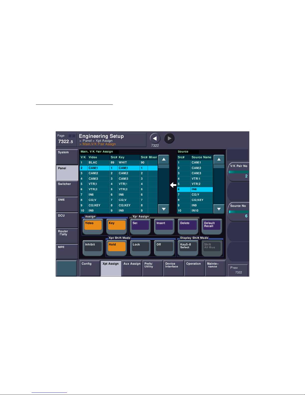
end digit. If you have 15 cameras, you’ll have to do CAM1-9, then do it again this time start with
“CAM|10” and it will auto-name CAM 11-15.
• If a source has two characters or less, the display will show very large text. This is handy when
you want to identify a camera as just “1” instead of “CAM 1”.
Lastly, on each input you can change the color of the LCD. You have a choice of Orange, Green and
Yellow. This is typically set by the operators, as are the names.
Please take a moment to label any sources you may have wired into the switcher. For now, avoid
changing the names of the internal sources and only rename physical BNC inputs.
VIDEO/KEY and Table Assignments
Next, we need to set the Main Video/Key pair assignments. Think of this assignment as the “back” of a
patch-panel. Please press “Main, V/K Pair Assign” which will take us to Menu 7322.5.
The left table is showing us what are called Video/Key (V/K) pair assign numbers. These numbers aren’t
really important to the end user, but each of these pairs needs to be accounted for. Again, think of the
back of a patch panel… we need to set what’s “normal.” The right table is a combination of physical
inputs (BNC connectors) in the switcher and other internal signals. This table can be quite large. If this
is a brand-new switcher fresh from the factory, these tables will be initialized. If not, let’s clear the table
out. Please press the purple “Default Recall” button and say YES. We have now set the Main V/K (or the
back of our fictitious patch panel) to factory default. Notice that V/K pair #1 is Black. V/K Pair #2 is
CAM1, V/K pair #3 is CAM2, etc. (the names are for examples only. Yours will likely say “IN1”, “IN2”, etc.
Please take a moment to scroll the left table and see what’s there.
After you’ve had a chance to look at the left table, take a look at the right table of sources that can be
placed in the Main V/K pair table. A couple of notes here: You will find all the primary inputs here (if it’s
pg. 58
Page 59
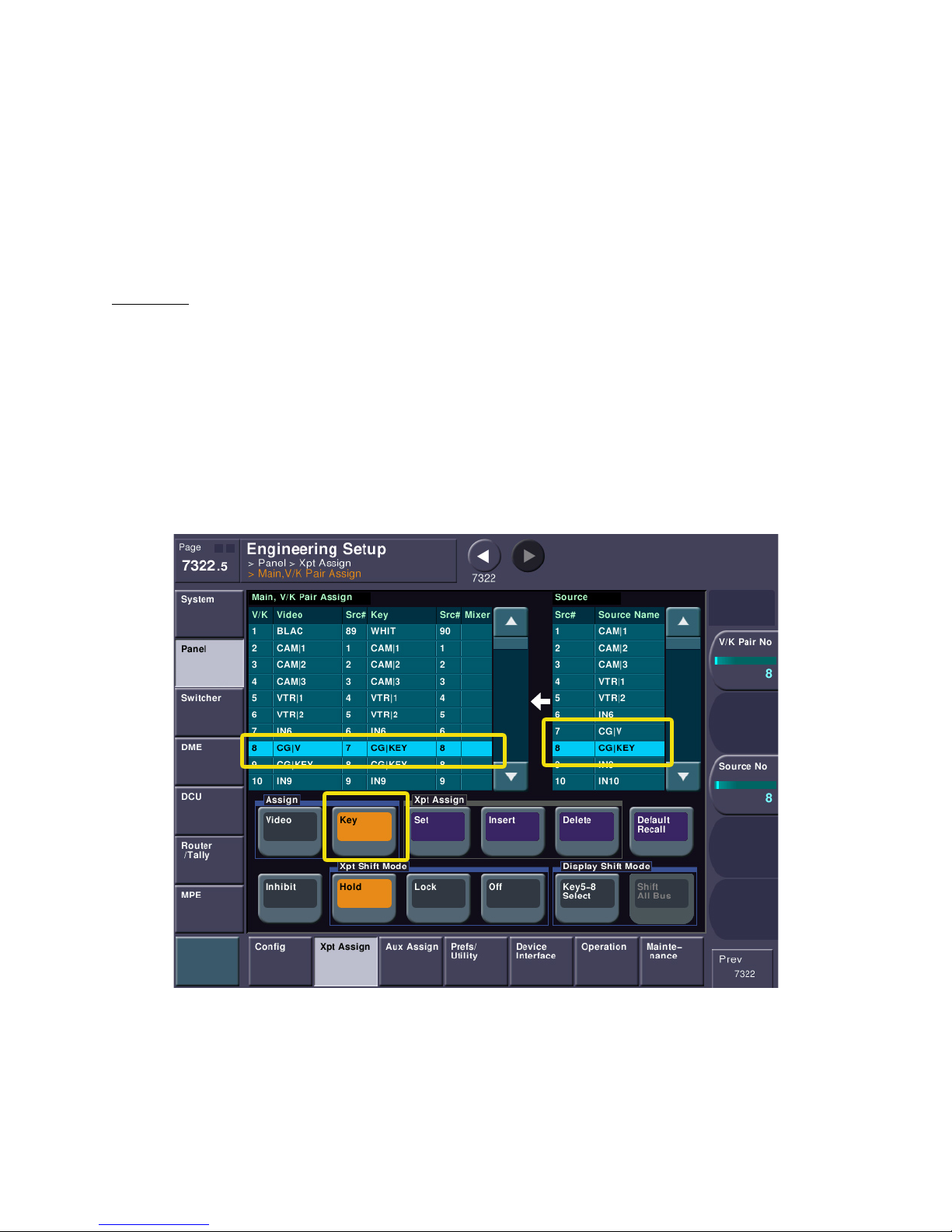
a 8000X you’ll find inputs 1-144, if it’s a 7000X you’re find inputs 1-80). But you’ll also find a lot of other
items like Color BKGD 1 and 2. You’ll also find BLACK and WHITE (we’ll get to WHITE later). If you have a
8000X, the Premium Inputs will be listed. Both the 7000X and 8000X will also have their Format
Converter input channels. Finally, you will find all the other internal signals, like PGM, ME PGM, etc.
that you may want to assign to a button. In a nutshell, if it’s a signal that you want to punch up on the
main switcher or an aux bus, you’ll find it on the right-hand source table.
So, let’s assume you’ve wired a few inputs to IN01, IN02 and maybe IN03. By default those are going to
be set on V/K pair #2, 3 and 4, respectively.
Key Signals
Also notice that, by default, the associated key signal is the same as the video signal. If you have a CG or
some other device that has a key signal, we need to tell the switcher which input to use for video and
which one to use for its associated key signal. Find the video input name in the left table that
corresponds with where the video from your device is wired and make sure it’s selected. In this
example, we’ll simulate this on Input 7 and Input 8, which are called “CG|V” and “CG|KEY.” Next press
the KEY button in the Assign group. Make sure only KEY is turned on, if both VIDEO and KEY are turned
on, turn off VIDEO. In the right table, please find the input you wired the KEY SIGNAL to. After you’ve
found and selected the key signal, please press the purple SET button. You should now see in the left
table the video coming from one input and they key coming from another input.
We’ve just set up a VIDEO/KEY pair. It is very likely that you will have “left-overs” in your left table. For
instance, if your video was input 7 and your key was input 8, you will likely still have a table entry that’s
seems to be treating the key like it was its own line. That’s ok and we can just leave it for now.
Normally, if a video signal had no associated key signal, like a camera, we wouldn’t really care. That was
before the invention of internal Digital Effects (DME). Since the DME’s video input is really the output of
pg. 59
Page 60
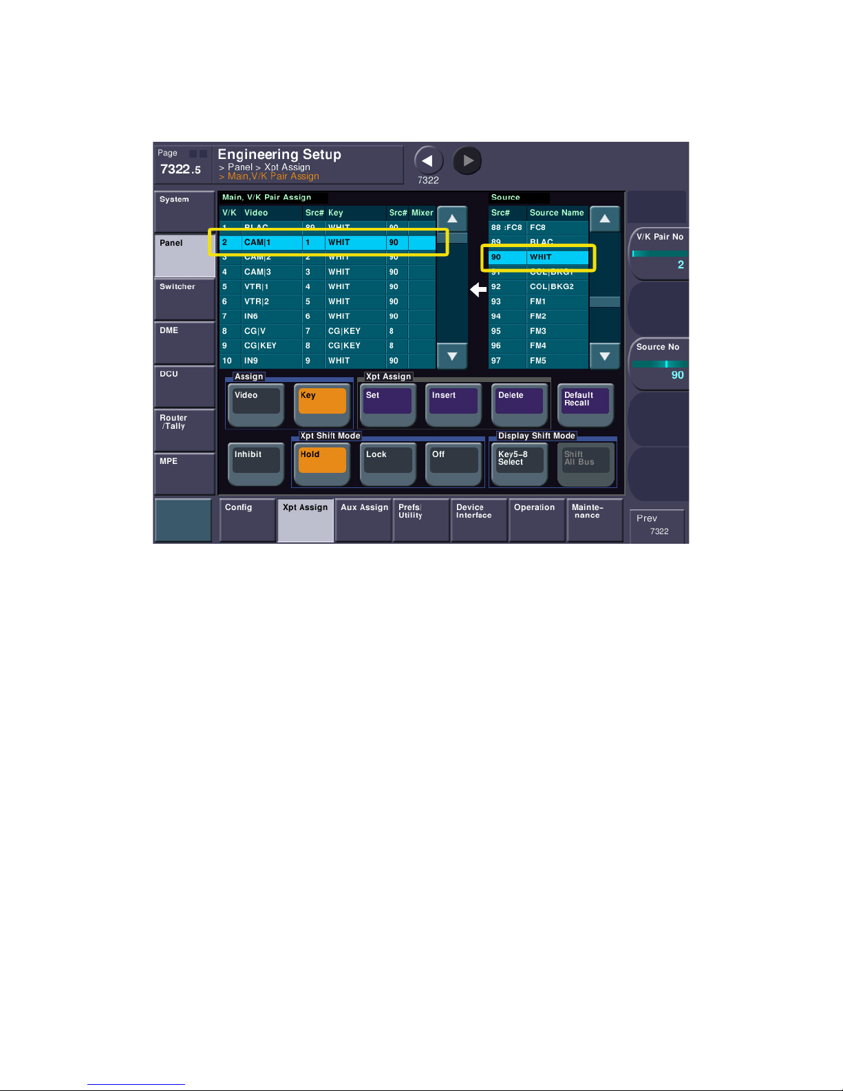
the keyer, we have to be a bit tidier. We need to assign a full field white key signal to any video source
that doesn’t specifically have an associated key signal. Pick an item from the left table that isn’t going to
have a dedicated key signal (like a camera) and perform the same procedure as above, except this time
look for the source WHITE in the right table (as of software version 12, it is source 90).
This will tell the keyer that the keyed video should replace the background completely whenever it’s
keyed. Don’t worry, if a bona fide video with matching key is on the keyer, both the keyer and the DME
will pass the true key signal, too.
The Main V/K Pair Assign area we are in is typically only accessed by engineers and not TDs, or switcher
operators. Once this section is setup, it is rarely touched unless something changes in the way the
switcher is actually wired – just like the back of the patch panel. However, the operators need to be
able to freely change where inputs appear on crosspoint buttons of the switcher. Therefore, there is
another section that allows this without changing video/key pair assignments. This section is analogous
to the front of the patch panel. It is quite normal for someone to make a patch on the front, but
unheard of to keep changing the “normal through” wiring on the back of the patch panel just to get a
different source patched. This same scenario works in setting up MVS.
Please jump back to menu page 7322 again.
pg. 60
Page 61
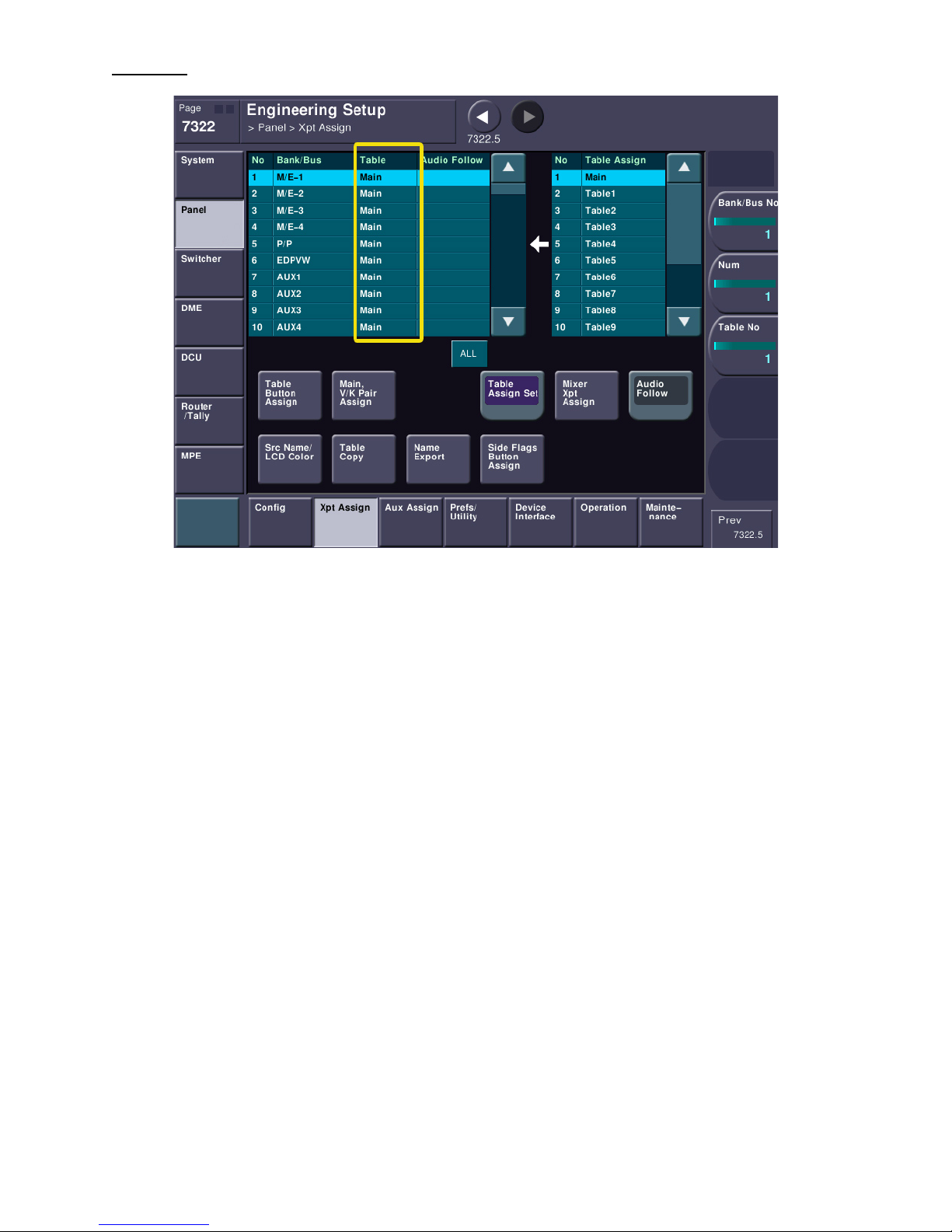
Sub-Tables
The left table is a list of all the parts of the switcher that can have crosspoint tables assigned. Typically
they are all going to be set the same. If this is a factory default, then they are all likely set to MAIN
(that’s the second column on the left table). We absolutely, positively DO NOT want them (any of them)
set to MAIN. MAIN is the back of our fictitious patch-panel. If we leave MAIN assigned, it means if an
operator wants to change a button they have to mess with the V/K pair assignments – or the back of our
fictitious patch-panel – a big no, no. However, if we set the switcher areas to use TABLE1 instead,
operators can freely change crosspoint mappings without changing the main table. Why? Because
Tables 1-14 are just pointers to the main table – the front of our “patch panel”.
pg. 61
Page 62
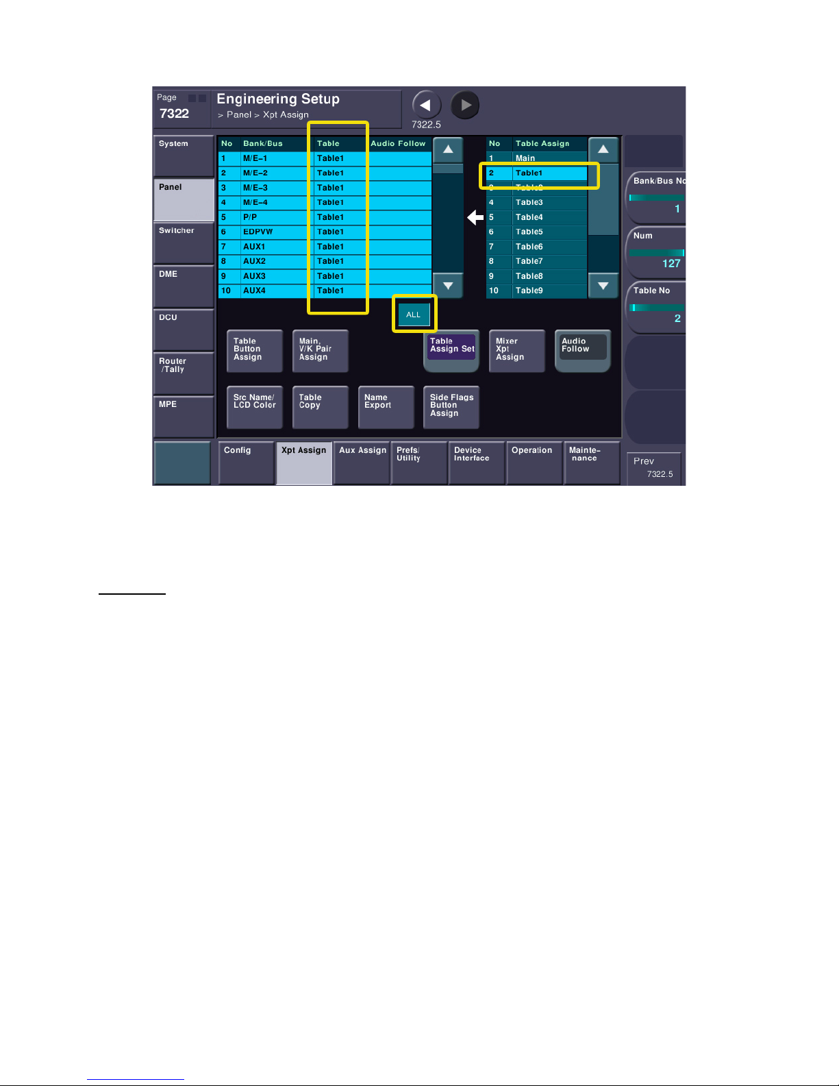
Let’s set the whole switcher to use TABLE1.
Please press the small “ALL” Button right below the left table. The entire table will now be highlighted.
Next, on the right table, please select Table1. Finally press the purple “TABLE ASSIGN SET” button.
Now, the entire switcher is using Table1 for mapping.
Table Copy
Just to make sure we are using the defaults and we are working with a clean slate let’s initialize Table1
so it matches the main table. Please press the TABLE COPY button. On the left side, please select the
bottom entry, MAIN. On the right side, please select Table1 then press the purple COPY button.
pg. 62
Page 63
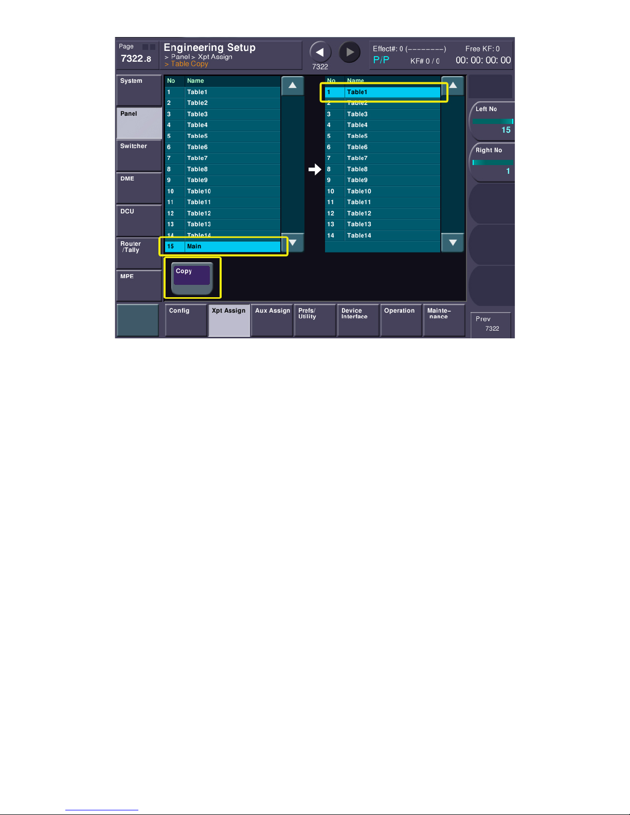
This has made Table1 exactly the same as Main.
Now, let’s change Table 1’s button assignments. This lets the operator move inputs to any crosspoint
button, but preserves your engineering settings in the MAIN V/K assign table.
pg. 63
Page 64
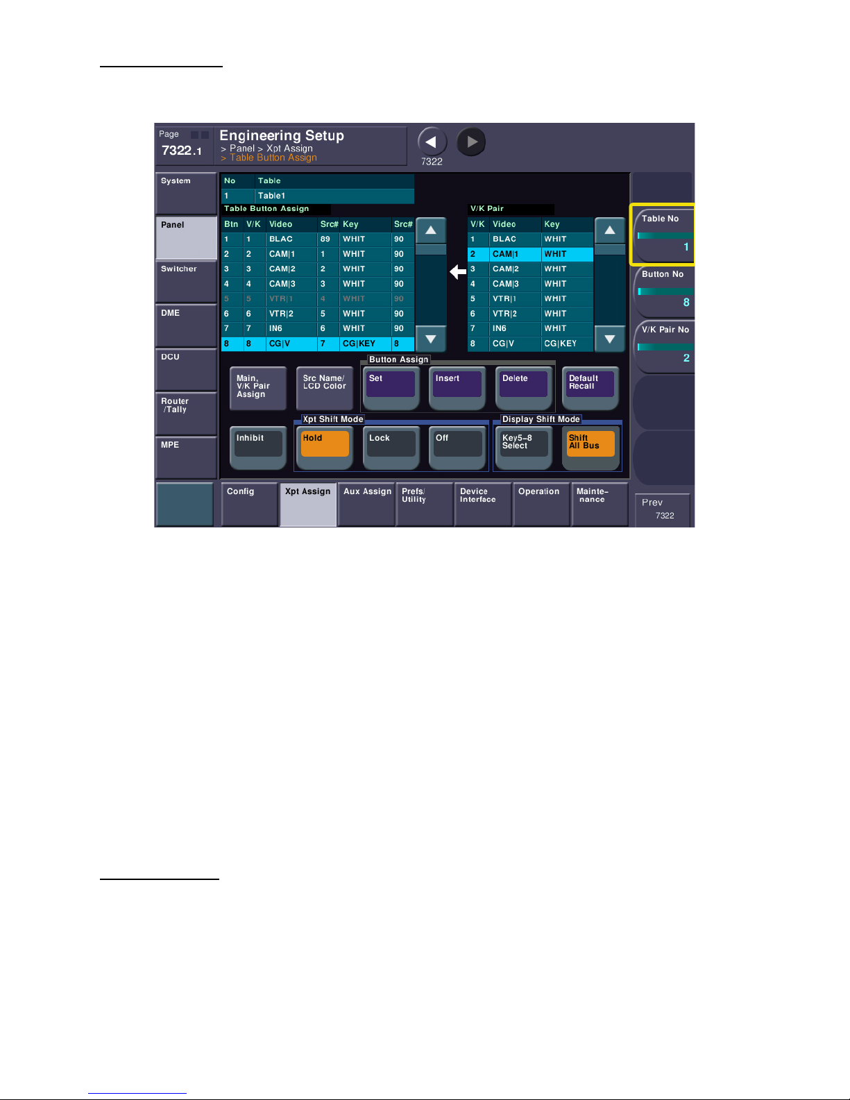
Table Button Assign
Please jump back to menu 7322 and select Table Button Assign.
This screen looks a lot like the MAIN table assign. First, be sure knob #1 is set to “Table 1”, since that’s
what we’re using everywhere.
The left table represents the actual buttons on the switcher panel. Button 1 is all the way to the left.
Button 2 is to the right of button 1 and so on. If your panel has 32 crosspoint buttons, then button 33
will be SHIFT + Button 1. If you scroll the lest table, you will notice the background color of the table
changes slightly to inform you that you’re working on shifted buttons. The right table is your
engineering MAIN V/K pair. The good news here is, when an operator wants to put the CG (which has
both Video and Key) to a button, they don’t have to worry about setting both the video and key, they
just select from the right table and the V/K are brought over automatically. Also, since Sub Tables
(TABLE1-14 are sub-tables) are always referenced to the MAIN table, any changes to make in the MAIN
table will trickle down to all the sub tables. Practice changing the location of your newly wired inputs
and place them on different buttons. Keep in mind if you use INSERT or DELETE, inputs may fall off the
panel and become inaccessible. When you’re finished it might be a good idea to return everything to
“normal” until everyone understands how this works.
A Word of Caution!
One BIG, BIG word of caution…. After the switcher is on-line or operators have done a substantial
amount of setup with button tables, avoid changing the MAIN table without a very good reason. All of
the operator’s effects store crosspoint data from the selected sub-table. Since all the sub-tables directly
reference the MAIN table, any changes made in the MAIN table might make effects work incorrectly.
For instance, let’s say you had CAM1 on Input 1 and you set Input 1 to MAIN table V/K pair #2. The
operator uses TABLE1 and sets your V/K pair #2 to button 10. The operator has many effects for the
pg. 64
Page 65

6pm news that will call up CAM1 (which is currently on button 10). All Sub-Tables reference the MAIN
V/K pair number! If the MAIN V/K pair is changed later to be Input 5 instead of Input 1 (where it was
originally set), there will be a big on-air problem. Remember, again, that sub-tables only reference V/K
pair numbers. They have no idea what is assigned to the V/K pair number. So if V/K pair #2 now points
to input 5 instead of input 1, every time the operator calls up an effect that needs CAM1, it’s going to
call up video coming from Input 5, regardless if it’s camera 1 or not!.
This goes back to the patch panel theory again. If the front of a patch panel is marked with sources,
people assume if they put a patch cable into the hole marked VTR1 it’s really going to be VTR1. If the
back of the patch panel has had cables changed but the front labeling hasn’t been changed…. See the
problem? Main and Sub tables work exactly the same way! For the same reason, you will also run into
this problem if you just move V/K pairs around. Again, once they’re set, leave them alone.
If you add a new source, it’s not necessary for the V/K pairs to all be sequential. Just put the new source
on the next open pair (or completely unused pair). For example, you had 6 cameras when you installed
this switcher and you put them on inputs 1-6. A year later you buy another camera, Camera 7. Don’t try
to move all the BNC connectors down one so all your cameras are next to each other. The same advice
goes for Main V/K pairs. Don’t move everything so all the cameras are next to each other on the “back”
of our fictitious patch-panel. Just find an empty or unused V/K pair and put the new source there.
When you tell the operators where the new source is on the V/K pair table, they can map it anywhere
and none of their existing effects have to be changed.
Please take the time to repeat the above procedures to set the rest of your wired inputs (whether they
are just video or have both video and key) into the left table. If you have just a few, it won’t take very
long. If you have already pre-planned all your 80 or more inputs and wired them up, it’s going to take
you a while!
Let’s Try This Out!
So, right now, if you hook up a signal that’s in the same format as the switcher (let’s say 1080i for now)
and you hook a signal into INPUT 1 on the back of the switcher, then press the second button from the
left on PGM-A (will be the second long row of crosspoint buttons from the bottom on the panel), you
should see your input signal on your monitor. If you don’t, please go back and check your settings
against this document.
pg. 65
Page 66
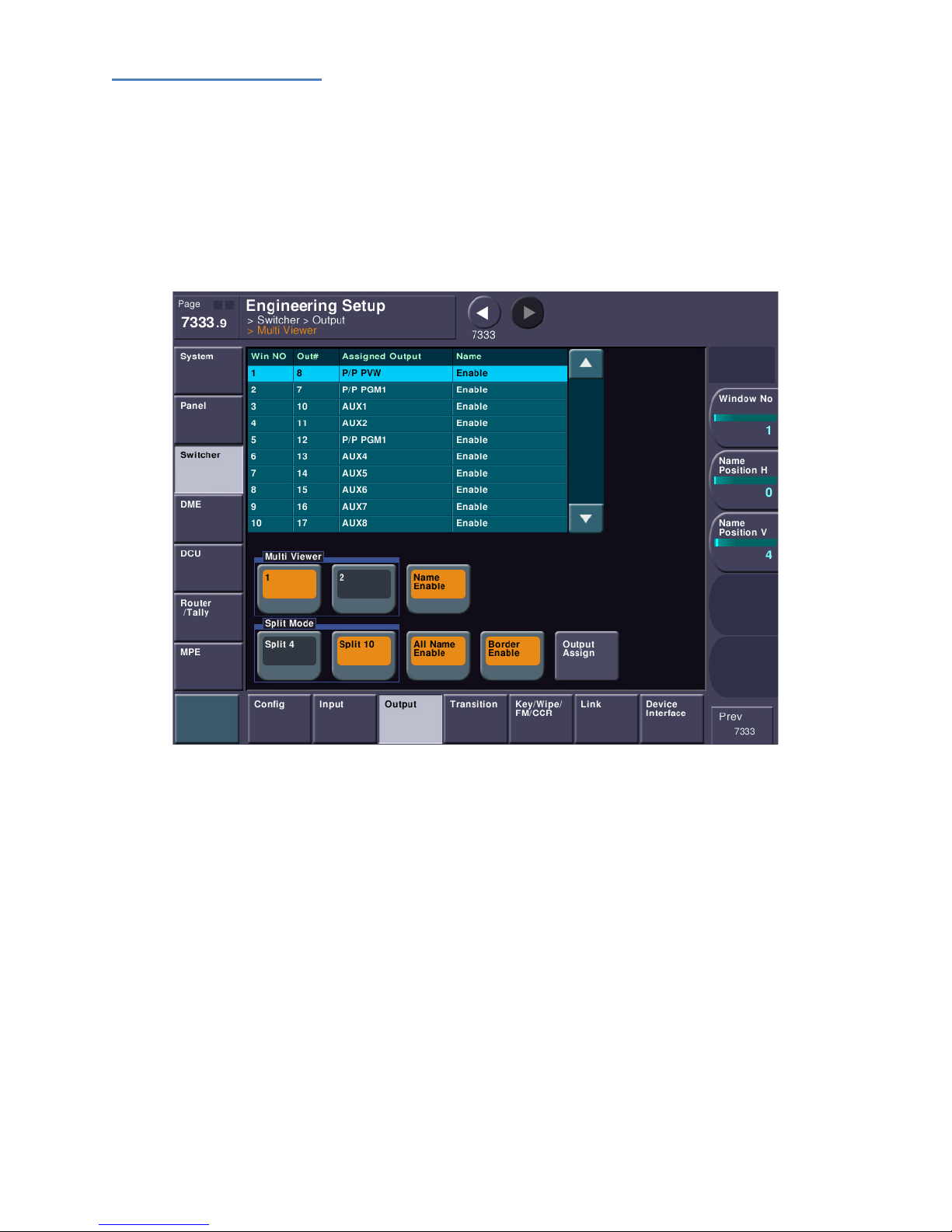
Using the Multi-Viewer
As mentioned earlier, the MVS-X series comes with either one or two multi-viewers, depending on how
many output boards were purchased. If you would like to use the multi-viewer now instead of setting
up several monitors for testing, please read on.
On the back of the switcher chassis, the multi-viewer outputs are called MSD1 and MSD2. On the
8000X, they can be found on Slot #15. On the 7000X, they are on Slot #11. The MSD2 output only
functions if you purchased 48 outputs. We’ll concentrate on the MSD1 output. Please jump to menu
page 7333.9.
This screen sets initial parameters, such as the Split Mode (4 or 10 boxes), whether output names are
superimposed on the screen and if borders are enabled between the windows. You can also use knobs
2 & 3 to adjust the position of the name titles.
Before a signal can be placed in a Multi-Viewer window, it first must be assigned to a physical output.
Also, remember that Multi-Viewer #1 can only “see” signals that come from Outputs 1-24. Multi-Viewer
#2 can only “see” signals that come from Outputs 25-48. For example, it is not possible to put Output 43
on Multi-Viewer #1. Output assignments are set on menu page 7333.1.
pg. 66
Page 67
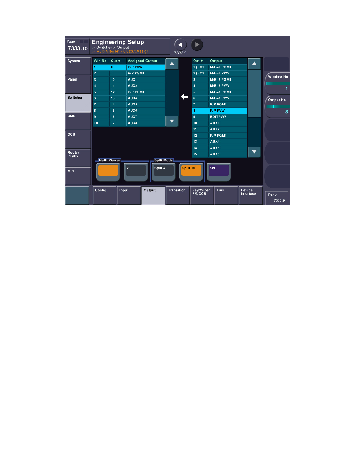
To set what is actually going to each window, please press “Output Assign.”
Here, you can select the output on the right and assign it to a specific Multi-Viewer window on the left
by pressing the SET button. Window numbers are sequential from the upper-left of the screen to the
lower-right.
pg. 67
Page 68
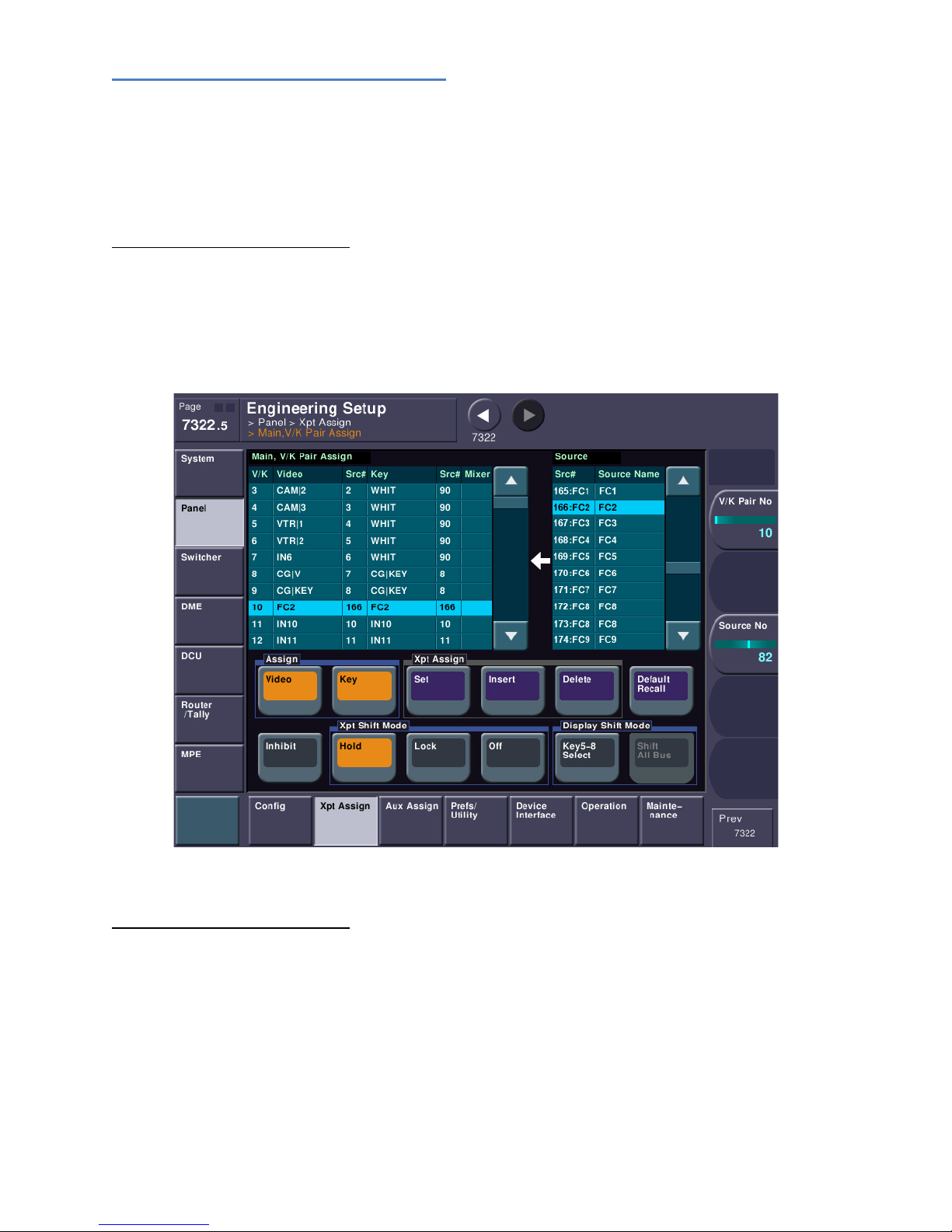
Using the internal Format Converters
If you have purchased the internal format converters for your switcher and would like to set them up,
please follow this section; otherwise please skip down to “Saving Our Work”. We have already set the
type of input(s) the FCs will be expecting earlier in this document. The input methods for MVS-7000X
and 8000X are a little different, so please refer to the correct section, below.
Format Converters for MVS-8000X
The MVS-8000X has dedicated BNC inputs for its format converters. As mentioned earlier in this
document, those inputs can be found on Slot #12. Mapping a format converter’s input to a V/K pair and
a crosspoint button are exactly the same procedures as we covered earlier. The only difference is the
source number. On the 8000X, the format converter inputs are found on source # 165-180. So, using
the same mapping procedures, make a Main V/K pair, except this time use a FC input.
Format Converters for MVS-7000X
The MVS-7000X has assignable FC mapping, rather than dedicated inputs. Please jump to menu page
7332 and select “FC Input Select”.
pg. 68
Page 69
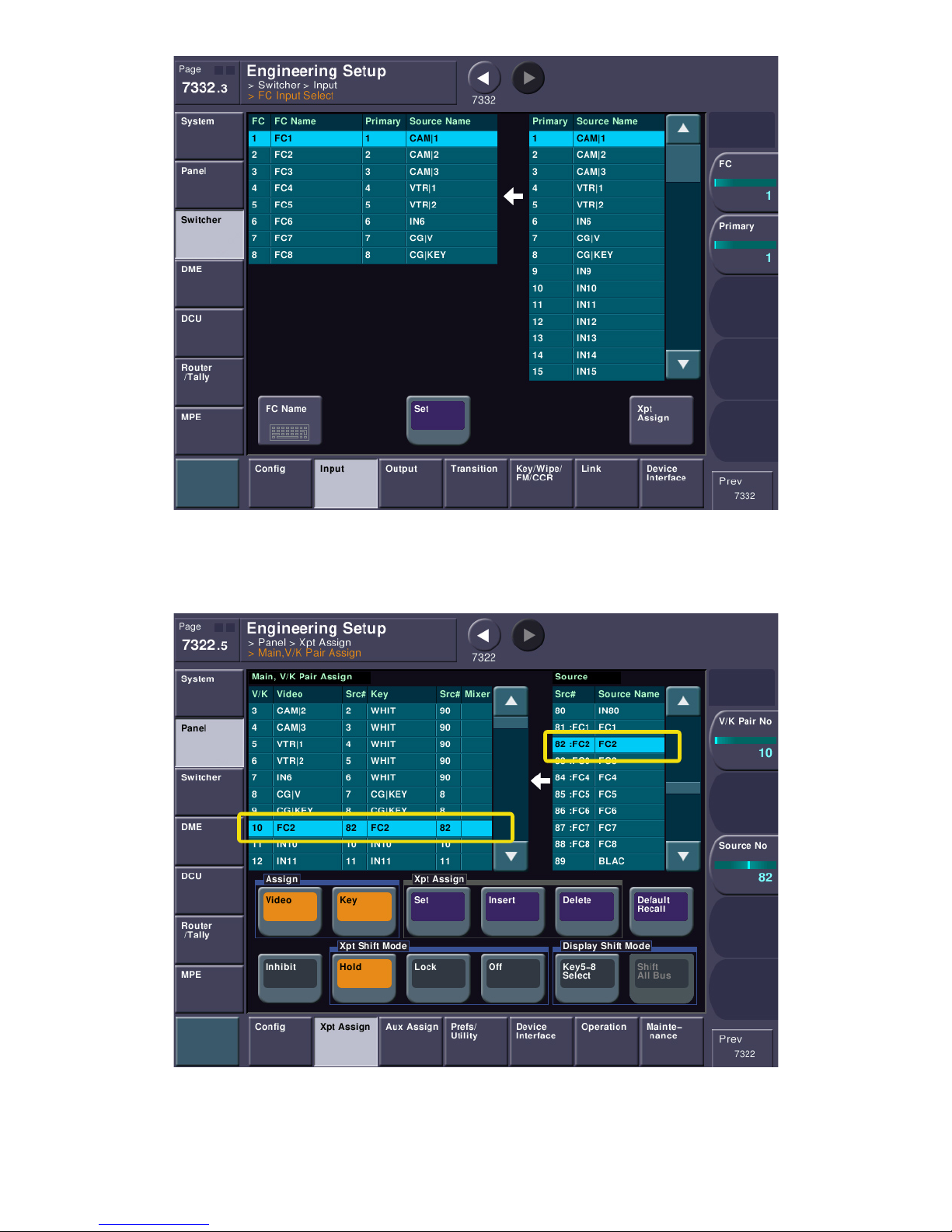
Here you can select which physical BNC input is assigned to a format converter input channel.
Then, mapping a format converter’s input to a V/K pair and a crosspoint button are exactly the same
procedures as we covered earlier.
pg. 69
Page 70
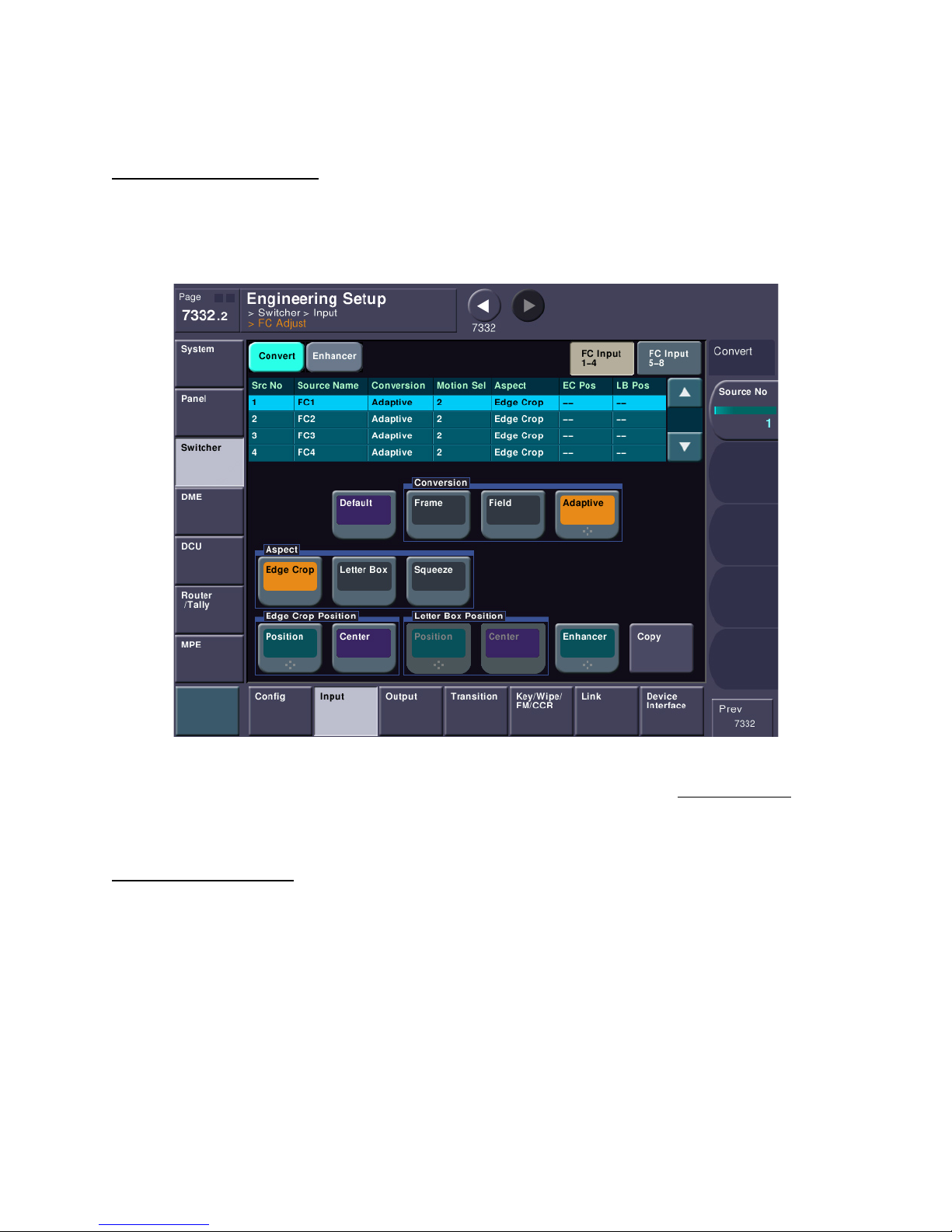
The only difference is the source number. On the 7000X, the format converter inputs are found on
source # 81-88. So, using the same mapping procedures, make a Main V/K pair, except this time use a
FC input.
Format Converter Parameters
On both the 7000X and 8000X, you can change different parameters on the format converter inputs,
such as the type of signal (is it 4:3, 16:9, letterbox) and make small tweaks such as edge enhancement.
This can be done from the “FC Adjust” button on menu page 7332.
Upconverting a CG or something with a key signal? No problem. FC inputs can be used as key signals,
too. Please keep in mind that by their very nature, converting an input will add a one frame delay to the
signal path.
Format Converter Outputs
As mentioned earlier, there are four dedicated BNC connectors for format converted outputs. If you
have 24 outputs in your switcher (and a format converter card, of course) then FC Out 1&2 will be
active. If you have 48 outputs in your switcher than all four FC outputs will be active. Each output
channel can be individually set with how the signal should be converted (edge crop, letterbox,
anamorphic 16:9, 14:9, etc). This way, if you wanted to have a “Full HD” copy, an edge crop (“center
punch”) and an anamorphic 16:9 to go to DVD, you can get all these outputs at the same time! These
adjustments are made on Menu page 7333.6. Just select the FC channel on the top table and make your
button selections.
pg. 70
Page 71
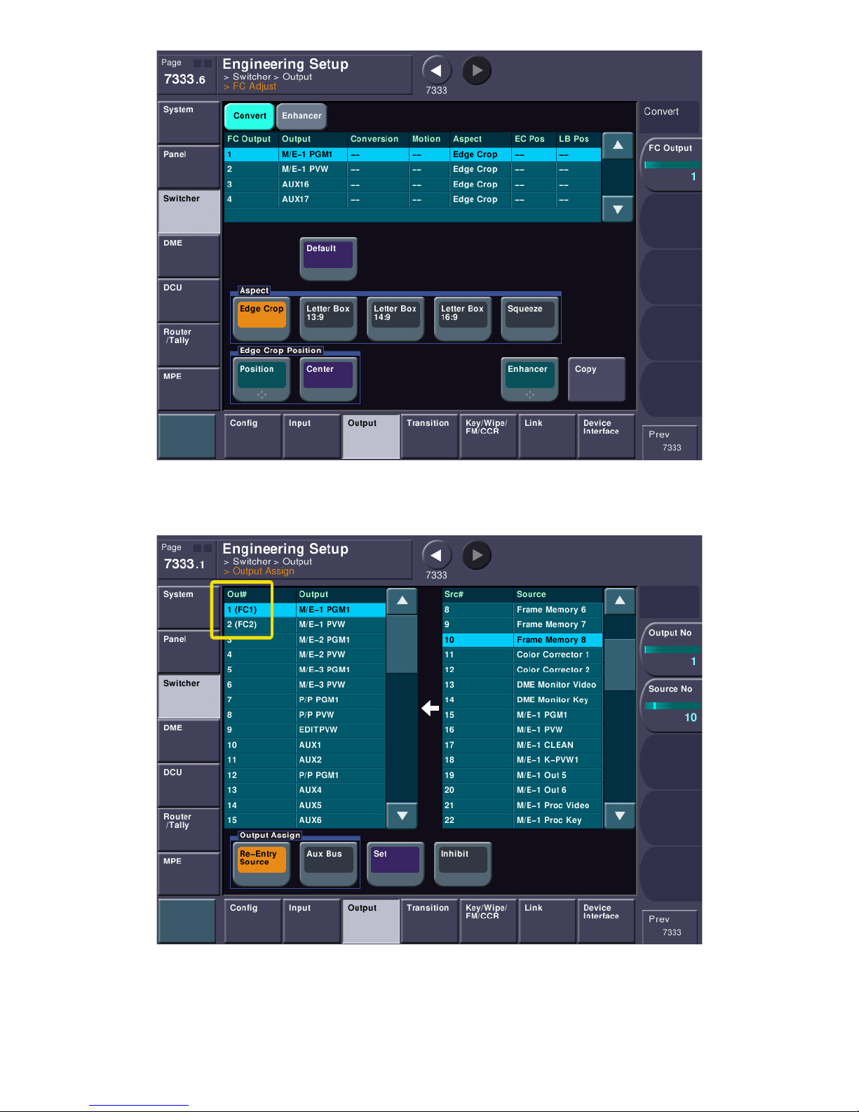
It is important to note that the routing of the signal fed to the format converter output is shared with
non-converted signals. Take a look at menu 7333.1 (switcher output assign).
You can see here that FC output #1 will be assigned the same signal as physical output #1. Format
Converter output #2 will be assigned the same signal as physical output #2. If you have 48 outputs, then
Format Converter outputs 3 and 4 share signals with physical outputs 25 & 26.
pg. 71
Page 72
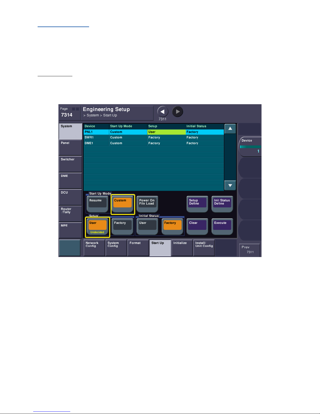
Saving Our Work
Now that we’ve gone to all this trouble to set up and program a small part of the switcher, we need to
do a couple more things. First, we need to save what we’ve done to non-volatile memory and tell the
switcher to come up this way every time.
Start-Up Mode
Please jump to menu page 7314 (ENG SETUP->SYSTEM->STARTUP). This is the menu that we will tell
the switcher how we want it to boot.
At the top list box, please select PNL1. Below, please set the Start Up Mode group to “Custom”. This
tells the switcher to boot with the selection in the “Setup” group directly below. Next, set the Setup
group to “User”. This tells the switcher to boot from the stored flash memory of settings rather than the
factory setting. If we left this in factory mode, next time you powered up the switcher, all our settings
would be lost! For now, let’s just leave the Initial Status group to Factory. This will get changed by your
operations trainer.
You need to repeat these same procedures for SWR1 (by selecting it in the top list). Set SWR1 to
Custom Start-Up mode and User Setup mode.
Next, select DME1 and do the same things as above. Finally, press the EXECTUE button to make the
system accept these changes.
pg. 72
Page 73

After you execute the changes, the top table should show the proper boot modes.
Setup Define
We have told the switcher how to boot but we actually haven’t told the switcher what to boot with. For
this we need to press SETUP DEFINE on each component.
pg. 73
Page 74
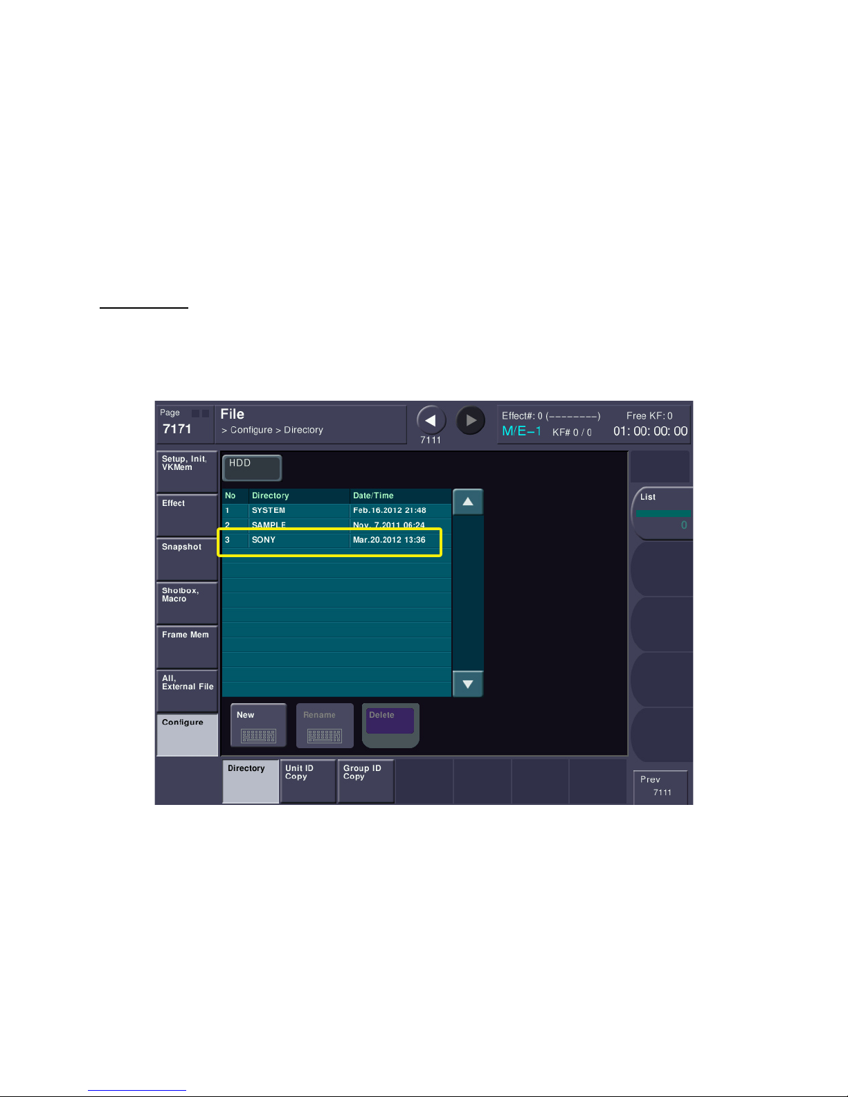
SETUP DEFINE saves most of the settings under Engineering Setup to the flash memory. So, please
select PNL1 on the top list, then press SETUP DEFINE. Repeat a SETUP DEFINE for each additional
component (SWR1, DME1 and maybe DME2).
Each of these procedures is very important to make sure your system always boots properly. The first
part (setting the startup mode) you should never have to touch again. However, when you make any
future changes to setup, you need to repeat the SETUP DEFINE procedure to re-save the flash memory
to each system component (SWR, PNL, DME). Otherwise if the switcher re-boots, it will revert to the
last save.
Saving To Disk
You might also like to save a disk file as well. Please go to menu page 7171 (FILE->Configure->Directory).
Let’s make a new folder on the internal hard drive. Press the NEW button and create a folder (8
character maximum folder name). Let’s call it “Sony”
pg. 74
Page 75
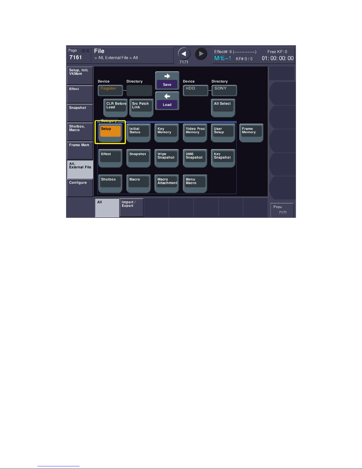
Next, jump to menu page 7161. Inside the “category” group, please make sure the only button that is
turned on is “Setup”.
This indicates that when we save the file, only setup data will be saved (no effects or any other operator
file types will be saved).
pg. 75
Page 76
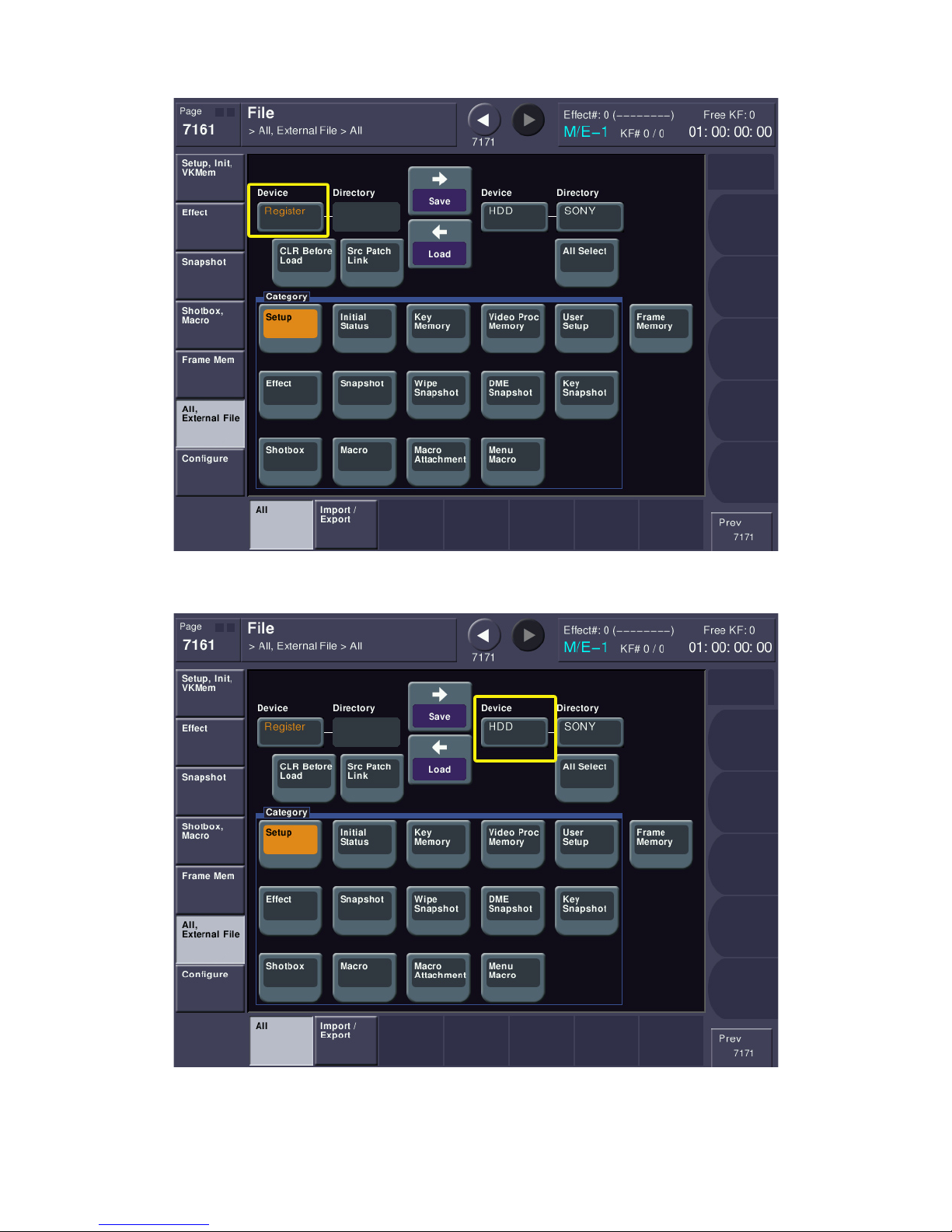
Make sure “Register” is showing on the “Device” pushbutton on the upper left.
Make sure “HDD” is showing under “Device” on the right.
pg. 76
Page 77
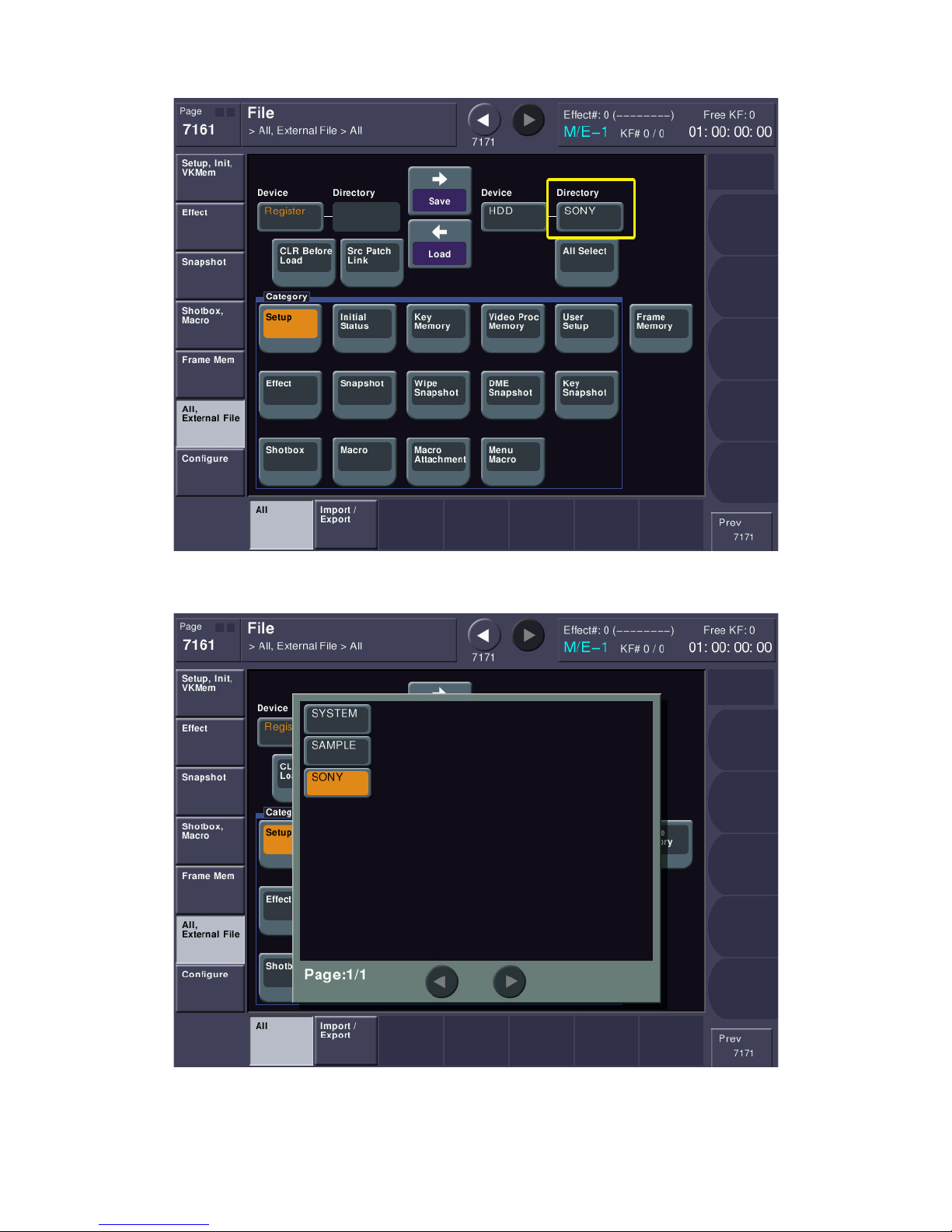
On the right, press the pushbutton under “Directory”. A popup will appear.
Select the folder name you just made (“Sony”).
pg. 77
Page 78
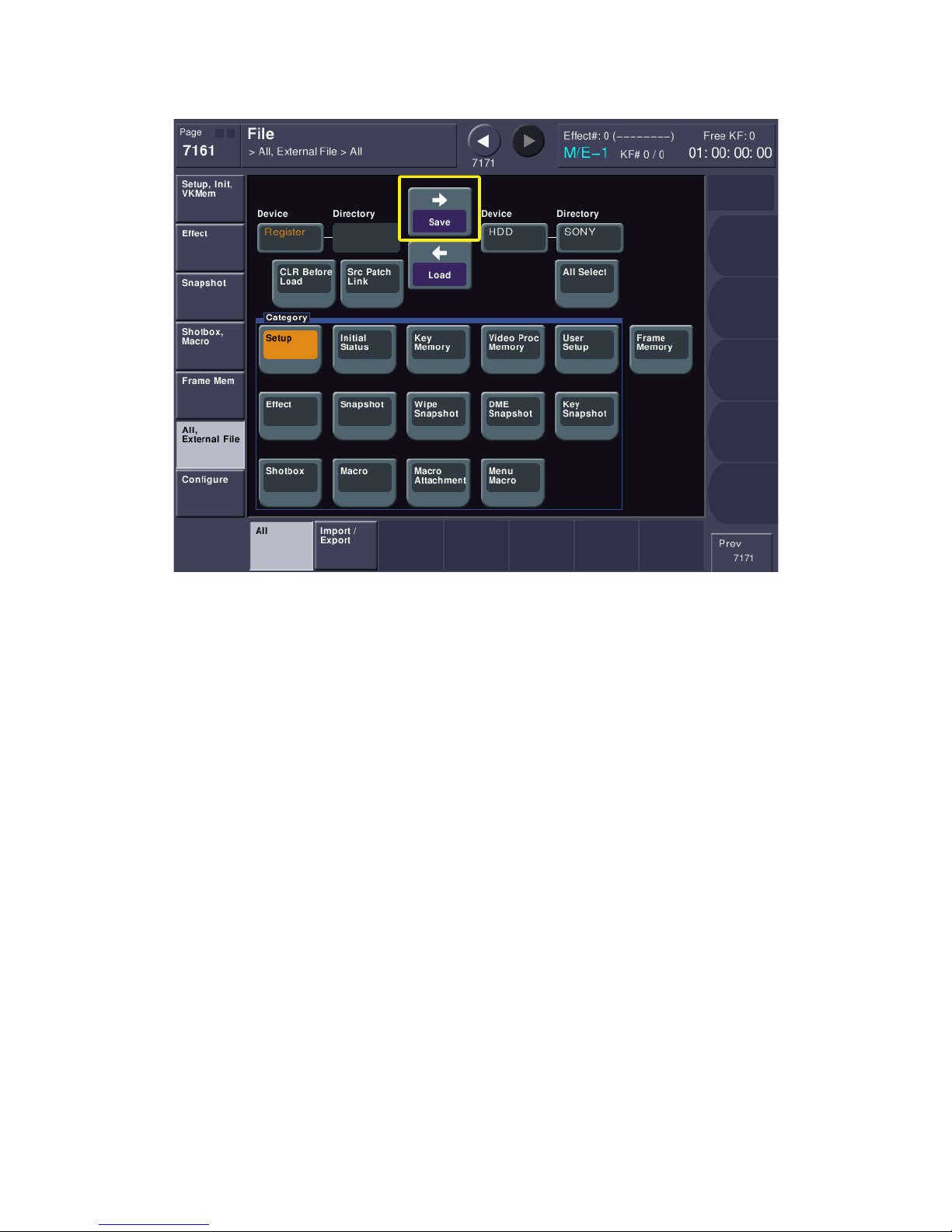
After the popup disappears, press the SAVE purple button. The right-pointing arrow over the word SAVE
indicates you will be saving data from “Register” (the switcher) to the HDD in the sub-folder.
You have now successfully saved both the flash memory of the switcher and also created an offline
version on the internal hard drive. When your Field Service Engineer arrives, they will teach you how to
also save these files on a USB drive or Memory Stick media.
pg. 78
Page 79

That’s It!
You’ve now got your new MVS switcher wired, programmed, have video running in and out and have
saved all your work!
If you haven’t already set up your Install Check-Out, please contact your Sony Account Manager. As
mentioned above, kindly give them at least 2 weeks’ notice and provide a couple of different start dates,
in case your first choice isn’t available. Please remember to give your Sony Account Manager the model
number and serial number for each chassis you purchased.
Next, it’s time to set an on-air date and prepare for operator training. As mentioned above, Sony
requires at least 30 days’ notice and it’s strongly recommended that you don’t schedule your ICO and
your operator training back-to-back, in case there’s an issue that needs resolving.
If you have any questions or just need an extra hand, please contact your Sony Account Manager. They
will find the right person to assist you.
On behalf of everyone at Sony Electronics, thank you for your purchase of the MVS “X” series production
switcher.
pg. 79
 Loading...