

Page 1

SWITCHER PROCESSOR PACK
MVS-6000-C
MULTI FORMAT SWITCHER PROCESSOR
MVS-6000
MKS-6470 MKS-8110G MKS-8161M MKS-8442G
MKS-8450G HK-PSU04 BZS-6250 BZS-6300
BZS-6420 BZS-6540M BZS-6550M
OPERATION MANUAL [English]
1st Edition
Page 2
WARNING
To reduce the risk of fire or electric shock,
do not expose this apparatus to rain or
moisture.
To avoid electrical shock, do not open the
cabinet. Refer servicing to qualified
personnel only.
communications. Operation of this equipment in a residential
area is likely to cause harmful interference in which case the
user will be required to correct the interference at his own
expense.
You are cautioned that any changes or modifications not
expressly approved in this manual could void your authority to
operate this equipment.
All interface cables used to connect peripherals must be
shielded in order to comply with the limits for a digital device
pursuant to Subpart B of Part 15 of FCC Rules.
THIS APPARATUS MUST BE EARTHED.
AVERTISSEMENT
Afin de réduire les risques d’incendie ou
d’électrocution, ne pas exposer cet
appareil à la pluie ou à l’humidité.
Afin d’écarter tout risque d’électrocution,
garder le coffret fermé. Ne confier
l’entretien de l’appareil qu’à un personnel
qualifié.
CET APPAREIL DOIT ÊTRE RELIÉ À LA
TERRE.
WARNUNG
Um die Gefahr von Bränden oder
elektrischen Schlägen zu verringern, darf
dieses Gerät nicht Regen oder Feuchtigkeit
ausgesetzt werden.
Um einen elektrischen Schlag zu
vermeiden, darf das Gehäuse nicht
geöffnet werden. Überlassen Sie
Wartungsarbeiten stets nur qualifiziertem
Fachpersonal.
DIESES GERÄT MUSS GEERDET
WERDEN.
For the customers in the U.S.A.
This equipment has been tested and found to comply with the
limits for a Class A digital device, pursuant to Part 15 of the
FCC Rules. These limits are designed to provide reasonable
protection against harmful interference when the equipment is
operated in a commercial environment. This equipment
generates, uses, and can radiate radio frequency energy and,
if not installed and used in accordance with the instruction
manual, may cause harmful interference to radio
This device complies with Part 15 of the FCC Rules. Operation
is subject to the following two conditions: (1) this device may
not cause harmful interference, and (2) this device must
accept any interference received, including interference that
may cause undesired operation.
For the customers in Canada
This Class A digital apparatus complies with Canadian
ICES-003.
Pour les clients au Canada
Cet appareil numérique de la classe A est conforme à la
norme NMB-003 du Canada.
This symbol is intended to alert the user to the
presence of important operating and
maintenance (servicing) instructions in the
literature accompanying the appliance.
WARNING: THIS WARNING IS APPLICABLE FOR USA
ONLY.
If used in USA, use the UL LISTED power cord specified
below.
DO NOT USE ANY OTHER POWER CORD.
Plug Cap Parallel blade with ground pin
(NEMA 5-15P Configuration)
Cord Type SJT, three 16 or 18 AWG wires
Length Minimum 1.5m (4 ft .11in.), Less than 2.5 m (8 ft .3 in.)
Rating Minimum 10A, 125V
Using this unit at a voltage other than 120V may require the
use of a different line cord or attachment plug, or both. To
reduce the risk of fire or electric shock, refer servicing to
qualified service personnel.
WARNING: THIS WARNING IS APPLICABLE FOR OTHER
COUNTRIES.
1. Use the approved Power Cord (3-core mains lead) /
Appliance Connector / Plug with earthing-contacts that
conforms to the safety regulations of each country if
applicable.
2. Use the Power Cord (3-core mains lead) / Appliance
Connector / Plug conforming to the proper ratings (Voltage,
Ampere).
2
Page 3

If you have questions on the use of the above Power Cord /
Appliance Connector / Plug, please consult a qualified service
personnel.
AVERTISSEMENT
1.Utilisez un cordon d’alimentation (câble secteur à 3 fils)/
fiche femelle/fiche mâle avec des contacts de mise à la terre
conformes à la réglementation de sécurité locale applicable.
2.Utilisez un cordon d’alimentation (câble secteur à 3 fils)/
fiche femelle/fiche mâle avec des caractéristiques
nominales (tension, ampérage) appropriées.
Pour toute question sur l’utilisation du cordon d’alimentation/
fiche femelle/fiche mâle ci-dessus, consultez un technicien du
service après-vente qualifié.
WARNUNG
1.Verwenden Sie ein geprüftes Netzkabel (3-adriges
Stromkabel)/einen geprüften Geräteanschluss/einen
geprüften Stecker mit Schutzkontakten entsprechend den
Sicherheitsvorschriften, die im betreffenden Land gelten.
2.Verwenden Sie ein Netzkabel (3-adriges Stromkabel)/einen
Geräteanschluss/einen Stecker mit den geeigneten
Anschlusswerten (Volt, Ampere).
Wenn Sie Fragen zur Verwendung von Netzkabel/
Geräteanschluss/Stecker haben, wenden Sie sich bitte an
qualifiziertes Kundendienstpersonal.
For the customers in Europe (MVS-6000 only)
This product with the CE marking complies with both the EMC
Directive and the Low Voltage Directive issued by the
Commission of the European Community.
Compliance with these directives implies conformity to the
following European standards:
• EN60950-1: Product Safety
• EN55103-1: Electromagnetic Interference (Emission)
• EN55103-2: Electromagnetic Susceptibility (Immunity)
This product is intended for use in the following
Electromagnetic Environment: E4 (controlled EMC
environment, ex. TV studio).
Pour les clients en Europe (MVS-6000 uniquement)
Ce produit portant la marque CE est conforme à la fois à la
Directive sur la compatibilité électromagnétique (EMC) et à la
Directive sur les basses tensions émises par la Commission
de la Communauté Européenne.
La conformité à ces directives implique la conformité aux
normes européennes suivantes:
• EN60950-1 : Sécurité des produits
• EN55103-1 : Interférences électromagnétiques (émission)
• EN55103-2 : Sensibilité électromagnétique (immunité)
Ce produit est prévu pour être utilisé dans l’environnement
électromagnétique suivants: E4 (environnement EMC
contrôlé, ex. studio de télévision).
Angewandte Normen:
• EN60950-1: Sicherheitsbestimmungen
• EN55103-1: Elektromagnetische Verträglichkeit
(Störaussendung)
• EN55103-2: Elektromagnetische Verträglichkeit
(Störfestigkeit)
Für die folgenden elektromagnetischen Umgebungen: E4
(kontrollierter EMV-Bereich, z.B. Fernsehstudio).
For the customers in Europe (optional boards and
HK-PSU04 only)
This product with the CE marking complies with the EMC
Directive issued by the Commission of the European
Community.
Compliance with this directive implies conformity to the
following European standards:
• EN55103-1: Electromagnetic Interference (Emission)
• EN55103-2: Electromagnetic Susceptibility (Immunity)
This product is intended for use in the following
Electromagnetic Environment: E4 (controlled EMC
environment, ex. TV studio).
Pour les clients en Europe (cartes optionnelles et
HK-PSU04 uniquement)
Ce produit portant la marque CE est conforme à la Directive
sur la compatibilité électromagnétique (EMC) émise par la
Commission de la Communauté européenne.
La conformité à cette directive implique la conformité aux
normes européennes suivantes:
• EN55103-1 : Interférences électromagnétiques (émission)
• EN55103-2 : Sensibilité électromagnétique (immunité)
Ce produit est prévu pour être utilisé dans l’environnement
électromagnétique suivant: E4 (environnement EMC contrôlé,
ex. studio de télévision).
Für Kunden in Europa (nur optionale Zusatzkarten und
HK-PSU04)
Dieses Produkt besitzt die CE-Kennzeichnung und erfüllt die
EMV-Richtlinie der EG-Kommission.
Angewandte Normen:
• EN55103-1: Elektromagnetische Verträglichkeit
(Störaussendung)
• EN55103-2: Elektromagnetische Verträglichkeit
(Störfestigkeit)
Für die folgende elektromagnetische Umgebung: E4
(kontrollierter EMV-Bereich, z.B. Fernsehstudio).
For the customers in Europe
The manufacturer of this product is Sony Corporation, 1-7-1
Konan, Minato-ku, Tokyo, Japan.
The Authorized Representative for EMC and product safety is
Sony Deutschland GmbH, Hedelfinger Strasse 61, 70327
Stuttgart, Germany. For any service or guarantee matters
please refer to the addresses given in separate service or
guarantee documents.
Für Kunden in Europa (nur MVS-6000)
Dieses Produkt besitzt die CE-Kennzeichnung und erfüllt die
EMV-Richtlinie sowie die Niederspannungsrichtlinie der EGKommission.
This apparatus shall not be used in the residential area.
3
Page 4

Pour les clients en Europe
Le fabricant de ce produit est Sony Corporation, 1-7-1 Konan,
Minato-ku, Tokyo, Japon.
Le représentant autorisé pour EMC et la sécurité des produits
est Sony Deutschland GmbH, Hedelfinger Strasse 61, 70327
Stuttgart, Allemagne. Pour toute question concernant le
service ou la garantie, veuillez consulter les adresses
indiquées dans les documents de service ou de garantie
séparés.
Ne pas utiliser cet appareil dans une zone résidentielle.
Für Kunden in Europa
Der Hersteller dieses Produkts ist Sony Corporation, 1-7-1
Konan, Minato-ku, Tokyo, Japan.
Der autorisierte Repräsentant für EMV und Produktsicherheit
ist Sony Deutschland GmbH, Hedelfinger Strasse 61, 70327
Stuttgart, Deutschland. Bei jeglichen Angelegenheiten in
Bezug auf Kundendienst oder Garantie wenden Sie sich bitte
an die in den separaten Kundendienst- oder
Garantiedokumenten aufgeführten Anschriften.
Dieser Apparat darf nicht im Wohnbereich verwendet werden.
For the customers in Europe, Australia and New Zealand
WARNING
This is a Class A product. In a domestic environment, this
product may cause radio interference in which case the user
may be required to take adequate measures.
Pour les clients en Europe, Australie et Nouvelle-Zélande
AVERTISSEMENT
Il s’agit d’un produit de Classe A. Dans un environnement
domestique, cet appareil peut provoquer des interférences
radio, dans ce cas l’utilisateur peut être amené à prendre des
mesures appropriées.
Für Kunden in Europa, Australien und Neuseeland
WARNUNG
Dies ist eine Einrichtung, welche die Funk-Entstörung nach
Klasse A besitzt. Diese Einrichtung kann im Wohnbereich
Funkstörungen verursachen; in diesem Fall kann vom
Betreiber verlangt werden, angemessene Maßnahmen
durchzuführen und dafür aufzukommen.
4
Page 5

Table of Contents
Overview ............................................................................... 6
Features ..................................................................................... 6
Overview of the MVS-6000 Series Components...................... 7
Location and Function of Parts .......................................... 8
Front Panel ................................................................................8
Rear Panel..................................................................................9
Example System Configuration ........................................ 11
MVS-6000 System Configuration...........................................11
Flow of Video Signals.............................................................12
Power Supply Unit Status Indicators ............................... 13
Specifications..................................................................... 13
MVS-6000 Multi Format Switcher Processor......................... 13
MKS-6470 DME Board Set .................................................... 14
MKS-8110G 17-Input Board................................................... 14
MKS-8161M Monitor Output Board ...................................... 15
MKS-8442G Frame Memory Board ....................................... 15
MKS-8450G Format Converter Board.................................... 15
HK-PSU04 Power Supply Unit............................................... 15
Table of Contents
5
Page 6

Overview
The MVS-6000-C Switcher Processor Pack is a highperformance, multi-function processor for use in an
MVS-6000 Multi Format Switcher system. It has a wide
range of application, being usable in live production
systems in studios and ENG/OB vans as well as in
postproduction editing systems.
Features
Multi format support
The MVS-6000 system is available in two configurations:
a multi-format SD/HD configuration and an SD-only
configuration. The SD-only configuration can be upgraded
to the multi-format configuration.
• SD/HD multi format configuration
1080i/59.94, 1080i/50, 720P/59.94, 720P/50, 480i/
59.94, 576i/50
• SD-only configuration
480i/59.94, 576i/50
Key resizer functions
• Magnify, shrink, move, change aspect ratio
• Two resizer channels are provided per M/E bank.
• Snapshots and keyframes
• Crop, Border
• Mosaic, Defocus
Format converter functions
• Input side format converter
Up-converter, down-converter, cross-converter
Eight channels
• Output side format converter
Up-converter, down-converter, cross-converter
Maximum two channels (requires at least one optional
MKS-8450G board)
Highly expandable system configuration
By combining option boards, you can configure the
optimum system for your requirements, selecting the
number of inputs and outputs, and the number of M/E
banks. The system’s flexibility guarantees its ability to
meet future expansion requirements.
• Chroma key and color vector keys in each keyer
• FineKey
• Color mixable matte generator available for both key fill
and key borders
TM
, and key borders up to 8H
Simultaneous output of two programs
Each M/E bank is able to handle two simultaneous
program outputs, with the ability to apply any of the four
keys to program output. This gives the system the ability
to handle a wide range of operating situations, for example
simultaneous transmission of two programs.
Powerful preview functions
The system supports simultaneous output of look-ahead
previews (next preview) and key previews, and also
transition previews.
Extended frame memory functions
• Two-input, eight-output frame memory
• Maintains all MVS-8000G/8000GSF frame memory
functions: freeze function, mask function, reposition
function, and image composition function
• Approximately 5.4 GB large capacity memory
• Includes animation function
• Interface connection for external hard disk drive
provided
Two channels of DME available
By installing an optional DME board, you can apply DME
wipes and processed keys and a wide variety of other DME
functions as if they were native switcher functions. All
DME functions can be controlled from the center control
panel of the MVS-6000 system.
Backup power supply can be installed
By installing the optional HK-PSU04 Power Supply Unit,
together with the power supply unit preinstalled at the
factory, this provides a backup system. This reduces the
risk of power supply problems, and increases the reliability
of live operations.
High-performance color correction
Installation of the optional MKS-8442G Frame Memory
Board and BZS-6420 Color Corrector Software provides
high-performance, two-channel color correction
functionality.
High-performance keyers
Each M/E bank is equipped with four high-performance
keyers that provide the following standard functions.
• Ability to apply transitions to keyers independently of
the background
6
Overview
Simple P/P (Program/Preset) functions
Simple mix/effect functions can be added by installing the
BZS-6250 Simple P/P Software option.
The BZS-6250 option supports the following functions.
•Two keyers
Page 7
• Background transitions and key transitions
• Background DME wipe
Overview of the MVS-6000 Series Components
MVS-6000 Multi Format Switcher
Processor
This is the main unit cabinet of the MVS-6000 multi
format switcher processor unit (EIA 4RU size).
By default the main unit alone supports SD only, but it can
be upgraded to multi-format HD/SD by installing an
optional software upgrade.
• An M/E bank installed as standard; can be extended to
two M/E banks.
• 15 inputs installed as standard; can be extended to 49
inputs.
• 24 inputs installed as standard.
• Color corrector software (option) can be installed.
• A frame memory option board can be installed.
• Up to one format converter board (option) can be
installed. 8 inputs and 2 outputs.
• A power supply unit fitted as standard.
MKS-8442G Frame Memory Board
This is a frame memory board. One board can be installed
in the MVS-6000.
MKS-8450G Format Converter Board
This is a format converter board. One board can be
installed in the MVS-6000.
HK-PSU04 Power Supply Unit
This is a backup power supply unit. The MVS-6000 is
equipped with a power supply unit preinstalled at the
factory, and installing another unit provides a fully
redundant power supply.
BZS-6250 Simple P/P Software
This is software which enables simple Program/Preset
functions on the MVS-6000.
BZS-6300 Additional M/E Software
This is software to enable the standard MVS-6000 with
one M/E bank to be used as a two M/E system.
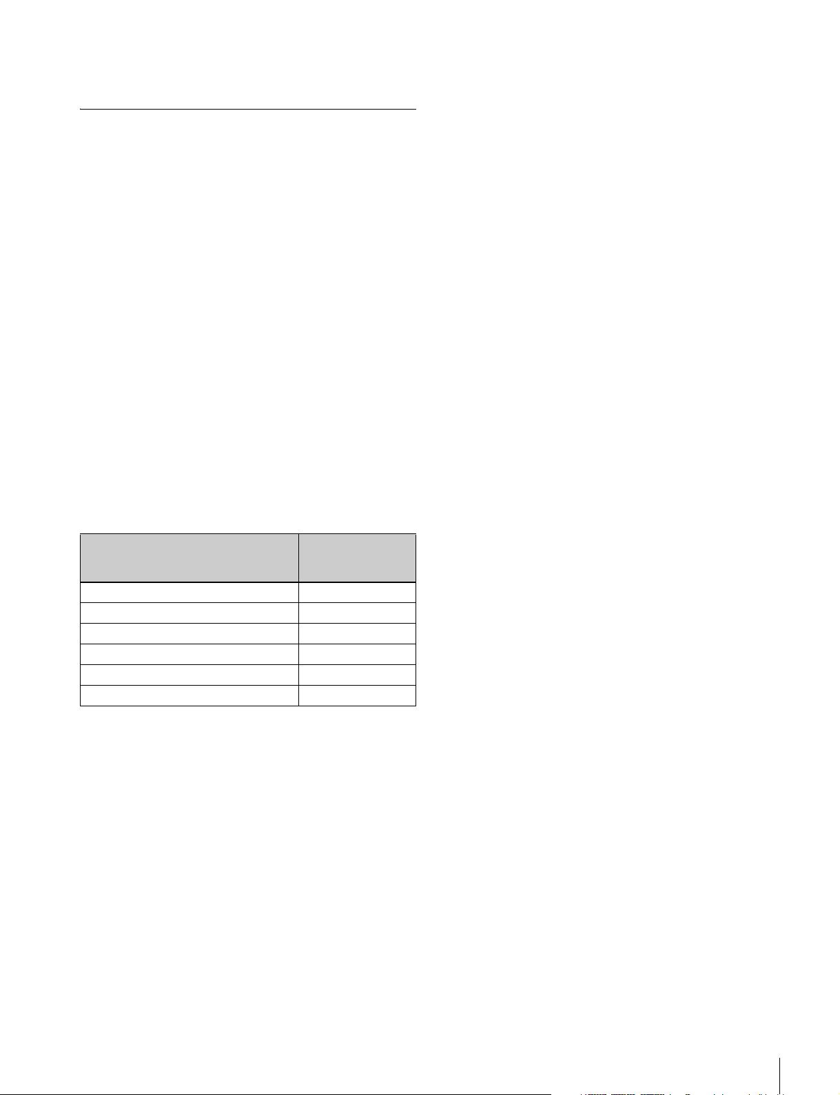
The following options can be installed, depending on the
system.
Board Name Maximum
installable number
of boards
MKS-6470 DME Board Set 1
MKS-8110G 17-Input Board 2
MKS-8161M Monitor Output Board 1
MKS-8442G Frame Memory Board 1
MKS-8450G Format Converter Board 1
HK-PSU04 Power Supple Unit 1
MKS-6470 DME Board Set
This is an option board set to provide two-channel DME
functions. In the MVS-6000, one set can be installed.
MKS-8110G 17-Input Board
This is a 17-input board. The MVS-6000 has 15 inputs
fitted as standard, and by installing 17 inputs at a time with
this board, a maximum of 49 inputs (with two boards
added) can be reached.
BZS-6420 Color Corrector Software
This is software which enables high-performance color
correction of two channels. It supports both HD and SD.
The optional MKS-8442G Frame Memory Board must be
installed to use this software.
BZS-6540M Switcher Upgrade Software
This is software to upgrade a standard MVS-6000 (for SD;
with one M/E bank) to support multi-format switching.
BZS-6550M Switcher Upgrade Software
This is software to enable an M/E bank of the MVS-6000
(for SD; with one M/E bank) enabled by BZS-6300 to
support multi-format switching.
MKS-8161M Monitor Output Board
This is an HD/SD eight-output board for monitoring input
signals. (This output board only carries out reclocking of
the input signal, and no other processing.) One board can
be installed in the MVS-6000.
Overview
7
Page 8
Location and Function of Parts
Front Panel
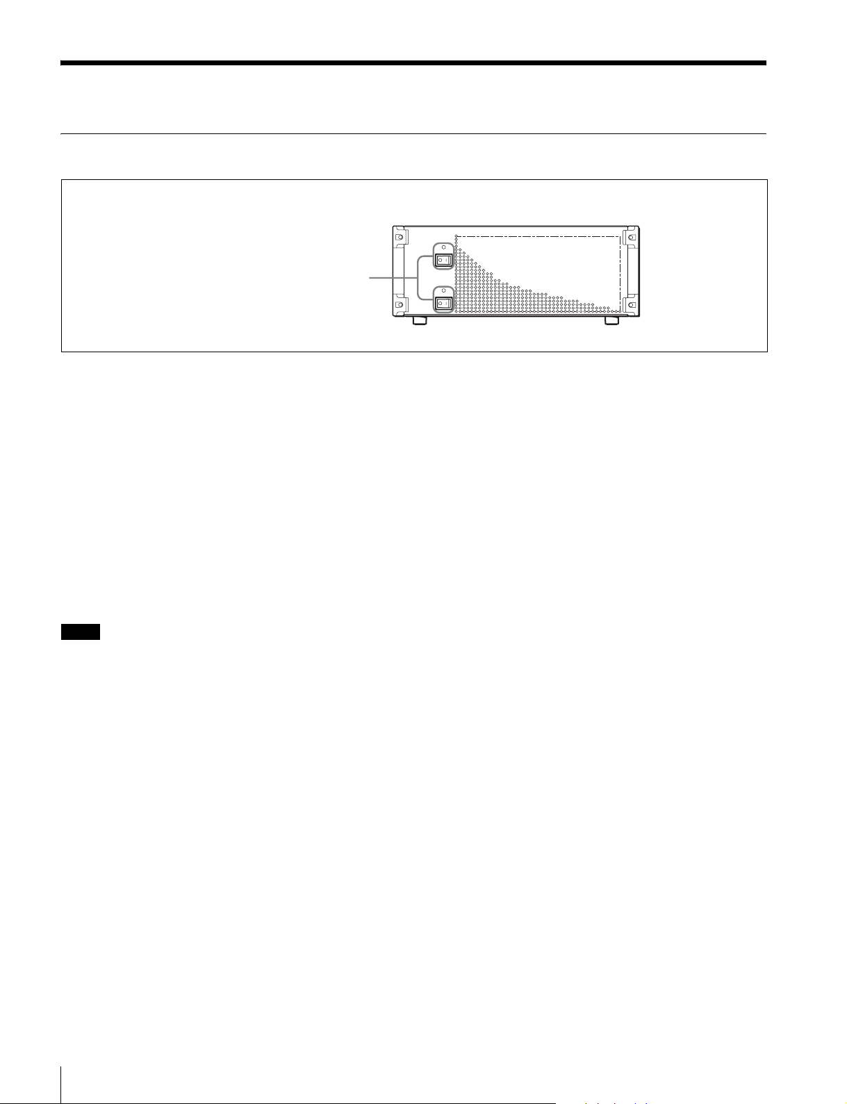
POWER A, B switches and status indicators
POWER A, B switches and status indicators
The POWER switches turn the unit on and off. The unit is
powered on when the POWER switches are on the “ ? ”
side, and powered off when the POWER switches are on
the “a” side. The status indicators light in green when the
unit is powered on.
Depending on the configuration of your unit when
shipped, the HK-PSU04 Power Supply Unit may not be
installed. In this case, only the POWER A switch is
available. There is no POWER B switch. The unit does not
operate until either of the two power switches (A and B) is
on.
When the HK-PSU04 is installed, operation continues as
long as one power supply is normal.
Notes
• When installing the HK-PSU04 in your unit, be sure to
contact your Sony service representative.
• If a status indicator does not light when you turn a
POWER switch on, there may be a fault in the power
circuits. Turn the POWER switch off and contact your
Sony service representative.
8
Location and Function of Parts
Page 9
Rear Panel
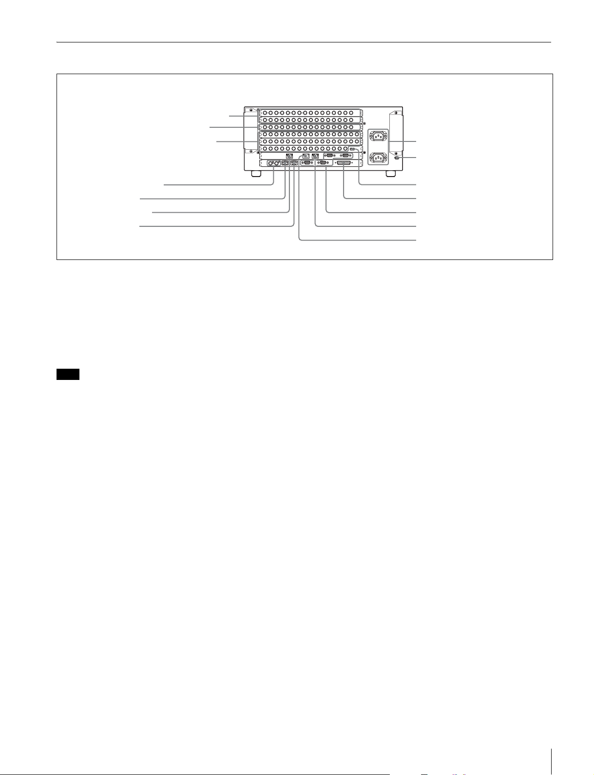
qfOUTPUTS 1 to 24 and FC 1, 2 connectors
qdMONITOR OUT 25 to 32 connectors
qsPRIMARY INPUTS 1 to 49 connectors
1-AC IN A and B connectors
2U terminal
qaREF INPUT connectors
0DATA connector
9FM DATA connector
8CTRL connector
a - AC IN (AC power input) A and B connectors
(3-pin)
Connect to 100 to 240 V AC power supply with the
optional AC power cords.
Depending on the configuration of your unit when
shipped, the HK-PSU04 Power Supply Unit may not be
installed. In that case, the AC IN B connector is not used.
Note
For information about installing an HK-PSU04 Power
Supply Unit, contact your Sony service representative.
b U (signal ground) terminal
Connect to the system ground.
c FM (frame memory) DEVICE connector
(IEEE1394 compliant)
This connector is for attaching an external hard disk drive
for frame memory.
3FM DEVICE connector
4GPI connector
5REMOTE 1 to 4 connectors
6DME CTRL connector
7DME DATA connector
Define the types of the connected devices on the center
control panel.
f DME CTRL (Digital multi effect control)
connector (RJ-45 compliant) (MKS-6470)
Connect to an Ethernet
* switch.
The MVS-6000 system’s center control panel is connected
in the same way to the Ethernet switch to form a network
for exchange of signals between the devices.
This network is used primarily to control the various
devices from the center control panel of the MVS-6000
system.
g DME DATA (Digital multi effect data) connector
(RJ-45 compliant) (MKS-6470)
Connect to an Ethernet
* switch.
The MVS-6000 system’s center control panel is connected
in the same way to the Ethernet switch to form a network
for exchange of signals between the devices.
For details of hard disk drives that can be used with the
MVS-6000 system, consult your Sony service
representative.
d GPI (General Purpose Interface) connector (D-sub
25-pin)
Connect to external devices for input and output of trigger
signals. Up to eight inputs and eight outputs are possible,
with input and output conditions set on the center control
panel.
e REMOTE 1 to 4 connectors (D-sub 9-pin, RS-422A
compliant)
These connectors are used to control the auxiliary bus of
the MVS-6000 series from external devices, or to operate
the MVS-6000 from editing control systems such as the
BVE-9100.
h CTRL (control) connector (RJ-45 compliant)
Connect to an Ethernet
*
switch.
The MVS-6000 system’s center control panel is connected
in the same way to the Ethernet switch to form a network
for exchange of signals between the devices.
This network is used primarily to control the various
devices from the center control panel of the MVS-6000
system.
i FM DATA (frame memory data) connector (RJ-45
compliant)
Connect to an Ethernet* switch. This is a dedicated LAN
connector for image data.
j DATA connector (RJ-45 compliant)
Connect to an Ethernet* switch.
Location and Function of Parts
9
Page 10
The MVS-6000 system’s center control panel is connected
in the same way to the Ethernet switch to form a network
for exchange of signals between the devices.
This network is used primarily for exchange of various
types of data (key frame effects, snapshots, etc.) and still
pictures of frame memory.
CAUTION
• When you connect the FM DATA connector, DATA
connector, CTRL connector, DME CTRL connector,
and DME DATA connector of the unit to peripheral
devices, use a shielded-type cable to prevent
malfunction due to radiation noise.
• For safety, do not connect the connector for peripheral
device wiring that might have excessive voltage to the
following port(s).
- FM DATA (frame memory data) connector
- CTRL (control) connector
- DATA connector
- DME CTRL (digital multi effect control) connector
- DME DATA (digital multi effect data) connector
Follow the instructions for the above port(s).
* For information about Ethernet switches that can be used in an MVS-6000
system, contact your Sony service representative.
ATTENTION
Par mesure de sécurité, ne raccordez pas le connecteur
pour le câblage de périphériques pouvant avoir une tension
excessive aux ports suivants.
- FM DATA connecteur
- CTRL connecteur
- DATA connecteur
- DME CTRL connecteur
- DME DATA connecteur
Suivez les instructions pour les ports ci-dessus.
VORSICHT
Aus Sicherheitsgründen nicht mit einem PeripheriegerätAnschluss verbinden, der zu starke Spannung für diese
Buchse haben könnte.
- Buchse FM DATA
- Buchse CTRL
- Buchse DATA
- Buchse DME CTRL
- Buchse DME DATA
Folgen Sie den Anweisungen für die oben aufgeführten
Buchsen.
k REF INPUT (reference video input) connectors
(BNC-type)
If you wish to synchronize this unit to an external reference
signal, input the reference signal. For an HDTV system,
input an HD tri-level sync signal, black burst signal, or
analog sync signal. For an SDTV system, input a black
burst signal or analog sync signal.
The two connectors have a loop-through configuration.
Signal input to one connector can be output from the other
connector. If you will not be using the loop-through
output, be sure to terminate the unused connector with the
supplied 75Ω terminator.
l PRIMARY INPUTS 1 to 49 connectors (BNC-type)
These connectors can be used to input up to 49 serial
digital video signals.
The number of these connectors (slots) depends on the
number of MKS-8110G boards that are installed in the
unit.
These connectors allow you to connect with an
MVE-8000A Multi Format DME Processor.
m MONITOR OUT connectors 25 to 32 (BNC-type)
(MKS-8161M)
These are used for auxiliary output to a primary input
monitor or external device. These outputs are useful for
outputting a primary input signal with as little delay as
possible.
n OUTPUTS 1 to 24 connectors (BNC-type)
These connectors output serial digital signals. You can
assign them freely as program output, preview output,
AUX output, and so on.
Outputs 1, 2, 13 to 16 are each constituted by two BNCtype connectors, and outputs 3 to 12, 17 to 24 are each
constituted by one BNC-type connector.
Make output assignments on the MVS-6000 system center
control panel.
Refer to the User’s Guide for information about signals
that may be assigned.
FC1 and 2 (slot 2) connectors (BNC-type): MVS-6000
(MKS-8450G)
The connectors output signals converted with the format
converter function.
Assign the outputs on the center control panel of the MVS6000 system.
For more information about Ethernet switch connectors,
see “MVS-6000 System Configuration” (page 11).
For detailed information about setting up the Ethernet
switch, refer to the documentation supplied with the
switch.
10
Location and Function of Parts
Page 11
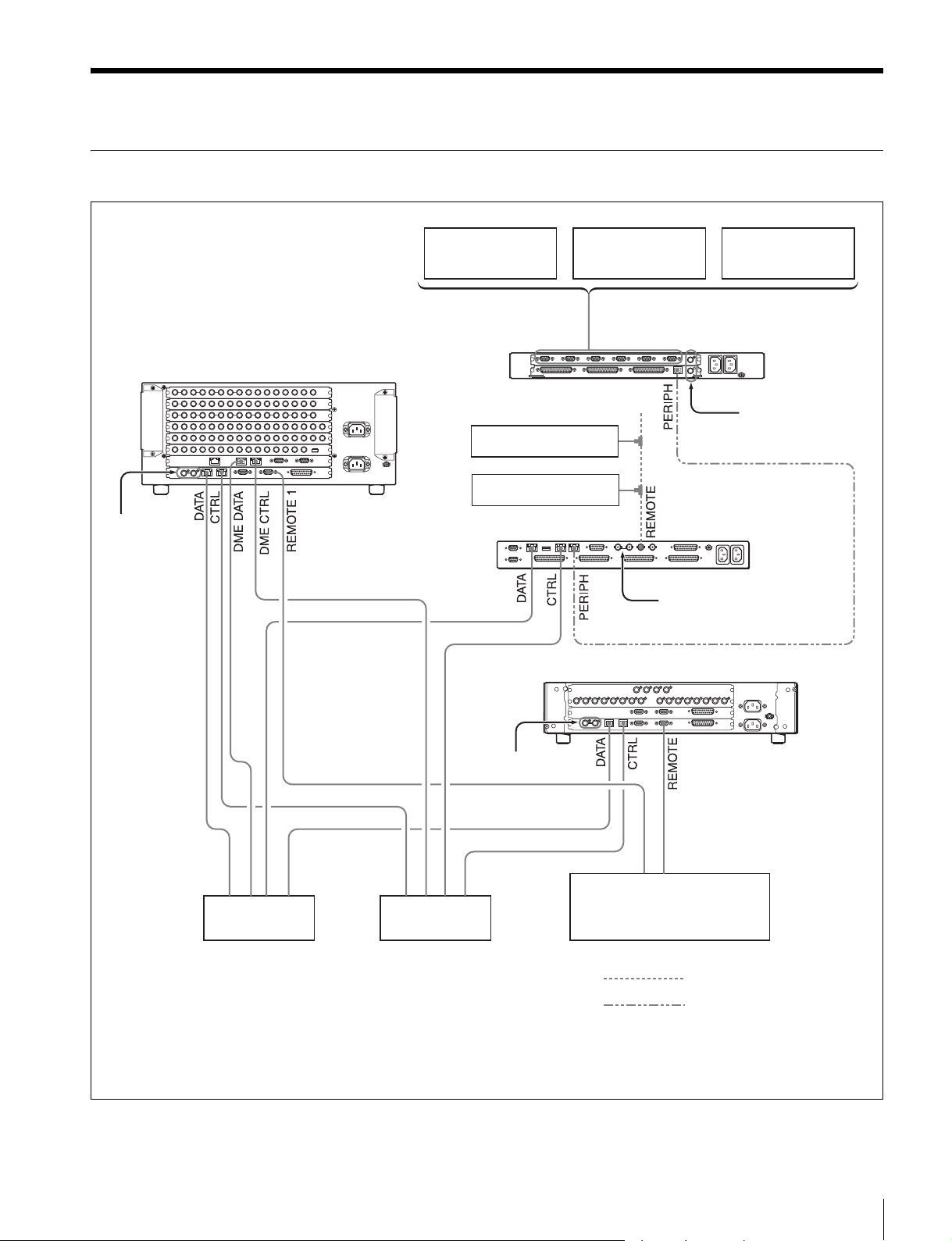
Example System Configuration
MVS-6000 System Configuration
MVS-6000 Multi Format
Switcher Processor
Reference
video signal
b)
VTR
BKS-R Series
IXS Series
DDR
MKS-2700 Device
Control Unit
MKS-8010B System
Control Unit
Reference video signal
Audio Mixer
Reference
video signal
b)
b)
Reference video signal
Ethernet switch
a) It is recommended that the CTRL and DATA LAN networks be
configured by connecting separate Ethernet switches for each
LAN.
a)
Ethernet switch
b)
a)
b) Terminate with the supplied 75Ω terminators.
c) With MKE-8021A installed.
BVE-9100 Editing
Control System
MVE-8000A-C
DME Processor Pack
Cable with BNC-type connectors
Cross cable
c)
Example System Configuration
11
Page 12
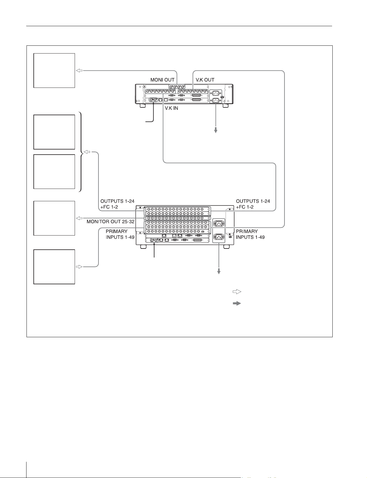
Flow of Video Signals
Monitor
Monitor
VTR
Monitor
Camera,
VTR,
routing
switcher
MVE-8000A-C DME
Processor Pack
Reference video signal
d)
Reference video signal
c)
100 to 240 V AC power supply
MVS-6000 Multi Format
Switcher Processor
c)
a)
100 to 240 V AC power supply
b)
a) For the AC power cord of the MVE-8000A, refer to the MVE-
8000A Operation Manual.
b) For the AC power cord of this unit, see page 14.
Video input signal, Video output signal
AC power supply
c) Terminate with the supplied 75Ω terminators.
d) With MKE-8021A installed.
12
Example System Configuration
Page 13
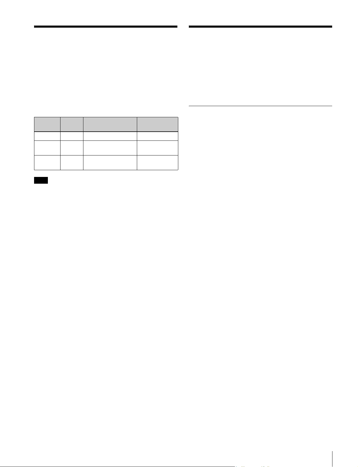
Power Supply Unit Status Indicators
The power supply unit status indicators show the status of
the power supply unit during operation and when the unit
is powered on. Whenever a power error is detected, it is
reflected immediately by the indicator.
Specifications
The following specifications show the reference
performance for this unit and individual option boards/
units.
Design and specifications are subject to change without
notice.
Meaning of status indicator displays
Indicator
color
Green Lit Operating normally −
Red Lit Power supply unit fan
− Not lit Power supply unit
Note
When the unit is powered on, the status indicators may
light momentarily in red and a whining sound may be
heard. This is not a malfunction. Power all of the installed
power supply units on.
Status Description Steps to take
fault
fault
Exchange the
fan unit
Exchange the
power unit
MVS-6000 Multi Format Switcher Processor
General
Power requirements
100 to 240 V ±10% AC, 50/60 Hz
Current consumption
100 V: 7 A, 240 V: 3 A
Peak inrush current
(1) Power ON, current probe method: 42
A (100 V), 45 A (240 V)
(2) Hot switching inrush current,
measured in accordance with
European standard EN55103-1: 36 A
(230 V)
Operating temperature
5ºC to 40ºC (41ºF to 104ºF)
Performance guaranteed temperature
10ºC to 35ºC (50ºF to 95ºF)
Storage temperature
−20ºC to +60ºC (−4ºF to +140ºF)
Operating humidity
10% to 90%
Dimensions (w/h/d, excluding projections)
482×176×520 mm (19×7×20
Mass Approx. 26 kg (57 lb 5.1 oz) (when
equipped with all installable option
boards and option power supply unit)
1
/2 inches)
Remote control connectors
CTRL RJ-45, Complies with 100Base-TX
standard
DATA RJ-45, Complies with 100Base-TX
standard
REMOTE 1, 2, 3, 4
D-sub 9-pin, female
Comply with RS-422A standard
Data transfer rate: 38.4 Kbps
GPI D-sub 25-pin, female
TTL inputs: 8
Relay contact outputs: 4 (30 V AC/DC,
0.1 A)
Open collector outputs: 4
Power Supply Unit Status Indicators / Specifications
13
Page 14

Reference input
REF INPUT BNC type, 75Ω with loop-through output
HDTV system: HD tri-level sync/SDTV
analog black burst/SDTV analog sync
SDTV system: Analog black burst/
analog sync
Return loss –40 dB
Frame memory input and output
FM DATA RJ-45, complies with 100Base-TX
standard
FM DEVICE Complies with IEEE1394
Note
Always verify that the unit is operating properly before
use. SONY WILL NOT BE LIABLE FOR DAMAGES
OF ANY KIND INCLUDING, BUT NOT LIMITED
TO, COMPENSATION OR REIMBURSEMENT ON
ACCOUNT OF THE LOSS OF PRESENT OR
PROSPECTIVE PROFITS DUE TO FAILURE OF
THIS UNIT, EITHER DURING THE WARRANTY
PERIOD OR AFTER EXPIRATION OF THE
WARRANTY, OR FOR ANY OTHER REASON
WHATSOEVER.
Video input
Inputs 15 (BNC-type)
Signal format SMPTE292M/SMPTE259M-C
Signal level 0.8 Vp-p ±10%
Signal transfer rate
1.5 Gbps/270 Mbps
Return loss −15 dB
Cable length HDTV system: 100 m (5C-FB cable,
BELDEN1694 or equivalent)
SDTV system: 200 m (5C-FB cable,
BELDEN1694 or equivalent)
Video output
Outputs 24 (BNC-type)
1, 2, 13 to 16: BNC 2 outputs
3 to 12, 17 to 24, FC1, FC2: BNC 1
outputs
Signal format SMPTE292M/SMPTE259M-C
Signal level 0.8 Vp-p ±10%
Signal transfer rate
1.5 Gbps/270 Mbps
Return loss –15dB
AC input
AC IN A, B 3-pin AC connector
MKS-6470 DME Board Set
Power requirements
DC 12 V DC
Power consumption
Max. 100 W
Dimensions (w/d)
DVP-49 board: 317×380mm (12
inches)
CA-54 board: 317×380mm (12
inches)
Mass 3 kg (6 lb 9.8 oz)
Accessories supplied
Operation and Installation Guide (1)
(supplied only when product is
purchased separately)
MKS-8110G 17-Input Board
General
Power requirements
12 V DC
Power consumption
Max. 10 W
Dimensions (w/d)
274×94 mm (10
Mass Approx. 1 kg (2 lb 3.3 oz)
7
/8×33/4 inches)
1
/2×15
1
/2 ×15
Accessories supplied
75Ω terminator (1)
Brackets (4)
Support angles (2)
Screws (+B4×10) (8)
Screws (+PSW4×10) (8)
Operation Manual (1)
Installation Manual (1)
Accessories not supplied
AC power cord (for USA and Canada only) (125 V 10 A
2.4 m (8 ft)) (Part No.: 1-551-812-31)
AC power cord (for Europe only) (250 V 10 A 2.4 m
(8 ft)) (Part No.: 1-782-929-12)
14
Specifications
Input
Inputs 17 (BNC-type)
Signal format SMPTE292M/SMPTE259M-C
Signal level 0.8 Vp-p ±10%
Signal transfer rate
1.5 Gbps/270 Mbps
Return loss −15 dB
Cable length HDTV system: 100 m (5C-FB cable,
BELDEN1694 or equivalent)
SDTV system: 200 m (5C-FB cable,
BELDEN1694 or equivalent)
Page 15

Accessories supplied
Operation and Installation Guide (1)
(supplied only when product is purchased separately)
(supplied only when product is purchased
separately)
HK-PSU04 Power Supply Unit
MKS-8161M Monitor Output Board
General
Power requirements
12 V DC
Power consumption
Max. 10 W
Dimensions (w/d)
274×94 mm (10
Mass Approx. 1 kg (2 lb 3.3 oz)
Output
Outputs 8 (BNC-type), each with 2 outputs
Signal format SMPTE292M/SMPTE259M-C
Signal level 0.8 Vp-p ±10%
Signal transfer rate
1.5 Gbps/270 Mbps
Return loss –15 dB
Accessories supplied
Operation and Installation Guide (1)
(supplied only when product is purchased separately)
7
/8×33/4 inches)
Power requirements
Input power: 100 to 240 V ±10% AC,
50/60 Hz
Output power: 12 V DC ±0.3 V
Current consumption
10 to 5 A
Secondary power supply
Max. 60 A
Dimensions (w/h/d)
94×83×396 mm (3
Mass Approx. 3 kg (6 lb 9.8 oz)
Accessories supplied
Operation and Installation Guide (1)
(supplied only when product is
purchased separately)
3
/4×33/8×155/8 inches)
MKS-8442G Frame Memory Board
Power requirements
12 V DC
Power consumption
Max. 100 W
Dimensions (w/d)
317×380 mm (12
Mass Approx. 2 kg (4 lb 6.5 oz)
Accessories supplied
Operation and Installation Guide (1)
(supplied only when product is
purchased separately)
1
/2×15 inches)
MKS-8450G Format Converter Board
Power requirements
12 V DC
Power consumption
Max. 50 W
Dimensions (w/d)
317×380 mm (12
Mass Approx. 1.5 kg (3 lb 4.9 oz)
Accessories supplied
Operation and Installation Guide (1)
1
/2×15 inches)
Specifications
15
Page 16

Page 17

The material contained in this manual consists of information
that is the property of Sony Corporation and is intended solely
for use by the purchasers of the equipment described in this
manual.
Sony Corporation expressly prohibits the duplication of any
portion of this manual or the use thereof for any purpose other
than the operation or maintenance of the equipment described
in this manual without the express written permission of Sony
Corporation.
Page 18
.
MVS-6000
(SY)
4-144-243-01 (1)
Sony Corporation
Printed on recycled paper.
Printed in Japan
2009.03 13
© 2009
 Loading...