

Sony Multiscan CPD-1604S, Multiscan CPD-1604SA Service Manual

SERVICE
MANUAL
REVISED
SPECIFICATIONS
US Model
Canadian Model
Chassis
No.
SCC-E72A-A
Multiscan
Picture tube
Viewable pixels
Scanning frequency
Video input signal
Sync input
Power requirements
Super
Fine Pitch T rinitron color tube
17-inch (16
90 degree deflection
Anti-glare dark screen
Phosphor P22
0.25
1024 x 768
Vertical sync signal frequency:
50Horizontal sync signal frequency:
28 - 57 kHz
Analog RGB positive
0.714 Vp-p1750 terminated
TIL
Composite sync is acceptable at Pin #
Sync on green
100-120 V AC, Max. 2.0
220-240 V AC, 1.0
V)
picture tube measured diagonally
mm
Aperture Grille Pitch
87 Hz
level. Polarity free.
is
acceptable.
A,
A,
50-60
50-60
Hz
Hz
Dimensions
.
I
p
300 rnrn
406 rnrn
'1
8.
Weight
Supplied accessory
Design and specification subject
430(H) x 406(W) x 437(0)
(17 x
16
-
-r
I
Approx. 20
Including the tilt-swivel
AC
power cord (1)
x 17'/4 inches)
E
E
0
M
".
E I
~T
I
kg
to
change without notice.
I
mm
300
~
io) III'
I;)
Ill'
I
rnrn
437mm
...dlll..
/
I
•••••
•••••
•••
MICROFILM
COLOR
COMPUTER
SONY:
MULTISCAN®
DISPLAY

CPD-1604S/1604SA
WARNING
To
prevent fire
to rain
or
Dangerously high voltage is present inside the unit. Do
not open the cabinet. Refer servicing to qualified
personnel only.
or
moisture.
shock hazard, do not expose the unit
NOTE:
This
limits for a
These
limits
interference
ment.
This
energy
and,
manual,
may
tion
of
this
interference
ence
at
his
'You
are
cautioned
approved in
ment."
equipment
Class
A digilal device,
are
designed
when
the
equipment
if notlnslalled
cause
harmful
equipment
in
which
own
expense.
that
this
manuaf
has
been
to
provide
equipment
generates,
and
used
interference
in a residential
case
the
user
any
changes
could
void
tested
pursuant
reasonable
is
operated
uses,
and
in
accordance
area
will
be
or
your
and
found
to
to
Part
15
protection
in a commercial
can
radiate
to
radio
communications.
is
likefy
to
required
modifications
authority
to
comply
of
the
radio
with
the
cause
to
correct
not
operate
with
FCC
against
environ·
frequency
instruction
harmful
the
expressly
this
equip-
the
Rules.
harmful
Opera-
interfer-
TABLE
Section
1. GENERAL
1-1.
Location
1-2.
Connections···································· .. ···· .. · ............... 5
1-3.
Use
of
the
1-4.
Timing Chart·························································· 7
2.
DISASSEMBLY
2-1.
Tilt
and
Cabinet Removal· ........................................ · 9
2-2.
DA(DC-l) board Removal ................ · .... · .................. 9
2-3. Chassis
and
2-4. D Board Removal .................................. · .. · ..............
2-5. Picture Tube Removal ..............................................
3.
SET-UP ADJUSTMENTS
3-1.
Beam
Landing ........ ·· ........ ·· ...... · ............................
3-2. Convergence···································· .. ······ .. ·········· ..
3-3. Focus Adjustment
3-4. White Balance ........................................ · ..............
3-5.
Bright Controllable Confirmation ...............................
Title
and
Function of Controls ...... · ........ ·.............. 4
Tilt-Swivel· ............ · ................ · .............. · 6
B Block Assembly Removal ................ · .... ·
..
· .... · .... · ............ ·· ........................ ·
10
11
11
·12
·13
16
·16
16
OF
CONTENTS
Section
4.
SEFETV RELATED ADJUSTMENT·
5.
CIRCUIT ADJUSTMENTS
5-1.
5-2. D
6.
DIAGRAMS
6-1.
6-2.
6-3.
7.
EXPLODED VIEWS·· ................................................
8.
ELECTRICAL PARTS LIST·· ..............
Title
...... " .....
DA(DC-
1)
Board Adjustment ................ ··· ......
and
DA(DC-J) Board Adjustments ..........................
··
...... ·
'"
Circuit Boards Location ............................................
Schematic Diagrams
and
Printed Wiring Boards ............
Frame Schmatic Diagram····································
DA(OC-1) Board .................... · ..............
D
,K
Board ........
B Board .... · ...... ·
··
............................................ ·
..
· ................ · ...... · .................... 44
Semiconductors .......... · .... · ........ · ..................
·· .. · .. ·· .. · 28
··
.... · .... ·
··
....................
..
'17
20
21
24
24
25
36
49
51
52
SAFETY·RELATED
COMPONENTS
&.
ON THE SCHEMATIC
VIEWS
AND
SAFE OPERATION. REPLACE THESE COMPONENTS
SONY PARTS WHOSE
WITH
SHOWN
AS
PUBLISHED
THAT
ARE
IDENTIFIED
CEDURES
REPLACED
IDENTIFIED
IN
IN
THIS
BY
CRITICAL
IN
THIS
WHENEVER
OR IMPROPER OPERATION IS SUSPECTED.
COMPONENT
THE PARTS
MANUAL
SONY.
TO SAFE OPERATION
MANUAL.
CRITICAL
WARNING
BY
SHADING
DIAGRAMS,
LIST
ARE
CRITICAL
PART
NUMBERS APPEAR
OR
IN
SUPPLEMENTS
CIRCUIT
ADJUSTMENTS
FOLLOW THESE PRO-
COMPONENTS ARE
!!
AND
MARK
EXPLODED
TO
ARE
ATTENTION
LES COMPOSANTS
PAR UNE
LES VUES EXPLOSEES
SONT
D'UNE
SECURITE
PLACER QUE PAR DES COMPOSANTS SONY
NUMERO DE PIECE EST
MANUEL
SONY. LES REGLAGES
TANCE
FONCTIONNEMENT
PRESENT
DE
CHAQUE
CRITIQUES,OU
MENT
EST SUSPECTE.
AUX
MARQUE
IMPORTANCE
DU
FONCTIONNEMENT.
OU
DANS
EST
CRITIQUE
MANUEL.
REMPLACEMENT
LORSQU'UN
COMPOSANTS
SECURITEII
IDENTIFIES
&SUR
DES SUPPLEMENTS PUBLIES PAR
DE
SONT
SUIVRE
PAR
LES SCHEMAS DE PRINCIPE,
ET
LES LISTES DE PIECES
CRITIQUE
INDIQUE
CIRCUIT
POUR
IDENTIFIES
CES PROCEDURES LORS
MAUVAIS
-2-
RELATIFS A LA
UNE
TRAME
POUR
NE LES REM-
DANS
LA
DE COMPOSANTS
DONT
LE
PRESENT
DONT
L'IMPOR-
SECURITE
DANS LE
FONCTIONNE-
ET
LA
LE
DU
CPD-1604S/1604SA
After
correcting
perform
the
2. Check
3.
4. Look for
5. Look for parts
6. Check the line
7.
the
following
set
to
the
customer:
I.
Check
the
area
poorly-soldered
board
surface
the
wires are
resistors.
Check
ground
been
have replaced all
ticularly
previous repair.
and
obvious
to
the
ment.
Recommend
cord
Check
values specified. Make
are
if sets
"pinched"
that
straps,
replaced.
unauthorized
transistors,
recommend
signs
customer
to
the
the
accurate;
always
the
safety
of
your
connections.
for
solder
interboard
all
control
and
Be
absolutely
the
that
Point
their
which,
of
deterioration.
and
cord
the
replacement
customer.
B+
and
HV to see
be
suspicious
have low HV.
SAFETY
original service
checks
before
repair
for
unsoldered
Check
splashes
wiring
or
con
knobs,
mounting
insulators.
replacement
were
them
replacement.
though
recommend
for
sure
and
to
ensure
tact high-wa
shields,
hardware
certain
installed
out
to
the
functioning.
Point
their
cracks
and
of
any
they
your
of
your
(US
problem,
releasing
or
the
entire
c bridges.
that
no
ttage
covers,
have
that
you
parts,
par-
during
customer
show
them
out
replace-
abrasion.
such
line
are
at
the
instruments
HV
meter
CHECK-OUT
Model Only)
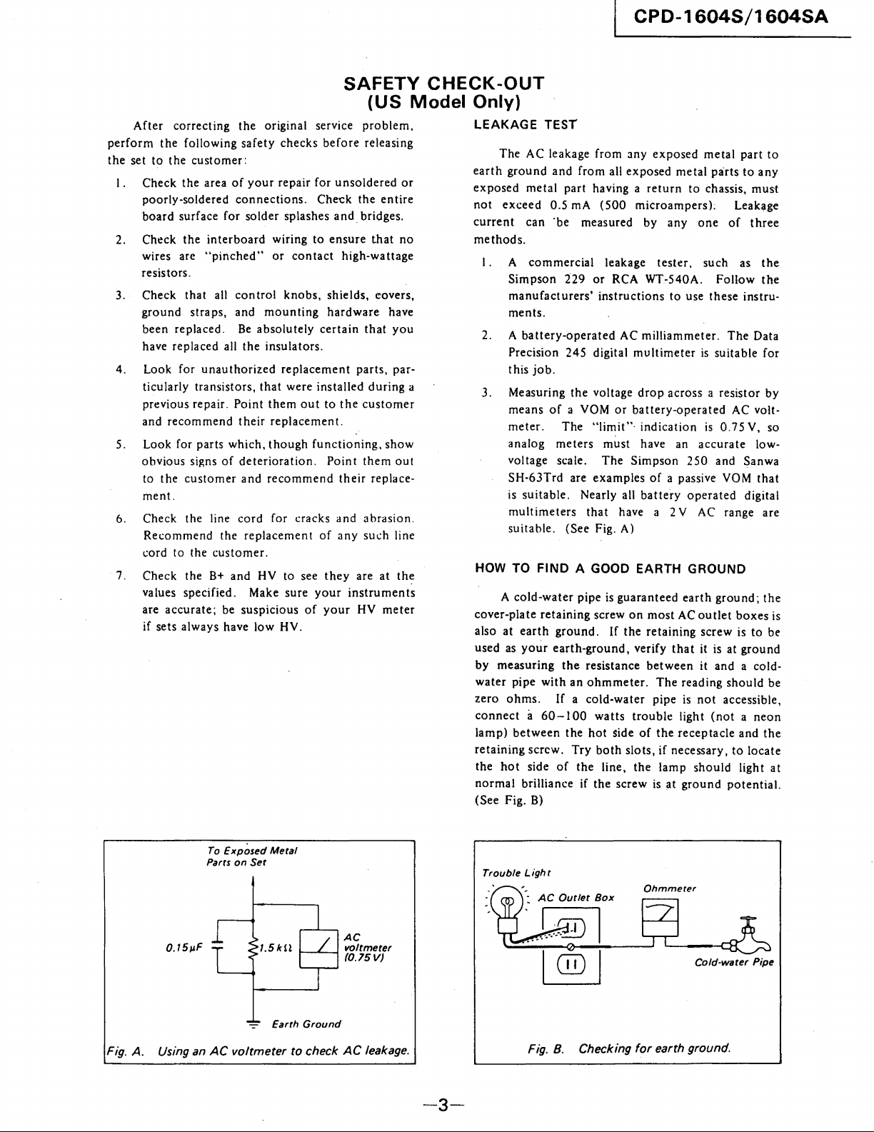
LEAKAGE TEST
The
earth
ground
exposed
not
exceed
current
methods.
I . A
Simpson
2. A
a
3. Measuring
meter.
analog
voltage scale.
SH-63Trd
is
suitable.
HOW TO
A
cover-plate
at
also
used as
by
measuring
water
zero
ohms.
connect a 60-100
lamp)
retaining
the
hot
normal
(See Fig.
AC leakage
and
from
metal
part
0.5 rnA
can
·be measured
commercial
229
manufacturers'
ments.
battery-operated
Precision
this
means
suitable.
multimeters
cold-water
earth
your
pipe
between
brilliance if
245
job.
of
a YOM
The
meters
(See Fig. A)
FIND
retaining
ground.
earth-ground,
the
with
If a
the
screw.
side
of
B)
the
are
Nearly all
A GOOD EARTH GROUND
pipe
an
Try
the
from
any
exposed
all
exposed
having a
(500
or
instructions
digital
voltage
"limit"·
must
The
examples
that
screw
resistance
ohmmeter.
cold-water
watts
hot
both
line,
the
return
microampers);
by
leakage
RCA WT-540A.
is
If
side
tester.
AC
milliammeter.
multimeter
drop
or
battery-operated
indication
have an
Simpson
of
battery
have a 2 V AC range are
guaranteed
on
most
the
retaining
verify
between
The
pipe is
trouble
of
the
slots,
if
the
lamp
screw
is
metal
metal
to
chassis,
anyone
such as
to
use
is
across a resistor
is
accurate
250
a passive YOM
operated
earth
AC
outlet
screw
that
it is at
it
reading
not
light
receptacle
necessary,
should
at
ground
part
to
parts
to
any
must
Leakage
of
three
the
Follow
these
suitable
and Sanwa
ground;
and
(not a neon
the
instru-
The
Data
for
AC volt-
0.75
V. so
low-
that
digital
the
boxes
is
to
ground
a cold-
should
accessible,
and
the
to
locate
Iigh
tat
potential.
by
be
be
is
Fig. A. Using an
To
Parts
AC
Exposed
Metal
on
Set
-=-
Earth
voltmeter
Ground
to check
AC
voltmeter
(0.75
V)
AC
leakage.
-3-
Trouble Ligh t
-:
AC
Fig. 8. Checking
Outlet
Box
Ohmmeter
for
earth ground.
Cold-water Pipe
CPD-1604S/1604SA
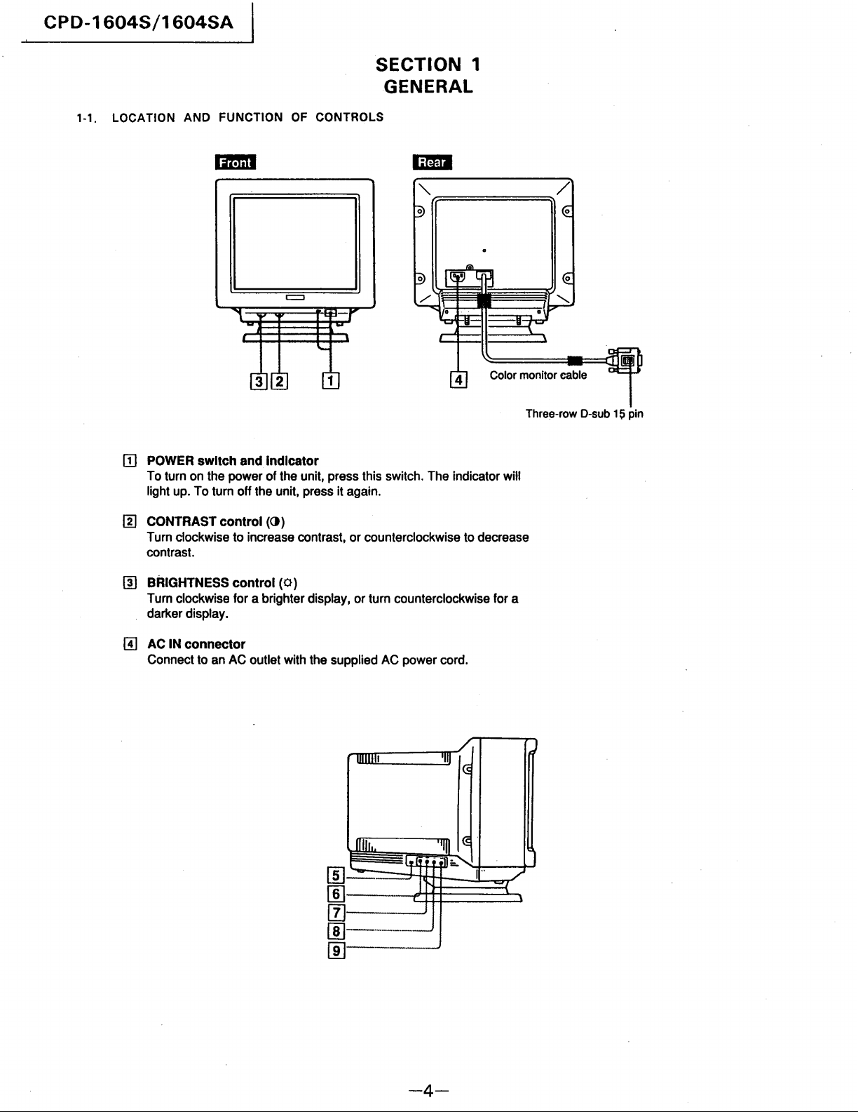
1-1. LOCATION AND FUNCTION
ITI
POWER
To turn on the power of the unit, press this switch. The indicator will
light up. To turn off the unit, press it again.
switch
and
Indicator
OF
=
CONTROLS
1
SECTION
GENERAL
"r,=====~/
1
Color monitor cable
Three-row D-sub 15 pin
rn
CONTRAST
Turn clockwise to increase contrast, or counterclockwise to decrease
contrast.
[!]
BRIGHTNESS
Turn clockwise for a brighter display, or turn counterclockwise for a
darker display.
GJ
AC
IN
Connect to an AC outlet with the supplied AC power cord.
control
control
connector
())
(0)
Willi!
..IJ.1&
'-
-~
'III
1<5
'ljlll~
.•
11
:.
i [ .. [
.........
I"
--"'--"---
-----------'
-4-
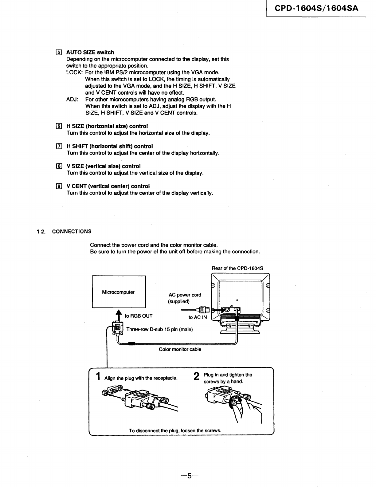
[!)
AUTO SIZE switch
Depending on the microcomputer connected to the display, set this
switch to the appropriate position.
LOCK: For the IBM PS/2 microcomputer using the VGA mode.
When this switch is set to LOCK, the timing is automatically
adjusted to the VGA mode, and the H SIZE, H SHIFT, V SIZE
and V CENT controls will have no effect.
ADJ: For other microcomputers having analog RGB output.
When this switch is set to ADJ, adjust the display with the H
SIZE, H SHIFT, V SIZE and V CENT controls.
[!]
H SIZE (horizontal size) control
Turn this control to adjust the horizontal size of the display.
[f]
H SHIFT (horizontal shift) control
Turn this control to adjust the center of the display horizontally.
[!]
V SIZE (vertical size) control
Turn this control to adjust the vertical size of the display.
Iil V CENT (vertical center) control
Turn this control to adjust the center of the display vertically.
CPD-1604S/1604SA
1-2. CONNECTIONS
Connect the power cord and the color monitor cable.
Be sure to turn the power of the unit off before making the connection.
Rear of the CPO-1604S
Microcomputer
to
RGBOUT
Three-row O-sub 15 pin (male)
1 Align the plug with the receptacle.
AC power cord
(supplied)
~
toAC
Color monitor cable
2 Plug in and tighten the
IN
screws by a hand.
To disconnect the
plug, loosen the screws.
-5-
CPD-1604S/1604SA
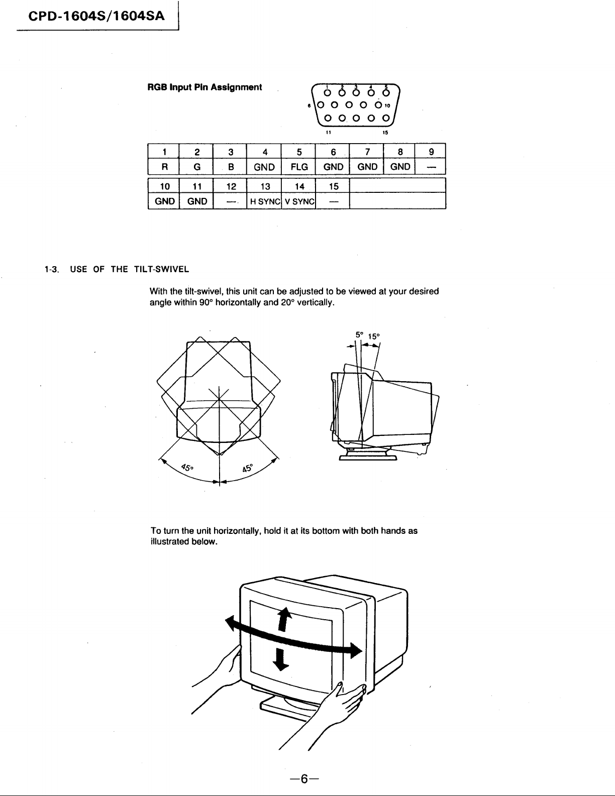
RGB
Input
Pin Assignment
1-3.
USE
I I
I
OF
THE TILT-SWIVEL
11
2 3
R
G~ol
With the tilt-swivel, this unit can be adjusted to be viewed at your desired
angle within 900 horizontally and 200 vertically.
G
G~O
8
12
I
4
GND
I H
~:Ncl
5
FLG
V
~:NCI
G:ol
15
15
G:O
I
G~O
9
I
To turn the unit horizontally, hold it at its bottom with both hands as
illustrated
below.
-6-
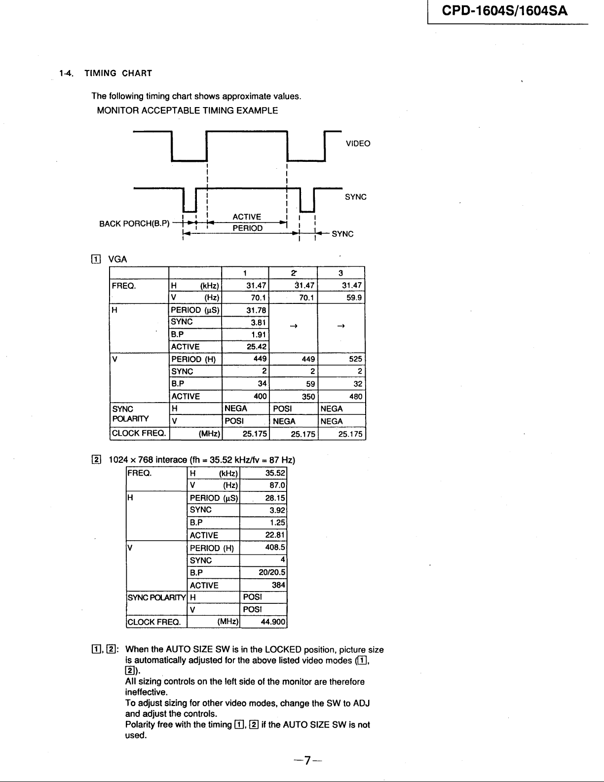
1-4.
TIMING
The
CHART
following timing chart
MONITOR
ACCEPTABLE
shows
approximate values.
TIMING
EXAMPLE
CPD-1604S/1604SA
BACK
PORCH(B.P) -1IIH
[TI
VGA
FREO.
H
V PERIOD
SYNC
POLARITY
CLOCK FREO.
a...._--II
I I
I I
I I
l I I
il
U
I I I ACTIVE I I I
..
·~1
-Ioo1"I---=:P:'::E:::R-:-:IO:'::D:---~·1
.-
I I I
1
H (kHz)
V (Hz)
PERIOD
SYNC
B.P
ACTIVE
SYNC
B.P
ACTIVE
H NEGA
V
(/.lS)
(H)
(MHz)
31.47 31.47
70.1 70.1
31.78
3.81
1.91
25.42
449
2
34
400
POSI
25.175
POSI
NEGA
r-
!.L-J
I I
~I
I.
2"
-+
449 525
2 2
59
350
25.175 25.175
VIDEO
SYNC
SYNC
3
31.47
59.9
-+
32
480
NEGA
NEGA
I]]
[TI,
1024 x
1]]:
768
interace (fh = 35.52 kHZ/fv =
FREO.
H
V
SYNC
POLARITY
CLOCK
FREO.
When
the
is
automatically
1]]).
All
sizing controls
ineffective.
To
adjust
and
adjust
Polarity
used.
free with the timing
H
V
PERIOD
SYNC
B.P
ACTIVE
PERIOD
SYNC
B.P
ACTIVE
H
V
AUTO
SIZE
adjusted
sizing for
the
controls.
87
Hz)
POSI
POSI
I]]
35.52
87.0
28.15
3.92
1.25
22.81
408.5
4
20/20.5
384
44.900
LOCKED
the
monitor
change
if the
AUTO
(kHz)
(Hz)
(IlS)
(H)
(MHz)
SW
is in the
for the above listed video modes
on
the
left side of
other
video modes.
[TI.
position. picture size
([TI.
are therefore
the
SW
to ADJ
SIZE
SW
is not
-7-

CPD-1604S/1604SA
00
35 kHz non-interace (example)
x 600
800
FREQ.
H
V
CLOCKFREQ.
[!] 48 kHz non-interace (example)
1024
x 768
FREQ.
H
V
CLOCK FREQ.
H,
(kHz)
V
PERIOD (IlS)
SYNC
B.P
DISPLAY
PERIOD (H)
SYNC
B.P
ACTIVE
H (kHz)
V (Hz)
PERIOD (IlS)
SYNC
B.P
DISPLAY
PERIOD (H)
SYNC
B.P
ACTIVE
(Hz)
(MHz)
(MHz)
35.16
56.0
28.44
3.11
2.67
22.22
628
14
7
600
36.000
48.780
60.00
20.500
1.500
2.000
16.000
813
3
39
768
64.000
00,
[!]: SYNC POLARITY FREE
[!)
57 kHz non-interace
1024 x 768
FREQ.
H
V PERIOD
CLOCKFREQ.
H (kHz)
V (Hz)
PERIOD .(IlS)
SYNC
B.P
ACTIVE
(H)
SYNC
B.P
ACTIVE
(MHz)
56.476
70.069
17.707
1.813
1.920
13.653
806
6
29
768
75.000
-8-
CPD-1604S/1604SA
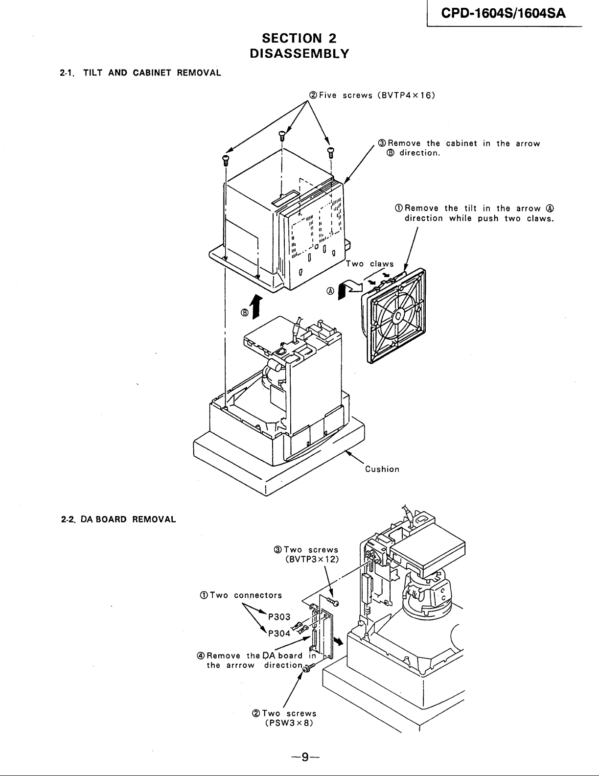
2-1.
TILT
AND
CABINET
REMOVAL
SECTION
2
DISASSEMBL
® Five
Y
screws
(BVTP4 x 16)
CD
Remove
direction
the
while
tilt
in
in
push
the
the
two
arrow
arrow
claws.
®
2-2.
DA
BOARD
REMOVAL
<DTwo
®Two
(PSW3 x 8)
Cushion
screws
-9-
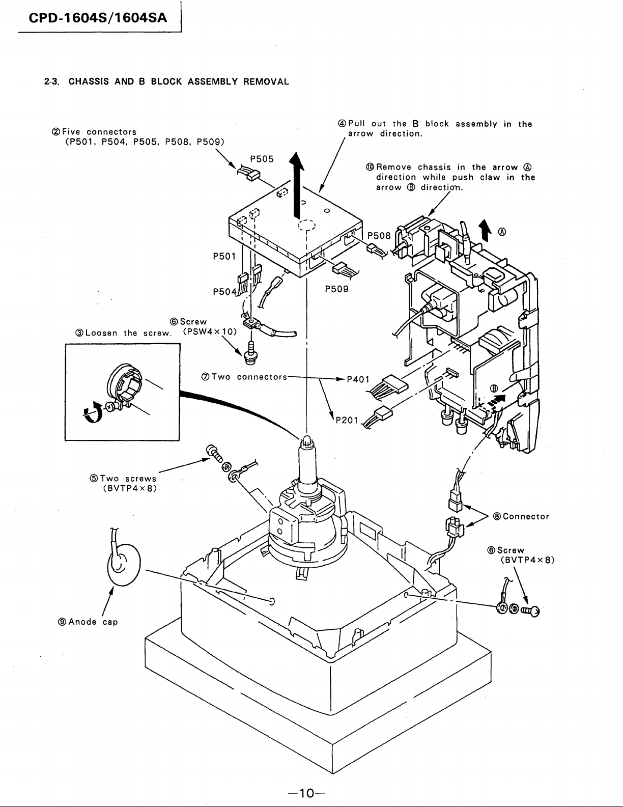
CPD-1604S/1604SA
2-3. CHASSIS AND B BLOCK ASSEMBLY REMOVAL
®
Five
connectors
(P501,
P504.
P505.
P508.
®
Pull
out
arrow
/
the B block
direction.
®>
Remove
direction
arrow @ directio'n.
chassis
while
assembly
in
the
push
claw
in
arrow
in
the
@
the
/
®Anode
cap
-10-
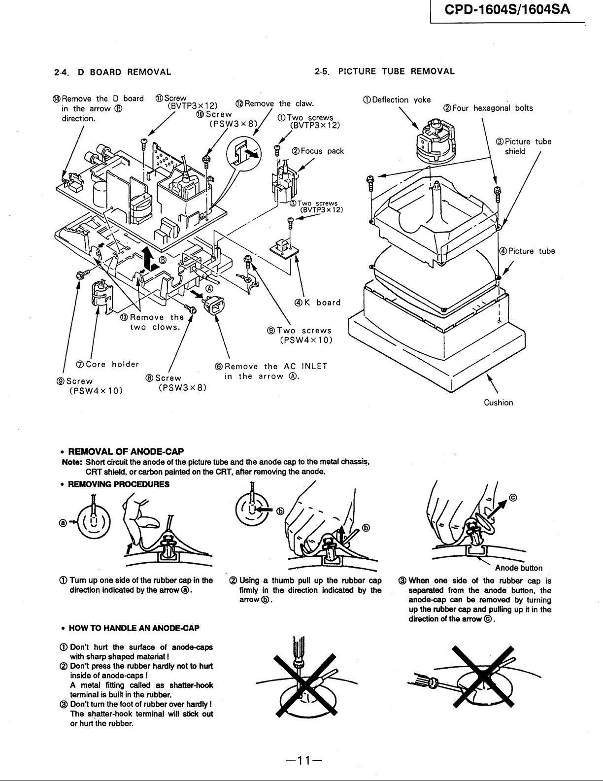
CPD-1604S/1604SA
2-4. D
BOARD
REMOVAL
®
Two
(PSW4x
2-5. PICTURE
pack
@K
board
screws
10)
TUBE
REMOVAL
hexagonal bolts
®
@Screw
Remove
in
the
the
arrow
(PSW4 x 10)
• REMOVAL OF ANODE-CAP
Note: Short circuit the anode of the picture tube and the anode cap
CRT shield,
• REMOVING PROCEDURES
CD
Turn up one side of the rubber cap
direction indicated
• HOW TO HANDLE AN ANODE-CAP
CD
Don't hurt the surface of anode-caps
with sharp shaped material!
or
carbon painted
by
the
aiTow
®.
on
in
the
CRT,
after removing the anode.
the
® Using a thumb pull up the rubber cap
firmly in the direction indicated by the
arrow@.
® Don't press the rubber hardly not to hurt
inside of anode-caps!
A metal fitting called as shatter-hook
terminal is built
@ Don't turn the foot of rubber over hardly!
The shatter-hook terminal will stick out
or
hurt the rubber.
in
the rubber.
AC
®.
INLET
to
the metal
chassi~,
Cushion
Anode button
@ When one side of the rubber cap is
from
separated
anode-cap can be removed by turning
up the rubber cap and pulling up it
direction of the arrow
the anode button, the
in
@ .
the
-11-
CPD-1604S/1604SA
• The following adjustments should
a complete
tube is
•
These
power supply voltage unless ontherwise noted.
The control
unless otherwise noted:
CONTRAST control .........
BRIGHTNESS
realignment
installed.
adjustments
and
switch below should
control .......
is
should.
SET-UP ADJUSTMENT
be
made when
required
or a new picture
be
performed with rated
be
set
as
8096
5096
SECTION 3
follows
Perform the adjustments
3
-1.
Beam
landing
3 -
2.
Convergence
3-3.
Focus
3-4.
White
Balance
Note:
Test Equipment Required.
•
Signal
generator: VG807. VG809 ... etc
• Color Annalyzer
•
Degausser
in
order
(Astro
as
follows:
Design)
Preparation
•
Face
the
PICTURE
not
to
be
influenced by magnetic force.
• T urn
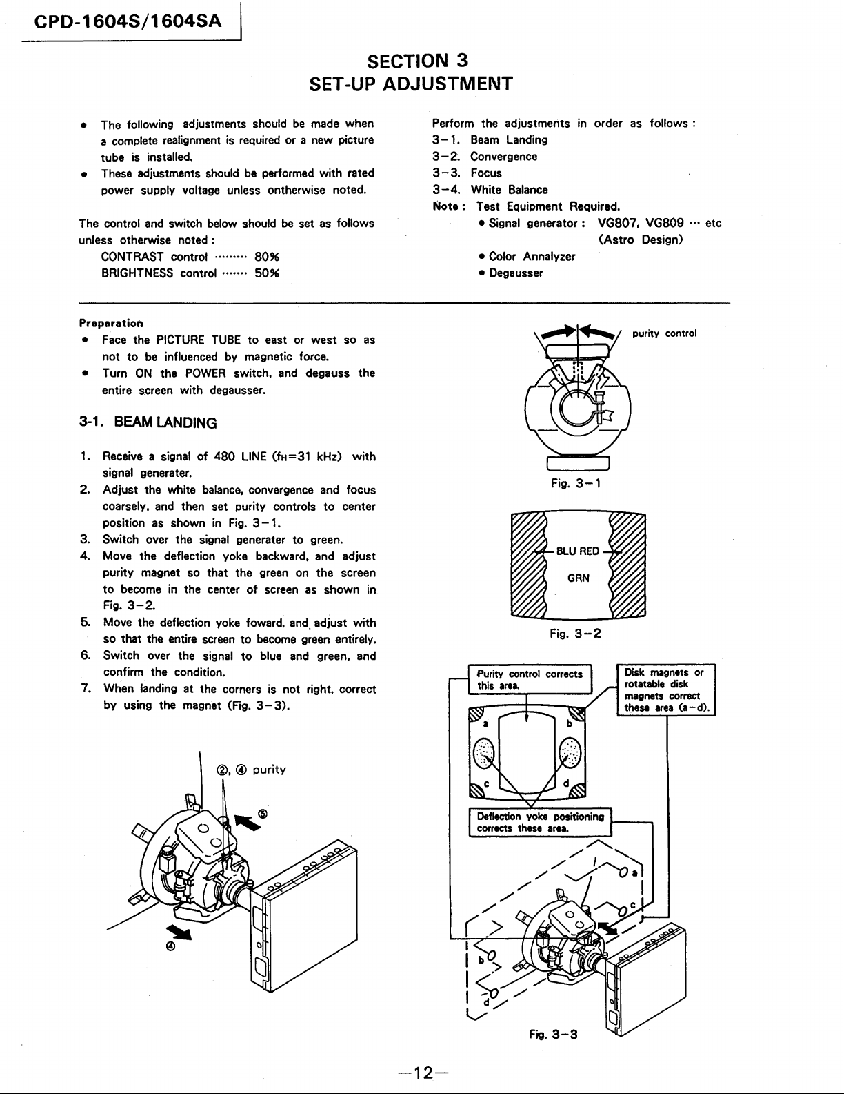
3-1.
1.
2. Adjust the white
3. Switch over the signal
4. Move the deflection yoke backward.
ON
the
entire screen with degausser.
BEAM
Receive
signal generater.
coarsely.
position
purity magnet
to
Fig.
a signal
as
become
3-2.
LANDING
and
in the center
5. Move the deflection yoke foward.
so that the entire
6. Switch over the signal
confirm the condition.
7. When landing at the corners is not right. correct
by using the magnet (Fig. 3 - 3).
TUBE
to
east or west so
POWER
then set purity controls
shown
so
of
480
balance.
in
that the
screen
switch.
LINE
convergence
Fig.
3 -
gene
rater
green
of
screen
to
become
to
blue
and
(fH=31 kHz)
1.
degauss the
with
and
focus
to
center
to
green.
and
adjust
on the screen
as
shown in
and.
adjust with
green
entirely.
and
green.
and
as
Fig.
Fig.
3-1
3-2
purity control
Disk
magnets
rotatable
magnets
these
disk
correct
area
or
(a-d).
-12-
Fig.
3-3
 Loading...