

Sony Multiscan CPD-1404S Service Manual
SERVICE
MANUAL
AEP
Model
•
REVISED
Computer display
Picture tube
Viewable pixels
Scanning frequency
Video input signal
Sync input
Power requirements
Australian
SPECI
FICATIONS
Direct-driven monitor
Super Fine Pitch Trinitron colour tube
V)
14 inch (13
90 degree deflection
Anti-glaring dark screen
Useful screen 274
Phosphor P22
0.25 mm Aperture Grille pitch
1024 x 768
Vertical sync signal frequency:
55
-100Hz
Horizontal sync signal frequency:
28 - 57kHz
Analog
0.714
Vp-pl75n
TIL
level. Polarity free.
Composite sync is acceptable at Pin
Sync on green
100-120
50 -60
picture tube measured diagonally
mm
x 207
mm
RG8
positive
terminated
is
acceptable.
V/220-240 V AC,
Hz,
1,8 - 1,0 A
UK
Chassis
Model
No.
SCC-040B-A
Model
Chassis
No.
SCC-040C-A
Multiscan
#
8.
••
11
MICROFILM
---
COLOUR.
COMPUTER
SONY:·
-
Continued
on
next
page -
MUlTISCAN®
DISPlAYs-
CPD-1404S
c
..
p
mm
mm
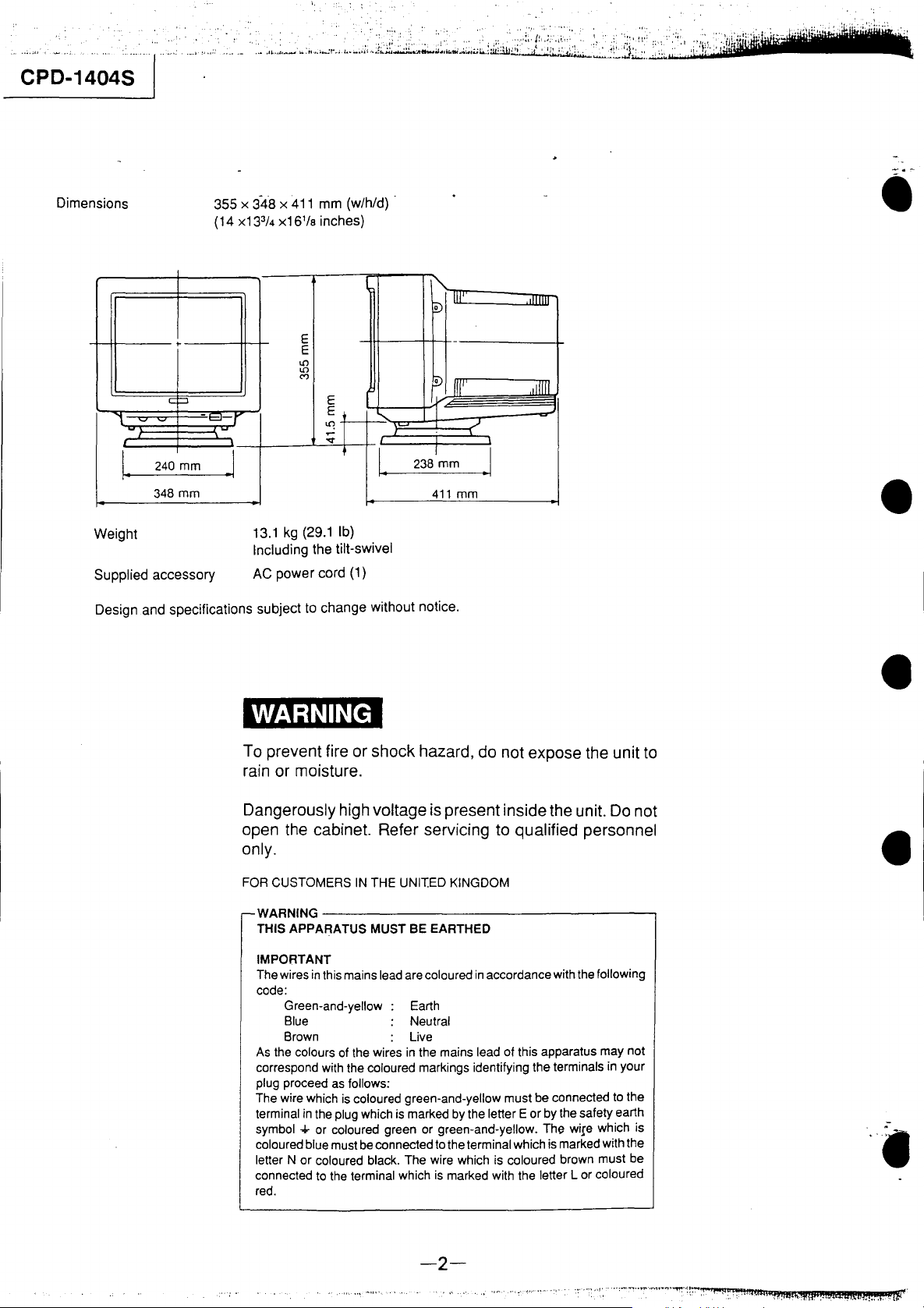
355 x
(14 x13
-
348 x
411
3
/4
x161/a
-r
~
J
13.1 kg (29.1 Ib)
Including
AC power cord (1)
mm (w/h/d) .
inches)
E
E
\0
lO
M
E
E +
~I
f
the tilt-swivel
Dimensions
..,
-
240
I.
348
Weight
Supplied accessory
Design and specifications subject to change without notice.
"'-
I.
238
1"\
~
Iv
y
I
I
mm
411
III"
III"
mm
•
TTTIT
,iITn
./
.1
•
WARNING
To prevent fire or shock hazard, do not expose the unit to
rain or moisture.
Dangerously high
open the cabinet. Refer servicing to qualified personnel
only.
FOR CUSTOMERS
WARNING----------------------------------~
THIS APPARATUS MUST
IMPORTANT
The wires
code:
As the colours of the wires
correspond with the coloured markings identifying the terminals
plug proceed as follows:
The wire which is coloured green-and-yellow must be connected to the
terminal
symbol
coloured blue must be connected to the terminal which is marked with the
letter N or coloured black. The wire which is coloured brown must be
connected to the terminal which is marked with the letter L or coloured
red.
in
this mains lead are coloured
Green-and-yellow:
Blue Neutral
Brown Live
in
the plug which is marked by the letter E or by the safety earth
... or coloured green or green-and-yellow. The wire which is
voltage is present inside the unit. Do not
IN
THE UNIT.ED KINGDOM
BE
EARTHED
in
accordance with the following
Earth
in
the mains lead of this apparatus may not
in
your
•
•
--2--
.
,.-
.,,...'
..
'~.
~'I'"
~
.•
",.
•••
.
~.
'IIi'
.
:,
'
..
:~
'
..
iII.~_~~ikalii~~~b!ii.llb,ihi!.\~h~ih'"
~·i.,ilW.l~t~:i:.i;:"'I~'
J~!i"~.iiil;;;;~w'~';l;.,~~i\~H>J~'il~:il~lIiji~~L;;i;.;~,,~,,,.{'~J~.~.::li~.i:(i;~';;"
,;;,;':;,,;,L
:,,'
ilH'
"
,'!F
1\:'
....
,I
~;.~t~:'1
TABLE
Section
1.
GENERAL
1-1.
Location
1-2.
Connections··········································· ................. 5
1-3.
Use
of
the
1-4.
Timing Chart·························································· 7
2.
DISASSEMBLY
and
2-1. Tilt
2-2.
2-3. Chassis
Cabinet Removal
DA(DC-I) Board Removal·····································
and
2-4. D Board Removal·
Title -
and
Function
of
Controls ........ ·
..
· .......... · ...... · 4
Tilt·Swivel··········································· ... 6
..
········································ 8
B Block Assembly Removal·
..
·······
..
········································
.. ··
.......... ....... 9
OF
2-5. Picture Tube Removal········ ......................................
3.
SET-UP ADJUSTMENTS
3-1.
Beam
Landing························································
3-2. Convergence··········································· ................
3-3. Focus Adjustment··············· .....................................
3-4. White Balance···························· ............................
3-5.
Bright Controllable Confirmation ...............................
CONTENTS
4.
5.
5-1.
5-2. D
6.
6-1. Circuit Boards Location
..
8
10
10
11
12
15
15
15
6-2. Schematic Diagrams and Printed Wiring Boards· ...........
6-3.
7.
8.
I CPD-1404S
Section
SAFETY RELATED ADJUSTMENT··········· ...............
CIRCUIT ADJUSTMENTS
DA(DC··I) Board Adjustment
and
DA(OC-l) Board Adjustments .........................
DIAGRAMS
Frame Schematic
DA(OC-l) Board··············································
D Board···························································33
B Board···························································40
Semiconductors· ......................................................
EXPLODED ViEWS·················································· 47
ELECTRICAL PARTS LIST
Title
..
··································
..
··································
Diagram······ ............................
'"
...................................
..
······
'_
16
19
20
23
23
24
26
45
48
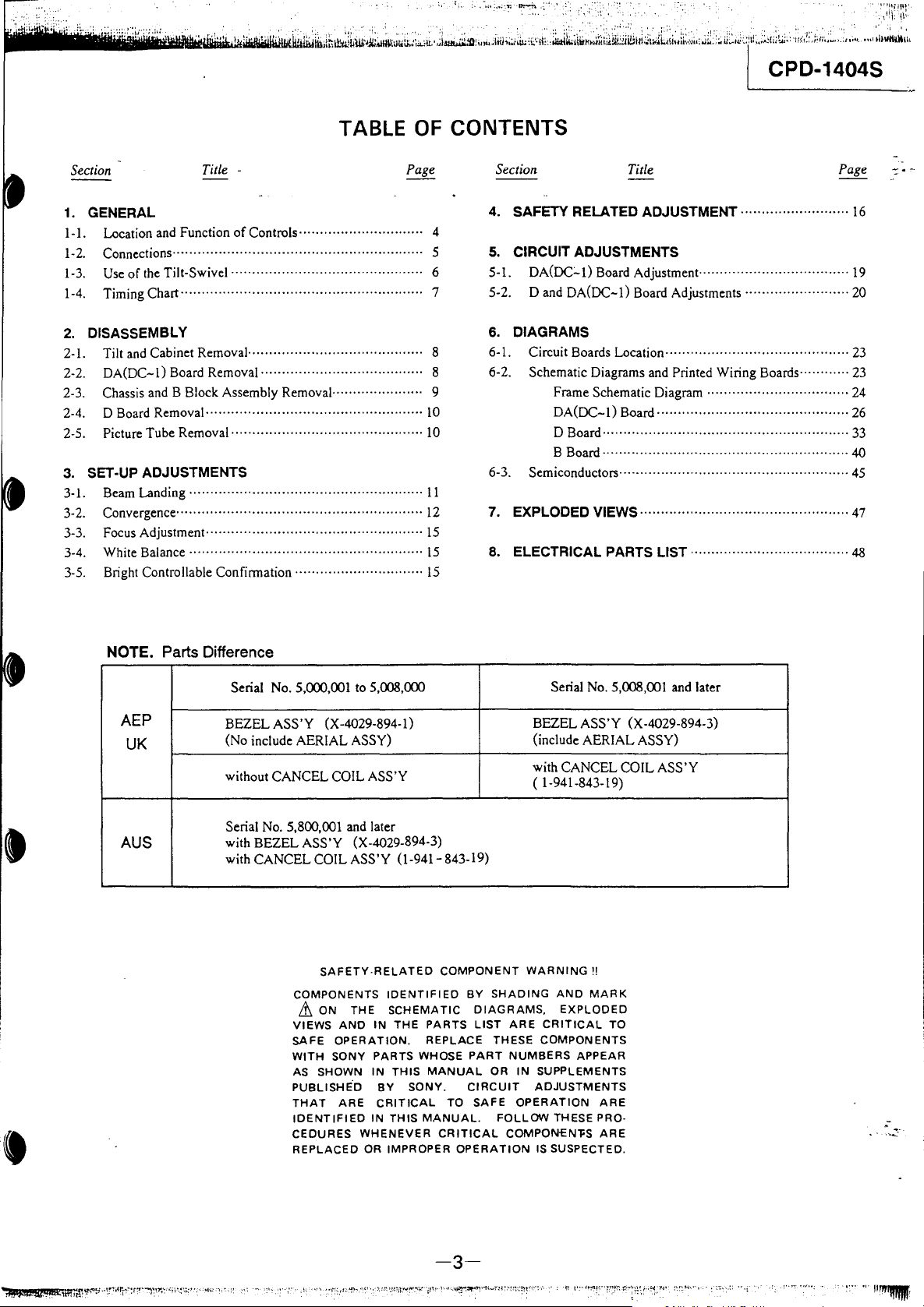
NOTE. Parts Difference
Serial
AEP
UK
AUS
BEZEL ASS'Y
(No include AERIAL
without CANCEL COIL ASS'Y
Serial
No.
BEZEL ASS'Y (X-4029.894-3)
with
with CANCEL
No.
5,000,001
to
5,008,000
(X-4029-894-1)
ASSY)
5,800,001
and
later
COIL ASS'Y (1-941-843-19)
SAFETY·RELATED
COMPONENTS
.&
ON
VIEWS
AND
SAFE
OPERATION.
WITH
SONY
AS SHOWN
PUBLISHE'D
THAT
CEDURES
ARE
IDENTIFIED
REPLACED
IDENTIFIED
THE
SCHEMATIC
IN
PARTS
IN
THIS
BY
CRITICAL
IN
THIS
WHENEVER
OR
IMPROPER
THE
SONY.
COMPONENT
PARTS
REPLACE
WHOSE
MANUAL
TO
MANUAL.
CRITICAL
OPERATION
BY
SHADING
DIAGRAMS,
LIST
ARE
THESE
PART
NUMBERS
OR
CIRCUIT
SAFE
OPERATION
FOLLOW
COMPON-ENl'S
No.
Serial
5,008,001 and later
BEZEL ASS'Y (X-4029-894-3)
(include AERIAL
ASSY)
with CANCEL COIL ASS'Y
( 1-941-843-19)
WARNING
CRITICAL
COMPONENTS
IN
SUPPLEMENTS
ADJUSTMENTS
IS SUSPECTED.
'!
AND
MARK
EXPLODED
THESE PRO·
TO
APPEAR
ARE
ARE
.-
-3-
:"''""':''''''';
"
,.~.
"~'I.;mL..'.;!
CPD-1404S
.--------------~
... , ..
,.,:.~:
..
:~;.;
..
i.:;.,."".
,.;,;
•.
,J:;
....
i'",·~,.;;~~;~i~Jl;.
"
....
;;..;i.~,·~~
..
.........u.;~:.L:i~i2~.;~~,2~~'
SECTION 1
GENERAL
.::
....
, .
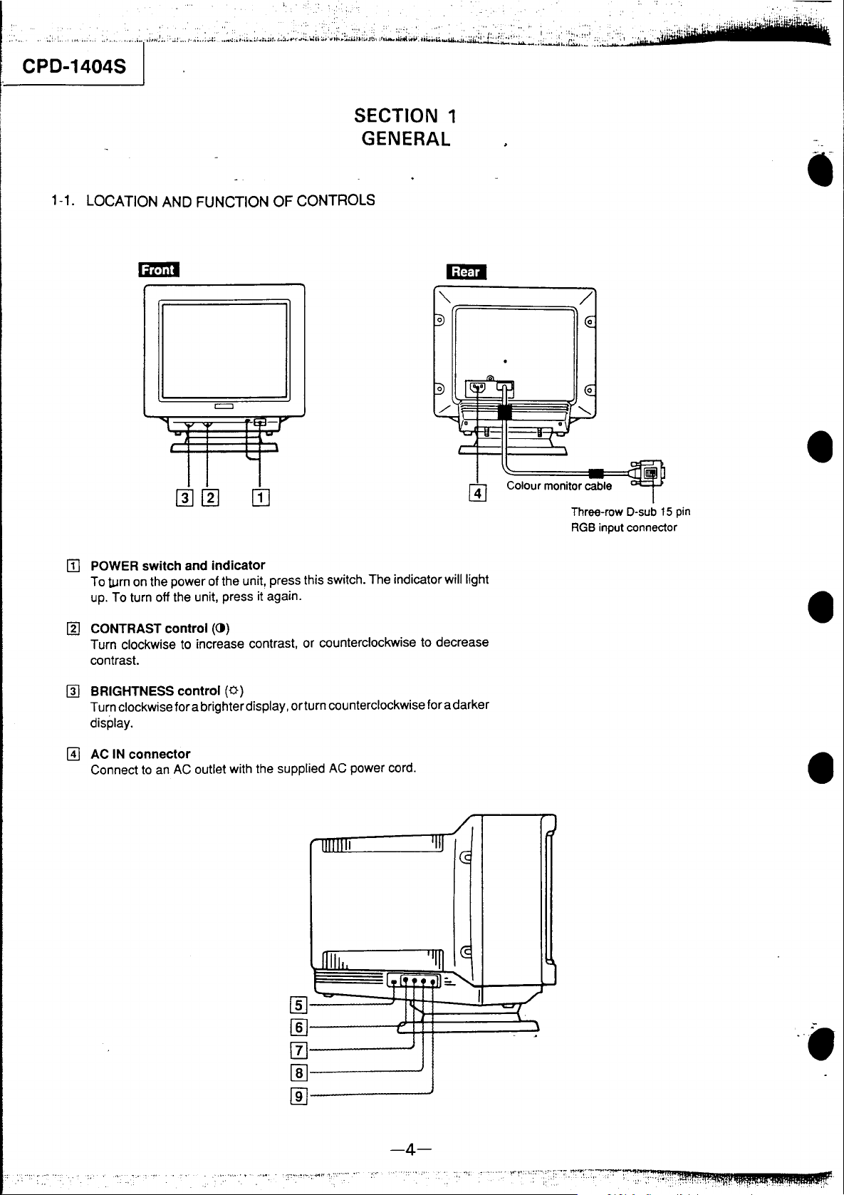
1-1. LOCATION AND FUNCTION OF CONTROLS
-
=
-r
w
'-
.,
III
POWER
To turn on the power of the unit, press this switch. The indicator will light
up. To turn off the unit, press it again.
switch and indicator
"r;=======;-.
Colour monitor cable
•
•
Three-row D-sub 15 pin
RGB input connector
rn
CONTRAST control
Turn clockwise to increase contrast, or counterclockwise to decrease
contrast.
rn
BRIGHTNESS control
Turn clockwise for a brighter display
display.
~
AC
IN
connector
Connect
to
an AC outlet with the supplied AC power cord.
())
(0)
,orturn
Jllllli
c
counterclockwise for a darker
r
1111
'1111
ill:.
Ullilli
:
I.
I~
~
..........
I
•
•
J
]
'/
\
~
,
-4-

1i
•••
iII.Illi.
[i]
[ID
rn
00
__
rillliAnuiL~liIiiIliiildw~~~~Jfu~.iioJ~liii.,;~·~~
AUTO SIZE switch
Depending on the microcomputer connected
switch to the appropriate position.
LOCK: For the IBM PS/2 microcomputer using the VGA mode.
When this switch is set to
adjusted to the VGA mode, and the H SIZE, H SHIFT, V SIZE
and V CENT controls will have
ADJ: For other microcomputers having
When this switch is set to ADJ, adjust the
H SHIFT, V SIZE and V CENT controls.
H
SIZE
(horizontal size) control
Turn this control to adjust the horizontal size of the display.
LOCK, the timing
no
to
the display, set this
effect.
analog RGB output.
display with the H SIZE,
H SHIFT (horizontal shift) control
Turn this control to adjust the centre of the display horizontally.
V SIZE (vertical size) control
Turn this control to adjust the vertical size of the display.
lL.:r
.u.,nd·ti.w~u~.:m!t~h
is
automatically
.•
~.~U.;'~~Ll';":::~I~:';'l1hi
\jh_:~i,,,,;),~i)
......
,
II:
I'
1\:'
..
111
~j"
;~Y:;!.'l~
';U:,.J;
f:n:.'
:\
....
:.t
.....
~,
,H";tt..a.:.:
I CPD-1404S
00
V
CENT
(vertical center) control
Turn this control to adjust the centre of the display vertically.
1-2. CONNECTIONS
Connect the power cord and the monitor cable.
Be sure to turn the power of the unit off before making the connection.
Microcomputer
to
RGB OUT
Three-row O-sub 15 pin (male)
AC power cord
---c::iIld
(supplied)
monitor cable
Colour
toAC
Rear of the CPD-1404S
"'-'=====
t~!~i~~~
IN
1 Align the plug with the receptacle.
To disconnect the
plug, loosen the screws.
-5-
2 Plug
in
screws by hand.
and tighten the
.•
~~~"
-m~'!"~~~:
:'1'~~
..
,
'1
,!~'
:·'··v~!-'
.--: .
...
1-
~~"
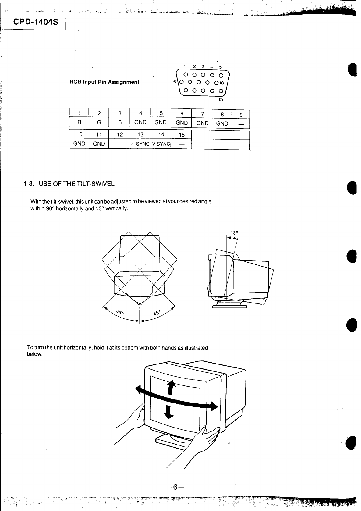
RGB
Input
Pin
Assignment
2
3
4
5
0
0000
6 0 0 0 0 010
00000
11
15
1
R
I
I
G~D
1-3. USE OF THE TILT-SWIVEL
With the tilt-swivel, this unit can be adjusted to be viewed at your desired angle
within 90° horizontally and 13° vertically.
2
G B
I
G~D
I
3
12
I
4
GND
I H
~:Ncl
5
GND
V
~:Ncl
G~D
I
15
9
G~D
I
G~DI
•
•
To turn the unit horizontally, hold it at its bottom with both hands as illustrated
below.
-6-
•
"
.'
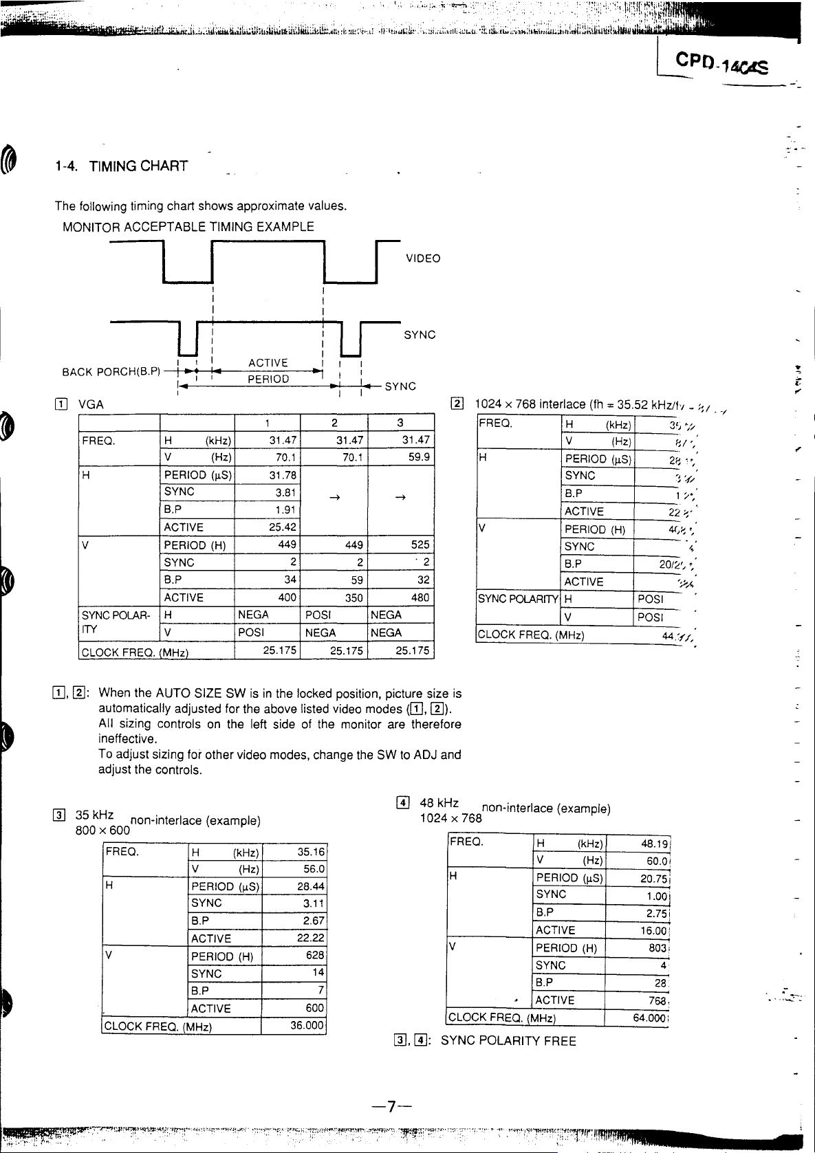
1-4.
TIMING
CHART
The following timing chart shows approximate values.
MONITOR ACCEPTABLE TIMING EXAMPLE
-----'
___
1 I
I I
I I
U i ! U
1
BAC K PORC H(B.
1Il
VGA [Il 1024 x 768 interlace
FREO.
H PERIOD (IlS) 31.78
V PERIOD (H)
SYNC
ITY
CLOCK FREO. (MHz)
P)
POLAR-
,I
---jl--l~_·
-i
1---'
----.:-=:..:==----
,"
H (kHz)
V (Hz)
SYNC
B.P
ACTIVE
SYNC
B.P 34
ACTIVE
H
V
ACTIVE I 1 1
..
e---
O-D--<~~I
-
1
P-E-R
1
31.47
70.1 70.1
3.81
1.91
25.42
449
400
NEGA
pas
I
25.175
2
pas
NEGA NEGA
...
1 VIDEO
SYNC
I '
..
~.j...1
-1;-.
..
..-
SY
I I
2 3
31.47
~
449 525
2
59
350
I
25.175
NC
31.47
59.9
~
'2
32
480
NEGA
25.175
FREO.
H
V
POLARITY
SYNC
CLOCK FREQ. (MHz)
(fh
= 35.52 kHzJb _ ;:1 .
H
(kHz)
V
PERIOD (IlS)
SYNC
B.P
ACTIVE
PERIOD (H)
SYNC
B.P
ACTIVE
H
V
(Hz)
POSI
POSI
3',
f'.
2~
'j
1
22
4(/
20/2'
"
44,~
1'/,
1 "
, ,
" '
, ,
'/
,
W,
[Il: When the AUTO SIZE SW
automatically adjusted for the above listed video modes
All sizing controls
ineffective.
To adjust sizing
for other video modes, change
adjust the controls.
[1]
35
kHz non-interlace (example)
800 x 600
FREO.
H
V
CLOCK FREQ. (MHz)
H (kHz)
V
PERIOD (IlS)
SYNC
B.P
ACTIVE
PERIOD (H)
SYNC
B.P
ACTIVE
is
in
the locked position. picture size is
(W.
on
the left side of the monitor are therefore
the
SW
to
ADJ and
@]
35.16
(Hz)
56.0
28.44
3.11
2.67
22.22
628
14
600
36.000
7
[1],
@]:
[Il).
48 kHz non-interlace (example)
1024 x 768
FREO.
H
V
FREQ. (MHz)
CLOCK
SYNC POLARITY FREE
H
V
PERIOD (IlS)
SYNC
B.P
ACTIVE
PERIOD (H)
SYNC
B.P
,
ACTIVE
(kHz)
(Hz)
19
48.
60.0!
20.75i
00
1.
2.75i
16.00:
803!
28.
768~
64.000;
1
1
4
.-
..
~......:-:.
-7-
CPD-1404S
:
.~:.:..
.
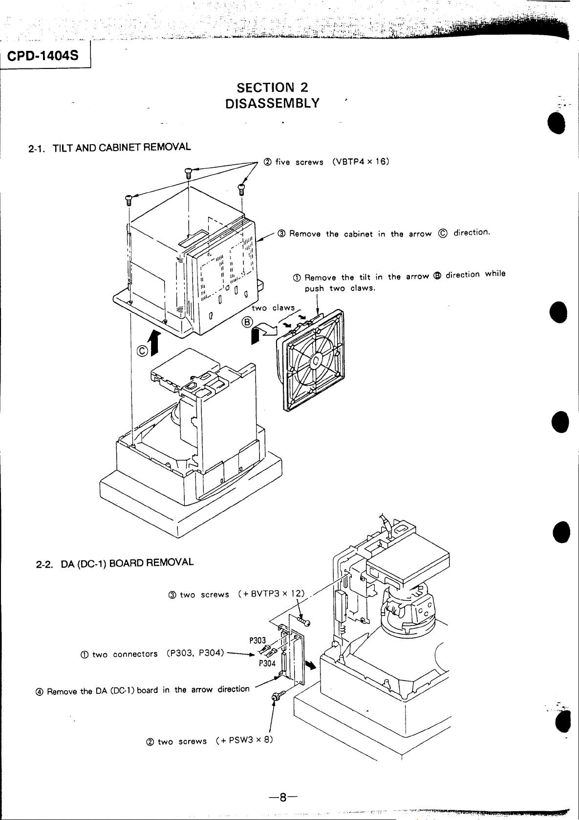
SECTION 2
DISASSEMBL Y
2-1.
TILT
AND
CABINET
REMOVAL
® five
@ Remove
screws
CD
Remove
push
(VBTP4 x
the
cabinet
the
two
claws.
tilt
16)
in
in
the
arrow © direction.
the
arrow
<B>
•
direction while
•
2-2.
DA
@ Remove
(DC-1)
<D
two
the
DA
BOARD
connectors
(DC-1)
board
REMOVAL
®
two
in
the arrow direction
•
•
screws
p
®
two
screws
( + PSW3 x
8)
I
-8-
1
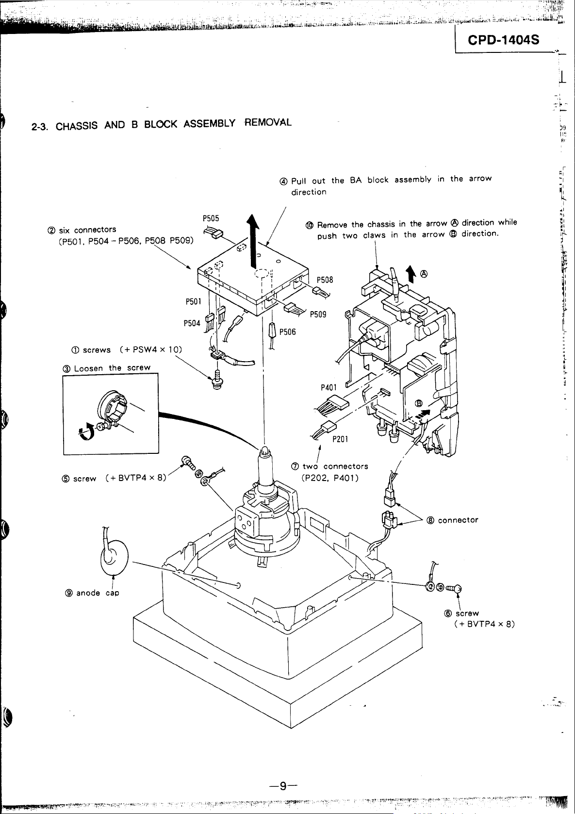
2-3. CHASSIS
@ six connectors
(P50'.
P504 - P506. P508 P509)
<D
",.w,
~
Loo,,"
AND B BLOCK
~
~
( +
PSW4
x 1
tho
,,'Ow
ASSEMBLY
P505
~
.~~:J
';
P50'
P504
jI'~
0)
~
~
REMOVAL
1
~)
, " -
I
I
\.1
I
I)"
@ Pull
direction
@ Remove the chassis in the arrow ® direction while
:>
_
,.
'i
;
/>l
"7~
W-.::
I I
~P509
~
P506
out
push
P508
the
two
SA
block
claws
assembly
in
the
in
arrow
the
<El>
direction.
arrow
j9
II:
R'
\!j~~
@
screw
® anode cap
@
connector
(+
BVTP4 x 8)
.-
-9-
CPD-1404S
. .
" •
~~.'!~i..i
......
~·~:.~~::
••
~~i,
.. (:; ..
dh
..
" ,
•.
,~
..... " •..
.!.:·.u':.'J.u(
.••
t~
•.
~,;.
'.'
.• , ...
·:
..
·',
........
J,lII'::,..:;.ti··.'·:;H.II:.'.··!:
. . . · .' .. ..
.•
::,:t
.......
tt
..
!l:
....
,~~
t'·'W1dHM::.·····--.-_I.1l
~*ijlis;WMiWtrictiRtfidHfL
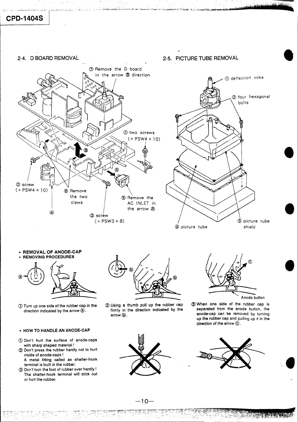
2-4. D BOARD REMOVAL
the
claws
two
(J)
Remove
the 0 board
the
arrow
2-5. PICTURE TUBE REMOVAL
•
•
®
•
REMOVAL
• REMOVING PROCEDURES
CD
Turn
direction indicated
• HOW TO HANDLE AN ANODE-CAP
CD
Don't hurt the surface of anode-caps
with sharp shaped material!
~
Don't press the rubber hardly not
inside of anode-caps!
metal fining called
A
terminal
@ Don't turn the foot of rubber over hardly!
The shaner·hook terminal will stick out
or hurt the rubber.
OF ANODE-CAP
up
one side of the rubber cap
is
built
by
the arrow ®.
in
the rubber.
as
in
the
to
hurt
shaner-hook
(+
PSW3 x
8)
@ Using a thumb pull
firmly
arrow@.
up
in
the direction indicated by the
the rubber cap
@
picture
tube
@ When one side of
separated
anode-cap can
up
the rubber cap and pulling
direction of the arrow
Anode bunon
the
from
the anode bunon, the
be
rubber cap
removed by turning
© .
up
it
tube
in
the
•
•
is
-10-
j "
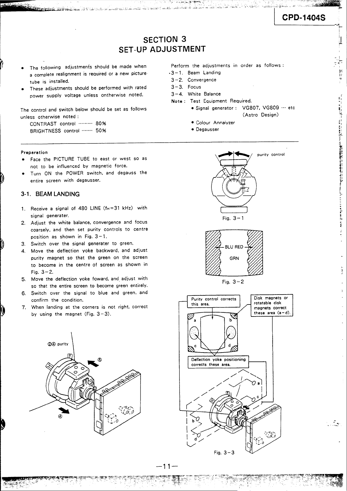
SECTION 3
SET-UP ADJUSTMENT
• The following adjustments should
a complete realignment
is
reQtJifed
be
made when
or
a new picture·
tube is installed.
• These adjustments should
be
performed
with
rated
power supply voltage unless ontherwise noted.
The control and switch below should
unless
otherwise
CONTRAST
BRIGHTNESS
Preparation
•
Face
the PICTURE TUBE
not
to
• Turn
ON
entire screen
3-1.
BEAM
1. Receive a signal
noted:
control·········
control ....... 5096
be
influenced by magnetic force.
the
POWER
with
switch. and degauss the
degausser.
LANDING
of
480
8096
to
LINE
be
east
(fH=31
or
set
as
west
kHz)
follows
so
with
signal generater.
2.
Adjust
coarsely. and then set
position
3. Switch over the signal generater
4. Move the deflection yoke backward. and
purity
to
Fig.
5. Move the deflection yoke foward.
so that the entire screen
6. Switch over the signal
the
white
balance. convergence and
purity
as
shown in Fig. 3 - 1.
controls
to
to
green.
magnet so that the green on the screen
become in the centre
of
screen
as
shown
3-2.
and
adjust
to
become green entirely.
to
blue and green. and
focus
centre
adjust
with
confirm the condition.
7. When landing at the corners is not right. correct
by using the magnet (Fig. 3 -
3).
as
in
Perform the adjustments
.3-
1.
Beam
landing
3 - 2. Convergence
3-3.
Focus
3 - 4. White Balance
Note:
Test Equipment Required.
• Signal
generator:
• Colour Annalyzer
• Degausser
Fig.
Fig.
In
3-1
3-2
order
as
VG807.
(Astro
purity
Disk magnets or
rotatable
magnets correct
these
follows:
VG809
Design)
control
disk
area
... etc
(a-d).
DC
II
'R
r
~
I
"I
~
<ll@
purity
-11-
Fig.
.-
3-3
CPD-1404S
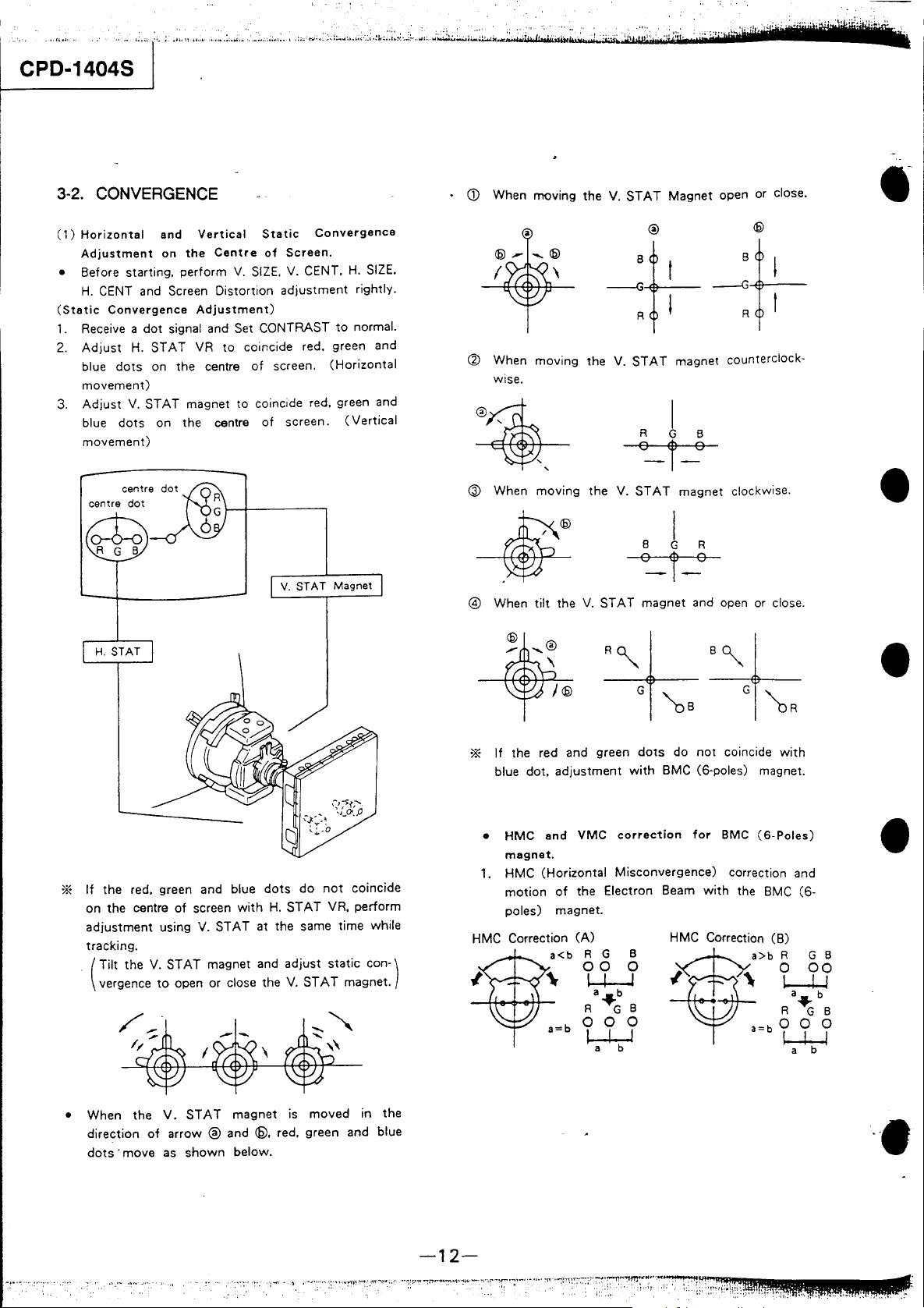
3-2. CONVERGENCE
(1)
Horizontal
Adjustment
• Before starting.
H.
CENT and Screen
(Static
1.
2.
3.
Convergence
Receive a
Adjust
blue
movement)
Adjust
blue
movement)
dot
H.
STAT
dots
on the centre
V.
STAT
dots
on the centre
and
Vertical
on
the
perform
Adjustment)
signal and Set CONTRAST
VR
magnet
Static
Centre
Distortion
of
V.
SIZE.
to
coincide red. green and
of
to
coincide red. green and
of
Convergence
Screen.
V. CENT,
adjustment
screen.
screen.
V.
STAT Magnet
H.
SIZE.
rightly.
to
normal.
(Horizontal
(Vertical
When
CD
~
I
When
wise.
IT1Qving
moving
the V.
'\
the V.
~
@ When
@ When
moving
tilt
the
the
V.
@
close.
•
Magnet open or
STAT
®
-4+-~f,-
R I R I
STAT
magnet counterclock-
I
R
G B
~i~
V.
STAT
magnet
clockwise.
•
STAT
magnet and open or close.
*
If
the red, green and blue
on the centre
adjustment
tracking.
Tilt
(
vergence
• When the
direction
dots'
using V.
the V.
to
of
move
dots
do
of
screen
with
H.
STAT
STAT
at the same time while
STAT
magnet and adjust
open or close the
V,
STAT
magnet
arrow
® and @. red, green and blue
as
shown
below.
V.
is
STAT
not
coincide
VR, perform
static
magnet.
moved
con-)
in the
*
If
the red and green
blue
dot,
adjustment
• HMC
1. HMC (Horizontal Misconvergence) correction and
HMC Correction
and
VMC
magnet.
motion
poles) magnet.
of
the Electron Beam
(A)
a<b
R G B
00
U-J
R
a=b
0 0 0
~
a b
"'G
a b
dots
do
not
with
BMC (6-poles) magnet.
correction
0
B
for
with
HMC Correction (B)
coincide
BMC
(6-Poles)
the BMC (6-
a>b
a=b
with
R G B
o
R
0 0 0
00
l-LJ
a b
"G
B
t.......L-.l
a b
•
•
•••
-12-
".;'
.••
-I
..
.j-::....:'!;·.~
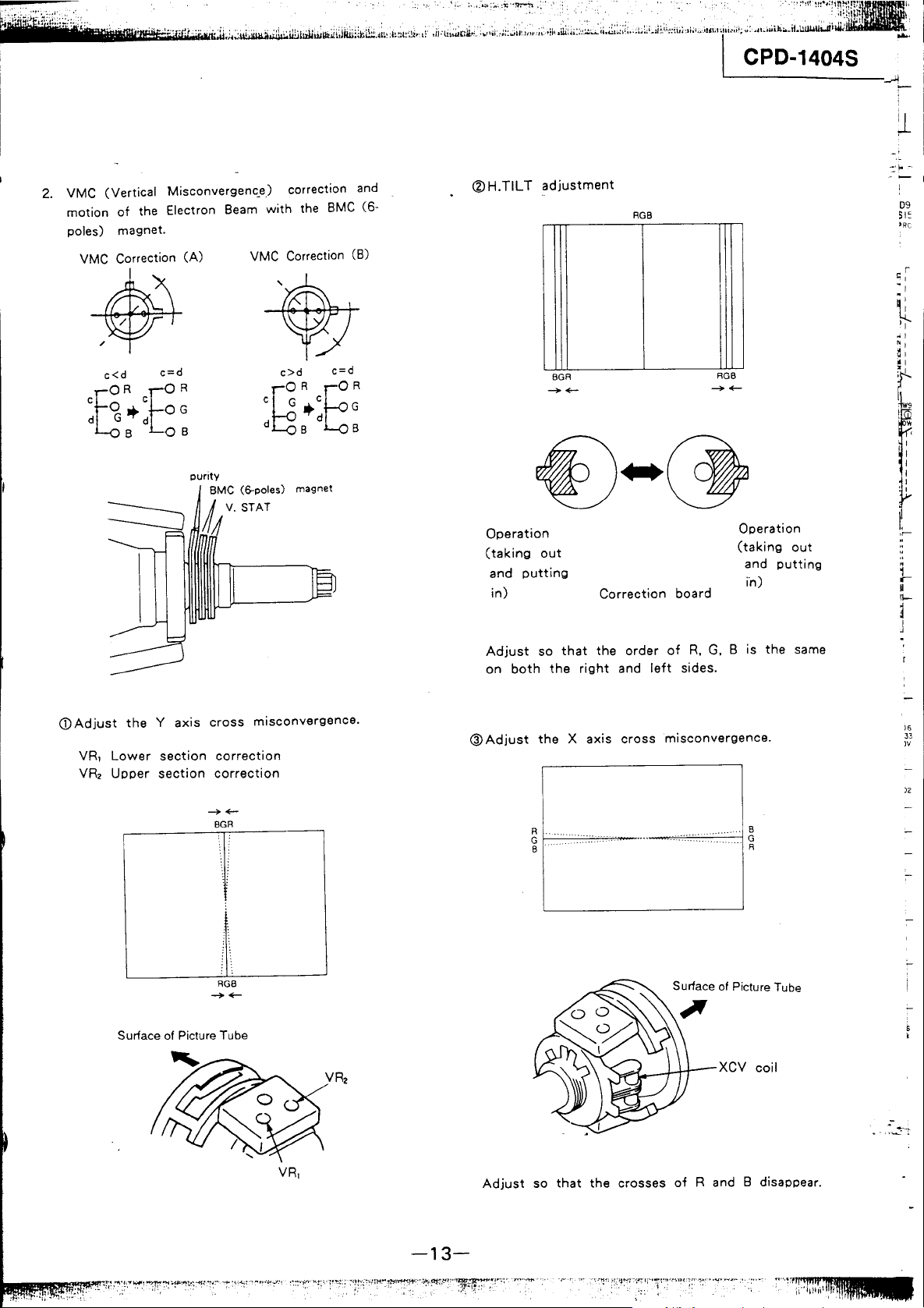
2.
VMC (Vertical Misconvergenc_e) correction
motion
poles) magnet.
of
the Electron Beam
VMC Correction
*+
c<d
cSR
o
*'
d G d
BOB
(A)
c=d
cEO
R
OG
with
VMC Correction (B)
c>d
C G C
g
d B B
the
R
*'
d
and
BMC
(6-
c=d
ER
G
®H.TIL T adjustment
BGR
~+-
Operation
(taking
and
in)
out
putting
Correction
RGB
board
RGB
~+-
Operation
(taking
and
putting
in)
out
09
51:
'RC
CD
Adjust
the Y axis
VR,
VRz
Lower
Upper
section
section
Surface of Picture Tube
cross
misconvergence.
correction
correction
-+-
BGR
RGB
-+-
Adjust
on
both
@Adjust
so
that
the
the
right
the X axis
order
of
R.
G,
and
left
sides.
cross
misconvergence.
Surface of Picture Tube
""..{...._-H-j--XCV
B is
the
coil
same
)6
33
IV
l2
-13-
Adjust
so
that
the
crosses
of
Rand
B disappear.
::;, "
....
'
..
CPD-1404S
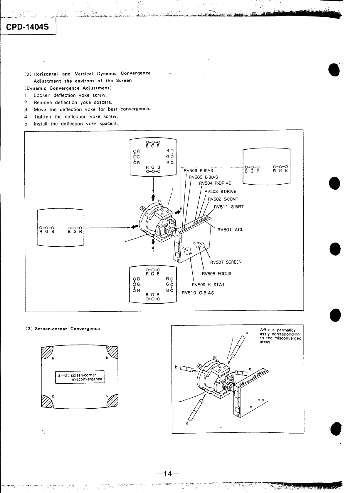
(2)
Horizontal
Adjustment
(Dynamic
1.
Loosen
2. Remove deflection yoke
3. Move
4.
Tighten
Install
5.
and
Vertical
the
environs
Convergence
deflection yoke screw.
the
deflection yoke for
the
the
deflection yoke
Adjustment)
spacers.
deflection yoke screw.
-Dynamic
of
the
best
spacers.
Convergenca
Screen
convergence.
0-0-0
B G R
0-0-<:>
R G B
(3)
Screen-corner
0-0-0
f--------
B G R
Convergence
R G B
0-0-0
0-0-0
R G B
~!
B G R
0-0-0
~~
r----------~
RV506
R-BIAS
B-BIAS
RV505
RVS01
RVS09
H.
STAT
RVS10 G-BIAS
ACL
0-0-0
B G R
Affix
a
ass'y corresponding
to
areas.
0-0-<:5
R G B
a permalloy
the misconverged
•
•
•
a - d : screen-corner
misconvergence
if
o 0
o
·e·
-14-
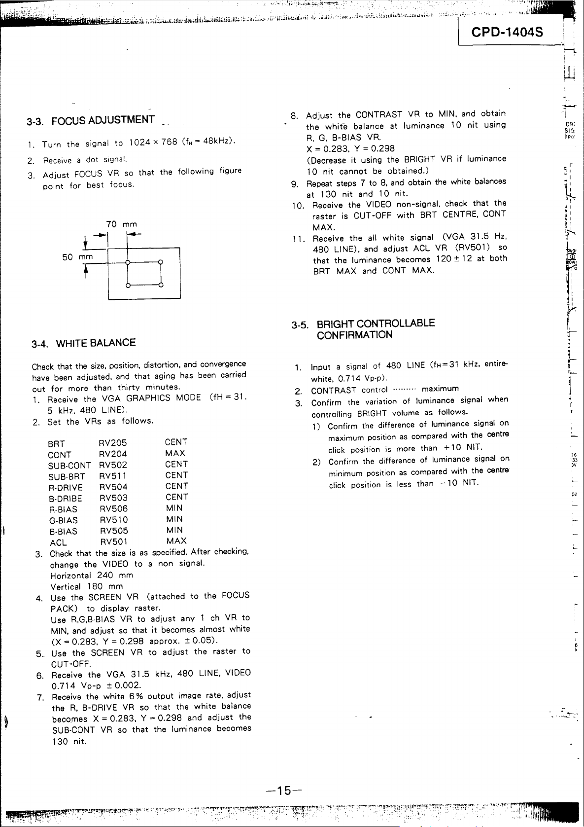
3-3. FOCUS ADJUSTMENT
1.
Turn
2.
3.
Receive
Adjust
point
50
the signal
a dot signal.
FOCUS
for
Ur---+---
mm
-'----+----t
best
to
VR
focus.
70
so
mm
1024 x 768
that
the
(fH =
48kHz).
following
figure
8.
Adjust
the
R.
X =
(Decrease
10
9. Repeat steps 7
at
10. Receive the VIDEO non-signal. check
1 1. Receive
the CONTRAST VR
white
balance at luminance
G,
B-BIAS VR.
0.283.
nit
130
raster
MAX.
480
that
BRT
Y =
it
using the BRIGHT VR
cannot
nit
and
is CUT -OFF
the
LINE), and
the
luminance becomes
MAX
and
0.298
be
to
8.
10
all
white
adjust
CaNT
to
MIN. and obtain
10
if
obtained.)
and
obtain the white balances
nit.
with
BRT CENTRE,
signal
MAX.
ACL VR
120
(VGA
(RV501)
± 12 at both
,
••
!II.I~t
"''''''''_''1
CPD-1404S
nit
using
luminance
that
the
CaNT
31.5
Hz,
so
1
'\
,,'
h
, '
,
~
i
L
1
1
D9;
S15:
PRO'
r'
~
I
- 1
~
• I
"I
~
I
f
3-4. WHITE BALANCE
Check
that the
have been adjusted. and
out
for
1.
Receive
5 kHz,
2. Set
BRT
CaNT
SUB-CaNT
SUB·BRT
R·DRIVE
B-DRIBE
R-BIAS
G-BIAS
B·BIAS
ACL
3.
Check
change
Horizontal
Vertical
4. Use the
PACK)
Use R.G,B-BIAS VR
MIN.
ex
5..
Use the SCREEN VR
CUT-OFF.
6. Receive
0.714
7. Receive the white 6 %
the
becO,mes
SUB-CaNT VR so
130
size.
more
than
the
VGA
480
LINE).
the
VRs
as
RV205
RV204
RV502
RV511
RV504
RV503
RV506
RV510
RV505
RV501
that the size
the
VIDEO
240
180
SCREEN
to
display
and
adjust so
=
0.283,
R.
Y =
the
VGA
Vp-p ± 0.002.
B-DRIVE VR so
X =
nit.
position. distortion,
thirty
GRAPHICS MODE
follows.
is
mm
mm
VR
0.298
0.283.
and
convergence
that
aging has been carried
minutes.
CENT
MAX
CENT
CENT
CENT
CENT
MIN
MIN
MIN
MAX
as
specified.
to
a non signal.
(attached
raster.
to
adjust
that
it
becomes almost white
approx. ±
to
31.5
kHz,
output
that
Y =
0.298
that
the luminance becomes
After
to
any 1 ch VR
0.05).
adjust
the
480
LINE. VIDEO
image rate. adjust
the
white
and
(fH
checking,
the
FOCUS
raster
balance
adjust
= 31.
the
to
to
3-5. BRIGHT CONTROLLABLE
CONFIRMATION
1. Input a signal of 480 LINE
white. 0.714 Vp-p).
2.
CONTRAST control
3. Confirm the variation
controlling
1) Confirm the difference
2)
BRIGHT
maximum position
click position
Confirm the difference of luminance signal on
minimum position
click position
..
....... maximum
of
luminance signal when
volume
is
is
as
of
as
compared with the centre
more than + 1 0 NIT.
as
compared with the centre
less than
(fH=31
luminance signal on
follows.
-10
kHz. entire-
NIT,
i
,r-
o
"
1
r
II-
)6
133
)V
D2
-15-
r_C_P_~_~1_4_04_:'S_"
-.II
SECTION 4
SAFETY RELATED ADJUSTMENT
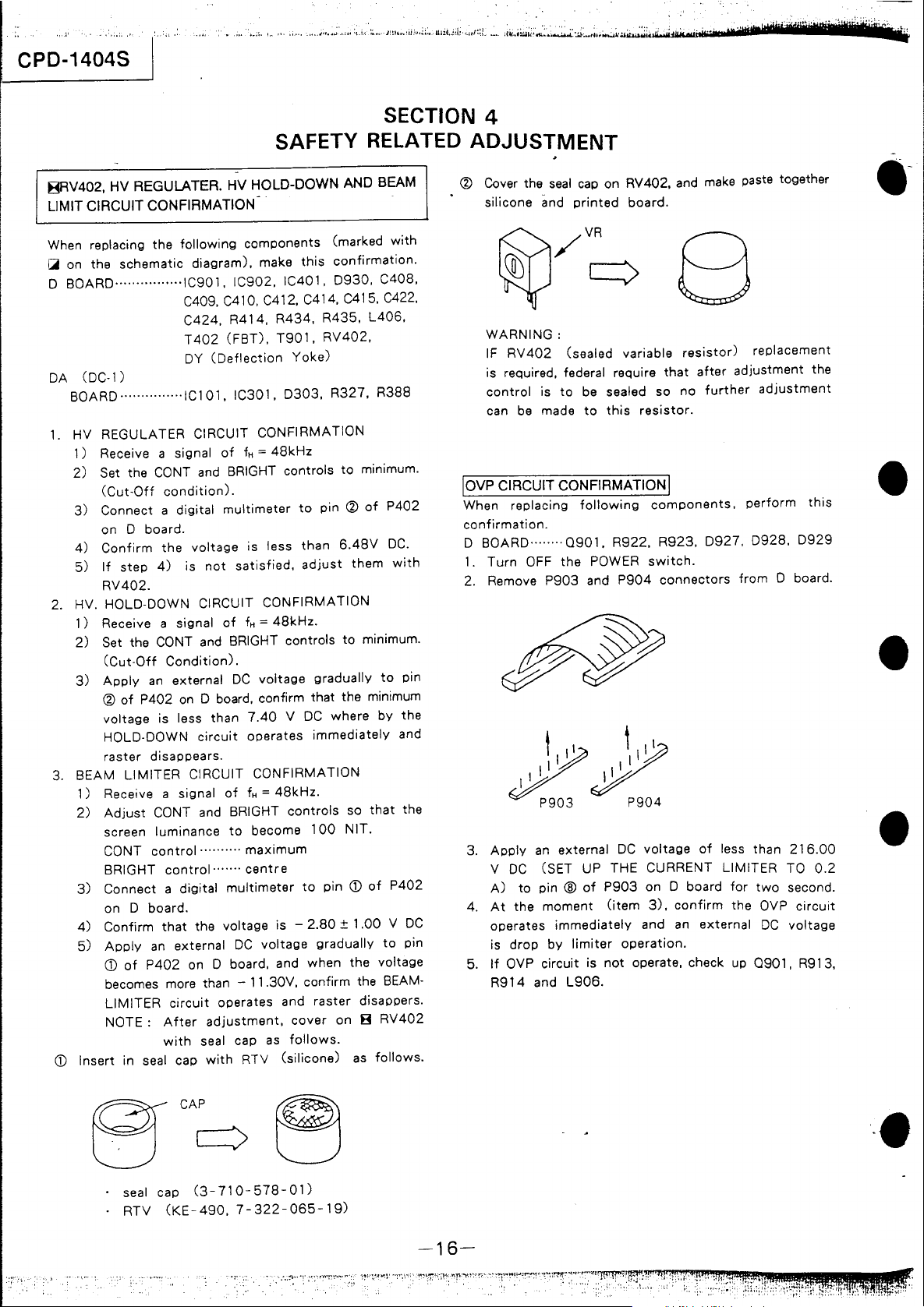
(g)
8RV402, HV REGULATER. HV HOLD-DOWN AND BEAM
LIMIT CIRCUIT CONFIRMATION
Cover the
silicone
seal
and
cap
on RV402, and make paste together
printed
board.
.-
When replacing
~
on
the
o
BOARO················IC901.
DA
(OC·l)
BOARO ............ ·
1.
HV REGULATER CIRCUIT
1) Receive a signal
2)
Set the CONT and BRIGHT controls
(Cut·Off
3)
Connect a digital
on
4)
Confirm
5)
If
RV402.
2. HV.
3. BEAM
HOL~-~OWN
1)
Receive a signal
2)
Set the CONT and BRIGHT controls
(Cut·Off
3)
Apply
(g)
voltage
HOLO·OOWN
raster
1) Receive a signal
2)
Adjust
screen
CONT
BRIGHT
3)
Connect a digital
on 0 board.
4)
Confirm
5)
Apply
CD
becomes more than - 11.30V, confirm the BEAM·
LIMITER
NOTE:
CD
Insert in seal cap
the
following
schematic
C409, C410, C412, C414, C415. C422.
C424,
T402
DY
..
IC101, IC301,
condition).
0 board.
the
step
4)
is
Condition).
an
external
of
P402
on
is less
disappears.
LIMITER
CONT and BRIGHT
luminance
control
control·
that
an
external
of
P402
on 0 board, and
circuit
After
with
components
diagram),
(Deflection
voltage
not
CIRCUIT
0 board, confirm
than
circuit
CIRCUIT CONFIRMATION
..........
the voltage is -
adjustment,
seal cap
with
make
IC902.
R41
(FBT).
of
multimeter
satisfied,
of
DC
of
to
......
multimeter
DC
operates and
IC401,
4,
R434, R435,
T901,
0303,
CONFIRMATION
fH = 48kHz
is less
CONFIRMATION
fH = 48kHz.
voltage
7.40 V DC
operates
fH = 48kHz.
become
maximum
centre
voltage
as
RTV
(silicone)
this
RV402,
Yoke)
to
pin
than
adjust
gradually
that
immediately
controls
100
to
pin
2.80
gradually
when
raster
cover
follows.
(marked
confirmation.
0930,
R327,
to
(g)
6.48V
them
to
the minimum
where
so
NIT.
CD
± 1
the
on 8
with
C408,
L406,
R388
minimum.
of
P402
~C.
with
minimum.
to
pin
by
the
and
that
the
of
P402
.00 V DC
to
voltage
disappers.
RV402
as
follows.
pin
WARNING:
IF
RV
402
(sealed variable
is required,
control
can
loVp
CIRCUIT CONFIRMATION I
When replacing
confirmation.
D BOARD .... ·
1.
Turn
2. Remove
3.
Apply
V
DC
A)
At
4.
5.
the
operates
is
drop
If
OVP circuit is
R914
federal require
is
to
be sealed so
be
made
to
following
.. · 0901,
OFF
the
POWER
P903
and
an
external
(SET UP THE CURRENT LIMITER TO
to
pin ®
of
moment
immediately
by
limiter
and
L906.
8
that
this
resistor.
components,
R922,
R923,
switch.
P904
connectors
DC
voltage
P903
on 0 board
(item
3),
confirm
and an
operation.
not
operate, check up
resistor)
after
no
further
0927. 0928.
of
less than
external
replacement
adjustment
adjustment
perform
from
0 board.
for
two
the
OVP
DC
0901,
the
this
0929
216.00
0.2
second.
circuit
voltage
R913,
•
•
•
seal cap
RTV
(KE-490,
CAP
-.
(3-710-578-01)
7-322-065-19)
-16-
~
iiii1
__
"';.'
....
J
'~a:-
t ...
~"iiIii'~'
!iOii'
~~
:;
I.!U' .•• r
.... " ....
\ ..•
i:
...
""
..•
..••
~T.'''''''''
~
~,
.1
i ~ :.
,...;
~;
,I.:
",'
I,. : .........
;!.
..
{.
::!'"
..
""
IU
•.
1
••
'"
.... : ... : •.
1: : II
Ii.
I'
""
.,'
' : ' , . ! I : • . .
,.
";!Jil;!ii~ii~m~
. CPD-1404S
1
-
-
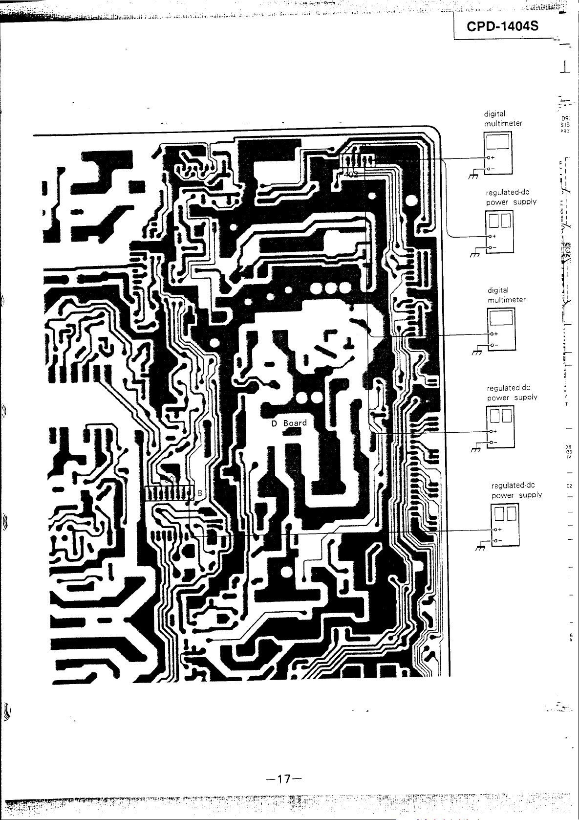
digital
multi meter
09:
515
PRO
regulated-de
power supply
DO
digital
~I
b -
regulated·de
power supply
DO
,)6
'33
)v
·-
 Loading...