

Page 1
2-342-683-12(1)
Home Theatre
System
Operating Instructions
HTR-6600
HTR-6100
©2004 Sony Corporation
Page 2
WARNING
To prevent fire or shock hazard, do not
expose the unit to rain or moisture.
To prevent fire, do not cover the ventilation of the
apparatus with newspapers, table-cloths, curtains, etc.
And don’t place lighted candles on the apparatus.
To prevent fire or shock hazard, do not place objects
filled with liquids, such as vases, on the apparatus.
Do not install the appliance in a confined space,
such as a bookcase or built-in cabinet.
Don’t throw away batteries with
general house waste; dispose of
them correctly as chemical waste.
About This Manual
• The instructions in this manual are for model
HTR-6600 and HTR-6100. Check your model
number by looking at the lower right corner of the
front panel. In this manual, HTR-6100 is used for
illustration purposes unless stated otherwise.
• The instructions in this manual describe the controls
on the remote. You can also use the controls on the
receiver if they have the same or similar names as
those on the remote. For details on the use of your
remote, see pages 30–33. For details on the use of
your DVD recorder, refer to separate operating
instructions supplied with the DVD recorder.
The HTR-6600 consists of:
• Receiver STR-KSL600
• Speaker system
– Front speakers SS-SLP701
– Center speaker SS-CNP501
– Surround speakers SS-MSP501
– Sub woofer SA-WMSP601
• DVD recorder RDR-GX300
The HTR-6100 consists of:
• Receiver STR-KSL600
• Speaker system
– Front/Surround speakers SS-MSP501
– Center speaker SS-CNP501
– Sub woofer SA-WMSP601
• DVD recorder RDR-GX300
This receiver incorporates Dolby* Digital and Pro
Logic Surround and the DTS** Digital Surround
System.
* Manufactured under license from Dolby
Laboratories.
“Dolby”, “Pro Logic” and the double-D symbol are
trademarks of Dolby Laboratories.
** “DTS” and “DTS Digital Surround” are registered
trademarks of Digital Theater Systems, Inc.
Note for the supplied remote
For RM-U700
The AUX button on the remote is not available
for receiver operation.
GB
2
Page 3

Table of Contents
Getting Started
1: Check how to hookup your
components.......................................4
1a: Connecting components with
digital audio output jacks ...........6
1b: Connecting components with
only analog audio jacks .............. 8
2: Connecting the antennas .....................9
3: Connecting speakers .........................10
4: Connecting the AC power cord ........13
5: Setting up the speakers .....................14
6: Setting up the sub woofer .................15
7: Adjusting the speaker levels and
balance............................................16
— TEST TONE
Amplifier Operation
Selecting the component .......................17
Listening to FM/AM radio....................17
Storing FM stations automatically ........ 18
— AUTOBETICAL
Presetting radio stations........................19
Using the Radio Data System (RDS)....20
About the indications in the display......22
Enjoying Surround Sound
Using only the front speakers and sub
woofer.............................................23
— 2CH STEREO
Enjoying higher fidelity sound..............23
Selecting a sound field..........................24
Other Operations
Using the Sleep Timer .......................... 29
Operations Using the Remote
RM-U700
Before you use your remote.................. 30
Remote button description.................... 30
Changing the factory setting of an
input button .................................... 33
Additional Information
Precautions............................................ 34
Troubleshooting.................................... 35
Specifications........................................ 37
List of button locations and reference
pages............................................... 39
Index ........................................back cover
Advanced Adjustments and
Settings
Customizing sound fields......................26
Adjusting the tone.................................27
Advanced settings.................................28
GB
3
Page 4

Getting Started
1: Check how to hookup your components
Steps 1a through 1b beginning on page 6 describe how to hook up your components to this receiver.
Before you begin, refer to “Connectable components” below for the pages which describe how to
connect each component.
After hooking up all your components, proceed to “2: Connecting the antennas” (page 9).
Connectable components
Component to be connected Page
DVD recorder
With digital audio output
With analog audio output only
TV monitor
With composite video input only 7, 8
Satellite tuner
With digital audio output
With analog audio output only
VCR 8
a)
Model with a DIGITAL OPTICAL OUTPUT or DIGITAL COAXIAL OUTPUT jack, etc.
b)
Model equipped only with AUDIO OUT L/R jacks, etc.
a)
b)
a)
b)
6–7
6–7
6
6
GB
4
Page 5
Required cords
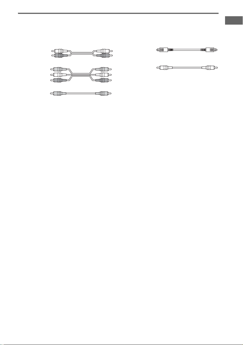
The hookup diagrams on the subsequent pages assume the use of the following optional connection
cords (A to E) (not supplied unless indicated).
A Audio cord
White (L)
Red (R)
B Audio/video cord
Yellow (video)
White (L/audio)
Red (R/audio)
C Video cord
Yellow
Notes
• Turn off the power to all components before making any connections.
• Be sure to make connections firmly to avoid hum and noise.
• When connecting an audio/video cord, be sure to match the color-coded pins to the appropriate jacks on the
components: yellow (video) to yellow; white (left, audio) to white; and red (right, audio) to red.
• When connecting optical digital cords, insert the cord plugs straight in until they click into place.
• Do not bend or tie optical digital cords.
D Optical digital cord
E Coaxial digital cord (supplied)
Orange
Getting Started
GB
5
Page 6
.
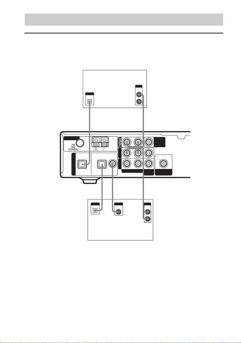
1a: Connecting components with digital audio output jacks
Hooking up a DVD recorder or satellite tuner
For details on the required cords (A–E), see page 5.
1 Connect the audio jacks.
Satellite tuner
OUTPUT
AUDIO
OUTPUT
DIGITAL
OPTICAL
OUT
L
R
ANTENNA
DIGITAL
OPT IN
TV/SAT
D
U
OUTPUT
OPTICAL
AM
OPT IN COAX IN
DVD
*
D
*
OUTPUT
DIGITAL
COAXIAL
A
DVDVIDEO
AUDIO IN
RL
L
R
VIDEO
IN
AE
OUTPUT
AUDIO
OUT
MONITOR
OUT
OUT
SUB
WOOFER
DVD recorder
* Connect to either the COAX IN or OPT IN jack. We recommend making connections to the COAX IN jack.
Tip
All the digital audio jacks are compatible with 32 kHz, 44.1 kHz, 48 kHz and 96 kHz sampling frequencies.
GB
6
Page 7
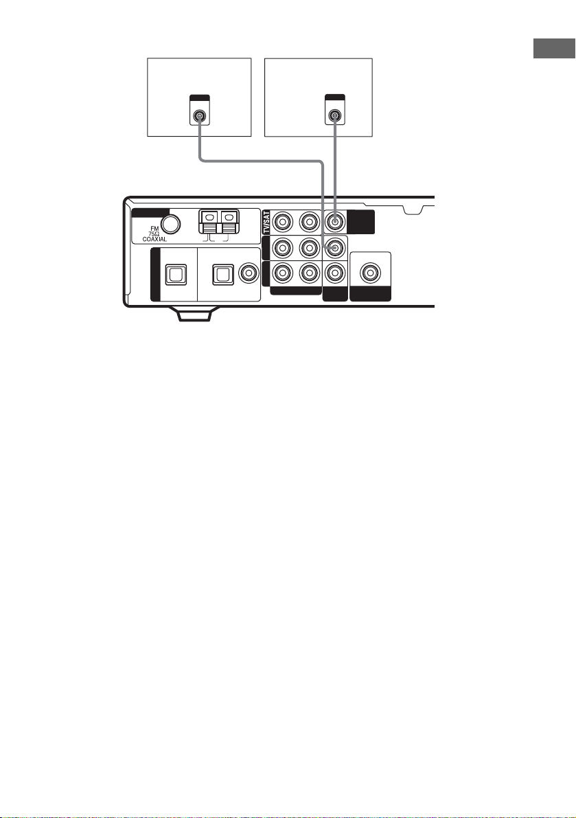
2 Connect the video jacks.
ANTENNA
DIGITAL
DVD recorder
OUTPUT
VIDEO
C
U
OPT IN
TV/SAT
AM
OPT IN COAX IN
DVD
TV monitor
DVDVIDEO
AUDIO IN
RL
INPUT
VIDEO
C
VIDEO
IN
MONITOR
OUT
OUT
SUB
WOOFER
Getting Started
GB
7
Page 8
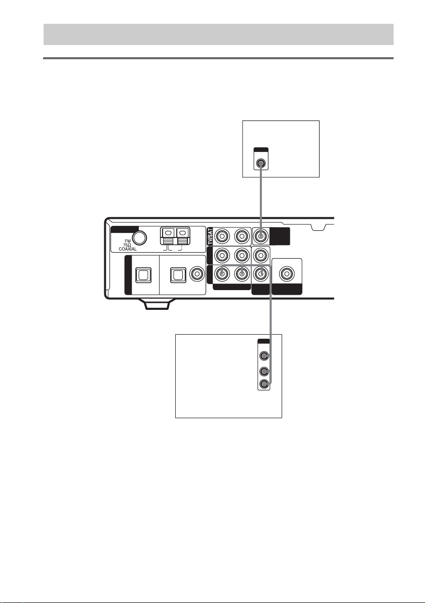
1b: Connecting components with only analog audio jacks
Hooking up video components
If you connect your TV to the MONITOR OUT jack, you can watch the video from the selected input
(page 17). For details on the required cords (A
–E), see page 5.
INPUT
VIDEO
TV monitor
C
ANTENNA
DIGITAL
OPT IN
TV/SAT
U
AM
OPT IN COAX IN
DVD
DVDVIDEO
AUDIO IN
RL
VIDEO
IN
MONITOR
OUT
OUT
SUB
WOOFER
B
OUTPUT
VIDEO
AUDIO
OUT
OUT
L
R
VCR
GB
8
Page 9
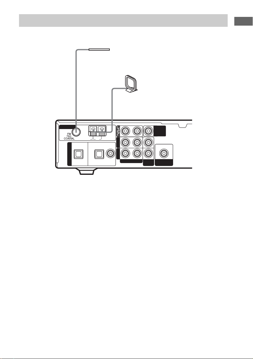
2: Connecting the antennas
Connect the supplied AM loop antenna and FM wire antenna.
FM wire antenna
(supplied)
Getting Started
AM loop antenna
(supplied)
ANTENNA
DIGITAL
OPT IN
TV/SAT
U
AM
OPT IN COAX IN
DVD
DVDVIDEO
AUDIO IN
RL
VIDEO
IN
MONITOR
OUT
OUT
SUB
WOOFER
Notes
• To prevent noise pickup, keep the AM loop antenna away from the receiver and other components.
• Be sure to fully extend the FM wire antenna.
• After connecting the FM wire antenna, keep it as horizontal as possible.
GB
9
Page 10
3: Connecting speakers
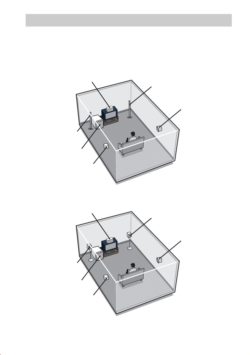
Connect your speakers to the receiver. This receiver allows you to use a 5.1 channel speaker system.
To fully enjoy theater-like multi channel surround sound requires five speakers (two front speakers, a
center speaker, and two surround speakers) and a sub woofer (5.1 channel).
Example of 5.1 channel speaker system configuration
HTR-6600 only
Center speaker
Front speaker (Left)
Sub woofer
Surround speaker (Left)
Front speaker (Right)
Surround speaker (Right)
HTR-6100 only
GB
10
Center speaker
Front speaker (Right)
Surround speaker (Right)
Front speaker (Left)
Sub woofer
Surround speaker (Left)
Page 11

Required cords
A Speaker cords (supplied)
The connector and the colour tube of the speaker
cords are the same colour as the speaker terminal
to be connected.
Colour tube
+
–
B Monaural audio cord (supplied)
Black
Getting Started
INPUT
MONITOR
OUT
OUT
SUB
WOOFER
Subwoofer
B
A
E
Surround speaker
(Right)
e
Front speaker
E
Center speaker
(Right)
Ee
A
FRONT R
CENTER
– + –
– +
SURR R SURR L
A
e
Front speaker
(Left)
Ee
A
FRONT L
+
+ –+ –
A
E
Surround speaker
(Left)
e
Note
Before you connect the speakers, attach the colour labels onto the speakers so that you can identify the speakers to
be connected.
continued
11
GB
Page 12
Tips
• Since the sub woofer doe s not emit highly directional
signals, you can place it wherever you want.
• (Except for the front speaker of HTR-6600) For
greater flexibility in the positioning of the speakers,
use the optional W S-FV11 or WS-FV10D floor stand
(available only in certain countries).
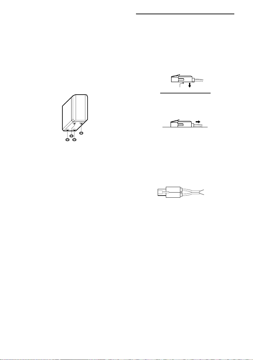
Attaching foot pads
(Except for the front speaker of HTR-6600)
To prevent speaker vibration or movement,
attach the supplied foot pads to the speaker as
shown in the illustration below.
Note
Be sure to attach the supplied foot pads to the sub
woofer as well.
To change the speaker cord
If you want to change the speaker cord, you can
detach the supplied speaker cord from the
connector.
1 Press the connector onto a flat surface.
Make sure that the catcher is facing the flat
surface.
catcher
2 Pull the speaker cord from the
connector.
3 Twist the stripped ends of the speaker
cord you want about 10 mm and insert
the speaker cord into the connector.
Make sure that the speaker cord is inserted
according to its polarity : + to + and – to –.
Otherwise the sound will be distorted and
will lack bass.
12
+
–
(+)
(–)
4 Remove the connector from the flat
surface.
Note
To avoid the speaker cord from coming off the speaker
connector
– do not use a smaller-size speaker cord. We
recommend that you use the AWG#18 to AWG#24
speaker cords.
– use the same speaker cord size for all the speaker
connectors.
– twist the stripped ends of the speaker cords.
– insert the speaker cord completely into the speaker
connector.
GB
Page 13
4: Connecting the AC power cord
Connecting the AC power
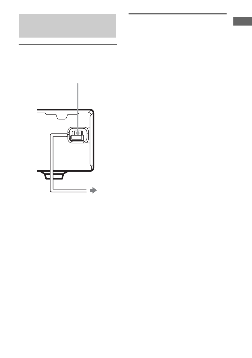
cord
Connect the AC power cord to a wall outlet.
AC power cord
Performing initial setup
operations
Before using the receiver for the first time,
initialize the receiver by performing the
following procedure.
This procedure can also be used to return
settings you have made to their factory defaults.
Use the buttons on the receiver for the operation.
1 Press ?/1 to turn off the receiver.
2 Hold down ?/1 for 5 seconds.
“INITIAL” appears in the display.
The following are reset to their factory
settings.
• All settings in the SET UP, LEVEL and
TONE menus.
• The sound field memorized for each
input and preset station.
• All sound field parameters.
• All preset stations.
• MASTER VOLUME is set to “VOL
MIN”.
Getting Started
To a wall outlet
13
GB
Page 14
5: Setting up the speakers
You can use the SET UP menu to set the
distance and location of the speakers connected
to this receiver.
1 Press ?/1 to turn on the receiver.
2 Press MAIN MENU repeatedly to select
“SET UP”.
3 Press or repeatedly to select the
parameter you want to adjust.
For details, see “Speaker setup parameters”
below.
Note
Some speaker setup items may appear dimmed in
the display. This means that they have been
adjusted automatically due to other speaker
settings or may not be adjustable.
4 Press or repeatedly to select the
setting you want.
The setting is entered automatically.
5 Repeat steps 3 and 4 until you have set
all of the items that follow.
Speaker setup parameters
The initial setting is underlined.
L
R
x DIST. X.X m
(Front speaker distance)
Initial setting: 3.0 m
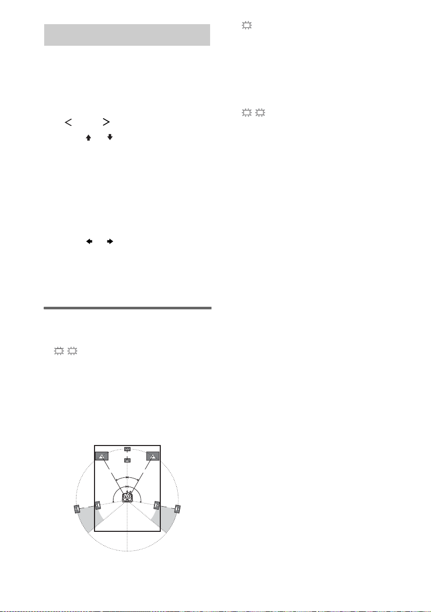
Lets you set the distance from your listening position
to the front speakers (A). You can adjust from 1.0
meter to 7.0 meters in 0.1 meter steps.
If both front speakers are not placed an equal distance
from your listening position, set the distance to the
closest speaker.
B
A
A
30˚30˚
100˚-120˚100˚-120˚
C
x DIST. X.X m
(Center speaker distance)
Initial setting: 3.0 m
Lets you set the distance from your listening position
to the center speaker. Center speaker distance should
be set from a distance equal to the front speaker
distance (A) to a distance 1.5 meters closer to your
listening position (B).
SR
SL
x DIST. X.X m
(Surround speaker distance)
Initial setting: 3.0 m
Lets you set the distance from your listening position
to the surround speakers. Surround speaker distance
should be set from a distance equal to the front speaker
distance (A) to a distance 4.5 meters closer to your
listening position (C).
If both surround speakers are not placed an equal
distance from your listening position, set the distance
to the closest speaker.
Tip
The receiver lets you to input the speaker position in
terms of distance. However, it is not possible to set the
center speaker further than the front speakers. Also, the
center speaker cannot be set more than 1.5 meters
closer than the front speakers.
Likewise, the surround speakers cannot be set further
away from the listening position than the front
speakers. And they can be no more than 4.5 meters
closer.
This is because incorrect speaker placement is not
conducive to the enjoyment of surround sound.
Please note that, setting the speaker distance closer than
the actual location of the speakers will cause a delay in
the output of the sound from that speaker. In other
words, the speaker will sound like it is further away.
For example, setting the center speaker distance 1–2
meters closer than the actual speaker position will
create a fairly realistic sensation of being “inside” the
screen. If you cannot obtain a satisfactory surround
effect because the surround speakers are too close,
setting the surround speaker distance closer (shorter)
than the actual distance will create a larger sound stage.
Adjusting these parameter while listening to the sound
often results in much better surround sound. Give it a
try!
14
CC
GB
Page 15
SR
SL
x PL. XXXX
(Surround speaker placement)
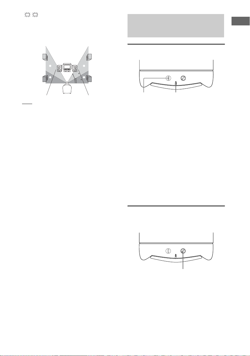
Lets you specify the height of your surround speakers
for proper implementation of the surround effects of
the Cinema Studio EX modes (page 24).
6: Setting up the sub
Getting Started
woofer
Listening to the sub woofer
B
A
B
60
A
30
•LOW
Select if the height of your surround speakers
corresponds to section A.
•HIGH
Select if the height of your surround speakers
corresponds to section B.
POWER
LEVEL
MIN MAX
POWER
POWER indicator
Before playing the program source, set the
volume to minimum on the receiver.
1 Turn on the receiver.
2 Press input buttons (e.g., DVD) to
select the program source (e.g., DVD
recorder).
Tip
You can also use INPUT SELECTOR on the
receiver to select the program source.
3 Press POWER on the sub woofer.
The POWER indicator on the sub woofer
lights up.
4 Play the program source.
Adjusting the level
Slight adjustments to the system can enhance
your sound enjoyment.
POWER
LEVEL
MIN MAX
LEVEL
Turn LEVEL to adjust the volume.
Set the volume level to best suit your preference
according to the program source.
Note
Do not set the volume of the sub woofer to maximum.
Extraneous noise may be heard.
15
GB
Page 16

7: Adjusting the speaker levels and balance
— TEST TONE
Adjust the speaker levels and balance while
listening to the test tone from your listening
position.
Tip
The receiver employs a test tone with a frequency
centered at 800 Hz.
1 Press ?/1 to turn on the receiver.
2 Press TEST TONE.
“T. TONE” appears in the display and the
test tone is output from each speaker in
sequence.
Front (left) t Center t Front (right) t
Surround (right) t Surround (left) t
Sub woofer
3 Adjust the speaker levels and balance
using the LEVEL menu so that the level
of the test tone sounds the same from
each speaker.
For details on the LEVEL menu settings,
see page 26.
Tips
• To adjust the level of all speakers at the same
time, press MASTER VOL +/– on the remote or
turn MASTER VOLUME on the receiver.
• The adjusted value is shown in the display
during adjustment.
4 Press TEST TONE again after
adjustment.
The test tone turns off.
16
GB
Page 17

Amplifier Operation
Selecting the component
1 Press INPUT SELECTOR on the
receiver to select the component you
want to use.
To select the Light up
VCR VIDEO
DVD recorder DVD
Satellite tuner TV/SAT
Built-in tuner (FM/AM) TUNER
2 Turn on the component and start
playback.
Note
If you select the VCR or DVD recorder, set the
TV’s video input to match the component you
selected.
3 Turn MASTER VOLUME on the receiver
to adjust the volume.
Note
To avoid damaging your speakers, make sure that
you turn down the volume before you turn off the
receiver.
To mute the sound
Press MUTING.
The muting function will be canceled when you
do the following.
• Press MUTING again.
• Turn the power off.
• Increase the volume.
Listening to FM/AM radio
You can listen to FM and AM broadcasts
through the built-in tuner. Before operation,
make sure you have connected the FM and AM
antennas to the receiver (see page 9).
Tip
The tuning scale is:
FM: 50 kHz
AM: 9 kHz
Automatic tuning
If you do not know the frequency of the station
you want, you can let the receiver scan all
available stations in your area.
1 Press TUNER repeatedly to select the
FM or AM band.
The last received station is tuned in.
Tip
You can also use INPUT SELECTOR on the
receiver.
2 Press TUNING + or TUNING –.
Press TUNING + to scan from low to high;
press TUNING – to scan from high to low.
The receiver stops scanning whenever a
station is received.
Tip
If “STEREO” flashes in the display and the FM stereo
reception is poor, press FM MODE to change to
monaural (MONO). You will not be able to enjoy the
stereo effect, but the sound will be less distorted. To
return to stereo mode, press FM MODE again.
Amplifier Operation
continued
17
GB
Page 18

Direct tuning
You can enter the frequency of the station you
want directly.
1 Press TUNER repeatedly to select the
FM or AM band.
The last received station is tuned in.
2 Press D.TUNING.
3 Press the numeric buttons to enter the
frequency.
Example 1: FM 102.50 MHz
Press 1 b 0 b 2 b 5 b 0
Example 2: AM 1,350 kHz
Press 1 b 3 b 5 b 0
If you have tuned in an AM station, adjust
the direction of the AM loop antenna for
optimum reception.
If you cannot tune in a station
and the entered numbers flash
Make sure you have entered the right frequency.
If not, repeat steps 2 and 3. If the entered
numbers still flash, the frequency is not used in
your area.
Storing FM stations automatically
— AUTOBETICAL
This function lets you store up to 30 FM and FM
RDS stations in alphabetical order without
redundancy. Additionally, it only stores the
stations with the clearest signals.
If you want to store FM or AM stations one by
one, see “Presetting radio stations”.
Use the buttons on the receiver for the operation.
1 Press ?/1 to turn off the receiver.
2 Hold down INPUT SELECTOR and
press ?/1 to turn the receiver back on.
“AUTO-BETICAL SELECT” appears in
the display and the receiver scans and stores
all the FM and FM RDS stations in the
broadcast area.
For RDS stations, the tuner first checks for
stations broadcasting the same program,
then stores only the one with the clearest
signal. The selected RDS stations are sorted
alphabetically by their Program Service
name, then assigned a 2-character preset
code. For more details on RDS, see
page 20.
Regular FM stations are assigned 2character preset codes and stored after the
RDS station.
When done, “FINISH” appears in the
display momentarily and the receiver
returns to the normal operation.
Notes
• Do not press any button on the receiver or supplied
remote during autobetical operation, except ?/1.
• If you move to another area, repeat this procedure to
store stations in your new area.
• For details on tuning the stored stations, see “Tuning
to preset stations”.
• If you move the antenna after storing stations with
this procedure, the stored settings may no longer be
valid. If this happens, repeat this procedure to store
the stations again.
18
GB
Page 19
Presetting radio stations
You can preset up to 30 FM or AM stations.
Then you can easily tune in the stations you
often listen to.
Presetting radio stations
1 Press TUNER repeatedly to select the
FM or AM band.
The last received station is tuned in.
2 Tune in the station that you want to
preset using Automatic Tuning
(page 17) or Direct Tuning (page 18).
3 Press MEMORY.
“MEMORY” appears in the display for a
few seconds. Do steps 4 to 5 before the
display goes out.
4 Press PRESET/CH/D.SKIP + or
PRESET/CH/D.SKIP – repeatedly to
select a preset station number.
Each time you press the button, you can
select the preset station number as follows:
tA1yA2y...yA0yB1yB2y...yB0T
tC0y...yC2yC1T
If “MEMORY” goes out before you select
the preset station number, start again from
step 3.
Tips
• You can also use PRESET TUNING + or
PRESET TUNING – on the receiver.
• You can also press SHIFT repeatedly to select a
memory page (A, B or C) and then press the
numeric buttons to select a preset number.
5 Press MEMORY again.
The station is stored to the selected preset
number.
If “MEMORY” goes out before you press
MEMORY, start again from step 3.
6 Repeat steps 2 to 5 to preset another
station.
Tuning to preset stations
1 Press TUNER repeatedly to select the
FM or AM band.
The last received station is tuned in.
2 Press PRESET/CH/D.SKIP + or
PRESET/CH/D.SKIP – repeatedly to
select the preset station you want.
Each time you press the button, you can
select the preset station as follows:
tA1yA2y...yA0yB1yB2y...yB0T
tC0y...yC2yC1T
Using the receiver
1 Press INPUT SELECTOR repeatedly to
select FM or AM.
2 Press PRESET TUNING – or PRESET
TUNING + repeatedly to select the preset
station you want.
To select the preset station
directly
Press the numeric buttons.
The preset station of the selected number in the
current memory page is tuned in. Press SHIFT
repeatedly on the remote to change the memory
page.
Amplifier Operation
19
GB
Page 20

Using the Radio Data System (RDS)
This receiver also allows you to use RDS (Radio
Data System), which enables radio stations to
send additional information along with the
regular program signal. You can also display
RDS information.
Notes
• RDS is operable only for FM stations.
• Not all FM stati ons provide RDS service, nor do the y
provide the same types of services. If you are not
familiar with the RDS services in your area, check
with your local radio stations for details.
Receiving RDS broadcasts
Simply select a station on the FM band
using Automatic tuning (page 17), Direct
tuning (page 18), or preset tuning
(page 19).
When you tune in a station that provides RDS
services, the RDS indicator lights up and the
program service name appears in the display.
Note
RDS may not work properly if the station you tuned to
is not transmitting the RDS signal properly or if the
signal strength is weak.
Displaying RDS information
While receiving an RDS station, press
DISPLAY repeatedly.
Each time you press the button, RDS
information on the display changes cyclically as
follows:
Program Service name t Frequency t
Program Type indication
indication
b)
t Current Time indication (in 24hour system) t Sound field currently applied
t Volume level
a)
Type of program being broadcast (see page 20).
b)
Text messages sent by the RDS station.
a)
t Radio Text
Notes
• If there is an emerge ncy announcement by government
authorities, “ALARM” flashes in the display.
• When the message consists of 9 characters or more,
the message scrolls across the display.
• If a station does not provide a particular RDS service ,
“NO XXXX” (such as “NO TEXT”) appears in the
display.
Description of program types
Program type
indication
NEWS News programs
AFFAIRS Topical programs that expand on
INFO Programs offering information on
SPORT Sports programs
EDUCATE Educational programs, such as
DRAMA Radio plays and serials
CULTURE Programs about national or
SCIENCE Programs about the natural
VARIED Other types of programs such as
POP M Popular music programs
ROCK M Rock music programs
EASY M Easy Listening
LIGHT M Instrumental, vocal, and choral
CLASSICS Performances of major orchestras,
OTHER M Music that does not fit into any
WEATHER Weather information
FINANCE Stock market reports and trading,
CHILDREN Programs for children
SOCIAL Programs about people and the
RELIGION Programs of religious content
Description
current news
a wide spectrum of subjects,
including consumer affairs and
medical advice
“how-to” and advice programs
regional culture, such as language
and social concerns
sciences and technology
celebrity interviews, panel games,
and comedy
music
chamber music, opera, etc.
categories above, such as Rhythm
& Blues and Reggae
etc.
things that affect them
20
GB
Page 21

Program type
indication
Description
PHONE IN Programs where members of the
public express their views by
phone or in a public forum
TRAVEL Programs about travel. Not for
announcements that are loc ated by
TP/TA
LEISURE Programs on recreational
activities such as gardening,
fishing, cooking, etc.
JAZZ Jazz programs
COUNTRY Country music programs
NATION M Programs featuring the popular
music of the country or region
OLDIES Programs featuring oldies music
FOLK M Folk music programs
DOCUMENT Investigative features
NONE Any programs not defined above
Amplifier Operation
21
GB
Page 22
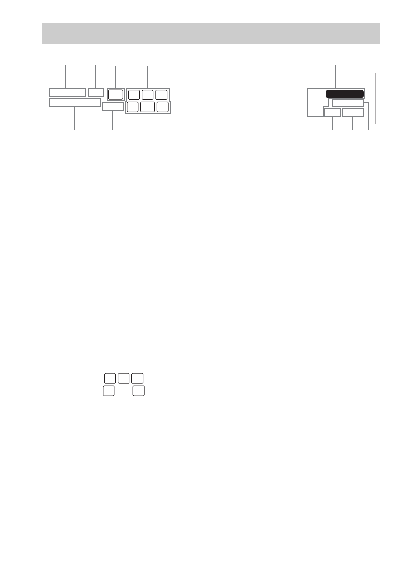
About the indications in the display
21435
DIGITAL
;
PRO LOGIC II
;
DTS
SW
L F E
L C R
SL SSR
9q;
A ; DIGITAL: Lights up when the receiver is
decoding signals recorded in the Dolby Digital
format.
B DTS: Lights up when DTS signals are input.
C SW: Lights up when the audio signal is output
from the SUB WOOFER jack.
D Playback channel indicators: The letters
(L, C, R, etc.) indicate the channels being
played back. The boxes around the letters vary
to show how the receiver downmixes the
source sound.
L (Front Left), R (Front Right), C (Center
(monaural)), SL (Surround Left), SR
(Surround Right), S (Surround (monaural or
the surround components obtained by Pro
Logic processing))
Example:
Recording format (Front /Surround): 3/2
Sound Field: A.F.D. AUTO
ST
MEMORY
D.RANGEMONO
RDS OPT COAX
678
H OPT: Lights up when the source signal is a
digital signal being input through the OPT
terminal.
I LFE: Lights up when the disc being played
back contains the LFE (Low Frequency
Effect) channel and the LFE channel signal is
actually being reproduced.
J ; PRO LOGIC II: “; PRO LOGIC” lights
up when the receiver applies Pro Logic
processing to 2 channel signals in order to
output the center and surround channel
signals. “; PRO LOGIC II” lights up when
the Pro Logic II Movie/Music decoder is
activated.
Note
Dolby Pro Logic and Dolby Pro Logic II
decoding do not function for DTS format signals.
L C R
SL SR
E Tuner indicators: Lights up when using the
receiver to tune in radio stations, etc. See
pages 17–21 for tuner operations.
F D.RANGE: Lights up when dynamic range
compression is activated (page 26).
G COAX: Lights up when the source signal is a
digital signal being input through the COAX
terminal.
GB
22
Page 23

Enjoying Surround Sound
Using only the front
Enjoying higher fidelity sound
speakers and sub woofer
— 2CH STEREO
In this mode, the receiver outputs the sound
from the front left/right speakers and sub woofer
only.
When multi channel surround formats are input,
the signals are downmixed to 2 channel with
bass frequencies being output from the sub
woofer.
When standard 2 channel stereo sources are
input, the receiver’s bass redirection circuitry
will be activated. The front channel bass
frequencies will be output from the sub woofer.
Press SOUND FIELD + or SOUND FIELD –
repeatedly to select “2CH ST.”.
The receiver switches to the 2CH STEREO
mode.
Decoding the input audio
signal automatically (AUTO
FORMAT DIRECT)
In this mode, the receiver automatically detects
the type of audio signal being input (Dolby
Digital, DTS, standard 2 channel stereo, etc.)
and performs the proper decoding if necessary.
This mode presents the sound as it was recorded/
encoded, without adding any surround effects.
However, if there are no low frequency signals
(Dolby Digital LFE, etc.) it will generate a low
frequency signal for output to the sub woofer.
Press A.F.D.
“A.F.D. AUTO” appears in the display.
The receiver automatically detects the type of
audio signal being input and performs the proper
decoding if necessary.
Enjoying Surround Sound
continued
23
GB
Page 24

Enjoying stereo sound in multi
channel (2 channel decoding
mode)
This mode lets you specify the type of decoding
for 2 channel audio sources. This receiver can
reproduce 2 channel sound in 5 channels
through Dolby Pro Logic II or 4 channels
through Dolby Pro Logic.
Press ; PL/PLII repeatedly to select the 2
channel decoding mode.
The selected type of decoding appears in the
display.
x DOLBY PL (PRO LOGIC)
Performs Dolby Pro Logic decoding. The source
recorded in 2 channel is decoded into 4.1 channels.
x PLII MOV (PRO LOGIC II MOVIE)
Performs Dolby Pro Logic II Movie mode decoding.
This setting is ideal for movies encoded in Dolby
Surround. In addition, this mode can reproduce sound
in 5.1 channel when watching videos of overdubbed or
old movies.
x PLII MUS (PRO LOGIC II MUSIC)
Performs Dolby Pro Logic II Music mode decoding.
This setting is ideal for normal stereo sources such as
CDs.
Tip
You can also use ; PLII on the receiver to select
“DOLBY PL”, “PLII MOV” or “PLII MUS”.
Note
Dolby Pro Logic and Dolby Pro Logic II decoding do
not function for DTS format signals.
Selecting a sound field
You can take advantage of surround sound
simply by selecting one of the receiver’s preprogrammed sound fields. They bring the
exciting and powerful sound of movie theaters
and concert halls into your home.
Selecting a sound field for
movies
Press SOUND FIELD + or SOUND FIELD –
repeatedly to select the sound field you
want.
The selected sound field appears in the display.
Sound field Display
CINEMA STUDIO EX A DCS C.ST.EX A
CINEMA STUDIO EX B DCS C.ST.EX B
CINEMA STUDIO EX C DCS C.ST.EX C
About DCS (Digital Cinema
Sound)
Sound fields with DCS marks use DCS
technology.
DCS is the concept name of the surround
technology for home theater developed by Sony.
DCS uses the DSP (Digital Signal Processor)
technology to reproduce the sound
characteristics of an actual cinema cutting studio
in Hollywood.
When played at home, DCS will create a
powerful theater effect that mimics the artistic
combination of sound and action as envisioned
by the movie director.
x C.ST.EX A (CINEMA STUDIO EX A) DCS
Reproduces the sound characteristics of the Sony
Pictures Entertainment “Cary Grant Theater” cinema
production studio. This is a standard mode, great for
watching most any type of movies.
x C.ST.EX B (CINEMA STUDIO EX B) DCS
Reproduces the sound characteristics of the Sony
Pictures Entertainment “Kim Novak Theater” cinema
production studio. This mode is ideal for watching
science-fiction or action movies with lots of sound
effects.
24
GB
Page 25
x C.ST.EX C (CINEMA STUDIO EX C) DCS
Reproduces the sound characteristics of the Sony
Pictures Entertainment scoring stage. This mode is
ideal for watching musicals or films where orchestra
music is featured in the soundtrack.
About CINEMA STUDIO EX modes
CINEMA STUDIO EX modes are suitable for
watching motion picture DVDs (etc.), with
multi channel surround effects. You can
reproduce the sound characteristics of Sony
Pictures Entertainment’s dubbing studio in your
home.
The CINEMA STUDIO EX modes consist of
the following three elements.
• Virtual Multi Dimension
Creates 5 sets of virtual speakers from a single
pair of actual surround speakers.
• Screen Depth Matching
Creates the sensation that the sound is coming
from inside the screen like in theaters.
• Cinema Studio Reverberation
Reproduces the type of reverberation found in
theaters.
The CINEMA STUDIO EX modes integrate
these three elements simultaneously.
Notes
• The effects provided by the virtual speakers may
cause increased noise in the playback signal.
• When listening with sound fields that employ the
virtual speakers, you will not be able to hear any
sound coming directly from the surround speakers.
Selecting a sound field for
music
Press SOUND FIELD + or SOUND FIELD –
repeatedly to select the sound field you
want.
The selected sound field appears in the display.
Sound field Display
HALL HALL
JAZZ CLUB JAZZ
LIVE CONCERT CONCERT
GAME GAME
x HALL
Reproduces the acoustics of a classical concert hall.
x JAZZ (JAZZ CLUB)
Reproduces the acoustics of a jazz club.
x CONCERT (LIVE CONCERT)
Reproduces the acoustics of a 300-seat live house.
x GAME
Obtains maximum audio impact from video game
software.
To turn off the surround effect
Press SOUND FIELD + or SOUND FIELD –
repeatedly to select “2CH ST.” or press A.F.D.
to select “A.F.D. AUTO”.
Tips
• The receiver lets you apply the last selected sound
field to an input whenever it is selected (Sound Field
Link). For example, if you select HALL for the DVD
input, then change to a different in put and then return
to DVD, HALL will automatically be applied again.
• You can identify the encoding format of DVD
software, etc. by looking at the logo on the package.
– : Dolby Digital discs
– : Dolby Surround encoded
programs
– : DTS Digital Surround encoded programs
Note
Sound fields do not function for the signals with a
sampling frequency of more than 48 kHz.
Enjoying Surround Sound
25
GB
Page 26
Advanced Adjustments and Settings
Customizing sound fields
By adjusting the LEVEL menu, you can
customize the sound fields to suit your particular
listening situation.
Note on the displayed items
The setup items you can adjust in each menu vary
depending on the sound f ield. Certain setup parameters
may be dimmed in the display. This means that the
selected parameter is either unavailable or fixed and
unchangeable.
Adjusting the LEVEL menu
You can adjust the balance and level of each
speaker. These settings are applied to all sound
fields except for the effect level parameter. The
effect level parameter settings are stored
individually for each sound field.
1 Start playing a source encoded with
multi channel surround effects (DVD,
etc.).
2 Press MAIN MENU repeatedly to select
“ LEVEL ”.
3 Press or repeatedly to select the
parameter you want to adjust.
For details, see “LEVEL menu parameters”
below.
4 While monitoring the sound, press
or repeatedly to select the setting
you want.
The setting is entered automatically.
5 Repeat steps 3 and 4 to adjust the other
parameters.
LEVEL menu parameters
The initial setting is underlined.
L
R
x BAL. L/R XX
(Front speaker balance)
Initial setting: BALANCE (0)
Lets you adjust the balance between front left and right
speakers. You can adjust in the range of BAL. L (+1 to
+8), BALANCE (0), BAL. R (+1 to +8) in 17 steps.
x CTR XXX dB
(Center speaker level)
x SUR.L. XXX dB
(Surround speaker (left) level)
x SUR.R. XXX dB
(Surround speaker (right) level)
x S.W. XXX dB
(Sub woofer level)
Initial setting: 0 dB
You can adjust from –10 dB to +10 dB in 1 dB steps.
D.RANGE
x COMP. XXX
(Dynamic range compressor)
Lets you compress the dynamic range of the sound
track. This may be useful when you want to watch
movies at low volumes late at night.
•OFF
The dynamic range is not compressed.
•STD
The dynamic range is compressed as intended by the
recording engineer.
•MAX
The dynamic range is compressed dramatically.
Tip
Dynamic range compressor lets you compress the
dynamic range of the soundtrack based on the dynamic
range information in cluded in the Dolby Di gital signal.
We recommend using the “MAX” setting. This greatly
compresses the dynamic range and lets you view
movies late at night at low volumes. Unlike analog
limiters, the levels are predetermined and provide a
very natural compression.
Note
Dynamic range compression is possible with Dolby
Digital sources only.
x EFCT. XXX (Effect level)
Initial setting: STD
Lets you adjust the “presence” of the surround effect.
26
GB
Page 27

Resetting sound fields to the
initial settings
Use the buttons on the receiver for the operation.
1 Press ?/1 to turn off the power.
2 While holding down SOUND FIELD,
press ?/1.
“SF. CLR.” appears in the display and all
sound fields are reset to the initial setting.
Adjusting the tone
You can adjust the tonal quality (bass, treble
level) of the front speaker using the TONE
menu.
1 Start playing a source encoded with
multi channel surround effects (DVD,
etc.).
2 Press MAIN MENU repeatedly to select
“TONE”.
3 Press or repeatedly to select the
parameter you want to adjust.
For details, see “TONE menu parameters”
below.
4 While monitoring the sound, press
or repeatedly to select the setting
you want.
The setting is entered automatically.
5 Repeat steps 3 and 4 to adjust the other
items.
Notes
• You cannot adjust the tone when the receiver is
decoding signals with a sampling frequency of more
than 48 kHz.
• You also cannot adjust the tone when you select a
sound field for movies and music (page 24, 25).
TONE menu parameters
x BASS XX dB
(Front speaker bass level)
x TREB. XX dB
(Front speaker treble level)
Initial setting: 0 dB
You can adjust from –6 dB to +6 dB in 1 dB steps.
Advanced Adjustments and Settings
27
GB
Page 28

Advanced settings
Using the SET UP menu to
adjust the receiver
You can adjust various receiver settings using
the SET UP menu.
1 Press MAIN MENU repeatedly to select
“SET UP”.
2 Press or repeatedly to select the
parameter you want to adjust.
For details, see “SET UP menu parameters”
below.
3 Press or repeatedly to select the
setting you want.
The setting is entered automatically.
4 Repeat steps 2 and 3 to adjust the other
items.
SET UP menu parameters
The initial setting is underlined.
x DVD-XXXX
(Audio input mode for DVD input)
Lets you select the audio input mode for DVD input.
• AUTO
Gives priority to digital signals when there are both
digital and analog connections. If there are no digital
signals, analog is selected.
•OPT
Specifies the digital audio signals input to the
DIGITAL DVD OPT IN jack.
• COAX
Specifies the digital audio signals input to the
DIGITAL DVD COAX IN jack.
• ANLG
Specifies the analog audio signals input to the DVD
AUDIO IN (L/R) jacks.
x TV-XXXX
(Audio input mode for TV/SAT input)
Lets you select the audio input mode for TV/SAT
input.
• AUTO
Gives priority to digital signals when there are both
digital and analog connections. If there are no digital
signals, analog is selected.
•OPT
Specifies the digital audio signals input to the
DIGITAL TV/SAT OPT IN jack.
• ANLG
Specifies the the analog audio signals input to the
TV/SAT AUDIO IN (L/R) jacks.
x DUAL XXX
(Digital broadcast language selection)
Lets you select the language you want to listen to
during digital broadcast. This feature only functions
for Dolby Digital sources.
• M/S (Main/Sub)
Sound of the main language will be output through
the front left speaker and sound of the sub language
will be output through the front right speaker
simultaneously.
•M (Main)
Sound of the main language will be output.
• S (Sub)
Sound of the sub language will be output.
• M+S (Main + Sub)
Mixed sound of both the m ain and sub languages will
be output.
x DEC. XXXX
(Digital audio input decoding priority)
Lets you specify the input mode for the digital signal
input to the DIGITAL IN jacks.
The initial setting is “DEC. AUTO” for TV/SAT and
“DEC. PCM” for DVD.
• AUTO
Automatically switches the input mode between
DTS, Dolby Digital, or PCM.
•PCM
PCM signals are given priority (to prevent the
interruption when playback starts). Even when other
signals are input, the sound is output. However, this
receiver cannot decode DTS-CD when set to “DEC.
PCM”.
Note
When set to “DEC. AUTO” and the sound from the
digital audio jacks (for CD, etc.) is interrupted when
playback starts, set to “DEC. PCM”.
28
GB
Page 29

Other Operations
Using the Sleep Timer
You can set the receiver to turn off automatically
at a specified time.
1 Press ALT to light up the button.
2 Press SLEEP while the power is on.
Each time you press SLEEP, the display
changes cyclically as follows:
2-00-00 t 1-30-00 t 1-00-00 t
0-30-00 t OFF
The display dims after you have specified the
time.
Tip
To check the remaining time before the receiver turns
off, press ALT to light up the button (page 30), then
press SLEEP. The remaining time appears in the
display. If you press SLEEP again, the sleep timer will
be canceled.
Other Operations
29
GB
Page 30
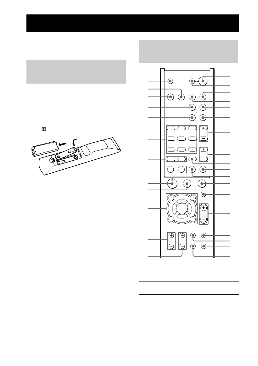
Operations Using the Remote RM-U700
You can use the remote RM-U700 to operate the
components in your system.
Before you use your remote
Inserting batteries into the
remote
Insert R6 (size-AA) batteries with the + and –
properly oriented in the battery compartment.
When using the remote, point it at the remote
sensor on the receiver.
Tip
Under normal conditions, the batteries should last for
about 6 months. When the remote no longer operates
the receiver, replace all batteries with new ones.
Notes
• Do not leave the remote in an extremely hot or humid
place.
• Do not use a new battery with an old one.
• Do not expose the remote sensor to direct sunlight or
lighting apparatuses. Doing so may cause a
malfunction.
• If you don’t use the remote for an extended period of
time, remove the batteries to avoid possible damage
from battery leakage and corrosion.
Remote button description
TV ?/1 AV ?/1
1
2
VIDEO DVD
SYSTEM STANDBY
3
4
5
6
7
8
9
q;
qa
DUAL
MONO
FM MODE
123
ANGLE
AUDIO
456
SWAP JUMP
TIME
789
MEMORY SHIFT
>
.
0/10 >10/11 ENTER/12
TUNING DISC ALT
M
m
ANT
CLEAR
H
TOP MENU/
GUIDE
F
G
ENTER
f
DISPLAY
TV VOL TV CH
qs
qd
The tables below show the settings of each
button.
Remote
Button
A.F.D. wh Receiver Selects A.F.D. AUTO.
ALT ws Remote When ALT button lights
Operations Function
?/1
SLEEP
SAT TV
AUX
TUNER
;
PL/PL A.F.D.
SOUND
FIELD
D.TUNING
SUBTITLE
PRESET/
CH/D.SKIP
-
SEARCH MODE
X
x
MUTING
AV MENU
MASTER
VOL
g
O
RETURN/EXIT
TV/
MAIN
VIDEO
MENU
TEST
TONE
WIDE
up, it changes the remote
key function to activate
those buttons with orange
printing.
ea
e;
wl
wk
wj
wh
wg
wf
wd
ws
wa
w;
ql
qk
qj
qh
qg
qf
30
GB
Page 31
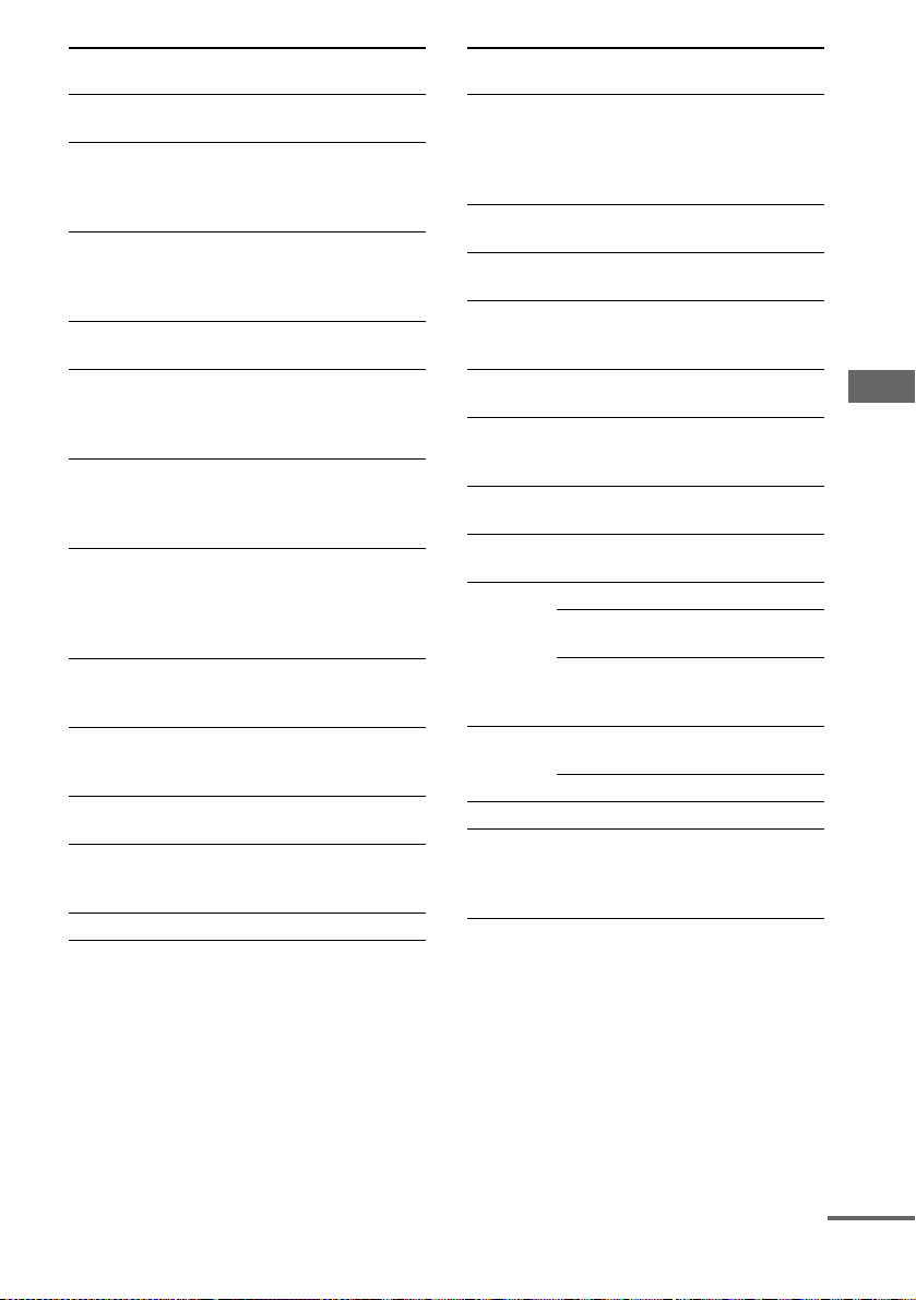
Remote
Button
ANGLE 6 DVD
Operations Function
Selects viewing angle or
recorder
changes the angles.
ANT 8 VCR Selects output signal
from the antenna
terminal: TV signal or
VCR program.
AUDIO 6 TV/VCR/
DVD
recorder
Changes the sound to
Multiplex or Bilingual
or Multi Channel TV
Sound.
AUX 4 Receiver To listen to an audio
equipment.
AV MENU qaVCR/
Displays menu.
satellite tuner/
DVD
recorder
AV ?/1 e;TV/VCR/
CD player/
DVD
Turns the audio and
video components on or
off.
recorder
CLEAR 8 DVD
recorder
Press if you make a
mistake when you press
the numeric button or
press to return to
continuous play etc.
DISC wa CD player Selects a disc directly
(multi-disc changer
only).
DISPLAY qaTV/VCR/
DVD
recorder
Selects information
displayed on the TV
screen.
D.TUNING 6Receiver Enters direct tuning
mode.
DUAL
MONO 6
Receiver Selects the language
you want during digital
broadcast.
DVD 2 Receiver To watch DVD.
Remote
Button
ENTER qa Receiver/
Operations Function
Enters the selection.
VCR/
satellite tuner/
DVD
recorder
ENTER/12 wdTV/VCR/
Enters the selection.
satellite tuner
FM MODE 6Receiver Selects FM monaural or
stereo reception.
JUMP 6 TV Toggles between the
previous and the current
channels.
MAIN
MENU qj
MASTER
VOL +/–
Receiver Selects the menu of the
receiver.
Receiver Adjusts the master
volume of the receiver.
qk
MEMORY 7Receiver Stores the radio stations.
MUTING qlReceiver Mutes the sound from
the receiver.
PRESET/ Receiver Selects preset stations.
CH/D.SKIP
+/– wf
TV/VCR/
satellite tuner
CD player/
DVD
Selects preset channel.
Skips discs (multi-disc
changer only).
recorder
RETURN/
EXIT/O
DVD
recorder
Returns to the previous
menu or exits the menu.
qa Satellite tuner Exits the menu.
SAT wk Receiver To watch satellite tuner.
SEARCH
MODE wa
DVD
recorder
Selects searching mode.
Press to select the unit
for search (track, index,
etc.)
Operations Using the Remote RM-U700
continued
31
GB
Page 32

Remote
Button
Operations Function
SHIFT wd Receiver Selects a memory
page for presetting
radio stations or
tuning to preset
stations.
SLEEP ea Receiver Activates the sleep
function and the
duration which the
receiver turns off
automatically.
SOUND
Receiver Selects sound fields.
FIELD +/–
wg
SUBTITLE 6DVD
Changes the subtitles.
recorder
SWAP* 6 TV Swaps the small and
large picture.
SYSTEM
STANDBY
(Press AV
?/1 e; and
?/1 ea at the
same time)
Receiver/
TV/VCR/
satellite tuner/
CD player/
DVD
recorder
Turns off the receiver
and other Sony audio/
video components.
TEST TONE qgReceiver Outputs test tone.
TIME 6 CD player/
DVD
recorder
TOP MENU/
GUIDE qa
DVD
recorder
Shows the time or
displays the playing
time of disc, etc.
Displays DVD title.
Satellite tuner Displays guide menu.
TUNER wj Receiver To listen to radio
programs.
TUNING
Receiver Scans radio stations.
–/+ 8
TV wl Receiver To watch TV
programs.
TV CH +/– qdTV Selects preset TV
channels.
Remote
Button
Operations Function
TV/VIDEO qhTV Selects input signal:
TV input or video
input.
TV VOL
+/– qs
TV Adjusts the volume of
the TV.
TV ?/1 1 TV Turns the TV on or off.
VIDEO 3 Receiver To watch VCR.
WIDE qf TV Selects the wide
picture mode.
1-9 6 and
0/10 7
Receiver Use with SHIFT to
preset radio station or
tuning to preset
stations and with
D.TUNING for direct
tuning.
CD player Selects track numbers.
0/10 selects track 10.
TV/VCR/
satellite tuner
Selects channel
numbers.
>10/11 7 CD player Selects track numbers
over 10.
-/-- wa TV Selects the channel
entry mode, either one
or two digit.
?/1 ea Receiver Turns the receiver on
or off.
;PL/PLII 5Receiver Selects DOLBY PL,
PLII MOV or PLII
MUS.
V/v qa Receiver Selects a menu item.
B/b qa Receiver Adjusts or changes the
setting.
V/v/B/b qa VCR/
satellite tuner/
DVD
Selects a menu item.
Press to enter the
selection.
recorder
* Only for Sony TVs with the picture-in-picture
function.
GB
32
Page 33
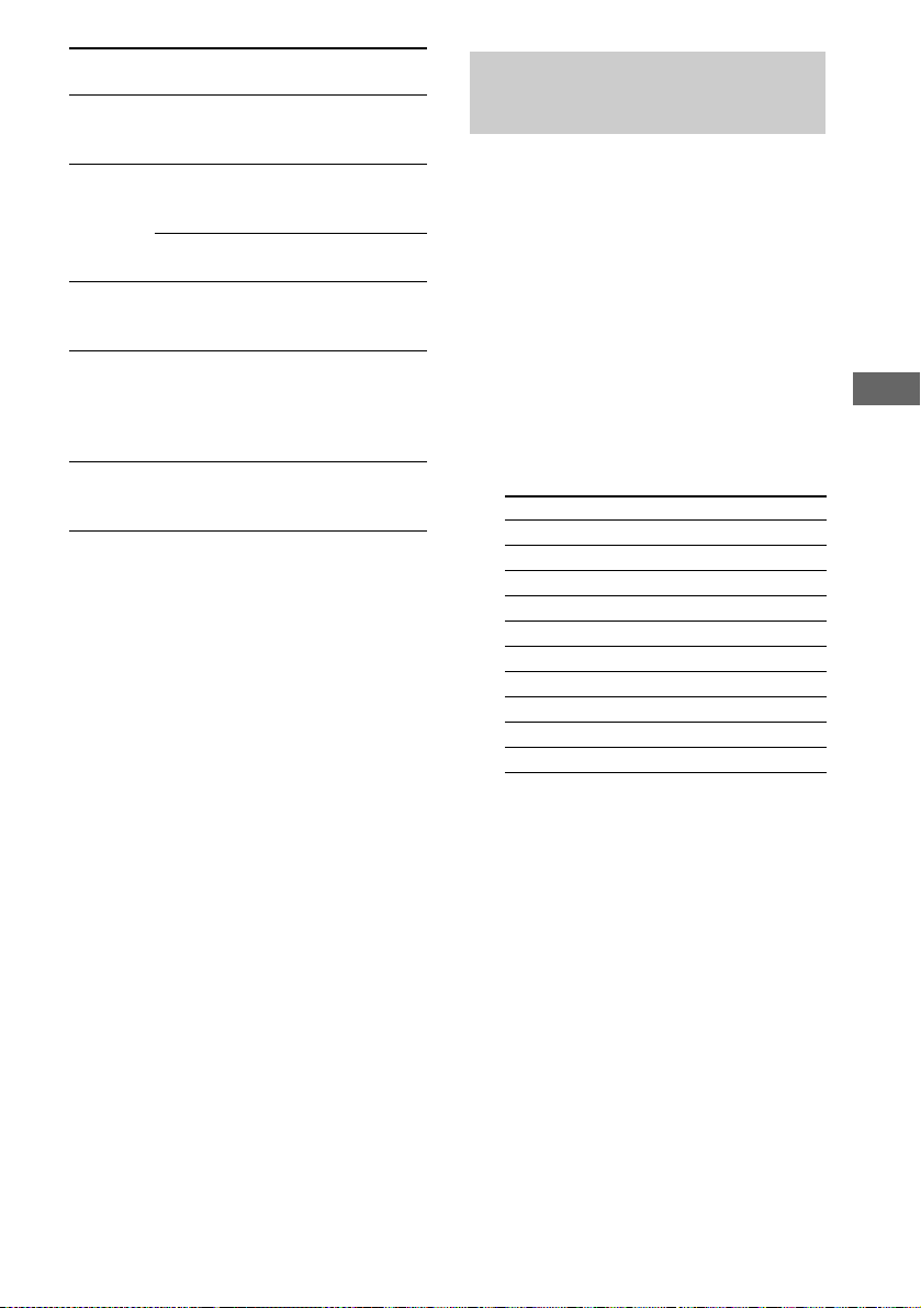
Remote
Button
./> 7VCR/
m/M 8CD player/
H 9 VCR/
X q; VCR/
x w; VCR/
Notes
• The AUX button on the remote is not available for
receiver operation.
• When you press the input buttons (VIDEO, DVD),
the input mode of the TV might not switch to the
corresponding input mode tha t you want. In this case,
press the TV/VIDEO button to switc h the input mode
of the TV.
• To activate the buttons with orange printing, press
ALT first before pressing the buttons.
• Some functions explained in this section may not
work depending on the model.
• The above explanation is intended to serve as an
example only. Therefore, depending on the
component the above operation may not be possible
or may operate differently than described
Operations Function
CD player/
DVD recorder
DVD recorder
VCR Fastforwards or
CD player/
DVD recorder
CD player/
DVD recorder
CD player/
DVD recorder
Skips tracks.
Searches tracks in the
forward or backward
direction.
rewinds.
Starts playblack.
Pauses playblack or
record. (Also starts
recording with
components in
recording standby.)
Stops playback.
.
Changing the factory setting of an input button
If the factory settings of the input buttons do not
match your system components, you can change
them. For example, if you have a CD player and
you do not have a DVD recorder, you can assign
the DVD button to your CD player.
1 Hold down the input button whose
input you want to change (for example,
DVD).
2 Press the corresponding button of the
component you want to assign to the
input button (for example, 1 – CD
player).
The following buttons are assigned to select
the input:
To operate Press
CD player 1
VCR (command mode VTR 2*) 2
VCR (command mode VTR 3*) 3
DVD recorder 4
TV 5
DSS (Digital Satellite Receiver) 6
Tuner (this receiver) 7
DCS (Digital CS Tuner) 8
BSD (Digital BS Tuner) 9
Tuner (Component tuner) 0/10
*Sony VCRs are operated with a VTR 2 or 3
setting. These correspond to 8mm and VHS
respectively.
Now you can use the DVD button to control
the CD player.
To reset a button to its factory
setting
Repeat the above procedure.
To reset all the input buttons to
their factory setting
Press ?/1, AV ?/1 and MASTER VOL – at the
same time.
Operations Using the Remote RM-U700
33
GB
Page 34

Additional Information
Precautions
On safety
Should any solid object or liquid fall into the cabinet,
unplug the receiver and have it checked by qualified
personnel before operating it any further.
On power sources
• Before operating the receiver, check that the
operating voltage is identical with your local power
supply. The operating voltage is indicated on the
nameplate at the rear of the receiver.
• The receiver is not disconnected from the AC power
source (mains) as long as it is connected to the wall
outlet, even if the receiver itself has been turned off.
• If you are not going to use the receiver for a long
time, be sure to disconnect the receiver from the wall
outlet. To disconnect the AC power cord, grasp the
plug itself; never pull the cord.
• AC power cord must b e changed only at the qualified
service shop.
On heat buildup
Although the receiver heats up during operation, this is
not a malfunction. If you continuously us e this receiver
at a large volume, the cabinet temperature of the top,
side and bottom rises considerably. To avoid burning
yourself, do not touch the cabinet.
On placement
• Place the receiver in a location with adequate
ventilation to prevent heat buildup and prolong the
life of the receiver.
• Do not place the receiver near heat sources, or in a
place subject to direct sunlight, excessive dust or
mechanical shock.
• Do not place anything on top of the cabinet that
might block the ventilation holes and cause
malfunctions.
• Use caution when placing the receiver or speakers on
surfaces that have been specially treated (with wax,
oil, polish, etc.) as staining or discoloration of the
surface may result.
On operation
Before connecting other components, be sure to turn
off and unplug the receiver.
If you encounter color irregularity on a
nearby TV screen
The speakers and the sub woofer are magnetically
shielded to allow it to be installed near a TV set.
However, color irregularities may still be observed
on certain types of
TV sets.
If color irregularity is observed...
Turn off the TV set once, then turn it on again after
15 to 30 minutes.
If color irregularity is observed again...
Place the speaker further away from the TV set.
If howling occurs
Reposition the speakers or turn down the volume on
the receiver.
On cleaning
Clean the cabinet, panel and controls with a soft cloth
slightly moistened with a mild detergent solution. Do
not use any type of abrasive pad, scouring powder or
solvent such as alcohol or benzine.
If you have any question or problem concerning your
receiver, please consult your nearest Sony dealer.
34
GB
Page 35
Troubleshooting
If you experience any of the following
difficulties while using the receiver, use this
troubleshooting guide to help you remedy the
problem.
There is no sound or only a very low-level
sound no matter which component is
selected.
• Check that the speakers and components are
connected securely and correctly.
• Check that both the receiver and all components
are turned on.
• Check that you have selected the correct
component on the receiver.
• Check that MASTER VOLUME on the receiver is
not set at
“VOL MIN”.
• Press MUTING to cancel the muting function.
There is no sound from a specific component.
• Check that the component is connected correctly
to the audio input jacks for that component.
• Check that the cord(s) used for the connection is
(are) fully inserted into the jacks on both the
receiver and the component.
• Check that you have selected the correct
component on the receiver.
There is no sound from one of the front
speakers.
• Check that the component is connected correctly
to the audio input jacks for that component.
• Check that the cord(s) used for the connection is
(are) fully inserted into the jacks on both the
receiver and the component.
The left and right sounds are unbalanced or
reversed.
• Check that the speakers and components are
connected correctly and securely.
• Adjust balance parameters in the LEVEL menu.
There is severe hum or noise.
• Check that the speakers and components are
connected securely.
• Check that the connecting cords are away from a
transformer or motor, and at least 3 meters away
from a TV set or fluorescent light.
• Move your TV away from the audio components.
• The plugs and jacks are dirty. Wipe them with a
cloth slightly moistened with alcohol.
There is no sound or only a very low-level
sound is heard from the center or/and
surround speakers.
• Make sure the sound field function is on (press
SOUND FIELD + or SOUND FIELD –).
• Select a CINEMA STUDIO EX mode (page 24).
• Adjust the speaker level (page 16).
There is no sound from the sub woofer.
• Check that the sub woofer is connected correctly
and securely.
The surround effect cannot be obtained.
• Make sure the sound field function is on (press
SOUND FIELD + or SOUND FIELD –).
• Sound fields do not function for the signals with a
sampling frequency of more than 48 kHz.
Dolby Digital or DTS multi channel sound is
not reproduced.
• Check that the playing DVD, etc. is recorded in
Dolby Digital or DTS format.
• When connecting the DVD recorder, etc. to the
digital input jacks of this receiver, check t he audio
setting (settings for the audio output) of the
connected component.
Additional Information
continued
35
GB
Page 36
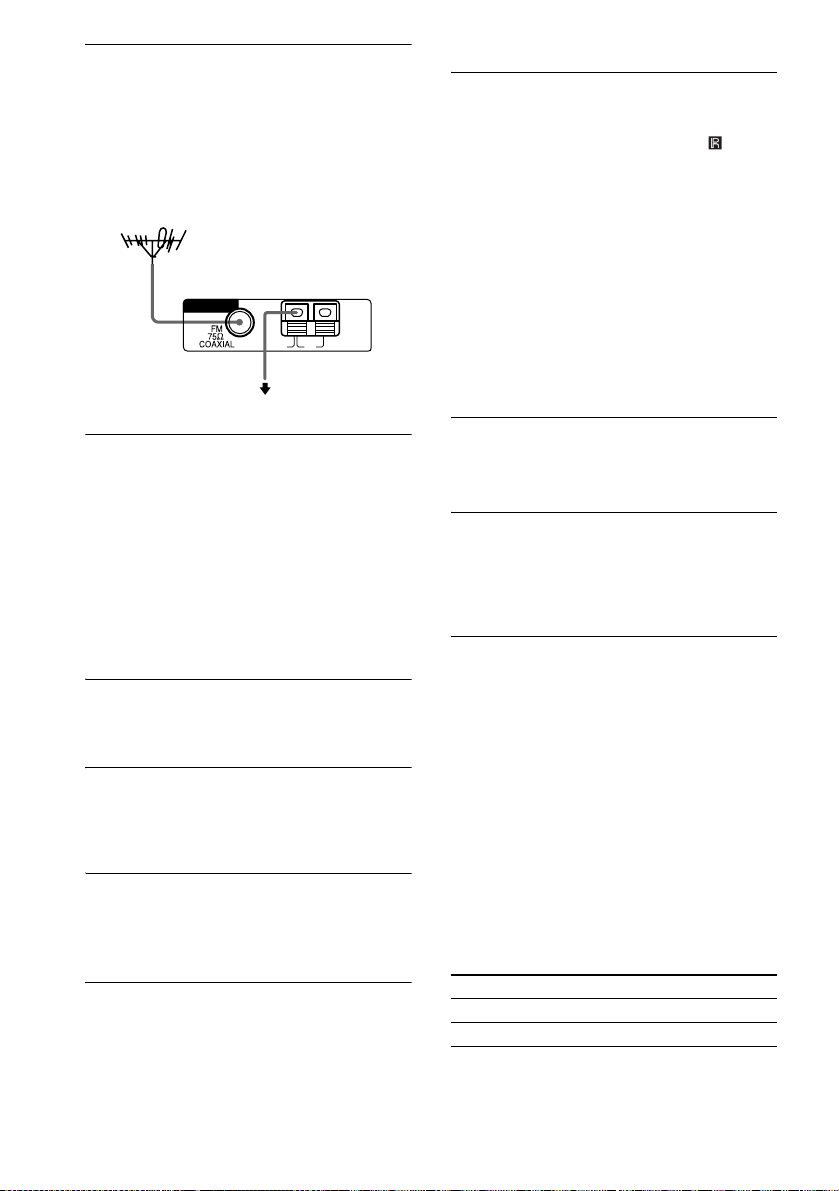
The FM reception is poor.
• Use a 75-ohm coaxial cable (not supplied) to
connect the receiver to an outdoor FM antenna as
shown below. If you connect the receiver to an
outdoor antenna, ground it against lightning. To
prevent a gas explosion, do not connec t the ground
wire to a gas pipe.
Outdoor FM antenna
Receiver
ANTENNA
AM
U
Ground wire
(not supplied)
To ground
Remote control
The remote does not function.
• The AUX button on the remote is not available for
receiver operation.
• Point the remote at the remote sensor on the
receiver.
• Remove any obstacles in the path between the
remote and the receiver.
• Replace all the batteries in the remote with new
ones, if they are weak.
• Make sure you select the correct input on the
remote.
• To activate the buttons with orange printing, press
ALT first before pressing the buttons.
• Before you use the V/v/B/b button fo r receiver
operation, press MAIN MENU. To operate other
components, press TOP MENU/GUIDE or AV
MENU after pressing the function button.
Radio stations cannot be tuned in.
• Check that the antennas are connected securely.
Adjust the antennas and connect an external
antenna if necessary.
• The signal strength of the stations is too weak
(when tuning in with automatic tun ing). Use direct
tuning.
• Make sure you set the tuning interval correctly
(when tuning in AM stations with direct tuning).
• No stations have been preset or the preset stations
have been cleared (when tuning by scanning
preset stations). Preset the stations (page 19).
RDS does not work.
• Make sure that you are tuned to an FM RDS
station.
• Select a stronger FM station.
The RDS information that you want does not
appear.
• Contact the radio station and find ou t whether they
actually provide the service in question. If so, the
service may be temporarily out of order.
There is no picture or an unclear picture
appears on the TV screen or monitor.
• Select the appropriate input on the receiver.
• Set your TV to the appropriate input mode.
• Move your TV away from the audio components.
Error message
If there is a malfunction, the display shows a
message.
PROTECT
Irregular current is output from the speakers. The
receiver will automatically turn off after a few
seconds. Check the speaker connection and turn on
the power again. If this problem persists, consult
your nearest Sony dealer.
If you are unable to remedy the
problem using the
troubleshooting guide
Clearing the receiver’s memory may remedy the
problem (page 13). However, note that all
memorized settings will be reset to their factory
settings and you will have to readjust all settings
on the receiver.
If the problem persist
Consult your nearest Sony dealer.
Reference sections for clearing
the receiver’s memory
To clear See
All memorized settings page 13
Customized sound fields page 27
36
GB
Page 37
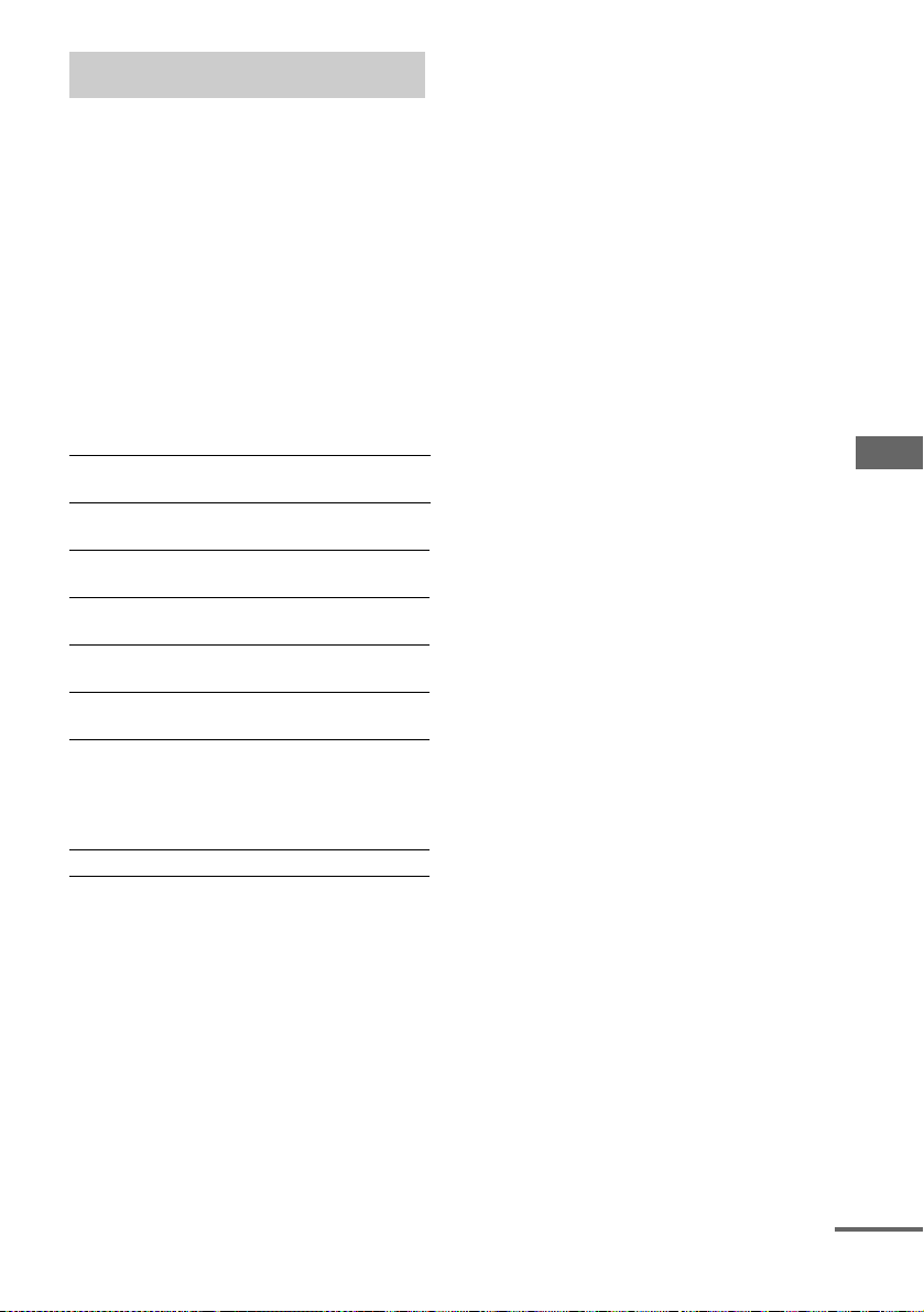
Specifications
Amplifier section
Power Output
(6 ohms 1 kHz, THD 0.7%)
(6 ohms 1 kHz, THD 10%)
1) Measured under 230 V AC, 50 Hz
2) Depending on the sound field settings and the
source, there may be no sound output.
Inputs (Analog)
TV/SAT, DVD, VIDEO Sensitivity: 500 mV
Inputs (Digital)
DVD (Coaxial) Sensitivity: –
DVD, TV/SAT (Optical) Sensitivity: –
Outputs (Analog)
SUB WOOFER Voltage: 2 V
Reproduction frequency range:
Tone
Gain levels ±6 dB, 1 dB step
FM tuner section
Tuning range 87.5 - 108.0 MHz
Antenna FM wire antenna
Antenna terminals 75 ohms, unbalanced
Intermediate Frequency 10.7 MHz
AM tuner section
Tuning range
With 9-kHz tuning scale: 531 - 1,602 kHz
Antenna Loop antenna
Intermediate Frequency 450 kHz
1)
FRONT2): 40 W/ch
2)
CENTER
SURR
1)
FRONT2): 60 W/ch
CENTER
SURR
Impedance: 50 kiloohms
Impedance: 75 ohms
Impedance: –
Impedance: 1 kiloohms
28 – 20,000 Hz
: 40 W
2)
: 40 W/ch
2)
: 60 W
2)
: 60 W/ch
Video section
Inputs/Outputs
Video: 1 Vp-p, 75 ohms
General
Power requirements 230 V AC, 50/60 Hz
Power consumption 170 W
Power consumption (during standby mode)
0.3 W
Dimensions (w/h/d) (Approx.)
430 × 352 × 66 mm
including projecting parts
and controls
Mass (Approx.) 5.5 kg
Speaker section
Front speakers
• HTR-6600 (SS-SLP701)
• HTR-6100 (SS-MSP501)
Center speaker (SS-CNP501)
Surround speakers (SS-MSP501)
Speaker system Full range, magnetically
shielded
Speaker units
SS-SLP701 40 × 70 mm cone type
SS-MSP501/SS-CNP501 55 × 110 mm cone type
Enclosure type Bass reflex
Rated Impedance 6 ohms
Dimension (w/h/d) (Approx.)
SS-SLP701 246 × 1053 × 246 mm
SS-CNP501 280 × 82 × 106 mm
SS-MSP501 76 × 162 × 106 mm
Mass (Approx.)
SS-SLP701 4.0 kg
SS-MSP501 0.8 kg
SS-CNP501 1.0 kg
Sub woofer (SA-WMSP601)
Speaker system Active subwoofer,
magnetically shielded
Speaker unit 200 mm cone type
Enclosure type Acoustically loaded bass
reflex
RMS output 175 W (5 ohms, 100 Hz,
10% THD)
Frequency range: 30 Hz – 200 Hz
Input LINE IN (input pin jacks)
Power requirements 230 V AC, 50/60 Hz
Power consumption 120 W
Dimensions (w/h/d) (Approx.)
270 × 325 × 398 mm
including front panel
Mass (Approx.) 10 kg
Additional Information
continued
37
GB
Page 38

Supplied accessories
FM wire antenna (1)
AM loop antenna (1)
Speaker connecting cord (5)
Monaural connecting cord (1)
Coaxial digital cord (1)
Foot pads (speakers)
• HTR-6600 (12)
• HTR-6100 (20)
Foot pads (subwoofer) (4)
Remote commander (1)
R6 (size-AA) batteries (2)
Speakers
• Front speakers (2)
• Center speaker (1)
• Surround speakers (2)
• Sub woofer (1)
Design and specifications are subject to change
without notice.
38
GB
Page 39
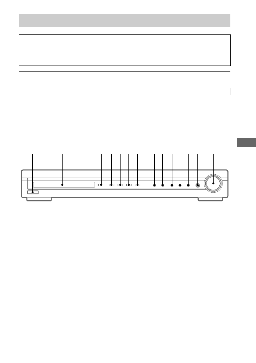
List of button locations and reference pages
Illustrati
1 2 3 4 5 6 8 9 q;qaqsq
q
7
How to use pages 39
Use this page to find the location of buttons that are
mentioned in the text.
Main unit
ALPHABETICAL ORDER
Display 2 (20)
DVD (indicator) 5 (17)
INPUT SELECTOR
19)
IR (receptor) 3 (30, 36)
MASTER VOLUME qf (16, 17,
35)
qd (17, 18,
MUTING qs (17, 35)
PRESET TUNING + 9 (19)
PRESET TUNING – 8 (19)
SOUND FIELD qa (27)
TUNER (indicator) 7 (17)
TV/SAT (indicator) 6 (17)
VIDEO (indicator) 4 (17)
on number
r
INPUT SELECTOR qd (17, 18, 19)
Name of button/part Reference page
RR
NUMBERS AND SYMBOLS
?/1 (power) 1 (13, 16, 18)
; PLII q; (24)
d
f
Additional Information
GB
39
Page 40

Index
A
Adjusting
LEVEL parameter 26
SET UP parameters 14, 28
speaker levels and balance 16
TONE parameter 27
Automatic tuning 17
C
Clearing receiver’s memory 13
D
Digital Cinema Sound 24
Direct tuning 18
Dual Mono 28
L
LEVEL menu 26
P
Preset stations
how to 19
how to tune 19
R
RDS 20
S
Selecting
component 17
sound field 24–25
SET UP menu 14, 28
Sleep Timer 29
Sound field
customizing 26
pre-programmed 24–25
resetting 27
selecting 24–25
Speakers
adjusting speaker levels and balance 16
connection 10
placement 10
Supplied accessories 38
T
Test tone 16
TONE menu 27
Tuning
automatically 17
directly 18
to preset stations 19
Sony Corporation
Printed in Hungary
 Loading...