

Sony MKS-R4020, MKS-E1620 Operating Instructions Manual

5-012-212-11 (1)
40 LCD Button Remote Control
Panel
MKS-R4020
16 Rotary Encoder Remote Control
Panel
MKS-E1620
Operating Instructions
© 2019 Sony Corporation

Table of Contents
Overview ............................................................. 3
Features ......................................................................... 3
Connection Mode Settings ............................................ 3
System Connection Example .........................................4
Locations and Functions of Parts ......................... 5
Front Panel ..................................................................... 5
Rear Panel ...................................................................... 5
Preparations........................................................ 6
Notes on Installation ..................................................... 6
Setting Up the Unit ........................................................ 6
Connections with System Controllers and LEO ............ 6
Configuring Using the Buttons ...................................... 7
Operations .......................................................... 7
LEO Operation ............................................................... 7
NS-BUS Operation ......................................................... 7
Switching a Different Source for Each Level
(Breakaway) ...............................................................10
Switching Multiple Crosspoints Simultaneously
(Salvo) ........................................................................ 11
Pages and Page Groups ...............................................12
Switching and Monitoring Two Sources (Chop) ..........12
Preventing Source Switching for Destinations
(Protect) .....................................................................13
Preventing Accidental Operation (Lock) ......................13
Monitoring Destinations ...............................................13
Level Control .................................................................13
Retrace Function ...........................................................13
Linkage Function ..........................................................13
Web Menu .......................................................... 14
Displaying the Web Menu ............................................14
Screen Configuration ....................................................14
Panel Table Page ..........................................................15
Source Reentry Lists Page ............................................15
Salvo Table Page ..........................................................16
Available Src/Dest Page ...............................................16
Control Area Page ........................................................16
Alias Name Lists Page .................................................. 17
Default Controls Page ..................................................17
Operation Settings Page .............................................. 17
Display Settings Page ...................................................18
Retrace Settings Page ..................................................19
Linkage Settings Page ..................................................19
Page Group Settings Page .......................................... 20
Network Settings Page ................................................ 20
Remote Maintenance Page ......................................... 20
Time Settings Page .......................................................21
System Page .................................................................21
Usage Precautions............................................. 22
Error/Warning Messages .................................. 23
Specifications .................................................... 25
2

Overview
Different sources for each level are selectable (NSBUS operation)
You can select and display different sources for each level
using the breakaway function.
The MKS-R4020/MKS-E1620 is a remote control panel that
connects to Live Element Orchestrator (LEO) and is used to
change system configuration, register devices, and
configure device settings. The MKS-R4020 can also
connect to a PWS-100NM1/110NM1 running IP Live System
Manager (system controller) to switch the routing of video
signals and audio signals. You can use the selection
buttons on this unit to switch the source/destination of
signals of Networked Media Interface devices or to switch
the source/destination of a routing switcher.
Features
Large buttons that display functions in different
colors
Employs large LCD buttons on the front panel designed for
easy operation.
The color and brightness of LCD buttons can be configured
so that the button function and the current selection status
are visible at a glance.
You can set the button color and brightness in the web
menu to suit the operating environment to make the
buttons more visible.
Self-diagnostics function
The unit automatically performs self-diagnostics, such as
communications status checks. The diagnostics results
appear in the display window.
System redundancy support
The unit features dual power supplies and networks to
support system redundancy.
Monitor function to watch the selection status of
other outputs (NS-BUS operation)
When a destination you wish to monitor is set as a monitor
destination, the source automatically switches to the same
source as the monitor destination when the monitor
function is set to ON.
Switching between two sources alternately (chop
function) (NS-BUS operation)
The chop function switches between two sources
alternately at a specified interval automatically.
Switching of multiple crosspoints using a single
operation (salvo function) (NS-BUS operation)
When multiple crosspoints have been selected and a salvo
is defined beforehand using the web menu, all the
crosspoints set for the salvo can be switched by pressing
one button.
Display window for each LCD button (NS-BUS
operation)
The LCD buttons themselves are display windows. Each
LCD button has a 2-line, 8-character display window. The
source name is displayed in the display window of source
selection buttons, and the destination name is displayed
in the display window of destination selection buttons.
Status display function (NS-BUS operation)
The currently selected source name, destination name,
and any error messages are displayed.
Connection Mode Settings
LEO/NS-BUS control support (MKS-R4020)
The MKS-R4020 supports two operating modes: “LEO
operation” where it connects to LEO to control the setup
and operation of each device, and “NS-BUS operation”
where it connects to a system controller to control the
routing of video and audio signals.
LCD buttons used for selecting both sources and
destinations (NS-BUS operation)
All LCD buttons on the front panel can be used as source
selection buttons or destination selection buttons
according to settings in the web menu. The current setting
can be easily discerned by the color of the button when lit.
Controllable up to 128 levels1) (NS-BUS operation)
Up to 128-level (128 signals) control is supported using
settings configured using the web menu.
1) Levels
To handle different kinds of signals simultaneously, it is
necessary to use a routing switcher for each type of signal. For
example, a recording to be made on a VTR requires the use of
five signal levels: video, audio 1, audio 2, timecode and remote
control signals. These are collectively referred to as levels.
The remote control panel supports three connection
modes for operation.
The MKS-E1620 supports LEO connection mode only. The
MKS-R4020 supports LEO connection mode, NS-BUS
connection mode, and Hybrid connection mode.
LEO connection mode
The unit connects to LEO to support LEO operation.
NS-BUS connection mode
The unit connects to a system controller to support NS-BUS
operation.
Hybrid connection mode
The unit connects to LEO and a system controller
simultaneously to support both LEO operation and NS-BUS
operation, and can switch operation.
LEO operation
The unit communicates with LEO to configure and control
each device connected to LEO.
In LEO operating mode, all settings for the LCD buttons and
rotary encoders of the remote control panel are made from
LEO.
3
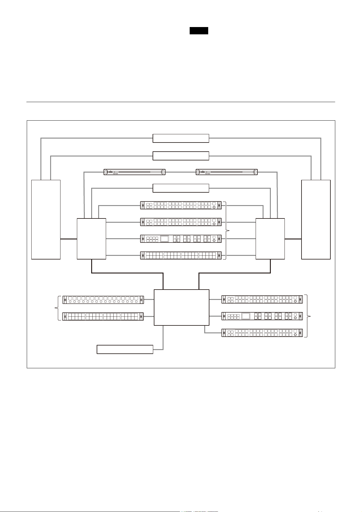
NS-BUS operation
NMI/ST2110
IP Live System Manager (B) IP Live System Manager (A)
NMI/ST2110
LEO
L3 switch
(For AV)
L3 switch
(For AV)
L2 switch
(For control)
L2 switch
(For control)
MKS-R3210
MKS-R1620
MKS-R1630
MKS-R4020
L3 switch
(For control)
MKS-E1620
MKS-R4020
Routing switcher
MKS-R3210
MKS-R1630
MKS-R1620
Single LAN
connection
Single LAN
connection
Dual LAN
connection
The unit communicates with a system controller to switch
the routing of video signals and audio signals.
In NS-BUS operating mode, all settings for the LCD buttons
and rotary encoders of the remote control panel are made
from the web menu.
System Connection Example
Notes
• When started in Hybrid connection mode, LEO operating
mode is enabled at startup.
• To switch from LEO operation to NS-BUS operation in
Hybrid connection mode, buttons must be configured
from LEO.
• To switch from NS-BUS operation to LEO operation in
Hybrid connection mode, buttons must be configured
from the web menu.
4
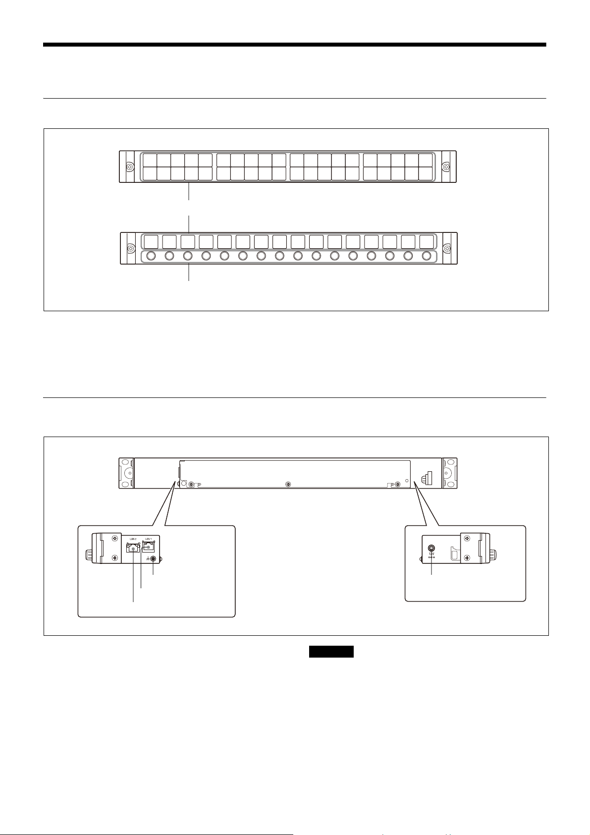
Locations and Functions of Parts
LCD buttons
Rotary encoders
MKS-R4020
MKS-E1620
(ground) terminal
LAN1 port
LAN2 port
DC IN connector
Front Panel
LCD buttons
When connected to a system controller, these buttons can
be used as source selection buttons, destination selection
buttons, or level selection buttons. You can configure the
type of selection of the buttons using the web menu or the
assignment function.
Rear Panel
When connected to LEO, the settings of the LCD buttons
are made from LEO.
Rotary encoders
The function of each encoder is set by LEO.
(ground) terminal
For signal grounding.
LAN1 (PoE) port
Connect to the network on which the system controller or
LEO is connected (network 1). This port accepts power
using PoE.
CAUTION for LAN port
The LAN port of this unit is to be connected only to the
devices whose power feeding meets the requirements for
SELV (Safety Extra Low Voltage) and complies with Limited
Power Source according to IEC 60950-1.
CAUTION
When you connect the LAN cable of the unit to peripheral
device, a shielded-type cable is strongly recommended to
prevent malfunction due to radiation noise and
electrostatic noise.
LAN2 port
Connect to the network with system controller connected
(network 2).
5
CAUTION for LAN port
MKS-R4020
LAN1
IP Live System Manager
or
LEO
MKS-R4020
LAN1
IP Live System Manager (A)
LAN2
IP Live System Manager (B)
For safety, do not connect the connector for peripheral
device wiring that might have excessive voltage to the
following port:
•LAN2 port
Preparations
Notes
• When you connect the LAN cable of the unit to
peripheral device, a shielded-type cable is strongly
recommended to prevent malfunction due to radiation
noise and electrostatic noise.
• If a redundancy configuration is not used on the
network, use the LAN1 port.
DC IN connector
Connect to the supplied AC adapter.
Notes on Installation
For installing the unit in a 19-inch rack
When installing in a 19-inch rack, use binding-head screws
(+B5×10, 7-682-575-04).
For use in an OB van
When the unit is to be used in an OB van, be sure to bind
the cables to a rack strut to avoid having the weight of
cables add to vibration shock to the connector on the side
panel during transport.
Setting Up the Unit
First, configure the network preferences using the buttons
on the unit. For details about network preferences and
connection mode settings, refer to the Installation Manual.
You can enter the IP address specified for the unit in a web
browser to display the web menu. Use the web menu to
configure detailed settings.
Connections with System Controllers
and LEO
A remote control panel can be connected in a single
system connection or in a redundancy system connection.
Several modes are supported for redundancy system
connections.
Single system connection
A single system connection is the simplest connection
type.
Use LAN1.
Dual LAN redundancy system connection
A dual system redundancy structure uses both LAN1 and
LAN2 of the remote control panel.
Operation will continue in the event of a single system
switch failure.
Note
When using a dual LAN1 and LAN2 system connection, do
not use IP addresses for the same segment.
6
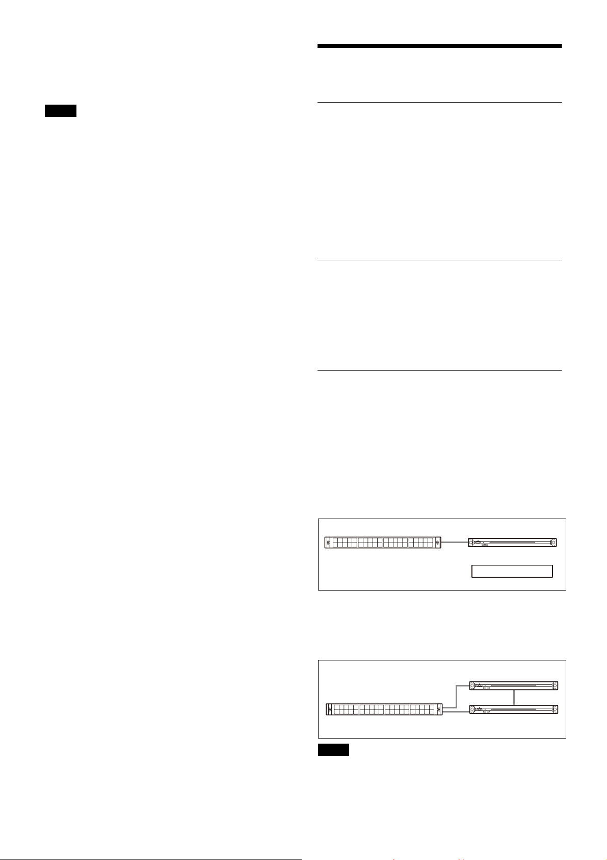
Single LAN redundancy system connection
MKS-R4020
LAN1
IP Live Syst em Ma nager (A)
IP Live System Manager (B)
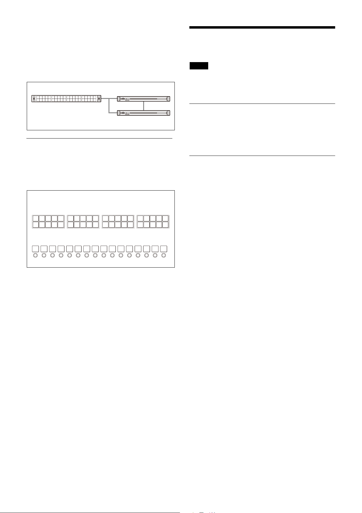
1234
21 22 23 24525
678 9
26 27 28 291030
11 12 13 14
31 32 33 341535
16 17 18 19
36 37 38 392040
12345678910111213141516
LCD button numbers
MKS-R4020
MKS-E1620
A single system redundancy structure uses only LAN1 of
the remote control panel.
The wiring for LAN1 only is connected, but the panel
connects to both system A and system B. This
configuration is useful if you want to reduce the LAN cable
wiring or if there are no available ports on a switch.
Use LAN1.
Configuring Using the Buttons
Operations
Note
This section describes typical operation on the
MKS-R4020. For other models, substitute the button
names and other items corresponding to your model.
LEO Operation
In LEO operating mode, all the LCD buttons and rotary
encoders are configured and controlled from LEO. For
details, refer to the User Manual of Live Element
Orchestrator.
Basic settings of the unit can be configured using the web
menu, but the following settings can also be configured
directly on the unit. The following items can be set on the
unit by turning the power on while pressing a combination
of LCD buttons, as described below.
Setting the default IP address
Simultaneously press buttons 1 and 2, then turn the power
on.
For details about the IP address setting, refer to the
Installation Manual.
Resetting the software
On the MKS-E1620, press and hold buttons 1, 3, and 4
simultaneously for three seconds or longer. On the
MKS-R4020, press and hold buttons 21, 23, and 24, for
three seconds or longer. The software is reset, and the unit
returns to the same status as when power is first turned
on.
NS-BUS Operation
On the MKS-R4020, all the LCD buttons can be configured
as selection buttons or function buttons. You can assign a
crosspoint switching function, or a source or destination to
a selection button. You can assign a function that performs
an operation to a function button. The required functions
to perform operations must be assigned to the function
buttons beforehand. For details about button assignment,
“Panel Table Page” (page 15)
see
Selection buttons and function buttons
On the MKS-R4020, the LCD buttons function as either
selection buttons or function buttons. The selection button
or function button assignment is configured on the [Panel
Table] page of the web menu. For details about
assignment, see
menu section.
Selection buttons
A selection button is a button that is assigned a source,
destination, Level function, or Monitor function, and that
assignment can be changed for each page. For details
about pages, see
details about as signment, see
in the web menu section.
Level function: A button assigned with the Level function
becomes a LEVEL button. When a LEVEL button is
pressed, the level specified by that button becomes
active. For details about levels, see
(page 11)
Monitor function: A button assigned with the Monitor
function becomes a MONI button. For details about the
MONI button, see
“Panel Table Page” (page 15)
“Pages and Page Groups” (page 12)
.
“Monitoring Destinations” (page 13)
in the web menu section.
in the web
. For
“Panel Table Page” (page 15)
“About levels”
.
Function buttons
Only one function button assignment is supported on each
page. For details about assignment, see
Page” (page 15)
in the web menu section.
The following functions can be assigned.
Monitor function: A button assigned with the Monitor
function becomes a MONI button. For details about the
MONI button, see
“Monitoring Destinations” (page 13)
Status function: A button assigned with the Status
function becomes a STATUS button. The STATUS button
normally displays the name of the control destination.
Each time you press the STATUS button, the displayed
7
“Panel Table
.

content changes between the name of the control
destination and name of the connected source, the
name of the control destination only, and the name of
the source connected to the control destination only. If
an error occurs, an error message appears.
Protect function: A button assigned with the Protect
function becomes a PROT button. For details about the
PROT button, see
Destinations (Protect)” (page 13)
Lock (Chop) function: A button assigned with the Lock
(Chop) function becomes a LOCK(CHOP) button. For
details about the LOCK(CHOP) button, see
Accidental Operation (Lock)” (page 13)
and Monitoring Two Sources (Chop)” (page 12)
Assign function: A button assigned with the Assign
function becomes an ASSIGN button. For details about
the ASSIGN button, see
destination to a selection button (Assign)” (page 9)
Source, Destination/Level function: A button assigned
with the Source, Destination/Level function becomes a
SRC,DEST/LEVEL button. For details about the
SRC,DEST/LEVEL button, see
“Preventing Source Switching for
.
“Preventing
and
“Switching
.
“Assigning a source/
“Switching between
.
source selection mode and destination selection
mode” (page 8)
“Level Control” (page 13)
see
Entry function: A button assigned with the Entry function
becomes an ENTRY button. For details about the ENTRY
button, see
. For details about the Level function,
.
“Switching between BPS (button per
source) selection method and MD (multi destination)
selection method” (page 8)
Page Up/Group Up function, Page Down/Group Down
function: A button assigned with the Page Up/Group
Up function becomes a PG UP/GP UP button. A button
assigned with the Page Down/Group Down function
becomes a PG DN/GP DN button. For details about the
PG UP/GP UP button and PG DN/GP DN button, see
“Pages and Page Groups” (page 12)
Group Up/Group Down function: A button assigned with
the Group Up function becomes a GP UP button. A
button assigned with the Group Down function
becomes a GP DN button. For details about the GP UP
button and GP DN button, see
Groups” (page 12)
Shift function: A button assigned with the Shift function
becomes a SHIFT button. Used for level selection using
the SRC,DEST/LEVEL button and when switching
groups using the PG UP/GP UP and PG DN/GP DN
buttons.
Home function: A button assigned with the Home function
becomes a HOME button. When a remote control panel
is configured in Hybrid connection mode, pressing this
returns to the LEO home page and does not switch to
LEO operating mode.
Back function: A button assigned with the Back function
becomes a BACK button. When a remote control panel
is configured in Hybrid connection mode, pressing this
returns to the previous LEO page and does not switch
to LEO operating mode.
.
.
.
“Pages and Page
Switching between source selection mode
and destination selection mode
You can switch between source selection mode and
destination selection mode by pressing the SRC,DEST/
LEVEL button.
Note
The SRC,DEST/LEVEL button is required.
Destination selection mode
1 Press the SRC,DEST/LEVEL button so that the
SRC,DEST/LEVEL button lights up bright amber.
The names of destinations are displayed on selection
buttons assigned with a source/destination or a
destination only. The names of sources are displayed
on selection buttons assigned with a source only.
Source selection mode
1 Press the SRC,DEST/LEVEL button so that the
SRC,DEST/LEVEL button lights up bright green.
The names of sources are displayed on selection
buttons assigned with a source/destination or a
source only. The display configured on the [Display
Settings] page of the web menu is displayed on
selection buttons assigned with a destination only.
Switching between BPS (button per source)
selection method and MD (multi destination)
selection method
Crosspoints can be switched using the BPS selection
method or MD selection method. For details about
switching the selection method, see
(page 18)
section. You can select BPS Only, MD Only, or BPS/MD.
When BPS/MD is selected, you can switch the selection
method by pressing the ENTRY button. When BPS Only is
selected, you can switch to MD Only, and vice versa.
in “Operation Settings Page” in the web menu
Switching the control destination
The control destination can be switched at startup, when
switching pages, or when a selection button assigned with
a destination is pressed.
At startup or when switching pages
Configure settings as described in
(page 17)
in the web menu section.
When a selection button is pressed
In the BPS (button per source) selection method in
destination selection mode, or in the MD (multi
destination) selection method in source selection mode,
press a selection button assigned with a destination to
make that destination the control destination.
In the BPS (button per source) selection method in source
selection mode, press a selection button assigned with a
destination only to make that destination the control
destination.
Switching crosspoints
The source names and destination names for the selection
buttons on the front panel are configured using the web
menu. Using these buttons, you can select a source and
destination for switching a crosspoint.
Changing the selection method
Set the selection method as described in
between BPS (button per source) selection method and
MD (multi destination) selection method” (page 8)
“Enable Mode”
“Default Controls Page”
“Switching
.
8
 Loading...