

Sony MKS-8701, MKS-8700, HK-PSU03, DCU-8000, MKS-8702 User Manual

DEVICE CONTROL UNIT PACK
DCU-8000
DEVICE CONTROL UNIT
MKS-8700
HK-PSU03
MKS-8701
MKS-8702
INSTALLATION MANUAL
1st Edition
! WARNING
This manual is intended for qualified service personnel only.
To reduce the risk of electric shock, fire or injury, do not perform any servicing other than that
contained in the operating instructions unless you are qualified to do so. Refer all servicing to
qualified service personnel.
! WARNUNG
Die Anleitung ist nur für qualifiziertes Fachpersonal bestimmt.
Alle Wartungsarbeiten dürfen nur von qualifiziertem Fachpersonal ausgeführt werden. Um die
Gefahr eines elektrischen Schlages, Feuergefahr und Verletzungen zu vermeiden, sind bei
Wartungsarbeiten strikt die Angaben in der Anleitung zu befolgen. Andere als die angegeben
Wartungsarbeiten dürfen nur von Personen ausgeführt werden, die eine spezielle Befähigung
dazu besitzen.
! AVERTISSEMENT
Ce manual est destiné uniquement aux personnes compétentes en charge de l'entretien. Afin de
réduire les risques de décharge électrique, d'incendie ou de blessure n'effectuer que les
réparations indiquées dans le mode d'emploi à moins d'être qualifié pour en effectuer d'autres.
Pour toute réparation faire appel à une personne compétente uniquement.
MKS-8700 Serial No. 10001 and Higher
HK-PSU03 Serial No. 10001 and Higher
MKS-8701 Serial No. 10001 and Higher
MKS-8702 Serial No. 10001 and Higher
DCU-8000 IM

Attention-when the product is installed in Rack:
1. Prevention against overloading of branch circuit
When this product is installed in a rack and is
supplied power from an outlet on the rack, please
make sure that the rack does not overload the supply
circuit.
2. Providing protective earth
When this product is installed in a rack and is
supplied power from an outlet on the rack, please
confirm that the outlet is provided with a suitable
protective earth connection.
3. Internal air ambient temperature of the rack
When this product is installed in a rack, please make
sure that the internal air ambient temperature of the
rack is within the specified limit of this product.
4. Prevention against achieving hazardous
condition due to uneven mechanical loading
When this product is installed in a rack, please make
sure that the rack does not achieve hazardous
condition due to uneven mechanical loading.
5. Install the equipment while taking the operating
temperature of the equipment into consideration
For the operating temperature of the equipment, refer
to the specifications of the Operation Manual.
6. When performing the installation, keep the rear of
the unit 10 cm (4 inches) or more away from walls
in order to obtain proper exhaust and radiation of
heat.
When using a LAN cable:
For safety,do not connect to the connector for
peripheral device wiring that might have excessive
voltage.
DCU-8000 IM
1 (P)


Table of Contents
Manual Structure
Purpose of this manual .............................................................................................. 3
Related manuals......................................................................................................... 3
Contents ..................................................................................................................... 3
1. Installation
1-1. Operating Environment ...............................................................................1-1
1-2. Power Supply .............................................................................................. 1-1
1-2-1. Power Specifications ..................................................................1-1
1-2-2. Recommended Power Cord ........................................................ 1-1
1-3. Installation Space (External dimensions) ................................................... 1-2
1-4. Installing the Options .................................................................................. 1-3
1-4-1. Installing the Plug-in Boards ...................................................... 1-4
1-4-2. Installing the Connector Board ..................................................1-5
1-4-3. Installing the HK-PSU03 ...........................................................1-6
1-5. Rack Mounting ............................................................................................ 1-7
1-6. Matching Connectors and Cables................................................................ 1-9
1-7. Input/Output Signals of Connectors .......................................................... 1-10
1-7-1. MKS-8700 ................................................................................1-10
1-7-2. MKS-8701 ................................................................................1-12
1-7-3. MKS-8702 ................................................................................1-15
1-8. Checks on Completion of Installation ....................................................... 1-16
1-8-1. Description of On-board Switches and LEDs ..........................1-16
1-9. System Connection.................................................................................... 1-22
DCU-8000 IM
2. Service Overview
2-1. Troubleshooting .......................................................................................... 2-1
2-2. Periodic Inspection and Maintenance ......................................................... 2-3
2-2-1. Cleaning .....................................................................................2-3
1


Purpose of this manual
Related manuals
Manual Structure
This manual is the installation manual of Device Control Unit Pack DCU-8000 and
the optional boards and units.
This manual is intended for use by trained system and service engineers, and
describes the information on installing the DCU-8000.
The following manuals are prepared for DCU-8000 and the optional boards and
units.
..
. Operation Manual (Supplied with DCU-8000)
..
This manual describes the application and operation of DCU-8000.
..
. System Setup Manual (Available on request)
..
This manual describes the information that is required to connect the MVS-8xxx/
MVE-8000/DCU-8000/CCP-8000 to the MVS-8000 system, and to start up the
system.
Contents
..
. Maintenance Manual (Available on request)
..
This manual describes the detailed service information.
If this manual is required, please contact your local Sony Sales Office/Service
Center.
..
. “Semiconductor Pin Assignments” CD-ROM (Available on request)
..
This “Semiconductor Pin Assignments” CD-ROM allows you to search for
semiconductors used in B&P Company equipment.
Semiconductors that cannot be searched for on this CD-ROM are listed in the
maintenance manual for the corresponding unit. The maintenance manual contains
a complete list of all semiconductors and their ID Nos., and thus should be used
together with the CD-ROM.
Part number: 9-968-546-XX
This manual is organized by following sections.
Section 1 Installation
This section describes the operating environment, power supply, installation space,
installation of optional boards and units, rack mounting, connectors, input and
output signals of connectors, checking upon completion of installation, and system
configuration.
DCU-8000 IM
Section 2 Service Overview
This section describes the troubleshooting and periodic inspection and maintenance.
3

Section 1
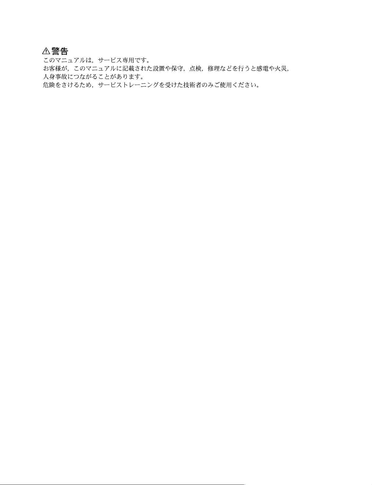
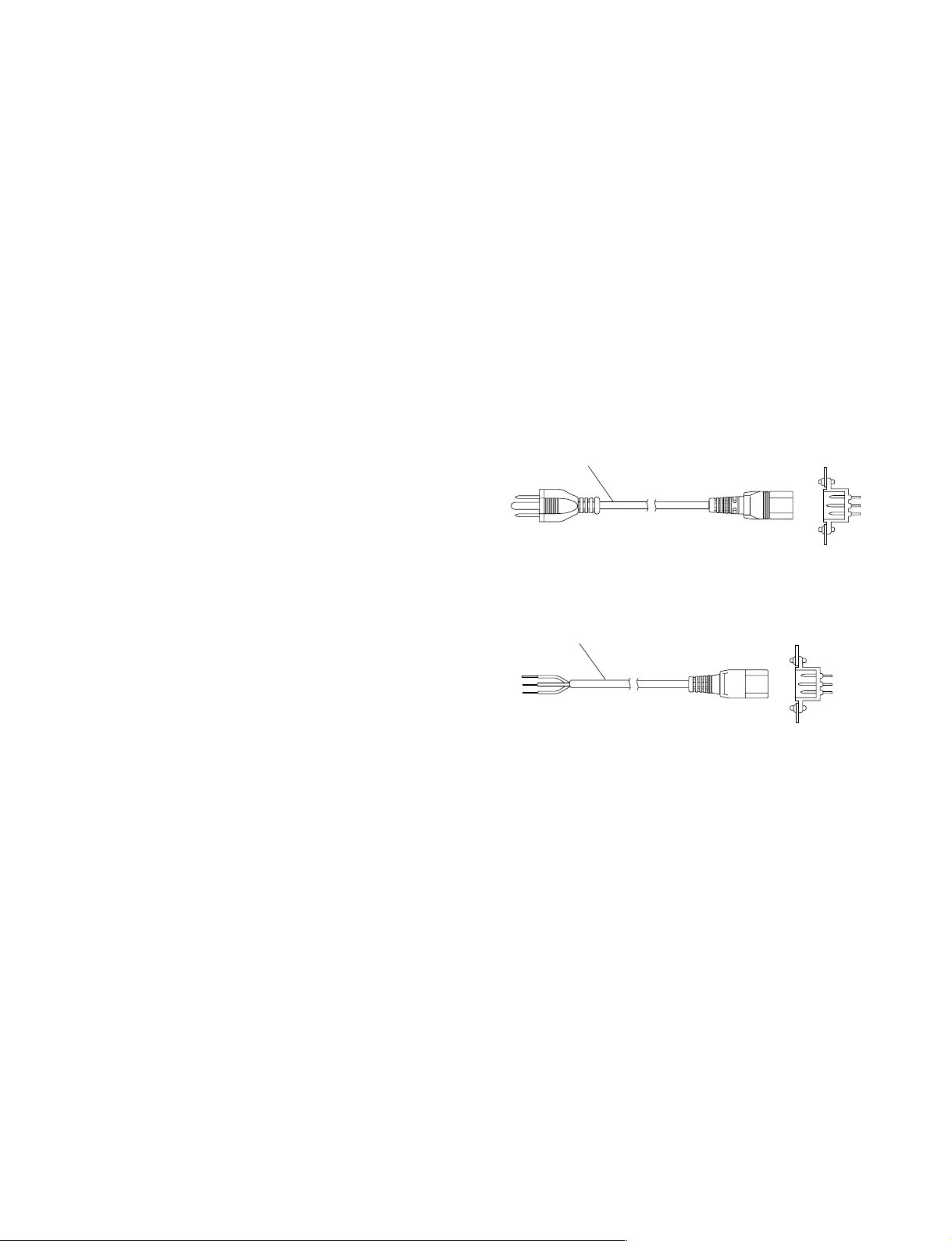
For customers in the U.S.A. and Canada
1 Power cord, 125 V 10 A (2.4 m) : ! 1-557-377-11
AC inlet
1
Installation
1-1. Operating Environment
Operating guaranteed temperature : +5 dC to +40 dC
Performance guaranteed temperature : +10 dC to +35 dC
Operating humidity : 10 % to 90 %
Storage temperature : _20 dC to +60 dC
Mass : Approx. 18 kg
(with all options
installed)
Prohibited locations for installation
. Areas where the unit will be exposed do direct sunlight
or any other strong lights.
. Dusty areas
. Areas is subject to vibration.
. Areas with strong electric or magnetic fields.
. Areas near heat sources.
. Areas subject to electrical noise.
. Areas subject to static electricity.
Ventilation
The inside of the DCU-8000 is cooled by a fan (both sides
on the rear).
The power supply can be damaged if the exhaust vent
(both sides on the rear) and air intake (front panel) are
blocked or the fan is stopped.
Therefore, leave a blank space of more than 10 cm in the
front and back of the DCU-8000.
1-2-2. Recommended Power Cord
w
. The power cord is not supplied with the DCU-8000.
Be sure to use the power cord that is applicable to places
in the area.
To avoid a fire or an electric shock, be sure to use the
designated power cord.
. Do not damage the power cord a otherwise fire or
electric shock may result.
For customers in the all Europian countories
1 Power cord, 250 V 10 A (2.4 m) : ! 1-782-929-21
1
AC inlet
1-2. Power Supply
1-2-1. Power Specifications
A switching regulator is used for the power supply of this
unit. A voltage within the range of 100 V to 240 V can be
used without changing the supply voltage.
Power requirements : AC 100 to 240 V ± 10 %
Power frequency : 50/60 Hz
Current consumption : Maximum 1.4 A
n
As the inrush current at turn-on is a maximum 20 A (at 100
V)/60 A (at 230 V), the capacity of the AC power must be
commensurate with this source load.
If the capacity of the AC power is not adequately large, the
AC power source breaker will operate or the unit will
abnormally operate.
DCU-8000 IM
1-1
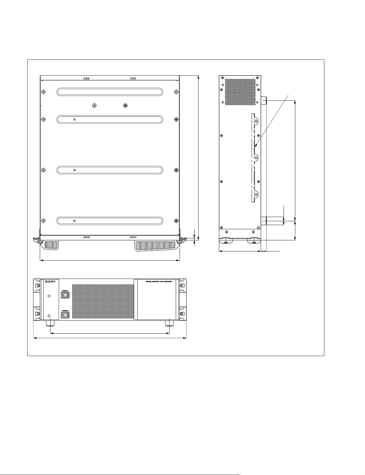
1-3. Installation Space (External dimensions)
1-3. Installation Space (External dimensions)
Rack mount metal
(supplied with RMM-10)
440
375
482
520
7
132.4
17.5
380
ø26
61
1-2
Unit : mm
DCU-8000 IM

1-4. Installing the Options
The DCU-8000 is shipped from the factory with the necessary options (refer to the following table)
already installed in the MKS-8700, in accordance with the specified system configuration.
DCU-8000 Options
Model name Structure
Plug-in board Connector board
MKS-8701 Tally/GPI Output Board RC-90 board CN-2195 board
MKS-8702 Serial Interface Board IF-848 board CN-2194 board
HK-PSU03 Backup Power Supply Unit _
1-4. Installing the Options
DCU-8000 IM
1-3
 Loading...