

Page 1
© 2014 Sony Corporation
Printed in Japan
Operating Instructions
Before operating the unit, please read this manual thoroughly and retain it for
future reference.
LSPX-W1
4-535-453-11 (2)
Video Projector
Page 2
WARNING
To reduce the risk of fire or electric
shock, do not expose this apparatus
to rain or moisture.
To avoid electrical shock, do not open
the cabinet. Refer servicing to
qualified personnel only.
WARNING
THIS APPARATUS MUST BE
EARTHED.
WARNING
When installing the unit, incorporate a
readily accessible disconnect device in the
fixed wiring, or connect the power plug to an
easily accessible socket-outlet near the unit.
If a fault should occur during operation of
the unit, operate the disconnect device to
switch the power supply off, or disconnect
the power plug.
For the customers in the U.S.A.
This equipment has been tested and found to
comply with the limits for a Class B digital
device, pursuant to part 15 of the FCC Rules.
These limits are designed to provide
reasonable protection against harmful
interference in a residential installation. This
equipment generates, uses and can radiate
radio frequency energy and, if not installed
and used in accordance with the instructions,
may cause harmful interference to radio
communications. However, there is no
guarantee that interference will not occur in
a particular installation. If this equipment
does cause harmful interference to radio or
television reception, which can be
determined by turning the equipment off and
on, the user is encouraged to try to correct
the interference by one or more of the
following measures:
- Reorient or relocate the receiving antenna.
- Increase the separation between the
equipment and receiver.
- Connect the equipment into an outlet on a
circuit different from that to which the
receiver is connected.
- Consult the dealer or an experienced
radio/TV technician for help.
You are cautioned that any changes or
modifications not expressly approved in this
manual could void your authority to operate
this equipment.
All interface cables used to connect
peripherals must be shielded in order to
comply with the limits for a digital device
pursuant to Subpart B of part 15 of FCC
Rules.
If you have any questions about this product,
you may call;
Sony Customer Information Service Center
1-800-222-7669 or http://www.sony.com/
Declaration of Conformity
Trade Name: SONY
Model: LSPX-W1
Responsible party: Sony Electronics Inc.
Address: 16530 Via Esprillo,
San Diego, CA 92127
U.S.A.
Telephone Number:858-942-2230
This device complies with part 15 of the
FCC Rules. Operation is subject to the
following two conditions: (1) This device
may not cause harmful interference, and
(2) this device must accept any interference
received, including interference that may
cause undesired operation.
Caution
Use of controls or adjustments or
performance of procedures other than those
specified herein may result in hazardous
radiation exposure.
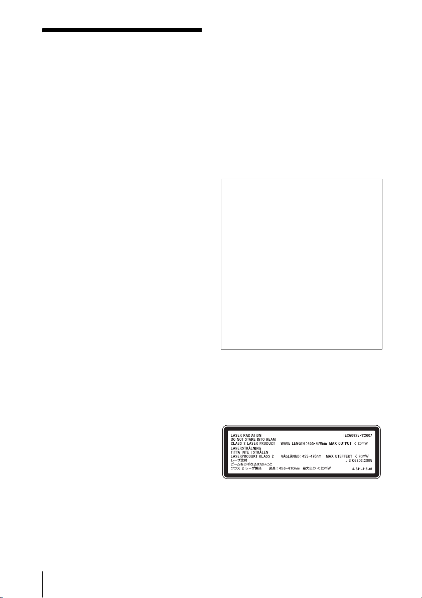
This Video Projector is classified as a
CLASS 2 LASER PRODUCT.
This CLASS 2 LASER PRODUCT label is
located beside the projection window of the
Video Projector.
2
Page 3

This label is located beside the projection
window of the Video Projector.
3
Page 4

Table of Contents
Precautions ......................................... 6
Notes on Installation and Usage ........ 7
Carrying the unit .......................... 7
Unsuitable installation .................. 7
Unsuitable Conditions ..................8
Location of Controls
Front ................................................... 9
Rear/Bottom ..................................... 11
Remote Control ................................ 12
Connections and
Preparations
Checking the Supplied
Accessories ................................... 13
Inserting the Batteries into the Remote
Control .......................................... 13
Connecting the AC Power Cord ....... 14
Installing the Unit ............................ 15
Adjusting the Projection Image ....... 15
Attaching the Bottom Covers ...........20
Attaching the Terminal Door ...........21
Connecting to Video Equipment or a
Computer ...................................... 22
Connecting the Exclusive
Speakers ........................................ 24
Projecting
Projecting the Picture .......................25
Turning Off the Power ................25
Watching 3D Video Images ..............26
Using the 3D Glasses ..................26
Using the Picture Position ................27
Selecting the Aspect Ratio According to
the Video Signal ............................28
Selecting the Picture Viewing
Mode .............................................30
Using the Menus
Operation through the Menus ...........31
Picture Menu ....................................33
Advanced Picture Menu ...................38
Screen Menu .....................................39
Setup Menu .......................................41
Function Menu .................................43
Installation Menu ..............................45
Information Menu .............................48
About the Preset Memory ...........48
Using Network Features
Displaying the Control Window of the
Unit with a Web Browser ..............49
Operating the Control Window ........50
Switching the Page ......................50
Setting the Access Limitation .....50
Confirming the Information
Regarding the Unit ..................50
4
Table of Contents
Page 5

Error Handling
Troubleshooting ...............................51
About Indicators ...............................54
Message Lists ...................................56
Others
Updating the Software .....................57
About x.v.Color ................................57
About the Simulated 3D Feature ......58
Cleaning ...........................................58
Specifications ...................................60
Preset Signals .............................61
Input Signals and Adjustment/
Setting Items ...........................63
Compatible 3D Signals ...............64
3D Signals and Adjustment/
Setting Items ...........................64
Aspect Mode ...............................66
Storage Conditions of Adjustment/
Setting Items ...........................66
Installation Distance and Projection
Image Size ....................................68
Dimensions .......................................71
NOTICES AND LICENCES
FOR SOFTWARE USED IN THIS
PRODUCT ....................................73
Index .................................................88
Table of Contents
5
Page 6

Precautions
On safety
• Check that the operating voltage of your
unit is identical with the voltage of your
local power supply.
• Should any liquid or solid object fall into
the cabinet, unplug the unit and have it
checked by qualified personnel before
operating it further.
• Unplug the unit from the wall outlet if it is
not to be used for several days.
• To disconnect the cord, pull it out by the
plug. Never pull the cord itself.
• The wall outlet should be near the unit and
easily accessible.
• The unit is not disconnected to the AC
power source (mains) as long as it is
connected to the wall outlet, even if the
unit itself has been turned off.
• Do not look into the lens while in use.
• Do not place your hand or objects near the
ventilation holes. The air coming out is
hot.
On preventing internal heat buildup
After you turn off the power with the ?/1
(ON/STANDBY) button, do not disconnect
the unit from the wall outlet while the
cooling fan is still running.
Caution
This unit is equipped with ventilation holes
(intake/exhaust). Do not block or place
anything near these holes, or internal heat
build-up may occur, causing picture
degradation or damage to the unit.
On repacking
Save the original shipping carton and
packing material; they will come in handy if
you ever have to ship your unit. For
maximum protection, repack your unit as it
was originally packed at the factory.
On watching 3D video images
Safety precautions
• You should only use the 3D glasses for
watching 3D video images.
• If you observe flickering or flashing, turn
off the lighting in the room.
• Not for use by children without proper
adult supervision.
• Be careful not to pinch your fingers in
hinges of the 3D glasses when bending the
temple frames.
• Do not drop or modify these 3D glasses.
• If these glasses are broken, keep broken
pieces away from your mouth or eyes.
On inspection of light source
related parts
Since the unit uses a laser, when performing
maintenance or inspection of light source
related parts, particular attention and a safe
environment are necessary. Be sure to
consult with qualified Sony personnel
(charged).
On LCD Projector
The LCD projector is manufactured using
high-precision technology. You may,
however, see tiny black points and/or bright
points (red, blue, or green) that continuously
appear on the LCD projector. This is a
normal result of the manufacturing process
and does not indicate a malfunction.
Also, when you use multiple LCD projectors
to project onto a screen, even if they are of
the same model, the color reproduction
among projectors may vary, since color
balance may be set differently from one
projector to the next.
On condensation
If the room temperature where the projector
is installed changes rapidly, or if the
projector is moved suddenly from a cold to a
warm place, condensation in the projector
may occur. As the condensation may cause
malfunction, be careful in adjusting
temperature settings of the air conditioner. If
condensation occurs, leave the projector
turned on for about four hours before use.
6
Precautions
Page 7
SONY WILL NOT BE LIABLE FOR
DAMAGES OF ANY KIND
RESULTING FROM A FAILURE TO
IMPLEMENT PROPER SECURITY
MEASURES ON TRANSMISSION
DEVICES, UNAVOIDABLE DATA
LEAKS RESULTING FROM
TRANSMISSION SPECIFICATIONS,
OR SECURITY PROBLEMS OF ANY
KIND.
Notes on Installation and Usage
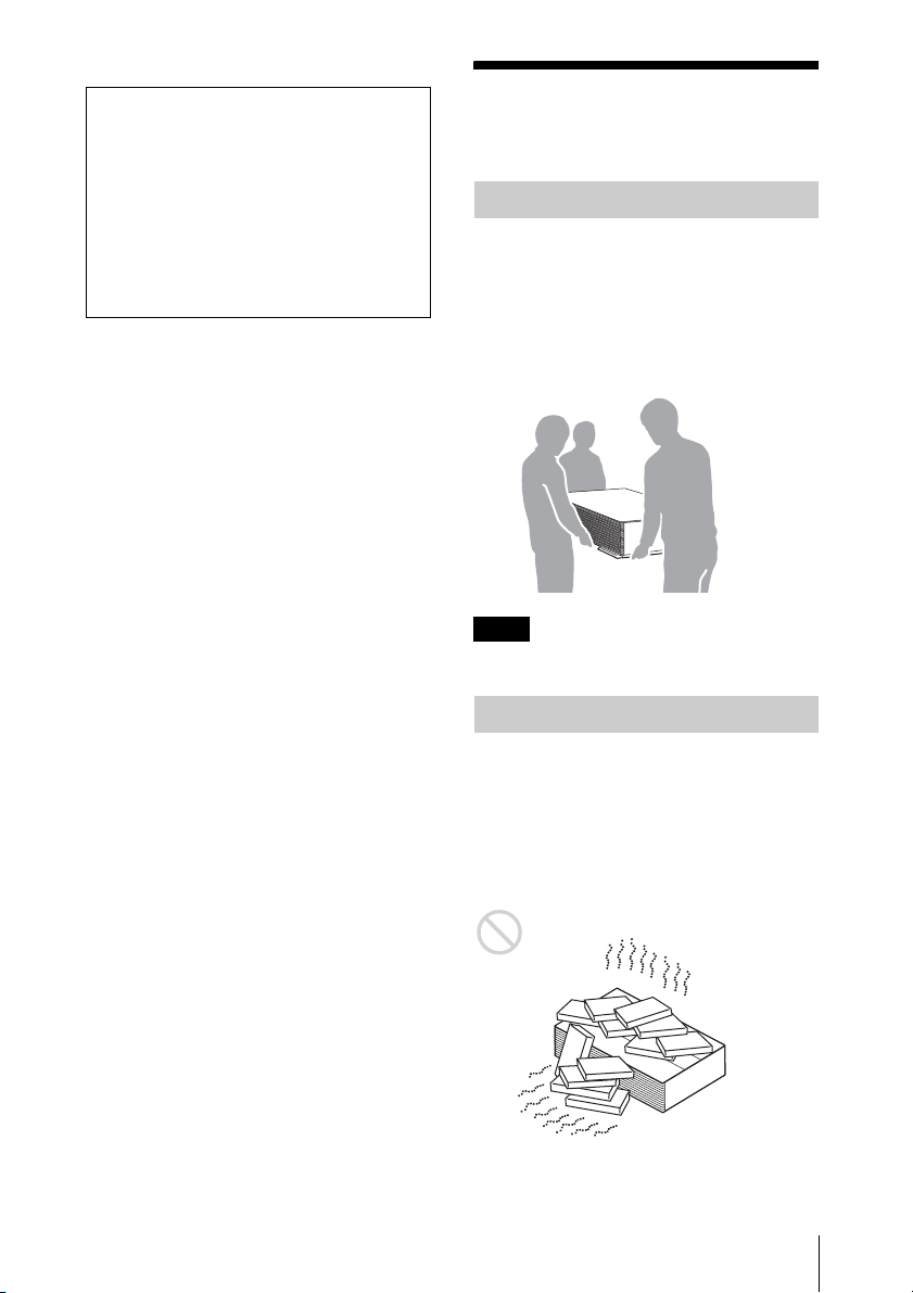
Carrying the unit
When carrying the unit, be sure to use three
or more people - one person for each side
and one person for the front side as in the
below illustration.
When holding the bottom of the unit, hold it
firmly by placing your hand under the inner
part as much as possible.
Note
Be sure not to grasp the control panel part.
Unsuitable installation
Do not place the unit in the following
situations, which may cause malfunction or
damage to the unit.
Poorly ventilated location
Leave space of more than 30 cm (11
inches) from the top or front of the unit.
Notes on Installation and Usage
7
/8
7
Page 8
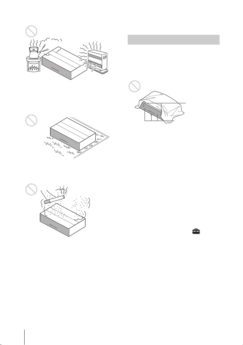
Hot and humid
On a long fluffy carpet
There are the ventilation holes on the bottom
of the unit. It may cause a malfunction if the
the ventilation holes are blocked.
Very dusty and extremely smoky
locations
• If there is debris, sand, etc. in the legs of
the unit, the floor may be damaged.
Unsuitable Conditions
Do not do any of the following while using
the unit.
Blocking the ventilation holes (intake
or exhaust)
Ventilation holes
(exhaust)
Ventilation holes
(intake)
Tilting front/rear and left/right
Do not install the unit anywhere other than
on a level surface. Installing the unit in such
a location may result in uneven color
uniformity or reduce the reliability of the
effects of the light.
If the unit is installed with inclining back
and forth, the picture shape on the projection
surface is trapezoidal. Install the unit so that
the unit and projection surface are arranged
in parallel.
Other Note
• Air from air conditioners or the ventilation
holes of this unit or other devices, may
cause oscillation on the projection surface.
Be sure not to install this unit in the area
where the air from air conditioners or the
ventilation holes of these devices reach to
the lens part of this unit.
• The top cover of the projector opens and
closes. If you place something beside the
unit, place it at a distance more than 1 mm
from the unit.
8
Notes on Installation and Usage
When installing the unit at high
altitudes
When using the unit at an altitude of
1,500 m (approx. 4,900 ft) or higher, set
“Cooling Setting” on the Setup menu to
“High”. Failing to set this mode when using
the unit at high altitudes could have adverse
effects, such as reducing the reliability of
certain components.
Page 9
Location of Controls
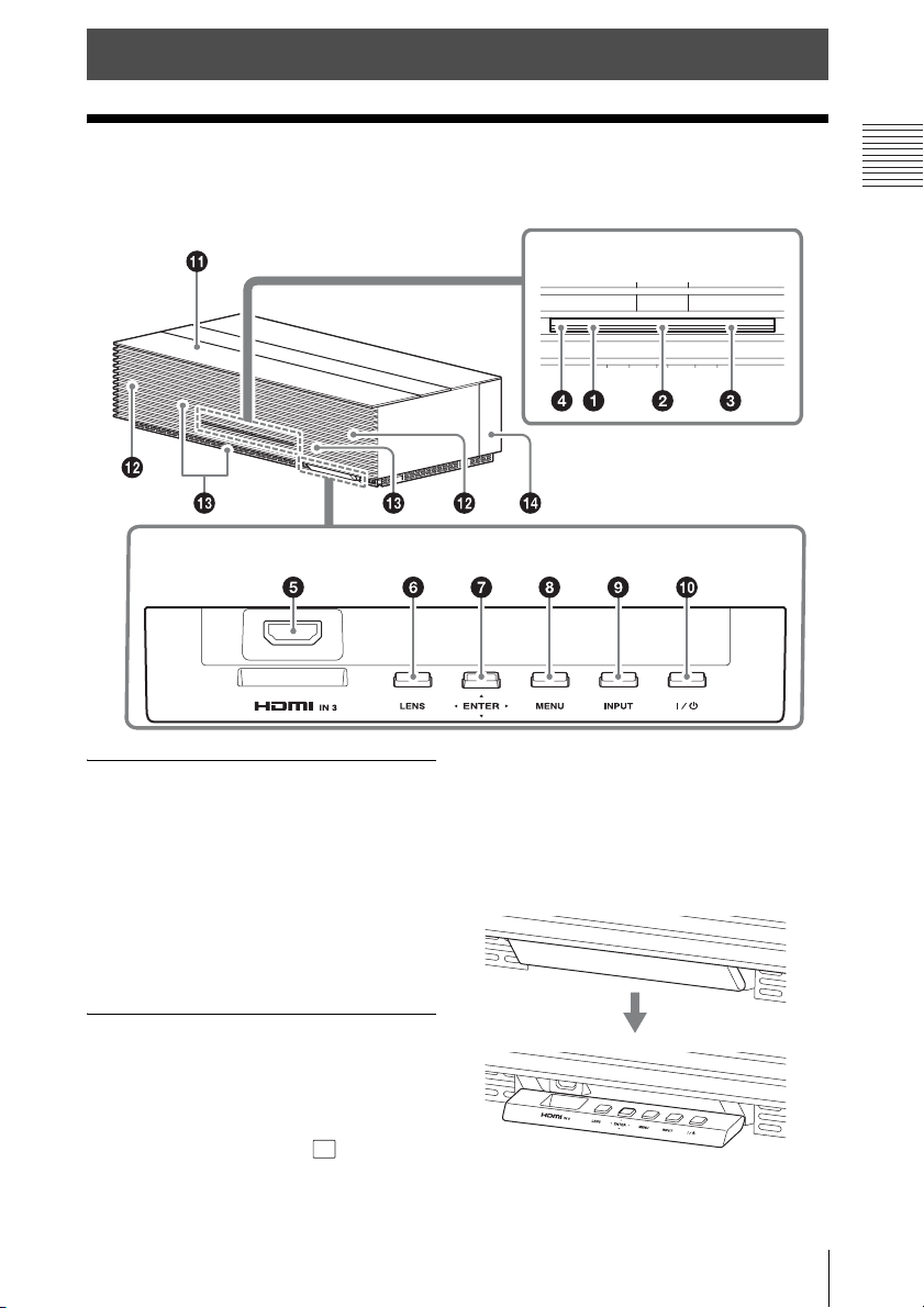
Front
The buttons on the control panel function the same as those on the remote control.
Control panelConnector
Indicators and remote control
detector
a WARNING1 indicator (page 54)
b LED indicator (page 16)
c WARNING2 indicator (page 54)
i INPUT button (page 25)
j ?/1 (ON/STANDBY) button
(page 16)
Tip
The door opens by pulling the side of the door.
Location of Controls
d Remote control detector
(page 15)
Connector and control panel
e HDMI 3 connector (page 22)
f LENS button (page 15)
g M/m/</, (arrow)/ (enter)
button (page 31)
h MENU button (page 31)
Front
9
Page 10

Others
k Top cover (page 16)
Opens automatically when the unit is
turned on, and closes automatically
when the unit is turned off.
l Ventilation holes (exhaust)
m Ventilation holes (intake)
n Terminal door (page 21)
Note
The top cover of the projector opens and
closes. If you place something on the top
cover, it may fall and break or cause a
malfunction.
If you look through the projection window
(lens) while the unit is projecting, the light
may damage your eyes. Take special caution
when using the unit around children.
10
Front
Page 11
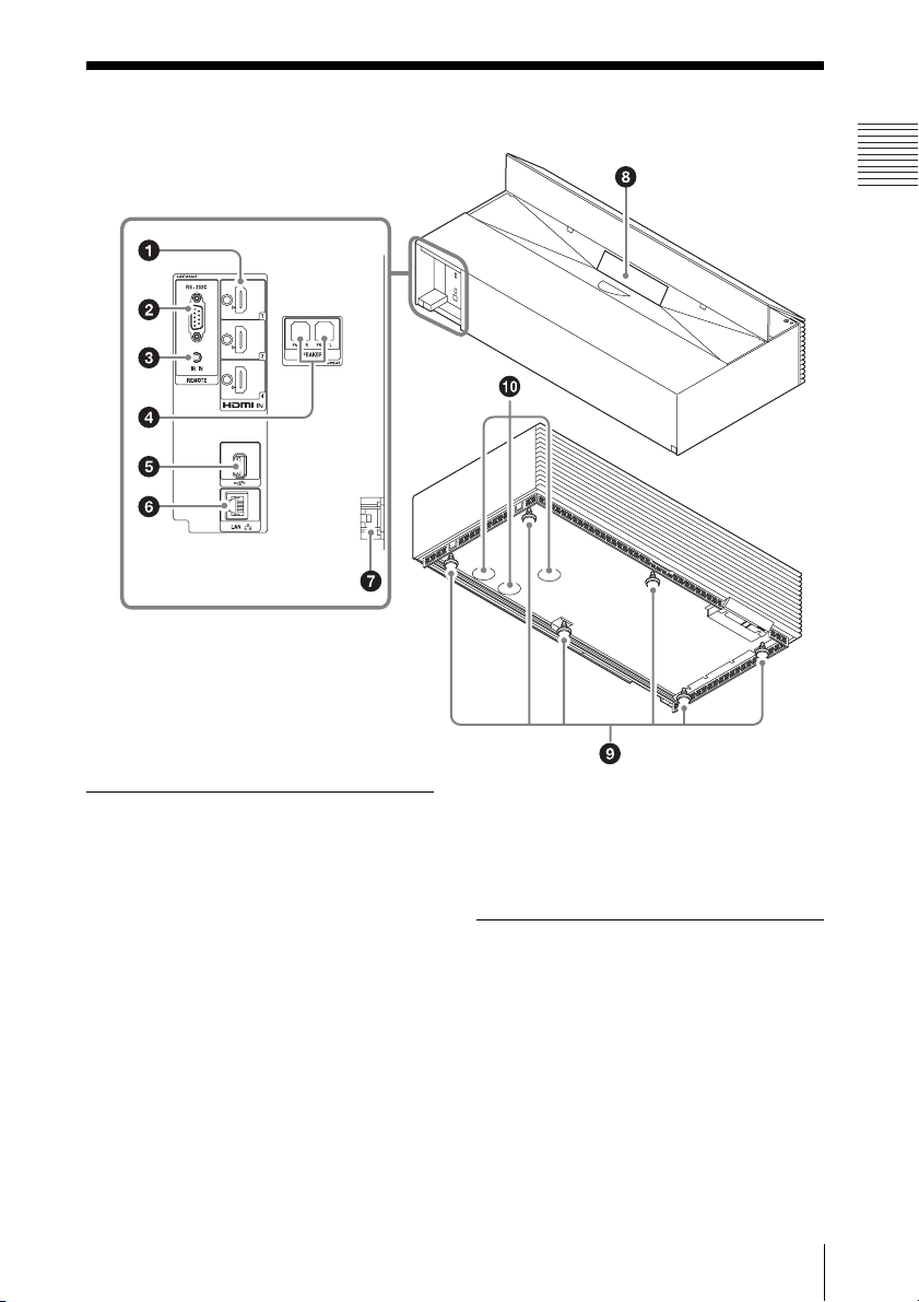
Rear/Bottom
Location of Controls
Connectors
a HDMI 1/HDMI 2/HDMI 4
connector (page 22)
b REMOTE connector
Connects to a system for remote control,
etc.
c IR IN connector
Inputs signals to control the unit.
d Speaker connector (page 24)
e USB connector (page 57)
f LAN connector (page 49)
CAUTION
For safety, do not connect the connector for
peripheral device wiring that might have
excessive voltage to this port. Follow the
instructions for this port.
Others
g AC IN socket (page 14)
h Projection window (lens)
Projects a video from this window.
i Feet (adjustable) (page 20)
j Ventilation holes (intake)
Rear/Bottom
11
Page 12
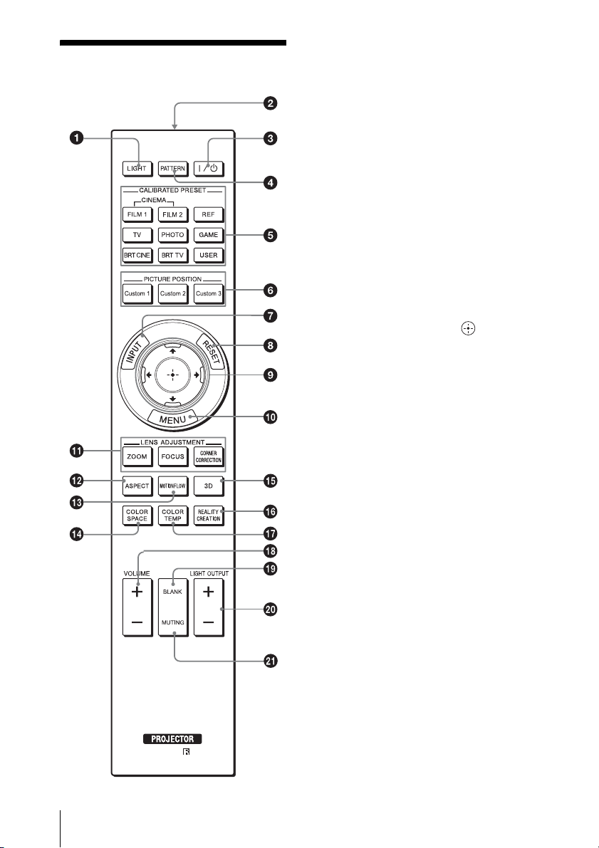
Remote Control
a LIGHT button
Illuminates the buttons on the remote
control.
b Infrared transmitter
c ?/1 (ON/STANDBY) button
(page 16)
d PATTERN button (page 16)
e CALIBRATED PRESET buttons
(page 30)
f PICTURE POSITION button
(page 27)
g INPUT button (page 25)
h RESET button (page 32)
i M/m/</, (arrow)/ (enter)
buttons (page 31)
j MENU button (page 31)
k LENS ADJUSTMENT buttons
(page 17)
l ASPECT button (page 28)
12
m MOTIONFLOW button (page 35)
n COLOR SPACE button (page 37)
o 3D button (page 26)
p REALITY CREATION button
(page 34)
q COLOR TEMP button (page 35)
r VOLUME +/– button (page 44)
s BLANK button
Turns the video off temporarily. To turn
on, press this button again,
t LIGHT OUTPUT +/– button
(page 34)
u MUTING button
Turns the audio off temporarily. To turn
on, press this button again.
Remote Control
Page 13
Connections and Preparations
This section describes how to install the unit, how to connect the equipment from which you
want to project a picture, etc.
Checking the Supplied Accessories
Check the carton to make sure it contains the
following items:
• Remote control RM-PJ26 (1)
• Size AA (R6) manganese batteries (2)
• AC power cord (1)
•Plug holder (1)
• Bottom cover (front, large) (1)
• Bottom cover (front, small) (1)
• Bottom covers (side) (2)
• Terminal door (1)
• Adjustment tool (1)
• Operating Instructions (this manual) (1)
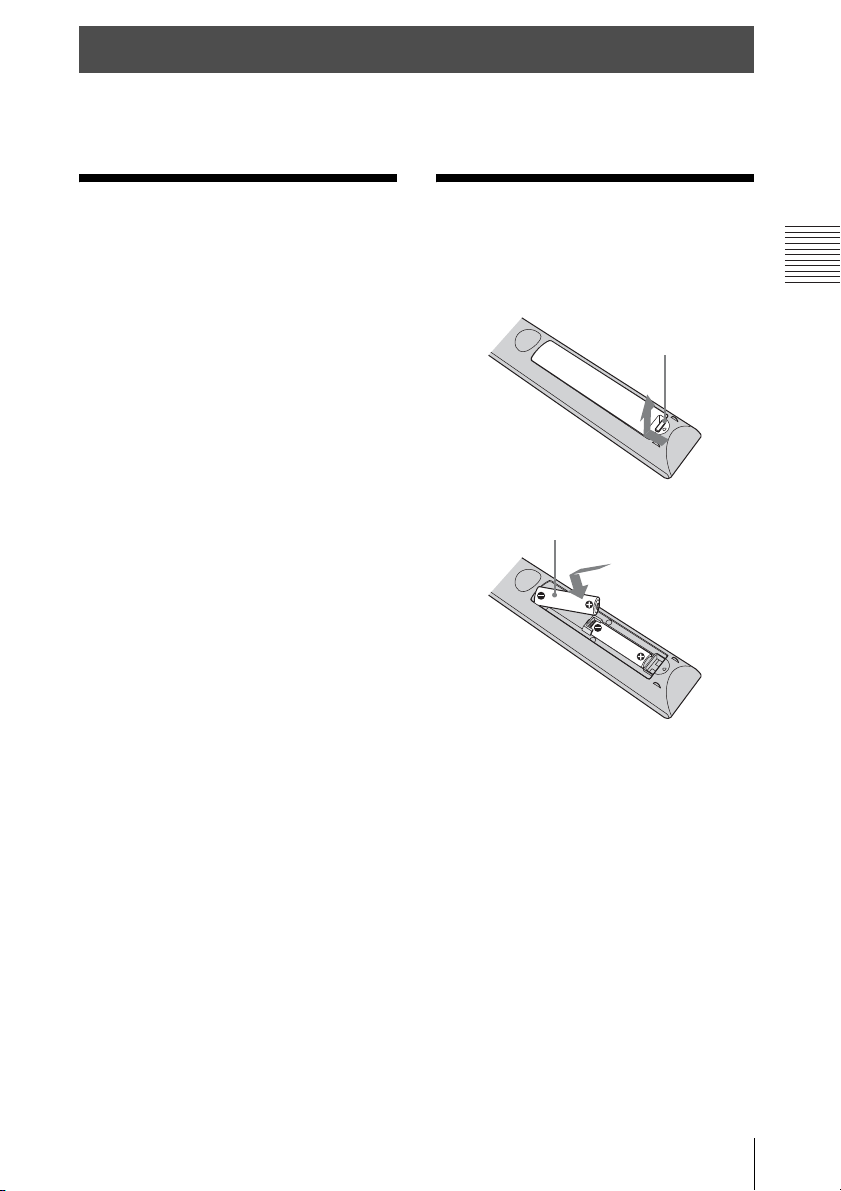
Inserting the Batteries into the Remote Control
Push and slide to
open.
Insert the batteries E
side first.
CAUTION
Danger of explosion if battery is incorrectly
replaced.
Replace only with the same or equivalent
type recommended by the manufacturer.
When you dispose of the battery, you must
obey the law in the relative area or country.
Connections and Preparations
Installing batteries
Two size AA (R6) batteries are supplied for
Remote Control.
To avoid risk of explosion, use size AA (R6)
manganese or alkaline batteries.
Checking the Supplied Accessories / Inserting the Batteries into the Remote
13
Page 14
Caution about handling the remote
control
• Handle the remote control with care. Do
not drop or step on it, or spill liquid of any
kind onto it.
• Do not place the remote control in a
location near a heat source, a place subject
to direct sunlight, or a damp room.
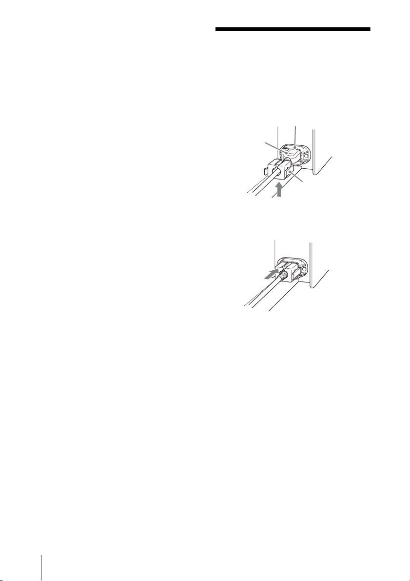
Connecting the AC Power Cord
1 Plug the AC power cord into the AC
IN socket, then attach the plug holder
to the AC power cord.
AC IN socket
AC power cord
(supplied)
Plug holder
(supplied)
2 Slide the plug holder over the AC
power cord to fix to the unit.
14
Connecting the AC Power Cord
Page 15
Installing the Unit
Adjusting the
The installation distance between the unit
and a projection surface varies depending on
the projection size and whether or not you
use the zoom features. Install this unit so that
it fits the desired projection size.
For details on the distance between the unit
and the projection surface (the projection
distance) and the size of projected video, see
“Installation Distance and Projection Image
Size” (page 68).
1 Position the unit so that the unit is
parallel to the projection surface.
Top view
Projection surface
2 Project an image on the projection
surface and adjust the picture so that it
fits the projection surface (page 15).
Notes
• When using a projection surface with an
uneven surface, stripes may rarely appear on
the projection surface depending on the
distance between the projection surface and
the unit or the zooming magnifications. This
is not a malfunction of the unit.
• The projection picture may be distorted if the
projection surface is not flat.
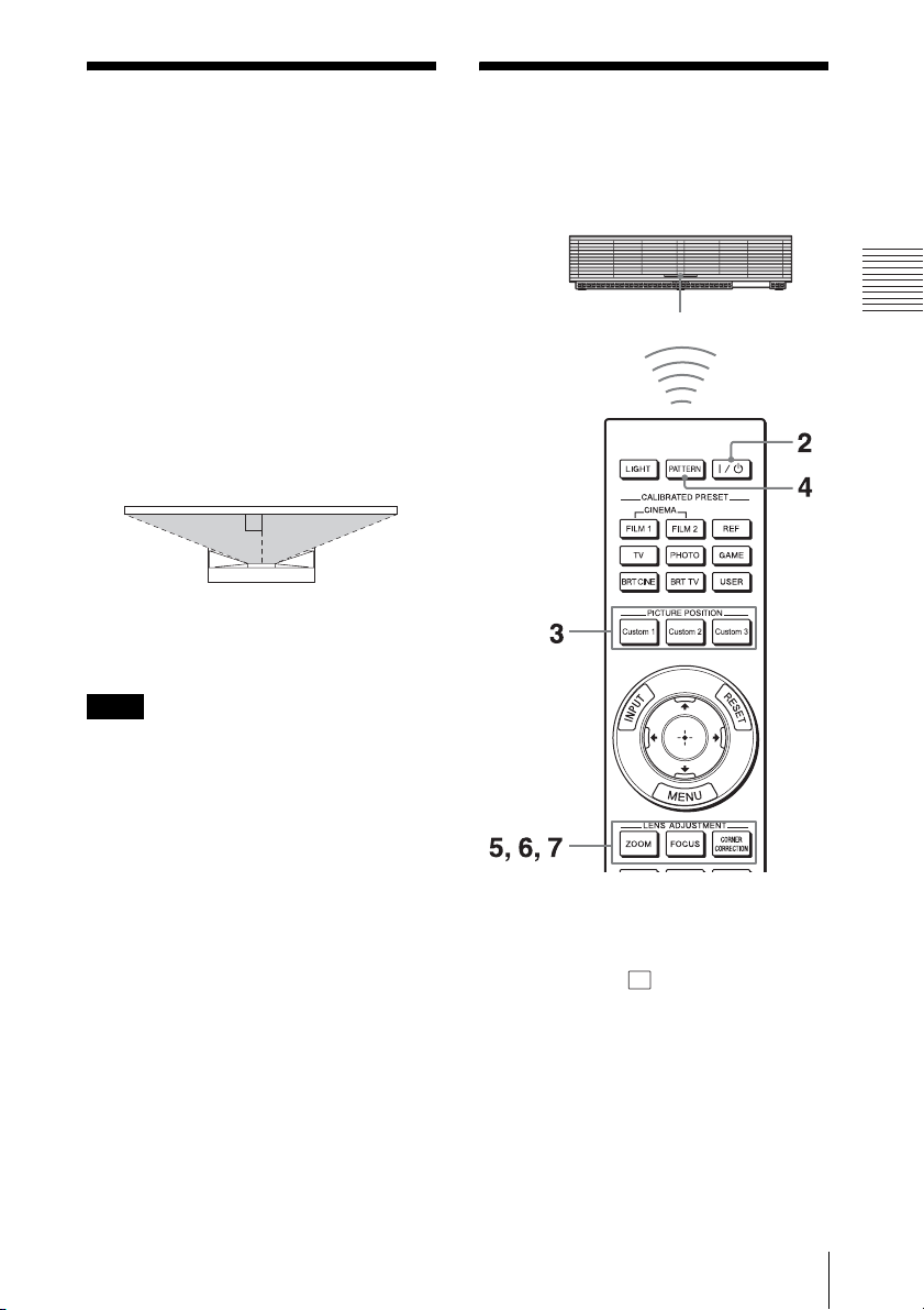
Projection Image
Project an image on the projection surface
and then adjust the projection image.
Remote control detector
Connections and Preparations
Tips
?/1 (ON/STANDBY), INPUT, MENU,
• The
and M/m/</,/ (joystick) buttons on
the front panel of the unit function the same
as those on the remote control. The LENS
button functions in the same way as the
LENS ADJUSTMENT (ZOOM, FOCUS,
CORNER CORRECTION) buttons of the
remote control.
Installing the Unit / Adjusting the Projection Image
15
Page 16
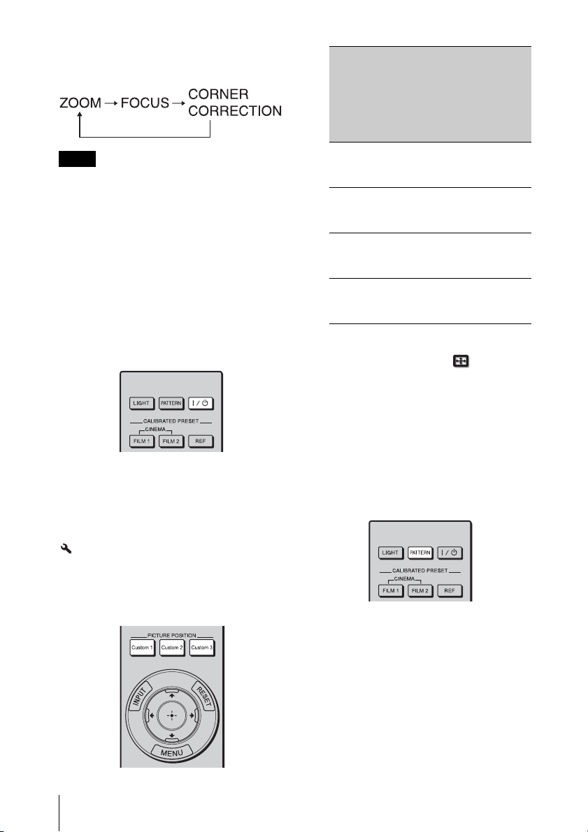
• When adjusting the lens, each time you press
the LENS button on the unit, the lens
adjustment function switches as follows.
Note
Depending on the installation location of the
unit, you may not be able to control it with the
remote control. In this case, point the remote
control at the remote control detector of the
unit.
1 After connecting the AC power cord to
the unit, plug the AC power cord into
a wall outlet.
The unit goes into standby mode.
2 Press the ?/1 (ON/STANDBY) button
to turn on the unit.
Image size
(for
maximum
zoom)
147- to
132-inch
132- to
121-inch
121- to
113-inch
113- to
106-inch
* Approximate adjustment value. When
the setting is overwritten in “Picture
Position” of the Screen menu
(page 39), it cannot be returned to the
default setting.
Installation
distance
(from a
projection
surface to
the rear of
the unit)
11 to 17 cm
(4.3 to 6.7
inches)
6 to 11 cm
(2.4 to 4.3
inches)
3 to 6 cm
(1.2 to 2.4
inches)
0 to 3 cm
(0 to 1.2
inches)
Destination
for
adjustment*
PICTURE
POSITION
Custom 1
PICTURE
POSITION
Custom 2
PICTURE
POSITION
Custom 3
Default
setting
To perform further adjustment or change
the image size by using the zoom
function, follow the steps 3 to 6.
The top cover opens.
The LED indicator lights in white.
Tip
The LED indicator does not light when
“Illumination” is set to “Off” on the Installation
menu.
3 Press the PICTURE POSITION
button that matches the projection
size.
16
Adjusting the Projection Image
4 Press the PATTERN button to display
the
lens adjustment window (test
pattern).
To return to the previous screen, press
the PATTERN button again.
Page 17
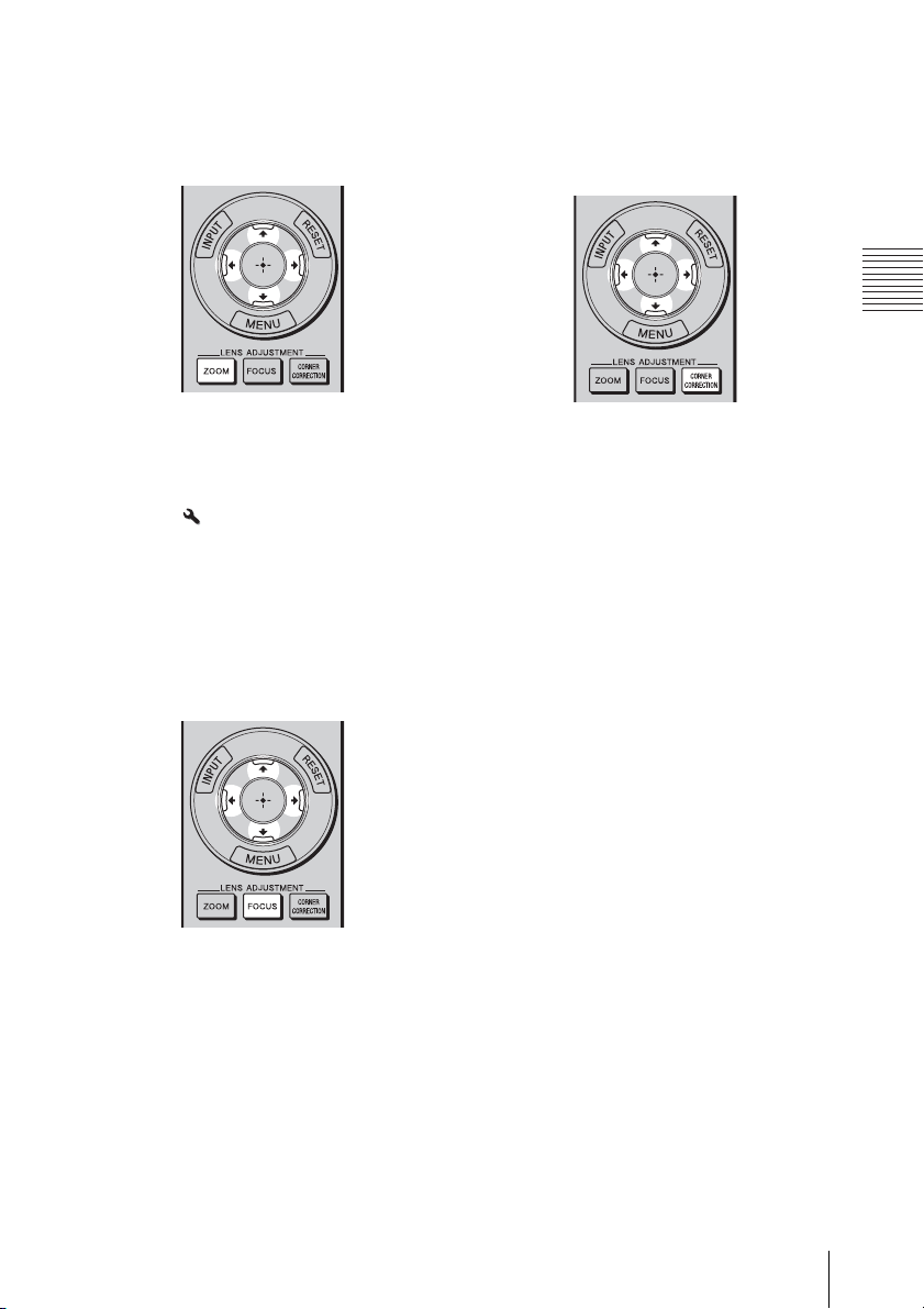
5 Adjust the picture size.
Press the LENS ADJUSTMENT
(ZOOM) button, and adjust the size of
the picture by pressing the M/m/</,
buttons.
To make the picture larger, press M/,.
To make the picture smaller, press m/<.
Tip
When “Lens Control” is set to “Off” on the
Installation menu, you cannot adjust the
picture size, focus or correct the position by
pressing the ZOOM, FOCUS, or CORNER
CORRECTION buttons (page 45).
6 Adjust the focus.
Press the LENS ADJUSTMENT
(FOCUS) button, and adjust the focus of
the center of the picture.
7 Press the LENS ADJUSTMENT
(CORNER CORRECTION) button,
and adjust the focus and distortion on
the top corner of the picture by
pressing the M/m/</, buttons.
Connections and Preparations
When the FOCUS button is pressed after
adjusting the picture size by the ZOOM
button, focus of the center area is
adjusted automatically. For the further
adjusting, use the M/m/</, buttons.
Adjusting the Projection Image
17
Page 18
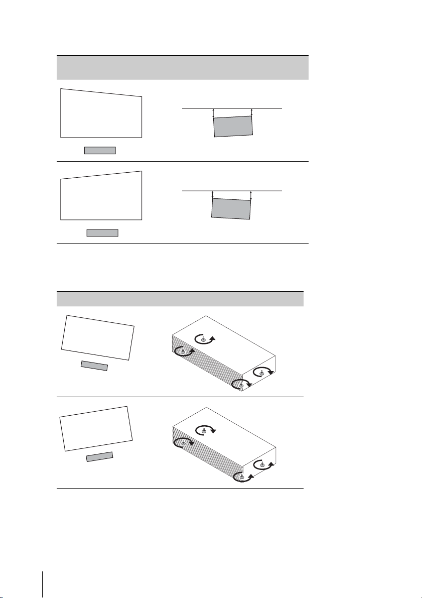
8 Check if the upper side and lower side of the picture are parallel.
If not, install the unit in a position parallel to the projection surface (a=b).
Image distortion Installation state to the projection surface
(Top view)
a
a > b
a
a < b
b
b
9 Check if the lower side of the picture is horizontal.
If not, use the left/right feet (adjustable) to keep the unit level. For details of adjusting the
feet, see page 20.
Image distortion Feet adjustment
18
Adjusting the Projection Image
Page 19
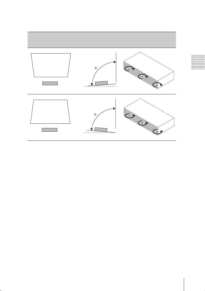
10 Check if the left side and right side of the picture are vertical.
If not, use the foreground feet (adjustable) to keep the unit vertical to the projection
surface. For details of adjusting the feet, see page 20.
Image distortion Installation state to the
11 Repeat steps 5 and 6.
Make the frame of the projection
surface rectangular and parallel to the
floor to finish the installation.
projection surface
Feet adjustment
(Side view)
Connections and Preparations
c > 90°
c < 90°
Adjusting the Projection Image
19
Page 20
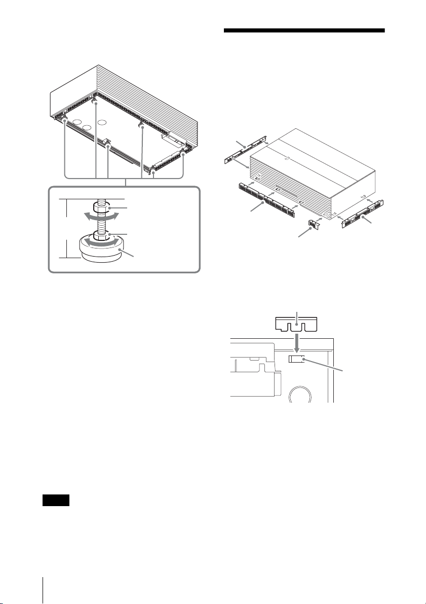
To adjust the feet
You can adjust the height by using the six
feet at the bottom of the unit.
Attaching the Bottom Covers
Attach the bottom covers to the front in two
places and both sides of the unit after
installing the unit.
Bottom cover
(side)
Fixing nut
Foot
height
Adjusting nut
Foot
1 Loosen the fixing nut by turning it to
the left when viewed from the top
.
2 Turn the adjusting nut to adjust the
length of the foot.
Extending: Turn the adjusting nut to the
right (clockwise) when viewed from the
top.
Contracting: Turn the adjusting nut to
the left (counterclockwise) when
viewed from the top.
3 Tighten the fixing nut by turning it to
the right when viewed from the top.
Tips
• Use the supplied adjustment tool for
adjusting the feet.
• The height does not change if you turn the
foot.
Notes
• Be careful not to catch your finger when
turning the fixing nut or adjusting nut.
• You can adjust the foot height up to 60 mm.
If the foot height is more than 70 mm, the
foot may come off and the unit may drop
causing an injury.
Bottom cover
(front, large)
Bottom cover
(front, small)
Bottom
cover
(side)
Insert the tab of the bottom cover into the
hole at the bottom of the unit.
Ta b
Hole
Bottom of the unit
20
Attaching the Bottom Covers
Page 21
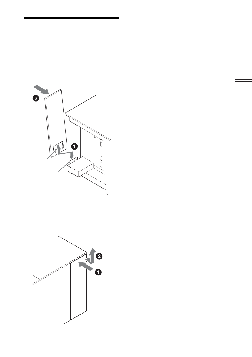
Attaching the Terminal Door
Insert the opening of the terminal door into
the groove on the rear of the unit 1, then
push the upper part in 2. The upper part of
the door attaches to the magnet on the unit
and door is closed.
Opening
Groove
Connections and Preparations
To remove the terminal door
Push the upper part of the door until it clicks
1, then pull it out and upward after opening
the upper part 2.
Attaching the Terminal Door
21
Page 22
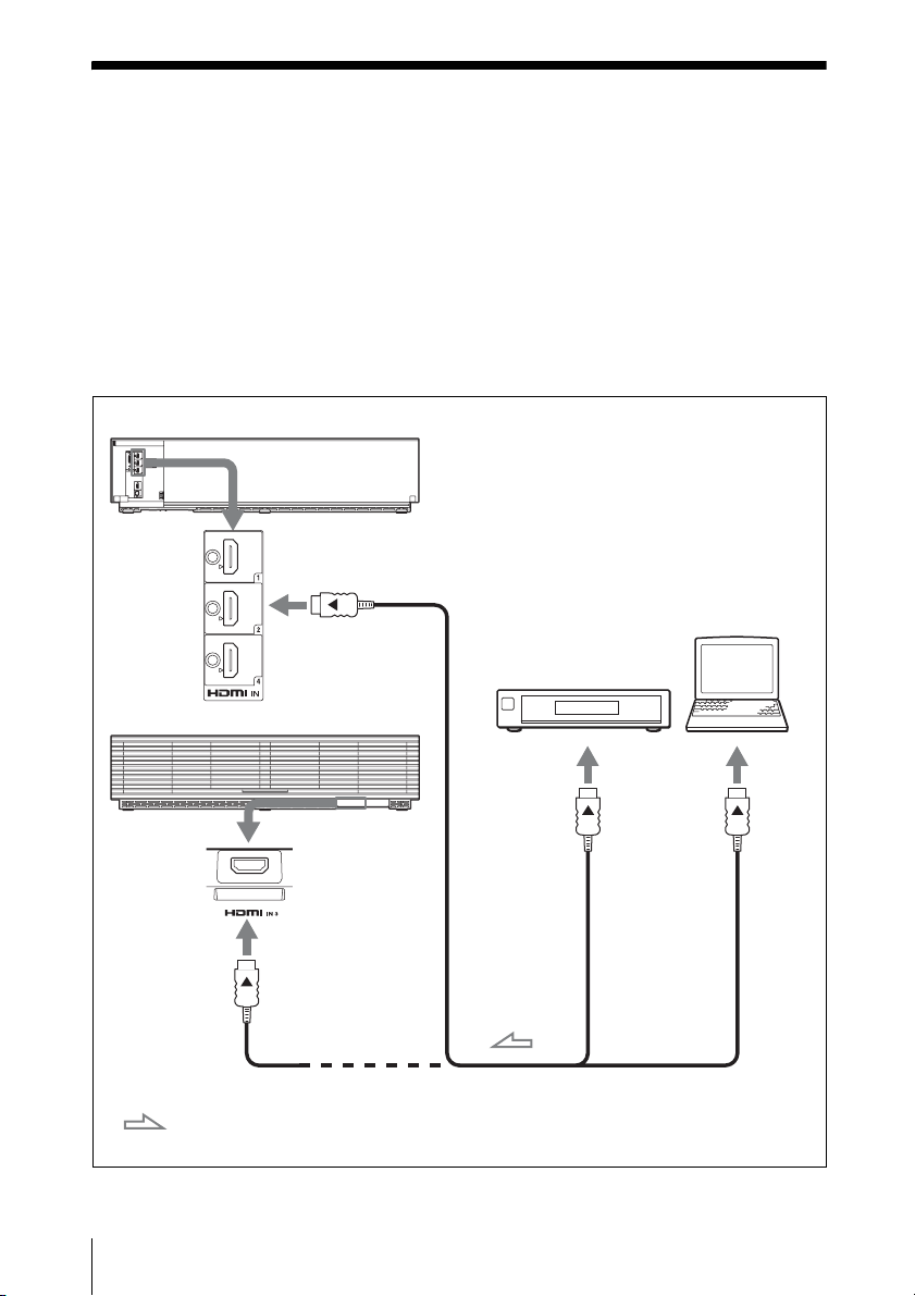
Connecting to Video Equipment or a Computer
You can enjoy high picture quality by connecting a DVD player/recorder, Blu-ray Disc player/
recorder, or PlayStation
®
equipped with HDMI output to the HDMI input of the unit.
When making connections, be sure to do the following:
• Turn off all equipment before making any connections.
• Use the proper cables for each connection.
• Insert the cable plugs properly; poor connection at the plugs may cause a malfunction or poor
picture quality. When pulling out a cable, be sure to pull it out from the plug, not the cable
itself.
• Refer to the operating instructions of the connected equipment.
Rear of the unit
Computer
Equipment with HDMI
output connectors
Front of the unit
to HDMI
output
: Video signal flow Use a high-speed HDMI cable on which the cable type logo
22
Connecting to Video Equipment or a Computer
HDMI cable (not supplied)
is specified. (Sony products are recommended.)
Page 23

Notes
• Use a high-speed HDMI cable. With a standard HDMI cable, images of 1080p, DeepColor, 3D
video and 4K video may not be displayed properly.
• When connecting an HDMI cable to the unit, make sure the
input of the unit and the v mark on the connector of the cable are faced at each other.
• If the picture from equipment connected to the unit with an HDMI cable is not correct, check the
settings of the connected equipment.
• If you set your computer to output the signal to both the computer’s display and this equipment,
the picture of the equipment may not appear properly. Set your computer to output the signal to
only the external monitor. For details, refer to the operating instructions supplied with your
computer. For settings of the computer, consult with the manufacturer of the computer.
V mark on the upper part of the HDMI
Connections and Preparations
Connecting to Video Equipment or a Computer
23
Page 24
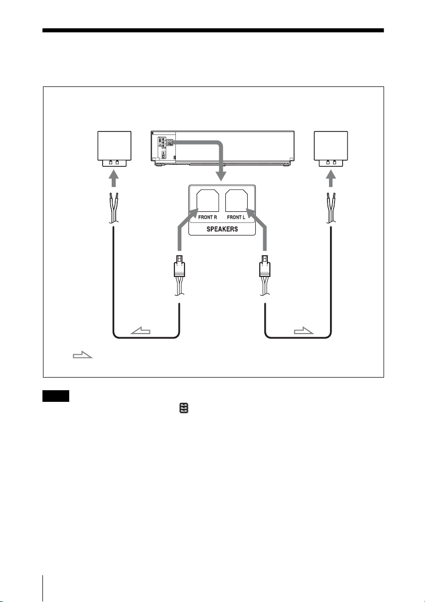
Connecting the Exclusive Speakers
You can output the sound that is input to the unit from the exclusive speakers, and enjoy the
sound.
Speaker
(right)
: Audio signal flow
Note
Set “Speaker” to “On” on the Function menu to output the sound from the speakers.
Rear of the unit
Speaker cord
Speaker cord
Speaker
(left)
24
Connecting the Exclusive Speakers
Page 25
Projecting
This section describes how to operate the unit to view a picture from the equipment connected
to the unit. It also describes how to adjust the quality of the picture to suit your taste.
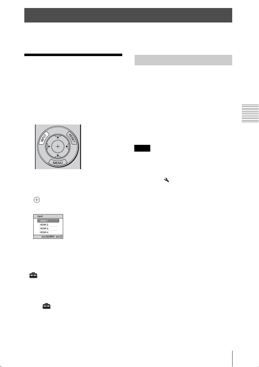
Projecting the Picture
1 Turn on both the unit and the
equipment connected to the unit.
2 Press INPUT to display the input
palette on the projection surface.
3 Select the equipment from which you
want to display images.
Press INPUT repeatedly or press M/m/
(enter) to select the equipment from
which to project.
Turning Off the Power
1 Press the ?/1 (ON/STANDBY)
button.
The message “POWER OFF?” appears.
2 Press the ?/1 (ON/STANDBY) button
again before the message disappears.
The top cover closes automatically, the
fan stops, and the LED indicator turns
off.
You can disconnect the AC power cord.
Notes
• Never disconnect the AC power cord while
the unit is turned on.
• The LED indicator does not change when
“Illumination” is set to “Off” on the
Installation menu,
• It may take several minutes to turn the LED
indicator off after the top cover is closed due
to the adjusting of the unit.
You can turn off the unit by holding the ?/1
(ON/STANDBY) button for about 1 second,
instead of performing the above steps.
Projecting
Example: To view the picture from the
video equipment connected to the HDMI
1 connector of this unit.
Tips
• When “Status” is set to “Off” on the Setup
menu, the input palette does not appear.
Press the INPUT button to switch between
input terminals sequentially.
• You can change the language for the menu
and on-screen displays in “Language” on the
Setup menu (page 41).
Projecting the Picture
25
Page 26

Watching 3D Video Images
You can enjoy powerful 3D video images,
such as from 3D games and 3D Blu-ray
Discs, using the optional Active 3D Glasses
(TDG-BT500A).
Adjusting/Setting the 3D functions
You can adjust/set the 3D functions by
pressing the 3D button on the remote control
or with the “3D Settings” of the Function
menu. For details, see “3D Settings”
(page 43).
Using the 3D Glasses
1 Turn on the HDMI equipment for 3D
compatibility connected to the unit,
then play the 3D content.
For details on how to play 3D content,
refer to the operating instructions for the
connected equipment.
2 Turn on the unit and project the 3D
video image.
For details on how to project the image,
see “Projecting the Picture” (page 25).
3 Turn on the 3D glasses, and then put
them on so that they fit comfortably.
For details on how to use the 3D glasses,
see “Using the 3D Glasses” (page 26).
Tips
• The factory default setting for “2D-3D
Display Sel.” is “Auto” to allow projecting
3D video images automatically when the unit
detects 3D signals.
• To convert 3D video images to 2D video
images, set “2D-3D Display Sel.” to “2D”
(page 43).
Notes
• It may not be possible to display 3D video
image, depending on the type of signal. Set
the “2D-3D Display Sel.” to “3D,” and “3D
Format” to “Side-by-Side” or “Over-Under”
to suit the format of the 3D content you want
to watch (page 43).
• Use the 3D glasses within the
communication range (page 26).
• There are differences in perception of 3D
video images among individuals.
• When the temperature of the usage
environment is low, the 3D effect may be
diminished.
1 Turn on the 3D glasses, and register
them on the unit.
For details on how to register the 3D
glasses, refer to the operating
instructions supplied with the 3D
glasses.
2 Put on the 3D glasses.
Precautions for use
Misoperation may occur if:
• The viewing position is too far from the
projector
• There are other communication devices,
such as a wireless LAN (IEEE802.11 b/g/
n) or a microwave with a bandwidth of 2.4
GHz, near the unit
3D glasses communication range
The following figure indicates the
communication range of the 3D glasses. If
you try to watch 3D video images from a
distance greater than the communication
range or install the unit outside the
communication range, the 3D glasses may
not be able to display the images properly.
Also, the distance varies depending on the
environment of the room and installation
environment of the unit.
26
Watching 3D Video Images
Page 27
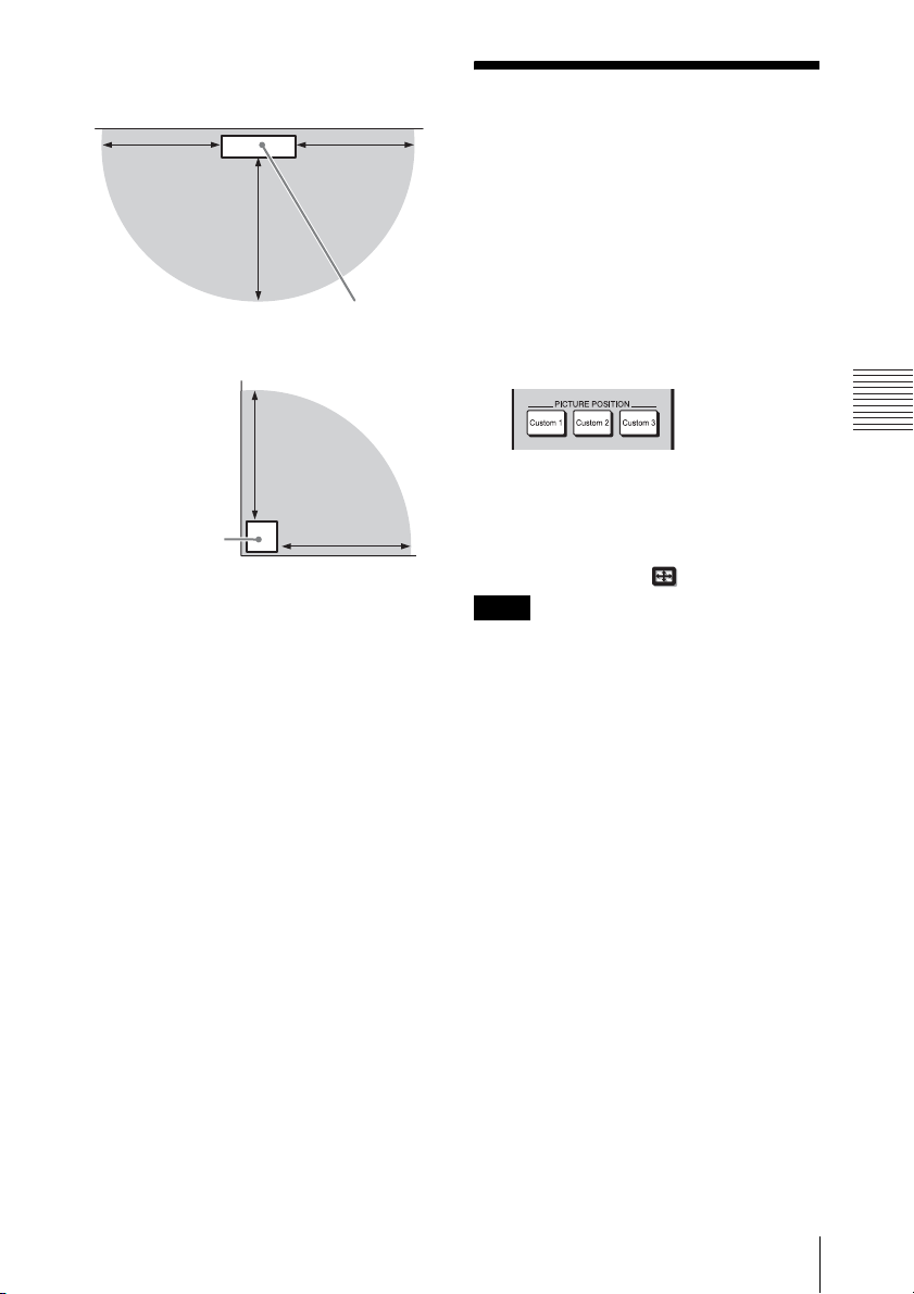
Top view
10 m
(33 ft)
Projection surface
10 m
(33 ft)
10 m
(33 ft)
Using the Picture Position
You can recall the stored lens settings (lens
zoom, lens focus, lens corner correction) and
aspect ratio.
Use this function for changing projection
image size of multiple pictures, etc.
Side view
Projection
surface
Projector
10 m
(33 ft)
Projector
10 m
(33 ft)
1 Press one of the PICTURE
POSITION [Custom 1], [Custom 2],
and [Custom 3] buttons.
The picture position that you pressed is
recalled.
Tip
Store or delete the lens settings in the “Picture
Position” of the Screen menu (page 39).
I
Notes
• If you press any button on the remote control
or the unit while the lens is moving, the lens
stops. In this case, select the lens position
again or adjust the lens manually.
• The Picture Position function is not
guaranteed to reproduce the lens settings
precisely.
• When you use the subtended angle of two or
more aspects using lens zoom, install the unit
within the specified parameters referring to
“Installation Distance and Projection Image
Size” (page 68).
Projecting
Using the Picture Position
27
Page 28
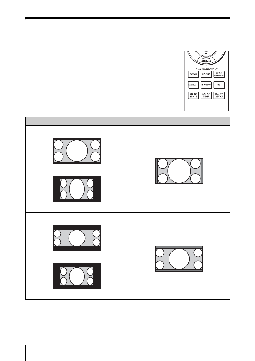
Selecting the Aspect Ratio According to the Video Signal
You can select an aspect ratio best suited for
the video signal received.
Press ASPECT.
Each time you press the button, you can
select the “Aspect” setting.You can also
select it using the menu (page 40).
Original image (for 16:9 display) Recommended setting and resultant images
1.85:1
ASPECT
button
1.85:1 Zoom
Squeezed 1.85:1
2.35:1
Squeezed 2.35:1
28
Selecting the Aspect Ratio According to the Video Signal
2.35:1 Zoom
Page 29

Original image (for 16:9 display) Recommended setting and resultant images
Normal
1.78:1 (16:9)
1.33:1 (4:3)
1.33:1 (4:3) with side panels
Stretch
Squeezed
Projecting
Notes
• Selectable aspect modes vary depending on
the input signal (page 66).
• The aspect cannot be selected when a
computer signal is input, a signal with a
resolution of 4096 × 2160 is input (page 61),
or “V Keystone” is set to other than “0” on
the Installation menu.
Notes on switching the “Aspect”
setting
• Select the aspect mode taking into account
that changing the aspect ratio of the
original picture will provide a different
look from that of the original image.
• Note that if the unit is used for profit or for
public viewing, modifying the original
picture by switching the aspect may
constitute an infringement of the rights of
authors or producers, which are legally
protected.
Selecting the Aspect Ratio According to the Video Signal
29
Page 30

Selecting the Picture Viewing Mode
You can select the picture viewing mode that
best suits the type of video source or room
conditions.
You can save and use different preset modes
for 2D/3D respectively.
Press one of the CALIBRATED PRESET
buttons.
Setting items Description
CINEMA FILM 1 Picture quality suited to reproducing the highly dynamic and
clear images typical of master positive film.
CINEMA FILM 2 Picture quality suited to reproducing the rich tone and color
typical of a movie theater, based on the tones changed for FILM
1.
REF A picture quality setup suitable for when you want to reproduce
faithfully the original image quality, or for enjoying image
quality, without any adjustment.
TV Picture quality suited for watching TV programs, sports,
concerts, and other video images.
PHOTO Ideal for projecting still images taken with a digital camera.
GAME Picture quality suited to gaming, with well-modulated colors
and fast response.
BRT CINE Picture quality suited for watching movies in a bright
environment, such as a living room.
BRT TV Picture quality suited for watching TV programs, sports,
concerts, and other video images in a bright environment, such
as a living room.
USER Adjusts the picture quality to suit your taste then saves the
setting. The factory default setting is the same as “REF.”
CALIBRATED
PRESET buttons
30
Selecting the Picture Viewing Mode
Page 31

Using the Menus
This section describes how to make various adjustments and settings using the menus.
Operation through the Menus
The unit is equipped with an on-screen menu
for making various adjustments and settings.
If you select an item name followed by an
arrow (B), the next menu window with
setting items appears.
1 Press MENU.
The menu window appears.
2 Press M/m to select a menu item, and
press , or .
3 Press M/m to select an item you want
to set or adjust and press , or .
Using the Menus
The setting items are displayed in a popup menu, in a setting menu, in an
adjustment menu or in the next menu
window.
Pop-up menu
Setting items
The items that can be set or adjusted
with the selected menu appear. The item
presently selected is shown in white.
Operation through the Menus
31
Page 32

Setting menu
Adjustment menu
Next menu window
Setting items
4 Make the setting or adjustment of an
item.
To reset the picture that has been
adjusted
Select “Reset” from the Picture menu.
When the screen display appears, select
“Yes” using < and press .
All of the following settings are reset to its
factory preset value:
“Reality Creation,” “Cinema Black Pro,”
“Motionflow,” “Contrast,” “Brightness,”
“Color,” “Hue,” “Color Temp.,”
“Sharpness,” and “Expert Setting” on the
Picture menu
To reset the items that have been
adjusted
Select an item in the menu screen, and
display the pop-up menu, the setting menu,
or the adjustment menu.
Press RESET on the remote control to reset
only the selected settings to its factory preset
value.
Note
The RESET button on the remote control is
available only when the adjustment menu or
the setting menu is selected.
When changing the adjustment
level
To increase the value, press M/,.
To decrease the value, press m/<.
Press to store the setting and restore
the original menu screen.
When changing the setting
Press M/m to change the setting.
Press to restore the original screen.
You can restore the original screen using
< depending on the selected item.
To clear the menu
Press MENU.
32
Operation through the Menus
Page 33

Picture Menu
The Picture menu is used for adjusting the picture.
Note
These items may not be available, depending on the type of input signal. For details, see “Input
Signals and Adjustment/Setting Items” (page 63).
Item names in brackets represent those printed on the remote control.
Setting items Description
Calib. Preset
[CALIBRATED
PRESET]
You can select the picture viewing mode that best suits the type of video
source or the environment.
You can save and use different preset modes for 2D/3D respectively.
Cinema Film 1: Picture quality suited to reproducing the highly
dynamic and clear images typical of master positive film.
Cinema Film 2: Picture quality suited to reproducing the rich tone and
color typical of a movie theater, based on the tones changed for Cinema
Film 1.
Reference: A picture quality setup suitable for when you want to
reproduce faithfully the original image quality, or for enjoying image
quality, without any adjustment.
TV: Picture quality suited for watching TV programs, sports, concerts,
and other video images.
Photo: Ideal for projecting still images taken with a digital camera.
Game: Picture quality suited to gaming, with well-modulated colors and
fast response.
Bright Cinema: Picture quality suited for watching movies in a bright
environment, such as a living room.
Bright TV: Picture quality suited for watching TV programs, sports,
concerts, and other video images in a bright environment, such as a
living room.
User: You can adjust the picture quality to suit your taste, and save the
setting. The factory default setting is the same as “Reference.”
Tip
Any adjustments to picture quality settings are saved for each input.
Using the Menus
Picture Menu
33
Page 34

Setting items Description
Reset Resets all currently selected Calib. Preset mode settings to their default
Reality Creation
[REALITY
CREATION]
Cinema Black Pro
Laser Light
Setting [LIGHT
OUTPUT]
Contrast Enhancer Corrects the level of bright and dark parts automatically to optimize
values (page 32).
Tip
Reset does not affect settings saved for the Custom 1 to 5 items of
“Color Temp.”
Adjusts the detail and noise processing of images. (Super-resolution
function)
On: Adjusts the settings of “Reality Creation.”
Database: Select “Normal” or “Mastered in 4K.”
“Mastered in 4K” provides image quality suitable for Blu-ray Disc™
“Mastered in 4K” released by Sony Pictures Home Entertainment.
This setting is available when inputting the 1080/24p signal.
Resolution: When you increase the setting value, the texture and detail
of the picture become sharper.
Noise Filtering: When you increase the setting value, the noise
(picture roughness) becomes less prominent.
Test: On/Off: Switches “On” and “Off” at a certain frequency to
check the effect of “Reality Creation.”
Tip
The display position of the status during the test works together with
the “Menu Position” setting (page 41).
Off: The “Reality Creation” function is not applied.
Dynamic Control: Adjusts the range of movement of the laser light
control.
Full: Automatically optimizes the laser light control and signal
processing according to the brightness level of the input source. This
results in a bright and high contrast image.
Limited: Suppresses the movement and brightness of the laser light
control, making the picture quality suitable for viewing in a dark room.
Off: The “Dynamic Control” function is not applied.
Output: The higher the setting, the brighter the picture. The lower the
setting, the darker the picture.
You can adjust by the LIGHT OUTPUT +/– button on the remote
control.
Tip
After adjusting “Output,” set “Dynamic Control” according to the
brightness of the room and the picture itself.
contrast according to a scene.
Increases image sharpness and makes image dynamic.
High/Middle/Low: You can adjust the contrast enhancer.
Off: The contrast enhancer function is not applied.
34
Picture Menu
Page 35

Setting items Description
Motionflow
[MOTIONFLOW]
Contrast Adjusts the contrast.
Brightness Adjusts the brightness of the picture.
Color Adjusts the color density.
Hue Adjusts the color tone.
Color Temp.
[COLOR TEMP]
Sharpness Sharpens the outline of the picture, or reduces the noise.
Smooth High: Provides smoother picture movement; especially
effective for film-based content.
Smooth Low: Provides smoother picture movement for standard use.
Impulse: Reproduces original picture quality. Provides cinema-like
picture, which may flicker.
Combination: Reduces motion blur while maintaining brightness for
high-speed picture content.
True Cinema: Images, such as a movie created in 24 frames per second,
are reproduced at the original framerate.
Off: The “Motionflow” function is not applied.
Tips
• Select “Off” if the selected “Smooth High,” “Smooth Low,” “Impulse,”
“Combination,” or “True Cinema” results in a distorted picture.
• Depending on the picture content, you may not see the effect visually
even if you have changed the settings.
• Only “Off” or “Impulse” is available when a signal with a resolution of
4096 × 2160 or 3840 × 2160 is input.
Higher values increase the sharpness in images, while lower values
decrease the sharpness.
The higher the setting, the brighter the picture. The lower the setting, the
darker the picture.
The higher the setting, the greater the intensity. The lower the setting, the
lower the intensity.
The higher the setting, the more greenish the picture becomes. The lower
the setting, the more reddish the picture becomes.
Adjusts the color temperature.
D93: Equivalent to 9,300 K color temperature normally used in TVs.
Gives white colors a blue tint.
D75: Equivalent to 7,500 K color temperature used as an ancillary
standard illuminant. Gives a neutral tint between “D93” and “D65.”
D65: Equivalent to 6,500 K color temperature used as a standard
illuminant. Gives white colors a red tint.
D55: Equivalent to 5,500 K color temperature used as an ancillary
standard illuminant. Gives white colors an even redder tint.
Custom 1 to 5: Enables you to adjust, set, and store your favorite color
temperature.
The factory default settings are as follows.
Custom 1: Same as the “D93” color temperature setting.
Custom 2: Same as the “D75” color temperature setting.
Custom 3: Same as the “D65” color temperature setting.
Custom 4: Same as the “D55” color temperature setting.
Custom 5: Setting that prioritizes brightness.
The higher the setting, the sharper the picture. The lower the setting, the
softer the picture, thus reducing the noise.
Using the Menus
Picture Menu
35
Page 36

Setting items Description
Expert Setting
NR (Noise
Reduction)
MPEG NR
(MPEG Noise
Reduction)
Smooth Gradation Smooths the gradation of the flat parts of images.
Film Mode According to the film source you have selected, make a setting for
Gamma
Correction
Reduces the roughness or noise of the picture.
Auto: Detects the noise level to reduce the roughness or noise of the
picture automatically.
High/Middle/Low: Select a setting according to the roughness or noise
of the input signal source.
Off: The NR (noise reduction) function is not applied.
Tip
The noise level may not be detected accurately with “Auto” depending
on the input signal source. If the picture is unacceptable with “Auto,”
select a setting from among “High,” “Middle,” “Low” or “Off.”
Reduces block noise and mosquito noise, particularly in digital signals.
Auto: Detects the noise level to reduce the block noise and mosquito
noise of the picture automatically.
High/Middle/Low: Select a setting according to the block noise and
mosquito noise of the input signal source.
Off: The MPEG NR (MPEG noise reduction) function is not applied.
Tip
The noise level may not be detected accurately with “Auto” depending
on the input signal source. If the picture is unacceptable with “Auto,”
select a setting from among “High,” “Middle,” “Low” or “Off.”
High/Middle/Low: You can adjust the smooth gradation effect.
Off: The smooth gradation function is not applied.
playback.
Auto: Suitable for reproducing the original picture movement.
Normally, set this to “Auto.”
Off: Plays back the picture in progressive format without detecting
video signals automatically.
Adjusts the response characteristics of the tone of the picture.
Select a favorite tone from 10 options.
1.8: Bright Produces a brighter picture overall.
2.0
2.1
2.2
2.4
2.6: Dark Produces a darker picture overall.
Gamma 7: Simulates the gamma curve of film.
Gamma 8: Increases the sharpness in images. Select this when you
watch in a bright environment, such as a living room.
Gamma 9: Produces a brighter picture than Gamma 8.
Gamma 10: Increases the sharpness in images. Select this when you
watch TV programs, etc., in a bright environment, such as a living room.
Off: The “Gamma Correction” function is not applied.
36
Picture Menu
Page 37

Setting items Description
Color Correction On: Adjusts Hue, Saturation and Brightness of the selected colors.
Clear White Emphasizes vivid whites.
x.v.Color Set this item when connecting the unit with equipment that supports
Color Space
[COLOR SPACE]
Repeat steps 1 and 2 described below to specify the target color.
1 Press M/m to select “Color Select,” then press </, to select the
color you want to adjust among “Red,” “Yellow,” “Green,” “Cyan,”
“Blue,” and “Magenta.”
2 Press M/m to select “Hue,” “Saturation” or “Brightness,” then adjust
them to suit your taste using </, while watching the projected
picture.
Off: The “Color Correction” effect is not applied.
High/Low: You can adjust the “Clear White” effect.
Off: The “Clear White” effect is not applied.
x.v.Color and playing back an x.v.Color video signal.
On: You can play back an x.v.Color video signal.
Off: The “x.v.Color” function is not applied.
For details on x.v.Color, see “About x.v.Color” (page 57).
Tip
Setting x.v.Color to “On” disables gamma adjustment.
Converts the color space.
BT.709: An ITU-R BT.709 color space, which is used for highdefinition television broadcast or Blu-ray Disc. The color space is
equivalent to sRGB.
Color Space 1: The color space suited for watching TV programs and
video images, such as sports, concerts, etc.
Color Space 2: The color space suited for watching TV programs,
sports, concerts, and other video images in a bright environment, such as
a living room.
Color Space 3: The color space suited for watching movies in a bright
environment, such as a living room.
Custom: You can adjust the color space setting.
Using the Menus
Input Lag
Reduction
Reduces the delay of the display for a video.
On: Reproduces a smooth fast-moving video image with a reduced
sense of afterimage.
Off: Turns the Input Lag Reduction function off.
Tip
When “Input Lag Reduction” is set to “On,” Motionflow, NR, and MPEG
NR cannot be set.
Picture Menu
37
Page 38

Advanced Picture Menu
You can adjust the gaps in color that have occurred after a long period of use.
Setting items Description
Auto Calibration Pre Check: Checks the color difference against the factory default
Notes
• Auto Calibration results in relatively coarse calibration. The color settings are not guaranteed to
be the same as the factory default values.
• While performing “Pre Check” or “Adjust,” the colors are projected automatically. This is not a
malfunction.
• Do not turn off the power or operate the remote control or control panel during “Pre Check” or
“Adjust,” as the process may be canceled.
Tips
• dE is an indicator of changing color. The smaller the value of dE, the fewer the changes caused by
the color.
• Perform the calibration after the power has been on for more than 30 minutes.
• It takes a few minutes for “Pre Check” or “Adjust” to complete.
• When “Pre Check” or “Adjust” starts, the screen position may shift as the lens returns to its factory
default position. After completion, the screen returns to its previous position automatically.
• If the environment, such as the brightness of the room, changes while performing “Pre Check” or
“Adjust”, measurement may be affected.
• If the “Pre Check” or “Adjust” function fails, try it again.
settings, before calibration starts.
Adjust: Performs Auto Calibration.
Before/After: Toggles the factory default settings and the setting after
the calibration at a certain frequency. You can check the effect of the
calibration by monitoring the actual image.
Reset: Resets the calibration results, and returns to the factory default
settings.
38
Advanced Picture Menu
Page 39

Screen Menu
You can set the picture size, aspect mode, etc.
Note
These items may not be available, depending on the type of input signal. For details, see “Input
Signals and Adjustment/Setting Items” (page 63).
Item names in brackets represent those printed on the remote control.
Setting items Description
Picture Position
[PICTURE
POSITION]
You can store up to five combinations of lens settings and aspect ratios.
After setting the lens and aspect, select from “1.85:1,” “2.35:1,”
“Custom 1,” “Custom 2” or “Custom 3” depending on the subtended
screen angle, and after confirming, continue by selecting “Save,”
“Delete,” or “Select.”
Save: Stores the current lens settings (lens zoom, lens focus, lens corner
correction) in the selected position. If a setting is already stored in that
position, it is overwritten.
Delete: Deletes the stored setting. After the setting is deleted, “1.85:1,”
“2.35:1,” “Custom 1,” “Custom 2,” or “Custom 3” in the display changes
to “---.”
Select: Recalls the settings of the selected position.
Tip
The optimal aspect ratio is preset for each picture position. The aspect
ratio can be changed and saved for each picture position.
Notes
• If you press any button on the unit while the lens is moving, the lens
stops. In this case, select the lens position again or adjust the lens
manually.
• When you use a 2.35:1 or a 16:9 subtended angle with the Picture
Position function, make sure that the installation position is suitable
(page 27).
• The Picture Position function is not guaranteed to reproduce the lens
settings precisely.
Using the Menus
Screen Menu
39
Page 40

Setting items Description
Aspect
[ASPECT]
You can set the aspect ratio of the picture to be displayed for the current
input signal (page 28).
1.85:1 Zoom: A 1.85:1 aspect ratio picture is displayed in its original
aspect ratio, enlarged so that black bands do not appear at the top and
bottom of the projection surface.
2.35:1 Zoom: A 2.35:1 aspect ratio picture is displayed in its original
aspect ratio, enlarged so that black bands at the top and bottom of the
projection surface are as small as possible.
Normal: Input video is displayed in its original aspect ratio, enlarged to
fill the projection surface. This mode is suitable for viewing 1.78:1
(16:9) and 1.33:1 (4:3) video.
Stretch: Displays video that has been squeezed to 1.33:1 (4:3) as 1.78:1
(16:9) aspect ratio.
Tips
• Selectable aspect modes vary depending on the input signal (page 66).
• The aspect cannot be selected for an input signal from a computer or an
input signal with a resolution of 4096 × 2160, or when “V Keystone”
on the Installation menu is set to other than 0 (pages 61, 62, 66).
40
Screen Menu
Page 41

Setup Menu
The Setup menu is used to change the factory preset settings, etc.
Setting items Description
Status Sets whether or not the on-screen display is displayed.
Set to “Off” to turn off the on-screen displays except for certain menus,
message when turning off the power, and warning messages.
Language Selects the language used in the menu and on-screen displays. Available
languages are English and Japanese.
Menu Position You can change the position to display the menu on the projection
surface.
Bottom Left: Displays the menu on the bottom left area of the
projection surface.
Center: Displays the menu on the center of the projection surface.
Cooling Setting Sets the unit to operate at the prevailing atmospheric pressure.
High: Use this setting when using the unit at an altitude of 1,500 m
(approx. 4,900 ft) or higher.
Standard: Use this setting when using the unit at normal altitudes.
Tip
When this item is set to “High,” the fan noise becomes slightly louder
since the fan speed increases.
Remote Start Sets the Remote Start settings.
On: You can turn on the power from a PC or a terminal which is
connected to a network.
Off: Turns off the Remote Start function.
Tips
• To use the function, the unit should be connected to the network in
advance (page 47).
• To turn on the power with the Remote Start function, a special
command should be sent from a PC or a terminal. For details, consult
with qualified Sony personnel.
Note
When the Remote Start is set to “On,” the standby power requirement
will increase.
Using the Menus
Setup Menu
41
Page 42

Setting items Description
Power Saving Sets the power saving mode.
Standby: If no signal is input for 10 minutes, power is turned off
automatically and the projector goes into standby mode.
Off: Disables the power saving function.
42
Setup Menu
Page 43

Function Menu
The Function menu is used for changing the settings of the various functions of the unit.
Setting items Description
3D Settings You can change the settings of the 3D function.
2D-3D Display
Sel.
For Switching the video images to “2D” or “3D.”
Auto: Displays 3D video images when HDMI signals with 3D
information* are input. Displays 2D video images when other signals
are input.
3D: Displays 3D video images according to the 3D system selected in
“3D Format.” However, when HDMI signals with 3D information are
input to the unit, displays 3D video images according to the 3D system
of those HDMI signals.
2D: Displays 2D video images.
* The 3D information is additional information to differentiate 3D. Some
HDMI signals have additional information to differentiate 3D and
some HDMI signals have none.
3D Format: Set the 3D system when the input HDMI signals do not
include 3D information.
Simulated 3D: Converts 2D video images to 3D video images. The
setting can be made only for input the HD signals.
The simulated 3D feature may have limited effect, depending on the
video source.
There are differences in perception of 3D video images among
individuals.
Side-by-Side: Select this to display 3D images as two similar images,
side-by-side.
Over-Under: Select this to display 3D images as two similar images,
one above the other.
Tips
• “2D-3D Display Sel.” cannot be set to “3D” for some video sources.
For available 3D signals, see “Compatible 3D Signals” (page 64).
• The simulated 3D feature may have limited effect, depending on the
projection image size (100 to 120 inches recommended) and the video
source.
• The menu display has a ghost while a 3D video image is displayed and
is best viewed with the 3D glasses.
Using the Menus
Function Menu
43
Page 44

Setting items Description
3D Brightness For adjusting the brightness of the picture when watching 3D video
3D Depth Adjust For adjusting the depth of the 3D video images on the projection surface.
Simulated 3D
Effect
Dynamic Range Sets the video input level for HDMI 1, 2, 3, and 4 connectors.
Vo l u m e
[VOLUME]
Speaker When you select “On,” the sound is output from the supplied speakers.
images.
You can select the brightness from “High” or “Standard.”
The setting can be made only when a 3D Format other than “Simulated
3D” is selected.
Depth
NormalFront Depth
We recommend that “3D Depth Adjust” be set to “0.” The 3D video
images may be difficult to perceive, depending on the setting of “3D
Depth Adjust.”
For adjusting the 3D effect when 2D content is converted to 3D video
images. You can select the effect from among “High,” “Middle,” and
“Low.”
Tip
There are differences in perception of 3D video images converted by the
simulated 3D function among individuals.
Auto: Sets the video input level automatically.
Limited: The video input level is set for signals of 16-235.
Full: The video input level is set for signals of 0-255.
Note
If the video output setting of the connected HDMI device is not set
correctly, light and dark parts of the video may appear too light or too
dark.
Higher values increase the volume, while lower values decrease the
volume.You can make adjustments by pressing the VOLUME +/– button
on the remote control.
Tips
• You need to connect the speakers to the unit.
• The “Speaker” setting needs to be set to “On.”
When you do not want to output the sound from the speakers, select
“Off.”
Tip
You need to connect the speakers to the unit.
44
Function Menu
Page 45

Installation Menu
The Installation menu is used for changing the installation settings.
Setting items Description
V Keystone Corrects the vertical trapezoidal distortion of the picture.
When the bottom of the trapezoid is longer than the top ( ): Sets
a lower value (– direction).
When the top of the trapezoid is longer than the bottom ( ):
Sets a higher value (+ direction).
Note
Depending on the picture position adjusted with the CORNER
CORRECTION feature, the aspect ratio of the picture may change from
the original or picture distortion may occur with V Keystone adjustment.
Lens Control Avoids any operation of the lens such as “Lens Zoom,” “Lens Focus,”
and “Lens Corner Correction,” by mistake.
On: Enables adjustment of the lens.
Off: Prevents any adjustment of the lens.
Illumination Changes the brightness of the LED indicator.
High: The LED indicator lights brightly.
Low: The LED indicator lights not so brightly.
Off: The LED indicator does not light normally.
Blanking This feature allows you to adjust the displayable region within the four
directions of the projection surface.
Select the edge to adjust by highlighting Left, Right, Top, or Bottom
using the M/m buttons.
Adjust the amount of blanking using the </, buttons.
Using the Menus
Tip
Depending on the aspect ratio setting, right/left blanking may not be
available.
Installation Menu
45
Page 46

Setting items Description
Panel Alignment This feature allows you to adjust the gaps in the color of characters or
the picture on the projection surface.
Adjust: Adjusts the gaps in the colors selecting “Adjust Item” or “Adjust
Color.”
Adjust Item: Selects how to make adjustments from below.
Shift: Shifts the whole picture and makes adjustments.
Zone: Selects the desired range and makes adjustments.
Adjust Color: Assigns the desired color to adjust the gaps in color.
Select “R” (Red) or “B” (Blue) to make adjustments based on “G”
(Green).
Pattern Color: Select “R/G” (Red and Green) or “R/G/B” (White, all
colors) when “Adjust Color” is “R” (Red). Select “B/G” (Blue and
Green) or “R/G/B” (White, all colors) when the “Adjust Color” is “B”
(Blue).
Adjust: The shift adjustment and zone adjustment of the color selected
in “Adjust Color” can be made with the </,, M/m buttons.
When “Shift” is selected: Assign the settings of the horizontal
direction (H) with the </, buttons and the vertical direction (V)
with the M/m buttons on the shift adjustment screen.
When “Zone” is selected: Select the position to adjust with the </
, buttons for the horizontal position (H position) and the M/m
buttons for the vertical position (V position), then press .
46
Set the amount to adjust with the </, buttons for the horizontal
direction (H direction) and with the M/m buttons for the vertical
direction (V direction). You can select the position to adjust again by
pressing .
Reset: Returns to the factory settings.
Preset: The optimized data has been preset.
Note
Depending on the adjustments made above, colors may become uneven
or the resolution may change.
Installation Menu
Page 47

Setting items Description
Network Setting Perform internet protocol settings.
IPv4 Setting IP Address Setup: Selects the IP address setting method.
Auto (DHCP): The IP address is assigned automatically from the
DHCP server such as a router.
Manual: Specifies the IP address manually.
When “Manual” is selected for “IP Address Setup,” select the item
with the </, buttons and input the value with the M/m buttons.
When all items are entered, select “Apply,” and then press the
button. The entered settings will be registered.
IP Address: Sets the unit’s IP address.
Subnet Mask: Sets the unit’s subnet mask.
Default Gateway: Sets the unit’s default gateway.
MAC Address: Displays the unit’s MAC address. This cannot be
changed.
Apply: Enables the IP address that is set manually.
IPv6 Information Displays the IPv6 information.
When you set the IPv6 IP address, set it on a Web browser (page 49).
Using the Menus
Installation Menu
47
Page 48

Information Menu
The Information menu displays the model name, serial number, input signal type, and software
version.
Model name
Serial No.
Signal type
Software version
Items Description
Model Name Displays the model name
Serial No. Displays the serial number.
Signal type Displays the type of the input signal. When input signals with 3D
Software Version Displays the software version.
Note
You cannot adjust or change the displays listed above.
information are input, the type of input signals and the 3D format are
displayed.
About the Preset Memory
This unit has default image data to adjust preset data for input signals appropriately according
to the signals shown in “Preset Signals” (page 61) (the preset memory). When the preset signal
is input, the unit automatically detects the signal type and recalls the data for the signal from
the preset memory to adjust it to an optimum picture. The signal type is displayed in the
Information menu.
Note
Depending on the computer input signal, parts of projection image may be hidden or displayed
incorrectly.
48
Information Menu
Page 49

Using Network Features
Connection to the network allows you to operate the following features:
• Checking the current status of the unit via a Web browser.
• Making the network settings for the unit.
• Network monitoring and controlling with control protocol (SDAP [Advertisement],
SDCP [PJ Talk], DDDP [AMX]).
Notes
• The menu displays used for the explanation below may be different depending on the model you
are using.
• Supported Web browsers are Internet Explorer 8/9/10.
• The menu displays only English.
• If the browser of your computer is set to [Use a proxy server] when you have access to the unit
from your computer, click the check mark to set accessing without using a proxy server.
• AMX DDDP is not compatible with IPv6.
• These network functions are available when the unit is turned on.
http://xxx.xxx.xxx.xxx
Displaying the Control Window of the Unit with a Web Browser
1 Connect the LAN cable.
LAN cable
(straight type)
(not supplied)
LAN
Connector
(xxx.xxx.xxx.xxx: IP address for the
unit)
When connecting by the IPv6
address
http://[xxxx:xxxx:- xxxx]
You can confirm the IP address of the
unit under “Network Setting” on the
Installation menu.
The following window appears in the
Web browser:
Using Network Features
Hub, router, etc.
2 Set the network settings for the unit
using “Network Setting” on the
Installation menu (page 47).
3 Start a Web browser on the computer,
enter the following in the address field,
then press the Enter key on your
computer.
Displaying the Control Window of the Unit with a Web Browser
Once you make the network settings,
you can open the Control window only
by performing step 3 of this procedure.
49
Page 50

Operating the Control Window
Note
If you forget your password, consult with
qualified Sony personnel.
Switching the Page
Click one of the Page Switching buttons to
display the desired setting page.
Page Switching buttons
Setting the Access Limitation
You can limit a user for accessing any
particular page.
Administrator: Allowed access to all
pages
User: Allowed access to all pages
except the Setup page
Set under [Password] of the Setup page.
When you access the Setup page for the first
time, enter “root” for user name and enter
“Projector” for password.
The name of the administrator is preset to
“root.”
Confirming the Information Regarding the Unit
You can confirm the current settings for the
unit on the Information page.
Information area
Entry area for [Administrator]
Entry area for [User]
When you change the password, input a new
password after deleting the password
(*****) that was set.
50
Operating the Control Window
Page 51

Error Handling
Troubleshooting
If the unit appears to be operating erratically, try to diagnose and correct the problem using the
following instructions. If the problem persists, consult with qualified Sony personnel.
Power
Symptom Cause and Remedy Page
The power is not turned
on.
The power is suddenly
turned off.
Picture
Symptom Cause and Remedy Page
No picture. Check that the connecting cable is connected to the external
The picture has ghosts. Video images are displayed in 3D. Watch the 3D video
Bright or dark area of the
video appears too bright
or too dark.
The picture is too dark. Adjust “Contrast” or “Brightness” on the Picture menu
The picture is not clear. Adjust the focus and corner correction of the picture. 17
The color of characters or
the picture is not
appropriate.
Check the LED indicators. 54
After the AC power cord is connected, it may take about 10
seconds until the unit is ready to be turned on. Wait a while
then turn on the unit.
Check that “Power Saving” in the Setup menu is set to
“Standby.”
Set “Power Saving” to “Off.” 42
equipment properly.
Depending on the external equipment or connecting cable,
the unit may not function correctly via the HDMI 4
connector. In this case, use the HDMI 1/HDMI 2/HDMI 3
connector, then select the input.
Select the input source correctly using the INPUT button. 25
Check that the computer signal is set for output to an
external monitor.
If a notebook computer and the signal is output to its display
and an external monitor, the external monitor’s image may
not be displayed correctly. Set your computer to output the
signal to only an external monitor.
images using the 3D glasses, and set “2D-3D Display Sel.”
to “3D.”
To convert 3D video images to 2D video images, set “2D3D Display Sel.” to “2D.”
This symptom may occur when a signal level other than
those of HDMI standard is input. Switch the output level of
the connected equipment, or switch the Dynamic Range on
the Function menu of the unit.
properly.
Condensation has accumulated on the lens. Leave the unit
for about 4 hours with the power on.
Select the desired color registration in “Panel Alignment”
on the Installation menu.
42
22
26, 43
44
35
46
–
–
–
Error Handling
Troubleshooting
51
Page 52

Symptom Cause and Remedy Page
Image is left on the
projection image. (Image
retention)
The picture is distorted. Check if the installing projecting surface is not distorted. 15
When high contrast non-moving images are displayed for a
long period of time, there may be some image retention on
the projection image. This is only a temporary condition.
Turning off the power for a while will eliminate the retained
image.
Install the unit horizontally. 15
Adjust the picture distortion by the CORNER
CORRECTION button.
On-screen display
Symptom Cause and Remedy Page
On-screen display does
not appear.
Set “Status” on the Setup menu to “On.” 41
Sound
Symptom Cause and Remedy Page
There is no sound from
the speakers.
Check if the speakers are connected to the unit. 24
Set “Speaker” on the Function menu to “On.” 44
Remote control
Symptom Cause and Remedy Page
The remote control does
not work.
Batteries could be weak. Replace them with new batteries. –
Insert the batteries with the correct polarities. –
If there is a fluorescent lamp near the remote control
detector, the unit may work improperly or inadvertently.
Confirm the position of the remote control detector on the
unit.
–
17
–
9
52
Troubleshooting
Page 53

3D video images
Symptom Cause and Remedy Page
The video image does not
seem like 3D video
images.
Check if the 3D glasses are turned on. 26
Make sure that the battery in the 3D glasses is sufficiently
charged.
Set “2D-3D Display Sel.” to “Auto” or “3D.” 43
Check if the input signals are compatible 3D signals. 64
The 3D signals may not be input depending on the
specifications of the connected AV selector/AV amplifier/
external equipment. If the 3D signal is not input, confirm
the specifications and/or settings of the AV selector/AV
amplifier/external equipment.
When the viewing position is too far from the unit, the 3D
glasses may not be able to display the images properly.
The projection image size is not appropriate. Set the
zooming magnification to low or watch the image from
farther away from the projection surface.
For details, see “Precautions for use” of “Using the 3D
Glasses.”
Others
Symptom Cause and Remedy Page
The fan is noisy. Check the setting of “Cooling Setting” on the Setup
menu.
Make sure that the room temperature is not too high. –
Check the installation requirements of the unit.
Fan speed increases to maintain the product reliability of the
projector’s components in a room where the temperature is
higher than normal. The fan noise becomes slightly louder
in these rooms. The approximate normal temperature for the
unit is 25°C (77°F).
–
–
26
68
26
41
–
Error Handling
Troubleshooting
53
Page 54

About Indicators
The WARNING1 or WARNING2 indicator lights up or flashes if there is any trouble with your
projector.
WARNING1
indicator
Flashing/Lighting indicators The number of
(Flashes in red)
(Flashes in red)
Both indicators flash
(Flashes in red)
flashes
Three times The temperature of the light source is
Five times The top cover does not open properly.
Six times The unit detects a drop impact.
Seven times Turn the unit off, check if the speaker cords
Twice The internal temperature is unusually high.
Three times The fan is broken. Consult with qualified
WARNING2
indicator
Cause and Remedy
unusually high. Turn off the power and
wait for the light source to cool, then turn
on the power again.
If the symptom persists, the light source
may be at the end of its service life. In this
case, consult with qualified Sony
personnel.
Turn the unit off, then turn the unit on. If
the top cover still does not open properly,
consult with qualified Sony personnel.
If there is abnormality on the unit, consult
with qualified Sony personnel.
If there are no abnormalities on the unit,
disconnect the AC power cord and check
that the LED indicator turns off, then
connect the AC power cord and turn the
unit on.
are connected properly, then turn the unit
on.
If the indicators flashes seven times
frequently, consult with qualified Sony
personnel.
Check to ensure that if nothing is blocking
the ventilation holes or whether or not the
unit is being used at high altitudes.
Sony personnel.
54
About Indicators
Page 55

Note
If the indicator starts flashing in a way of other than the above, and the symptom persists even after
carrying out the above methods, consult with qualified Sony personnel.
About Indicators
Error Handling
55
Page 56

Message Lists
Warning messages
Symptom Cause and Remedy Page
High temp.! Light off in 1
min.
Frequency is out of
range!
Projector temperature is
high. Cooling Setting
should be “High” if
projector is being used at
high altitude.
Power Saving Mode is
set. Projector will
automatically enter
Standby Mode in 1
minute.
Caution messages
Symptom Cause and Remedy Page
x
Not applicable! Press the appropriate button.
Turn off the power. –
Check to ensure that nothing is blocking the ventilation
holes.
Frequency is out of range. Input a signal that is within the
acceptable frequency range of the unit.
Check to ensure that nothing is blocking the ventilation
holes.
When using the unit at high altitude, set “Cooling Setting”
to “High.”
Note
When temperature inside the unit remains high, “Cooling
Setting” is switched to “High” after 1 minute, then the fan
speed increases.
“Power Saving” is set to “Standby.”
Note
If no signal is input, the power turns off after 1 minute, and
the projector goes into standby mode.
No signal is input in the selected input. Check connections. 22
The operation to be activated by the button is currently
prohibited.
10
61
10
41
42
–
56
Message Lists
Page 57

Others
Updating the Software
You can download files to update the
software of the unit. Copy the downloaded
files to your USB memory, insert the USB
memory to the USB terminal of the unit,
then perform the update.
To use the features updated, insert a USB
memory device into a PC connected to the
internet.
Download the update files from the
following Sony website:
http://www.pro.sony.eu/pro/article/
projectors-home-cinema-article
The website also explains how to install the
update.
About x.v.Color
• “x.v.Color” is a promotion name given to
the products that have the capability to
realize a wide color space based on the
xvYCC specifications and is a trademark
of Sony Corporation.
• xvYCC is an international standard of the
technical specifications of the extendedgamut color space for video signals. The
color gamut of xvYCC is wider than the
one of sRGB that is used with the current
television system.
Updating the Software / About x.v.Color
Others
57
Page 58

About the Simulated
Cleaning
3D Feature
• Use the simulated 3D function taking into
account that the picture will provide a
different look from the original images,
because this function converts the video
images.
• Note that if the unit is used for profit or for
public viewing, displaying 2D video
images as 3D video images by converting
to the simulated 3D may constitute an
infringement of the rights of authors or
producers, which are legally protected.
Cleaning the cabinet
• To remove dust from the cabinet, wipe
gently with a soft cloth. If dust is
persistent, wipe with a soft cloth slightly
moistened with a diluted mild detergent
solution.
• Never use any type of abrasive pad,
alkaline/acid cleaner, scouring powder, or
volatile solvent, such as alcohol, benzene,
thinner or insecticide.
• Clean the unit with a cleaning cloth.
Wiping with a dirty cloth may scratch the
unit.
• Using such materials or maintaining
prolonged contact with rubber or vinyl
materials may result in damage to the
cabinet material.
Cleaning the projection window
When removing dust from the projection
window, open the top cover by holding both
sides of the top cover with your hands and
lifting it up.
Top cover
58
About the Simulated 3D Feature / Cleaning
If the top cover is fully opened, it is locked.
Clean the glass surface of the projection
window with the top cover locked in the
open position.
Page 59

Glass surface of
the projection
window
After cleaning, close the top cover so that it
returns to its original position.
Notes
• The projection window is made of glass. If
you forcibly push or hit it, it may break and
cause an injury.
• Your hands may be injured if caught when
opening or closing the top cover.
Cleaning
Others
59
Page 60

Specifications
Item Description
Display System Projection system
Display device SXRD 0.74-inch (18.8 mm) × 3
Number of pixels 4096 × 2160 × 3 pixels
Projection lens Zoom Powered (Approx. ×1.6)
Focus Powered
Corner correction
adjustment
Projection image size 66-inch to 147-inch (1,676 mm to 3,734 mm)
Light source Laser diode
Accepted digital signals See “Preset Signals” (page 61).
Audio Power output 40 W + 40 W (at 8 Ω )
Supported format LPCM 2CH (up to 48 kHz)
Inputs/Outputs
(Video/Audio/
Control)
Operating temperature (Operating
humidity)
Storage temperature (Storage humidity) –20°C to +60°C (–4°F to +140°F) (10% to 90% (no
Power requirements AC 100 V to 240 V, 50/60 Hz
Power consumption 520 W
Standby mode
power consumption
Dimensions (W×H×D) 1,100 mm × 265 mm × 535 mm (43.3 inches × 10.4
Mass Approx. 51.5 kg (113 lb 8.6 oz)
Supplied accessories See “Checking the Supplied Accessories” (page 13).
Optional accessories Active 3D Glasses: TDG-BT500A
HDMI Inputs 4
Speaker terminals 2
REMOTE RS-232C, D-sub 9-pin
LAN RJ45, 10BASE-T/100BASE-TX
IR IN Mini Jack
USB Type A, DC 5 V, Max. 500 mA
Powered
5°C to 35°C (41°F to 95°F) (35% to 85% (no
condensation))
condensation))
0.5 W
inches × 21.1 inches)
Notes
• The values for mass and dimensions are approximate.
• Not all optional accessories are available in all countries and area. Please check with your local
Sony Authorized Dealer.
• Information on accessories in this manual is current as of May 2014.
Design and specifications of this unit and its optional accessories are subject to change without
notice.
60
Specifications
Page 61

Preset Signals
The following table shows the signals and video formats which you can project using this unit.
When a signal other than the preset signals shown below is input, the picture may not be
displayed properly.
Preset
memory no.
5 480/60p 480/60p
6 576/50p 576/50p
7 1080/60i 1080/60i
8 1080/50i 1080/50i
10 720/60p 720/60p
11 720/50p 720/50p
12 1080/60p 1080/60p
13 1080/50p 1080/50p
14 1080/24p 1080/24p
18 720/60p
19 720/50p
20 1080/24p
26 640 × 480 VESA 60 31.469 59.940 H-NEG, V-NEG
32 800 × 600 VESA 60 37.879 60.317 H-POS, V-POS
37 1024 × 768 VESA 60 48.363 60.004 H-NEG, V-NEG
45 1280 × 960 VESA 60 60.000 60.000 H-POS, V-POS
47 1280 × 1024 VESA 60 63.974 60.013 H-POS, V-POS
50 1400 × 1050 SXGA+ 65.317 59.978 H-NEG, V-POS
55 1280 × 768 1280 × 768/60 47.776 59.87 H-NEG, V-POS
71 1920 × 1080/60i
72 1920 × 1080/50i
74 3840 × 2160/60p* 3840×2160/60p
75 3840 × 2160/50p* 3840 × 2160/50p
76 4096 × 2160/60p* 4096 × 2160/60p
(Frame packing)
(Frame packing)
(Frame packing)
(Frame packing)
(Frame packing)
Preset signal (resolution) fH (kHz) fV (Hz) Sync
(Progressive NTSC)
(720 × 480p)
(Progressive PAL)
(720 × 576p)
(1920 × 1080i)
(1920 × 1080i)
(1280 × 720p)
(1280 × 720p)
(1920 × 1080p)
(1920 × 1080p)
(1920 × 1080p)
720/60p
(1280 × 720p)
720/50p
(1280 × 720p)
1080/24p
(1920 × 1080p)
1080/60i
(1920 × 1080i)
1080/50i
(1920 × 1080i)
(3840 × 2160)
(3840 × 2160)
(4096 × 2160)
31.470 60.000 –
31.250 50.000 –
33.750 60.000 –
28.130 50.000 –
45.000 60.000 –
37.500 50.000 –
67.500 60.000 –
56.260 50.000 –
26.973 23.976 –
90.000 60.000 –
75.000 50.000 –
53.946 23.976 –
67.500 60.000 –
56.250 50.000 –
135.000 60.000 –
112.500 50.000 –
135.000 60.000 –
Others
Specifications
61
Page 62

Preset
memory no.
77 4096 × 2160/50p* 4096 × 2160/50p
78 4096 × 2160/30p 4096 × 2160/30p
79 4096 × 2160/25p 4096 × 2160/25p
93 3840 × 2160/24p 3840 × 2160/24p
94 3840 × 2160/25p 3840 × 2160/25p
95 3840 × 2160/30p 3840 × 2160/30p
96 4096 × 2160/24p 4096×2160/24p
Preset signal (resolution) fH (kHz) fV (Hz) Sync
(4096 × 2160)
(4096 × 2160)
(4096 × 2160)
(3840 × 2160)
(3840 × 2160)
(3840 × 2160)
(4096 × 2160)
112.500 50.000 –
67.500 30.000 –
56.250 25.000 –
53.946 23.976 –
56.25 25 –
67.4325 29.97 –
54 24 –
* Available for YCbCr 4:2:0/8 bit.
Preset memory numbers for each input signal
Digital signal
Signal Preset memory number
Component signal (HDMI 1 to 4 connectors) 5 to 8, 10 to 14, 18 to 20, 71, 72, 74 to 79, 93 to
96
Video GBR signal (HDMI 1 to 4 connectors) 5 to 8, 10 to 14, 18 to 20, 71, 72, 78, 79, 93 to
96
Computer signal (HDMI 1 to 4 connectors) 10 to 13*, 26, 32, 37, 45, 47, 50, 55
* Some digital signals input from computers may be displayed as the preset memory number of
Component or Video GBR signal.
62
Specifications
Page 63

Input Signals and Adjustment/Setting Items
The items in the menus available to adjust differ depending on the input signal. The following
tables indicate them. The items that cannot be adjusted/set are not displayed in the menu.
Picture menu
Item
Reality Creation
Laser Light Setting
Component signal Video GBR signal Computer signal
zz–
zzz
Contrast Enhancer z (excluding preset
memory numbers 74
to 79 and 93 to 96)
Motionflow
Contrast
zz–
zzz
Brightness zzz
Color zz–
Hue
Color Temp.
zz–
zzz
Sharpness zz–
NR
z (excluding preset
memory numbers 18
to 20, 71, 72, 74 to
79, and 93 to 96)
MPEG NR
z (excluding preset
memory numbers 18
to 20, 71, 72, 74 to
79, and 93 to 96)
Smooth Gradation
z (excluding preset
memory numbers 18
to 20, 71, and 72)
Film Mode
z (excluding preset
memory numbers 5,
6, 10 to 14, 18 to 20,
74 to 79, and 93 to
96)
Gamma Correction
zzz
Color Correction zzz
Clear White zzz
x.v.Color z ––
Color Space
zzz
Input signal
z (excluding preset
memory numbers 78,
79 and 93 to 96)
z (excluding preset
memory numbers 18
to 20, 71, 72, 78, 79,
and 93 to 96)
z (excluding preset
memory numbers 18
to 20, 71, 72, 78, 79,
and 93 to 96)
z (excluding preset
memory numbers 18
to 20, 71, and 72)
z (excluding preset
memory numbers 5,
6, 10 to 14, 18 to 20,
78, 79, and 93 to 96)
–
–
–
–
–
Others
z: Can be adjusted/set
–: Cannot be adjusted/set
Specifications
63
Page 64

Screen menu
Item
1
Aspect*
z: Can be adjusted/set
Component signal Video GBR signal Computer signal
z (excluding preset
memory numbers 76
to 79 and 96)
Input signal
z (excluding preset
memory numbers 78,
79 and 96)
–
–: Cannot be adjusted/set
*1: For further details, refer to the tables in “Aspect Mode” (page 66).
Note
When connecting a cable such as an HDMI cable, check the type of signal in the Information
menu (page 48) and “Digital signal” (page 62), and check items that can be adjusted/set.
Compatible 3D Signals
This unit accepts the following types of 3D signals.
Resolution 3D signal format
720/60p, 720/50p Side-by-Side format
Over-Under format*
Frame packing*
1080/60i, 1080/50i Side-by-Side format
Frame packing
1080/24P Side-by-Side format
Over-Under format*
Frame packing*
1080/60p, 1080/50p Side-by-Side format
Over-Under format
*: Mandatory 3D format of the HDMI standards.
3D Signals and Adjustment/Setting Items
Some items on the menus may not be available to adjust/set, depending on the 3D signals.
The items that cannot be adjusted are not displayed on the menu. The following tables indicate
those items.
3D signals
Item
Reality Creation
Laser Light Setting*
Motionflow*
1
2
NR ––––
MPEG NR ––––
Smooth Gradation – – – –
64
Specifications
720/60p,
720/50p
zzzz
zzzz
zzzz
1080/60i,
1080/50i
1080/24p 1080/60p,
1080/50p
Page 65

3D signals
Item
Film Mode –
x.v.Color
3
Aspect*
z: Can be adjusted/set
720/60p,
720/50p
zzzz
zzzz
1080/60i,
1080/50i
z ––
1080/24p 1080/60p,
1080/50p
–: Cannot be adjusted/set
*1: “Dynamic Control” cannot be selected.
*2: The item is not available for Frame Packing/Over-Under/Side-by-Side on 720/60p, or Side-by-
Side on 1080/60p.
*3: For further details, refer to the tables in “Aspect Mode” (page 66).
When the unit is set to convert 2D video images to 3D video images, some items on the menus
may be not available to adjust/set, depending on the “3D Format” settings on the Function
menu. The items that cannot be adjusted are not displayed on the menu. The following tables
indicate these items.
Item
Reality Creation
Laser Light Setting*
Motionflow*
2
Over-Under Side-by-Side Simulated 3D
1
zzz
zzz
zzz
3D signals
NR – – z
MPEG NR – – z
Smooth Gradation – – z
Film Mode*
3
– zz
x.v.Color zzz
4
Aspect*
zzz
z: Can be adjusted/set
–: Cannot be adjusted/set
*1: “Dynamic Control” cannot be selected.
*2: The item is not available for Over-Under/Side-by-Side on 720/60p, or Side-by-Side on 1080/
60p.
*3: The item is available only for 1080/60i or 1080/50i.
*4: For further details, refer to the tables in “Aspect Mode” (page 66).
Specifications
Others
65
Page 66

Aspect Mode
Selectable items vary depending on the type of input signal or 3D format.
For details, see the tables below. Items that cannot be selected are not displayed in the menu.
2D
Acceptable signals 4096 × 2160 3840 × 2160
Preset memory
number (page 61)
76 to 79, 96
74, 75, 93 to
95
1920 × 1080
1280 × 720
7, 8, 10 to 14 5, 6
1.85:1 Zoom – – zz –
2.35:1 Zoom –
Normal
z*
1
zzz –
zzzz*
Stretch –––z –
*1: Not displayed in the menu as fixed at Normal.
3D
Acceptable signals 1920 × 1080, 1280 × 720
3D format Side-by-Side Over-Under Frame packing Simulated 3D
Preset memory number
(page 61)
7, 8, 10 to 14 10 to 14 18 to 20, 71, 72 7, 8, 10 to 14
1.85:1 Zoom zzzz
2.35:1 Zoom zzzz
Normal zzzz
Stretch ––––
720 × 480
720 × 576
Others
26, 32, 37, 45,
47, 50, 55
1
Storage Conditions of Adjustment/Setting Items
Each adjustment/setting item is individually stored for each input connector. For further details,
see the tables below.
Preset memory numbers for each input signal
Input Preset memory numbers
HDMI 1 to 4 (2D) 5 to 8, 10 to 14, 26, 32, 37, 45, 47, 50, 55, 74 to 79, 93 to 96
HDMI 1 to 4 (3D) 7, 8, 10 to 14, 18 to 20, 71, 72
66
Specifications
Page 67

Picture menu
Item Storage conditions
Calib. Preset For each input connector
Reset For each input connector and Calib. Preset
Reality Creation
Laser Light Setting
Contrast Enhancer
Motionflow
Contrast
Brightness
Color
Hue
Color Temp.
D93-D55
Custom 1-5
Gain R For each Color Temp., Custom 1-5
Gain G
Gain B
Bias R
Bias G
Bias B
Sharpness For each input connector and Calib. Preset
NR
MPEG NR
Smooth Gradation
Film Mode
Gamma Correction
Color Correction
Clear White
x.v.Color
Color Space
Screen menu
Item Storage conditions
Aspect For Picture Position 1.85:1, 2.35:1, or Custom 1-3
Others
Specifications
67
Page 68

Installation Distance and Projection Image Size
W1
D1
W2
D2
H2
L2
H1
L1
L1: Distance from a projection surface to the rear of the unit
L2: Distance from a projection surface to the front of the unit
D1: Maximum projection image size
D2: Minimum projection image size
H1: Distance from a floor to the bottom of a projection image (D1)
H2: Distance from a floor to the bottom of a projection image (D2)
68
Installation Distance and Projection Image Size
Page 69

When projecting in 1.90:1 (Native Full Display 17:9) format
1.90
1
Projection image size Installation distance
Maximum
projection
Intermediate
position
Shortest
distance
installation
Diagonal 1
(D1)
147-inch
(3.73 m)
127-inch
(3.23 m)
106-inch
(2.69 m)
Maximum Minimum
Width ×
Height
3.30 m ×
1.74 m
(130 inches
× 69 inches)
2.84 m ×
1.50 m
(112 inches
× 59 inches)
2.39 m ×
1.26 m
(94 inches ×
50 inches)
Bottom
height
(H1)
45 cm
(18
inches)
41 cm
(16
inches)
38 cm
(15
inches)
Diagonal 2
(D2)
92-inch
(2.34 m)
79-inch
(2.03 m)
66-inch
(1.68 m)
Width ×
Height
2.07 m ×
1.09 m
(81 inches ×
43 inches)
1.78 m ×
0.94 m
(70 inches ×
37 inches)
1.49 m ×
0.79 m
(59 inches ×
31 inches)
Bottom
height
(H2)
57 cm
(22
inches)
51 cm
(20
inches)
46 cm
(18
inches)
From a
projecting
surface to
the rear of
the unit L1
17 cm
(6.7 inches)
8.5 cm
(3.3 inches)
0 cm
(0 inch)
From a
projecting
surface to
the front of
the unit L2
70.5 cm
inches)
62.0 cm
inches)
53.5 cm
inches)
Formula 1 (calculates a installation distance from a projection image size)
Unit: cm (inches)
Maximum projection image size Minimum projection image size
L1 = 0.1857 × W1 – 44.3090
(L1 = 0.1857 × W1 – 17.4445)
L2 = 0.1857 × W1 + 9.1910
(L2 = 0.1857 × W1 + 3.6185)
L1 = 0.2964 × W2 – 44.2027
(L1 = 0.2964 × W2 – 17.4026)
L2 = 0.2964 × W2 + 9.2973
(L2 = 0.2964 × W2 + 3.6604)
(27.8
(24.4
(21.0
Formula 2 (calculates a projection image size from a installation distance)
Unit: cm (inches)
From a projecting surface to the rear of the
unit
W1 = 5.3850 × L1 + 238.6044
(W1 = 5.3850 × L1 + 93.9388)
W2 = 3.3734 × L1 + 149.1119
(W2 = 3.3734 × L1 + 58.7055)
From a projecting surface to the front of the
unit
W1 = 5.3850 × L2 – 49.4932
(W1 = 5.3850 × L2 – 19.4855)
W2 = 3.3734 × L2 – 31.3627
(W2 = 3.3734 × L2 – 12.3475)
Formula 3 (calculates a distance from a floor to the bottom of a projection image)
Unit: cm (inches)
Maximum projection image size Minimum projection image size
H1 = 0.0798 × W1 + 18.6804
(H1 = 0.0798 × W1 + 7.3545)
H2 = 0.1830 × W2 + 18.8798
(H2 = 0.1830 × W2 + 7.4330)
Installation Distance and Projection Image Size
Others
69
Page 70

When projecting in 1.78:1 (16:9) format
1.78
Video display area
Projection area
Projection image size Installation distance
Maximum Minimum
Width ×
Height
3.10 m ×
1.74 m
(122 inches
× 69 inches)
2.67 m ×
1.50 m
(105 inches
× 59 inches)
2.24 m ×
1.26 m
(88 inches ×
50 inches)
Bottom
height
(H1)
45 cm
(18
inches)
41 cm
(16
inches)
38 cm
(15
inches)
Diagonal 2
(D2)
88-inch
(2.24 m)
75-inch
(1.91 m)
63-inch
(1.60 m)
Width ×
Height
1.94 m ×
1.09 m
(76 inches ×
43 inches)
1.67 m×
0.94 m
(66 inches ×
37 inches)
1.40 m ×
0.79 m
(55 inches ×
31 inches)
Bottom
height
(H2)
57 cm
(22
inches)
51 cm
(20
inches)
46 cm
(18
inches)
From a
projecting
surface to
the rear of
the unit L1
17 cm
(6.7 inches)
8.5 cm
(3.3 inches)
0 cm
(0 inch)
projecting
surface to
the front of
the unit L2
70.5 cm
62.0 cm
53.5 cm
Maximum
projection
Intermediate
position
Shortest
distance
installation
1
Diagonal 1
(D1)
140-inch
(3.56 m)
120-inch
(3.05 m)
101-inch
(2.57 m)
Formula 1 (calculates a installation distance from a projection image size)
Unit: cm (inches)
Maximum projection image size Minimum projection image size
L1 = 0.1980 × W1 – 44.3078
(L1 = 0.1980 × W1 – 17.444)
L2 = 0.1980 × W1 + 9.1922
(L2 = 0.1980 × W1 + 3.6190)
L1 = 0.3163 × W2 – 44.2027
(L1 = 0.3163 × W2 – 17.4097)
L2 = 0.3163 × W2 + 9.2793
(L2 = 0.3163 × W2 + 3.6533)
From a
(27.8
inches)
(24.4
inches)
(21.0
inches)
Formula 2 (calculates a projection image size from a installation distance)
Unit: cm (inches)
From a projecting surface to the rear of the
unit
W1 = 5.0502 × L1 + 223.7640
(W1 = 5.0502 × L1 + 88.0961)
W2 = 3.1620 × L1 + 139.8246
(W2 = 3.1620 × L1 + 55.0490)
From a projecting surface to the front of the
unit
W1 = 5.0502 × L2 – 46.4218
(W1 = 5.0502 × L2 – 18.2763)
W2 = 3.1620 × L2 – 29.3402
(W2 = 3.1620 × L2 – 11.5513)
Formula 3 (calculates a distance from a floor to the bottom of a projection image)
Unit: cm (inches)
Maximum projection image size Minimum projection image size
H1 = 0.0851 × W1 + 18.6809
(H1 = 0.0851 × W1 + 7.3547)
70
Installation Distance and Projection Image Size
H2 = 0.1953 × W2 + 18.8687
(H2 = 0.1953 × W2 + 7.4286)
Page 71

Dimensions
Front
Top
1100 (43 3/8)
Unit: mm (inches)
)
2
/
1
265 (10
Unit: mm (inches)
)
8
/
1
535 (21
Dimensions
Others
71
Page 72

Location of the label
Warning label
Explanation label
Laser emission port
Laser Diode Properties
3.5 W, 28 Laser diodes (440 to 455 nm)
2.4 W, 7 Laser diodes (455 to 470 nm)
Beam divergence angle from the
projection window of this unit
Wide: α = 144°
Tele: α = 123°
72
Dimensions
Laser emission port
Page 73

NOTICES AND LICENCES FOR SOFTWARE USED IN THIS PRODUCT
GPL/LGPL LICENSED SOFTWARE
The following GPL executables and LGPL libraries
are used in this product and are subject to the GPL/
LGPL License Agreements included as part of this
documentation:
Package list:
linux-kernel
alsa-lib
busybox
crypto
directfb
dosfstools
e2fsprogs
exceptionmonitor
fuse
gdisk
glib
glibc
iptables
libmicrohttpd
libnuma (in numactl)
procps
pump-autoip
XZ utils
Source code for these executables and libraries, as
well as other executables and libraries, can be
obtained using the following link:
http://www.sony.net/Products/Linux/
===============================
GNU GENERAL PUBLIC LICENSE
Version 2, June 1991
Copyright (C) 1989, 1991 Free Software Foundation,
Inc., 51 Franklin Street, Fifth Floor, Boston, MA
02110-1301, USA. Everyone is permitt ed to copy and
distribute verbatim copies of this license document,
but changing it is not allowed.
Preamble
The licenses for most software are designed to take
away your freedom to share and change it. By
contrast, the GNU General Public License is intended
to guarantee your freedom to share and change free
software--to make sure the software is free for all its
users. This General Public License applies to most of
the Free Software Foundation’s software and to any
other program whose authors commit to using it.
(Some other Free Software Foundation software is
covered by the GNU Library General Public License
instead.) You can apply it to your programs, too.
When we speak of free software, we are referring to
freedom, not price. Our General Public Licenses are
designed to make sure that you have the freedom to
distribute copies of free software (and charge for this
service if you wish), that you receive source code or
can get it if you want it, that you can change the
software or use pieces of it in new free programs; and
that you know you can do these things.
To protect your rights, we need to make restrictions
that forbid anyone to deny you these rights or to ask
you to surrender the rights. These restrictions
translate to certain responsibilities for you if you
distribute copies of the software, or if you modify it.
For example, if you distribute copies of such a
program, whether gratis or for a fee, you must give
the recipients all the rights that you have. You must
make sure that they, too, receive or can get the source
code. And you must show them these terms so they
know their rights.
We protect your rights with two steps: (1) copyright
the software, and (2) offer you this license which
gives you legal permission to copy, distribute and/or
modify the software.
Also, for each author’s protection and ours, we want
to make certain that everyone understands that there
is no warranty for this free software. If the software is
modified by someone else and passed on, we want its
recipients to know that what they have is not the
original, so that any problems introduced by others
will not reflect on the original authors’ reputations.
Finally, any free program is threatened constantly by
software patents. We wish to avoid the danger that
redistributors of a free program will individually
obtain patent licenses, in effect making the program
proprietary. To prevent this, we have ma de it clear that
any patent must be licensed for everyone’s free use or
not licensed at all.
The precise terms and conditions for copying,
distribution and modification follow.
GNU GENERAL PUBLIC LICENSE TERMS
AND CONDITIONS FOR COPYING,
DISTRIBUTION AND MODIFICATION
0. This License applies to any program or other work
which contains a notice placed by the copyright
holder saying it may be distributed under the terms of
this General Public License. The “Program”, below,
refers to any such program or work, and a “work
based on the Program” means either the Program or
any derivative work under copyright law: that is to
say, a work containing the Program or a portion of it,
either verbatim or with modifications and/or
translated into another language. (Hereinafter,
Others
NOTICES AND LICENCES FOR SOFTWARE USED IN THIS PRODUCT
73
Page 74

translation is included without limitation in the term
“modification”.) Each licensee is addressed as “you”.
Activities other than copying, distribution and
modification are not covered by this License; they are
outside its scope. The act of running the Program is
not restricted, and the output from the Program is
covered only if its contents constitute a work based on
the Program (independent of having been made by
running the Program). Whether that is true depends
on what the Program does.
1. You may copy and distribute verbatim copies of the
Program’s source code as you receive it, in any
medium, provided that you conspicuously and
appropriately publish on each copy an appropriate
copyright notice and disclaimer of warranty; keep
intact all the notices that refer to this License and to
the absence of any warranty; and give any other
recipients of the Progra m a copy of this License along
with the Program.
You may charge a fee for the physical act of
transferring a copy, and you may at your option offer
warranty protection in exchange for a fee.
2. You may modify your copy or copies of the
Program or any portion of it, thus forming a work
based on the Program, and copy and distribute such
modifications or work under the terms of Section 1
above, provided that you also meet all of these
conditions:
a) You must cause the modified files to carry
prominent notices stating that you changed the files
and the date of any change.
b) You must cause any work that you distribute or
publish, that in whole or in part contains or is derived
from the Program or any part thereof, to be licensed
as a whole at no charge to all third parties under the
terms of this License.
c) If the modified program normally read s commands
interactively when run, you must cause it, when
started running for such interactive use in the most
ordinary way, to print or display an announcement
including an appropria te copyright notice and a notice
that there is no warranty (or else, saying that you
provide a warranty) and that users may redistribute
the program under these conditions, and telling the
user how to view a copy of this License. (Exception:
if the Program itself is interactive but does not
normally print such an announcement, your work
based on the Program is not required to print an
announcement.)
These requirements apply to the modified work as a
whole. If identifiable sections of that work are not
derived from the Program, and can be reasonably
considered independent and separate works in
themselves, then this License, and its terms, do not
apply to those sections when you distribute them as
separate works. But when you distribute the same
sections as part of a whole which is a work based on
the Program, the distribution of the whole must be on
the terms of this License, whos e permissions for oth er
licensees extend to the entire whole, and thus to each
and every part regardless of who wrote it.
Thus, it is not the intent of this section to claim rights
or contest your rights to work written entirely by you;
rather, the intent is to exercise the right to control the
distribution of derivative or collective works based o n
the Program.
In addition, mere aggregation of another work not
based on the Program with the Program (or with a
work based on the Program) on a volume of a storage
or distribution medium does not bring the other work
under the scope of this License.
3. You may copy and distribute the Program (or a
work based on it, under Section 2) in object code or
executable form under the terms of Sections 1 and 2
above provided that you also do one of the following:
a) Accompany it with the complete corresponding
machine-readable source code, which must be
distributed under the terms of Sections 1 and 2 above
on a medium customarily used for software
interchange; or,
b) Accompany it w ith a written offer, valid for at least
three years, to give any third party, for a charge no
more than your cost of physically performing source
distribution, a co mplete machine-readable copy of the
corresponding source code, to be distributed under
the terms of Sections 1 and 2 above on a medium
customarily used for software interchange; or,
c) Accompany it with the information you received as
to the offer to distribute corresponding source code.
(This alternative is allowed only for noncommercial
distribution and only if you received the program in
object code or executable form with such an offer, in
accord with Subsection b above.)
The source code for a work means the preferred form
of the work for making modifications to it. For an
executable work, complete source code means all the
source code for all modules it contains, plus any
associated interface definition files, plus the scripts
used to control compilation and installation of the
executable. However, as a special exception, the
source code distributed n eed not include anything that
is normally distributed (in either source or binary
form) with the major components (compiler, kernel,
and so on) of the operating system on which the
executable
runs, unless that component itself accompanies the
executable.
If distribution of executable or object code is made by
offering access to copy from a designated place, then
offering equivalent access to copy the source code
from the same place counts as distribution of the
source code, even though third parties are not
compelled to copy the source along with the object
code.
4. You may not copy, modify, sublicense, or distribute
the Program except as expressly provided under this
License. Any attempt otherwise to copy, modify,
sublicense or distribute the Program is void, and will
74
NOTICES AND LICENCES FOR SOFTWARE USED IN THIS PRODUCT
Page 75

automatically terminate your rights under this
License.
However, parties who have received copies, or rights,
from you under this License will not have their
licenses terminated so long as such parties remain in
full compliance.
5. You are not required to accept this License, since
you have not signed it. However, nothing else grants
you permission to modif y or distribute the Program or
its derivative works. These actions are prohibited by
law if you do not accept this License. Therefore, by
modifying or distributing the Program (or any work
based on the Program), you indicate your acceptance
of this License to do so, and all its terms and
conditions for copying, distributing or modifying the
Program or works based on it.
6. Each time you redistribute the Program (or any
work based on the Program), the recipient
automatically receives a license from the original
licensor to copy, distribute or modify the Program
subject to these terms and conditions. You may not
impose any further restrictions on the recipients’
exercise of the rights granted herein. You are not
responsible for enforcing compliance by third parties
to this License.
7. If, as a consequence of a court judgment or
allegation of patent infringement or for any other
reason (not limited to patent issues), conditions are
imposed on you (whether by court order, agreement
or otherwise) that contradict the conditions of this
License, they do not excuse you from the conditions
of this License. If you cannot distribute so as to
satisfy simultaneously your obligations under this
License and any other pertinent obligations, then as a
consequence you may not distribute the Program at
all. For example, if a patent license would not permit
royalty-free redistribution of the Program by all those
who receive copies directly or indirectly through you,
then the only way you could satisfy both it and this
License would be to refrain entirely from distribution
of the Program.
If any portion of this section is held invalid or
unenforceable under any particular circumstance, the
balance of the section is intended to apply and the
section as a whole is intended to apply in other
circumstances. It is not the purpose of this section to
induce you to infringe any patents or other property
right claims or to contest validity of any such claims;
this section has the sole purpose of protecting the
integrity of the free software distribution system,
which is implemented by public license practices.
Many people have made genero us contributions to the
wide range of software distributed through that
system in reliance on consistent application of that
system; it is up to the author/donor to decide if he or
she is willing to distribute software through any other
system and a licensee cannot impose that choice.
This section is intended to make thoroughly clear
what is believed to be a consequence of the rest of this
License.
8. If the distribution and/or use of the Program is
restricted in certain countries either by patents or by
copyrighted interfaces, the original copyright holder
who places the Program under this License may add
an explicit geographical distribution limitation
excluding those countries, so that distribution is
permitted only in or among countries not thus
excluded. In such case, this License incorporates the
limitation as if written in the body of this License.
9. The Free Software Foundation may publis h revised
and/or new versions of the General Public License
from time to time. Such new versions will be similar
in spirit to the present version, but may differ in detail
to address new problems or concerns.
Each version is given a distinguishing version
number.
If the Program specifies a version number of this
License which applies to it and “any later version”,
you have the option of following the terms and
conditions either of that version or of any later
version published by the F ree Software Foundation. If
the Program does not specify a version number of this
License, you may choose any version ever published
by the Free Software Foundation.
10. If you wish to incorporate parts of the Program
into other free programs whose distribution
conditions are different, write to the author to ask for
permission. For software which is copyrighted by the
Free Software Foundation, write to the Free Software
Foundation; we sometimes make exceptions for this.
Our decision will be guided by the two goals of
preserving the free status of all derivatives of our free
software and of promoting the sharing and reuse of
software generally.
NO WARRANTY
BECAUSE THE PROGRAM IS LICENSED FREE
OF CHARGE, THERE IS NO WARRANTY FOR
THE PROGRAM, TO THE EXTENT PERMITTED
BY APPLICABLE LAW. EXCEPT WHEN
OTHERWISE STATED IN WRITING THE
COPYRIGHT HOLDERS AND/OR OTHER
PARTIES PROVIDE THE PROGRAM “AS IS”
WITHOUT WARRANTY OF ANY KIND, EITHER
EXPRESSED OR IMPLIED, INCLUDING, BUT
NOT LIMITED TO, THE IMPLIED WARR ANTIES
OF MERCHANTABILITY AND FITNESS FOR A
PARTICULAR PURPOSE. THE ENTIRE RISK AS
TO THE QUALITY AND PERFORMANCE OF
THE PROGRAM IS WITH YOU.
SHOULD THE PROGRAM PROVE DEFECTIVE,
YOU ASSUME THE COST OF ALL NECESSARY
SERVICING, REPAIR OR CORRECTION.
IN NO EVENT UNLESS REQUIRED BY
APPLICABLE LAW OR AGREED TO IN
WRITING WILL ANY COPYRIGHT HOLDER,
Others
NOTICES AND LICENCES FOR SOFTWARE USED IN THIS PRODUCT
75
Page 76

OR ANY OTHER PARTY WHO MAY MODIFY
AND/OR REDISTRIBUTE THE PROGRAM AS
PERMITTED ABOVE, BE LIABLE TO YOU FOR
DAMAGES, INCLUDING ANY GENERAL,
SPECIAL, INCIDENTAL OR CONSEQUENTIAL
DAMAGES ARISING OUT OF THE USE OR
INABILITY TO USE THE PROGRAM
(INCLUDING BUT NOT LIMITED TO LOSS OF
DATA OR DATA BEING RENDERED
INACCURATE OR LOSSES SUSTAINED BY YOU
OR THIRD PARTIES OR A FAILURE OF THE
PROGRAM TO OPERATE WITH ANY OTHER
PROGRAMS), EVEN IF SUCH HOLDER OR
OTHER PARTY HAS BEEN ADVISED OF THE
POSSIBILITY OF SUCH DAMAGES.
END OF TERMS AND CONDITIONS
How to Apply These Terms to Your New
Programs
If you develop a new program, and you want it to be
of the greatest possible use to the public, the best way
to achieve this is to make it free software which
everyone can redistribute and change under these
terms.
To do so, attach the following notices to the program.
It is safest to attach them to the start of each source
file to most effectively convey the exclusion of
warranty; and each file should have at least the
“copyright” line and a pointer to where the full notice
is found.
<one line to give the program’s name and a brief idea
of what it does.> Copyright (C) <year> <name of
author>
This program is free software; you can redistribute it
and/or modify it under the terms of the GNU General
Public License as published by the Free Software
Foundation; either version 2 of the License, or (at
your option) any later version.
This program is distributed in the hope that it will be
useful, but WITHOUT ANY WARRANTY; without
even the implied warranty of MERCHANTABILITY
or FITNESS FOR A PARTICULAR PURPOSE. See
the GNU General Public License for more details.
You should have received a copy of the GNU General
Public License along with this program; if not, write
to the Free Software Foundation, Inc., 51 Franklin
Street, Fifth Floor, Boston, MA 02110-1301, USA.
Also add information on how to contact you by
electronic and paper mail.
If the program is interactive, make it output a short
notice like this when it starts in an interactive mode:
Gnomovision version 69, Copyright (C) year name of
author Gnomovision come s with ABSOLUTELY NO
WARRANTY; for details type ‘show w’.
This is free software, and you are welcome to
redistribute it under certain conditions; type ‘show c’
for details.
The hypothetical commands ‘show w’ and ‘show c’
should show the appropriate parts of the General
Public License. Of course, the commands you use
may be called something other than ‘show w’ and
‘show c’; they could even be mouse-clicks or menu
items--whatever suits your program.
You should also get your employer (if you work as a
programmer) or your school, if any, to sign a
“copyright disclaimer” for the program, if necessary.
Here is a sample; alter the names:
Yoyodyne, Inc., hereby disclaims all copyright
interest in the program ‘Gnomovision’ (which makes
passes at compilers) written by James Hacker.
<signature of Ty Coon>, 1 April 1989
Ty Coon, President of Vice
This General Public License does not permit
incorporating your program into proprietary
programs.
If your program is a subroutine library, you may
consider it more useful to permit linking proprietary
applications with the library. If this is what you want
to do, use the GNU Library General Public License
instead of this License.
===============================
GNU LESSER GENERAL PUBLIC
LICENSE
Version 2.1, February 1999
Copyright (C) 1991, 1999 Free Software Foundation,
Inc. 51 Franklin Street, Fifth Floor, Boston, MA
02110-1301, USA. Everyone is permitted to copy and
distribute verbatim copies of this license document,
but changing it is not allowed.
[This is the first released version of the Lesser GPL.
It also counts as the successor of the GNU Library
Public License, version 2, hence the version number
2.1.]
Preamble
The licenses for most software are designed to take
away your freedom to share and change it. By
contrast, the GNU General Public Licenses are
intended to guarantee your freedom to share and
change free software-to make sure the software is free
for all its users.
This license, the Lesser General Public License,
applies to some specially designated software
packagestypically libraries--of the Free Software
Foundation and other authors who decide to use it.
You can use it too, but we suggest you first think
carefully about whether this license or the ordinary
General Public License is the better strategy to use in
any particular case, based on the explanations below.
When we speak of free software, we are referring to
freedom of use, not price. Our General Public
Licenses are designed to make sure that you have the
freedom to distribute copies of free software (and
charge for this service if you wish); that you receive
source code or can get it if you want it; that you can
change the software and use pieces of it in new free
76
NOTICES AND LICENCES FOR SOFTWARE USED IN THIS PRODUCT
Page 77

programs; and that you are informed that you can do
these things.
To protect your rights, we need to make restrictions
that forbid distributors to deny you these rights or to
ask you to surrender these rights. These restrictions
translate to certain responsibilities for you if you
distribute copies of the library or if you modify it.
For example, if you distribute copies of the library,
whether gratis or for a fee, you must give the
recipients all the rights that we gave you. You must
make sure that they, too, receive or can get the source
code. If you link other code with the library, you must
provide complete object files to the recipients, so that
they can relink them with the library after making
changes to the library and recompiling it. And you
must show them these terms so they know their rights.
We protect your rights with a two-step method: (1) we
copyright the library, and (2) we offer you this
license, which gives you legal permission to copy,
distribute and/or modify the library.
To protect each distributor, we want to make it very
clear that there is no warranty for the free library.
Also, if the library is modified by someone else and
passed on, the recipients should know that what they
have is not the original version, so that the original
author’s reputation will not be affected by problems
that might be introduced by others.
Finally, software patents pose a constant threat to the
existence of any free program. We wish to make sure
that a company cannot effectively restrict the users of
a free program by obtaining a restrictive license from
a patent holder. Therefore, we insist that any patent
license obtained for a version of the library must be
consistent with the full freedom of use specified in
this license.
Most GNU software, including some libraries, is
covered by the ordinary GNU General Public
License. This license, the GNU Lesser General
Public License, appl ies to certain designated libraries,
and is quite different from the ordinary General
Public License. We use this license for certain
libraries in order to permit linking those libraries into
non-free programs.
When a program is linked with a library, whether
statically or using a shared library, the combination of
the two is legally speaking a combined work, a
derivative of the original library. The ordinary
General Public License therefore permits such
linking only if the entire combination fits its criteria
of freedom. The Lesser General Public License
permits more lax criteria for linking other code with
the library.
We call this license the “Lesser” General Public
License because it does Less to protect the user’s
freedom than the ordinary General Public License. It
also provides other free software developers Less of
an advantage over competing non-free programs.
These disadvantages are the reason we use the
ordinary General Public License for many libraries.
However, the Lesser license provides advantages in
certain special circumstances.
For example, on rare occasions, there may be a
special need to encourage the widest possible use of a
certain library, so that it becomes a de-facto standard.
To achieve this, non-free programs must be allowed
to use the library. A more frequent case is that a free
library does the same job as widely used non-free
libraries. In this case, there is little to gain by limiting
the free library to free software only, so we use the
Lesser General Public License.
In other cases, permission to use a particular library
in non-free programs enables a greater number of
people to use a large body of free software. For
example, permission to use the GNU C Library in
non-free programs enables many more people to use
the whole GNU operating system, as well as its
variant, the GNU/Linux operating system.
Although the Lesser General Public License is Less
protective of the users’ freedom, it does ensure that
the user of a program that is linked with the Library
has the freedom and the wherewithal to run that
program using a modified version of the Library.
The precise terms and conditions for copying,
distribution and modification follow. Pay close
attention to the difference between a “work based on
the library” and a “work that uses the library”. The
former contains code derived from the library,
whereas the latter must be combined with the library
in order to run.
GNU LESSER GENERAL PUBLIC
LICENSE TERMS AND CONDITIONS FOR
COPYING, DISTRIBUTION AND
MODIFICATION
0. This License Agreement applies to any software
library or other program which contains a notice
placed by the copyright holder or other authorized
party saying it may be distributed under the terms of
this Lesser General Public License (also called “this
License”). Each licensee is addressed as “you”.
A “library” means a collection of software functions
and/or data prepared so as to be conveniently linked
with application programs (which use some of those
functions and data) to form executables.
The “Library”, below, refers to any such software
library or work which has been distributed under
these terms.
A “work based on the Library” means either the
Library or any derivative work under copyright law:
that is to say, a work containing the Library or a
portion of it, either verbatim or with modifications
and/or translated straightforwardly into another
language. (Hereinafter, translation is included
without limitation in the term “modification”.)
“Source code” for a work means the preferred form of
the work for making modifications to it. For a library,
complete source code means all the source code for
all modules it contains, plus any associated interface
Others
NOTICES AND LICENCES FOR SOFTWARE USED IN THIS PRODUCT
77
Page 78

definition files, plus the scripts used to control
compilation and installation of the library.
Activities other than copying, distribution and
modification are not covered by this License; they are
outside its scope. The act of running a program using
the Library is not restricted, and output from such a
program is covered only if its contents constitute a
work based on the Library (independent of the use of
the Library in a tool for writing it). Whether that is
true depends on what the Library does and what the
program that uses the Library does.
1. You may copy and distribute verbatim copies of the
Library’s complete source code as you receive it, in
any medium, provided that you conspicuously and
appropriately publish on each copy an appropriate
copyright notice and disclaimer of warranty; keep
intact all the notices that refer to this License and to
the absence of any warranty; and distribute a copy of
this License along with the Library.
You may charge a fee for the physical act of
transferring a copy, and you may at your option offer
warranty protection in exchange for a fee.
2. You may modify your copy or copi es of the Library
or any portion of it, thus forming a work based on the
Library, and copy and distribute such modifications
or work under the terms of Section 1 above, provided
that you also meet all of these conditions:
a) The modified work must itself be a software
library.
b) You must cause the files modified to carry
prominent notices stating that you changed the files
and the date of any change.
c) You must cause the whole of the work to be
licensed at no charge to all third parties under the
terms of this License.
d) If a facility in the modified Library refers to a
function or a table of data to be supplied by an
application program that uses the facility, other than
as an argument passed when the facility is invoked,
then you must make a good faith effort to ensure that,
in the event an application does not supply such
function or table, the facility still operates, and
performs whatever part of its purpose remains
meaningful.
(For example, a function in a library to compute
square roots has a purpose that is entirely welldefined independent of the application. Therefore,
Subsection 2d requires that any application-supplied
function or table used by this function must be
optional: if the application does not supply it, the
square root function must still compute square roots.)
These requirements apply to the modified work as a
whole. If identifiable sections of that work are not
derived from the Library, and can be reasonably
considered independent and separate works in
themselves, then this License, and its terms, do not
apply to those sections when you distribute them as
separate works. But when you distribute the same
sections as part of a whole which is a work based on
the Library, the distribution of the whole must be on
the terms of this License, whose permissions for othe r
licensees extend to the entire whole, and thus to each
and every part regardless of who wrote it.
Thus, it is not the intent of this section to claim rights
or contest your rights to work written entirely by you;
rather, the intent is to exercise the right to control the
distribution of derivative or collective works based o n
the Library.
In addition, mere aggregation of another work not
based on the Library with the Library (or with a work
based on the Library) on a volume of a storage or
distribution medium does not bring the other work
under the scope of this License.
3. You may opt to apply the terms of the ordinary
GNU General Public License instead of this License
to a given copy of the Library. To do this, you must
alter all the notices that refer to this License, so that
they refer to the ordinary GNU General Public
License, version 2, instead of to this License. (If a
newer version than version 2 of the ordinary GNU
General Public License has appeared, then you can
specify that version ins tead if you wish.) Do not make
any other change in these notices.
Once this change is made in a given copy, it is
irreversible for that copy, so the ordinary GNU
General Public License applies to all subsequent
copies and derivative works made from that copy.
This option is useful when you wish to copy part of
the code of the Library into a program that is not a
library.
4. You may copy and distribute the Library (or a
portion or derivative of it, under Section 2) in object
code or executable form under the terms of Sections
1 and 2 above provided that you accompany it with
the complete correspondi ng machine-readable source
code, which must be distributed under the terms of
Sections 1 and 2 above on a medium customarily us ed
for software interchange.
If distribution of object code is made by offering
access to copy from a designated place, then offering
equivalent access to copy the source code from the
same place satisfies the requirement to distribute the
source code, even though third parties are not
compelled to copy the source along with the object
code.
5. A program that contains no derivative of any
portion of the Library, but is designed to work with
the Library by being compiled or linked with it, is
called a “work that uses the Library”. Such a work, in
isolation, is not a derivative work of the Library, and
therefore falls outside the scope of this License.
However, linking a “work that uses the Library” with
the Library creates an executable that is a derivative
of the Library (because it contains portions of the
Library), rather than a “work that uses the library”.
The executable is therefore covered by this License.
Section 6 states terms for distribution of such
executables.
78
NOTICES AND LICENCES FOR SOFTWARE USED IN THIS PRODUCT
Page 79

When a “work that uses the Library” uses material
from a header file that is part of the Library, the object
code for the work may be a derivative work of the
Library even though the source code is not. Whether
this is true is especially significant if the work can be
linked without the Library, or if the work is itself a
library. The threshold for this to be true is not
precisely defined by law.
If such an object file uses only numerical parameters,
data structure layouts and accessors, and small
macros and small inline functions (ten lines or less in
length), then the use of the object file is unrestricted,
regardless of whether it is legally a derivative work.
(Executables containing this object code plus
portions of the Library will still fall under Section 6.)
Otherwise, if the work is a derivative of the Library,
you may distribute the object code for the work under
the terms of Section 6. Any executables containing
that work also fall under Section 6, whether or not
they are linked directly with the Library itself.
6. As an exception to the Sections above, you may
also combine or link a “work that uses the Library”
with the Library to produce a work containing
portions of the Library, and distribute that work under
terms of your choice, provided that the terms permit
modification of the work for the customer’s own use
and reverse engineering for debugging such
modifications.
You must give prominent no tice with each copy of the
work that the Library is used in it and that the Library
and its use are covered by this License. You must
supply a copy of this License. If the work during
execution displays copyright notices, you must
include the copyright notice for the Library among
them, as well as a reference directing the user to the
copy of this License. Also, you must do one of these
things:
a) Accompany the work with the complete
corresponding machine-readable source code for the
Library including whatever changes were used in the
work (which must be dist ributed under Secti ons 1 and
2 above); and, if the work is an executable linked with
the Library, with the complete machine-readable
“work that uses the Library”, as object code and/or
source code, so that the user can modify the Library
and then relink to produce a modified executable
containing the modified Libra ry. (It is understood that
the user who changes the contents of definitions files
in the Library will not necessarily be able to
recompile the application to use the modified
definitions.)
b) Use a suitable shared library mechanism for
linking with the Library. A suitable mechanism is one
that (1) uses at run time a copy of the library already
present on the user’s computer system, rather than
copying library functions into the executable, and (2)
will operate properly with a modified version of the
library, if the user installs one, as long as the modified
version is interface-compatible with the version that
the work was made with.
c) Accompany the work with a written offer, valid for
at least three years, to give the same user the materials
specified in Subsection 6a, above, for a charge no
more than the cost of performing this distribution.
d) If distribution of the work is made by offering
access to copy from a designated place, offer
equivalent access to copy the above specified
materials from the same place.
e) Verify that the user has already received a copy of
these materials or that you have already sent this user
a copy.
For an executable, the required form of the “work that
uses the Library” must include any data and utility
programs needed for repr oducing the executable from
it. However, as a special exception , the materials to be
distributed need not include anything that is normally
distributed (in either source or binary form) with the
major components (compiler, kernel, and so on) of
the operating system on which the executable runs,
unless that component itself accompanies the
executable.
It may happen that this requirement contradicts the
license restrictions of other proprietary libraries that
do not normally accompany the operating system.
Such a contradiction mea ns you cannot use both them
and the Library together in an executable that you
distribute.
7. You may place library facilities that are a work
based on the Library side-by-side in a single library
together with other library facilities not covered by
this License, and distribute such a combined library,
provided that the separate distribution of the work
based on the Library and of the other library facilities
is otherwise permitted, and provided tha t you do these
two things:
a) Accompany the combined library with a copy of
the same work based on the Library, uncombined
with any other library facilities. This must be
distributed under the terms of the Sections above.
b) Give prominent notice with the combined library
of the fact that part of it is a work based on the
Library, and explaining where to find the
accompanying uncombined form of the same work.
8. You may not copy, modify, sublicense, link with, or
distribute the Library except as expressly provided
under this License. Any attempt otherwise to copy,
modify, sublicense, link with, or distribute the
Library is void, and will a utomatically terminate your
rights under this License. However, parties who have
received copies, or rights, from you under this
License will not have their licenses terminated so
long as such parties remain in full compliance.
9. You are not required to accept this License, since
you have not signed it. However, nothing else grants
you permission to modify or distribute the Library or
its derivative works. These actions are prohibited by
law if you do not accept this License. Therefore, by
Others
NOTICES AND LICENCES FOR SOFTWARE USED IN THIS PRODUCT
79
Page 80

modifying or distributing the Library (or any work
based on the Library), you indicate your acceptance
of this License to do so, and all its terms and
conditions for copying, distributing or modifying the
Library or works based on it.
10. Each time you redistribute the Library (or any
work based on the Library), the recipient
automatically receives a license from the original
licensor to copy, distribute, link with or modify the
Library subject to these terms and conditions. You
may not impose any further restrictions on the
recipients’ exercise of the rights granted herein. You
are not responsible for enforcing compliance by third
parties with this License.
11. If, as a consequence of a court judgment or
allegation of patent infringement or for any other
reason (not limited to patent issues), conditions are
imposed on you (whether by court order, agreement
or otherwise) that contradict the conditions of this
License, they do not excuse you from the conditions
of this License. If you cannot distribute so as to
satisfy simultaneously your obligations under this
License and any other pertinent obligations, then as a
consequence you may no t distribute the Library at all.
For example, if a patent license would not permit
royalty-free redistribution of the Library by all those
who receive copies directly or i ndirectly through you,
then the only way you could satisfy both it and this
License would be to refrain entirely from distribution
of the Library.
If any portion of this section is held invalid or
unenforceable under any particular circumstance, the
balance of the section is intended to apply, and the
section as a whole is intended to apply in other
circumstances.
It is not the purpose of this section to induce you to
infringe any patents or other property right claims or
to contest validity of any such claims; this section has
the sole purpose of protecting the integrity of the free
software distribution system which is implemented
by public license practices. Many people have made
generous contributions to the wide range of software
distributed through that system in reliance on
consistent application of that system; it is up to the
author/donor to decide if he or she is willing to
distribute software through any other system and a
licensee cannot impose that choice.
This section is intended to make thoroughly clear
what is believed to be a con sequence of the rest of this
License.
12. If the distribution and/or use of the Library is
restricted in certain countries either by patents or by
copyrighted interfaces, the original copyright holder
who places the Library under this License may add an
explicit geographical distribution limitation
excluding those countries, so that distribution is
permitted only in or among countries not thus
excluded. In such case, this License incorporates the
limitation as if written in the body of this License.
13. The Free Software Foundation may publish
revised and/or new versions of the Lesser General
Public License from time to time. Such new versions
will be similar in spirit to the present version, but may
differ in detail to address new problems or concerns.
Each version is given a distinguishing version
number.
If the Library specifies a version number of this
License which applies to it and “any later version”,
you have the option of following the terms and
conditions either of that version or of any later
version published by the Free Software Foundation. If
the Library does not speci fy a license version num ber,
you may choose any version ever published by the
Free Software Foundation.
14. If you wish to incorporate parts of the Library
into other free programs whose distribution
conditions are incompatible with these, write to the
author to ask for permission. For software which is
copyrighted by the Free Software Foundation, write
to the Free Softwar e Foundation; we sometimes make
exceptions for this. Our decision will be guided by the
two goals of preserving the free status of all
derivatives of our free software and of promoting the
sharing and reuse of software generally.
NO WARRANTY
15. BECAUSE THE LIBRARY IS LICENSED
FREE OF CHARGE, THERE IS NO WARRANTY
FOR THE LIBRARY, TO THE EXTENT
PERMITTED BY APPLICABLE LAW.
EXCEPT WHEN OTHERWISE STATED IN
WRITING THE COPYRIGHT HOLDERS AND/
OR OTHER PARTIES PROVIDE THE LIBRARY
“AS IS” WITHOUT WARRANTY OF ANY KIND,
EITHER EXPRESSED OR IMPLIED,
INCLUDING, BUT NOT LIMITED TO, THE
IMPLIED WARRANTIES OF
MERCHANTABILITY AND FITNESS FOR A
PARTICULAR PURPOSE. THE ENTIRE RISK AS
TO THE QUALITY AND PERFORMANCE OF
THE LIBRARY IS WITH YOU. SHOULD THE
LIBRARY PROVE DEFECTIVE, YOU ASSUME
THE COST OF ALL NECESSARY SERVICING,
REPAIR OR CORRECTION.
16. IN NO EVENT UNLESS REQUIRED BY
APPLICABLE LAW OR AGREED TO IN
WRITING WILL ANY COPYRIGHT HOLDER,
OR ANY OTHER PARTY WHO MAY MODIFY
AND/OR REDISTRIBUTE THE LIBRARY AS
PERMITTED ABOVE, BE LIABLE TO YOU FOR
DAMAGES, INCLUDING ANY GENERAL,
SPECIAL, INCIDENTAL OR CONSEQUENTIAL
DAMAGES ARISING OUT OF THE USE OR
INABILITY TO USE THE LIBRARY
(INCLUDING BUT NOT LIMITED TO LOSS OF
DATA OR DATA BEING RENDERED
INACCURATE OR LOSSES SUSTAINED BY YOU
OR THIRD PARTIES OR A FAILURE OF THE
80
NOTICES AND LICENCES FOR SOFTWARE USED IN THIS PRODUCT
Page 81

LIBRARY TO OPERATE WITH ANY OTHER
SOFTWARE), EVEN IF SUCH HOLDER OR
OTHER PARTY HAS BEEN ADVISED OF THE
POSSIBILITY OF SUCH DAMAGES.
END OF TERMS AND CONDITIONS
How to Apply These Terms to Your New
Libraries
If you develop a new library, and you want it to be of
the greatest possible us e to the public, we recommend
making it free software that everyone can redistribute
and change. You can do so by permitting
redistribution under these terms (or, alternatively,
under the terms of the ordinary General Public
License).
To apply these terms, attach the following notices to
the library. It is safest to attach them to the start of
each source file to most effectively convey the
exclusion of warranty; and each file should have at
least the “copyright” line and a pointer to where the
full notice is found.
<one line to give the library’s name and a brief idea of
what it does.>
Copyright (C) <year> <name of author>
This library is free software; you can redistribute it
and/or modify it under the terms of the GNU Lesser
General Public license as published by the Free
Software Foundation; either version 2.1 of the
License, or (at your option) any later version.
This library is distributed in the hope that it will be
useful, but WITHOUT ANY WARRANTY; without
even the implied warranty of MERCHANTABILITY
or FITNESS FOR A PARTICULAR PURPOSE. See
the GNU Lesser General Public License for more
details.
You should have received a copy of the GNU Lesser
General Public License along with this library; if not,
write to the Free Software Foundation, Inc., 51
Franklin Street, Fifth Floor, Boston, MA 021101301, USA.
Also add information on how to contact you by
electronic and paper mail.
You should also get your employer (if you work as a
programmer) or your school, if any, to sign a
“copyright disclaimer” for the library, if necessary.
Here is a sample; alter the names:
Yoyodyne, Inc., hereby disclaims all copyright
interest in the library ‘Frob’ (a library for tweaking
knobs) written by James Random Hacker.
<signature of Ty Coon>, 1 April 1990
Ty Coon, President of Vice
===============================
Notification of BSD
Redistribution and use in source and binary forms,
with or without modification, are permitted provided
that the following conditions are met:
1. Redistributions of source code must retain the
above copyright notice, this list of conditions and the
following disclaimer.
2. Redistributions in binary form must reproduce the
above copyright notice, this list of conditions and the
following disclaimer in the documentation and/or
other materials provided with the distribution.
3. All advertising materials mentioning features or
use of this software must display the following
acknowledgement:
4. Neither the name of the following developers nor
the names of its contributors may be used to endorse
or promote products derived from this software
without specific prior written permission.
THIS SOFTWARE IS PROVIDED BY THE
REGENTS AND CONTRIBUTORS “AS IS” AND
ANY EXPRESS OR IMPLIED WARRANTIES,
INCLUDING, BUT NOT LIMITED TO, THE
IMPLIED WARRANTIES OF
MERCHANTABILITY AND FITNESS FOR A
PARTICULAR PURPOSE ARE DISCLAIMED. IN
NO EVENT SHALL THE REGENTS OR
CONTRIBUTORS BE LIABLE FOR ANY
DIRECT, INDIRECT, INCIDENTAL, SPECIAL,
EXEMPLARY, OR CONSEQUENTIAL
DAMAGES (INCLUDING, BUT NOT LIMITED
TO, PROCUREMENT OF SUBSTITUTE GOODS
OR SERVICES; LOSS OF USE, DATA, OR
PROFITS; OR BUSINESS INTERRUPTION)
HOWEVER CAUSED AND ON ANY THEORY OF
LIABILITY, WHETHER IN CONTRACT, STRICT
LIABILITY, OR TORT (INCLUDING
NEGLIGENCE OR OTHERWISE) ARISING IN
ANY WAY OUT OF THE USE OF THIS
SOFTWARE, EVEN IF ADVISED OF THE
POSSIBILITY OF SUCH DAMAGE.
The following notices are required to satisfy the
license terms of the software that we have mentioned
in this document:
This product includes software developed by the
NetBSD Foundation, Inc. and its contributors.
This product includes software developed by the
University of California, Berkeley and its
contributors.
This product includes software developed for the
NetBSD Project. See http://www.NetBSD.org/ for
information about NetBSD.
This product includes software developed by Christos
Zoulas.
This product includes software developed by Niels
Provos.
This product includes software developed by the
University of California, Lawrence Berkeley
Laboratory.
This product includes software developed by WIDE
Project and its contributors.
This product includes software developed by Brian
Aker.
Others
NOTICES AND LICENCES FOR SOFTWARE USED IN THIS PRODUCT
81
Page 82

This product includes software developed by Danga
Interactive, Inc.
===============================
INDEPENDENT JPEG GROUP
SOFTWARE
This software is based in part on the work of the
Independent JPEG Group.
===============================
SOFTWARE DEVELOPED BY THE
OPENSSL PROJECT FOR USE IN THE
SSL TOOLKIT
Copyright (c) 1998-2008 The OpenSSL Project.
All rights reserved.
Redistribution and use in source and binary forms,
with or without modification, are permitted provided
that the following conditions are met:
1. Redistributions of source code must retain the
above copyright notice, this list of conditions and the
following disclaimer.
2. Redistributions in binary form must reproduce the
above copyright notice, this list of conditions and the
following disclaimer in the documentation and/or
other materials provided with the distribution.
3. All advertising materials mentioning features or
use of this software must display the following
acknowledgment: “This product includes software
developed by the OpenSSL Project for use in the
OpenSSL Toolkit. (<http://www.openssl.org/>)”
4. The names “OpenSSL Toolkit” and “OpenSSL
Project” must not be used to endorse or promote
products derived from this software without prior
written permission. For written permission, please
contact openssl-core@openssl.org.
5. Products derived from this software may not be
called “OpenSSL” nor may “OpenSSL” appear in
their names without prior written permission of the
OpenSSL Project.
6. Redistributions of any form whatsoever must retain
the following acknowledgment: “This product
includes software developed by the OpenSSL Project
for use in the OpenSSL Toolkit (<http://
www.openssl.org/>)”
THIS SOFTWARE IS PROVIDED BY THE
OpenSSL PROJECT “AS IS’’ AND ANY
EXPRESSED OR IMPLIED WARRANTIES,
INCLUDING, BUT NOT LIMITED TO, THE
IMPLIED WARRANTIES OF
MERCHANTABILITY AND FITNESS FOR A
PARTICULAR PURPOSE ARE DISCLAIMED. IN
NO EVENT SHALL THE OpenSSL PROJECT OR
ITS CONTRIBUTORS BE LIABLE FOR ANY
DIRECT, INDIRECT, INCIDENTAL, SPECIAL,
EXEMPLARY, OR CONSEQUENTIAL
DAMAGES (INCLUDING, BUT NOT LIMITED
TO, PROCUREMENT OF SUBSTITUTE GOODS
OR SERVICES; LOSS OF USE, DATA, OR
PROFITS; OR BUSINESS INTERRUPTION)
HOWEVER CAUSED AND ON ANY THEORY OF
LIABILITY, WHETHER IN CONTRACT, STRICT
LIABILITY, OR TORT (INCLUDING
NEGLIGENCE OR OTHERWISE) ARISING IN
ANY WAY OUT OF THE USE OF THIS
SOFTWARE, EVEN IF ADVISED OF THE
POSSIBILITY OF SUCH DAMAGE.
This product includes cryptographic software written
by Eric Young (eay@cryptsoft.com). This product
includes software written by Tim Hudson
(tjh@cryptsoft.com). Original SSLeay License
---------------------Copyright (C) 1995-1998 Eric Young
(eay@cryptsoft.com)
All rights reserved.
This package is an SSL implementation written by
Eric Young (eay@cryptsoft.com).
The implementation was written so as to conform
with Netscapes SSL.
This library is free for commercial and noncommercial use as long as the following conditions
are adhered to.
The following conditions apply to all code found in
this distribution, be it the RC4, RSA, lhash, DES, etc.,
code; not just the SSL code. The SSL documentation
included with this distribution is covered by the same
copyright terms except that the holder is Tim Hudson
(tjh@cryptsoft.com).
Copyright remains Eric Young’s, and as such any
Copyright notices in the code are not to be removed.
If this package is used in a product, Eric Young
should be given attribution as the author of the parts
of the library used. Th is can be in the form of a textual
message at program startup or in documentation
(online or textual) provided with the package.
Redistribution and use in source and binary forms,
with or without modification, are permitted provided
that the following conditions are met:
1. Redistributions of source code must retain the
copyright notice, this list of conditions and the
following disclaimer.
2. Redistributions in binary form must reproduce the
above copyright notice, this list of conditions and the
following disclaimer in the documentation and/or
other materials provided with the distribution.
3. All advertising materials mentioning features or
use of this software must display the following
acknowledgement: “This product includes
cryptographic software written by Eric Young
(eay@cryptsoft.com)”.
The word ‘cryptographic’ can be left out if the
routines from the library being used are not
cryptographic related:-).
4. If you include any Windows specific code (or a
derivative thereof) from the apps directory
(application code) you must include an
acknowledgement: “This product includes software
written by Tim Hudson (tjh@cryptsoft.com)”.
82
NOTICES AND LICENCES FOR SOFTWARE USED IN THIS PRODUCT
Page 83

THIS SOFTWARE IS PROVIDED BY ERIC
YOUNG “AS IS’’ AND ANY EXPRESS OR
IMPLIED WARRANTIES, INCLUDING, BUT
NOT LIMITED TO, THE IMPLIED WAR RANTIES
OF MERCHANTABILITY AND FITNESS FOR A
PARTICULAR PURPOSE ARE DISCLAIMED. IN
NO EVENT SHALL THE AUTHOR OR
CONTRIBUTORS BE LIABLE FOR ANY
DIRECT, INDIRECT, INCIDENTAL, SPECIAL,
EXEMPLARY, OR CONSEQUENTIAL
DAMAGES (INCLUDING, BUT NOT LIMITED
TO, PROCUREMENT OF SUBSTITUTE GOODS
OR SERVICES; LOSS OF USE, DATA, OR
PROFITS; OR BUSINESS INTERRUPTION)
HOWEVER CAUSED AND ON ANY THEORY OF
LIABILITY, WHETHER IN CONTRACT, STRICT
LIABILITY, OR TORT (INCLUDING
NEGLIGENCE OR OTHERWISE) ARISING IN
ANY WAY OUT OF THE USE OF THIS
SOFTWARE, EVEN IF ADVISED OF THE
POSSIBILITY OF SUCH DAMAGE.
The license and distribution terms for any publically
available version or derivative of this code cannot be
changed. i.e. this code cannot simply be copied and
put under another distribution license [including the
GNU Public License.]
===============================
FREETYPE/FREETYPE2 SOFTWARE
The software is based in part of the work of the
FreeType Team.
===============================
Notification of MIT
EXPAT
Copyright (c) 1998, 1999, 2000 Thai Open Source
Software Center Ltd and Clark Cooper
Copyright (c) 2001, 2002, 2003, 2004, 2005, 2006
Expat maintainers.
JSONcpp Copyright (c) 2007-2010 Baptiste
Lepilleur
yaml-cpp Copyright (c) 2008 Jesse Beder.
cJSON Copyright (c) 2009 Dave Gamble
GIFLIB Copyright (c) 1997 Eric S. Raymond
PyYAML Copyright (c) 2006 Kirill Simonov
Permission is hereby granted, free of charge, to any
person obtaining a copy of this software and
associated documentation files (the “Software”), to
deal in the Software without restriction, including
without limitation the rights to use, copy, modify,
merge, publish, distribute, sublicense, and/or sell
copies of the Software, and to permit persons to
whom the Software is furnished to do so, subject to
the following conditions:
The above copyright notice and this permission
notice shall be included in all copies or substantial
portions of the Software.
THE SOFTWARE IS PROVIDED “AS IS”,
WITHOUT WARRANTY OF ANY KIND,
EXPRESS OR IMPLIED, INCLUDING BUT NOT
LIMITED TO THE WARRANTIES OF
MERCHANTABILITY, FITNESS FOR A
PARTICULAR PURPOSE AND
NONINFRINGEMENT. IN NO EVENT SHALL
THE AUTHORS OR COPYRIGHT HOLDERS BE
LIABLE FOR ANY CLAIM, DAMAGES OR
OTHER LIABILITY, WHETHER IN AN ACTION
OF CONTRACT, TORT OR OTHERWISE,
ARISING FROM, OUT OF OR IN CONNECTION
WITH THE SOFTWARE OR THE USE OR OTHER
DEALINGS IN THE SOFTWARE.
===============================
CURL SOFTWARE
COPYRIGHT AND PERMISSION NOTICE.
Copyright (c)
1996 - 2012, Daniel Stenberg, <daniel@haxx.se>.
All rights reserved.
Permission to use, copy, modify, and distribute this
software for any purpose with or without fee is her eby
granted, provided that the above copyright notice and
this permission notice appear in all copies.
THE SOFTWARE IS PROVIDED “AS IS”,
WITHOUT WARRANTY OF ANY KIND,
EXPRESS OR IMPLIED, INCLUDING BUT NOT
LIMITED TO THE WARRANTIES OF
MERCHANTABILITY, FITNESS FOR A
PARTICULAR PURPOSE AND
NONINFRINGEMENT OF THIRD PARTY
RIGHTS. IN NO EVENT SHALL THE AUTHORS
OR COPYRIGHT HOLDERS BE LIABLE FOR
ANY CLAIM, DAMAGES OR OTHER LIABILITY,
WHETHER IN AN ACTION OF CONTRACT,
TORT OR OTHERWISE, ARISING FROM, OUT
OF OR IN CONNECTION WITH THE SOFTWARE
OR THE USE OR OTHER DEALINGS IN THE
SOFTWARE. Except as contained in this notice, the
name of a copyright holder shall not be used in
advertising or otherwise to promote the sale, use or
other dealings in this Software without prior written
authorization of the copyright holder.
===============================
klibc and jemalloc
All of the documentation a nd software included in the
4.4BSD and 4.4BSD-Lite Releases is copyrighted by
The Regents of the University of California.
Copyright 1979, 1980, 1983, 1986, 1988, 198 9, 1991,
1992, 1993, 1994 The Regents of the University of
California.
All rights reserved.
Redistribution and use in source and binary forms,
with or without modification, are permitted provided
that the following conditions are met:
Others
NOTICES AND LICENCES FOR SOFTWARE USED IN THIS PRODUCT
83
Page 84

Redistributions of source code must retain the above
copyright notice, this list of conditions and the
following disclaimer.
Redistributions in binary form must reproduce the
above copyright notice, this list of conditions and the
following disclaimer in the documentation and/or
other materials provided with the distribution.
All advertising materials mentioning
features or use of this software must display
the following acknowledgement:
This product includes software developed by the
University of California, Berkeley and its
contributors.
Neither the name of the University nor the names of
its contributors may be used to endorse or promote
products derived from this software without specific
prior written permission.
THIS SOFTWARE IS PROVIDED BY THE
REGENTS AND CONTRIBUTORS “AS IS’’ AND
ANY EXPRESS OR IMPLIED WARRANTIES,
INCLUDING, BUT NOT LIMITED TO, THE
IMPLIED WARRANTIES OF
MERCHANTABILITY AND FITNESS FOR A
PARTICULAR PURPOSE ARE DISCLAIMED. IN
NO EVENT SHALL THE REGENTS OR
CONTRIBUTORS BE LIABLE FOR ANY
DIRECT, INDIRECT, INCIDENTAL, SPECIAL,
EXEMPLARY, OR CONSEQUENTIAL
DAMAGES (INCLUDING, BUT NOT LIMITED
TO, PROCUREMENT OF SUBSTITUTE GOODS
OR SERVICES; LOSS OF USE, DATA, OR
PROFITS; OR BUSINESS INTERRUPTION)
HOWEVER CAUSED AND ON ANY THEORY OF
LIABILITY, WHETHER IN CONTRACT, STRICT
LIABILITY, OR TORT (INCLUDING
NEGLIGENCE OR OTHERWISE) ARISING IN
ANY WAY OUT OF THE USE OF THIS
SOFTWARE, EVEN IF ADVISED OF THE
POSSIBILITY OF SUCH DAMAGE.
The Institute of Electrical and Electronics Engineers
and the American National Standards Committee X3,
on Information Processing Systems have given us
permission to reprint portions of their documentation.
In the following statement, the phrase “this text’’
refers
to portions of the system documentation.
Portions of this text are reprinted and reproduced in
electronic form in the second BSD Networking
Software Release, from IEEE S td 1003.1-1988, IEEE
Standard Portable Operating System Interface for
Computer Environments (POSIX), copyright C 1988
by the Institute of Electrical and Electronics
Engineers, Inc. In the event of any discrepancy
between these versions and the original IEEE
Standard, the original IEEE Standard is the referee
document.
In the following statement, the phrase “This
material’’ refers to portions of the system
documentation.
This material is reproduced with permission from
American National Standards Committee X3, on
Information Processing Systems. Computer and
Business Equipment Manufacturers Association
(CBEMA), 311 First St., NW, Suite 500, Washington,
DC
20001-2178. The developmental work of
Programming Language C was completed by the
X3J11 Technical Committee.
The views and conclusions contained in the software
and documentation are those of the authors and
should not be interpreted as representing official
policies, either expressed or implied, of the Regents
of the University of California.
===============================
icu(libic)
ICU License - ICU 1.8.1 and later
COPYRIGHT AND PERMISSION NOTICE
Copyright (c) 1995-2012 International Business
Machines Corporation and others
All rights reserved.
Permission is hereby granted, free of charge, to any
person obtaining a copy of this software and
associated documentation files (the “Software”), to
deal in the Software without restriction, including
without limitation the rights to use, copy, modify,
merge, publish, distribute, and/or sell copies of the
Software, and to permit persons to whom the
Software is furnished to do so, provided that the
above copyright notice(s) and this permission notice
appear in all copies of the Software and that both the
above copyright notice(s) and this permission notice
appear in supporting documentation.
THE SOFTWARE IS PROVIDED “AS IS”,
WITHOUT WARRANTY OF ANY KIND,
EXPRESS OR IMPLIED, INCLUDING BUT NOT
LIMITED TO THE WARRANTIES OF
MERCHANTABILITY, FITNESS FOR A
PARTICULAR PURPOSE AND
NONINFRINGEMENT OF THIRD PARTY
RIGHTS. IN NO EVENT SHALL THE
COPYRIGHT HOLDER OR HOLDERS
INCLUDED IN THIS NOTICE BE LIABLE FOR
ANY CLAIM, OR ANY SPECIAL INDIRECT OR
CONSEQUENTIAL DAMAGES, OR ANY
DAMAGES WHATSOEVER RESULTING FROM
LOSS OF USE, DATA OR PROFITS, WHETHER
IN AN ACTION OF CONTRACT, NEGLIGENCE
OR OTHER TORTIOUS ACTION, ARISING OUT
OF OR IN CONNECTION WITH THE USE OR
PERFORMANCE OF THIS SOFTWARE.
Except as contained in this notice, the name of a
copyright holder shall not be used in advertising or
otherwise to promote the sale, use or other dealings in
this Software without prior written authorization of
the copyright holder.
--------------------------------------------
84
NOTICES AND LICENCES FOR SOFTWARE USED IN THIS PRODUCT
Page 85

All trademarks and registered trademarks mentioned
herein are the property of their respective owners.
===============================
dhcpd
Copyright (c) 2004-2011 by Internet Systems
Consortium, Inc. (“ISC”)
Copyright (c) 1995-2003 by Internet Software
Consortium
Permission to use, copy, modify, and distribute this
software for any purpose with or without fee is hereby
granted, provided that the above copyright notice and
this permission notice appear in all copies.
THE SOFTWARE IS PROVIDED “AS IS” AND ISC
DISCLAIMS ALL WARRANTIES WITH
REGARD TO THIS SOFTWARE INCLUDING
ALL IMPLIED WARRANTIES OF
MERCHANTABILITY AND FITNESS. IN NO
EVENT SHALL ISC BE LIABLE FOR ANY
SPECIAL, DIRECT, INDIRECT, OR
CONSEQUENTIAL DAMAGES OR ANY
DAMAGES WHATSOEVER RESULTING FROM
LOSS OF USE, DATA OR PROFITS, WHETHER
IN AN ACTION OF CONTRACT, NEGLIGENCE
OR OTHER TORTIOUS ACTION, ARISING OUT
OF OR IN CONNECTION WITH THE USE OR
PERFORMANCE OF THIS SOFTWARE.
Internet Systems Consortium, Inc.
950 Charter Street
Redwood City, CA 94063
info@isc.org
https://www.isc.org/
===============================
libevent
Libevent is available for use under the following
license, commonly known as the 3-clause (or
“modified”) BSD license:
==============
Copyright (c) 2000-2007 Niels Provos
<provos@citi.umich.edu>
Copyright (c) 2007-2010 Niels Provos and Nick
Mathewson
Redistribution and use in source and binary forms,
with or without modification, are permitted provided
that the following conditions are met:
1. Redistributions of source code must retain the
above copyright notice, this list of conditions and the
following disclaimer.
2. Redistributions in binary form must reproduce the
above copyright notice, this list of conditions and the
following disclaimer in the documentation and/or
other materials provided with the distribution.
3. The name of the author may not be used to endorse
or promote products derived from this software
without specific prior written permission.
THIS SOFTWARE IS PROVIDED BY THE
AUTHOR “AS IS” AND ANY EXPRESS OR
IMPLIED WARRANTIES, INCLUDING, BUT
NOT LIMITED TO, THE IMPLIED WARR ANTIES
OF MERCHANTABILITY AND FITNESS FOR A
PARTICULAR PURPOSE ARE DISCLAIMED.
IN NO EVENT SHALL THE AUTHOR BE
LIABLE FOR ANY DIRECT, INDIRECT,
INCIDENTAL, SPECIAL, EXEMPLARY, OR
CONSEQUENTIAL DAMAGES (INCLUDING,
BUT NOT LIMITED TO, PROCUREMENT OF
SUBSTITUTE GOODS OR SERVICES; LOSS OF
USE, DATA, OR PROFITS; OR BUSINESS
INTERRUPTION) HOWEVER CAUSED AND ON
ANY THEORY OF LIABILITY, WHETHER IN
CONTRACT, STRICT LIABILITY, OR TORT
(INCLUDING NEGLIGENCE OR OTHERWISE)
ARISING IN ANY WAY OUT OF THE USE OF
THIS SOFTWARE, EVEN IF ADVISED OF THE
POSSIBILITY OF SUCH DAMAGE.
==============
Portions of Libevent are based on works by others,
also made available by them under the three-clause
BSD license above. The copyright notices are
available in the corresponding sour ce files; the license
is as above.
Here’s a list:
log.c:
Copyright (c) 2000 Dug Song
<dugsong@monkey.org>
Copyright (c) 1993 The Regents of the University of
California.
strlcpy.c:
Copyright (c) 1998 Todd C. Miller
<Todd.Miller@courtesan.com>
win32select.c:
Copyright (c) 2003 Michael A. Davis
<mike@datanerds.net>
evport.c:
Copyright (c) 2007 Sun Microsystems
ht-internal.h:
Copyright (c) 2002 Christopher Clark
minheap-internal.h:
Copyright (c) 2006 Maxim Yegorushkin
<maxim.yegorushkin@gmail.com>
==============
The arc4module is available under the following,
sometimes called the “OpenBSD” license:
Copyright (c) 1996, David Mazieres <dm@uun.org>
Copyright (c) 2008, Damien Miller
<djm@openbsd.org>
Permission to use, copy, modify, and distribute this
software for any purpose with or without fee is her eby
granted, provided that the above copyright notice and
this permission notice appear in all copies.
THE SOFTWARE IS PROVIDED “AS IS” AND
THE AUTHOR DISCLAIMS ALL WARRANTIES
WITH REGARD TO THIS SOFTWARE
INCLUDING ALL IMPLIED WARRANTIES OF
MERCHANTABILITY AND FITNESS. IN NO
EVENT SHALL THE AUTHOR BE LIABLE FOR
Others
NOTICES AND LICENCES FOR SOFTWARE USED IN THIS PRODUCT
85
Page 86

ANY SPECIAL, DIRECT, INDIRECT, OR
CONSEQUENTIAL DAMAGES OR ANY
DAMAGES WHATSOEVER RESULTING FROM
LOSS OF USE, DATA OR PROFITS, WHETHER
IN AN ACTION OF CONTRACT, NEGLIGENCE
OR OTHER TORTIOUS ACTION, ARISING OUT
OF OR IN CONNECTION WITH THE USE OR
PERFORMANCE OF THIS SOFTWARE.
===============================
boost
Boost Software License - Version 1.0 - August 17th,
2003
Permission is hereby granted, free of charge, to any
person or organization obtaining a copy of the
software and accompanying documentation covered
by this license (the “Software”) to use, reproduce,
display, distribute, execute, and transmit the
Software, and to prepare derivative works of the
Software, and to permit third-parties to whom the
Software is furnished to do so, all subject to the
following:
The copyright notices in the Software and this entire
statement, including the above license grant, this
restriction and the following disclaimer, must be
included in all copies of the Software, in whole or in
part, and all derivative works of the Software, unless
such copies or derivative works are solely in the form
of machine-executable object code generated by a
source language processor.
THE SOFTWARE IS PROVIDED “AS IS”,
WITHOUT WARRANTY OF ANY KIND,
EXPRESS OR IMPLIED, INCLUDING BUT NOT
LIMITED TO THE WARRANTIES OF
MERCHANTABILITY, FITNESS FOR A
PARTICULAR PURPOSE, TITLE AND NONINFRINGEMENT. IN NO EVENT SHALL THE
COPYRIGHT HOLDERS OR ANYONE
DISTRIBUTING THE SOFTWARE BE LIABLE
FOR ANY DAMAGES OR OTHER LIABILITY,
WHETHER IN CONTRACT, TORT OR
OTHERWISE, ARISING FROM, OUT OF OR IN
CONNECTION WITH THE SOFTWARE OR THE
USE OR OTHER DEALINGS IN THE
SOFTWARE.
===============================
ppp
Copyrights:
***********
All of the code can be freely used and redistributed.
The individual source files each have their own
copyright and permission notice.
Pppd, pppstats and pppdump are under BSD-style
notices. Some of the pppd plugins are GPL’d. Chat is
public domain.
===============================
ntp
Copyright (c) University of Delaware 1992-2012.
Permission to use, copy, modify, and distribute this
software and its documentation for any purpose with
or without fee is hereby granted, provided that the
above copyright notice appears in all copies and that
both the copyright notice and this permission notice
appear in supporting documentation, and that the
name University of Delaware not be used in
advertising or publicity pertaining to distribution of
the software without specific, written prior
permission. The University of Delaware makes no
representations about the suitability this software for
any purpose. It is provided “as is” without express or
implied warranty.
===============================
libcap
Unless otherwise *explicitly* stated, the following
text describes the licensed condit ions under which the
contents of this libcap release may be used and
distributed:
Redistribution and use in source and binary forms of
libcap, with or without modification, are permitted
provided that the following conditions are met:
1. Redistributions of source code must retain any
existing copyright notice, and this entire permission
notice in its entirety, including the disclaimer of
warranties.
2. Redistributions in binary form must reproduce all
prior and current copyright notices, this list of
conditions, and the following disclaimer in the
documentation and/or other materials provided with
the distribution.
3. The name of any author m ay not be used to e ndorse
or promote products derived from this software
without their specific prior written permission.
ALTERNATIVELY, this product may be distributed
under the terms of the GNU General Public License,
in which case the provisions of the GNU GPL are
required INSTEAD OF the above restrictions. (This
clause is necessar y due to a potential conflict betwe en
the GNU GPL and the restrictions contained in a
BSD-style copyright.)
THIS SOFTWARE IS PROVIDED “AS IS’’ AND
ANY EXPRESS OR IMPLIED WARRANTIES,
INCLUDING, BUT NOT LIMITED TO, THE
IMPLIED WARRANTIES OF
MERCHANTABILITY AND FITNESS FOR A
PARTICULAR PURPOSE ARE DISCLAIMED. IN
NO EVENT SHALL THE AUTHOR(S) BE LIABLE
FOR ANY DIRECT, INDIRECT, INCIDENTAL,
SPECIAL, EXEMPLARY, OR CONSEQUENTIAL
DAMAGES (INCLUDING, BUT NOT LIMITED
TO, PROCUREMENT OF SUBSTITUTE GOODS
OR SERVICES; LOSS OF USE, DATA, OR
PROFITS; OR BUSINESS INTERRUPTION)
HOWEVER CAUSED AND ON ANY THEORY OF
86
NOTICES AND LICENCES FOR SOFTWARE USED IN THIS PRODUCT
Page 87

LIABILITY, WHETHER IN CONTRACT, STRICT
LIABILITY, OR TORT (INCLUDING
NEGLIGENCE OR OTHERWISE) ARISING IN
ANY WAY OUT OF THE USE OF THIS
SOFTWARE, EVEN IF ADVISED OF THE
POSSIBILITY OF SUCH DAMAGE.
===============================
Python®
Python® is a registered trademark of the Python
Software Foundation.
NOTICES AND LICENCES FOR SOFTWARE USED IN THIS PRODUCT
Others
87
Page 88

Index
Numerics
3D glasses
3D glasses communication range ........ 26
Using the 3D glasses ........................... 26
3D Settings
2D-3D Display Sel. (Select) ................ 43
3D Brightness ...................................... 44
3D Depth Adjust ................................. 44
3D Format ...........................................43
Simulated 3D Effect ............................ 44
3D video ..................................................26
A
Aspect
1.85:1 Zoom .................................. 28, 40
2.35:1 Zoom .................................. 28, 40
Normal ........................................... 29, 40
Stretch ........................................... 29, 40
Auto Calibration ......................................38
B
Blanking .................................................. 45
Brightness ............................................... 35
C
Calib. Preset
Bright Cinema ..................................... 33
Bright TV ............................................33
Cinema Film 1 ..................................... 33
Cinema Film 2 ..................................... 33
Game ................................................... 33
Photo ................................................... 33
Reference ............................................. 33
TV ....................................................... 33
User ..................................................... 33
Cinema Black Pro ...................................34
Cleaning .................................................. 58
Clear White ............................................. 37
Color ....................................................... 35
Color Correction ..................................... 37
Color Space ............................................. 37
Color Temp. (Temperature) .....................35
Compatible 3D signals ............................64
Connecting speakers ............................... 24
Connecting to Video equipment or a
computer .......................................... 22
Connectors .......................................... 9, 11
Contrast ....................................................35
Contrast Enhancer ...................................34
Control panel .............................................9
Cooling Setting ........................................41
D
Dimensions ..............................................71
Dynamic Range .......................................44
E
Expert Setting ..........................................36
F
Film Mode ...............................................36
G
Gamma Correction ..................................36
H
Hue ..........................................................35
I
Illumination .............................................45
Input Lag Reduction ................................37
Input signals and adjustable/setting
items ................................................63
Installation distance and projection image
size ...................................................68
L
LAN connector ..................................11, 49
Language .................................................41
Laser Light Setting ..................................34
LENS ADJUSTMENT
CORNER CORRECTION ...................17
FOCUS ................................................17
ZOOM ..................................................17
Lens Control ............................................45
Location of controls
Front .......................................................9
Rear/Bottom .........................................11
M
Menu
Advanced Picture .................................38
Function ...............................................43
Information ..........................................48
Installation ...........................................45
Operation .............................................31
88
Index
Page 89

Picture ..................................................33
Screen ..................................................39
Setup ....................................................41
Menu Position .........................................41
Messages
Caution ................................................56
Warning ...............................................56
Motionflow ..............................................35
MPEG NR (MPEG Noise Reduction) ..... 36
N
Network Features ....................................49
Network Setting .......................................47
NR (Noise Reduction) .............................36
P
Panel Alignment ......................................46
Picture Position
Picture Position ....................................39
Using the Picture Position ...................27
Picture position adjustment .....................15
Picture Viewing Mode .............................30
Power Saving ...........................................42
Preset memory .........................................48
Preset mode
BRT CINE ...........................................30
BRT TV ...............................................30
CINEMA FILM 1 ................................30
CINEMA FILM 2 ................................30
GAME .................................................30
PHOTO ................................................30
REF ......................................................30
TV ........................................................30
USER ...................................................30
Preset signals ...........................................61
Projecting the Picture ..............................25
R
Reality Creation .......................................34
Remote control
Inserting the batteries ..........................13
Location of buttons ..............................12
Remote control detector ............................9
Remote Start ............................................41
Reset ........................................................34
Resetting the items ..................................32
S
Sharpness .................................................35
Signal type ...............................................48
Simulated 3D feature ...............................58
Smooth Gradation ................................... 36
Software Version ..................................... 48
Speaker .................................................... 44
Specifications .......................................... 60
Status ....................................................... 41
Supplied accessories ............................... 13
T
Test pattern .............................................. 16
Troubleshooting ...................................... 51
Turning off .............................................. 25
Turning on ............................................... 16
U
Updating the software ............................. 57
V
V Keystone .............................................. 45
Volume .................................................... 44
W
WARNING indicator .............................. 54
X
x.v.Color ............................................ 37, 57
Trademark Information
• “PlayStation” is a registered trademark
of Sony Computer Entertainment Inc.
• This unit incorporates High-Definition
Multimedia Interface (HDMI
technology.
The terms HDMI and HDMI HighDefinition Multimedia Interface, and the
HDMI Logo are trademarks or registered
trademarks of HDMI Licensing LLC in
the United States and other countries.
• “Blu-ray” and “Blu-ray Disc” are
trademarks of Blu-ray Disc Association.
........................................................................
This projector supports DeepColor,
x.v.Color, LipSync, computer input signal,
3D signal and 4K signal of HDMI standards.
It also supports HDCP.
®
)
Others
Index
89
Page 90

Page 91

 Loading...