

Sony LSF-S58 annexe
3-088-214-02(1)
レンズフード
Lens Hood
取扱説明書
Operating Instructions
Mode d’emploi
Bedienungsanleitung
Manual de instrucciones
Gebruiksaanwijzing
Manual de instruções
Istruzioni per l’uso
Bruksanvisning
Инcтpyкция по экcплyaтaции
LSF-S58
C2003 Sony Corporation Printed in Japan
A
b
a
B
a
C
D
12 3
E
1
F
a
この説明書は
化合物)ゼロ植物油型インキを使用しています。
Printed on 100% recycled paper using VOC (Volatile
Organic Compound)-free vegetable oil based ink.
cd
b
a
2
100
c
b
%古紙再生紙と
(揮発性有機
VOC
日本語
ご使用の前にこの取扱説明書をお読みください。お読みに
なったあとは、いつでも見られるところに必ず保管してく
ださい。
主な特長
LSF-S58
径
フレアなどによる画質の低下を防ぎます。本機はワイドコ
ンバージョンレンズの装着時および未装着時にも使用でき
ます。
は、ソニーのデジタルビデオカメラ(フィルター
)専用のレンズフードです。不要な光線を遮り、
58mm
各部のなまえ
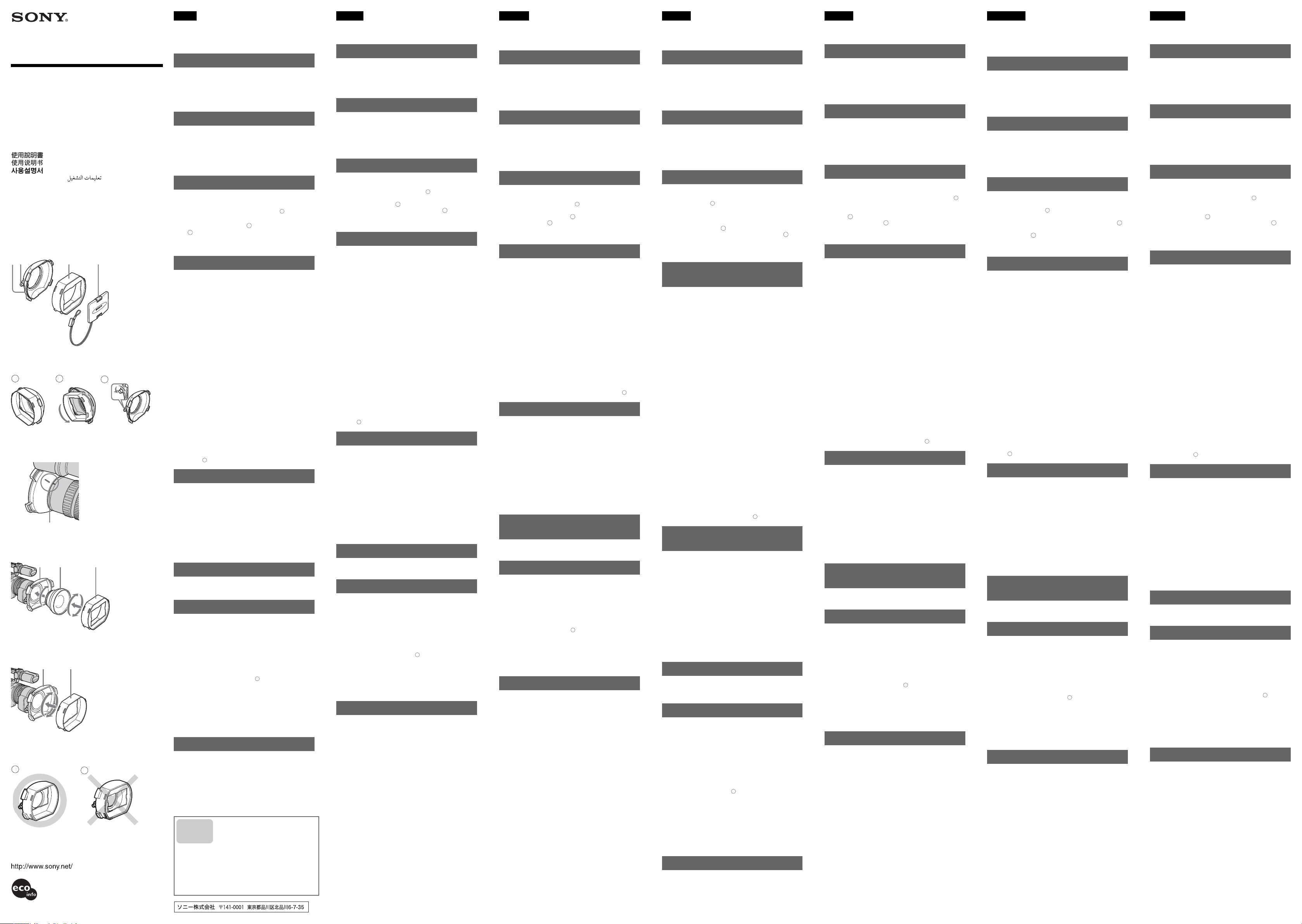
(イラストA)
ベースフード
a.
レンズフード固定ネジ
b.
フロントフード
c.
フードキャップ
d.
はじめに
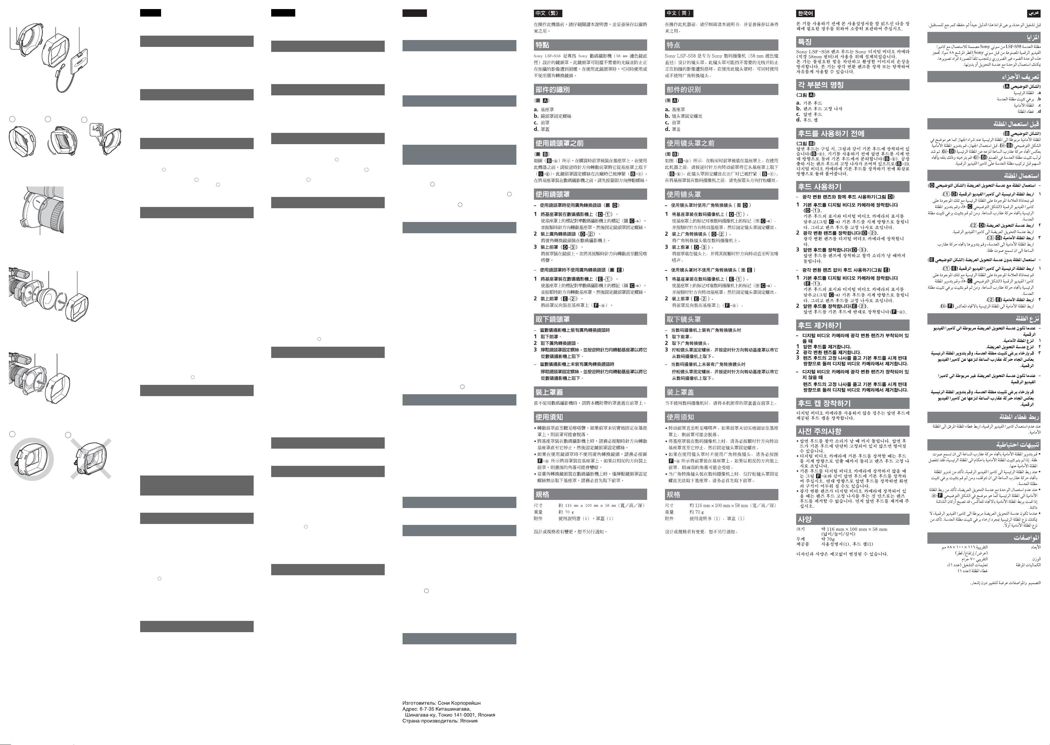
(イラストB)
ご購入時には、図のようにフロントフードがベースフード
に取り付けられた状態になっています(B
なる前に、図のようにフロントフードを反時計方向に回し
て取りはずしてください(B
c
(B
)もしっかりと固定された状態になっていますの
–
で、矢印の方向に回してゆるめてから、デジタルビデオカ
メラに装着してください。
)。レンズフード固定ネジ
b
–
a
)。お使いに
–
フードの使いかた
ワイドコンバージョンレンズを装着する場合
–
(イラストD)
デジタルビデオカメラにベースフードを取り付ける
1
(D–1)。
ベースフードのマークとデジタルビデオカメラのマーク
を合わせ(イラストC–a)、時計方向に回して取り付け
てください。その後、レンズフード固定ネジを締めてく
ださい。
ワイドコンバージョンレンズを取り付ける(D–2)。
2
ワイドコンバージョンレンズを装着してください。
フロントフードを取り付ける(D–3)。
3
フロントフードを取り付け、時計方向にカチッとロック
するまで回してください。
ワイドコンバージョンレンズを装着しない場合
–
(イラストE)
デジタルビデオカメラにベースフードを取り付ける
1
(E–1)。
ベースフードのマークとデジタルビデオカメラのマーク
を合わせ(イラストC
てください。その後、レンズフード固定ネジを締めてく
ださい。
フロントフードを取り付ける(E–2)。
2
ワイドコンバージョンレンズを装着する場合と反対の向
a
き(F
)で取り付けてください。
–
)、時計方向に回して取り付け
–a
フードのはずしかた
ワイドコンバージョンレンズが装着されている場合
–
フロントフードをはずす。
1
ワイドコンバージョンレンズをはずす。
2
レンズフード固定ネジをゆるめ、ベースフードを反時計
3
方向に回してはずす。
ワイドコンバージョンレンズが装着されていない場合
–
レンズフード固定ネジをゆるめ、ベースフードを反時計
方向に回してはずす。
フードキャップを付ける
デジタルビデオカメラを使用しないときは、付属のフード
キャップをフロントフードの窓に取り付けてください。
使用上のご注意
フロントフードはカチッとロックするまで回してくださ
•
い。しっかり固定されていないとはずれる恐れがありま
す。
デジタルビデオカメラにベースフードを装着するとき
•
は、必ずベースフードが止まるまで回してから、レンズ
フード固定ネジを締めてください。
ワイドコンバージョンレンズを装着しないときは、フロ
•
ントフードは必ずイラストF
さい。反対に装着されますと、画面の四隅が暗くなる
(ケラレ)ことがあります。
ワイドコンバージョンレンズが装着されている場合は、
•
レンズフード固定ネジをゆるめてもベースフードをはず
すことはできません。必ずフロントフードからはずして
ください。
a
の向きで装着してくだ
–
主な仕様
最大外形寸法 約
質量 約
付属品 取扱説明書(1)、フードキャップ(1)
本機の仕様および外観は、改良のため予告なく変更するこ
とがありますが、ご了承ください。
お問い合わせ
窓口のご案内
電話のおかけ
間違いにご注
意ください。
116 × 100 × 58 mm
(幅
× 高さ ×
奥行き)
70 g
■テクニカルインフォメーションセンター
ご使用上での不明な点や技術的なご質問
のご相談窓口です。
電 話:
受付時間: 月 〜 金曜日
(ただし、年末、年始、祝日を除く)
お電話される際に、本機の型名(
S58
より迅速な対応が可能になります。
0564-62-4979
時〜午後5時
午前
9
)をお知らせください。
LSF-
English
Before operating the unit, please read this manual
thoroughly and retain it for future reference.
Features
The Sony LSF-S58 is a lens hood designed for use with a
Sony digital video camera (58 mm filter diameter). The
unit will block off unnecessary light and prevent damage
to the image you are shooting. You can use the unit with
or without a wide conversion lens.
Identifying the parts
(Fig.A)
a. Base hood
b. Lens hood fastening screw
c. Front hood
d. Hood cap
Before using the hood
(Fig.B)
The front hood is attached to the base hood at the time of
purchase as shown in the figure (B–
unit, turn the front hood counterclockwise to remove it
from the base hood (B–
screw has been tightened at the factory (B–c); loosen it
by turning it in the direction of the arrow before attaching
the base hood to a digital video camera.
). The lens hood fastening
b
a
). Before using the
Using the hood
– Using the hood with a wide conversion lens (Fig.D)
1 Attach the base hood to the digital video camera
(D–1).
Match the mark on the base hood and that on the
digital video camera (Fig.C–a), and turn the base
hood clockwise. Then fasten the lens hood fastening
screw.
2 Attach a wide conversion lens (D–2).
Attach the wide conversion lens to the digital video
camera.
3 Attach the front hood (D–3).
Attach the front hood to the lens, and turn it clockwise
until it clicks.
– Using the hood without a wide conversion lens
(Fig.E)
1 Attach the base hood to the digital video camera
(E–1).
Match the mark on the base hood and that on the
digital video camera (Fig.C–a), and turn the base
hood clockwise. Then fasten the lens hood fastening
screw.
2 Attach the front hood (E–2).
Attach the front hood to the base hood backwards
a
(F–
).
Removing the hood
– When there is a wide conversion lens attached to
the digital video camera
1 Remove the front hood.
2 Remove the wide conversion lens.
3 Loosen the lens hood fastening screw, and turn the
base hood counterclockwise to remove it from the
digital video camera.
– When a wide conversion lens is not attached to the
digital video camera
Loosen the lens hood fastening screw, and turn the
base hood counterclockwise to remove it from the
digital video camera.
Attaching the hood cap
When you are not using the digital video camera, attach
the supplied hood cap to the front hood.
Precautions
• Turn the front hood until it clicks. If the front hood is
not fastened securely to the base hood, the front hood
may come off.
• When attaching the base hood to the digital video
camera, make sure that you turn the hood clockwise
until it stops, and then fasten the lens hood fastening
screw.
• If you are not using the unit with a wide conversion
lens, make sure that you attach the front hood to the
base hood as shown in Fig.F–
hood in the opposite direction, the corners of the screen
may darken.
• When the wide conversion lens is attached to the digital
video camera, you cannot remove the base hood by just
loosening the lens hood fastening screw. Make sure that
you remove the front hood first.
a
. If you attach the frond
Specifications
Dimensions Approx. 116 × 100 × 58 mm
Mass Approx. 70 g (2.5 oz)
Supplied accessories Operating instructions (1),
Design and specifications are subject to change without
notice.
(w/h/d)
(4 5/8 × 4 × 2 3/8 inches)
Hood cap (1)
Français
Avant d’utiliser cet accessoire, lisez ce manuel avec
attention et conservez-le pour pouvoir le consulter
ultérieurement.
Caractéristiques
Le modèle Sony LSF-S58 est un pare-soleil prévu pour être
utilisé sur un caméscope numérique Sony (diamètre du
filtre de 58 mm). Cet accessoire permet de filtrer la
lumière trop vive et empêche l’altération des images que
vous filmez. Vous pouvez utiliser l’accessoire avec ou sans
objectif à conversion grand angle.
Identification des pièces
(Fig.A)
a. Base
b. Vis de fixation
c. Pare-soleil
d. Capuchon d’objectif
Avant d’utiliser le pare-soleil
(Fig.B)
Le pare-soleil est fixé à la base au moment de l’achat,
comme indiqué à la figure (B–a). Avant d’utiliser
l’appareil, tournez le pare-soleil dans le sens anti-horaire
pour le retirer de la base (B–
serrée en usine (B–c); desserrez-la en la tournant dans
le sens de la flèche avant de fixer la base à un caméscope
numérique.
). La vis de fixation est
b
Utilisation du pare-soleil
– Utilisation du pare-soleil avec un grand angle
(Fig.D)
1 Fixez la base sur le caméscope numérique (D–1).
Alignez la marque de la base sur celle du caméscope
numérique (Fig.C–a) et tournez la base dans le sens
horaire. Serrez ensuite la vis de fixation.
2 Fixez un grand angle (D–2).
Fixez le grand angle sur le caméscope numérique.
3 Fixez le pare-soleil (D–3).
Fixez le pare-soleil sur l’objectif et tournez-le dans le
sens horaire jusqu’à ce qu’il s’encliquette.
– Utilisation du pare-soleil sans grand angle (Fig.E)
1 Fixez la base sur le caméscope numérique (E–1).
Alignez la marque de la base sur celle du caméscope
numérique (Fig.C–a) et tournez la base dans le sens
horaire. Serrez ensuite la vis de fixation.
2 Fixez le pare-soleil (E–2).
Fixez le pare-soleil sur la base par l’arrière (F–
a
).
Retrait du pare-soleil
– Si un grand angle est fixé sur le caméscope
numérique
1 Retirez le pare-soleil.
2 Retirez le grand angle.
3 Desserrez la vis de fixation du pare-soleil et
tournez la base dans le sens anti-horaire pour la
détacher du caméscope numérique.
– Si un grand angle n’est pas fixé sur le caméscope
numérique
Desserrez la vis de fixation et tournez la base dans
le sens anti-horaire pour la détacher du caméscope
numérique.
Mise en place du capuchon
d’objectif
Si vous n’utilisez pas le caméscope numérique, placez le
capuchon d’objectif sur le pare-soleil.
Précautions
•Tournez le pare-soleil jusqu’à ce qu’il s’encliquette. Si le
pare-soleil n’est pas correctement fixé à la base, il risque
de tomber.
• Lorsque vous fixez la base sur le caméscope numérique,
tournez-la dans le sens horaire jusqu’à son point d’arrêt,
puis serrez la vis de fixation.
• Si vous n’utilisez pas l’accessoire avec un grand angle,
veillez à fixer correctement le pare-soleil sur la base,
comme indiqué à la Fig.F–
soleil en sens inverse, les coins de l’écran risquent d’être
assombris.
• Lorsque le grand angle est fixé sur le caméscope
numérique, vous ne pouvez pas retirer la base
simplement en desserrant la vis de fixation. Détachez au
préalable le pare-soleil.
a
. Si vous fixez le pare-
Spécifications
Dimensions Environ 116 × 100 × 58 mm
Poids Environ 70 g (2,5 onces)
Accessoires fournis Mode d’emploi (1),
La conception et les spécifications sont sujettes à
modification sans préavis.
(l/h/p)
(4 5/8 × 4 × 2 3/8 pouces)
Capuchon d’objectif (1)
Deutsch
Lesen Sie diese Anleitung vor Inbetriebnahme des Geräts
bitte genau durch und bewahren Sie sie zum späteren
Nachschlagen sorgfältig auf.
Merkmale
Die Gegenlichtblende LSF-S58 von Sony ist für digitale
Videokameras von Sony mit einem Filterdurchmesser von
58 mm geeignet. Sie schützt vor übermäßigem Lichteinfall
und verhindert somit Qualitätseinbußen bei den
Aufnahmen. Sie können die Gegenlichtblende mit oder
ohne Weitwinkelkonverter verwenden.
Teileliste
(Abb. A)
a. Basisteil der Gegenlichtblende
b. Befestigungsschraube der Gegenlichtblende
c. Vorderteil der Gegenlichtblende
d. Schutzkappe
Vorbereitungen
(Abb. B)
Beim Kauf ist das Vorderteil der Gegenlichtblende wie in
der Abbildung (B–
Gegenlichtblende angebracht. Bevor Sie die
Gegenlichtblende verwenden können, müssen Sie das
Vorderteil gegen den Uhrzeigersinn drehen und vom
Basisteil abnehmen (B–
Gegenlichtblende wurde im Werk angezogen (B–c).
Lösen Sie sie, indem Sie sie in Pfeilrichtung drehen, bevor
Sie das Basisteil der Gegenlichtblende an der digitalen
Videokamera anbringen.
a
) gezeigt am Basisteil der
). Die Befestigungsschraube der
b
Verwenden der
Gegenlichtblende
–Verwenden der Gegenlichtblende mit einem
Weitwinkelkonverter (Abb. D)
1 Bringen Sie das Basisteil der Gegenlichtblende an
der digitalen Videokamera an (D–1).
Richten Sie die Markierung am Basisteil der
Gegenlichtblende an der Markierung der digitalen
Videokamera aus (Abb. C–a) und drehen Sie das
Basisteil der Gegenlichtblende im Uhrzeigersinn.
Ziehen Sie dann die Befestigungsschraube der
Gegenlichtblende an.
2 Bringen Sie einen Weitwinkelkonverter an (D–2).
Bringen Sie den Weitwinkelkonverter an der digitalen
Videokamera an.
3 Bringen Sie das Vorderteil der Gegenlichtblende an
(D–3).
Bringen Sie das Vorderteil der Gegenlichtblende am
Objektiv an und drehen Sie es im Uhrzeigersinn, bis es
mit einem Klicken einrastet.
– Verwenden der Gegenlichtblende ohne
Weitwinkelkonverter (Abb. E)
1 Bringen Sie das Basisteil der Gegenlichtblende an
der digitalen Videokamera an (E–1).
Richten Sie die Markierung am Basisteil der
Gegenlichtblende an der Markierung der digitalen
Videokamera aus (Abb. C–a) und drehen Sie das
Basisteil der Gegenlichtblende im Uhrzeigersinn.
Ziehen Sie dann die Befestigungsschraube der
Gegenlichtblende an.
2 Bringen Sie das Vorderteil der Gegenlichtblende an
(E–2).
Bringen Sie das Vorderteil der Gegenlichtblende
andersherum am Basisteil an (F–
a
).
Abnehmen der
Gegenlichtblende
– Wenn ein Weitwinkelkonverter an der digitalen
Videokamera angebracht ist
1
Nehmen Sie das Vorderteil der Gegenlichtblende ab.
2 Nehmen Sie den Weitwinkelkonverter ab.
3 Lösen Sie die Befestigungsschraube der
Gegenlichtblende und drehen Sie das Basisteil der
Gegenlichtblende gegen den Uhrzeigersinn, um es
von der digitalen Videokamera abzunehmen.
– Wenn kein Weitwinkelkonverter an der digitalen
Videokamera angebracht ist
Lösen Sie die Befestigungsschraube der
Gegenlichtblende und drehen Sie das Basisteil der
Gegenlichtblende gegen den Uhrzeigersinn, um es
von der digitalen Videokamera abzunehmen.
Anbringen der Schutzkappe
Wenn Sie die digitale Videokamera nicht benutzen,
bringen Sie die mitgelieferte Schutzkappe am Vorderteil
der Gegenlichtblende an.
Sicherheitsmaßnahmen
• Drehen Sie das Vorderteil der Gegenlichtblende, bis es
mit einem Klicken einrastet. Wenn das Vorderteil der
Gegenlichtblende nicht fest am Basisteil befestigt ist,
kann sich das Vorderteil der Gegenlichtblende lösen.
• Wenn Sie das Basisteil der Gegenlichtblende an der
digitalen Videokamera anbringen, achten Sie darauf, die
Gegenlichtblende bis zum Anschlag im Uhrzeigersinn
zu drehen und anschließend die Befestigungsschraube
der Gegenlichtblende anzuziehen.
• Wenn Sie keinen Weitwinkelkonverter verwenden,
bringen Sie das Vorderteil der Gegenlichtblende
unbedingt wie in Abb. F–
Wenn Sie das Vorderteil der Gegenlichtblende falsch
herum anbringen, sind die Ecken des angezeigten Bildes
unter Umständen dunkel.
• Wenn ein Weitwinkelkonverter an der digitalen
Videokamera angebracht ist, können Sie das Basisteil
der Gegenlichtblende nicht einfach abnehmen, indem
Sie die Befestigungsschraube der Gegenlichtblende
lösen. Sie müssen zuerst das Vorderteil der
Gegenlichtblende abnehmen.
a
dargestellt am Basisteil an.
Technische Daten
Abmessungen ca. 116 × 100 × 58 mm (B/H/T)
Gewicht ca. 70 g
Mitgeliefertes Zubehör Bedienungsanleitung (1),
Änderungen, die dem technischen Fortschritt dienen,
bleiben vorbehalten.
Schutzkappe (1)
Español
Antes de utilizar la unidad, lea este manual atentamente y
consérvelo para consultarlo en el futuro.
Características
Sony LSF-S58 es un parasol de objetivo diseñado para
cámaras de vídeo digitales Sony (diámetro de filtro de 58
mm). Este elemento bloqueará la luz innecesaria y evitará
anomalías en la imagen que está tomando. Puede utilizar
este elemento con o sin la lente de conversión gran
angular.
Identificación de las piezas
(Fig. A)
a. Base del parasol
b. Tornillo de fijación del parasol
c. Frontal del parasol
d. Tapa del parasol
Antes de utilizar el parasol
(Fig. B)
El producto se suministra con el frontal del parasol
colocado en la base como se muestra en la figura (B–a).
Antes de utilizar la unidad, gire el frontal del parasol en el
sentido contrario a las agujas del reloj para extraerlo de la
base (B–
apretado de fábrica (B–c). Para aflojarlo, hágalo girar en
la dirección de la flecha antes de fijar la base del parasol a
una videocámara digital.
). El tornillo de fijación del parasol viene
b
Uso del parasol
– Uso del parasol con una lente de conversión gran
angular (Fig. D)
1 Coloque la base del parasol en la cámara de vídeo
digital (D–1).
La marca de la base del parasol y la de la cámara de
vídeo digital deben coincidir (Fig. C–a). Gire el
parasol en el sentido de las agujas del reloj. A
continuación, apriete el tornillo de fijación del parasol.
2 Monte la lente de conversión gran angular (D–2).
Coloque la lente de conversión gran angular en la
videocámara digital.
3 Monte el frontal del parasol (D–3).
Coloque el parasol frontal en el objetivo y gírelo en el
sentido de las agujas del reloj hasta que encaje.
– Uso del parasol sin una lente de conversión gran
angular (Fig. E)
1 Coloque la base del parasol en la cámara de vídeo
digital (E–1).
La marca de la base del parasol y la de la cámara de
vídeo digital deben coincidir (Fig. C–a). Gire el
parasol en el sentido de las agujas del reloj. A
continuación, apriete el tornillo de fijación del parasol.
2 Monte el frontal del parasol (E–2).
Monte el frontal del parasol a la base colocándolo con
la parte de la ventana hacia atrás (F–
a
).
Extracción del parasol
– Con una lente de conversión gran angular montado
en la cámara de vídeo digital
1 Extraiga el frontal del parasol.
2 Extraiga la lente de conversión gran angular.
3 Afloje el tornillo de fijación del parasol y gire la
base en el sentido contrario de las agujas del reloj
para extraerla de la cámara de vídeo digital.
– Sin una lente de conversión gran angular montado
en la cámara de vídeo digital
Afloje el tornillo de fijación del parasol y gire la
base en el sentido contrario de las agujas del reloj
para extraerla de la cámara de vídeo digital.
Colocación de la tapa del
parasol
Cuando no utilice la cámara de vídeo digital, monte la
tapa proporcionada en el frontal del parasol.
Precauciones
• Gire el frontal del parasol hasta que oiga un clic. Si el
frontal del parasol no está correctamente fijado a la base,
es posible que se caiga.
• Al montar la base en la cámara de vídeo digital,
asegúrese de girarla en el sentido de las agujas del reloj
hasta que se detenga y, a continuación, apriete el tornillo
de fijación del parasol.
• Si no utiliza la unidad con una lente de conversión gran
angular, asegúrese de montar el frontal sobre la base tal
como se muestra en la Fig. F–
la dirección opuesta, es posible que las esquinas de la
pantalla aparezcan oscurecidas.
• Cuando se monta la lente de conversión gran angular en
la cámara de vídeo digital, no se puede extraer la base
con sólo aflojar el tornillo de fijación. Asegúrese de
extraer primero el frontal.
a
. Si monta el frontal en
Especificaciones
Dimensiones Aprox. 116 × 100 × 58 mm
Peso Aprox. 70 g
Accesorios incluidos Manual de instrucciones (1),
El diseño y las especificaciones están sujetos a cambios sin
previo aviso.
(an/al/prf)
Tapa del parasol (1)
Nederlands
Voordat u het apparaat gaat gebruiken, moet u deze
gebruiksaanwijzing aandachtig doorlezen. Bewaar de
gebruiksaanwijzing voor het geval u deze later als
referentiemateriaal nodig hebt.
Kenmerken
De Sony LSF-S58 is een lenskap die is ontworpen voor
gebruik met een digitale videocamera van Sony (met een
filterdiameter van 58 mm). De kap houdt ongewenst licht
tegen en voorkomt schade aan het beeld dat u opneemt. U
kunt de kap met of zonder groothoekvoorzetlens
gebruiken.
De onderdelen
(Afbeelding A)
a. Basiskap
b. Bevestigingsschroef voor de lenskap
c. Voorkap
d. Afsluitklepje voor de kap
Voordat u de kap gebruikt
(Afbeelding B)
De voorkap is bij de aanschaf op de basiskap bevestigd
zoals in afbeelding (B–
u het apparaat gaat gebruiken, draait u de voorkap
linksom om deze te verwijderen van de basiskap (B–
De bevestigingsschroef voor de lenskap is in de fabriek
vastgedraaid (B–
richting van de pijl te draaien voordat u de basiskap op de
digitale videocamera bevestigt.
a
) wordt weergegeven. Voordat
c
). Draai de schroef los door deze in de
b
De kap gebruiken
– De kap met een groothoekvoorzetlens gebruiken
(Afbeelding D)
1 Bevestig de basiskap op de digitale videocamera
(D–1).
Lijn de markering op de basiskap en die op de digitale
videocamera (Afbeelding C–a) uit en draai de
basiskap rechtsom. Draai de bevestigingsschroef voor
de lenskap vast.
2 Bevestig een groothoekvoorzetlens (D–2).
Bevestig de groothoekvoorzetlens op de digitale
videocamera.
3 Bevestig de voorkap (D–3).
Bevestig de voorkap op de lens en draai de voorkap
rechtsom tot deze vastklikt.
– De kap zonder groothoekvoorzetlens gebruiken
(Afbeelding E)
1 Bevestig de basiskap op de digitale videocamera
(E–1).
Lijn de markering op de basiskap en die op de digitale
videocamera (Afbeelding C–a) uit en draai de
basiskap rechtsom. Draai de bevestigingsschroef voor
de lenskap vast.
2 Bevestig de voorkap (E–2).
Bevestig de voorkap achterstevoren op de basiskap
a
(F–
).
De kap verwijderen
– Als er een groothoekvoorzetlens op de digitale
videocamera is bevestigd
1 Verwijder de voorkap.
2 Verwijder de groothoekvoorzetlens.
3 Draai de bevestigingsschroef voor de lenskap los
en draai de basiskap linksom om deze van de
digitale videocamera te verwijderen.
– Als er geen groothoekvoorzetlens op de digitale
videocamera is bevestigd
Draai de bevestigingsschroef voor de lenskap los
en draai de basiskap linksom om deze van de
digitale videocamera te verwijderen.
Het afsluitklepje voor de kap
bevestigen
Als u de digitale videocamera niet gebruikt, bevestigt u
het bijgeleverde afsluitklepje op de voorkap.
Voorzorgsmaatregelen
• Draai de voorkap tot deze vastklikt. Als de voorkap niet
stevig op de basiskap is bevestigd, kan de voorkap
losraken.
• Wanneer u de basiskap op de digitale videocamera
bevestigt, moet u de kap rechtsom draaien tot deze niet
verder kan. Vervolgens zet u de lenskap vast met de
bevestigingsschroef.
• Als u de kap zonder groothoekvoorzetlens gebruikt,
bevestigt u de voorkap op de basiskap zoals wordt
weergegeven in afbeelding F–
voorkap andersom, dan kunnen de hoeken van het
scherm donker worden.
•Wanneer de groothoekvoorzetlens op de digitale
videocamera is bevestigd, kunt u niet alleen de
bevestigingsschroef voor de lenskap losdraaien om de
basiskap te verwijderen. U moet eerst de voorkap
verwijderen.
a
. Bevestigt u de
Technische gegevens
Afmetingen Ongeveer 116 × 100 × 58 mm
Gewicht Ongeveer 70 g
Bijgeleverde accessoires Gebruiksaanwijzing (1),
Wijzigingen in ontwerp en technische gegevens
voorbehouden zonder voorafgaande kennisgeving.
(b/h/d)
Afsluitklepje voor de kap (1)
Português
Antes de utilizar o aparelho, leia este manual até ao fim e
guarde-o para consultas futuras.
Funções
A LSF-S58 da Sony é uma protecção de objectiva para
utilização com uma câmara de vídeo digital da Sony
(diâmetro do filtro 58 mm). A protecção evita a entrada da
luz desnecessária para não danificar a imagem que está a
filmar. Pode utilizar a unidade com ou sem uma lente de
conversão grande angular.
Identificar as peças
(Fig.A)
a. Protecção de base
b. Parafuso de fixação da protecção da objectiva
c. Protecção frontal
d. Tampa da protecção
Antes de utilizar a protecção
(Fig.B)
A protecção frontal está fixa à protecção de base na altura
da compra, como se mostra na figura (B–a). Antes de
utilizar a unidade, rode a protecção frontal no sentido
contrário ao dos ponteiros do relógio para retirá-la da
).
protecção de base (B–
protecção da objectiva foi apertado na fábrica (B–c);
desaperte o parafuso, rodando-o na direcção da seta antes
de montar a protecção de base numa câmara de vídeo
digital.
). O parafuso de fixação da
b
Utilizar a protecção
– Utilizar a protecção com uma lente de conversão
grande angular (Fig.D)
1 Monte a protecção de base na câmara de vídeo
digital (D–1).
Alinhe a marca da protecção de base com a existente
na câmara de vídeo digital (Fig.C–a) e rode a
protecção no sentido dos ponteiros do relógio. Depois
aperte o parafuso de fixação da protecção da objectiva.
2 Monte uma lente de conversão grande angular
(D–2).
Monte a lente de conversão grande angular na câmara
de vídeo digital.
3 Monte a protecção frontal (D–3).
Monte a protecção frontal na objectiva e rode-a no
sentido dos ponteiros do relógio até ouvir um estalido.
– Utilizar a protecção sem uma lente de conversão
grande angular (Fig.E)
1 Monte a protecção de base na câmara de vídeo
digital (E–1).
Alinhe a marca da protecção de base com a existente
na câmara de vídeo digital (Fig.C–a) e rode a
protecção no sentido dos ponteiros do relógio. Depois
aperte o parafuso de fixação da protecção da objectiva.
2 Monte a protecção frontal (E–2).
Monte a protecção frontal na protecção de base ao
contrário (F–
a
).
Retirar a protecção
– Se a câmara de vídeo tiver uma lente de conversão
grande angular montada
1 Retire a protecção frontal.
2 Retire a lente de conversão grande angular.
3 Desaperte o parafuso de fixação da protecção da
objectiva e retire a protecção de base da câmara de
vídeo digital rodando-a no sentido contrário ao dos
ponteiros do relógio.
– Se a câmara de vídeo não tiver uma lente de
conversão grande angular montada
Desaperte o parafuso de fixação e retire a
protecção de base da câmara de vídeo digital
rodando-a no sentido contrário ao dos ponteiros
do relógio.
Colocar a tampa da protecção
Se não estiver a utilizar a câmara de vídeo coloque a
tampa fornecida na protecção frontal.
Precauções
• Rode a protecção frontal até ouvir um estalido. Se não
ficar bem presa à protecção de base, a protecção frontal
pode desprender-se.
• Quando montar a protecção de base na câmara de vídeo
digital, rode-a no sentido dos ponteiros do relógio até
parar e depois aperte o parafuso de fixação respectivo.
• Se não estiver a utilizar a câmara com uma lente de
conversão grande angular, monte a protecção frontal na
protecção de base como se mostra na Fig.F–
montar a protecção virada ao contrário, os cantos do
ecrã podem ficar escuros.
• Quando a lente de conversão grande angular estiver
montada na câmara de vídeo digital, não pode retirar a
protecção de base desapertando apenas o parafuso de
fixação da protecção. Tem primeiro de retirar a
protecção frontal.
a
. Se
Características técnicas
Dimensões Aprox. 116 × 100 × 58 mm
Peso Aprox. 70 g
Acessórios fornecidos Manual de instruções (1),
Design e especificações sujeitos a alterações sem aviso
prévio.
(l/a/p)
Tampa da protecção (1)
A
a
B
a
C
D
E
F
a
b
cd
b
a
12 3
1
2
Italiano
Prima di utilizzare l’apparecchio, leggere attentamente il
manuale e conservarlo per eventuali riferimenti futuri.
Caratteristiche
Il modello Sony LSF-S58 è un paraluce progettato per
l’uso con una videocamera digitale Sony (diametro del
filtro 58 mm). Questo apparecchio consente di riparare la
videocamera digitale dall’esposizione eccessiva alla luce
onde evitare di danneggiare l’immagine ripresa. È
possibile utilizzarlo assieme a un obiettivo ad ampia
conversione.
Identificazione delle parti
(fig.A)
a. Base del paraluce
c
b. Vite di fissaggio del paraluce
c. Corpo del paraluce
d. Copriobiettivo
Prima di utilizzare il paraluce
(fig.B)
Al momento dell’acquisto, il corpo del paraluce è già
applicato alla base del paraluce, come mostrato nella
figura (B–a). Prima di utilizzare l’apparecchio, ruotare il
corpo del paraluce in senso antiorario per rimuoverlo
dalla base del paraluce (B–
paraluce è stata serrata in fabbrica (B–c). Prima di
applicare la base del paraluce ad una videocamera
digitale, allentare tale vite facendola ruotare in direzione
della freccia.
). La vite di fissaggio del
b
Uso del paraluce
– Uso del paraluce con l’obiettivo ad ampia
conversione (fig.D)
1 Applicare la base del paraluce alla videocamera
digitale (D–1).
Prestare attenzione a far corrispondere il simbolo sulla
base del paraluce a quello sulla videocamera digitale
(fig.C–a), ruotare la base del paraluce in senso orario,
quindi stringere utilizzando la vite di fissaggio del
paraluce.
2 Installare l’obiettivo ad ampia conversione (D–2).
Applicare l’obiettivo ad ampia conversione alla
videocamera digitale.
3 Applicare il corpo del paraluce (D–3).
Applicare il corpo del paraluce all’obiettivo, quindi
ruotare in senso orario fino ad udire uno scatto.
– Uso del paraluce senza l’obiettivo ad ampia
conversione (fig.E)
1 Applicare la base del paraluce alla videocamera
digitale (E–1).
Prestare attenzione a far corrispondere il simbolo sulla
base del paraluce a quello sulla videocamera digitale
(fig.C–a), ruotare la base del paraluce in senso orario,
quindi stringere utilizzando la vite di fissaggio del
paraluce.
2 Applicare il corpo del paraluce (E–2).
Applicare il corpo del paraluce alla base nella
direzione inversa (F–
a
).
Rimozione del paraluce
– Se nella videocamera digitale è installato un
obiettivo ad ampia conversione
1 Rimuovere il corpo del paraluce.
2 Rimuovere l’obiettivo ad ampia conversione.
3 Allentare la vite di fissaggio del paraluce, quindi
ruotare la base in senso antiorario per rimuoverla
b
dalla videocamera digitale.
–Se nella videocamera digitale non è installato un
obiettivo ad ampia conversione
Allentare la vite di fissaggio del paraluce, quindi
ruotare la base in senso antiorario per rimuoverla
dalla videocamera digitale.
Applicazione del
copriobiettivo
Se la videocamera digitale non viene utilizzata, applicare
il copriobiettivo in dotazione al corpo del paraluce.
Precauzioni
• Ruotare il corpo del paraluce fino a quando non scatta. Il
corpo del paraluce potrebbe staccarsi se non viene
fissato saldamente alla base.
• Durante l’applicazione della base del paraluce alla
videocamera digitale, accertarsi di ruotarla in senso
orario fino a quando non si arresta, quindi stringere la
vite di fissaggio del paraluce.
• Se non si utilizza l’apparecchio con un obiettivo ad
ampia conversione, accertarsi di applicare il corpo del
paraluce alla relativa base come illustrato nella
a
. Se il corpo del paraluce viene installato nella
fig.F–
direzione inversa, gli angoli dello schermo potrebbero
risultare oscurati.
• Se la videocamera digitale viene utilizzata con un
obiettivo ad ampia conversione, non è possibile
rimuovere la base del paraluce semplicemente
allentando la vite di fissaggio dello stesso. Accertarsi di
rimuovere prima il corpo del paraluce.
Caratteristiche tecniche
Dimensioni Circa 116 × 100 × 58 mm
Peso Circa 70 g
Accessori in dotazione Istruzioni per l’uso (1),
Il design e le caratteristiche tecniche sono soggetti a
modifiche senza preavviso.
(l/a/p)
Copriobiettivo (1)
Svenska
Innan du använder enheten bör du läsa igenom den här
bruksanvisningen noga. Förvara den sedan så att du i
framtiden kan använda den som referens.
Finesser
Sony LSF-S58 är ett motljusskydd som tillverkats för
användning med en digital videokamera från Sony (med
en filterdiameter på 58 mm). Skyddet tar bort onödigt ljus
och skyddar den filmade bilden. Du kan använda
motljusskyddet med eller utan en vidvinkellins.
De olika delarna
(Fig. A)
a. Huvudskydd
b. Skruv för fäste av motljusskyddet
c. Främre skydd
d. Täckbricka
Innan du använder skyddet
(Fig. B)
Det främre skyddet är fäst på huvudskyddet vid leverans
på det sätt som bilden visar (B–a). Innan du använder
enheten tar du bort det främre skyddet från
huvudskyddet genom att vrida det moturs (B–b).
Fästskruven på motljusskyddet är åtskruvad vid leverans
från fabriken (B–
pilens riktning innan du fäster huvudskyddet på en
digital videokamera.
c
); lossa den genom att skruva den i
Använda skyddet
– Använda skyddet med en vidvinkellins (Fig. D)
1 Fäst huvudskyddet på den digitala videokameran
(D–1).
Passa in märket på huvudskyddet till märket på den
digitala videokameran (Fig. C–a) och vrid sedan
huvudskyddet medurs. Skruva sedan åt
motljusskyddets fästskruv.
2 Sätt dit vidvinkellinsen (D–2).
Fäst vidvinkellinsen på den digitala videokameran.
3 Fäst det främre skyddet (D–3).
Fäst det främre skyddet på linsen, vrid det sedan
medurs tills det klickar på plats.
– Använda skyddet utan vidvinkellins (Fig. E)
1 Fäst huvudskyddet på den digitala videokameran
(E–1).
Passa in märket på huvudskyddet till märket på den
digitala videokameran (Fig. C–a) och vrid sedan
huvudskyddet medurs. Skruva sedan åt
motljusskyddets fästskruv.
2 Fäst det främre skyddet (E–2).
Vänd på det främre skyddet och fäst det på
huvudskyddet (F–
a
).
Ta bort skyddet
– När en vidvinkellins sitter på den digitala
videokameran
1 Ta bort det främre skyddet.
2 Ta bort vidvinkellinsen.
3 Skruva upp motljusskyddets fästskruv och ta sedan
bort huvudskyddet från den digitala videokameran
genom att vrida huvudskyddet moturs.
– När det inte sitter en vidvinkellins på den digitala
videokameran
Skruva upp motljusskyddets fästskruv och ta sedan
bort huvudskyddet från den digitala videokameran
genom att vrida huvudskyddet moturs.
Fästa täckbrickan
När du inte använder den digitala videokameran sätter du
fast den medföljande täckbrickan på det främre skyddet.
Försiktighetsåtgärder
• Vrid det främre skyddet tills det klickar på plats. Om
inte det främre skyddet sitter fast ordentligt på
huvudskyddet kan det främre skyddet lossna.
• När du fäster huvudskyddet på den digitala
videokameran ser du till att vrida skyddet medurs tills
det inte går att vrida mer, skruva sedan åt
motljusskyddets fästskruv.
• Använder du inte enheten med en vidvinkellins fäster
du det främre skyddet på huvudskyddet på det sätt som
visas i Fig. F–
åt andra hållet kan det hända att skärmens hörn blir
förmörkade.
• När en vidvinkellins är fäst på den digitala
videokameran kan du inte ta bort huvudskyddet genom
att bara lossa på motljusskyddets fästskruv. Ta först bort
det främre skyddet.
a
. Om du fäster det främre skyddet vänt
Tekniska data
Storlek Ca. 116 × 100 × 58 mm (b/h/d)
Vikt Ca. 70 g
Medföljande tillbehör Bruksanvisning (1),
Utförande och specifikationer kan ändras utan förbehåll.
Täckbricka (1)
Pyccкий
Пepeд экcплyaтaциeй ycтpойcтвa внимaтeльно
пpочтитe дaнноe pyководcтво и cоxpaнитe eго для
дaльнeйшиx cпpaвок.
Фyнкции
Sony LSF-S58 - это блeндa объeктивa,
пpeднaзнaчeннaя для иcпользовaния c цифpовыми
видeокaмepaми Sony (диaмeтp фильтpa 58 мм). Это
ycтpойcтво пpeпятcтвyeт попaдaнию излишнeго cвeтa
и пpeдотвpaщaeт yxyдшeниe кaчecтвa cнимaeмого
изобpaжeния. Уcтpойcтво можно иcпользовaть кaк c
шиpокоyгольным объeктивом, тaк и бeз нeго.
Oбознaчeниe чacтeй
(Pиc. A)
a.
Ocновaниe блeнды
b.
Bинт для кpeплeния блeнды объeктивa
c.
Пepeдняя чacть блeнды
d.
Кpышкa
Пepeд иcпользовaниeм
блeнды
(Pиc. B)
Bо вpeмя пpиобpeтeния пepeдняя чacть блeнды
пpикpeплeнa к ee оcновaнию, кaк покaзaно нa
pиcyнкe (B– ). Пepeд иcпользовaниeм ycтpойcтвa
повepнитe пepeднюю чacть блeнды пpотив чacовой
cтpeлки, чтобы cнять ee c оcновaния блeнды (B– ).
Bинт для кpeплeния блeнды объeктивa зaтянyт нa
зaводe-изготовитeлe ( ); отвepнитe eго в
нaпpaвлeнии cтpeлки, пpeждe чeм пpикpeпить
оcновaниe блeнды к цифpовой видeокaмepe.
a
b
c
B–
Иcпользовaниe блeнды
– Блeндa иcпользyeтcя c шиpокоyгольным
объeктивом (Pиc. D)
1
Пpиcоeдинитe оcновaниe блeнды к цифpовой
видeокaмepe ( 1).
Cовмecтитe мeтки нa оcновaнии блeнды и нa
цифpовой видeокaмepe и (Pиc. C–a) повepнитe
оcновaниe блeнды по чacовой cтpeлкe. Зaтeм
зaтянитe винт для кpeплeния блeнды объeктивa.
2
Пpиcоeдинитe шиpокоyгольный объeктив
(
D–
2).
Пpиcоeдинитe шиpокоyгольный объeктив к
цифpовой видeокaмepe.
3
Пpиcоeдинитe пepeднюю чacть блeнды ( 3).
Пpиcоeдинитe пepeднюю чacть блeнды к объeктивy
и повepнитe ee по чacовой cтpeлкe до щeлчкa.
– Блeндa иcпользyeтcя бeз шиpокоyгольного
объeктивa (Pиc. E)
1
Пpиcоeдинитe оcновaниe блeнды к цифpовой
видeокaмepe ( 1).
Cовмecтитe мeтки нa оcновaнии блeнды и нa
цифpовой видeокaмepe и (Pиc. C–a) повepнитe
оcновaниe блeнды по чacовой cтpeлкe. Зaтeм
зaтянитe винт для кpeплeния блeнды объeктивa.
2
Пpиcоeдинитe пepeднюю чacть блeнды ( 2).
Cновa пpиcоeдинитe пepeднюю чacть блeнды к
оcновaнию блeнды (F– ).
D–
D–
E–
E–
a
Cнятиe блeнды
– Ecли к кaмepe пpиcоeдинeн шиpокоyгольный
объeктив
1
Cнимитe пepeднюю чacть блeнды.
2
Cнимитe шиpокоyгольный объeктив.
3
Ocлaбьтe винт для кpeплeния блeнды
объeктивa, a зaтeм повepнитe оcновaниe
блeнды пpотив чacовой cтpeлки, чтобы cнять
eго c цифpовой видeокaмepы.
– Ecли к кaмepe нe пpиcоeдинeн
шиpокоyгольный объeктив
Ocлaбьтe винт для кpeплeния блeнды
объeктивa, a зaтeм повepнитe оcновaниe
блeнды пpотив чacовой cтpeлки, чтобы cнять
eго c цифpовой видeокaмepы.
Пpикpeплeниe кpышки
Ecли цифpовaя кaмepa нe иcпользyeтcя, пpикpeпитe
пpилaгaeмyю кpышкy к пepeднeй чacти блeнды.
Mepы пpeдоcтоpожноcти
• Повepнитe пepeднюю чacть блeнды до щeлчкa.
Ecли пepeдняя чacть блeнды нe пpикpeплeнa
нaдeжно к оcновaнию блeнды, то онa можeт cоcкочить.
• Пpи пpикpeплeнии оcновaния блeнды к цифpовой
видeокaмepe обязaтeльно повepнитe блeндy по
чacовой cтpeлкe до yпоpa, a зaтeм зaтянитe винт
для кpeплeния блeнды объeктивa.
• Ecли ycтpойcтво нe иcпользyeтcя c шиpокоyгольным
объeктивом, yбeдитecь, что пepeдняя чacть блeнды
пpикpeплeнa к оcновaнию блeнды, кaк покaзaно нa
Pиc. F– . Пpи пpиcоeдинeнии пepeднeй чacти
блeнды в обpaтном нaпpaвлeнии yглы экpaнa могyт
быть зaтeмнeны.
• Ecли шиpокоyгольный объeктив пpикpeплeн к
цифpовой видeокaмepe, то оcновaниe блeнды
нeльзя yдaлить пpоcто оcлaбив винт для кpeплeния
блeнды объeктивa. Cнaчaлa нeобxодимо cнять
пepeднюю чacть.
a
Texничecкиe xapaктepиcтики
Paзмepы Пpибл. 116 × 58 мм× 100
Macca Пpибл. 70 г
Пpилaгaeмыe пpинaдлeжноcти
Конcтpyкция и xapaктepиcтики могyт измeнятьcя бeз
пpeдвapитeльного yвeдомлeния.
(ш/в/г)
Инcтpyкция по экcплyaтaции
(1), кpышкa (1)
 Loading...