

Sony LN-1 Service Manual
KV-27TS35
RM-Y102
SERVICEMANUAL
US Model
Chassis No. SCC-E54H-A
Canadian Model
Chassis No. SCC-E65E-A
MODELS OF THE SAME SERIES
KV-27TS35
KV-27TS27/27TS31
KV-27TW75/27TW76
Television system American TV standards
Channel coverage VHF: 2 - 13
Picture tube
Antenna
Input
output
UHF: 14 - 69
Cable TV: 1 - 125
MicroblackTM Trinitron”
274nch
28-inch picture tube measured
diagonally
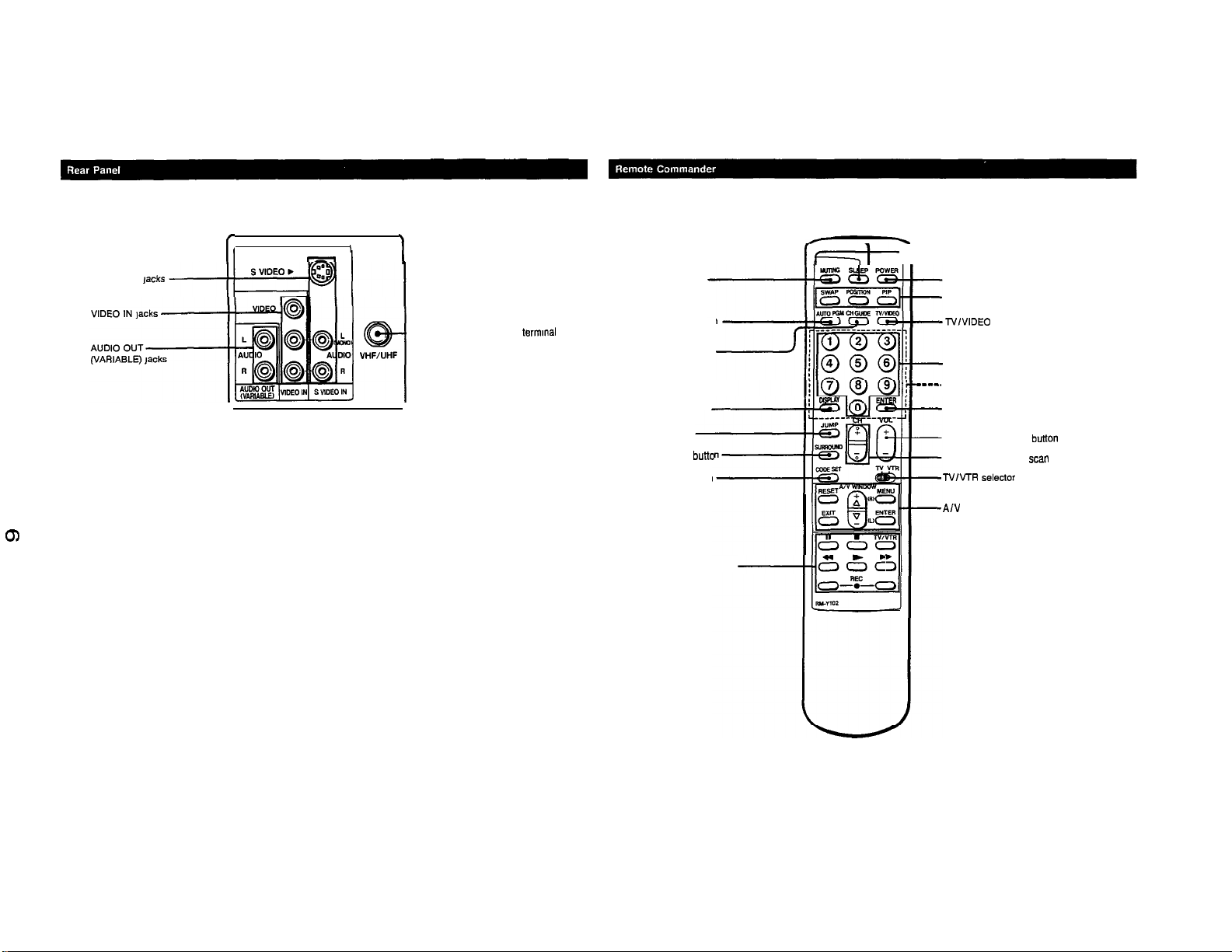
75ohm
VHF/UHF
VIDEO and S VIDEO
AUDIO OUT (VARIABLE) (phono jacks)
picture measured diagonally
external antenna terminal for
S VIDEO IN (S terminal)
Y: 1 Vp-p, 75-ohms
unbalanced, sync negative
C: 0.286 Vp-p (Burst signal),
75ohms
Video (phono jacks): 1 Vp-p,
75-ohms unbalanced,
sync negative
Audio (phono jacks): 500 mVrms
(100% modulation)
Impedance: 47 kilohms
More than 408
maximum volume setting (variable)
Impedance: 5 kilohms
mVrms
SPECIFICATIONS
tube
at the
Speaker output
Power requirements
Power consumption
Dimensions (w I h
Weight
Supplied accessories
Remote commander RM-Y 102 (1) with 2 size AA
(R6) EVEREADY batteries
Recommended accessories
U/V mixer EAC-66
Connecting cable
VMC-810/82OS,
Design and specifications are subject to change without
notice.
5Wx2
120 V AC, 60 Hz
17ow
5W Standby mode
660.5x602.5 x468
1
d)
(26% x
46 kg
(99lbs 402)
YC-15
23%
x 18% in.)
Vi30
V, RK-tiA
mm
996479501
TRINlTRONdOLOR
TV
SONX
KV-27TS35
RM-Y102
(CAUTION)
SHORT CIRCUIT THE ANODE OF THE PICTURE TUBE AND THE
ANODE CAPTOTHE METAL CHASSIS, CRTSHIELD, OR CARBON
PAINTED ON THE CRT, AFTER REMOVING THE ANODE.
WARNING!!
AN ISOLATION TRANSFORMER SHOULD BE USED DURING
ANY SERVICE TO AVOID POSSIBLE SHOCK HAZARD, BECAUSE
OF LIVE CHASSIS.
THE CHASSIS OF THIS RECEIVER IS DIRECTLY CONNECTED
TO THE AC POWER LINE.
SAFETY-RELATED COMPONENT WARNING !!
COMPONENTS IDENTIFIED BY SHADING AND MARK A ONTHE
SCHEMATIC DIAGRAMS, EXPLODED VIEWS AND IN THE PARTS
LIST ARE CRITICAL TO SAFE OPERATION. REPLACE THESE
COMPONENTS WITH SONY PARTS WHOSE PART NUMBERS
APPEAR AS SHOWN IN THIS MANUAL OR IN SUPPLEMENTS
PUBLISHED BY SONY. CIRCUIT ADJUSTMENTS THAT ARE
CRITICAL TO SAFE OPERATION ARE IDENTIFIED IN THIS
MANUAL. FOLLOW THESE PROCEDURES WHENEVER CRITICAL COMPONENTS ARE REPLACED OR IMPROPER OPERATION IS SUSPECTED.
(ATTENTION)
APRES AVOIR DECONNECTE LE CAP DE L’ANODE,
COURTCIRCUITER L’ANODE DU TUBE CATHODIQUE ET CELUI
DE L’ANODE DU CAPAU CHASSIS METALLIQUE DE L’APPAREIL,
OU AU COUCHE DE CARBONE PEINTE SUR LE TUBE
CATHODIQUE OU AU BLINDAGE DU TUBE CATHODIQUE.
ATTENTION!!
AFIN D’EVITER TOUT RISQUE D’ELECTROCUTION PROVENANT
D’UN
CHhSlS
D’ISOLEMENT DOIT ETRE UTILISli LORS DETOUT DEPANNAGE.
LE
CHhSlS
RACCORDtj:
ATTENTION AUX COMPOSANTS RELATliS ALA
LES COMPOSANTS IDENTIFIkS PAR UNE TRAME ET PAR UNE
MAPQUE A SUR LES SCHEMAS DE PRINCIPE, LES VUES
EXPLOSkES ET LES LISTES DE PIECES CONT D’UNE
IMPORTANCE CRITIQUE POUR LA
FONCTIONNEMENT. NE LE$ REMPLACER QUE PAR DES
COMPOSANTS SONY DONTLE NUMkRO DE
DANS LE PRliSENT MANUEL OU DANS DES SUPPLEMENTS
PUBLItS
L’IMPORTANCE EST CRITIQUE POUR LA
FONCTIONNEMENT SONT IDENTIFIES DANS LE PRESENT
MANUEL. SUIVRE CES PROCliDURES LORS DE CHAQUE
REMPLACEMENT DE COMPOSANTS CRITIQUES, OU
LORSQU’UN MAUVAIS FONCTIONNEMENT EST SUSPECTE.
SOUS TENSION, UN TRANSFORMATEUR
DE CE RliCEPTEUR EST DIRECTEMENT
A L’ALIMENTATION SECTEUR.
SliCURITk!!
SliCURITk
PI&E
EST INDlQUi
PAR SONY. LES REGLAGES DE CIRCUIT DONT
SliCURIT6
DU
DU
-2-
SAFETY CHECK-OUT
(US Model only)
Aftercorrectingtheoriginalserviceproblem,performthefollowing
safety checks before releasing the set to the customer
1.
Check the area of your repair for unsoldered or poorly-soldered
connections. Check the entire board surface for solder splashes
and bridges.
2.
Check the interboard
or contact high-wattage resistors.
3
Check that all control knobs, shields, covers, ground straps, and
mounting hardware have been replaced. Be absolutely certain that
you have replaced all the insulators
4 Look for unauthorized replacement parts, particularly transistors,
that were installed during a previous repair Point them out to the
customer and recommend their replacement.
5.
Look for part!, which, though functioning, show obvious
deterioration. Point them out to the customer and recommend
their replacement.
6.
Check the line cord for cracks and abrasion Recommend the
replacement of any such line cord to the customer
7. Check the condition of the monopole antenna (if any).
Make sure the end is not broken off, and has the plastic cap on it.
Point out the danger of impalement on a broken antenna to the
customer, and recommend the antenna’s replacement.
8.
Check the B+ and HV to see they are at the value5 specified. Make
sure your instruments are accurate; be suspicious of your HV
meter if sets always have low HV.
wning
to ensure that no wires are “pinched”
signs
LEAKAGE
The AC leakage from any exposed metal part to earth ground and
from all exposed metal parts to any exposed metal part having a return
to chassis, must not exceed 0.5 mA
current can be measured by any one of three methods.
1.
A commercial leakage tester, such as the Simpson 229 or RCA
WT-540A. Follow the manufacturers’ instructions to use these
instruments.
2.
A battery-operated AC milliammeter. The Data Precision 245
digital multimeter is suitable for this job.
3.
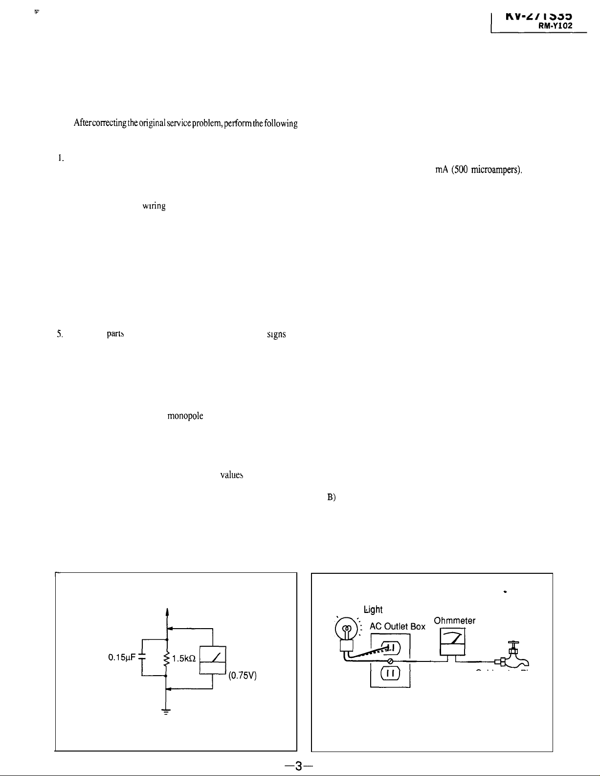
Measuring the voltage drop across a resistor by means of a VOM
or battery-operated AC voltmeter The “limit” indication is 0.75
V, so analog meters must have an accurate low-voltage scale The
Simpson 250 and Sanwa SH-63Trd are examples of a passive
of
VOM that is suitable. Nearly all battery operated digital multimeters
that have a 2V AC range are suitable. (See Fig. A)
HOW TO FIND A GOOD EARTH GROUND
A cold-water pipe is guaranteed earth ground; the cover-plate
retaining screw on most AC outlet boxes is also at earth ground. If the
retaining screw is to be used as your earth-ground, verify that it is at
ground by measuring the resistance between it and a coldwater pipe
with an ohmmeter. The reading should be zero ohms. If a cold-water
pipe is not accessible, connect a 60-100 watts trouble light (not a neon
lamp) between the hot side of the receptacle and the retaining screw.
Try both slots, if necessary, to locate the hot side of the line, the lamp
should light at normal brilliance if the screw is at ground potential. (See
Fig. 9)
(SO0 microampers).
Leakage
9.
Check the antenna terminals, metal trim, “metallized” knobs,
screws, and all other exposed metal parts for AC leakage Check
leakage as described below
To Exposed Metal
Parts on Set
0.15kF
f
Earth Ground
Fig A. Using an AC voltmeter to check AC leakage
AC
voltmeter
(0.75V)
-
Trouble Light
Cold-water Pipe
Fig. B. Checking for earth ground.
-3-
KV-27TS35 1
RM-Y102
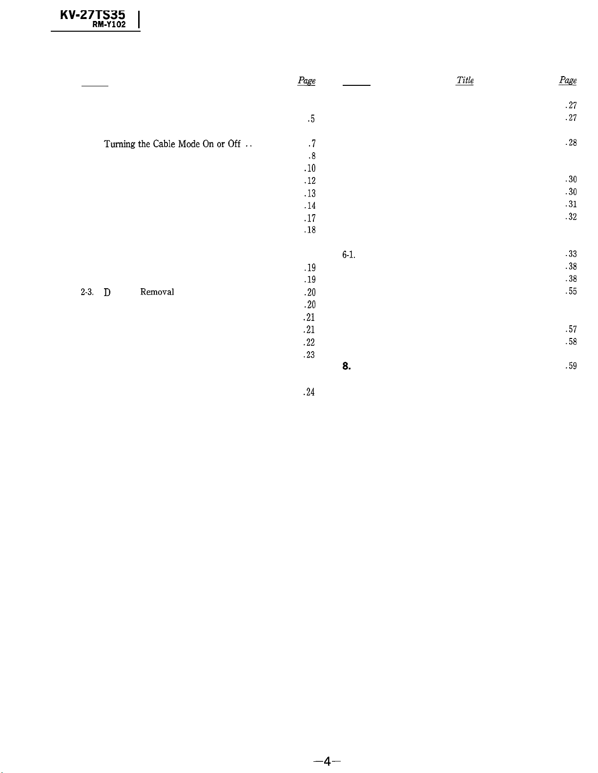
TABLE OF CONTENTS
Section
1. GENERAL
l-l. Locating the Controls ...........................
1-2.
Connecting TV Antenna/Cable ................
1-3.
TumingtheCableModeOnorOff.. .............
l-4. Presetting TV Channels ........................
l-5. Using Picture-in-Picture .......................
1-6.
Using the Pre-Programmed Remote Commander .
1-7.
Setting the CURRENT TIME ...................
1-8. Using the Timer-activated Functions-GUIDE ...
1-9.
Using CHANNEL CAPTION ...................
l-10. Enjoying Other Useful Features .................
2. DISASSEMBLY
2-1.
Rear Cover Removal .......................
2-2.
Service Position ...............................
2-3.D Board
2-4.
Antenna Terminal Board Removal ...............
2-5.
B, A and E Boards Removal.. .................
2-6.
How to Improve Interlace .......................
2-7.
B, A and E Boards Service Position .............
2-8.
Picture Tube Removal .....................
3. SET-UP ADJUSTMENTS
3-1.
Beam Landing ..............................
3-2.
Convergence .............................
Removal
Title
...............................
&
.lO
.12
.13
.14
.17
.18
.19
.19
.20
.20
.21
.21
.22
.23
.24
..2 5
.5
.7
.8
Section
3-3.
Focus Adjustment .....................
3-4.
White Balance ..............................
7
4. SAFETY RELATED ADJUSTMENTS
5. CIRCUIT ADJUSTMENTS
5-1.
A Board Adjustments ......................
5-2.
B Board Adjustments ...................
5-3.
D Board Adjustments ......................
5-4.
E Board Adjustments .....................
6. DIAGRAMS
6-l.
Block Diagram .............................
6-2.
Circuit Boards Location ...................
6-3.
Printed Wiring Boards and Schematic Diagrams .
6-4.
Semiconductors ..........................
7. EXPLODED VIEWS
7-l. Chassis. ..................................
7-2.
Picture Tube .............................
8.
ELECTRICAL PARTS LIST
m
............
..........
&
.27
.27
.28
.30
.30
.31
.32
.33
.38
.38
.55
.57
.58
.59
-4-
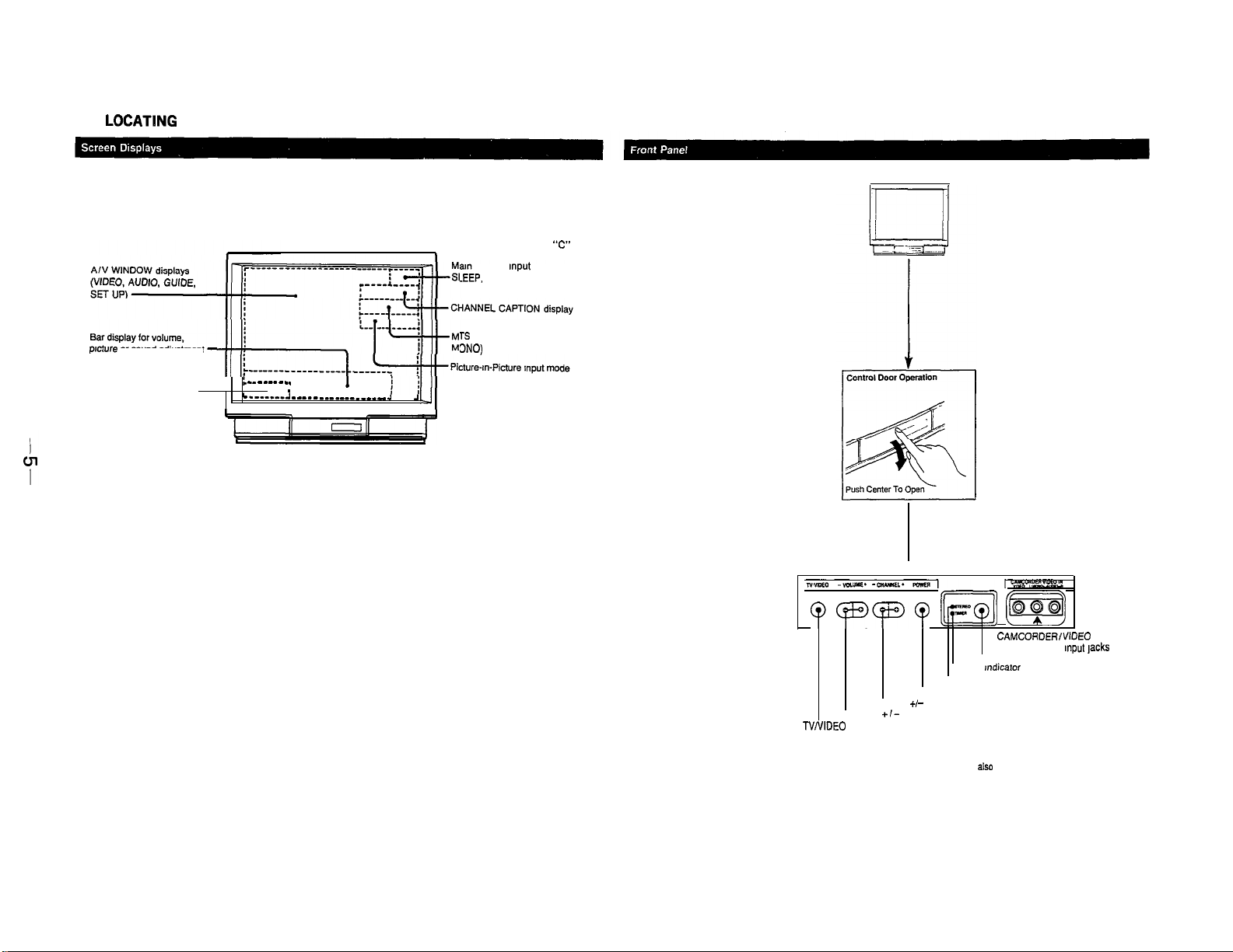
l-l.
LOCATlNG
picture
or sound adjustment
CURRENT TIME display
SURROUND display
THE CONTROLS
: -- - - -- -
_.
.
I
C-------A
1
-----____________ J
ii
____
Channel number/cable “C”
1
displays
Picture Input mode
.EEP, MUTING displays
TS
mode (MAIN, SAP or
3NO)
J
4
SECTION 1
GENERAL
oapo
CHANNEL +!- buttons*
VOLUME
TV/VIDEO button*
POWER button*
+I-
buttons*
m
STEREO Indicator lamp
[m)
CAMCORDERlVlDEO IN
VIDEO, AUDIO Input tacks
Remote detector
TIMER mdicator lamp
*Buttons with the same function are
also located on the Remote
Commander.
m
S VIDEO IN jacks
I,
II
I
I
I
-VHF/UHF antenna terminal
MUTING button
AUTO PGM
CH GUIDE button
DISPLAY button
JUMP button
SURROUND butto
CODE SET button
(Pre-Programmed
function)
button
[ r
(--+---
SLEEP button
POWER button
Picture-m-Picture buttons
TV/VIDEO button
O-9 buttons
----.
CHANNEL GUIDE directory keys
ENTER button
VOL (volume) +/CH (channel) +I-
TvlvrR
Selector
(Video equipment operation)
A/V WINDOW buttons
SW
button
I
I
Video operating buttons
~HZh52
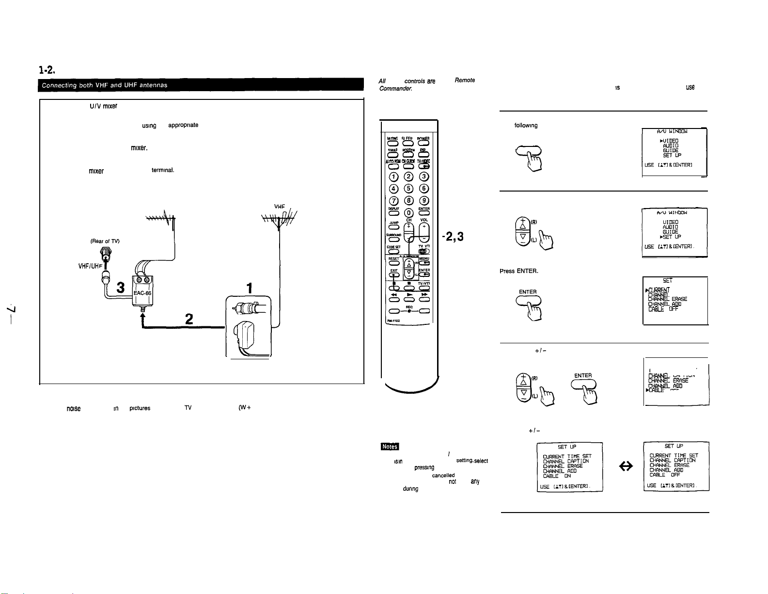
1-2. CONNECTING TV ANTENNA/CABLE
Use the EAG66 U/V mwer (not supplied).
Prepare the VHF antenna end usmg the appropriate connector (p. 12)
1
Connect the cables to the mixer.
2
Attach the mixer to the VHF/UHF termmal.
3
1-3. TURNING THE CABLE MODE ON OR OFF
All of the contmk are on the Remote
UJmc
YEEQ
000
000
NJmwoIGuE
P(IWER
5W.P
Rlsmw
Ap
TyhnEc
008
-TV/VIDEO
If you have cable connected to your N , follow the steps below to turn
the cable connection on or off. Cable mode 1s preset to ON when you
your N for the first time; turn cable OFF to preset or watch VHF or UHF
channels.
Press MENU to display the
followmg screen.
1
MENU
-
uss
VHFlUH
When the U/V mixer is used
Snow and
Norse
may appear m the
UHF
prctures
of the cable TV channels over 37
(‘A’+
Press the +I- button to select SET UP
2
-2,3
AIV WINDOW
+/-
-1
MENU
-ENTER
-MIT
Press
+/-
button and
ENTER to select CABLE.
3
1)
Press the
+I-
button and ENTER to select ON or OFF alternately.
. YOU cannot set CABLE ON 1 OFF while the
TV IS m VIDEO mode. Before
TV mode by
l The menu will be cancelled automatically
pressmg
after 10 seconds if you do
buttons during that Lime.
TV/VIDEO.
not
setting. select
push
snY
To return to TV mode.
Press EXIT.
SET UP
.,X,R,?WT TIME SET
CHRNNEL
CAPTION
%E ER&SE
WBLE OFF
SET UP
CURRENT TIME SET
MRNNn CAPTION
CABLE
OFF
1
1
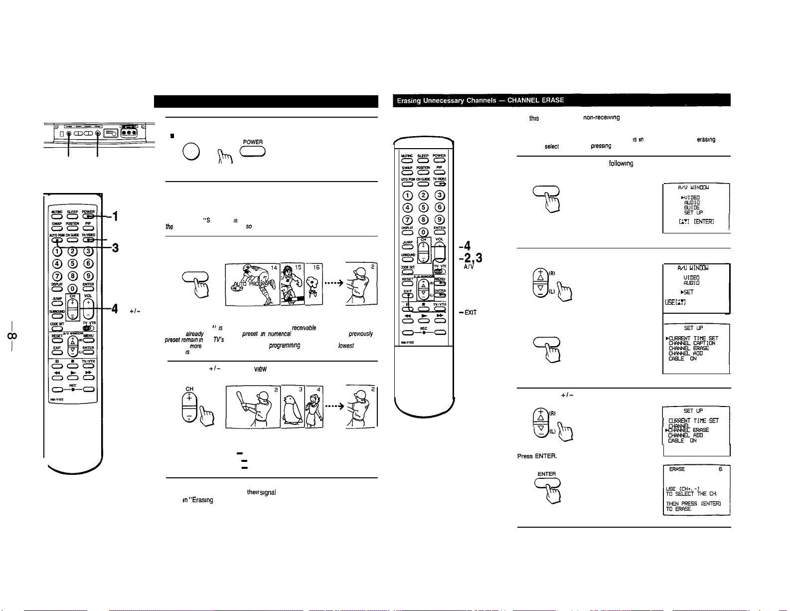
14. PRESETTING TV CHANNELS
Press POWER on the TV or the Remote Commander to turn the N on.
1
.
POWER
TV/VIDEO
POWER
POWER
-1
-N/VIDEO
AUTO PGM
-3
-4CH
cl-
Turn the cable connection on or off, depending on if you want to preset
cable or VHF/UHF channels.
2
If “VIDEO” or “9 VIDEO” IS displayed on the screen, press the N/VIDEO button on
the Nor the Remote Commander so that a channel number appears.
Press AUTO PGM.
3
AUTO PGM
“AUTO PROGRAM ” IS displayed on the screen and recavable channels (other than the
channels abea@ preset) will be preset m numer~al sequence. The channels prevrously
pmset re,ne,n n
When no more channels can be found. the pmgrammng stops and the lowest numbered
channel IS displayed.
Press CH
4
(FOLLOW THE STEPS ON P 14)
the N’s memory.
+/-
to check or wew preset channels.
-N/VIDEO
-4CH Cl-
-2,3
A,‘,
WINDOW
+/-
MENU
-1
-ENTER
-EXIT
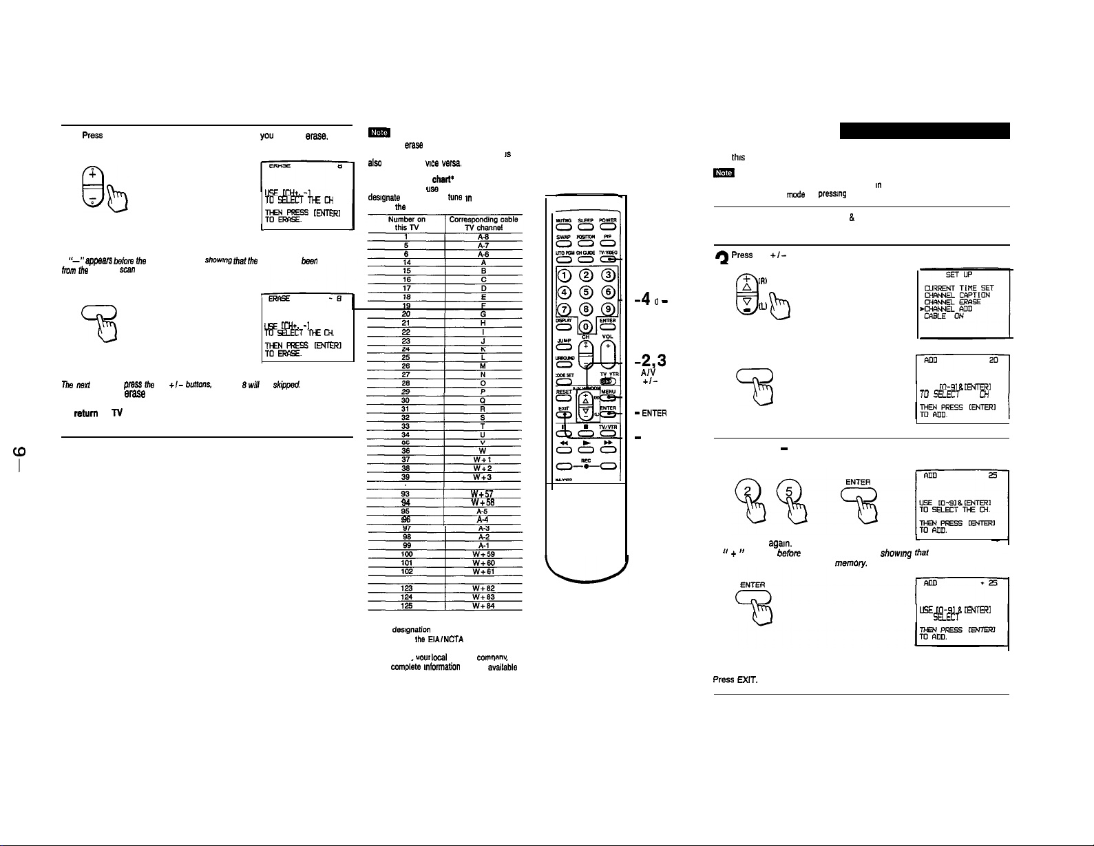
Use
this
feature to erase
memory.
Note
You cannot use CHANNEL ERASE while the
channels,
select
Press MENU to display the
N mode by
non-recetang
pressmg
N/VIDEO.
followmg
channels from the channel scan
N IS m VIDEO mode. Before erasmg
screen.
1
MENU
73
Press the +I- button to select SET UP
2
Press ENTER.
ENTER
Press the
+/-
button to select CHANNEL ERASE.
3
USE
till
8
[ENTERI
W” WINrnW
i!l%
GUIDE
GET
UP
“SE
II’1 8 IENTERI.
(TUWENT TIFlE 5ET
CHRNNEL
CAPTION
Channels that can be received on this TV:
To erase unnecessary channels, or to add channels that could not be
preset automatically because
steps m
Dewed Channels”
VHF 2 - 13
UHF 14 - 69
Cable: 1 - 125
their slgnal
“Erasmg
Unnecessary Channels” and “Presetting Only
strength was too weak, follow the
I
‘p
Press
the CH +I- button to select the channel
4
CH
Press ENTER.
A
“-”
appears tefore the channel number, showrng that
from the channel
The next time you press dm CH
Repeat step 4 to erase other channels.
To mum to TV mode
Press EXIT.
scan
memory.
73
+I-
buitons, channel .9 will be skipped.
you
want to erase.
LEE to+. -1
TDSELECTTHEM
gEr-!-r-!
I
(he
channel has been erased
Lls mi*. -1
TO SELECT
TIE
ENTEEI
When you
eras
cable N channel with the same number
also erased, and vice vwsa.
Cable N channel
Cable N systems use letters or numbers to
desIgnate channels. To
refer to
a VHF or UHF channel, the
chart*
tune ,n
the
chart below.
a channel,
IS
Use th!s feature to add channels one by one to the channel scan memory.
ImY
You cannot use CHANNEL ADD while the
channels. select N
mcds
by
(FOLLOW STEPS 1 & 2 ON)
press,ng
N
is m VIDEO mode. Before adding
N/VIDEO.
1-2
9 Press
the
+/-
-N/VIDEO
3
+
-4 0
-
9 buttonsENTER
M.
-2,3
A/V
WINDOW
+,-
-1
MENU
- ENT5R
-
EXIT
36
37
38
39
93
94 w+m
95 A-6
66 A-4
z
w
w+1
w+2
w+3
w+57
A
V
- (!J
8
Press ENTER.
ENTER
Press the 0 - 9 buttons to select the channel you want to add. For
example, to add channel 25, press 2, 5 and ENTER.
4
Press ENTER
A “ + ‘* appears before the channel number, showmg ihat the channel has
been added to the channel scan memow.
button to select CHANNEL ADD.
(R)
b
agam.
USE
to-91 8 IENTERI
TO
SELECT THE W
L
l This desfgnatfon of cable N channels
conforms to
recommendation.
Check with
more cornpI& mfwmation on the
channels.
the
EIAINCTA
vow
kxal cable N
comoaw
a&bls
for
Repeat step 4 to add other channels.
To return to TV mode
press
EXIT.
USE (O-91 8 CENTER1
TO
S!LECT
ME CH.
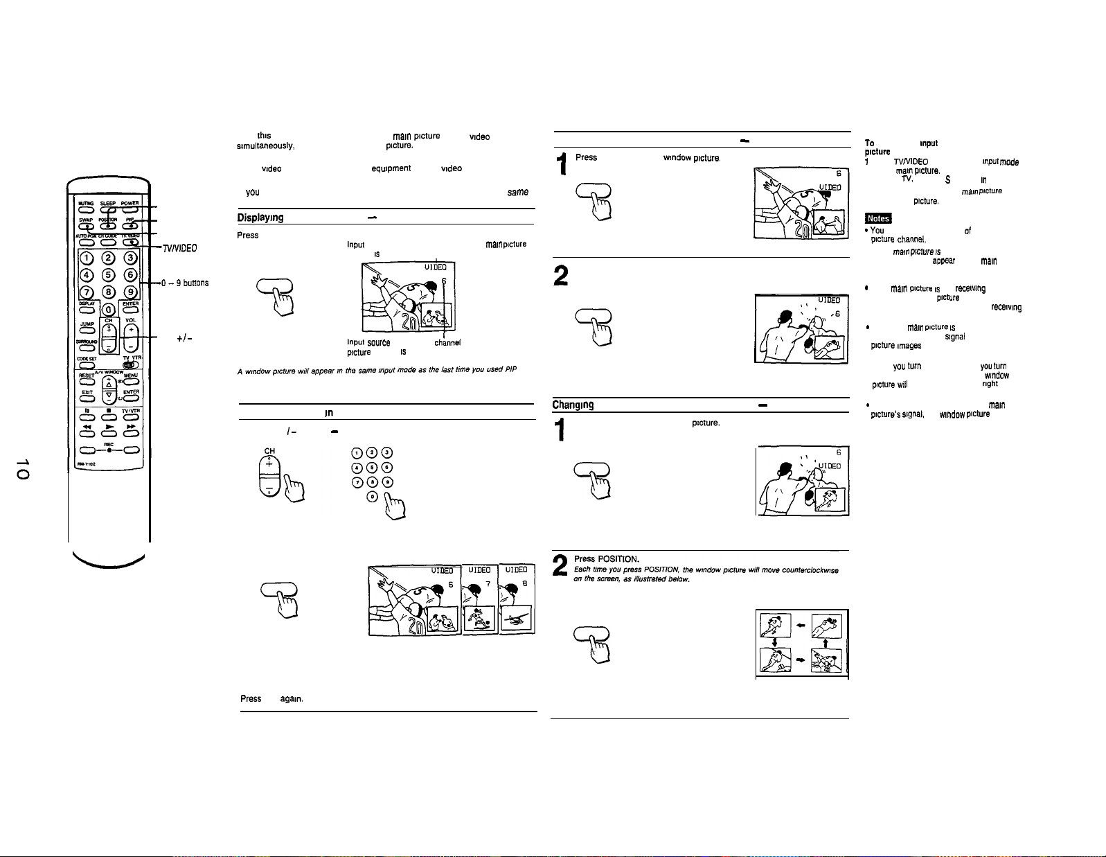
1-5. USING PICTURE-IN-PICTURE
With this feature, you can watch both the man
s8multaneously, by means of a wmdow picture.
For example. Use Picture-m-Picture when you want to watch a TV program
and a video source from connected equipment (VCR, wdeo disc player, etc.)
at the Same time.
If you connect a VCR, you can watch two different TV programs at the came
-POSITION
-PIP
-SWAP
-TVNIDEO
-CH
+I-
time.
Displaymg a window picture - PIP
press PIP
53
Scanning channels In the window picture
Press CH + I- or the 0 - 9 buttons and ENTER.
PIP
fxture
and a wdeo source.
input
source mode or N channel for the ma,”
(display IS green)
input so”rce
mode or N ch:nnel
pnture
(display IS white)
I
for the wmdow
pcture
Swapping the main and window pictures - SWAP
4
Press
PIP to display a wndow
I
PIP
33
Press SWAP
pncture.
2
SWAP
Changmg the position of the window picture
Press PIP to display a wmdow
pzcture.
1
PIP
-
POSITION
70 change the Input mode of the wmdow
pmture
1
Press NNIDEO to change the
of the
mam p,ctura.
(Selects N.
2 Press SWAP to swap the ma,”
the wmdow peture.
*You cannot hear the sound of the wmdow
plct”re ctianna,.
l If the
“BLOCKED” will
screen. and Picture-m-Picture will not
function.
*
If the man
Image. the wmdow
will reappear when you switch to a recewng
channel.
*
When the
depending on the N
picture mwges
white.
. When you
the TV on with PIP mode on. the
p!cture
screen.
*
Depending on the condition of the man
p~cture’s signal.
affected.
VIDEO. S VIDEO I” sequence)
mam prcture IS
wll appear at the bottom
blocked, the display
apoear
picture IS
not
picture
Mann picture IS
may also be black and
turn
PIP on. or when
the
wlndow picture
mpuf mcde
p,ct”re
on the man
recewm9
will disappear. It
black and white,
signal
some wmdow
you turn
nghf
an
window
of the
may be
with
ENTER
33
To make the window picture disappear
press PIP age,“.
POSITION
73
-2,3
-1
TV/VIDEO
SWAP
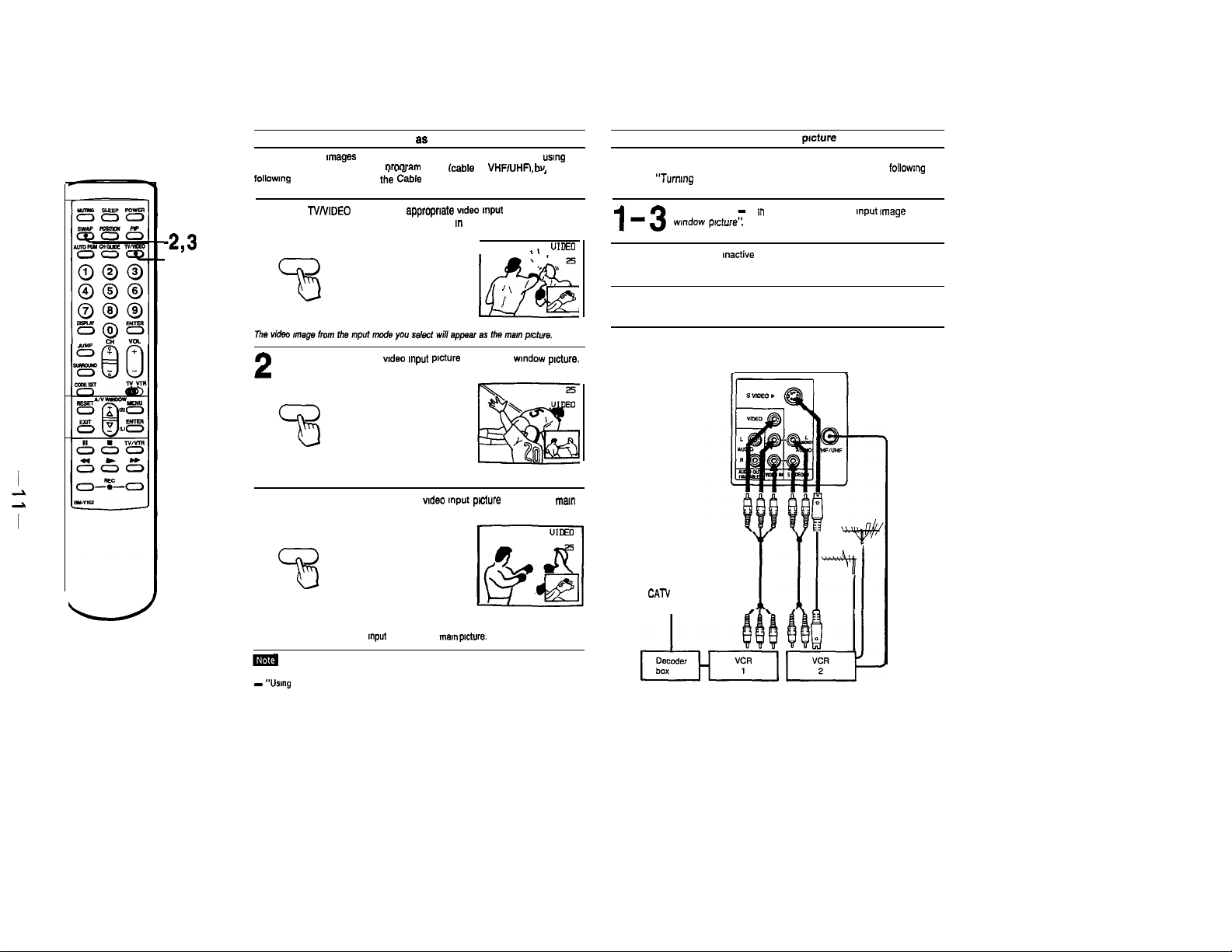
Displaying a VIDEO input image 8s a window picture
To watch VIDEO
Picture-In-Picture, first select a orooram mode icable or
followmg the steps, “Turnmg the
The” follow the steps below.
1
e
Press SWAP so that the vtdeo Input
rmages
(VCR playback or TV through a VCR tuner) ustng
C&e
Connection On or Off.”
Press NNIDEO to select the appropriate vrdeo mput mode.
(Selects TV, VIDEO and S VIDEO modes I” sequence)
TV/VIDEO
VHFlUHFi
I
I\
I
LFf3!!2
ptcture
becomes a wmdow ptcture.
SWAP
bv
~) UloEO
.’
/
’
-’
25
.r ,I
’ I
Displaying pay cable TV as a window picture
In order to use Picture-m-Picture with pay cable TV Images, make sure the
connections are made as illustrated below. Select cable mode by followmg
the steps, “Turnmg the Cable Connection 0” or Off.” Then follow
the steps below.
Follow steps 1 - 3 In “To display a VIDEO Input
l-3
wrndow prcture’:
Put your VCR on an mactive channel (CH 3 or 4).
mtage
as a
4
Change pay cable TV channels with the decoder box.
5
Press SWAP age” to change the vtdeo Input
ptcture.
3
SWAP
73
You can only change VIDEO
To operate your VCR with the supplied Remote Commander,
- “Using
the Remote Commander.”
Input
modes of the
ptcture
mar” prcture.
back to the mast
CATV cable
I
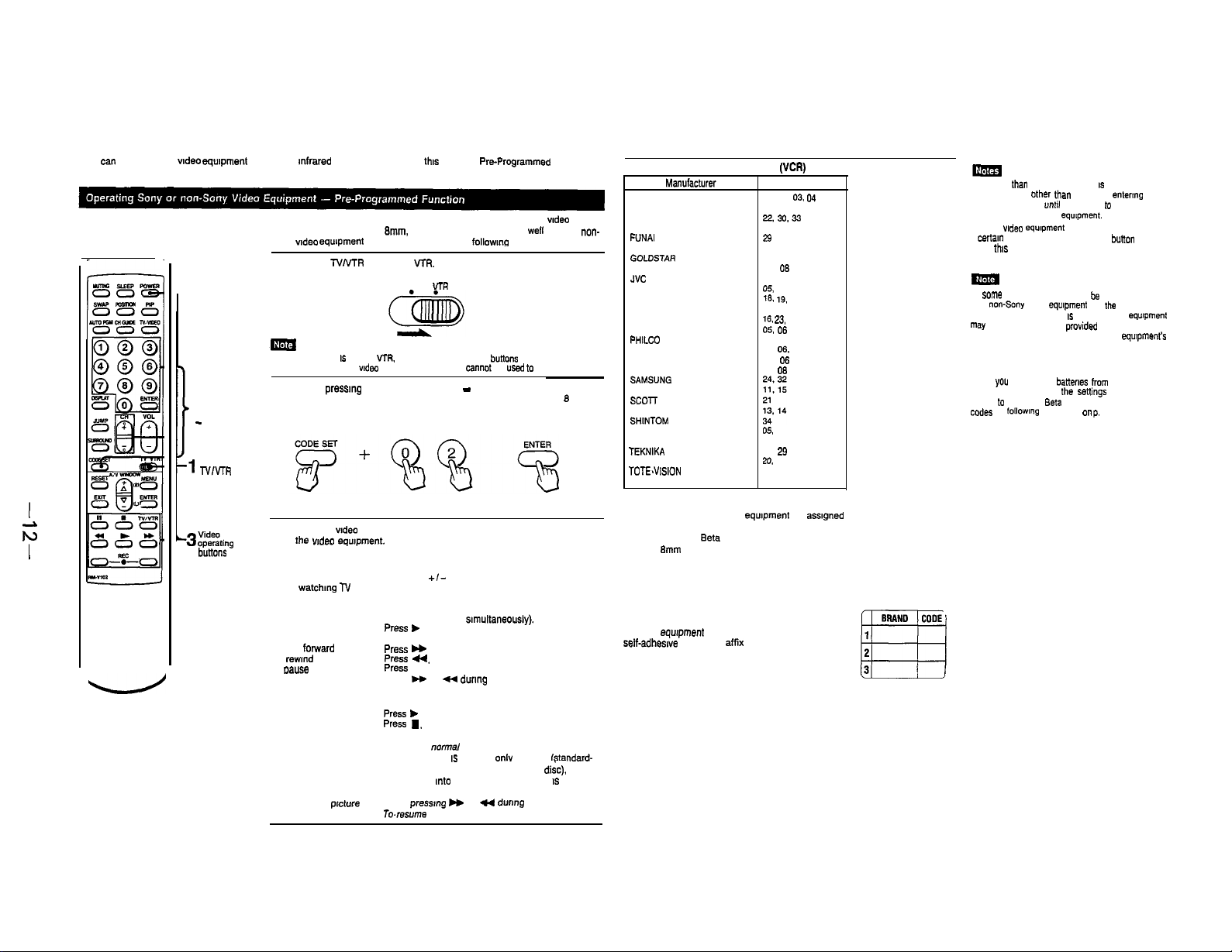
1-6. USING THE PRE-PROGRAMMED REMOTE COMMANDER
You can operate other wdeo
Commander.
equipment
2
0 - 9 buttons,
ENTER,
CODE SET
that has an
mfrared
remote detector with
With the supplied Remote Commander, you can operate a Sony wdeo
cassette recorder (Beta.
Sony wdeo
equipment
connected to your TV by
Set the TVMR selector to
1
When the selector IS set to VTR. the POWER and CH +I- bu,tons on the Remote
Commander function as wdeo operating buttons and canno, be used lo operate the TV.
While
pressmg
manufacturer’s code number. For example, to operate a Sony 0 mm
2
VCR, press 0, 2 and ENTER.
CODE SET, press the 0 - 9 buttons to enter the
th,s
supplied
Pre-Programmed
8mm,
VHS) or multi disc player as well as most
V-RX
TV VTR
followmg
the steps below.
Remote
I
71
TV/v-m
Manufacturers and Code Numbers
SONY
CANON
EMERSON
non-
FISHER
FUNAI
GENERAL ELECTRIC
GOLDSTAR
HITACHI
JVC
MAGNAVOX
MITSUBISHI
MULTITECH
NEC
PANASONIC
PHILCO
PHILIPS
OUASAR
RCA
SAMSUNG
SANYO
scol-r
SHARP
SHINTOM
SYLVANIA
SYMPHONIC
TEKNIKA
TOSHIBA
TOTE.V,SION
ZENITH
(l!CFf)
Code “umber
01. 02.
03. 04
05
22.30.33
10, 11. 12, 15
23
05. 06
25
07. 06
16
0%
06.09
16. 19. 26. 27
29
16. 23. 31
05. 06
05, 06
05. 06. 09
05. 06
07. 06
05. 06, 09
29
26. 26
20, 21
25
17
l If more than one code “umber
manufacturers Other than Sony, try e”ter,“g
them one by one. unbl you come 10 the
correct code for your equrpment.
l If the video equ,pme”, does no, have a
cerlal” function. the corresponding bunon
on ,h,s Remote Commander will no,
operate.
I” Some rare cases, you may not be able to operate
Your non-Sony video equlpme”, with
Remote Commander. This IS because your equrpment
may use a code that is not pmvided with this Remote
Commander. I” this case. please use the equrpment’s
own remote control unit.
CAUTION
When you remove the batteries
Remote Commander, all Ihe senings will
revert to the Sony
c”des
by
followlng
the steps on p. 30.
&,a
IS
listed far
the
supplied
from
the
setting. Reset the
‘3
$%ti”g
bu”ons
Use the
wdeo
the
wdeo
3
operating a VCR
To turn on or off Press POWER
To change channels Press CH
(when
watchmg l-V
programs through the
VCR’s tuner)
To record Press l (2 buttons s,multaneously).
To play
To stop Press n .
To fast
folward press H
To
rewmd
To
oause
To search the picture
forward and backward
Operating a Video Disc Player
To play
To stop
To pause
To search the
forward and backward
operating buttons on the Remote Commander to operate
eqmpment.
+/-
press t
the tape
prcture
Press u.
Press
II.
Press H or 4
Press *
Press
H.
Press II.
To resume normal playback, press age,“.
l
Th,s function ,s effective onlv for CAV fstandard-
play disc). With CLV (extended-play
TV will go
pressed.
Keep
pressrng H
To.resume
during
playback.
mto
the standby mode if II
or -
during
normal playback, release the button.
playback.
d&c).
IS
the
The code numbers for Sony
01 Beta, ED
02
8mm
03 VHS VCR
04 Video disc player
For your convenience
Write the manufacturer name and code number
for your
self-adheswe labels and
Commander for easy reference.
VCR
eqwpmenl
eqmpment
are
assIgned
Beta
VCR
onto one of the supplied
afffx
to the Remote
as follows:
-4
0 - 9 buttons
2-5
ENTER
I
[‘:,N”
-23
A/V WINDOW
+/-
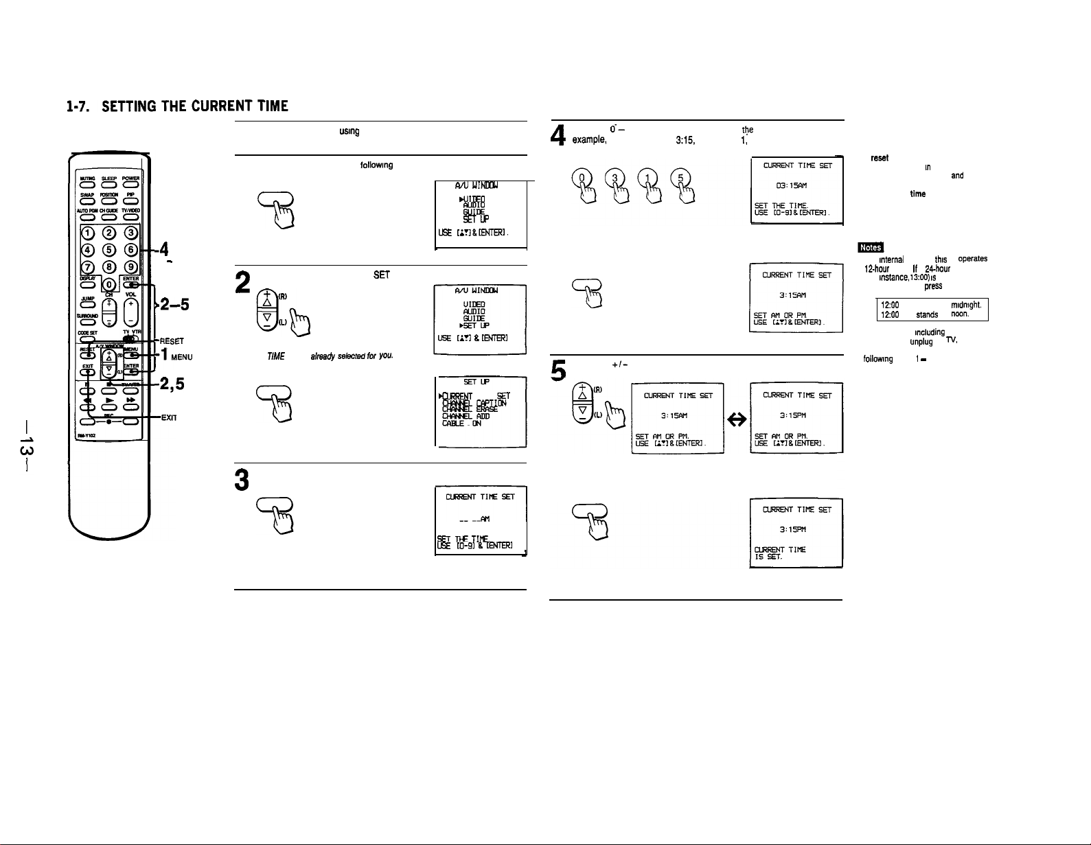
Set the current time before usmg the Timer-activated functions from the
GUIDE menu.
Press MENU to display the followmg screen.
1
I
MENU
Press the +I- button to select SET UP
AAJ
WINmJ
UJIDED
E%
SETUP
LEE ti~l&ENTER.
2
Press ENTER.
CURRENT TIME SET is alma@,’
ENTER
73
~&CM for YOU.
[A?1 & ENTER1
ClR=ENT
MF*NL
TIME
C@TIoN
Press the 6- 9 buttons and ENTER to enter the current time. For
exat’tIple. to set the time at 3:15, press 0,
4
digits.)
Press ENTER.
ENTER
Press the
+/-
button, to select AM or PM alternately.
§T
3. 1,
5. (You must
press
To clear the time setting
Press RESET.
4
To rest the time
Press RESET while m the CURRENT TIME
screen. an* repeat steps 4
To display the time
Set TIME DISPLAY ON/OFF.
To return to N mode
Press EXIT.
. The
mternal
clock of
this
tBhour cycle. If a w-hour cycle number
(for
instance. 13:OO) IS
cleared when you press ENTER.
1200 AM stands for
1200 PM
l All the settings
erased if you
failure occurs. Reset the current time by
follow”9 steps 1 - 5.
N ofw?&s on a
entered. it will be
sfands
for
m&ding
TIME SET will be
unplug
the N. or if a power
and
5.
mldmght.
“M)“.
3
Press ENTER.
ENTER
SET
TIE
TIf’E.
USE LO-91 B [ENrE!?I
Press ENTER.
ENTER
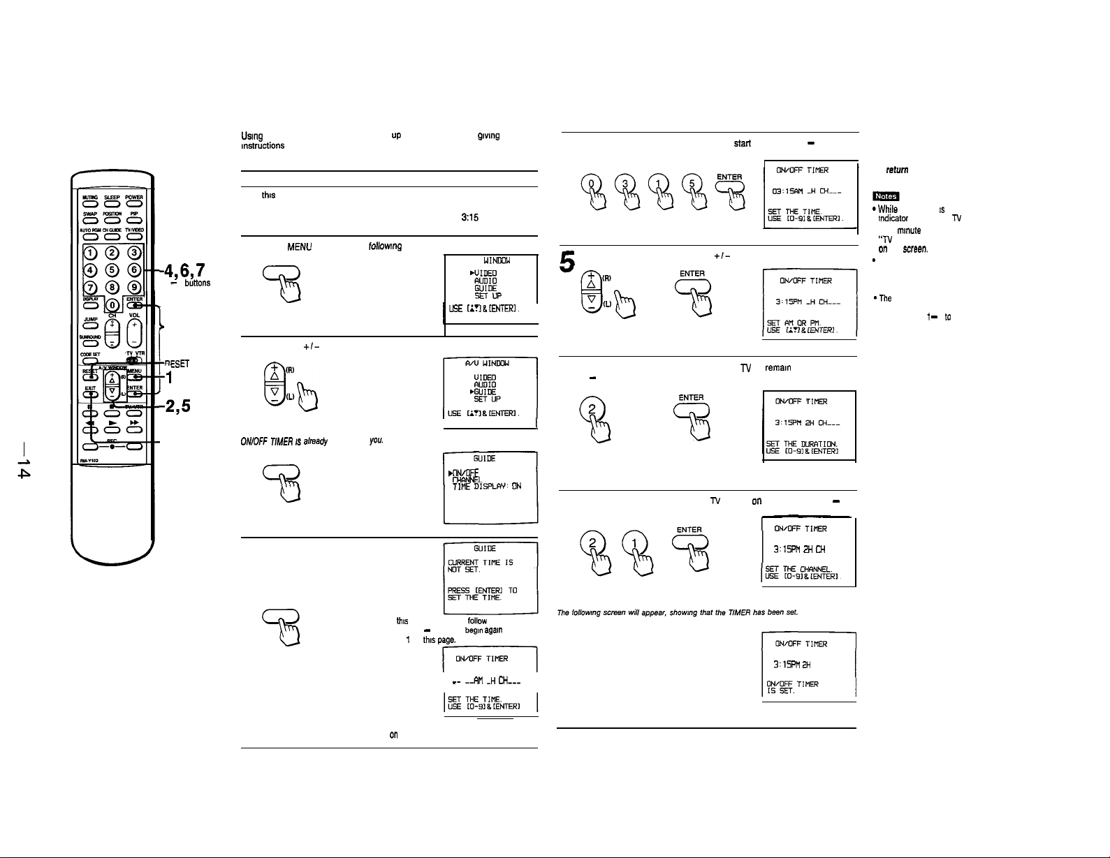
1-8. USING THE TIMER-ACTIVATED FUNCTIONS-GUIDE
Usmg
the GUIDE feature, you can call “p a” on-screen me”” g,“,“g
mstructions on how to use the timer-activated functions: ON/OFF TIMER,
CHANNEL BLOCK, AND TIME DISPLAY ON/OFF
Setting the ON/OFF TIMER
With this function you can sst your favorite program to appear on the screen
at the time that you set.
EXAMPLE: Set the timer to turn on the TV to channel 21 at 3:15 PM, for 2
hours.
Press
MENL’
-4,6,7
0 - 9
b"ttO"S
ENTER
I
-RESET
MENU
11
-23
A,"
WINDOW
+/-
-EXIT
to display the following screen
1
MENU
Press the
+/-
button to select GUIDE.
2
Press ENTER.
0,WO.V TlMER IS already selected for you.
ENTER
wu
1 USE
till&tENTER.1
L
.ON/OFF TIMER
cHANNEL BLOCK
TIME DISPLW: ON
WlNDm
Set the time that you want the TIMER to
must press 4 digits) and ENTER.
4
Select AM or PM by pressmg the
E
Set the duration of time that you want the TV to reman on. by pressmg
1 - 9 and ENTER.
6
start
by pressmg 0 - 9 (you
+I-
buttons. and prsss ENTER.
To clear the ON/OFF TIMER setting
Press RESET.
To
return
to N mode
Press EXIT.
*While
the TIMER 1s set. the TIMER
indicator
lamp an the TV will be lit.
l One mmute before the timer goes off. the
“TV WILL TURN OFF” display will appear
on
the
screen.
-
If you have not set the clock correctly, the
ON/OFF TIMER will not operate.
“Setting the CURRENT TIME” to set the
clock.
*The
TIMER setting will be erased if you
unplug the TV, or if a power failure occurs.
Repeat steps t - 7 tc reset the TIMER.
I
Set the channel that you want the
and ENTER.
7
l-V
to turn on to, by pressmg 0 - 9
3
Press ENTER.
ENTER
If tlxs screen appears,
on pp. 32 - 33. Then
step 1 on
th,s page.
If this screen appears, continue from step 4
on
the next page.
follow
begm agam
_-
-&II -H CH---
steps 3 - 5
from
J’lsml 2H CH
3’1SPM 2H
CH 21
21
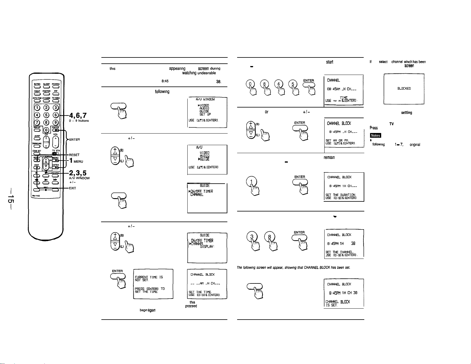
Setting CHANNEL BLOCK
Use this function to block a channel from appearmg on the screen durmg the
preset time, for Instance, to prevent children from watchmg undewable
programs.
EXAMPLE: Set CHANNEL BLOCK at
Press MENU to display the followmg screen.
1
MENU
Press the
+/-
button to select GUIDE.
2
F&R)
Press ENTER.
9145
PM, for one hour, on channel 38.
A/U WINDOW
i!lI:~
WUIDE
SET UP
Set the time that you want CHANNEL BLOCK to
0 - 9 (you must press 4 digit) and ENTER.
4
Select AM or PM by pressmg the
+/-
start
by pressmg
CHANNEL
08’45RM -H
SET THE TIVE.
LEE
IO-91 &
button, and press ENTER.
5
CH!Wf.EL BLOCK
Set the duration of time that you want the N to remam blocked (up to
9 hours). by pressmg 1 - 9 and ENTER.
6
BLOCK
CH---
[WTERI
If
you
Select
a
blocked, the BLOCKED screen will appear.
channel Which has
BLOCKED
bee”
El
TO clear the BLOCK settin
Press RESET,
TO ret”“, to IV mode
I
Press EXIT.
*
If you set a new CHANNEL BLOCK by
following
steps 1 - 7. the
will be erased.
l If you have not set the clock correctly.
CHANNEL BLOCK will not operate.
‘Setting the CURRENT TIME” to set
the clock.
origInal
setting
ENTER
73
Press the
3
Press ENTER.
+I-
buttons to select CHANNEL BLOCK.
If this screen appears, follow
steps 3 - 5.
The
begln agam
on this page.
from step 1
.ONMFF TIMER
Ci-WNEL BLOCK
TIME DISPLAY: ON
ON/OFF Tim
.CHFINNEL BLOCK
TINE
DISPLW:
ON
If this screen appears.
proceed to step 4 on
the next page.
Set the channel that you want to block, by pressmg 0 - 9 and ENTER.
7
E:4SPM
ENTER
cHANNEL8wcK
9:GPM 1H M 39
F!?EF ELocK
i
tH
CH 38
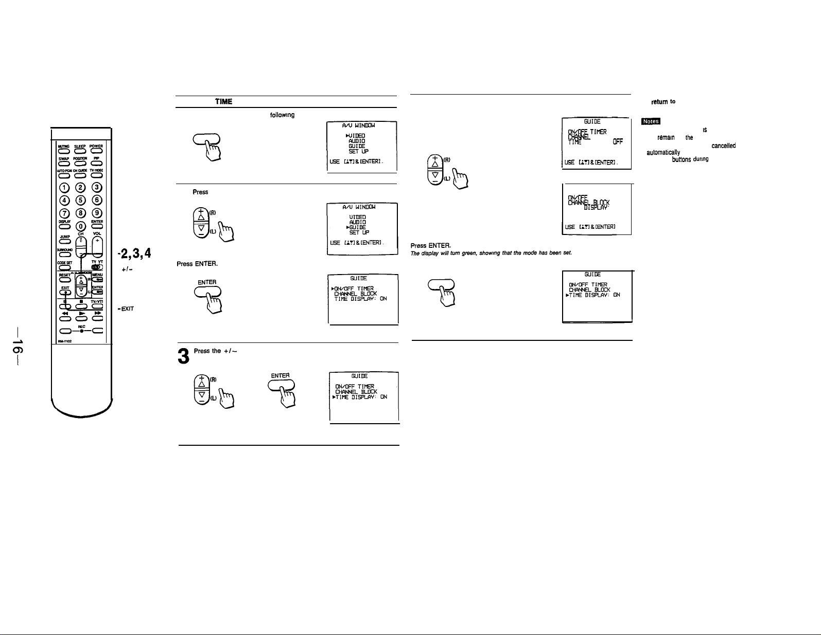
Setting the
1
TIME
DISPLAY
Press MENU to display the following screen.
MENU
Press the +I- button to select ON or OFF alternately.
(Display IS red)
4
OWOFF TINER
CHrwNEL BLOCK
TIME DISPLAY-
To
return
to N mode
Press EXIT.
ma
. when TIME DISPLAY IS set to ON. the time
OFF
will remam on
l The menu screens will be
aufomabcally alter 10 seconds it you do not
push any
fhe
butions
screen.
cancelled
durmg that time.
-2,3,4
A
,"
WINDOW
+I-
-1
MENU
-ENTER
-EXIT
press the +I- button to select GUIDE.
2
Press the
+I-
button and ENTER to select TIME DISPLAY.
3gb
WIDE
OWOFF TIMER
CWNNE BUICK
TIME
DEPLOY
ON
ENTER
53
q
pzq
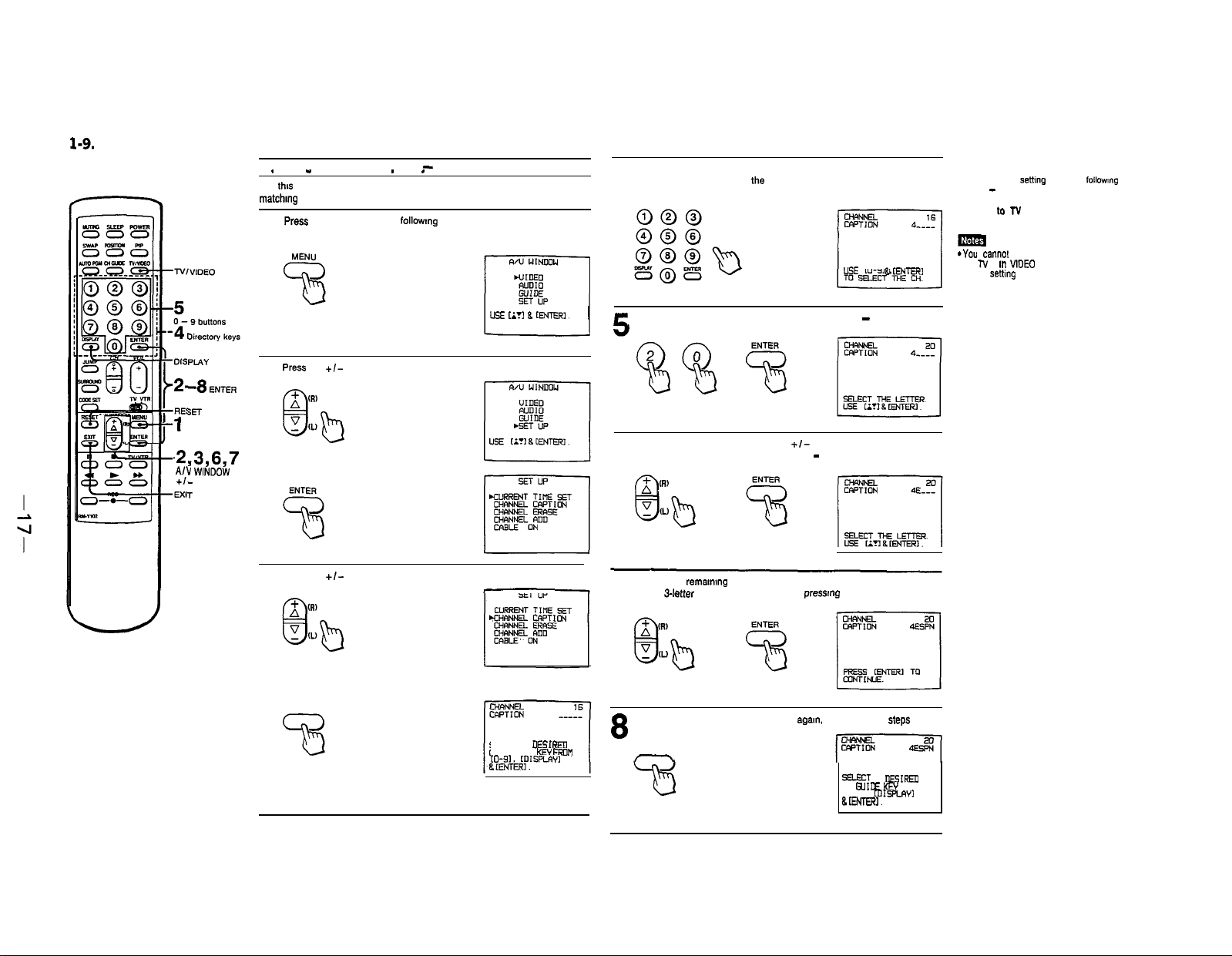
1-9.
USING CHANNEL CAPTION
’ 1
M ENU
ti
.2,3,6,7
A& WlNDOW
+,-
Caotionina the channel disolav
.
”
Use
thrs
feature to caption up to 12 channel number displays with the
matchmg
channel call letters. For example, caption channel 20 with ESPN.
PreSS
MENU to display the
-
CHANNEL CAPTION
. .
followmg
-~~~~~~
screen.
1
Press
the
+/-
button to select SET UP
2
Press ENTER.
Press the
+/-
button to select CHANNEL CAPTION.
3
~~
L!SE
Li?l 8 [ENTER].
Enter a directory (CHANNEL GUIDE) number for the
caption by pressmg one of
4
caption number 4. press 4.
r
Select the channel you want to caption by pressmg 0 - 9 and ENTER.
Select the first letter by pressmg the
Press + to advance alphabetically; press - to go back.
6
7
Select each
(For a
remammg
3-letter
caption. leave a space by
the
directory keys. For example, to set
+I-
button and ENTER
letter by repeating step 6.
pressmg
USE IO-91 & IENTER,
ENTER only.)
TO erase unneeded captions
Call the caption settmg screen by followmg
steps 1 - 4, and press RESET.
To return tr, N mode
Press EXIT.
mm
*You cannel use CHANNEL CAPTION while
the TV is ln WDEO or S VIDEO mode.
Before settmg captions, select TV mode by
pressmg TV/VIDEO.
Press ENTER.
ENTER
SELECT A
MSIREII
CH GUIDE
[O-91. m1sPLw1
KC/ FROM
To set the next caption, press ENTER
step 4.
8
ENTER
-
agam.
and repeat the
.step.s
from
SELECT A
DaIREIl
CH GUIDE KEY PROM
to-91. KlIsRAYI
BENTERI.
1
CH GUIDE
2
Directory
keys
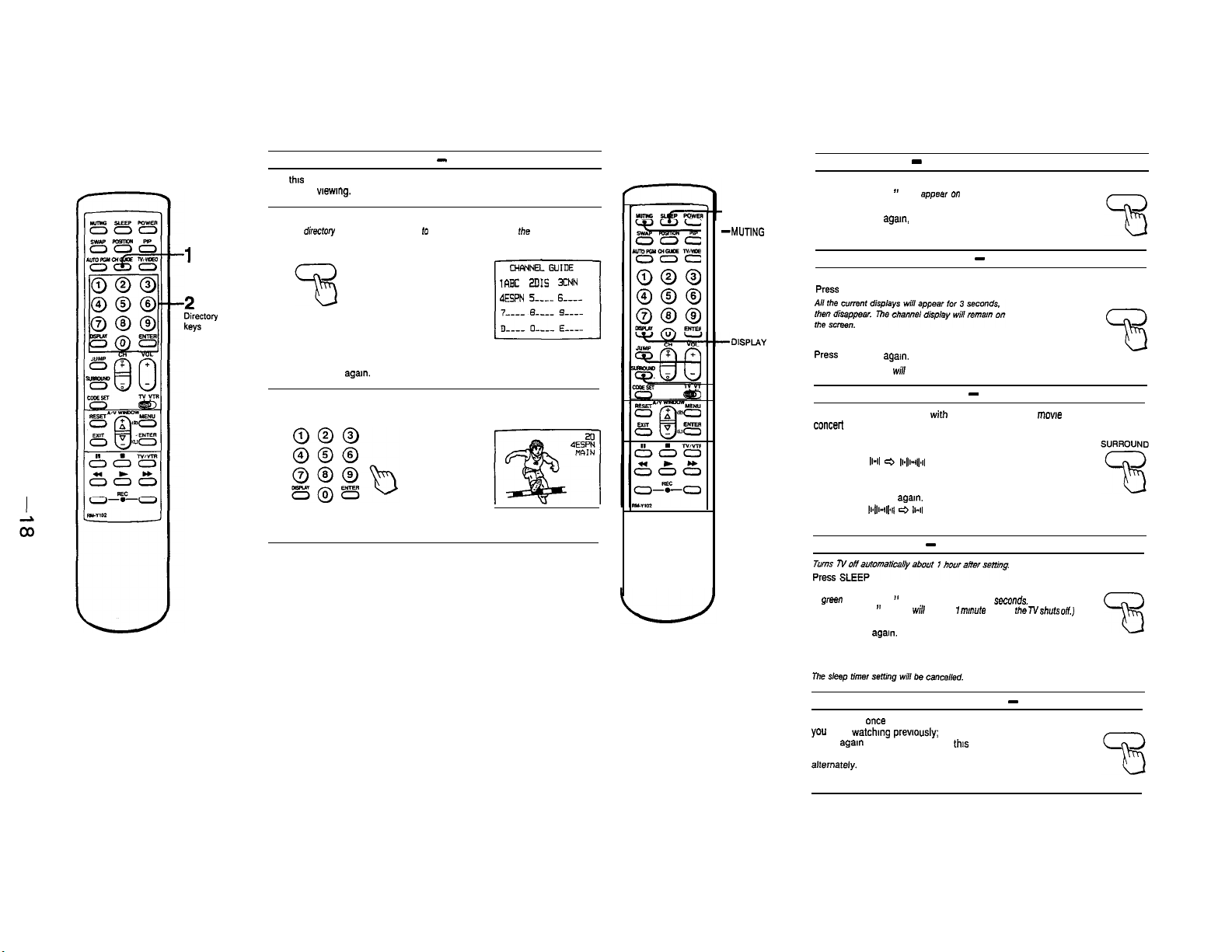
Viewing the captioned channels - CHANNEL GUIDE
Use
this
feature to display the captions you have set, and to select a channel
directly for wewmg.
Press CH GUIDE.
A dimcfo!y appears. corresponding to the directory keys on the Remote
1
Commander.
CH GUIDE
10X
ZDIS XNN
IESPN 5-e 6--w-
To cancel the CHANNEL GUIDE screen
Press CH GUIDE
Press the directory key of the channel you want to watch.
aga”.
2
l-10.
ENJOYING OTHER USEFUL FEATURES
Muting the sound - MUTING
Press MUTING.
-SLEEP
--MUTING
-JUMP
-SURROUND
The display “MUTING ” will
To restore the sound
Press MUTING age,“, or press VOL+
Keeping the channel displayed
To display the channel
press
DISPLAY.
To cancel the display
press DISPLAY again.
The channel display wiff disappear.
Listening to surround sound
Gives sound reproduction
concerl
hall.
To set
Press SURROUND
The display
the screen for a few seconds.
To cancel
Press SURROUND agal”.
The display l14141 e
few seconds.
11-11 r=, 1~4lW11
Usmg the sleep timer - SLEEP
appea,
on the screen.
-
-
SURROUND
with
the atmosphere of a mowe theater or a
will appear on
II-II
will appear for a
MUTING
DISPLAY
DISPLAY
A green “SLEEP ON ” display appears for a few seconds.
(A red “SLEEP ” display
To cancel the setting
Press SLEEP
A green “SLEEP OFF” display appears for a few seconds.
OR
Turn the TV off.
agam.
will
appear 1
m~lufe
before
the N shuts
Switching quickly between 2 channels - JUMP
Press JUMP
you
JUMP
feature to keep track of two programs
alternately.
once
were
watching previously;
agam
to switch back. Use
to recall the channel
press
this
SLEEP
oft)
23
JUMP
 Loading...