

Sony KZ-42TS1U, KZ-32TS1U Owner’s Manual
_____'_,., • "I_._H_!._....._,_ • •'_9_ _
r
II ÷ II
÷
WARNING
To Reduce the risk of fire or shock hazard,
do not expose the TV to rain or moisture,
RiSK OF ELECTRIC SHOCK
DO NOT OPEN
ATTENTION
RISQUE DE CHOC ELECTRiQUE,
NE PAS OUVRiR
PRECAUCION
RtESGO DE CHOQUE ELECTRICO
NO ABRIR
CAUTION : TO REDUCE THE RiSK OF ELECTRIC SHOCK,
DO NOT REMOVE COVER (OR BACK)
NO USER-SERVICEABLE PARTS iNSiDE
REFER SERVICING TO QUAUFtED SERVtCE PERSONNEL
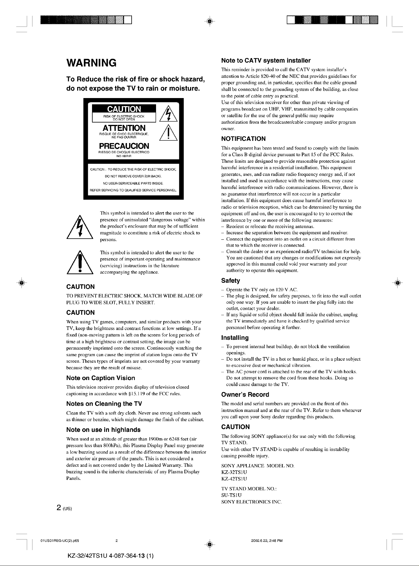
This symbol is intended to alert the user to the
presence of uninsulated "dangerous voltage" within
the product's enclosure that may be of sufficient
magnitude to constitute a risk of electric shock to
persons.
This symbol is intended lo alert the user Io the
presence of important operating and maintenance
(servicing) instructions in the lileratare
accompanying the appliance.
CAUTION
TO PREVENT ELECTRIC SHOCK, MATCH WIDE BLADE OF
PLUG TO WIDE SLOT, FULLY INSERT.
CAUTION
When using TV games, computers, and similar products with your
TV, keep tl_e brightness and contrast functions at low .settings. If a
fixed (non-moving pattern is left on the screen for long periods of
time at a high brightness or contrast selting, the image can be
permanently imprinted onto the screen. Continuously watching the
same program can cause the imprint of station logos onto the TV
screen. Theses types of imprints are not covered by your warranty
because they are the result of misuse.
Note on Caption Vision
This television receiver provides display of television closed
captioning in accordance with §15.119 of the FCC rules.
Notes on Cleaning the TV
Clean the TV with a soft dry cloth. Never use strong solvents such
as thinner or benzine, which might damage the finish of the cabinet.
Note on use in highlands
When used at an altitude of greater than 1900m or 6248 feet (air
pressure less than 8fXlhPa), this Plasma Display Panel may generate
a low buzzing sound as a result of the difference between the interior
and exterior air pressure of the panels. This is not considered a
defect and is not covered under by the Limited Warranty. This
buzzing sound is the inherite characteristic of any Plasma Display
Panels.
2(us)
Note to CATV system installer
This reminder is provided to call the CATV system installer's
attention to Article 820-40 of the NEC that provides guidelines for
proper grounding and, in particular, specifies that the cable ground
shall be connected to the grounding system of the building, as close
to the point of cable entry as practical.
Use of this television receiver for other than private viewing of
programs broadcast on UHF, VHF, transmitted by cable companies
or satellite for the use of d_e general public may require
authorization from the broadcaster/cable company and/or program
owner.
NOTIFICATION
This equipment has been tested and lbund to comply with the limits
for a Class B digital device pursuant to Part 15 of the FCC Rules.
These limits are designed to provide reasonable protection against
harmful interference in a residential installation. This equipment
generates, uses, and can radiate radio frequency energy and, if not
installed and used in accordance wid_ the instructions, may cause
harmful interference with radio communications. However, there is
no guarantee that interference will not occur in a particular
installation. If this equipment does cause harmful interference to
radio or television reception, which can be determined by turning the
equipment off and on, the user is encouraged to try lo correct the
inted?rence by one or more of the following measures:
- Reorient or relocate the receiving antennas.
- Increase the separation between d_e equipment and receiver.
- Connect the equipment into an outlet on a circuit different from
thai to which the receiver is connected.
- Consult the dealer or an experienced radiofFV technician for help.
You are cautioned thai any changes or modifications not expressly
approved in this manual could void your warranty and your
authority to operate this equipment.
Safety
- Operate the TV only on 120 V AC.
- The plug is designed, for safety purposes, to fit into the wall outlet
only one way. If you are unable to insert the plug fully into the
outlet, contact your dealer.
- if any liquid or solid object should fall inside the cabinet, unplug
the TV immediately and have it checked by qualified service
personnel before operating it l)rther.
Installing
- To prevent internal heat buildup, do not block the ventilation
openings.
- Do not install the TV in a hot or humid place, or in a place subject
to excessive dust or mechanical vibration.
- The AC power cord is attached to the rear of the TV with hooks.
Do not attempt to remove the cord from these hooks. Doing so
could cause damage to the TV.
Owner's Record
The model and serial numbers ave provided on the front of dfis
instruction manual and at the rear of the TV. Ret_r to them whenever
you call upon your Sony dealer regarding this products.
CAUTION
The following SONY appliance(s) for use only with the following
TV STAND.
Use with other TV STAND is capable of resulting in instability
causing possible injury.
SONY APPLIANCE MODEL NO.
KZ-32TS1U
KZ-42TS 1U
TV STAND MODEL NO.:
SU-TSIU
SONY ELECTRONICSINC.
÷
I I 01US01REG-UC(2) p65 2
KZ-32/42TS1U 4-087-364-13 (1)
÷
2002.622, 2:48 PM
II
II ÷ II
Table of Contents
Table of Contents
÷
Installing and Connecting the TV
Unpacking .......................................................... 4
Inserting Batteries into the Remote Control ... 4
Preventing the TV from Falling Down ............ 4
Connector Types ................................................ 5
Identifying Front and Rear Connectors .......... 6
Basic Connections (Connecting Cable TV or
Antenna) ........................................................ 7
Connecting directly to cable or an antenna7
Cable box connections .............................. 7
Connecting a VCR and Cable .......................... 8
Connecting a Satellite Receiver ........................ 9
Connecting a Satellite Receiver with a VCR. 10
Connecting an Audio Receiver ....................... 11
Connecting a DVD Player with Component
Video Connectors ....................................... 12
Connecting a DVD Player with A/V
Connectors .................................................. 13
Connecting a Digital TV Receiver ................. 14
Connecting a Sub Woofer ............................... 15
Connecting an RGB Equipment .................... 16
Setting the Channels ........................................ 17
Selecting the On-screen Menu Language ...... 19
Setting the Video Inputs .................................. 29
Operating Video Equipment with Your TV
Remote Control .......................................... 30
Programming the remote control ............ 30
Operating optional equipment ................. 32
Using Favorite Channels ................................. 33
Setting your favorite channels ................. 33
Watching Favorite Channel .................... 34
Adjusting Your Setup
Adjusting the Picture Size/Position ................ 35
Using the Picture Control Mode Option ....... 36
Using the Sound Control Option .................... 38
Selecting Stereo or Bilingual Programs ......... 40
Using the Parental Control Feature ............... 40
Activating the Parental Control feature .. 41
Selecting a Custom Rating ...................... 43
What the Ratings Mean .................................. 45
÷
Ratings in the U.S.A ............................... 45
Ratings in Canada ................................... 46
Adjusting Advanced AV Setting Options ...... 48
Using the Timer
Watching the TV
Watching the TV ............................................. 20
Watching with closed caption ................. 21
Enjoying High-quality Pictures and Sounds. 22
Selecting the Picture Mode ............................. 23
Selecting the Effect Mode ............................... 24
Saving the Power Consumption ..................... 25
Using the Wide Screen Mode ......................... 26
Changing the Wide Screen Mode
automatically ...................................... 26
Changing the Wide Screen Mode
manually ............................................. 27
Changing the Wide Setup ....................... 27
Turning Off the TV Automatically ................ 51
Setting the Current Time ................................ 52
Controlling Power On/Off Automatically ..... 53
Additional Information
Troubleshooting ............................................... 55
Self-diagnosis function ........................... 55
Trouble symptoms and remedies ............ 56
Specifications ................................................... 58
Index ................................................................. 59
(us)3
I I 01USO2TOC*UC(3) p65 ÷
2002622, 3:14 PM
II
KZ-32/42TS 1U 4-087-364-13 (1)
Unpacking
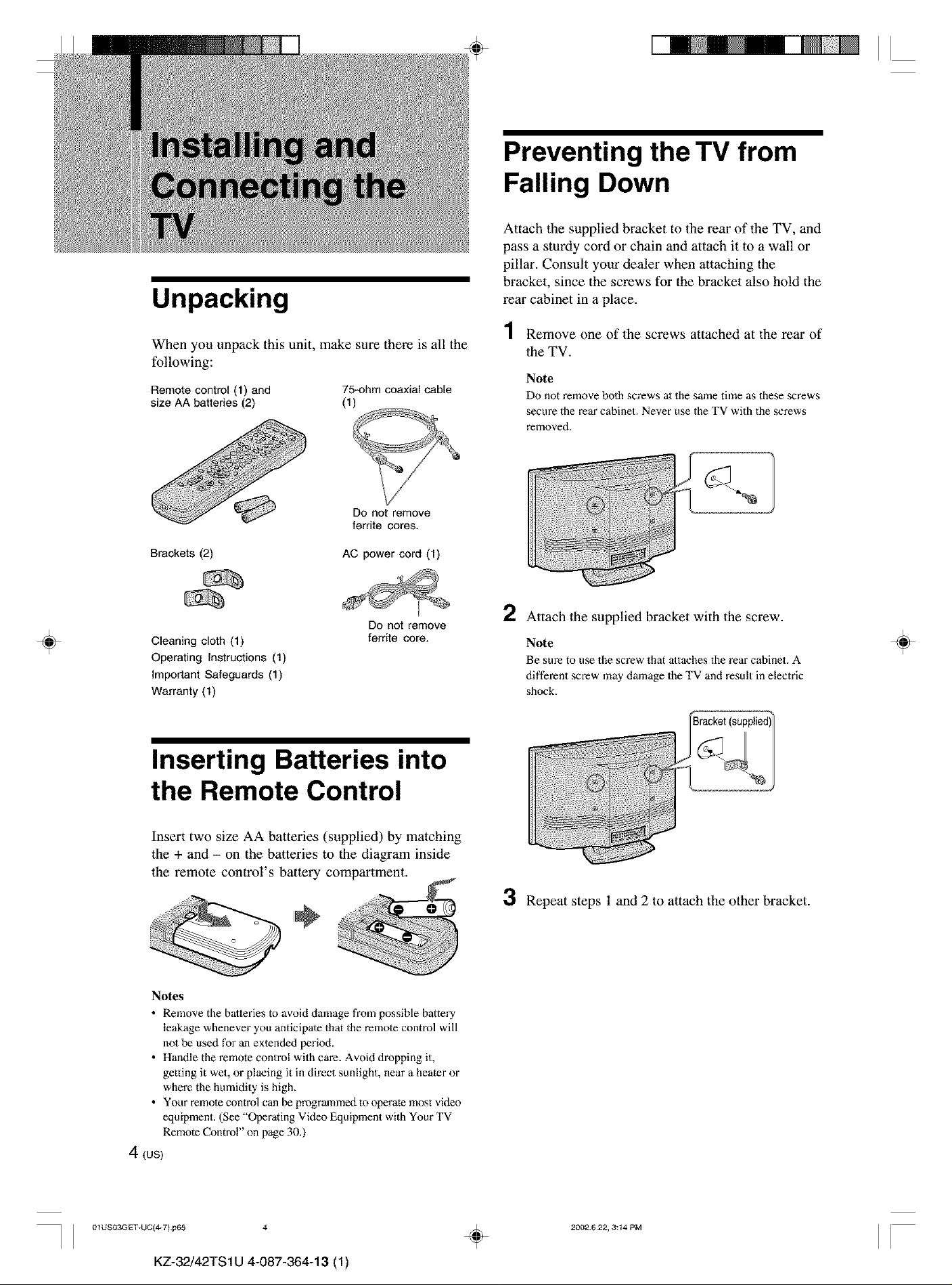
When you unpack this unit, make sure there is all the
following:
Remotecontrol(1) and 75-ohmcoaxialcable
size AA batteries(2) (1)
II
Preventing the TV from
Falling Down
Attach the supplied bracket to the rear of the TV, and
pass a sturdy cord or chain and attach it to a wall or
pillar. Consult your dealer when attaching the
bracket, since the screws for the bracket also hold the
rear cabinet in a place.
4
/ Remove one of the screws attached at the rear of
the TV.
Note
Do not remove bolh screws al the same time as these screws
secure the rear cabinet. Never use the TV with the screws
removed.
÷
Do not remove
ferrite cores.
Brackets (2)
Cleaning cloth (1)
Operating Instructions (1)
Important Safeguards (1)
Warranty (1)
AC power cord (1)
Do not remove
ferrite core.
Inserting Batteries into
the Remote Control
Insert two size AA batteries (supplied) by matching
the + and - on the batteries to the diagram inside
the remote control's battery compartment.
2 Attach the supplied bracket with the screw.
Note
Be sure to use the screw that attaches the rear cabinet. A
different screw may damage the TV and result in electric
shock.
3 Repeat steps 1 and 2 to attach the other bracket.
÷
Notes
• Remove the batteries to avoid damage from possible battery
leakage whenever you anticipate that the remote control will
nol be used for an extended period.
• Handle the remote control with care. Avoid dropping it,
getting it wet, or placing it in direct sunlight, near a heater or
where the humidity is high.
• Your remote control can be programmed to operate most video
equipment. (See "Operating Video Equipment with Your TV
Remote Control" on page 30.)
4 (us)
] 01US03GET+UC(4_7) p65 4
KZ-32/42TS1U 4-087-364-13 (1)
÷
2002.622, 3:14 PM
II
II ÷ II
Installing and Connecting the TV
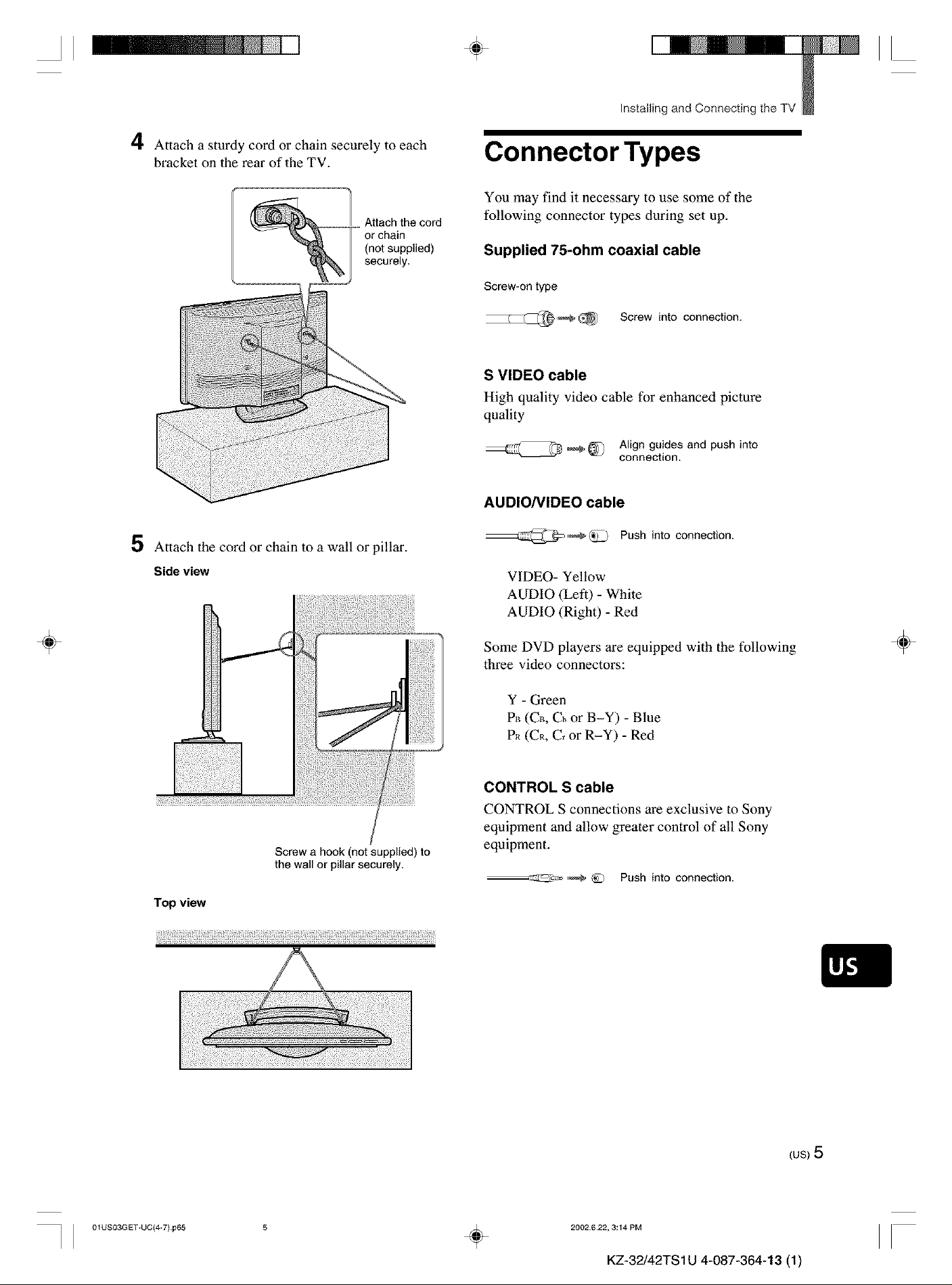
4 Attach a sturdy cord or chain securely to each
bracket on the rear of the TV.
5 Attach the cord or chain to a wall or pillar.
Connector Types
You may find it necessary to use some of the
following connector types during set up.
Supplied 7f-ohm coaxial cable
Screw-on type
Screw into connection.
S VIDEO cable
High quality video cable for enhanced picture
quality
Align guides and push into
connection.
AUDIO/VIDEO cable
Push into connection.
÷
Side view
Screw a hook (not supplied) to
the wall or pillar securely.
Top view
i!fli;!!!i_i¸il;!i¸ii!¸iii¸!ili;_ili!i¸i!_:iii!i¸i!_:iii!i¸i!_:iii!i¸i!_:iii!i¸i!_:iii!i¸i!_:iii!i¸i!_:iii!i¸i!_:iii!i¸i!_:iii!i¸i!_:iii!i¸i!_:iii!i¸i!_:iii!i¸i!_:iii!i¸i!_:iii!i¸i!_:iii!i¸i!_:iii!i¸i!_:iii!i¸i!_:iii!i¸i!_:iii!i¸i!_:iii!i¸i!_:iii!i¸i!_:iii!i¸i!_:iii!i¸i!_:iii!i¸i!_:iii!i¸i!_:iii!i¸i!_:iii!i¸i!_:iii!i¸i!_:iii!i¸i!_:iii!i¸i!_:iii!i¸i!_:iii!i
VIDEO- Yellow
AUDIO (Left) - White
AUDIO (Right) - Red
Some DVD players are equipped with the following
three video connectors:
Y - Green
P_ (CB, Cb or B-Y) - Blue
P_ (CR, C, or R-Y) - Red
CONTROL S cable
CONTROL S connections are exclusive to Sony
equipment and allow greater control of all Sony
equipment.
--_:_2Z_ ,_ @ Push into connection.
÷
] 01US03GET+UC(_7) p65 ÷
(us)5
2002622, 3:14 PM
II
KZ-32/42TS 1U 4-087-364-13 (1)
II
÷ II
_ Installing and Connecting the TV
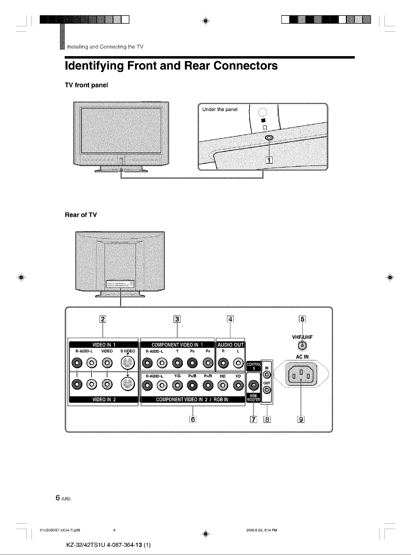
Identifying Front and Rear Connectors
TV front panel
Under the panel _
O
÷
Rear of TV
_oooooooooo _j
oo_oooooooo°
÷
AC IN
6 (us)
I I 01US03GET+UC(4W)p65 6
KZ-32/42TS1U 4-087-364-13 (1)
÷
2002.622, 3:14 PM
II
II ÷ II
Installing and Connecting the TV
[]
Headphones jack
Connects to your headphones.
If your headphones do not match the jack, use a
suitable plug adaptor (not supplied).
Basic Connections
(Connecting Cable TV or
÷
[]
VIDEO IN 1, 2 (pages 8 - 10, 13)
Connects to the output jacks of your VCR or
other video equipment.
[]
COMPONENT VIDEO IN 1 (pages 12, 14)
Connects to the component video (Y, P,_,P_0 and
audio (L/R) output jacks of your DVD player or
digital TV receiver.
[]
AUDIO OUT (page 11)
Connects to the input jacks of your audio
equipment.
[]
VHF/UHF (pages 8 - 10)
Connects to your VHF/UHF antenna or cable.
[]
COMPONENT VIDEO IN 2/RGB IN
(page 16)
Y/G, PdB, P_ input jacks:
Connects to the component video (Y/CdCR, Y/
B-Y/R-Y or Y/PdP_) output jacks of your DVD
player, or video output jacks of your RGB
equipment.
AUDIO (LfR) input jacks:
Connects to the audio output jacks of your DVD
player or RGB equipment.
HD/VD input jacks:
Connects to the synchronized signal output .jacks
of your RGB equipment.
Antenna)
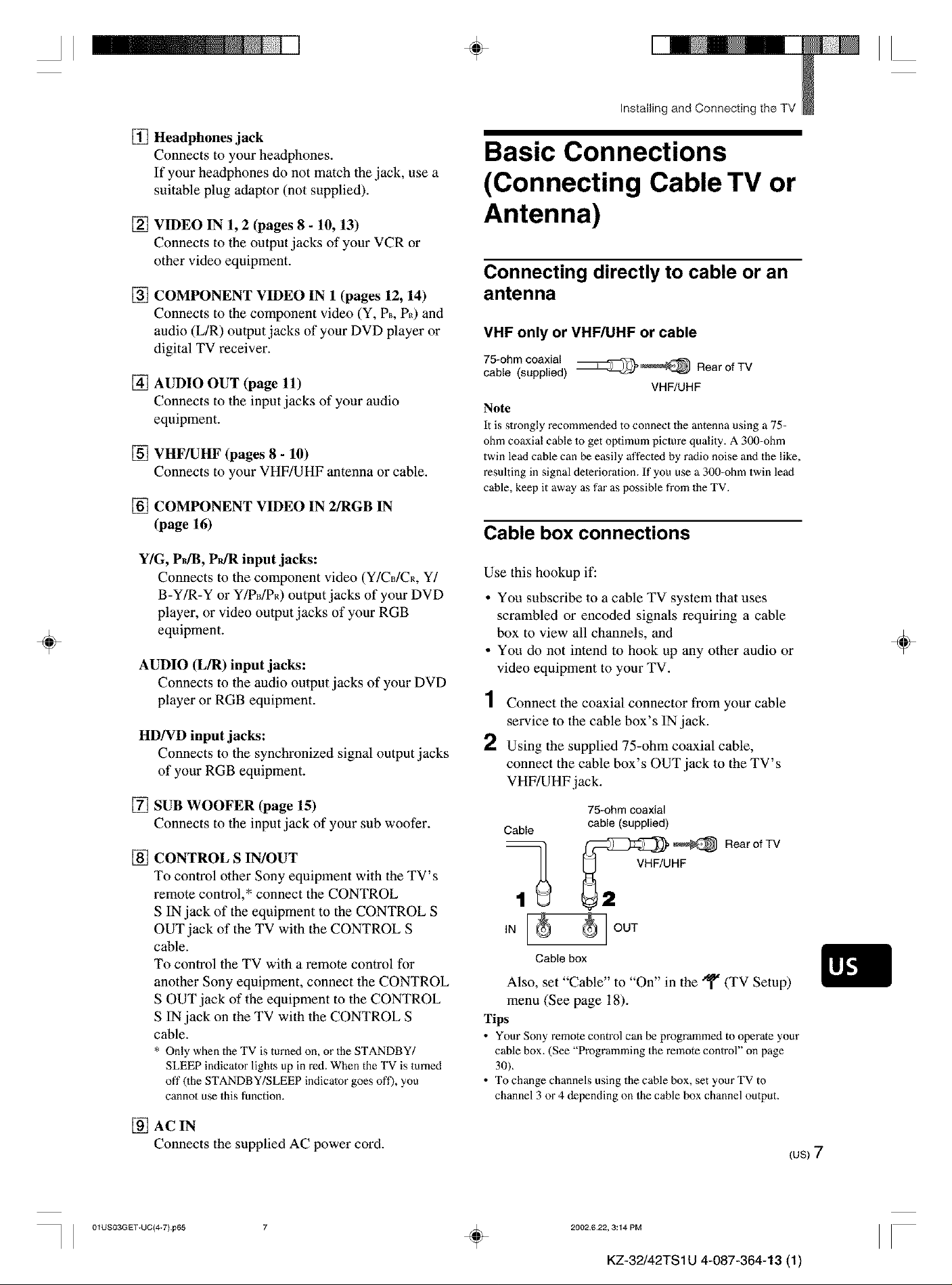
Connecting directly to cable or an
antenna
VHF only or VHF/UHF or cable
75-ohm coaxial
cable (supplied) _'_ Rear of TV
VHF/UHF
Note
It is slrongly recommended to connect the antenna using a 75-
ohm coaxial cable 1o get optimum picture quality. A 300-ohm
twin lead cable can be easily affecled by radio noise and the like,
resulting in signal deterioration. If you use a 300-ohm twin lead
cable, keep it away as far as possible from the TV.
Cable box connections
Use this hookup if:
• Yon subscribe to a cable TV system that uses
scrambled or encoded signals requiring a cable
box to view all channels, and
• Yon do not intend to hook up any other audio or
video equipment to your TV.
1 Connect the coaxial connector from your cable
service to the cable box's IN.jack.
2 Using the supplied 75-ohm coaxial cable,
connect the cable box's OUT jack to the TV's
VHF/UHF.jack.
÷
[] SUB WOOFER (page 15)
Connects to the input jack of your sub woofer.
[] CONTROL S IN/OUT
To control other Sony equipment with the TV's
remote control,* connect the CONTROL
S IN jack of the equipment to the CONTROL S
OUT jack of the TV with the CONTROL S
cable.
To control the TV with a remote control for
another Sony equipment, connect the CONTROL
S OUT jack of the equipment to the CONTROL
S IN jack on the TV with the CONTROL S
cable.
* Only when the TV is turned on, or the STANDBY/
SLEEP indicator lights up in red. When the TV is turned
off 0he STANDBY/SLEEP indicator goes oft'), you
cannot use this function.
[] AC IN
Connects the supplied AC power cord.
75-ohm coaxial
Cable
IN _ OUT
Cablebox
Also, set "Cable" to "On" in the _ (TV Setup)
menu (See page 18).
Tips
• Your Sony remote control can be programmed to operate your
cable box. (See "Programming the remote control" on page
30).
• To change channels using the cable box, set yourTV to
channel 3 or 4 depending on the cable box channel output.
cable (supplied)
_[3:_ ,_ Rear of TV
_ VHF/UHF
(us)7
I I 01USO3GET+UC(_7) p65 ÷
2002622, 3:14 PM
II
KZ-32/42TS 1U 4-087-364-13 (1)
II
_ Installing and Connecting the TV
4,
II
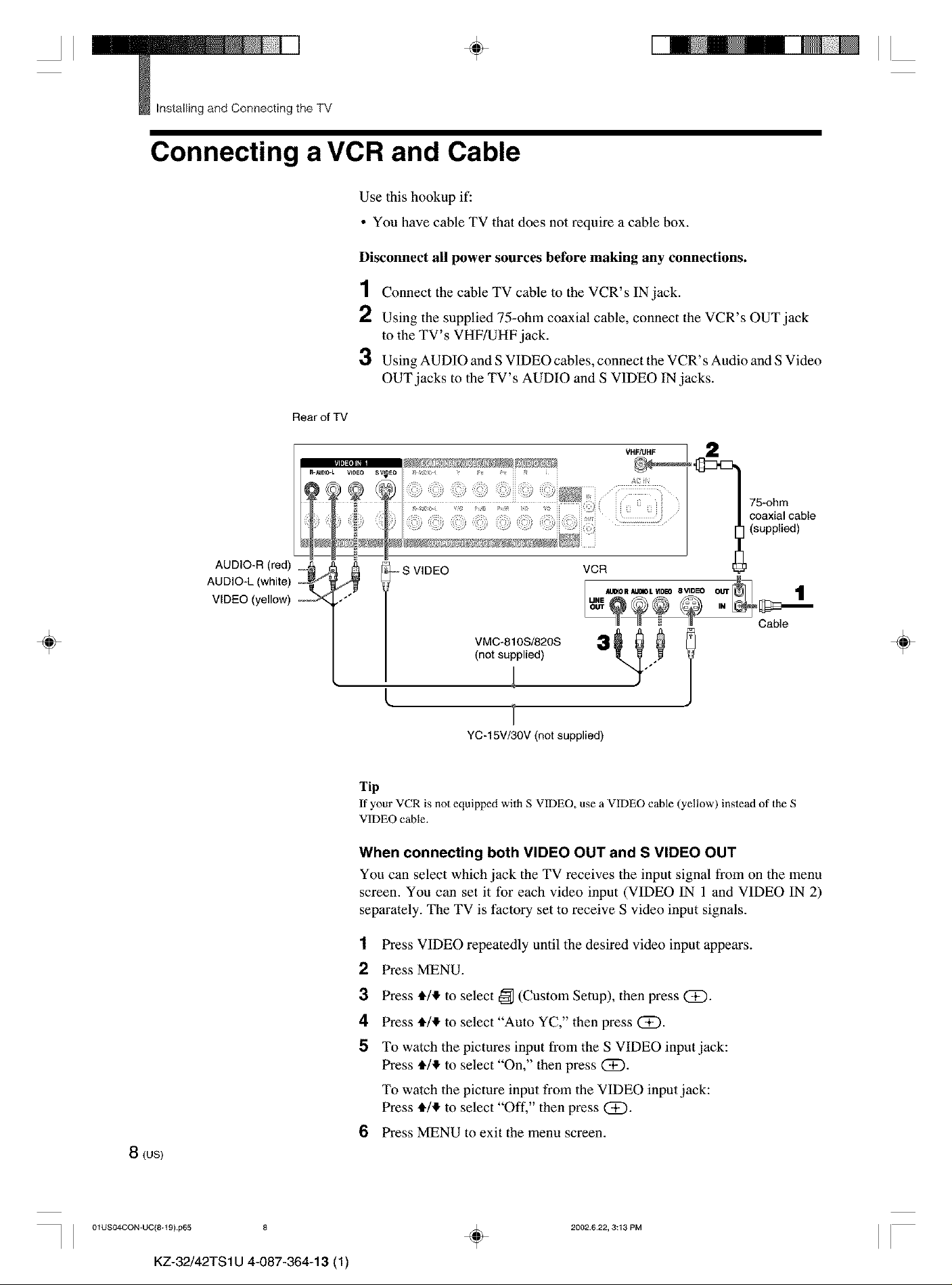
Connecting a VCR and Cable
Use this hookup if:
• You have cable TV that does not require a cable box.
Disconnect all power sources before making any connections.
1 Connect the cable TV cable to the VCR's IN jack.
2 Using the supplied 75-ohm coaxial cable, connect the VCR's OUT jack
to the TV' s VHF/UHF jack.
3 Using AUDIO and S VIDEO cables, connect the VCR's Audio and S Video
OUT jacks to the TV's AUDIO and S VIDEO IN jacks.
Rear of TV
÷
AUDIO-R (red) _._ _
AUDIO-L (white) i_
VIDEO (yellow) ,/"
75-ohm
coaxial cable
(supplied)
- S VIDEO
VMC-810S/820S
(not supplied)
YC-15V/30V (not supplied)
Tip
If your VCR is not equipped with S VIDEO, use a VIDEO cable (yellow) instead of the S
VIDEO cane.
When connecting both VIDEO OUT and S VIDEO OUT
You can select which jack the TV receives the input signal from on the menu
screen. You can set it for each video input (VIDEO IN 1 and VIDEO IN 2)
separately. The TV is factory set to receive S video input signals.
VCR
AUtO R AUOIOL _DEO 8 VIDE_ OUT
MNE
1
Cable
÷
8(us)
I I 01USO4CON_UC(8+t 9) p65 8
KZ-32/42TS1U 4-087-364-13 (1)
1
Press VIDEO repeatedly until the desired video input appears.
2
Press MENU.
3
Press 4,/,!, to select _ (Custom Setup), then press (i).
4
Press 4,/,!, to select "Auto YC," then press (2D.
5
To watch the pictures input from the S VIDEO input jack:
Press 4,/,!, to select "On," then press (2D.
To watch the picture input from the VIDEO input jack:
Press 4,/,!, to select "Off," then press (Z).
6
Press MENU to exit the menu screen.
2002.622, 3:13 PM
÷
II
II ÷ II
Installing and Connecting the TV
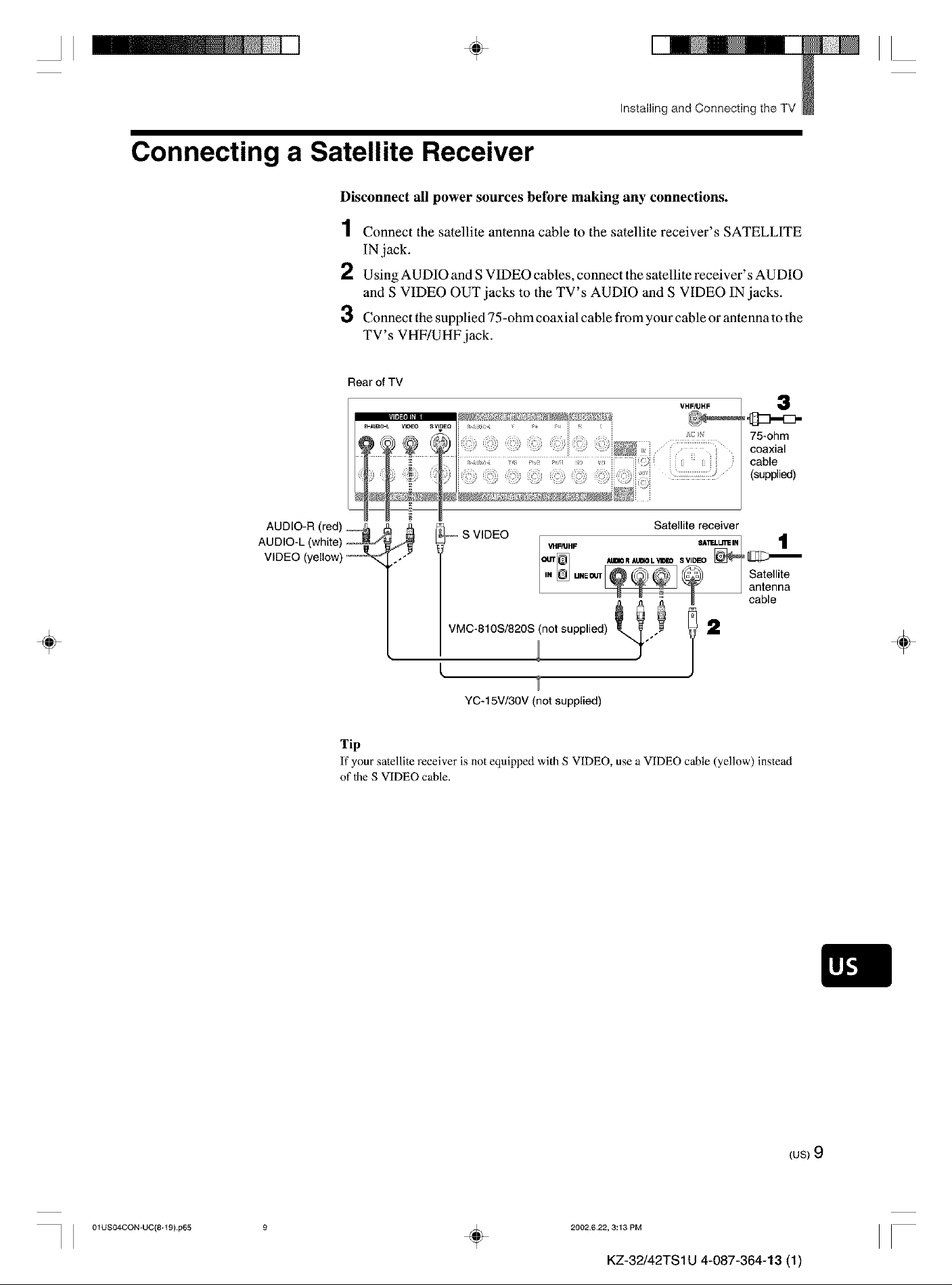
Connecting a Satellite Receiver
Disconnect all power sources before making any connections.
1 Connect the satellite antenna cable to the satellite receiver's SATELLITE
IN jack.
2 Using AUDIO and S VIDEO cables, connect the satellite receiver's AUDIO
and S VIDEO OUT jacks to the TV's AUDIO and S VIDEO IN jacks.
3 Connect the supplied 75-ohm coaxial cable from your cable or antenna to the
TV' s VHF/UHF jack.
Rear of TV
VHF_HF
3
75-ohm
coaxial
cable
(supplied)
÷
÷
YC-15V/30V (not supplied)
Tip
If your satellite receiver is not equipped with S VIDEO, use a VIDEO cane (yellow) instead
of 1heS VIDEO cable.
I I 01USO4CON-UC(8+t 9} p65 ÷
(us)9
2002622, 3:13 PM
II
KZ-32/42TS 1U 4-087-364-13 (1)
II
_ Installing and Connecting the TV
4,
II
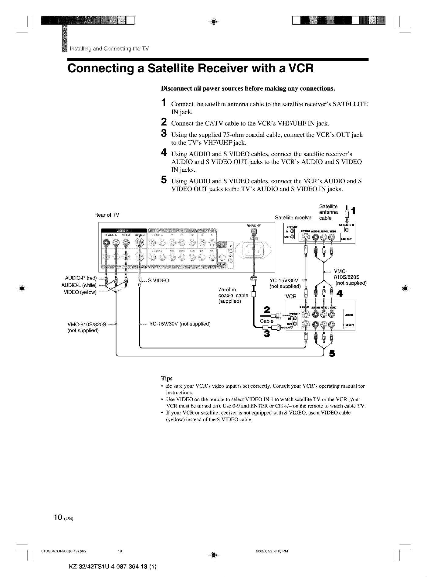
Connecting a Satellite Receiver with a VCR
Disconnect all power sources before making any connections.
1 Connect the satellite antenna cable to the satellite receiver's SATELLITE
IN jack.
2 Connect the CATV cable to the VCR's VHF/UHF IN jack.
3 Using the supplied 75-ohm coaxial cable, connect the VCR's OUT jack
to the TV's VHF/UHF jack.
4 Using AUDIO and S VIDEO cables, connect the satellite receiver's
AUDIO and S VIDEO OUT jacks to the VCR's AUDIO and S VIDEO
IN jacks.
5 Using AUDIO and S VIDEO cables, connect the VCR's AUDIO and S
VIDEO OUT jacks to the TV's AUDIO and S VIDEO IN jacks.
÷
Rear of TV
AUDIO-R (red) _ J
AUDIO.L (white) ,--_
VIDEO (yellow) _ _
VMC-810S/820S _--_
(not supplied)
,,-S VIDEO
-- YC- 15V/30V (not supplied)
Tips
• Be sure your VCR's video input is set correctly. Consult your VCR's operating manual for
inslructions.
• Use VIDEO on the remote Io select VIDEO IN 1 to watch satellite TV or the VCR (your
VCR must be turned on). Use 0-9 and ENTER or CH +/- on the remote to watch cable TV.
• If your VCR or satellite receiver is not equipped with S VIDEO, use a VIDEO cable
(yellow) instoad of the S VIDEO cable.
75-ohm
coaxial cable
(supplied)
VHF_HF
YC-15V/30V "
(not supplied)
VCR
3
VMC-
810S/820S
(not supplied)
4
÷
10 (us>
I I 01USO4CON-UC(8+t 9) p65 10
KZ-32/42TS1U 4-087-364-13 (1)
÷
2002.622, 3:13 PM
II
II ÷ II
Installing and Connecting the TV
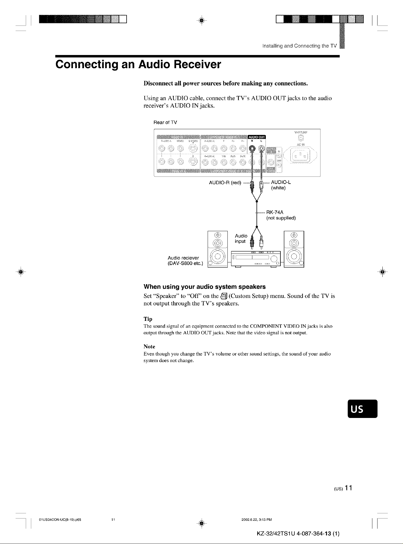
Connecting an Audio Receiver
Disconnect all power sources before making any connections.
Using an AUDIO cable, connect the TV's AUDIO OUT jacks to the audio
receiver' s AUDIO IN jacks.
Rear of TV
A;
i ii i _j
AUDIO-R (red) ---_ _---- AUDIO-L
÷
_ (white)
{,._-_ RK-74A
(not supplied)
Audio reciever
(DAY-S800 etc)
When using your audio system speakers
Set "Speaker" to "Off" on the _ (Custom Setup) menu. Sound of the TV is
not output through the TV's speakers.
Tip
The sound signal of an equipment connected to the COMPONENT VIDEO IN jacks is also
output through the AUDIO OUT jacks. Note that the video signal is not output.
Note
Even though you change the TV s volume o" other sound settings, the sound of your audio
system does not change.
,n0u,°°4
÷
I I 01US04CON-UC(8+t 9} p65
{us)11
1t
÷
2002622, 3:13 PM
II
KZ-32/42TS 1U 4-087-364-13 (1)
II
_ Installing and Connecting the TV
4, II
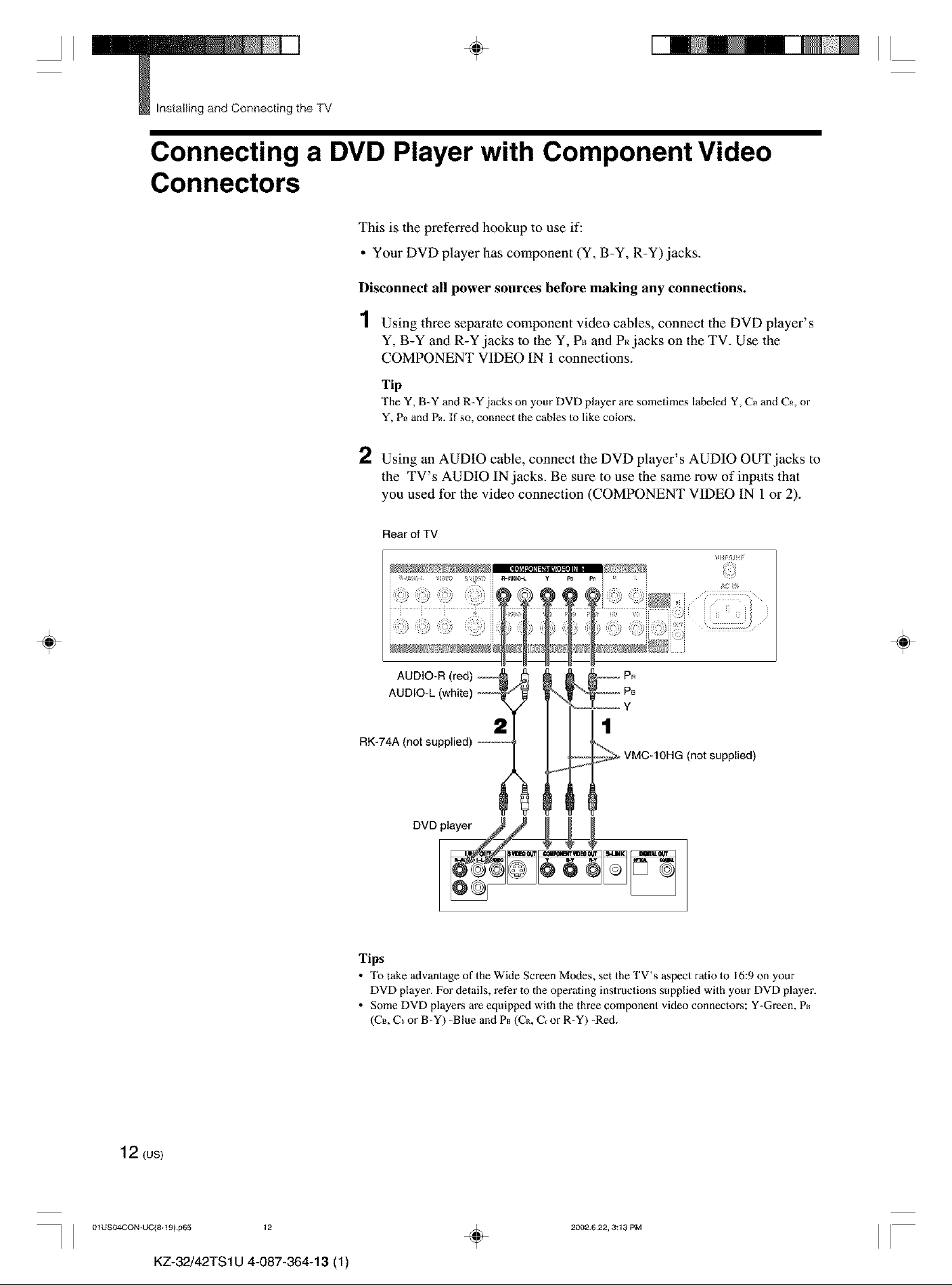
Connecting a DVD Player with Component Video
Connectors
This is the preferred hookup to use if:
• Your DVD player has component (Y, B-Y, R-Y) jacks.
Disconnect all power sources before making any connections.
1 Using three separate component video cables, connect the DVD player's
Y, B-Y and R-Y jacks to the Y, P_ and P_ jacks on the TV. Use the
COMPONENT VIDEO IN 1 connections.
Tip
The Y, B-Y and R-Y jacks on your DVD player are sometimes labeled Y, C_ and C_, or
Y, P_ and PR. If so, connect the cables to like colors.
÷
2 Using an AUDIO cable, connect the DVD player's AUDIO OUT jacks to
the TV's AUDIO IN jacks. Be sure to use the same row of inputs that
you used for the video connection (COMPONENT VIDEO IN 1 or 2).
Rear of TV
V!'FtlJ_
PR
P8
Y
2
RK-74A (not supplied) ----_,
1
(not supplied)
÷
12 (us)
I I 01USO4CON_UC(8+t 9} p65 12
KZ-32/42TS1U 4-087-364-13 (1)
Tips
• Totake advantage of the Wide Screen Modes, set theTV's aspect raliolo 16:9onyour
DVD player. For details, refer Io the operaling inslructions supplied with your DVD player.
• Some DVD player,s are equipped with the three component video connectons; Y-Green, P_
(CB, Cbor B-Y) -Blue and P_ (C_, C_or R-Y) -Red.
2002.622, 3:13 PM
÷
II
II ÷ II
Installing and Connecting the TV
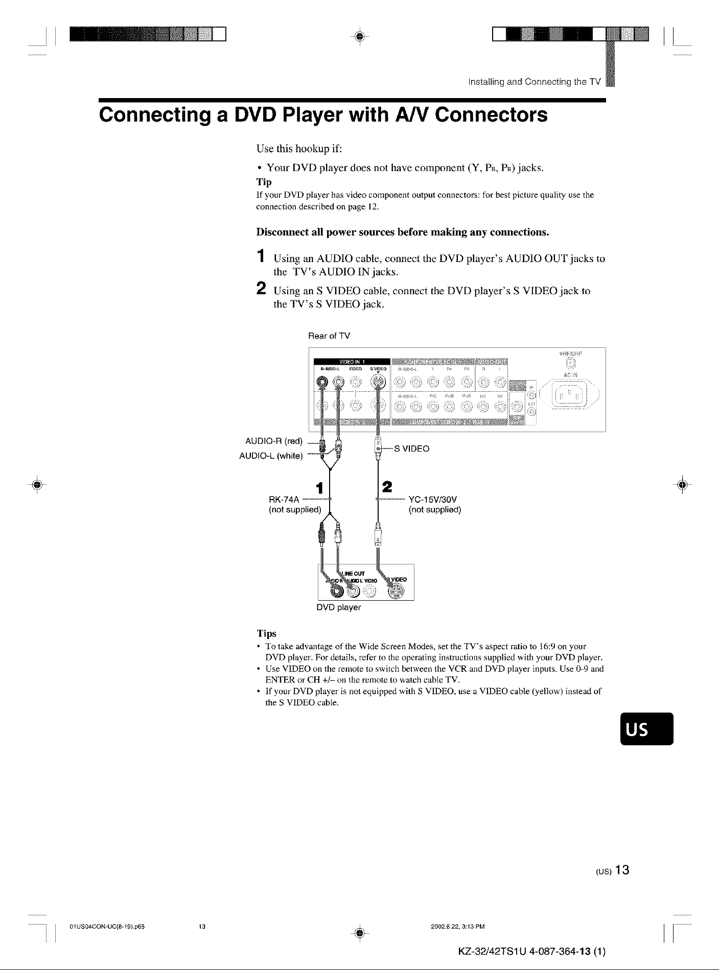
Connecting a DVD Player with A/V Connectors
Use this hookup if:
• Your DVD player does not have component (Y, P_, PR)jacks.
Tip
If your DVD player has video component oulput connectors: for best picture quality use the
connection described on page 12.
Disconnect all power sources before making any connections.
1 Using an AUDIO cable, connect the DVD player's AUDIO OUT jacks to
the TV's AUDIO IN jacks.
2 Using an S VIDEO cable, connect the DVD player's S VIDEO jack to
the TV's S VIDEO jack.
Rear ofTV
÷
AUDIO-L (white) _----
1
RK-74A ------
(not supplied)
DVD player
Tips
• To take advantage of the Wide Screen M(xtes, set the TV's aspect ralio 1o 16:9 on your
DVD player. For details, refer to the operating instructions supplied with your DVD player.
• Use VIDEO on the remote 1o switch between the VCR and DVD player inputs. Use 0-9 and
ENTER or CH +/- on the remote to watch cable TV.
• If your DVD player is not equipped with S VIDEO, use a VIDEO cable (yellow) inslead of
the S VIDEO cable.
_--S VIDEO
2
"--_ YC-15V/30V
(not supplied)
÷
I I 01US04CON-UC(8+t 9) p65
(us)13
13
÷
2002622, 3:13 PM
II
KZ-32/42TS 1U 4-087-364-13 (1)
II
_ Installing and Connecting the TV
÷ II
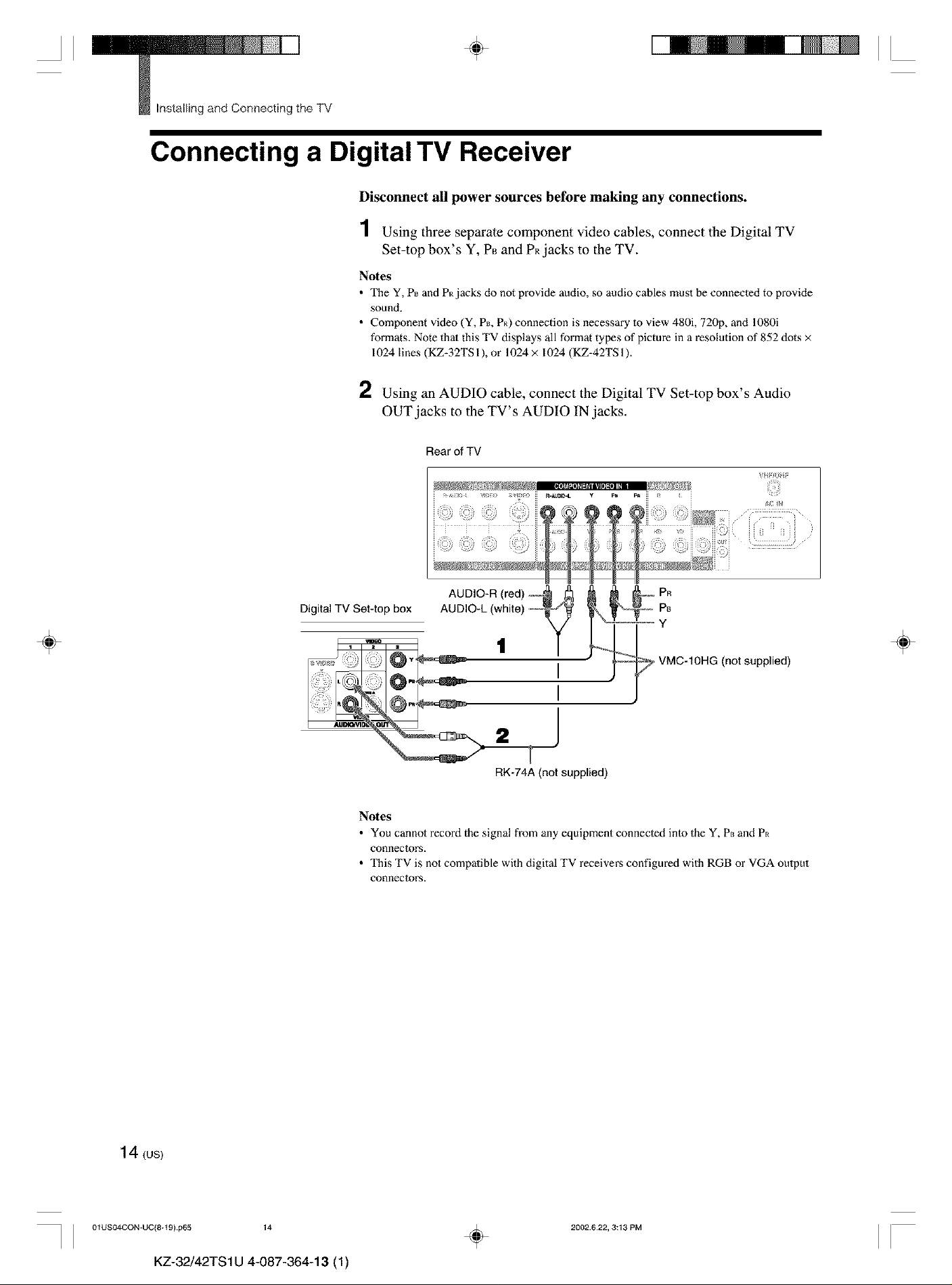
Connecting a Digital TV Receiver
Disconnect all power sources before making any connections.
1 Using three separate component video cables, connect the Digital TV
Set-top box's Y, P_ and PR.jacks to the TV.
Notes
• The Y, P_ and P_ jacks do not provide audio, so audio cables must be connecled to provide
sound.
• Component vMeo (Y, P_, P_) connection is necessary m view 480i, 720p, and 1080i
formats. Note thai this TV displays all format types of picture in a resolution of 852 dots ×
1024 lines (KZ-32TS 1), or 1024 × 1024 (KZ-42TS 1).
2 Using an AUDIO cable, connect the Digital TV Set-top box's Audio
OUT jacks to the TV's AUDIO IN jacks.
÷
Digital TV Set4op box
Notes
• You cannol record the signal from any equipment connecled inlo the Y, P_ and P_
conneclorN.
• This TV is not compalible with digital TV receivers configured with RGB or VGA oulput
conneclolN.
Rear of TV
PR
P8
Y
÷
VMC-10HG (not supplied)
RK-74A (not supplied)
14 (us)
I I 01USO4CON-UC(8+t 9} p65 14
KZ-32/42TS1U 4-087-364-13 (1)
÷
2002.622, 3:13 PM
II
II ÷ II
Installing and Connecting the TV
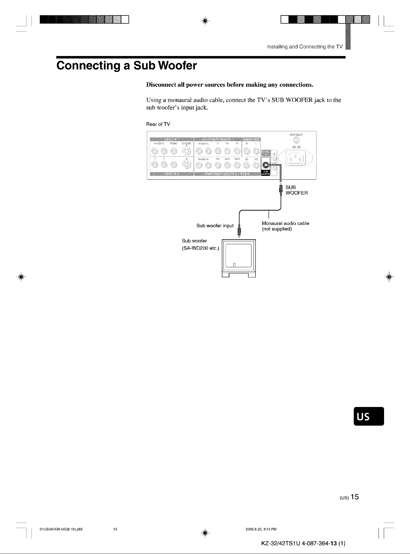
Connecting a Sub Woofer
Disconnect all power sources before making any connections.
Using a monaural audio cable, connect the TV's SUB WOOFER jack to the
sub woofer's input jack.
Rear of TV
÷
Sub woofer input
(SA-WD200 etc.)
Sub woofer
WOOFER
I SUB
r
0
Monaural audio cable
(not supplied)
÷
I I 01USO4CON-UC(8+t 9) p65
{us)15
15
÷
2002622, 3:13 PM
II
KZ-32/42TS 1U 4-087-364-13 (1)
II
_ Installing and Connecting the TV
4, II
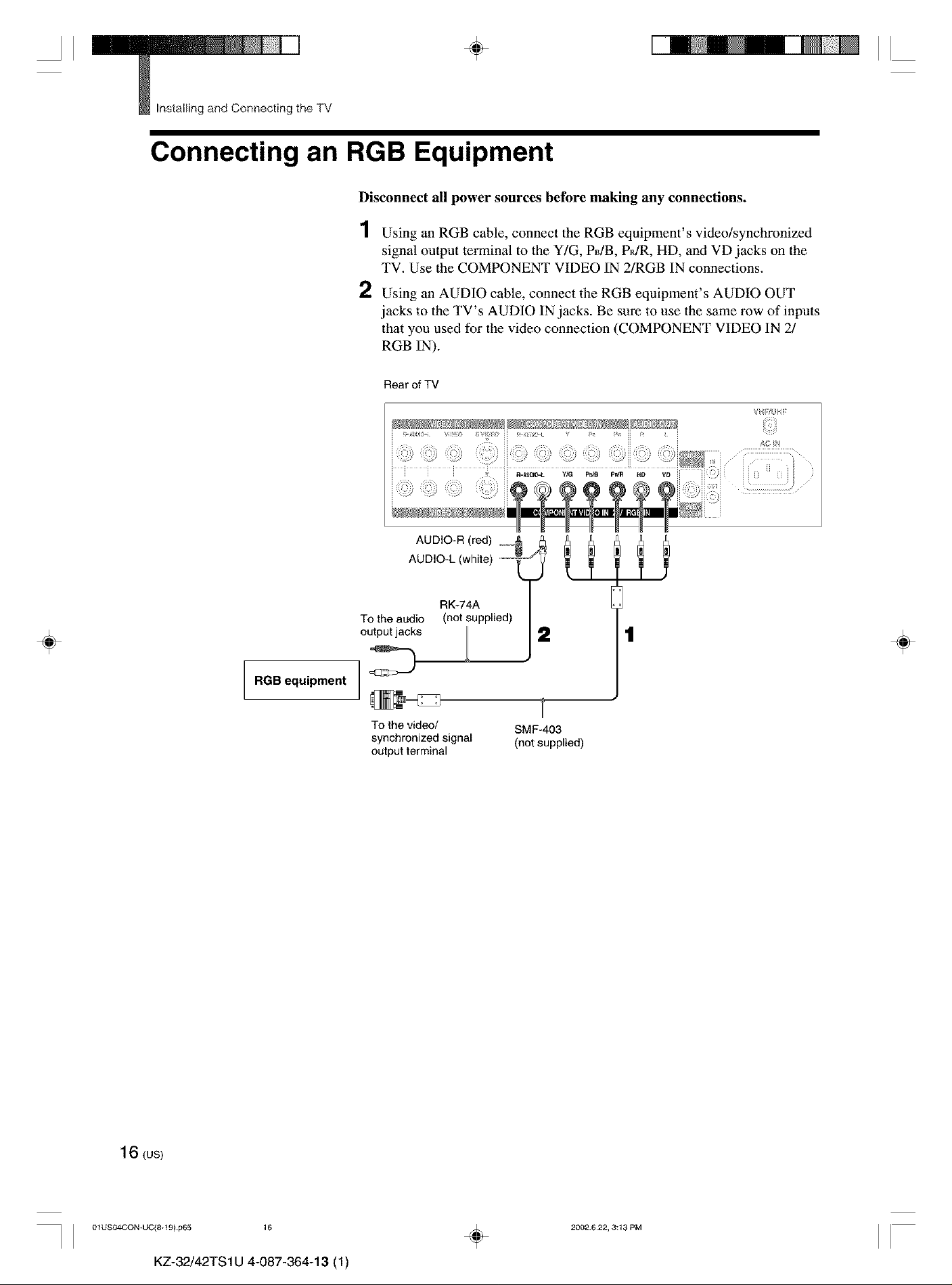
Connecting an RGB Equipment
Disconnect all power sources before making any connections.
1 Using an RGB cable, connect the RGB equipment's video/synchronized
signal output terminal to the Y/G, PdB, PR/R, HD, and VD jacks on the
TV. Use the COMPONENT VIDEO IN 2/RGB IN connections.
2 Using an AUDIO cable, connect the RGB equipment's AUDIO OUT
jacks to the TV's AUDIO IN jacks. Be sure to use the same row of inputs
that you used for the video connection (COMPONENT VIDEO IN 2/
RGB IN).
Rear of TV
÷
RGB equipment
To the audio
output jacks
To the video/
synchronized signal
output terminal
RK-74A
(not supplied)
2
SMF-403
(not supplied)
1
1
÷
16 (us)
I I 01US04CON-UC(8+t 9) p65 16
KZ-32/42TS1U 4-087-364-13 (1)
÷
2002.622, 3:13 PM
II
II ÷ II
Installing andConnecting the TV
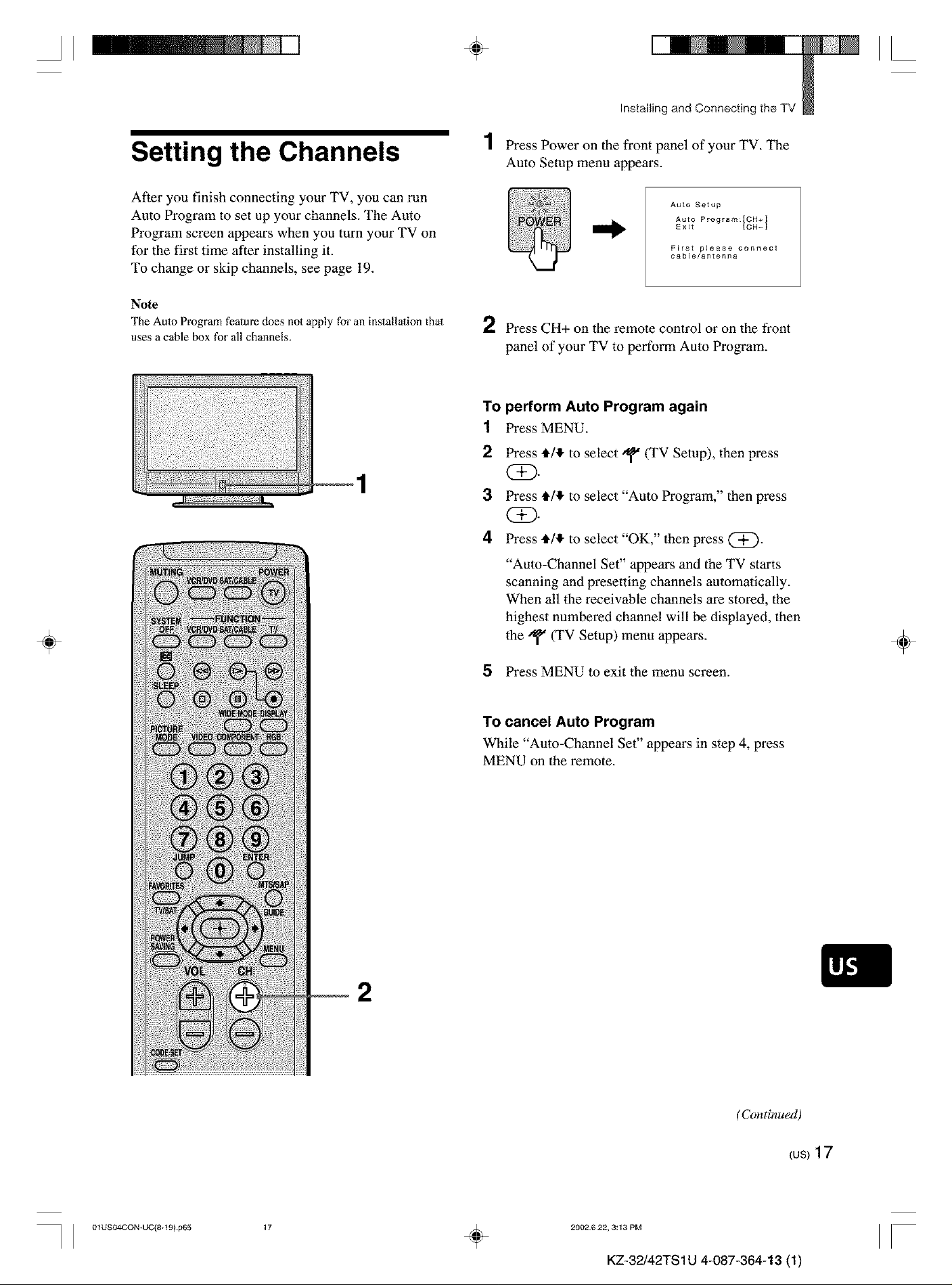
Setting the Channels
After you finish connecting your TV, you can run
Auto Program to set up your channels. The Auto
Program screen appears when you turn your TV on
for the first time after installing it.
To change or skip channels, see page 19.
Note
The Auto Program feature does not apply for an installation that
uses a cable box for all channels.
1 Press Power on the front panel of your TV. The
Auto Setup menu appears.
Auto Setup
Auto Program:[CH+]
Exit [CH-I
First please connect
cable/antenna
2 Press CH+ on the remote control or on the front
panel of your TV to perform Auto Program.
To perform Auto Program again
1 Press MENU.
2
Press l_/,l_ to select _" (TV Setup), then press
(Z).
3
Press l_/,l_ to select "Auto Program," then press
(i)-
4
Press l_/,l_ to select "OK," then press @.
÷
"Auto-Channel Set" appears and the TV starts
scanning and presetting channels automatically.
When all the receivable channels are stored, the
highest numbered channel will be displayed, then
the/_ (TV Setup) menu appears.
5 Press MENU to exit the menu screen.
To cancel Auto Program
While "Auto-Channel Set" appears in step 4, press
MENU on the remote.
÷
I I 01USO4CON-UC(8+t 9} p65
2
(Continued)
_us)17
17
÷
2002622, 3:13 PM
II
KZ-32/42TS 1U 4-087-364-13 (1)
II
_ Installing and Connecting the TV
÷
II
To watch CATV channels
You have to subscribe to a cable TV company. Note
that cable TV cannot be received in some areas. This
TV receives 1-125 cable TV channels. For details on
cable TV subscription, consult your nearest cable TV
company.
1 Press MENU.
2 Press _/_ to select'q'(TVSetup), then press
(SD
3 Press_/lto select"Cable," then press(Z).
4 Press_/lto select"On," then press (i)-
5 Perform steps 3and 4 on page 17.
Note
You cannot receive and set the CATV channels and UHF
channels at the same time.
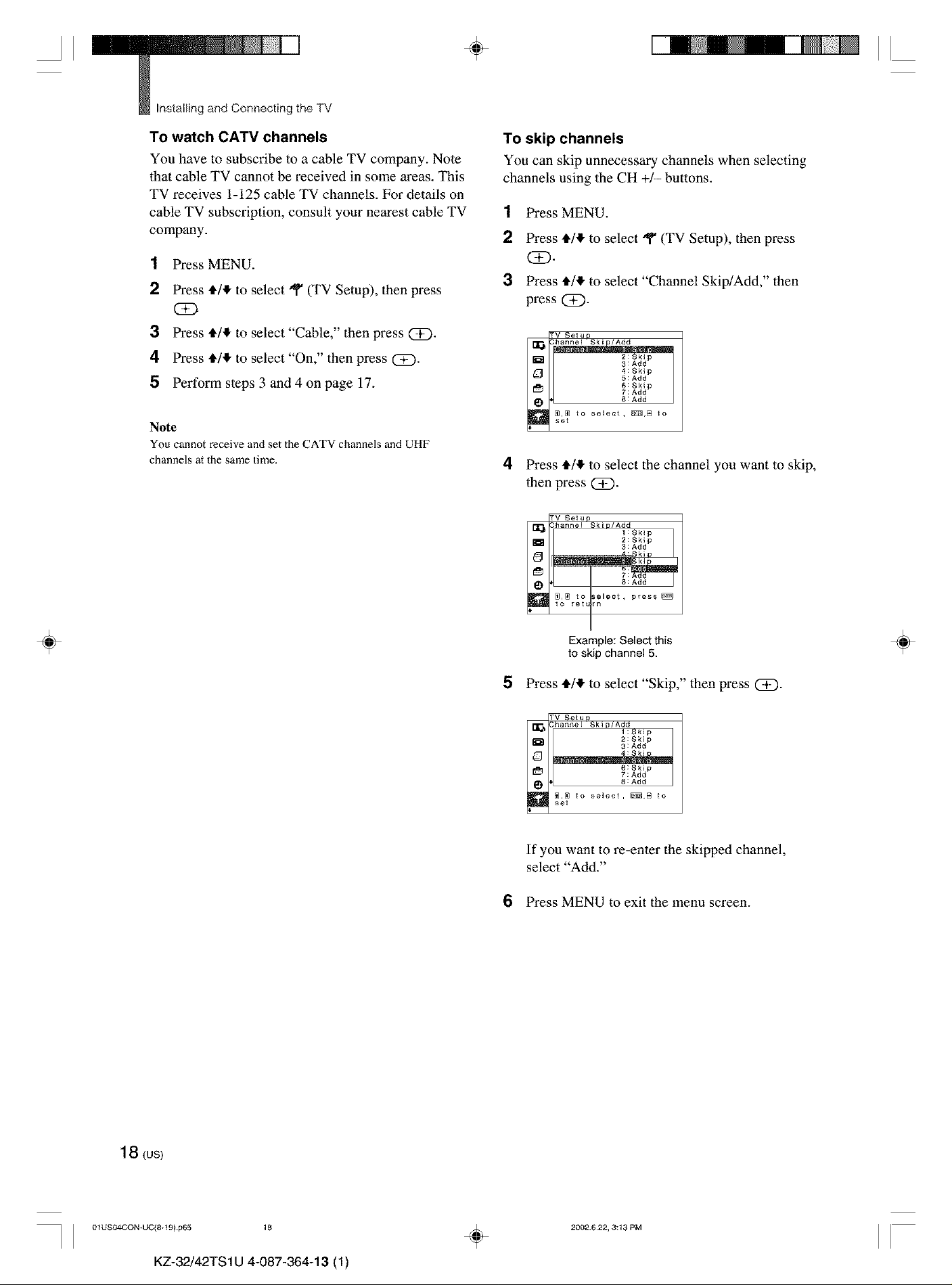
To skip channels
You can skip unnecessary channels when selecting
channels using the CH +/- buttons.
1 Press MENU.
2 Press */_ to select "q" (TV Setup), then press
(SE).
3 Press */_ to select "Channel Skip/Add," then
press(Z).
TV _!up
D 3: Add
[_H 7:Add
L_ 8 : Add
!111_ _ to select, _,B to
6:Skip
4 Press */_ to select the channel you want to skip,
then press QD.
TV 8#!_p
_lChannel Skiu/Add
m 2:Skip
1:Skip
3:Add
÷
_,_ to _elect, press_
to retLrn
Example: Select this
to skip channel 5.
5 Press _/_ to select"Skip,"then press Q_).
TV Be!up
_ _hanne[ Ski P/Ald_tSki p
_'__ 3: Add
L_]_ 8 : Add
_N;_ to select, _,B to
If you want to re-enter the skipped channel,
select "Add."
2:Skip
6:Skip
6 Press MENU to exit the menu screen.
÷
18 (us)
J J 01USO4CON-UC(8+t 9) p65 18
KZ-32/42TS1U 4-087-364-13 (1)
÷
2002.622, 3:13 PM
II
 Loading...