

Sony KZ-32TS1U, KZ-41TS1U, KF-60DX100 Service Manual
Training Manual
Plasma TV &
Grand Wega Projection TV
Models: KZ-32TS1U
KZ-41TS1U
KF-60DX100
KZ-32TS1U
Diagnostic Guides
Course: TVP-13
KF-60DX100

Table of Contents
KZ-32TS1U // KZ-42TS1U
Introduction ...........................................1
1. Normal Operation .............................2
2. Self-Diagnostics................................3
3. Board Selection by Defect...............4
4. Plasma Panel Picture Defects .........5
5. Board Location..................................6
6. Service Mode.....................................7
7. Adjustments when the
B Board is Replaced............................12
8. Plasma Panel Replacement -
KZ-32TS1U ............................................15
9. Plasma Panel Replacement -
KZ-42TS1U ............................................23
10. Standby Power / Power ON..........28
Power ON .............................................................. 28
11. Fan Drive Circuit ............................30
12. Video Signal Flow ..........................32
13. What is Flat Screen
Plasma Technology? ...........................35
Theory of Operation ............................................ 35
KF-60DX100
Introduction ..........................................37
15. Normal Operation ..........................38
16. Self-Diagnostics.............................39
17. Board Selection by Defect............40
18. Board Locations.............................41
19. Adjustments ....................................42
20. Service Mode..................................44
21. Determining if the
Optical Unit is OK ................................45
22. Optical Unit Removal ....................46
23. Screen / Mirror Replacement.......50
24. Troubleshooting -
TV Shutdown ........................................53
25. Power Supply .................................54
26. Fan Control - KF-60DX100............56
27. Grand Wega Lamp Control...........59
Lamp Operation ................................................... 59
Lamp ON Display ................................................. 62
Power Block Location & Removal..................... 62
Troubleshooting.................................................... 63
28. Video Process ................................65
Sony Model KZ-32TS1U // KZ-41TS1U TV Diagnostic Guide
Sony Plasma TV KZ-32TS1U/KZ-41TS1U Introduction
This training manual has been organized to provide a quick diagnosis of problems in Sony Plasma screen TV
models KZ-32TS1U and KZ-41TS1U. The circuitry in these two TV sets is similar, but the boards and plasma
panels are mounted differently.
Because the Plasma TV set is a new design concept, Chapter 1 will cover normal Plasma TV operation. The last
chapter will cover plasma principles / concepts (only necessary for background information).
Repairs to these TV models involve identifying and replacing a circuit board, the plasma panel or other parts
such as the fan or the on/off switch. This manual is divided into thirteen chapters:
Table of Contents
Chapter Contents
1. Normal Operation This 16x9 plasma screen TV operates differently from a picture
tube TV.
2. Self Diagnostics The front panel Standby light blinks to indicate major and minor
problems.
3. Board Selection by Defect Listing of possible defects and where they may be.
4. Plasma Panel picture
Defects
5. Board Location Location of replaceable boards in model KZ-32TS1U.
6. Service Mode Service Mode access and contents.
7. Adjustments Adjustments after the B board is replaced.
8. Plasma Panel
Replacement KZ32TS1U
9. Plasma Panel
Replacement KZ42TS1U
10. Standby power / Power
ON circuit description
11. Fan Drive circuit
description
12. Video Flow circuit
description
13. Plasma Display
Technology
Listing of possible plasma panel screen defects
Pictured procedure to avoid problems in access and reassembly.
KZ32TS1U and KZ42TS1U have separate pictured procedures.
Pictured procedure to avoid problems in access and reassembly.
KZ32TS1U and KZ42TS1U have separate pictured procedures.
Location and circuit operation for Standby voltage and Power ON
sequence.
Fan Operation, troubleshooting, and testing.
Signal levels, description and symptoms when missing.
Plasma Cell Operating Concepts
1
Sony Model KZ-32TS1U // KZ-41TS1U TV Diagnostic Guide
Chapter 1 - Normal Operation
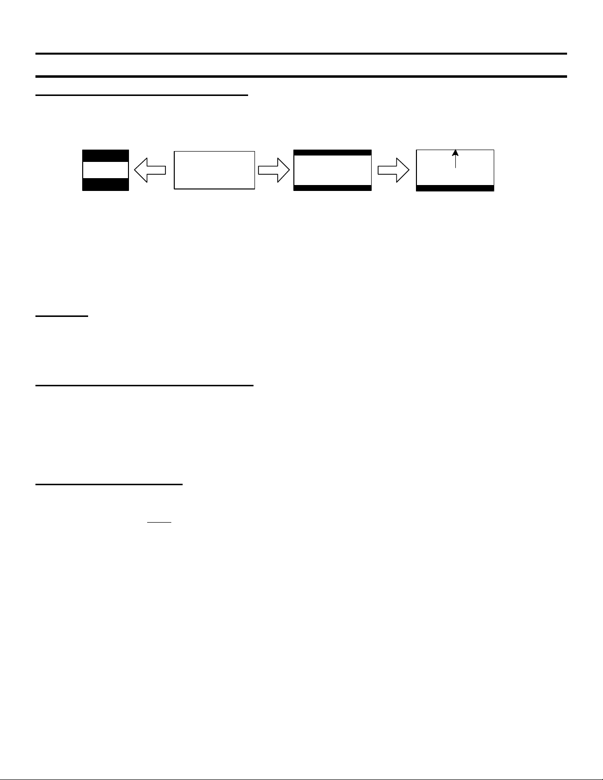
Black top and bottom (letterbox) borders – Even though this TV has a wide 16x9 screen, it is still possible to
receive a picture with top and bottom black bands. Movies are shot in many aspect ratios. The most common
ratios are 4:3, 1.85:1 and 2.35:1. The picture displayed is dependent upon what aspect ratio the movie was shot
in and how different it is from your TV screen’s aspect ratio. Ref Figure 1-1 below:
2:35:1 Movie
4x3 TV
Figure 1-1 - Display of a 2:35:1 Aspect Ratio Movie
The 1.85:1 aspect ratio movie will display without the black bands on this 16x9 screen TV (16/9 = 1.77:1 aspect
ratio) because their 1.85 and 1.77 aspect ratios are almost the same. The extra wide 2.35:1 aspect ratio movie
camera is still used in the film industry (mostly overseas). It produces the black borders even on a 16x9 (1.77:1)
TV screen. In this TV, you may choose the “Subtitle” screen mode from the menu to fill the top of the screen,
leaving only a black band at the bottom for the subtitle.
Fan Noise – Once the TV is turned on, the fan starts. The fan itself makes no noise but air flowing through the
TV does, especially when the TV is enclosed. This low level of air turbulence is normal. The Main CPU monitors
the fan run voltage, rotation and ambient temperature of the power supply. This information is available to the
user from the User Status menu as an OSD (on screen display OK or NG indication). Details such as the
temperature are in the Service Mode (see Section 6).
Video Inversion to prevent border burn in – After a (undetermined) period of use, some plasma cells will not
be as bright as others, causing an incorrect tint (because one of the red, green or blue plasma cells will darken,
leaving the others bright). Burn in can be prevented from the user menu. From the Screen Saver menu,
“Picture Inversion” may be selected to “clean” the screen (black becomes white and white becomes black
momentarily), restoring normal brightness to the cells.
If this Inversion function were set for AUTOmatic, picture inversion would occur at a specified time every day if
the TV were ON. This picture inversion may alarm a viewer that is not aware that this is normal for this TV.
Picture Shift / Picture Orbit – To reduce the possibility of a stationary image permanently “burnt” into the
plasma screen phosphor, the picture can be set to automatically move in a circular “orbit” pattern. The menu’s
“picture orbit” can be set to small, medium or large orbit range and its cycle time can be 10, 30, 60 seconds or 5
minutes. Picture Orbit must be turned ON (normally OFF) if the user usually watches constant pattern images
such as movies with borders, stock market scenes, etc.
16x9 TV
Subtitle Mode
2
Sony Model KZ-32TS1U // KZ-41TS1U TV Diagnostic Guide
Figure 2-1
Chapter 2 - Self-Diagnostics
Standby/Sleep Light
The front panel Standby LED blinks to indicate a fault. Refer to Figure 2-1. If the TV does not start up, the
LED continually blinks to indicate a problem.
Standby/sleep
light
TV
If the TV starts and shuts down, the LED will repeatedly blink to indicate the reason for shutdown or A/V muting.
Table 2-1 shows the boards that can cause the Standby LED to blink continuously and Table 2-2 shows the
boards that cause shutdown.
Table 2–1 - Causes of Continuously Blinking LED – No TV A/V (black screen)
Cause Suspect Board
EEPROM ID check error B board
EEPROM read /write error B board
Color Decoder IC error B board
Panel will not initialize (start) Plasma panel
Low B+ at start up Plasma panel, power supply board
Table 2-2 - Cause of Standby LED Blinking in a Pattern - TV Shutdown
Times Standby
LED blinks
2 times Plasma panel error Plasma panel
Cause Suspected board
3 times Internal TV temperature at critical Q board, Fan, or possibly B board
4 times Digital 5Vdc output voltage excessive or
too low.
5 times Digital 3.3Vdc output voltage excessive or
too low.
6 times Analog 6Vdc output voltage excessive or
too low.
Power Supply Output CN1/pin 9 / 10
B board is the load - CN101.
Power Supply Output CN1/pin 5 / 6
B board is the load - CN101.
Power Supply Output CN1/pin 13 / 14
B board is the load - CN101.
3
3. Board Selection by Defect
Chapter 3 - Board Selection by Defect
Table 3-1 shows the boards that could cause the symptoms listed. The most likely board is designated #1,
second likely #2, etc. Two #1 means both boards have an equal probability. To resolve the conflict, testing is
performed in the Standby/Power ON, Fan Drive, Video Flow circuit descriptions (Chapters 10-12) or the Plasma
Panel picture defects (Chapter 4).
For isolation purposes, the TU (tuner board) may be unplugged and the TV will work, displaying video inputs.
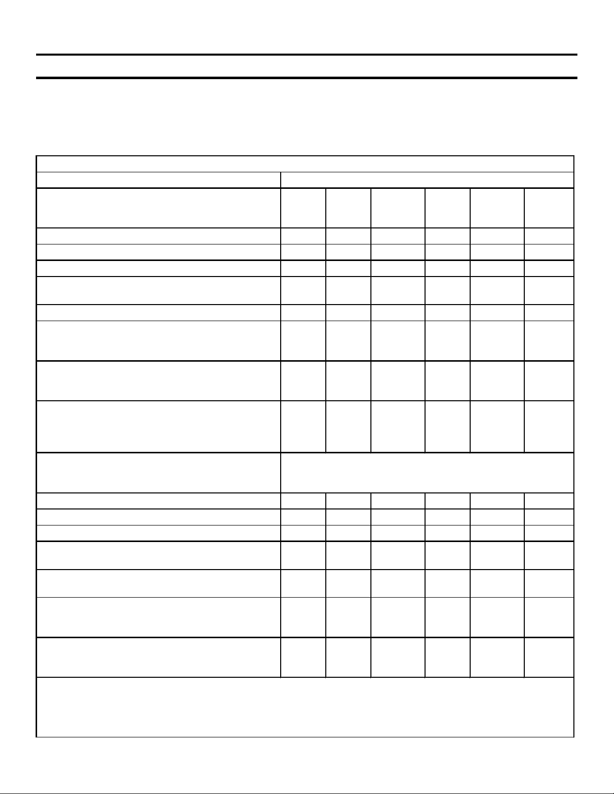
Table 3-1 - Plasma TV model KZ-32TS1U / KZ42TS1U Board Selection by Defect
Probable Circuit Board Failure
Symptom B* H1 Power
Supply**
Audio Problem – all inputs 2 1
Audio Problem – TV channels (deselect SAP)
Dark Screen – sound OK 1 2 1
Dark Picture – sound OK (deselect Power Save
on the remote)
Dead Set - No relay click at plug in 2 1 3
Dead Set – Stby light OFF. No response to
front panel pwr button. Plug-in relay click
heard.
Dead Set – Except for Stby light ON. No
response to pwr button. Plug-in relay click
heard.
Fan not cooling (front panel Standby indicator
blinking.) See the TV menu and Fan block
diagram in Section 7. Fan NG = No voltage to
fan. Temp NG = Fan not working.
Noise Bars across the screen (horizontal) The rear metal shield must contact the conductive mesh
Standby Indicator blinking 2 times
Standby Indicator blinking 3 times
Standby Indicator blinking 4, 5 or 6 times
Video Distortion – With composite and S video
input only.
Video Distortion – With component (Y, R-Y, B-
Y) input only.
Video Distortion – With both composite and
component inputs. Try using the menu’s
“picture inversion” to “clean” the screen first.
Symptom B * H1 Power
*After B board replacement, adjustments for brightness and color balance are necessary. See Adjustments.
**The entire power supply board is listed in the service manual as “Switching Regulator”. The 32” and 42”
TV sets do not use the same Switching Regulator power supply and therefore have different part numbers.
***See Possible Plasma Panel defects for illustrations.
2 1
1 1
3 2 1 4
2 1 3
3 2 1
on all four sides and be screwed to the center TV board
assembly.
2 1
3 (2 = fan)
2 1
2 1
2 1
1 2 3
Supply
Q TU Plasma
Panel
***
1
Q TU Plasma
Panel
**
4
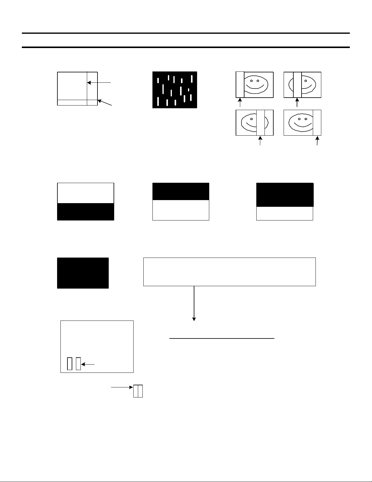
Chapter 4 - Plasma Panel Picture Defects
Board Location – Ref. Figure 4-1
V
a)
H
Vertical or
Horizontal
black / white
line through
the picture.
b)
Sony Model KZ-32TS1U // KZ-41TS1U TV Diagnostic Guide
c)
Colored rain
in a black
background.
White Noise
replaces 1/4
of the picture
d) e) f)
g)
Normal Pix
Black lower
half
Power Supply Board
CN 23
1
13, 15
gray wires
Normal Pix
Black upper
half
g) A Dark Screen with sound can be caused by the plasma
panel or the TV circuitry. Measure the DC voltages and signal
entering the plasma panel to determine which is defective.
Dark screen?
Check DC and signal video levels at CN23 & CN 1.
Normal Voltages with TV ON, any input
CN23/pin 1 = 55Vdc
CN23/pin 3 = 5Vdc
CN23/pin 8-10 = 78Vdc (32") or 82Vdc (42")
CN1/pins 13 & 15 (gray wires) = 1Vp-p @ 30MHz
If these input voltages/signals are OK, the plasma
panel is suspect. CN1 is on the plasma panel below
CN 1
1
the Power Supply board.
White noise
Black top, bottom
just white noise
5
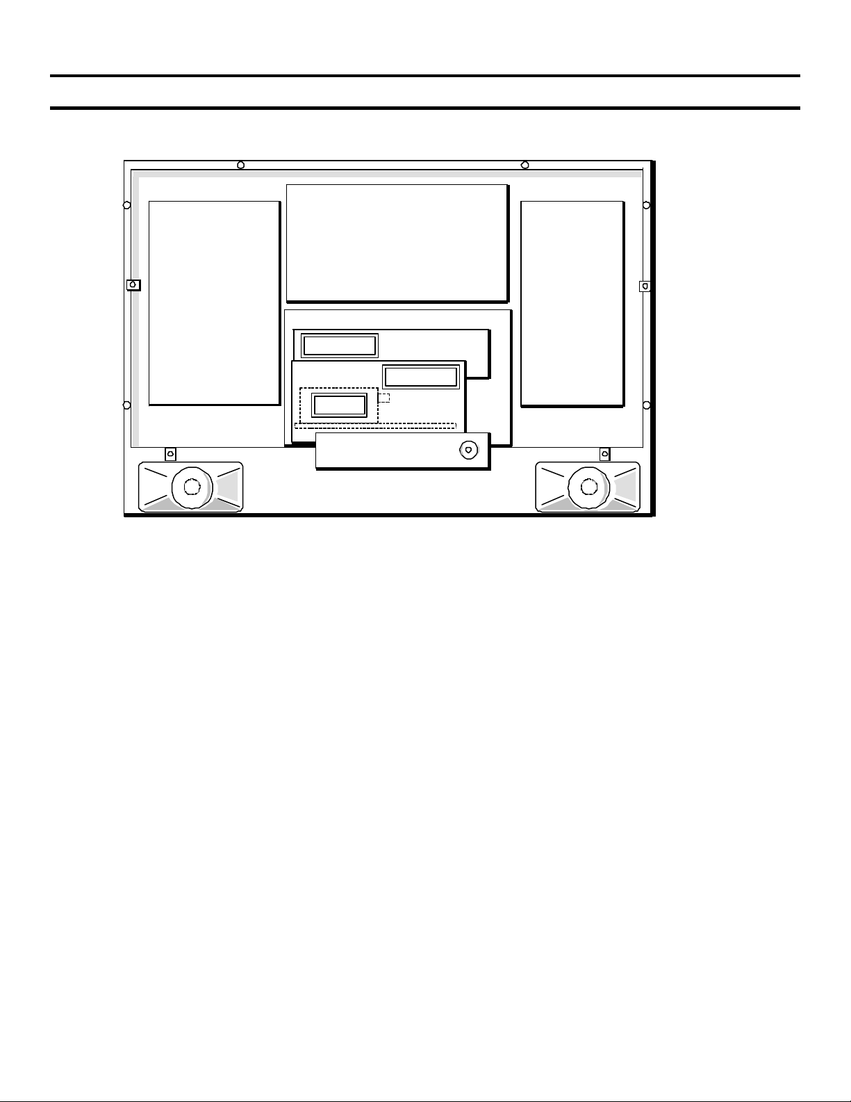
PLASMA
BOARD Y
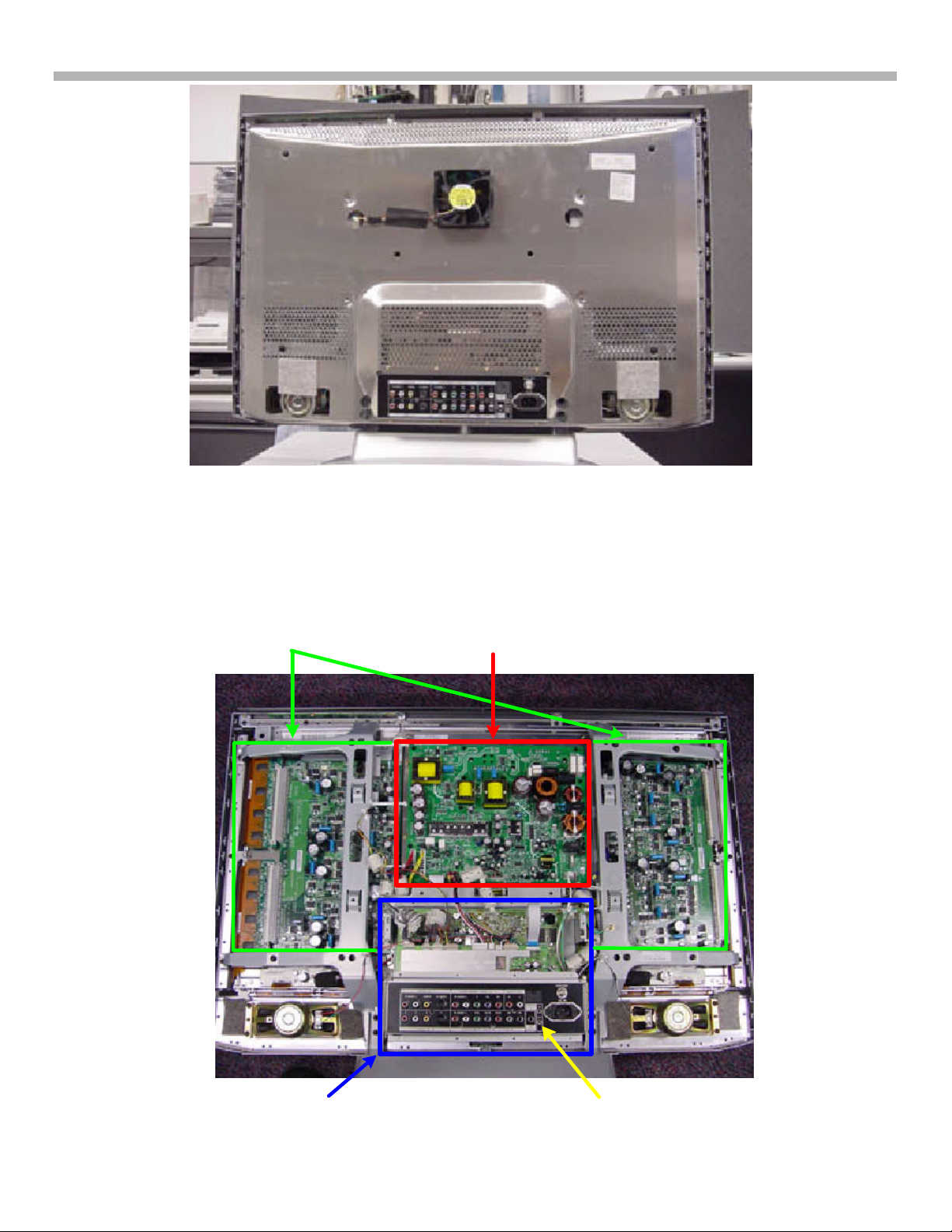
5. Board Location
Chapter 5 - Board Location
POWER
SUPPLY
BOARD
PLASMA
BOARD X
B BOARD
Q BOARD
TU BD.
VHF
IN
FIGURE 5-1 - BOARD LOCATION - KZ-32TS1U
8TVP13 1444 4/10/02
6
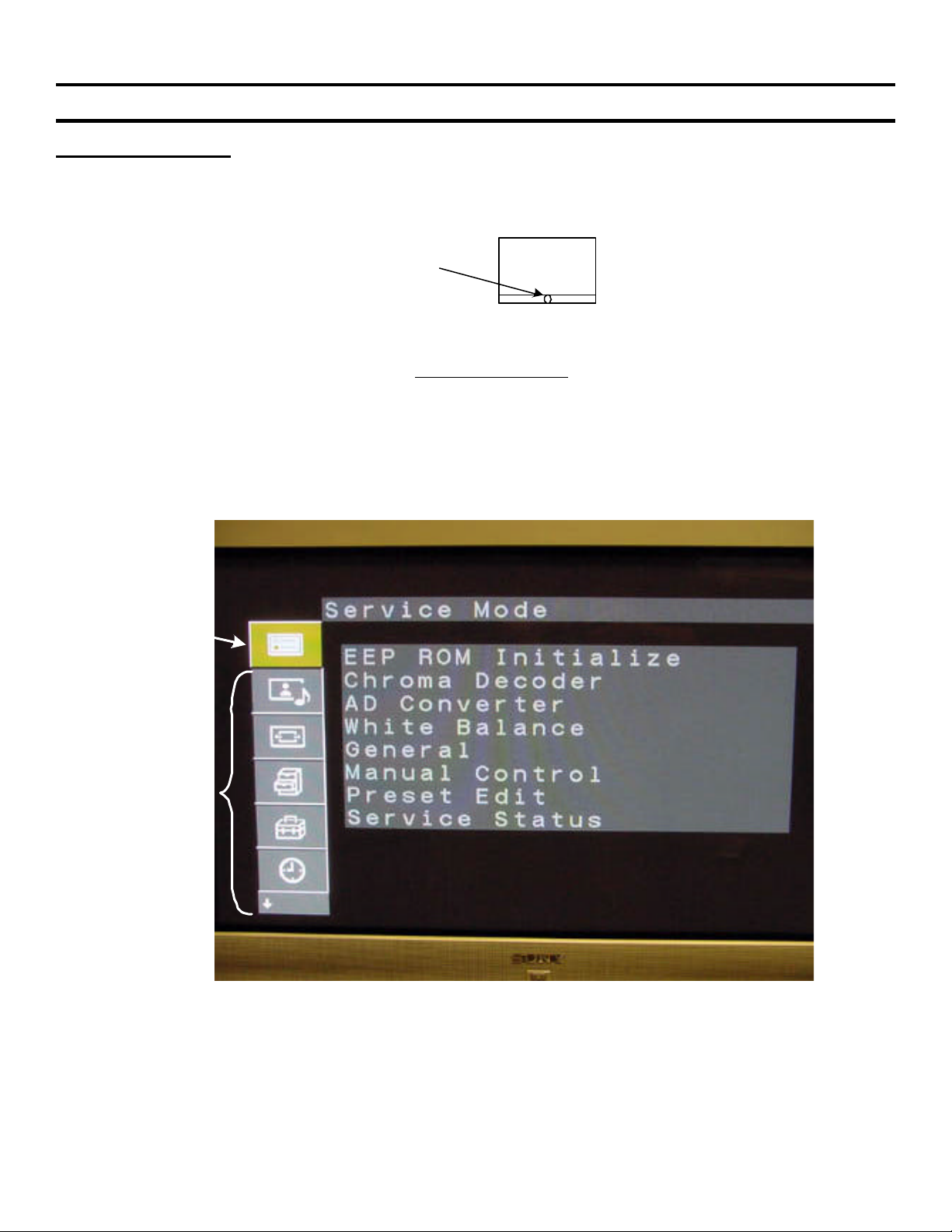
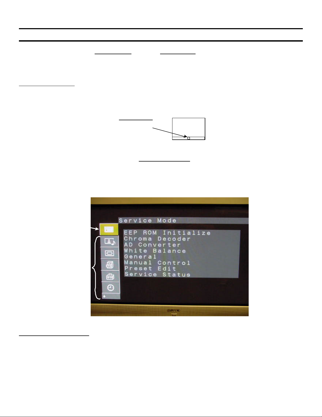
6. Service Mode
Figure 6-1
Chapter 6 - Service Mode
Service Mode Access
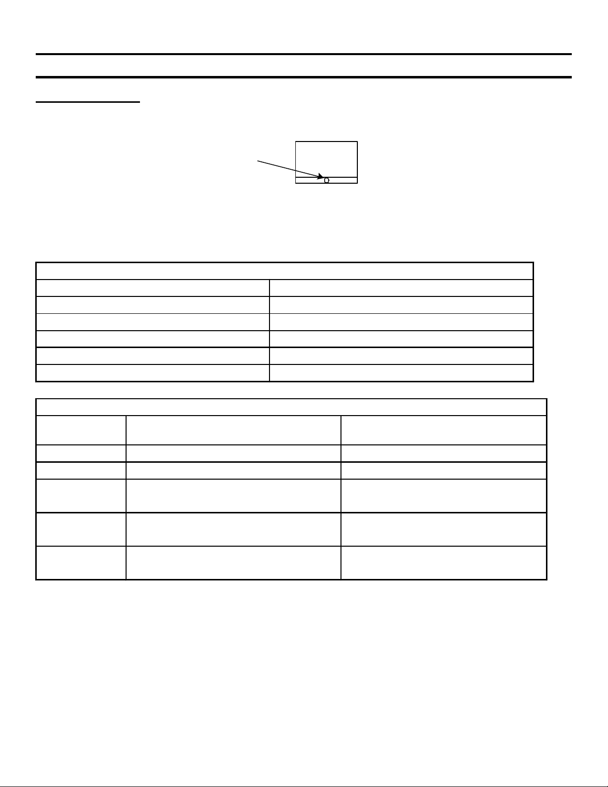
1. The TV must be in the Standby Mode as indicated by the front panel red light. Refer to Figure 6-1 for the
location of the standby light. If this Standby light is OFF, plug the TV into AC, press the front panel Power
button and then shut off the TV from the remote control. The Standby light should now be lit (red) while the
TV is OFF.
Standby/sleep
light
2. Using a Sony remote control aimed at the TV in the standby mode, quickly press: Display, 5, Volume +, Power
ON and MENU. If the TV turned ON when 5 was pressed, you did not press the next Volume + button fast
enough and will have to try again.
3. The following new service Mode menu shown in Figure 6-2 will appear above the user menu. Use the remote
control joystick to move and change the data as before. Store data as in previous service modes, by pressing
“Mute” and then “Enter”.
TV
Service
Menu
Normal
User
Menu
Figure 6-2 - Service Mode Display
7
6. Service Mode
ial number, elapse operation time and diagnostic are erased.
= 8.
Service Mode Contents
Table 6-1 - Service Mode Contents
Service Category Contents
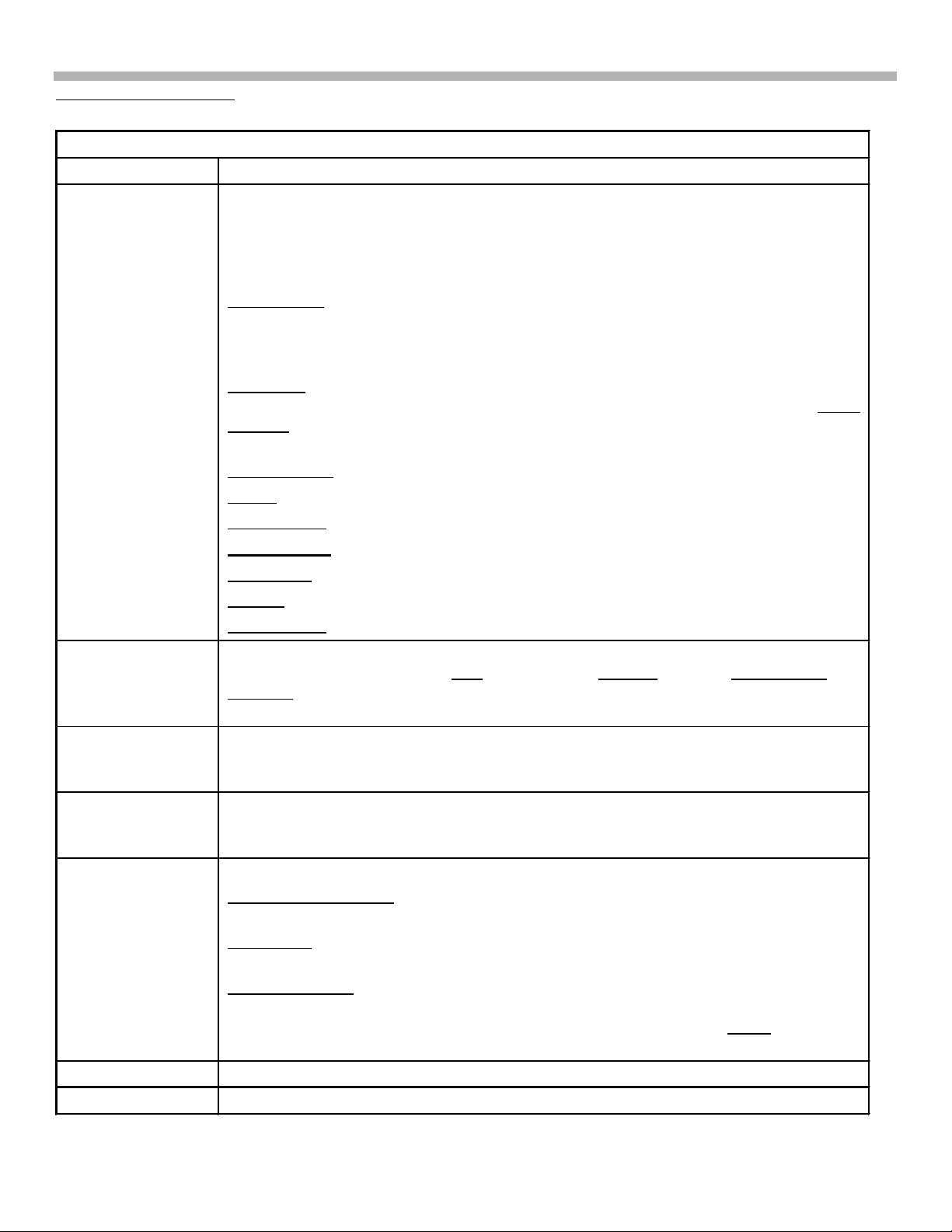
EEP ROM Initialize See Figure 6-3 for a list of Initialize contents. Selecting a line (like “Common”)
reveals two options: OK or cancel. Selecting OK stores default data and causes
the TV to reboot. You must press Menu when the TV turns back ON to return to
the service mode. Do not select OK unless you have read what you are resetting
to default levels.
Whole Area - Resets the entire EPROM and requires a full TV alignment
afterwards. The ser
This is used when the TV is made. For service, you can individually reset EPROM
contents:
Common - Resets items that are not signal related, such as: language, Orbit,
Diagnostic errors, serial number, color system and TV ON elapsed time. White
Balance – Resets Low, Mid and High Temperatures to midgain in preparation for
alignment after B board replacement.
Prog. Gamma - Is not used.
Tuner - Resets channels back to 2-13 and clears the Favorite channels.
Prog. Preset - Erases user station names.
Last Memory - Resets user video and audio preface settings.
User Mem – Is not used
Factory – Resets user settings to default except diagnostics and serial number.
Tuner Micom- Same as Tuner.
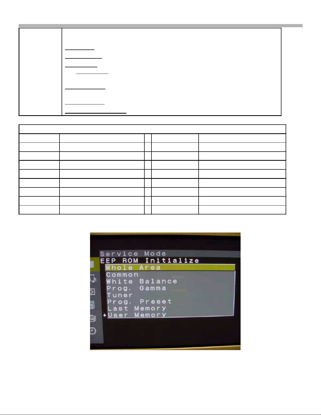
Chroma Decoder See Figure 6-4 for a content list. Preset contrast, sharpness, color and output levels
as shown in Figure 6-4. The Hue for NTSC = 8, Y Delay = 8, and Cb/Cr Offset
Sharp fo is the frequency the sharpness peaks. 0=2.5M, 1=3.2M, 2=4M, 3=off. Set
to 3.
AD Converter Adjust the brightness and hue for each input (video, component and RGB). Preset
these levels after the B board is replaced and touch up. See adjustments for the
procedure.
White Balance White balance adjustments at low, middle and high brightness levels. Preset these
levels after the B board is replaced and touch up. See adjustments for the
procedure.
General See Figure 6-5 for a content list.
AGC Wide & Narrow - Data affects capturing stations during auto programming
(wide = 14) and operation (Narrow = 13).
Fan Status - Displays the temperature of the power supply and the voltage applied
to the fan motor (8.6Vdc = slow).
Vs / Va Setting - The main plasma panel voltages Vs and Va are set using Uvrs
and Uvra. The 32” TV uses Uvrs = 82 and Uvra = 106. The 42” TV uses 93 and
128 respectively. Vs and Va needs adjustment if the logic board within the plasma
panel is replaced.
Manual Control See Figure 6-6 and 6-7. These are all preset to 00 except for: PDP =20.
Preset Edit See Figure 6-8. This section presets the parameters for a new video input signal.
8
6. Service Mode
Service Status See Figure 6-9. This section displays the status of the input signal, and TV
condition.
Signal/sync - Format, freq, and sync polarity of the input signal.
Power Supply – Low voltage output of the power supply in voltage DC.
Fan & Temp - The fan voltage and power supply temperature. Within this category
is a No Ack Dev - Points to an IC that is not communicating with the Main Micro
using a 4-digit defect code number. See No Acknowledge Device table 6-2.
Warning Status – Shows completion of communications from the Main Micro (B
board) to memory IC and to 15 others.
Operation Time – Elapse TV ON time.
Software & PLD version – Software in Main micro and Panel Micro.
Table 6–2 - Service Mode - Service Status under Fan and Temp, No Acknowledge Device
Defect Code Suspected IC Defect Code Suspected IC
0001 Audio Processor (A board) 0002 Audio Switch (Q board)
0004 AV Switch IC (U board) 0008 V Chip (Q board)
0010 3D Comb filter IC (B board) 0020 Color Decoder (B board)
0040 Plasma Panel (PDP) 0080 Tuner (TU board)
0100 Auto Wide IC (B board) 0200 A/D Converter (B board)
0400 EPROM (M board) 0800 System IC (B board)
1000 V Chip (Q board) 2000 PLD (B board)
4000 Real Time Clock IC (B board) 8000 Scan Converter (B board)
Figure 6-3 Service Mode - EEP ROM Initialize
9
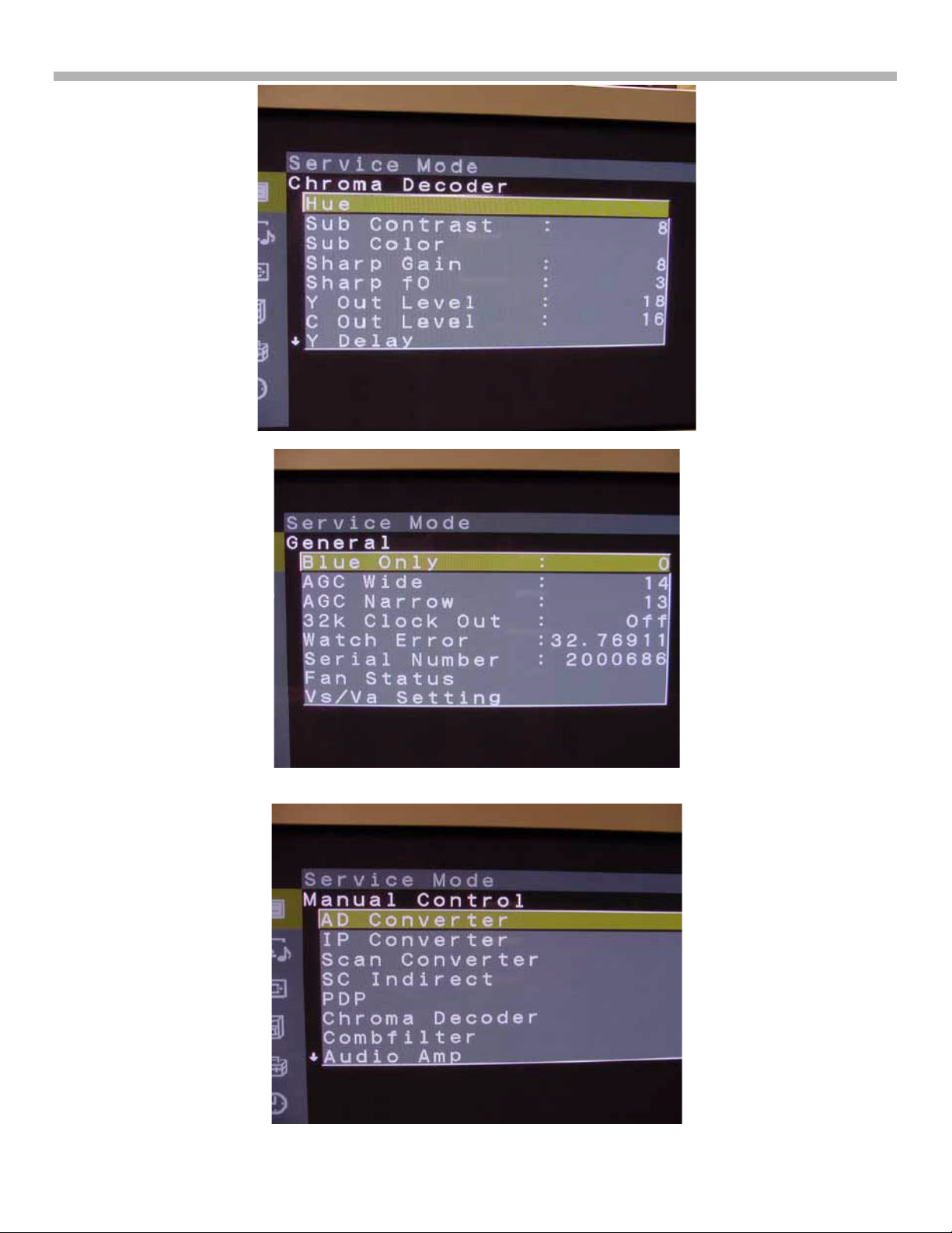
Figure 6-4 Service Mode – Chroma Decoder
6. Service Mode
Figure 6-5 Service Mode –General
Figure 6-6 Service Mode – Manual Control 1/2
10
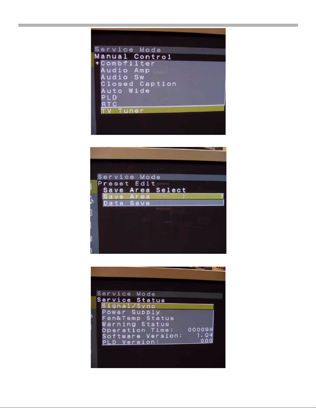
Figure 6-7 Service Mode – Manual Control 2/2
6. Service Mode
Figure 6-8 Service Mode –Preset Edit
Figure 6-9 Service Mode –Service Status
11
7. Adjustments when the B Board Needs to be Replaced
Chapter 7 - Adjustments when the B Board is Replaced
If the B board is replaced, the A/D Converter levels and white balance need to be adjusted or the brightness and
tint range will not be consistent when switching inputs. These settings are made from the service mode for each
input (Tuner, Video and Component) type and the data is saved in a NVM IC on the TV’s B board.
Service Mode Access
1. The TV must be in the Standby Mode as indicated by the front panel light. If this Standby light is OFF, plug
the TV into AC, press the front panel Power button and then shut off the TV from the remote control. The
Standby light should now be lit while the TV is OFF. Ref. Figure 7-1.
Standby Mode
Standby/sleep
light must be
red
Figure 7-1
TV
2. Using a Sony remote control aimed at the TV in the standby mode, press: Display, 5, Volume +, Power ON and
MENU, quickly. If the TV turned ON when 5 was pressed, you did not press the next Volume + button fast
enough and will have to try again.
3. The following new service Mode menu shown in figure 7-2 will appear above the normal user menu. Use the
remote control joystick to move and change the data as before. Store the new data by pressing Mute, and then
Enter, as before.
Service
Menu
Normal
User
Menu
Figure 7-2 - Service Mode Display
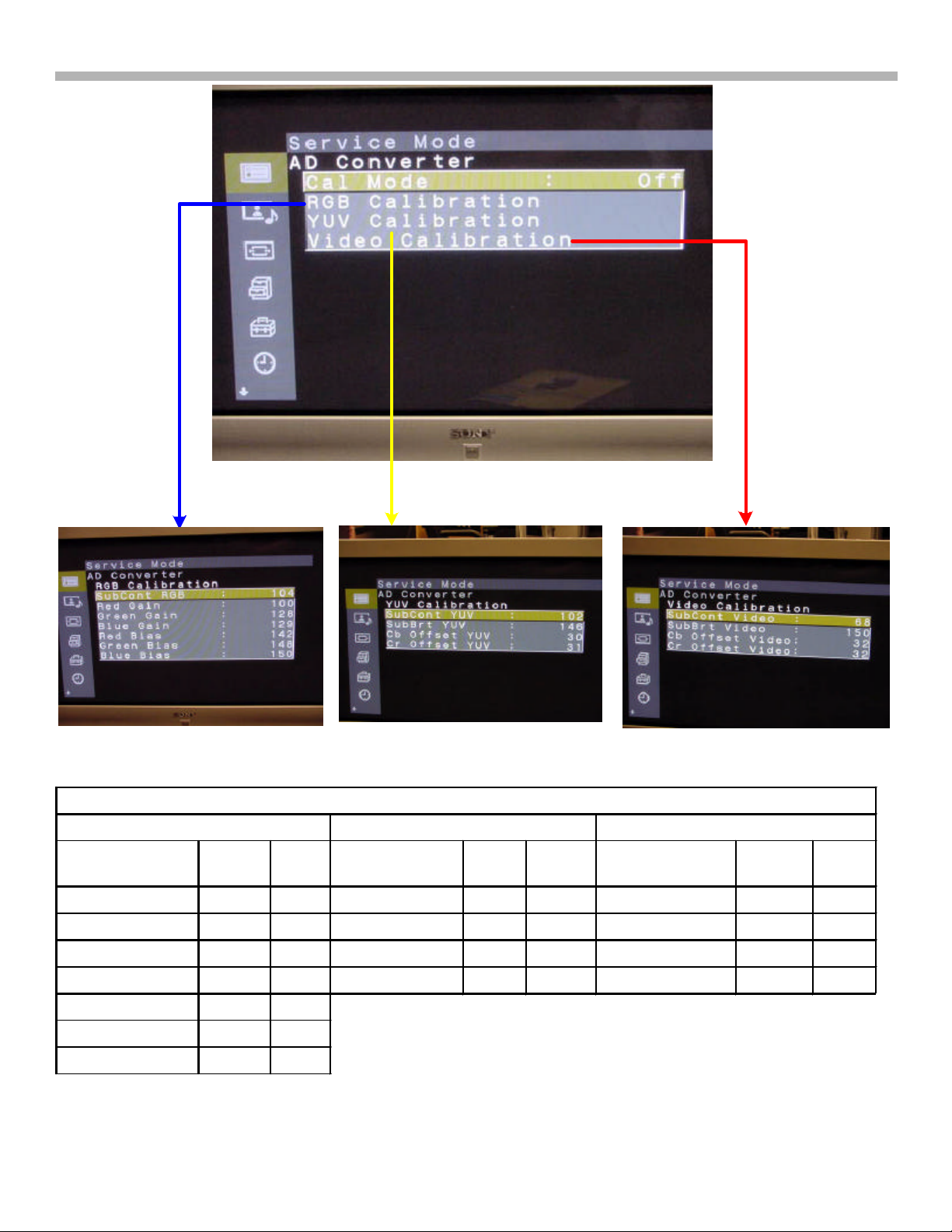
A/D Converter Adjustments
White balance and brightness levels for the three types of video inputs are set in the AD Converter area of the
service mode. All three types of video inputs (RGB, YUV and Video) are shown in Figure 7-3 and Table 7-1.
Adjust each one by feeding the corresponding white input to the back of the TV or temporally preset them to
these default values shown. Use the remote control joystick to select and change the data.
12
7. Adjustments when the B Board Needs to be Replaced
`
Figure 7-3 - A/D Converter Preset Default Levels
3/13/02
Table 7-1 A/D Converter (WB & Brightness) Default Levels
RGB YUV (Component Video) Video (Composite Video)
Item 32”
Level
42”
Level
Item Level 42”
Level
Item Level 42”
Level
Sub Cont RGB 104 110 SubCont YUV 102 106 SubCont Video 68 65
Red Gain 100 114 Sub Bri YUV 146 145 SubBrt Video 150 142
Green Gain 128 128 Cb Offset YUV 30 31 Cb Offset Video 32 34
Blue Gain 129 131 Cr Offset YUV 31 31 Cr Offset Video 32 34
Red Bias 142 139
Green Bias 148 147
Blue Bias 150 150
13
7. Adjustments when the B Board Needs to be Replaced
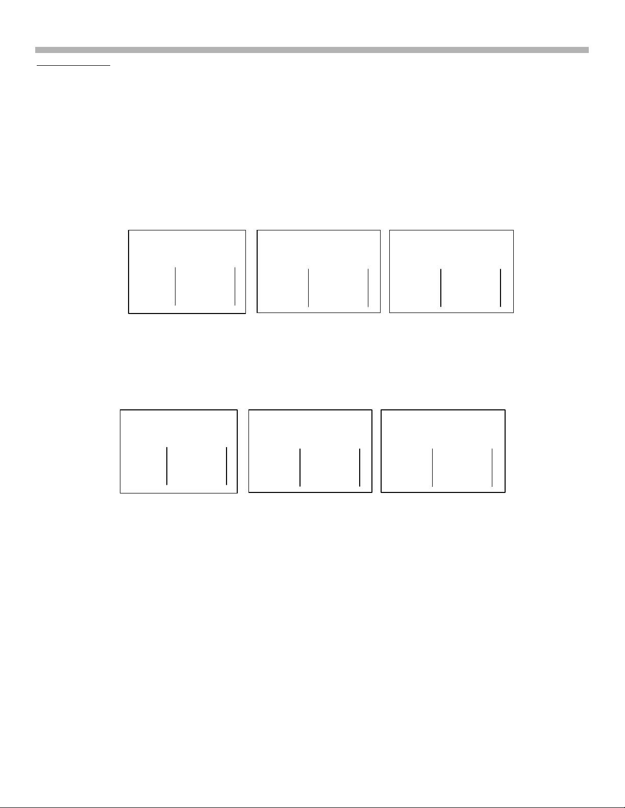
LEVELS - MODEL KZ-32TS1U
White Balance
In the service mode, you will preset the RGB gain levels for the High, Middle and Low color temperatures, then
check the white balance as brightness is increased from minimum to maximum. Figure 7-4 Shows the RGB
levels for the 32" TV and Figure 7-5 shows the levels for the 42" TV. Use the remote control joystick to select and
change the data (position of the x). Store the data by pressing “Mute” and then “Enter”.
Check the white balance as you increase the TV’s brightness level bar from low to middle to high screen brightness.
The white areas of the picture should remain white even as the brightness is changed. If the white balance is off,
return to the stop service mode and touch up the R, G or B adjustment level.
KZ32TS1U
Figure 7-4 shows the White Balance levels from a 32" Plasma TV.
White Balance
Color Temp: High
R
G
B
X
X
X
White Balance
Color Temp: Mid
R
G
B
X
X
X
FIGURE 7-4 - WHITE BALANCE PRESET DEFAULT
KZ-42TS1U
Figure 7-5 shows the White Balance levels from a 42" Plasma TV:
White Balance
Color Temp: High
R
G
B
X
X
X
White Balance
Color Temp: Mid
R
G
B
X
X
X
FIGURE 7-5 - WHITE BALANCE PRESET DEFAULT
LEVELS - MODEL KZ-42TS1U
White Balance
Color Temp: Low
R
G
B
White Balance
Color Temp: Low
R
G
B
X
X
X
X
X
X
14
8. Plasma Panel Replacement - KZ-32TS1U
Chapter 8 - Plasma Panel Replacement - KZ-32TS1U
The KZ-32TS1U and the KZ-42TS1U are mechanically different and have separate procedures for removal
of the Plasma Panel.
Handling Precautions
After removing the plasma panel from the TV, note that there are flex cables located at the bottom and both sides
of the panel that are susceptible to damage.
So the flex cables are not damaged, only rest the plasma panel topside down as shown in figure 8-1.
Bottom
Flex Cables
Panel
Bottom
Flex
Cables
Top
Figure 8-1 - Plasma Panel Standing Upside Down
Procedure – KZ32TS1U
In the steps to follow, you will remove the rear panel, the shield, the board assembly and both support rails to free
the plasma screen that is connected to the front bezel.
15
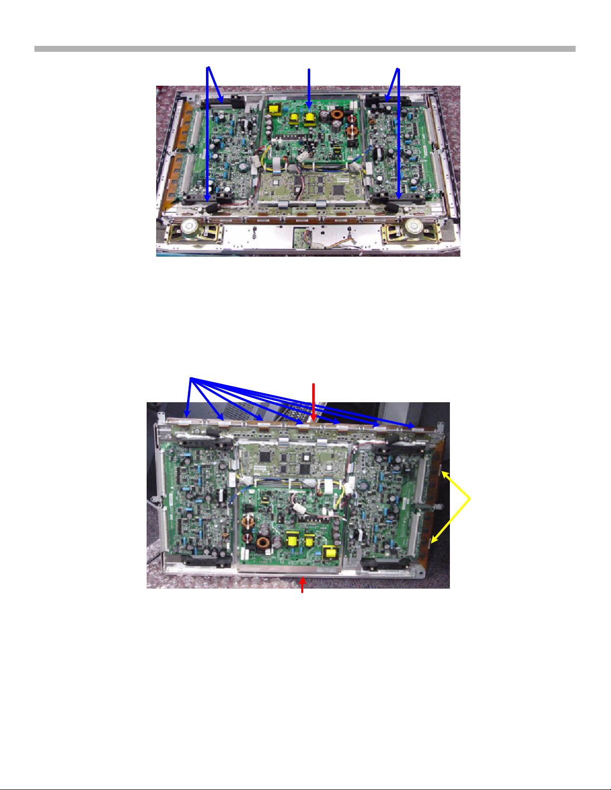
Fan & Shield
Ÿ Remove
8. Plasma Panel Replacement - KZ-32TS1U
Figure 8-2 - Back Removed
a) Begin by removing the back panel to expose the shield, shown in figure 8-2.
b) Unplug the fan and remove the shield.
Plasma
Panel
Power
Supply Board
Lower
Board Assembly
Board
Layout
Figure 8-3 - Circuit Boards
16
TV Board
Assembly
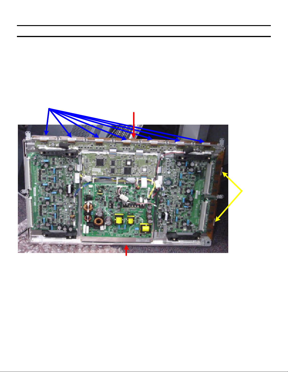
8. Plasma Panel Replacement - KZ-32TS1U
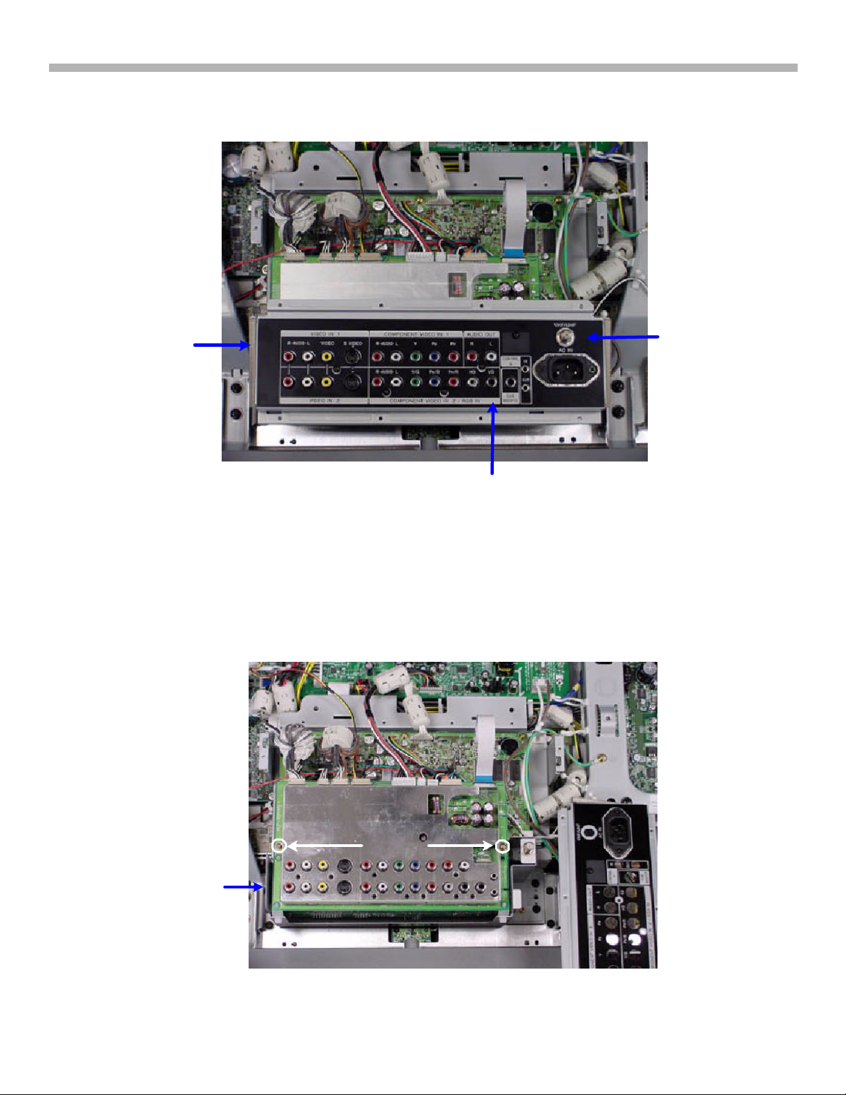
Figure 8-4 - Input Panel
The lower board assembly (behind the input jacks) must be removed because the plasma panel cannot be slid
out from underneath it. There is a lip under the board assembly that prevents the panel from being slid sideways.
c) Remove the input connector cover (four screws + VHF input jack)
TV
Board
Assembly
Ÿ Remove the
Input Connector
Cover
Input
Connector Cover
Screw
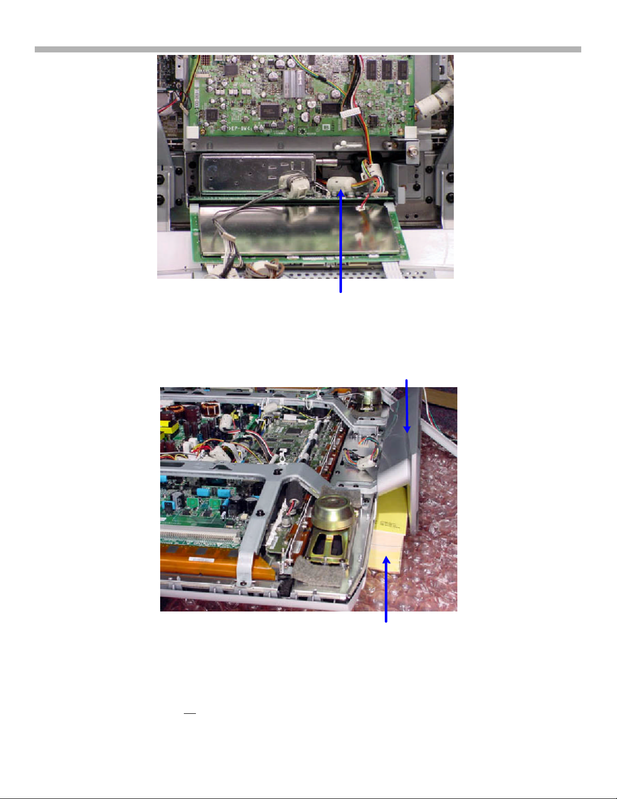
The TV boards are in an assembly held in by four black screws. Two can be easily seen at the right in Figure 8-
5. The left two are behind the plate. In the next three steps, you will lower the front Q board to remove all the
screws and pull out the H1 board cable harness from the assembly.
d) Remove two screws holding the front Q board in the TV board assembly (see Figure 8-5). Fold it down.
e) Remove the four black screws holding the TV board assembly. Gradually pull the assembly toward you.
f) Snake the H1 Board cable harness out the back to free the TV board assembly (see Figure 8-6).
2 Screws
Plate
Remove TV Board Assembly 1
Ÿ Fold Down board
Figure 8-5 - Remove TV Board Assembly 1
17
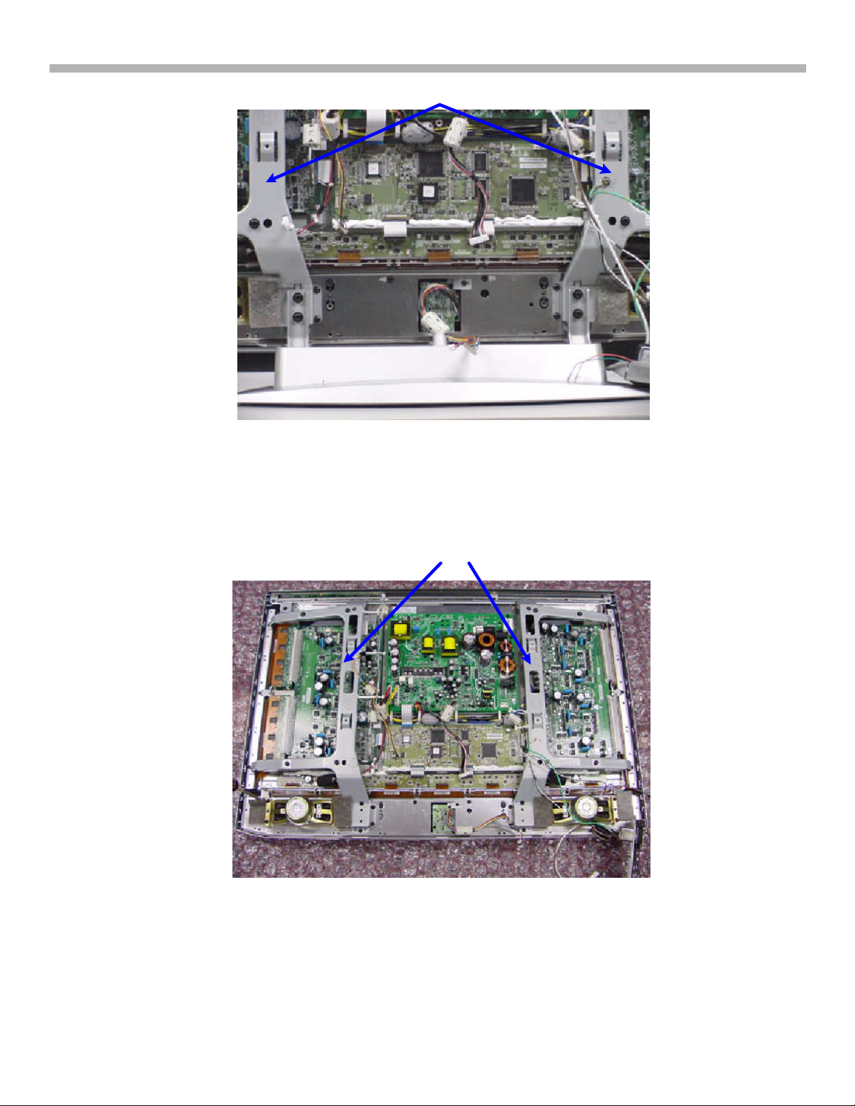
Remove the TV Board Assembly 2
Figure 8-6 - Remove TV Board Assembly 2
Phone
Ÿ Snake the H1 board harness out
the back hole
8. Plasma Panel Replacement - KZ-32TS1U
H1 Board
Cable
Harness
In the next two steps, the TV must be supported while face down and the base removed.
Book(s)
Ÿ Insert Books
Figure 8-7 - Base Removal 1
Phone
Book(s)
g) Lay the TV face down on a clean soft cloth. Bubble wrap was used in these pictures because it was clean
and soft.
h) Use books to lift the base off the floor.
18
Top View
8. Plasma Panel Replacement - KZ-32TS1U
Support
Brackets
Figure 8-8 - Base Removal 1
i) Remove the base.
j) Lay the TV screen flat on the floor.
Bezel, P.S and Plasma Screen
Ÿ Remove bracket
Support
Brackets
Figure 8-9 - Base Removal 2
k) Remove the two support brackets.
19
8. Plasma Panel Replacement - KZ-32TS1U
Figure 8-11 - Plasma Panel Standing Upside Down
Handles
Figure 8-10 - Plasma Screen Handles
Power Supply
Board
Handles
l) Finally, remove the plasma screen – use the four black handles to lift. Only place the top of the plasma
screen down. The other three sides have vulnerable flex cables present.
Bottom
Flex Cables
Panel
Bottom
Top
m) Remove the power supply board (mounted on the larger metal heat sink).
Flex
Cables
20
 Loading...