

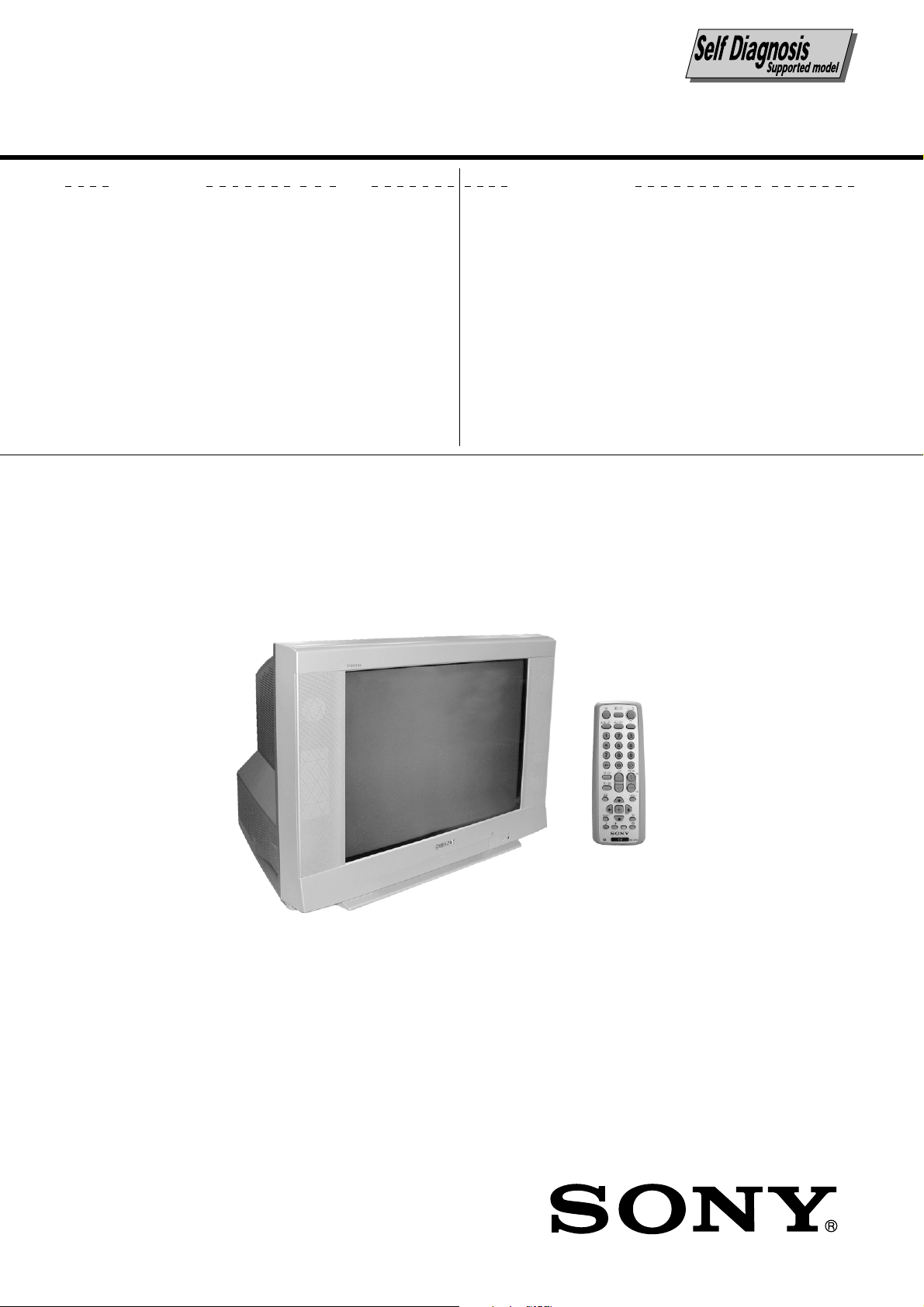
SONY KV-XR25M50, KV-XR25M80 Service Manual

REVISION HISTORY
BX1
CHASSIS
MODEL
KV-XR25M50
KV-XR25M80
KV-XR25M80
NO. SUFFIX DATE SUPPL. / CORR DESCRIPTION
1 -01 2003/12 -- 1st. Issue
PA RT NO. : 9-872-425-01
SERVICE MANUAL
BX1
CHASSIS
MODEL COMMANDER DEST. CHASSIS NO.
KV-XR25M50
KV-XR25M80
KV-XR25M80
RM-W104 E SCC-U98D-A
RM-W104 ME SCC-U90T-A
RM-W104
Saudi Arabia
SCC-VI0K-A
MODEL COMMANDER DEST. CHASSIS NO.
TRINITRON
®
COLOR TV

KV-XR25M50/XR25M80
RM-W104
TABLE OF CONTENTS
Section Title Page
SELF DIAGNOSIS FUNCTION ................................ 3
1. DISASSEMBLY
1-1. Rear Cover Removal ................................................. 6
1-2. Speaker Block Assy Removal................................... 6
1-3. Chassis Assy Removal .............................................. 6
1-4. Service Position ........................................................ 6
1-5. F Board Removal ...................................................... 6
1-6. Terminal Bracket and J1 Board Removal................. 6
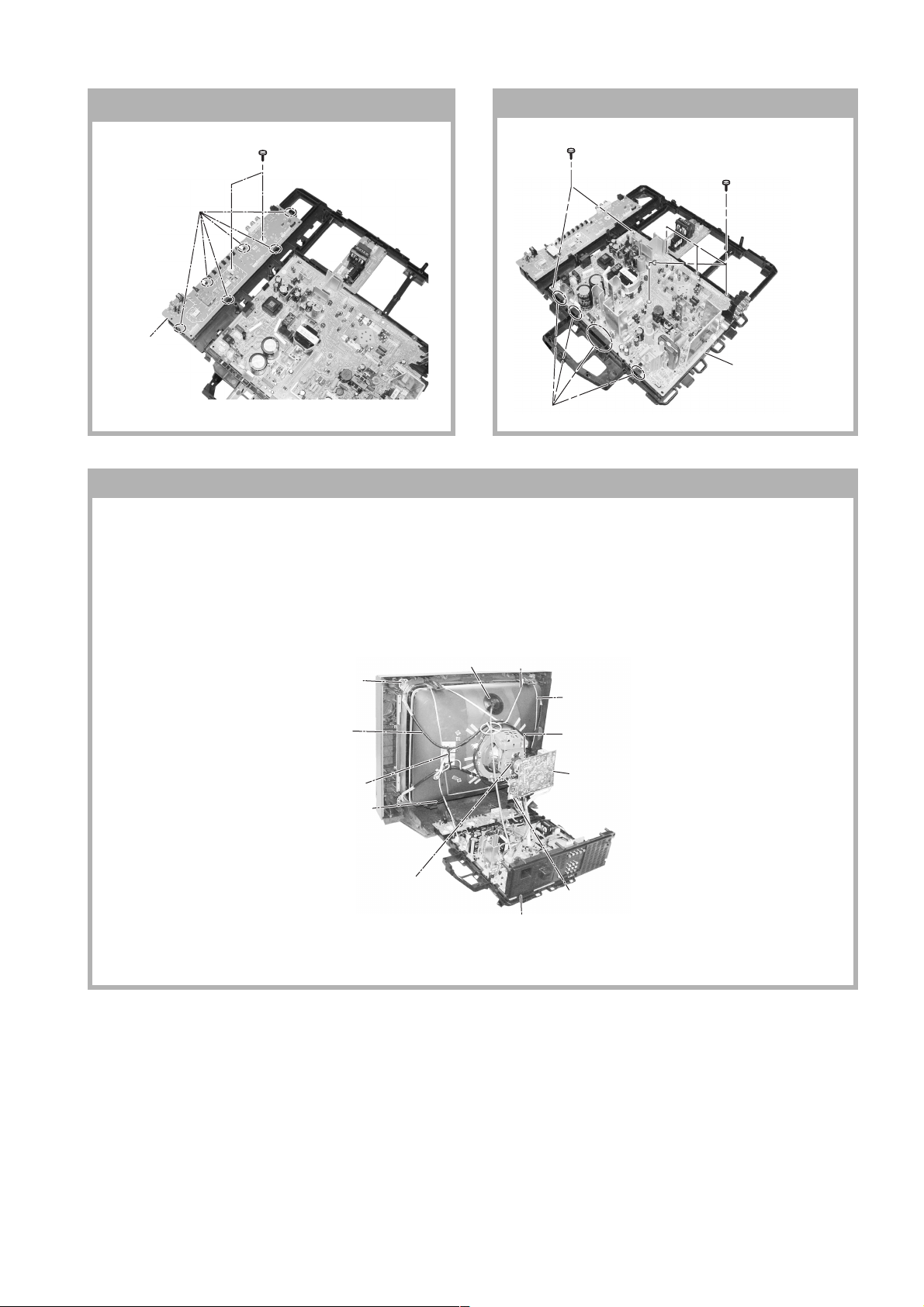
1-7. H3 Board Removal .................................................... 7
1-8. A Board Removal ...................................................... 7
1-9. Picture Tube Removal ............................................... 7
2. SET-UP ADJUSTMENTS
2-1. Beam Landing ........................................................... 9
2-2. Convergence ............................................................ 10
2-3. Focus Adjustment .................................................... 12
2-4. G2 (SCREEN) Adjustments ................................... 12
2-5. White Balance Adjustment ..................................... 12
2-6. Sub Bright Adjustment ........................................... 12
3. CIRCUIT ADJUSTMENTS
3-1. Adjustment With Commander ................................ 13
3-2. Adjustment Method ................................................ 14
3-3. Picture Quality Adjustment .................................... 30
3-4. Deflection Adjustment ............................................ 31
3-5. Picture Distortion Adjustment ................................ 32
Section Title Page
4. DIAGRAMS
4-1. Block Diagram ........................................................ 34
4-2. Circuit Boards Location .......................................... 35
4-3. Schematic Diagram Information ............................ 35
4-3-1. C Board Schematic Diagram ....................... 36
4-3-2. A Board — Processor (Block A) ................. 38
4-3-3. A Board — Audio (Block B) ....................... 40
4-3-4. A Board — Power Supply/Deflection
(Block C) .................................. 42
4-3-5. A Board — Tuner (Block D) ....................... 44
4-3-6. A Board — Jack (Block E) .......................... 46
4-3-7. A Board — Heat Sink (Block F) ................. 48
4-3-8. J1 and F Board Schematic Diagram ............ 49
4-3-9. H3 Board Schematic Diagram ..................... 50
4-3-10. VM Board Schematic Diagram.................. 52
4-4. Voltage Measurement and Waveforms ................... 55
4-5. Printed Wiring Boards and Parts Location ............. 59
4-6. Semiconductors ....................................................... 64
5. EXPLODED VIEWS
5-1. Picture Tube ............................................................ 66
5-2. Chassis ..................................................................... 67
6. ELECTRICAL PARTS LIST .................................... 68
OPERATING INSTRUCTIONS
CAUTION
SHORT CIRCUIT THE ANODE OF THE PICTURE TUBE AND
THE ANODE CAP TO THE METAL CHASSIS, CRT SHIELD,
OR CARBON PAINTED ON THE CRT, AFTER REMOVING THE
ANODE.
SAFETY-RELATED COMPONENT WARNING!!
COMPONENTS IDENTIFIED BY SHADING AND MARK ! ON
THE SCHEMATIC DIAGRAMS, EXPLODED VIEWS AND IN
THE PARTS LIST ARE CRITICAL TO SAFE OPERATION.
REPLACE THESE COMPONENTS WITH SONY PARTS
WHOSE PART NUMBERS APPEAR AS SHOWN IN THIS
MANUAL OR IN SUPPLEMENTS PUBLISHED BY SONY.
– 2 –

KV-XR25M50/XR25M80
SELF DIAGNOSIS FUNCTION
The units in this manual contain a self diagnostis function. If an error occurs, the STANDBY (1) indicator will automatically
begin to flash. The number of times the STANDBY (1) indicator flasher translates to a probable source of the problem. If
an error symptom cannot be reproduced, the remote commander can be used to review the failure occurrence data stored
in memory to reveal past problems and how often these problems occur.
1. DIAGNOSIS TEST INDICATORS
When an errors occurs, the STANDBY/(1) indicator will flash a set number of times to indicate the possible cause of the
problem. If there is more than one error, the indicator will identify the first of the problem areas.
Result for all of the following diagnosis items are displayed on screen. No error has occured if the screen displays a "0".
RM-W104
Diagnosis
Item
Description
• Power does not
turn on
• +B overcurrent
(OCP)*
• I-Port
• IK (AKB)
No. of times
STANDBY/TIMER
lamp flashes
Does not light
2 times
4 times
5 times
Self-diagnostic
display/Diagnosis
result
—
2:0
2:1 ~ 255
4:0
4:1 ~ 255
5:0
5:1 ~ 255
Probable
Cause
Location
• Power cord is not plugged
in.
• Fuse is burned out (F4601)
(A Board)
• H.OUT (Q511) is shorted.
(A board)
• IC751 is shorted.
(C/CV Board)
• +13V is not supplied.
(A Board)
• IC503 voltage list is faulty.
(A Board)
• Video OUT (IC751) is faulty.
(C Board)
• IC001 is faulty. (A Board)
• Screen (G2) is improperly
adjusted.
Detected
Symptoms
• Power does not come on.
• No power is supplied to the
TV.
• AC power supply is faulty.
• Power does not come on.
• Load on power line is
shorted.
• Has entered standby state
after horizontal raster.
• Vertical deflection pulse is
stopped.
• Power line is shorted or
power supply is stopped.
• No raster is generated.
• CRT cathode current
detection reference pulse
output is small.
• HV Protect
Note 1: If a + B overcurrent is detected, stoppage of the vertical deflection is detected simultaneously.
The symptom that is diagnosed first by the microcontroller is displayed on the screen.
Note 2: Refer to screen (G2) Adjustment in section 2-4 of this manual.
8 times
8:0
8:1 ~ 255
• IC604 faulty.
• IC607 faulty.
• No power supply to CRT
ANODE.
• No RASTER is generated.
– 3 –
KV-XR25M50/XR25M80
RM-W104
2. DISPLAY OF STANDBY/(1) indicator FLASH
COUNT
Lamp ON 300ms
Lamp OFF 300ms
Lamp OFF 3 sec
3. STOPPING THE STANDBY/(1) indicator FLASH
Turn off the power switch on the TV main unit or unplug the power cord from the outlet to stop the STANDBY/(1) lamp
from flashing.
Diagnosis Item Flash Count*
+B overcurrent 2 times
I-Prot 4 times
IK (AKB) 5 times
HV Protect 8 times
* One flash count is not used for self-diagnosis.
FLASH RED n Please refer diagnosis item.
FLASH GREEN n OK
STANDBY indicator
4. SELF-DIAGNOSTIC SCREEN DISPLAY
For errors with symptoms such as "power sometimes shuts off" or "screen sometimes goes out" that cannot be confirmed,
it is possible to bring up past occurrence of failure on the screen for confirmation.
[To Bring Up Screen Test]
In standby mode, press buttons on the remote commander sequentially in rapid succession as shown below:
[display] / channel [5] / volume [-] / Power
/ TV
˘
Note that this differs from entering the service mode (volume [+]).
Self-Diagnostic screen display
SELF DIAGNOSTIC
2 : 0
3 : N/A
4 : 0
5 : 1
8 : 0
101 : N/A
Numeral "0" means that no fault was detected.
Numeral "1" means the number of a fault occurrence (1~255).
– 4 –
KV-XR25M50/XR25M80
5. HANDLING OF SELF-DIAGNOSTIC SCREEN DISPLAY
Since the diagnosis results displayed on the screen are not automatically cleared, always check the self-diagnostic screen
during repairs. When you have completed the repairs, clear the result display to "0".
Unless the result display is cleared to "0", the self-diagnosis function will not be able to detect subsequent faults after
completion of the repairs.
[Clearing the result display]
To clear the result display to "0", press buttons on the remote commander sequentially when the self-diagnostic screen is
displayed, as shown below:
Channel [8] / "0"
[Quitting Self-diagnostic screen]
To quit the entire self-diagnostic screen, turn off the power switch on the remote commander or the main unit.
6. SELF-DIAGNOSIS CIRCUIT
RM-W104
FROM
C BOARD
IC751 PIN 5
A BOARD
FROM
Q511
COLLECTOR
A BOARD
IC001
Y/CHROMA JUNGLE
IK
97
EHTO
A BOARD
IC503
V.OUT
F.B-PLS
A BOARD
IC001
SYSTEM
SDA1
3 11645
V.GUARD
RED LED
20
7
DISPLAY
A BOARD
IC003
MEMORY
5
SDA
[+B overcurrent OCP ] Occurs when an overcurrent on the +B (135V) line is detected by pin 97 of IC001
(A Board). If the voltage of pin 97 of IC001 (A Board) is less than 1V when V.SYNC is
more than HV, the unit will automatically go to standby.
[I-Port] Occurs when an absence of the vertical deflection pulse is detected by pin 116 of
IC001 (A Board).
[IK $AKB%] If the RGB levels* do not balance within 15 sec after the power is turned on, this error
will be detected by IC001 (A Board). TV will stay on, and indicalor will start to Blink 5
times.
[HV Protect] Occurs when IC001 internal HV protect detects an abnormal. H-Pulse (frequency) due
to unproper power supply to IC001. TV cuts off high voltage power of anode CRT. No
picture will be detected eg IC607, IC604 go faulty.
* (Refers to the RGB levels of the AKB detection Ref pulse that detects 1K)
– 5 –
KV-XR25M50/XR25M80
RM-W104
SECTION 1
DISASSEMBLY
1-1. REAR COVER REMOVAL
2 Rear cover
1 Eleven screws
(+BVTP 4 × 16)
Type 2 IT-3
1-2. SPEAKER BLOCK ASSY REMOVAL
1 Two screws
(Washer Head)
(+P4 × 16)
1-3. CHASSIS ASSY REMOVAL 1-4. SERVICE POSITION
1-5. F BOARD REMOVAL
2 F Board
1 Two hooks
– 6 –
1-6.
TERMINAL BRACKET AND J1 BOARD REMOVAL
7 J1 Board
2 One screws
(+BVTP 3 × 12)
Type 2 IT-3
1 One screws
(+BVTP 3 × 12)
Type 2 IT-3
6 Two hooks
5 Terminal bracket
3 One screws
(+BVTP 4 × 16)
Type 2 IT-3
4 Two screws
(+BVTP 3 × 12)
Type 2 IT-3
KV-XR25M50/XR25M80
RM-W104
1-7. H3 BOARD REMOVAL
1 Six Hooks
2
H3 Board
1-8. A BOARD REMOVAL
2 Two screws
washer head
(+P 3 × 12)
3 Four Hooks
1 Four screws
(3 × 12)(+BVTAP)
4 A Board
1-9. PICTURE TUBE REMOVAL
Note:
• Please make sure the TV set is not in standing position before removing necessary CRT support located on bottom
right and left.
1) Place the TV set with the CRT face down on a cushion jig.
2) Remove the rear cover.
3) Remove the Speaker Block Assy.
4 Anode Cap Removal
qg Screw Tapping 7+
Crown washer
qf Degaussing Coil
qd Holder, DGC(2) Removal
0 Spring Tension(2) Removal
8 Loosen the Deflection Yoke
fixing screw and remove
qs Band, DGC Removal
qa Earth Coating Assy
6 Loosen the Neck Assembly
fixing screw and removal
5 C Board Removal
7 VM Board Removal
9 Chassis Assy Removal
– 7 –
KV-XR25M50/XR25M80
c
RM-W104
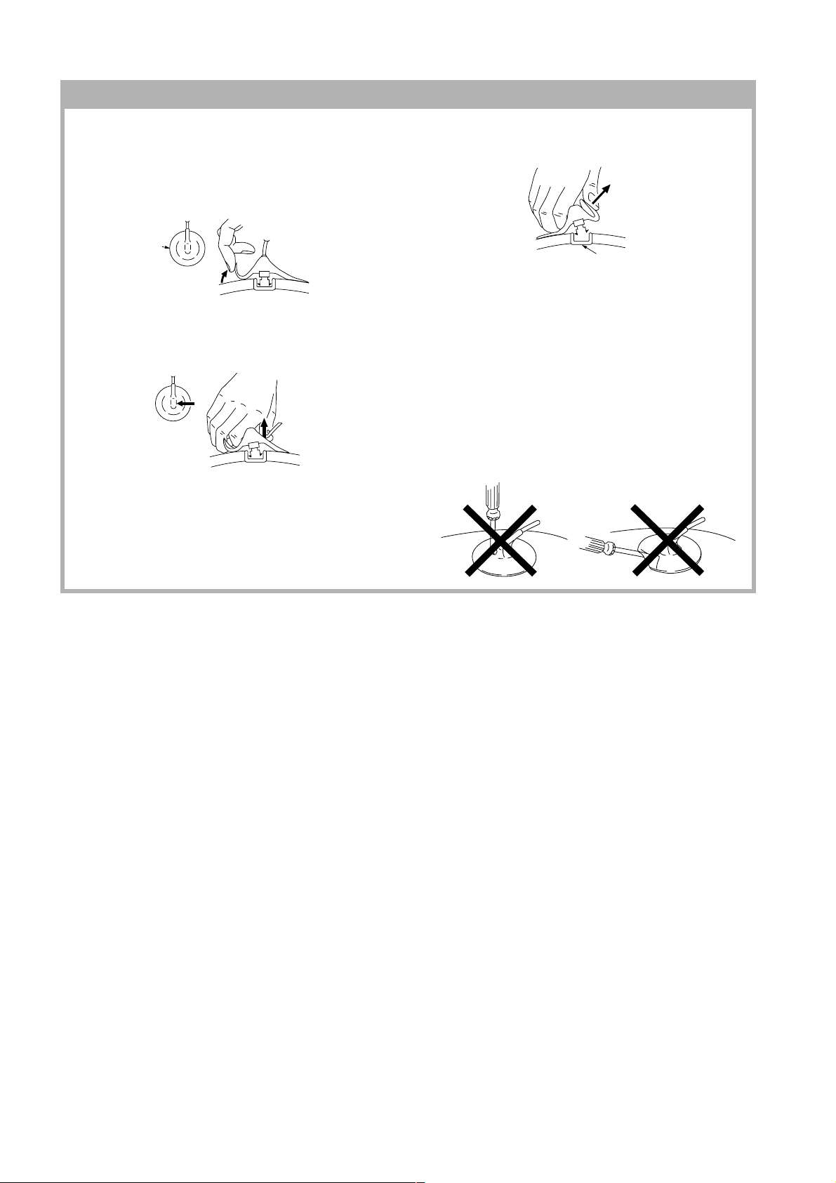
• REMOVAL OF ANODE-CAP
Note:
• After removing the anode, short circuit the anode of the picture tube and the anode cap to the metal chassis, CRT
shield or carbon paint on the CRT.
• REMOVING PROCEDURES
a
1 Turn up one side of the rubber cap in the direction
indicated by the arrow a.
2 Using a thumb pull up the rubber cap firmly in the direc-
tion indicated by the arrow b.
a
3 When one side of the rubber cap is separated from the
anode button, the anode-cap can be removed by
turning up the rubber cap and pulling it up in the
direction of the arrow c.
• HOW TO HANDLE AN ANODE-CAP
1 Do not damage the surface of anode-caps with
sharp shaped objects.
anode button
b
b
2 Do not press the rubber too hard so as not to
damage the inside of anode-cap.
A metal fitting called the shatter-hook terminal is
built into the rubber.
3 Do not turn the foot of rubber over too hard.
The shatter-hook terminal will stick out or damage
the rubber.
– 8 –
SECTION 2
SET-UP ADJUSTMENTS
KV-XR25M50/XR25M80
RM-W104
The following adjustments should be made when a
complete realignment is required or a new picture tube is
installed.
Set the controls as follows unless otherwise noted:
VIDEO MODE: .................................................... Standard
PICTURE CONTROL:......................................... Normal
BRIGHTNESS CONTROL: ................................. Normal
Preparation :
• In order to reduce the influence of geomagnetism on
the set's picture tube, face it east or west.
• Switch on the set's power and degauss with the
degausser.
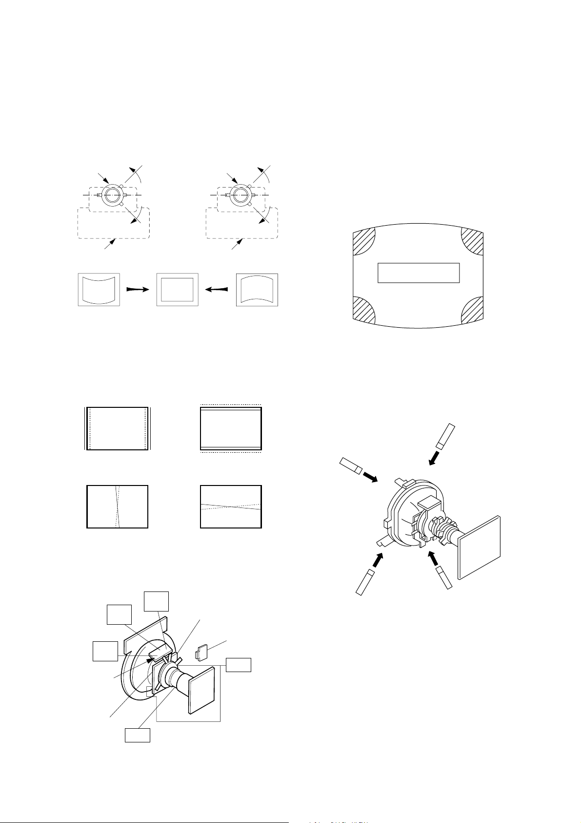
2-1. BEAM LANDING
PICTURE MODE: DYNAMIC
1. Input a white signal with the pattern generator.
Contrast
Brightness
}
normal
2. Position neck assy as shown in Fig 2-1.
3. Set the pattern generator raster signal to a green
raster.
4. Move the deflection yoke to the rear and adjust with
purity control so that the green is at the center and the
blue and the red take up equally sized areas on each
side. (Figures 2-1 through 2-4.)
5. Move the deflection yoke forward and adjust so that the
entire screen is green. (Figure 2-2.)
6. Switch the raster signal to blue, then to red and verify
the condition.
7. When the position of the deflection yoke have been
decided, fasten the deflection yoke with the screws and
DY spacers.
8. If the beam does not land correctly in all the corners,
use a magnet to adjust it.
(Figure 2-5.)
Perform the adjustments in the following order :
1. Beam Landing
2. Convergence
3. Focus
4. Screen(G2)
5. White Balance
Note : Test Equipment Required.
1. Pattern Generator
2. Degausser
3. DC Power Supply
4. Digital Multimeter
5. Oscilloscope
Purity control
Fig. 2-3
Blue
Red
Green
Fig. 2-4
Purity control
corrects this area.
b
a
Disk magnets or rotatable
disk magnets correct these
areas (a-d).
Neck assy
Align the edge of
the neck assy with
the edge of the G2 grid.
G2G1 G3
Fig. 2-1
Fig. 2-2
– 9 –
c
Deflection yoke positioning
corrects these areas.
a
d
d
Fig. 2-5
b
c
KV-XR25M50/XR25M80
RM-W104
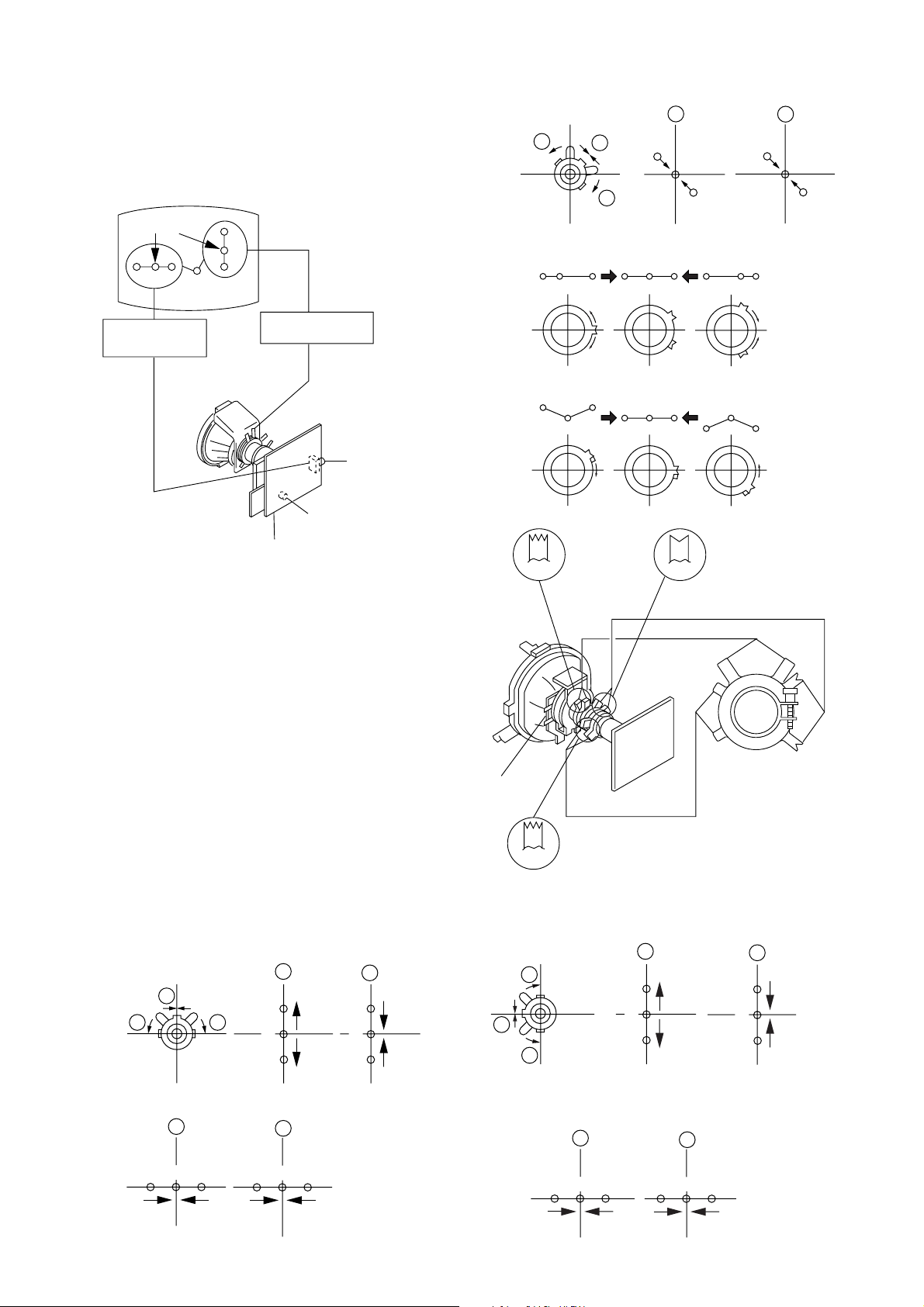
2-2. CONVERGENCE
• Before starting this adjustment, adjust the focus,
horizontal size and vertical size.
• Receive dot/hatch signal
• Pic mode: Soft
Center dot
R G B
H. STAT VR
R
G
B
V. STAT
Magnet
RV705
H. STAT
RV1800
SCREEN (G2)
C Board
(1) Horizontal and Vertical Static Convergence
1. (Moving vertically), adjust the V.STAT magnet so that
the red, green and blue dots are on top of each other
at the centre of the screen.
2. (Moving horizontally), adjust the H.STAT VR control so
that the red, green and blue dots are on top of each
other at the center of the screen.
3. If the H.STAT variable resistor cannot bring the red,
green and blue dots together at the center of the
screen, adjust the horizontal convergence with the
H.STAT variable resistor and the V.STAT magnet in the
manner given below.
(In this case,the H.STAT variable resistor and the
V.STAT magnet influence each other so be sure to
perform adjustments while tracking).
4. BMC (Hexapole) Magnet.
If the red, green and blue dots are not balanced or
aligned, then use the BMC magnet to adjust in the
manner described below.
1 V. STAT
a
b b
a
B
G
R
b
B
G
R
3 H. STAT
b
a
b
a
R
G
B
B
G
4 BMC (Hexapole) magnet
RG B R G B R GB
RB
G
Purity
DY pocket
V.STAT
5. Operatio of V.STAT magnet
If the V.STAT magnet is moved in the "a" and "b" arrows,
the red, green and blue dots moves as shown below.
b
a
b
RG
V.STAT
B
G
R
BMC
BMC (Hexapole)
Purity
a
GB
RB
b
B
G
R
b
R
2 H. STAT VR
a
RGGBB
6. Moved RV705 H.STAT.
b
R
The red, green and blue dots move as shown below.
a
RGGBB
b
R
– 10 –
KV-XR25M50/XR25M80
RM-W104
7. Y separation axis correction magnet adjustment.
1. Receive the cross-hatch signal and adjust
[PICTURE] to [MIN] and [BRIGHTNESS] to
[STANDARD] .
2. Adjust the Y separation axis correction magnet
on the neck assembly so that the horizontal lines
at the top and bottom of the screen are straight.
Neck assy Neck assy
VM1 board VM1 board
Blue
Red Blue
Red
(2) Dynamic Convergence Adjustment
Preparation:
Before starting this adjustment, adjust the horizontal and
the vertical static convergence
TLV Rotate TLV-2 VOL (29", 34") on DY
XCV Rotate XCV Adj core on DY
YCH Rotate YCH VOL on DY
TLH Insert TLH Correction Plate to DY Pocket
(Left or Right)
(3) Screen-corner Convergence
If you are unable to adjust the corner convergence
properly, this can be corrected with the use Piece A(90)
Conv. Correct.
ba
a-d : screen-corner
misconvergence
cd
1. Affix the Permalloy Assy Correction corresponding to the
misconverged areas.
RB
ON DY:
B
R
TLH TLV
RB
R
B
YCH XCV
(VR1)
(VR2)
YCH
(VR3)
TLV
TLV
DY pocket
TLH Plate
XCV
Fix a Permalloy assy
corresponding to the
misconverged areas
a
d
b
c
a to d : permalloy assembly
DY pocket
XCV
– 11 –
KV-XR25M50/XR25M80
RM-W104
2-3. FOCUS ADJUSTMENT
FOCUS adjustment should be completed before W/B
adjustment.
(Except 34")
1. Receive digital monoscope pattern.
2. Set "Picture Mode" to "DYNAMIC".
3. a) Adjust focus VR so that the center of screen
becomes just focus(29", 34").
b) Adjust focus VR so that the lion teeth
becomes just focus(25").
4. Change the receiving signal to white pattern and blue
back.
5. Confirm Magenta ring is not noticeable. In case
magenta ring is obvious, adjust FOCUS VR to balance
between MAGENTA RING and FOCUS.
2-5. WHITE BALANCE ADJUSTMENT
1. Set to Service Mode (Refer Section 3-1:
ADJUSTMENTS WITH COMMANDER).
2. Input white raster signal.
3. Set Picture to DYNAMIC.
i. Set PICT 006 WTS to 00h (all models except AR2
series).
ii. For AR2 set OPTB 006 OPB 6 to 00.
4. Select WHBL 002"RDRV" and adjust the value to 37
5. Select WHBL 003"GDRV" and 004 "BDRV"and adjust
the data for the best white balance in highlight
condition.
6. Adjust WHBL 000 "BKOR" and 001 "BKOG"and adjust
the data for best white balance cut-off condition.
7. Write into the memory by pressing [MUTING] then
-.
8. Write offset data for other mode.
After adjustment, please reset:
i. OPTM 006 – OPB 6 to original data (AR2 series).
ii. PICT 006 – WTS to original data (All models except
AR2 series)
Adjust Offset Offset
18000 t 12363 t 9300
BKOR –2 –3
BKOG +1 +2
RDRV 0 0
GDRV –3 –8
BDRV –8 –18
Focus
Screen
FLYBACK TRANSFORMER (T507)
2-4. G2 (SCREEN) ADJUSTMENTS
1. Set the PICTURE to Normal.
2. Put the VIDEO input mode without signals
3. Connect R,G,B of the C board cathode to the
oscilloscope.
4. Adjust cathode voltage to the value below.
5. Adjust G2 (screen) on the FBT until picture shows the
point before cut off.
Cathode setting voltage:
170 V ± 2 (VDC)
2-6. SUB BRIGHT ADJUSTMENT
1. Set to service mode.
2. Brightness set to 50%, Picture: Minimum.
3. Select WHBL SBRT with 1 and 4, and adjust 'SBRT'
data with
3 and 6 so that the third stripe from right
dimly lit.
4. Write into the memory by pressing [MUTING] then -.
5. Models cut-off: 0 IRE (25" and 34")
10 IRE (29")
Slightly Glimmer: 10 IRE (25" and 34")
20 IRE (29")
– 12 –

KV-XR25M50/XR25M80
SECTION 3
CIRCUIT ADJUSTMENTS
3-1. ADJUSTMENTS WITH COMMANDER
Service adjustments to this model can be performed using the supplied remote commander RM-W104.
a. ENTERING SERVICE MODE
With the unit on standby
t [DISPLAY] t 5 t [VOL $+% ] t [POWER]
This operation sequence puts the unit into service mode.
This screen display is:
RM-W104
category in decimal item name in decimal NG service command frequency video input name
GEOM 006 HSIZ 031 x SERVICE 60 S VIDEO 1
release ID version in binary for factory color system (decimal?)
SUS01 0.69U 0001 1111 FF FF NTSC3 65535
111 11 11 1 7 11 FG xy 111 000000 000000
S : for Sony
A:Aiwa
U S : US/Latin/Taiwan
E U : Europe
G A : General Area
J P : Japan
item no. service data NVM field channel no./
software service data reserved power on time
Status Byte Status Byte
Flash DCXO #1 SSD #2 SSD
VDSP_C Flag
CO_LOCKED
VDSP
Detected Stereo Type (Direct Value from CZ_ Stereo_Mode)
111 Needed for Nicam DCXO aligment Purpose
xy Value of x = 0 - Unknown, 1 - BTSC, 2 - A2, 3 - NICAM,
4 - KOREAN, 5 - Japan, 6 - AV Stereo
Value of y = 0 - Mono, 1 - Stereo, 2 - Bilingual, 4 - SAP/Single
0 1 : serial no. of the M/P release
for each destination
b. METHOD OF CANCELLATION FROM SERVICE MODE
Set the standby condition (Press [POWER] button on the commander), then press [POWER] button again, hereupon it
becomes TV mode.
c. METHOD OF WRITE INTO MEMORY
1. Set to Service Mode.
2. Press
3. Change item by pressing
1 (UP) and 4 (DOWN), to select the adjustment item.
3, 6.
4. Press [MUTING] button to indicate WRITE on the screen.
5. Press
- button to write into memory.
1, 4 Select the adjustment item.
r
3, 6 Raise/lower the data value.
r
[MUTING] Writes.
r
- Executes the writing.
d. MEMORY WRITE CONFIRMATION METHOD
1. After adjustment, pull out the plug from AC outlet, and then plug into AC outlet again.
2. Turn the power switch ON and set to Service Mode.
3. Call the adjusted items again to confirm adjustments were made.
– 13 –

KV-XR25M50/XR25M80
RM-W104
e. OTHER FUNCTION VIA REMOTE COMMANDER
7, - All the data becomes the values in memory.
8, - All user control goes to the standard state.
[Display], - Service data initialization (Be sure not to use usually.)
2, 5 Select Device or Category (Up, Down)
3-2. ADJUSTMENT METHOD
Item Number 000 HPOS
This explanation uses H POSITION as an example.
1. Select "000 HPOS" with the
2. Raise/lower the data with the
3. Select the optimum state. (The standard is IF for PAL reception.)
4. Write with the [MUTING] button. (The display changes to WRITE.)
5. Execute the writing with the
SERVICE.)
Example on screen display :-
1 and 4 buttons, or 2 and 5.
3 and 6 buttons.
- button. (The WRITE display will be changed to red color while excuting, and back to
GEOM 00
1.0C
637S
GEOM 00
637S 1.0C
Write with [MUTING]
GEOM 00
1.0C
637S
Write executed with -
Use the same method for all Items. Use
[MUTING], then execute the write with
1F 50HPS
SERVICE
7F 0 000A59
1F WRITE
7F 0 000A59
WRITE
1F 50HPS
7F 0 000A59
1 and 4 to select the adjustment item, use 3 and 6 to adjust, write with
-.
GREEN
Adjusted with 3
and 6 buttons.
50HPS
GREEN
RED
The WRITE display
then the display
returns to green
SERVICE.
Note :1.In [WRITE], the data for all items are written into memory together.
2. For adjustment items that have different standard data between 50Hz or 60Hz, be sure to use the respective
input signal after adjustment.
– 14 –
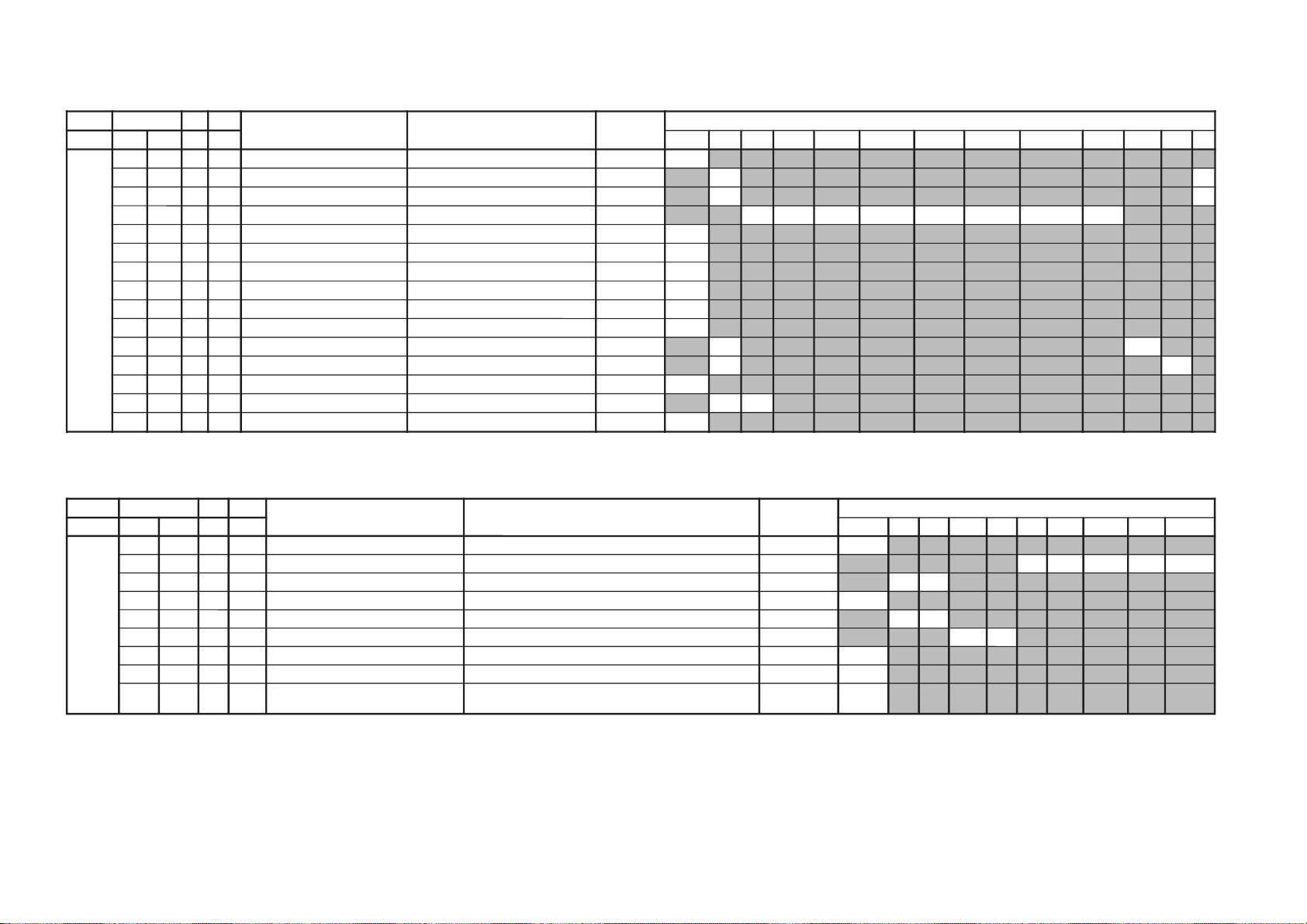
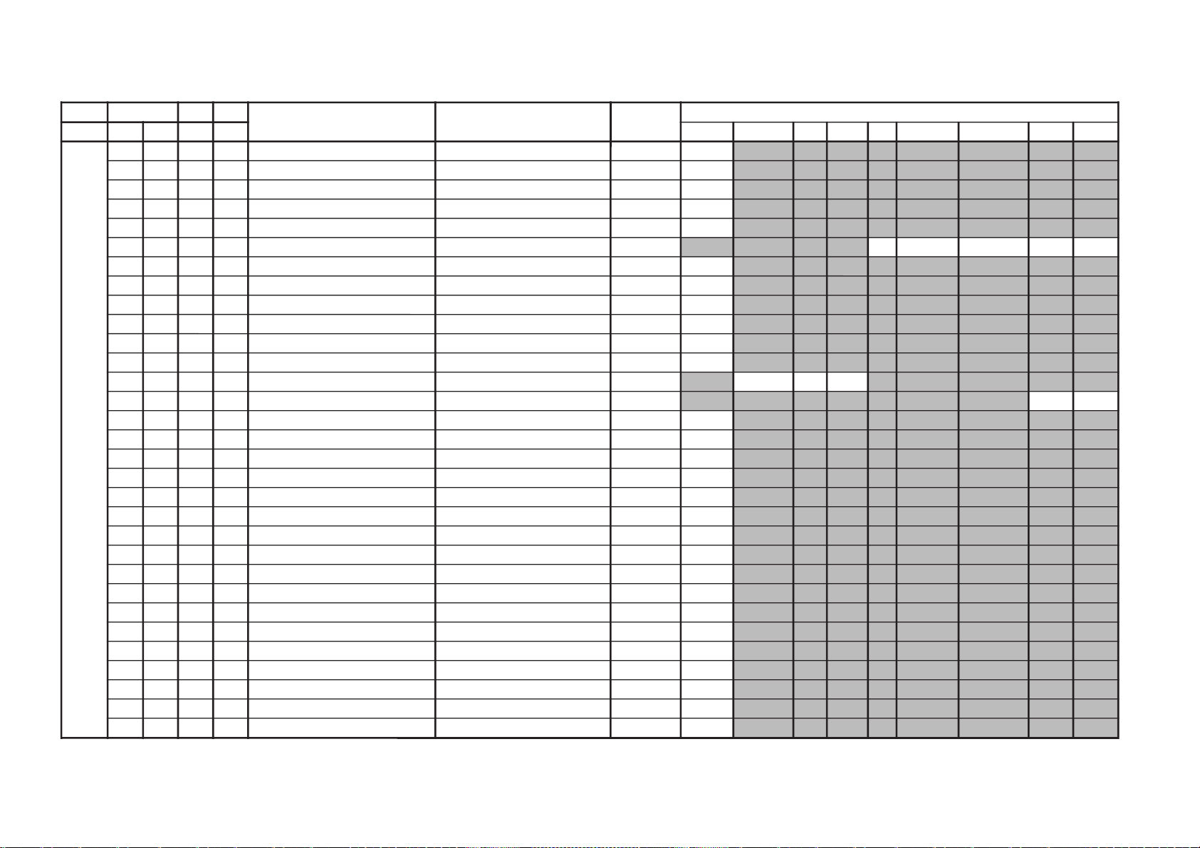
Adjustment Item Table
JVTytilanoitcnuF.tinIegnaRnoitcnuFetoN&elbaTemaNeciveD)deliateD(eulaVlaitinI/sserddAMVN
yrogetaC.oNemaNceDceD )sserddAevalS(nommoC050605w06w
MOEG000SOPH130360)SH(tfihSlatnoziroH )BGRNPJ+(06w/05w/06/05rossecorP-VT
13131313
100RAPH130360margolellaraPlatnoziroH06w/05w/06/05)hA8(
13131313
200WOBH130360woBlatnoziroH06w/05w/06/05
13131313
300NILV130360ytiraeniLlacitreV06w/05w/06/05
13131313
400RCSV130360llorcSlacitreV06w/05w/06/05
13131313
500ZISH130360)WE(htdiWWE )BGRNPJ+(06w/05w/06/05
13131313
600WPWE130360)WP(htdiW/alobaraPWE06w/05w/06/05
13131313
700POCU710360alobaraPrenroCreppUWE06w/05w/06/05
71717171
800POCL710360alobaraPrenroCrewoLWE06w/05w/06/05
71717171
900ZTWE130360muizeparTWE06w/05w/06/05
13131313
010PLSV130360)SV(epolSlacitreV06w/05w/06/05
13131313
110ZISV510360edutilpmAlacitreV06w/05w/06/05
51515151
210ROCS410360)CS(noitcerroC-S06w/05w/06/05
41414141
310SOPV130360)HSV(tfihSlacitreV06w/05w/06/05
13131313
410LBH000100edoMgniknalBBGR06w/05w/06/05
10101010
510FBW700510)FBW(gniknalBediWfognimiT06w/05w/06/05
80508050
610RBW700510)RBW(gniknalBediWfognimiT06w/05w/06/05
90019001
710LBS000100gniknalBecivreSenon00
810YPOC000100aeraMVNzH06/05llaotatadOEGehtypoCenon00
– 15 –
KV-XR25M50/XR25M80
RM-W104
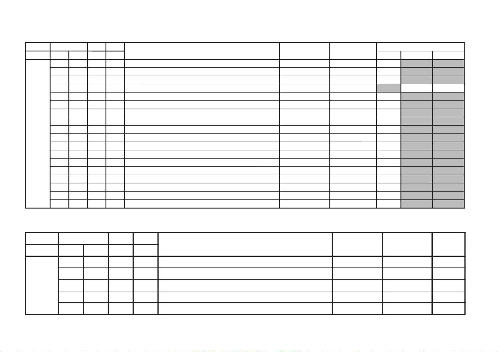
KV-XR25M50/XR25M80
JVTytilanoitcnuF.tinIegnaRnoitcnuFetoN&elbaTemaNeciveD )deliateD(eulaVlaitinI/sserddAMVN
yrogetaC.oNemaNceDceD
)sserddAevalS(nommoCpmeTloC
)rehtoHGIH(
pmeTloC
)rehtoWOL(
pmeTloC
)rehtoMRON(
pmeTloC
)VUYHGIH(
pmeTloC
)VUYWOL(
pmeTloC
)VUYLAMRON(
pmeTloC
)BGRHGIH(
pmeTloC
)BGRWOL(
pmeTloC
)BGRMRON(
srehtOBGRVUYedomciP
0
edomciP
1
edomciP
2
edomciP
3
LBHW
000ROKB
130360Btesffo,)00=BFO(RtesffOleveLkcalB
)10=BFO(
)srehtO/BGR/VU(*)lamroN/WOL/HGIH(pmetloc
rossecorP-VT
131313131313131313
100GOKB130360GtesffOleveLkcalB )srehtO/BGR/VU(*)lamroN/WOL/HGIH(pmetloc)hA8(
020202020202020202
200VRDR730360RtnioPetihW )srehtO/BGR/VU(*)lamroN/WOL/HGIH(pmetloc)HA8(orP-VT
737373737373737373
300VRDG730360GtnioPetihW )srehtO/BGR/VU(*)lamroN/WOL/HGIH(pmetloc
542473542473542473
400VRDB730360BtnioPetihW )srehtO/BGR/VU(*)lamroN/WOL/HGIH(pmetloc
840403840403840403
500GPL000100teserPniaGBGR enon00
600RGP130721)RGP(RniaGteserP enon**
700GGP130721)GGP(GniaGteserP enon**
800BGP130721)BGP(BniaGteserP enon**
900FONG000510tesffOniaGteserP enonpoolCCC01
010TRBS130360ssenthgirB-buS VUY/BGR/srehtO
838383
110ORBS000300)ciPtnegilletnI(tesffOssenthgirB-buS enon00
210LGE000100metsySCCCnipooLniaGelbanE enon00
310LGS000300metsySCCCnitnerruChgiHfonoitceleS enon00
410BKA000100noitazilibatStnerruCkcalB enon00
510SBC000100gnitimiLtnerruCmaeBfoecneuqeSlortnoC enon00
610BBGR000300gniknalBBGR enon00
710GBLB000100tuptuOneerG&eulBfogniknalB enon00
810BFO000100eulBtesffOleveLkcalB enon10
910RBSN000510tesffOssenthgirBdradnatSnoN enon00
020PBW000300)woL:3,2,lamroN:1,hgiH:0(gnitteSpmeTroloC edoMerutciP
00102010
JVTytilanoitcnuF
.tinIegnaRnoitcnuFetoN&elbaTemaNeciveD )deliateD(eulaVlaitinI/sserddAMVN
yrogetaC.oNemaNceDceD
)sserddAevalS(nommoCVUYlap05
)VT(
lap05
)oediV(
maces05
)VT(
maces05
)oediV(
VT06oediV06VUY05VUY06BGR05BGR06edomciP
0
edomciP
1
edomciP
2
edomciP
3
ocE*cimanyD
)npJ(dts
ocE*cimanyD
)npJ(hcum
ocE*dradnatS
)npJ(dts
ocE*dradnatS
)npJ(hcum
dtsocE
)npJ(
hcumocE
)npJ(
VToediVVT
ediW
oediV
ediW
MVA
)npJ(
ediWVA
)npJ(
JDAS000XAMP360360mumixaMerutciP )BGRNPJ+(>ediW/lamroN</)ediW/lamroN(*)oediV/VT( rossecorP-VT
448344830000
100EUHS700510euH-buS oediV/VT
2090
200PHSS510360ssenprahS-buS )BGRNPJ+(VUY/oediV/VT
**
****
300OHSS000300)ciPtnegilletnI(tesffOssenprahS-buS enon30
400LOCS130360roloC-buS /)oediv(maces05/)vt(maces05/)oediv(lap05/)vt(lap05
BGR06/BGR05/VUY06/VUY05/oediv06/VT06
92039203923392330000
500OOCS000300)ciPtnegilletnI(tesffOroloC-buS enon10
600CIP130721
;)dilavni(001>,)dilav(001-0:AG[lortnoCerutciP
])dilavni(6tiberongi;)dilav(36-0:srehtO
)ataDteseRresU=lanosreP:AG(ledoMerutciP
0010957001
700LOC130721
;)dilavni(001>,)dilav(001-0:AG[lortnoCroloC
])dilavni(6tiberongi;)dilav(36-0:srehtO
)ataDteseRresU=lanosreP:AG(ledoMerutciP
**055405
800TRB130721
,)dilav(001-0:AG[lortnoCssenthgirB
tiberongi;)dilav(36-0:srehtO;)dilavni(001>
])dilavni(6
)ataDteseRresU=lanosreP:AG(ledoMerutciP
84050505
900EUH130721
;)dilavni(001>,)dilav(001-0:AG[lortnoCeuH
])dilavni(6tiberongi;)dilav(36-0:srehtO
)ataDteseRresU=lanosreP:AG(ledoMerutciP
05050505
010PHS130721
,)dilav(001-0:AG[lortnoCssenprahS
tiberongi;)dilav(36-0:srehtO;)dilavni(001>
])dilavni(6
)ataDteseRresU=lanosreP:AG(ledoMerutciP
06555405
RM-W104
– 16 –
NOTE:
• Remark ‘**’ please refer page 25.
NOTE:
• Remark ‘**’ please refer page 25.
JVTytilanoitcnuF.tinIegnaRnoitcnuFetoN&elbaTemaNeciveD )deliateD(eulaVlaitinI/sserddAMVN
yrogetaC.oNemaNceDceD )sserddAevalS(nommoCsrehtOVUY)VT(LAP)VT(CSTN)VT(MACES)oediV(LAP)oediV(CSTN)oediV(MACESTUPNI-SMACESCSTNVT
CY000QRFP000300yaleDdnaycneuqerFretneCgnikaeP rossecorP-VT00
100APR100300toohSrevO&erPoitaR rehto/VT
20
**
200OPR200300skaePevitageN&evitisoPfooitaR rehto/VT
**
**
300YLDY210510yaleD-Y TUPNI-S/VUY+)OEDIV/VT(*)MACES/CSTN/LAP(
0101016011906001
400TAMC000300xirtaM)ASU/napaJ(CSTNroMACES-LAP )BGRNPJ(00
500LCA100100gnitimiLroloCcitamotuA 10
600BC000100ycneuqerFretneCssapdnaBamorhC )xif0:oediV*(VThtiwylnodilav00
700OBS100300tesffOkcalBMACES 10
800ESHC100300ytivitisneStnedICSTN/LAP 30
900OLC000100retliF)lleB(ehcolCfoycneuqerFretneC 00
010PRTC000100edoMparTamorhC srehto/MACES
00
10
110SPB000100eniLyaleDdnab-esaBamorhCfossapyB srehto/CSTN
00
10
210OCF000100nOroloCdecroF 00
310TNIT130360lortnoCtniTdnaB-esaB srehto/VUY
2323
410VUT000100slangiSVUnolortnoCtniT 00
JVTytilanoitcnuF.tinIegnaRnoitcnuFetoN&elbaTemaNeciveD )deliateD(eulaVlaitinI/sserddAMVN
yrogetaC.oNemaNceDceD )sserddAevalS(nommoC0506srehtOVUYVToediVtxeteleTpi-VTlangisoN
CNYS000SYS000100tupnICNYSYnonoitazinorhcnyS 00
100OF000300tnatsnoCemiT1esahP )FR(langisoNrogninuTotuA/txeteleT/oediV/FFOPIVT/NOPIVT
3030100000
200DIV000100edoMtnedIoediV 06/05
0000
300LSF000100cnySlacitreVrofleveLgnicilSdecroF 00
400LSS000100rotarapeScnySleveLgnicilS 06/05
0000
500DIVS100700noitacifitnedIoediVrofnoitceleSecruoS srehtO/VUY
0000
600FROF000300ycneuqerFdleiFdecroF 30
700KVM000100gniyeKnoisiVorcaM 10
800TCFA
000300,611niP:SU,AG(lortnoChctiwsgnimiTCFA
821NIP:NPJ,OREU
30
NOTE:
– 17 –
• Remark ‘**’ please refer page 25.
KV-XR25M50/XR25M80
RM-W104
KV-XR25M50/XR25M80
JVTytilanoitcnuF.tinIegnaRnoitcnuFetoN&elbaTemaNeciveD)deliateD(eulaVlaitinI/sserddAMVN
yrogetaC.oNemaNceDceD )sserddAevalS(nommoCVUYVToediV
WS0002VC000100noitceleSlangiStupnI2SBVC 00
100OVS10030084@niPISBVC/OVS/OVFIfonoitcnuFVUY/oediV/VT
201010
200LFD000100noitcetorPhsalF 10
JVTytilanoitcnuF
.tinIegnaRnoitcnuFetoN&elbaTemaNeciveD )deliateD(eulaVlaitinI/sserddAMVN
yrogetaC.oNemaNceDceD
)sserddAevalS(nommoCsrehtOBGReviLVT
)nyD(
VT
)srehtO(
oediV
)nyD(
oediV
)srehtO(
pmeTroloC
)HGIH(
pmeTroloC
)srehtO(
roloC
)WOL(pmeT
pmeTroloC
)LAMRON(
TCIP
000LDAC
700510leveLevirDedohtaC 50
100AFC
000300edoMretliFbmoC 00
200COS
200300leveLgnippilCtfoS )hA8(20
300LWP
100100hctiwSgnitimiLetihWkaeP 10
400LTHW
600510gnitimiLetihWkaeP **
500MAG
100100ammaG 10
600STW
100300hctertSetihWdnalortnoCammaG
srehtO/eviL
10
10
700RFT
000100langiSecnanimuLfooitaRrefsnarTCD
)BGRNPJ+(srehtO/eviL
100010
800ROC
300300gniroC
)srehto/anyD(*)oediV/VT(
********
900OROC
000100)ciPtnegilletnI(tesffOgniroC 10
010SKB
300300hctertSkcalB
srehto/BGR
2020
110SAA
100100hctertSkcalBehtffohctiwSotaerAkcalB **
210KSD
000100lortnoCnikScimanyD 00
310SLB
000100hctertSeulB
)SREHTO/HGIH(pmetloc
0000
410SLBN
000100tiucriChctertSeulBnoitarepO 00
510RRN
000100noitcudeRdeRnoN
)LAMRON/WOL/HGIH(pmetloc
10
1010
RM-W104
– 18 –
NOTE:
• Remark ‘**’ please refer page 25.
– 19 –
JVTytilanoitcnuF.tinIegnaRnoitcnuFetoN&elbaTemaNeciveDnommoC
yrogetaC.oNemaNceDceD )sserddAevalS(
FIV000DFIO630360rotaludomeDFItesffO rossecorP-VT63
100TCGA130360revo-ekaTCGA )hA8(42
200MTS000100edoMgninuThcraeS 10
300DG000100langiS1SBVCnoyaleDpuorG 00
400SCGA100300deepSCGAFI 10
500IFF000100LLPFIretliFtsaF 00
600PMAO300300)metsyS'L&Lylno(edutilpmAlangiStuptuOoediV 30
700IAV000100)metsyS'L&Lylno(noitcerroCedutilpmAlangiStuptuOImetsyS 00
JVTytilanoitcnuF
.tinIegnaRnoitcnuFetoN&elbaTemaNeciveD)deliateD(eulaVlaitinI/sserddAMVN
yrogetaC.oNemaNceDceD
)sserddAevalS(nommoCedomciP
0
edomciP
1
edomciP
2
edomciP
3
MV
000DBGR
300700tuptuOMVottuptuOBGRfoyaleD
enon
rossecorP-VT50
100AMV
300300tuptuOMVfoedutilpmA
enon
)hA8(30
200PAMV
200300)FFO:3,2,woL:1,hgiH:0(gnittesMV
edoMerutciP
00001000
300OMMV
300300edoMMV 10
KV-XR25M50/XR25M80
RM-W104
JVTytilanoitcnuF
.tinIegnaRnoitcnuFetoN&elbaTemaNeciveDnommoC
yrogetaC.oNemaN
ceDceD )sserddAevalS(
MEDS
000SWMF
000300rotaludomeDMFrofnoitceleSwodniW rossecorP-VT20
100SSQ
100100)ledoMAGtpecxe(edoMreifilpmA)SSQ(dnuoStilpSisauQ )hA8(**
200BPB
000100retliFssapdnaBdnuoSfossapyB 00
300OLMA
000100dnuoSMAroflangiStuptuOoiduA 00
400CVPH
000100lortnoCemuloVenohPdaeH 00
JVTytilanoitcnuF.tinIegnaRnoitcnuFetoN&elbaTemaNeciveDnommoC
yrogetaC.oNemaNceDceD )sserddAevalS(
TXT000VXT930360spilihProfnoitisoPlacitreVtxeteleT redoceDtxeT93
100DHT500721tfihSegdEevitcAcnys-HtxeteleT )h06(50
200RBT400510ssenthgirBBGRtxeteleT 51
300BCL000100)xetsaFrofgnittes(elbane:1elbasid:0BCLtxeteleT 00
NOTE:
• Remark ‘**’ please refer page 25.
– 20 –
KV-XR25M50/XR25M80
RM-W104
JVTytilanoitcnuF.tinIegnaRnoitcnuFetoN&elbaTemaNeciveD
)sserddAevalS(
)deliateD(eulaVlaitinI/sserddAMVN
yrogetaC.oNemaNceDceD nommoC)oruE(L-VTVToediVffOWOW/SRSdnuorrusurToeretsIonomI
PSDS000MVA200700edoMLVA DSS20
100VVA500510leveLecnerefeRLVA )h0B(90
200LBB000510ruotnoCEBB **
300HBB000510ssecorPEBB **
400WLBB000510tesffOruotnoCEBB **
500FOVS000510tesffOemuloVedoMtceffE/dnuorruS onomI/oeretsI/dnuorrusurT/)WOW/SRS(ffO
**********
600FOVI000700tesffOevitisoPemuloVretsaM 60
700FOVE000700tesffOevitageNemuloVretsaM 60
800DAL000130tsujdAleveLredoceD 50
900MAL000130tsujdAleveLonoM 50
010NAL000130tsujdAleveLmaciN 22
110SAL000130tsujdAleveLPAS 80
210AAL000130tsujdAleveLCDA
000000
310FES300700tceffEoeretS/onoMelbidercnI oediV/Lnon-VT/L-VTI)oruEnoN(oediV/vT
5030
410L1A000552tfeLemuloV1XUA onomI/oeretsI00
510R1A000552thgiRemuloV1XUA 00
610SAB800510tesffOssaBniaM **
710ERT800510tesffOelberTniaM **
8101QE800510tesffO)zH001(dnaBlennahCniaMrezilauqE **
9102QE800510tesffO)zH003(dnaBlennahCniaMrezilauqE **
0203QE800510tesffO)zH0001(dnaBlennahCniaMrezilauqE **
1204QE800510tesffO)zH0003(dnaBlennahCniaMrezilauqE **
2205QE800510tesffO)zH0008(dnaBlennahCniaMrezilauqE **
320TCFB500700lortnoCEBBdnaBUD,EBD **
420NECS100510lortnoCretneCD3SRS 40
520APSS000510lortnoCecapSD3SRS 10
620WHBB000510edomWOWnitesffossecorpEBB **
720ERTS200700edomdnuorrusroftesffOelberT **
820THBB000510edomVTnitesffOEBB 00
920AWD000000AWD 00
030ERTT200700edoMVTnitesffOelberT 30
– 21 –
NOTE:
• Remark ‘**’ please refer page 26.
KV-XR25M50/XR25M80
RM-W104

KV-XR25M50/XR25M80
JVTytilanoitcnuF
.tinIegnaRnoitcnuFetoN&elbaTemaNeciveD
)sserddAevalS(
nommoC
yrogetaC.oNemaN
ceDceD
CEDS
000UTPM
300510
)CSTB(noitcetedtolipXPMrofdlohserhTreppU DSS
20
100LTPM
900510
)CSTB(noitcetedtolipXPMrofdlohserhTrewoL )h0B(
50
200UTPS
300510
noitcetedreirracPASrofdlohserhTreppU
80
300LTPS
600510
noitcetedreirracPASrofdlohserhTrewoL
51
400HT1C
000130
1CSfonoitcetedrofdlohserhTlamroN
00
500PA1C
000130
1CSfonoitcetedrofdlohserhTmargorPotuA
00
600HTPS
000130
PASfoetumotuarofdlohserhTesioN
00
700YHPS
400510
PASfoetumotuarofezissiseretsyH
30
800HTMF
000130
dradnats2AMFni2CSfoetumotuarofdlohserhTesioN
81
900YHMF
400510
dradnats2AMFni2CSfoetumotuarofezissiseretsyH
70
010HTTB
000130
reirracoeretsCSTBfoetumotuarofdlohserhTesioN
00
110YHTB
400510
oeretsCSTBfoetumotuarofezissiseretsyH
30
210HTJE
000130
reirracbusMFJAIEfoetumotuarofdlohserhTesioN
00
310YHJE
400510
reirracbusMFJAIEfoetumotuarofezissiseretsyH
40
410YLNO
000100
tuptuoCEDnoMACINdetalerylnoecudorpeR
00
510MAXE
000100
)PEDD(LdradnatsnietumotuafoesacniecruoskcabllaF
00
610TMIN
000100
)PEDD(etarrorretibnodnepednoitcnufetumotuaMACIN
00
710ELIN
001552
)PEDD(timilrorrerewolMACIN
05
810EUIN
002552
)PEDD(timilrorrereppuMACIN
002
910DMPE
100300
)PEDD(gnimmargorPysaECEDMED
**
020SDTS
910130
sedomSSSdnaDSArofdexelpitlumstiB
**
120AMVO
100100
noitpadanoitaludomrevoMF
**
220WBLF
000300
htdiwdnabretlifrotaludomedMA/MF
30
320DMDI
000300
edomSSSnideepstnediMF
**
420LAPF
000100
gnidocedCSTBrofycneuqefeniL
00
520TMVO
100200
lanimonotevitalerdlohserhtlevelnoitaludomrevO
30
620IXCD
000100
retrevnIlortnoCgnilacSOXCDMACIN
**
720GXCD
000700
niaGlortnoCgnilacSOXCDMACIN
**
820LLCD
110510
)L(timiLlortnoCgnilacSOXCDMACIN
00
920HLCD
000130
)H(timiLlortnoCgnilacSOXCDMACIN
**
030UEDI
100300
DTS2AnaeporuErofgnittesDOMDI
00
130RKDI
100300
DTSMnaeroKrofgnittesDOMDI
**
230PJDI
100300
DTSJAIErofgnittesDOMDI
00
RM-W104
– 22 –
NOTE:
• Remark ‘**’ please refer page 26.
– 23 –
JVTytilanoitcnuF.tinIegnaRnoitcnuFetoN&elbaTemaNeciveD
)sserddAevalS(
)deliateD(eulaVlaitinI/sserddAMVN
yrogetaC.oNemaNceDceD nommoC0506
MTPO000THSA600700)nim5*atad(remitffotuhsotuA 00
100BDSO000510ssenthgirbDSO h06orciM/RMM51
200HDSO500510noitisoPlatnoziroHDSO h06orciM/RMM60
300VDSO730360noitisoPlacitreVDSO 06/05h06orciM/RMM
5403
400ETUM000100)delbane=1(hctiwSetuMlangiSoN 00
500LUFR510510)hf0nehwelbasiD(dekcolnUretfaretnuoCegnahClangiSFR 40
600KLFR510510)hf0nehwelbasiD(dekcoLretfaretnuoCegnahClangiSFR 00
700LUVA510510)hF0nehwelbasiD(dekcolnUretfaretnuoCegnahClangiSVA 40
800KLVA510510)hF0nehwelbasiD(dekcoLretfaretnuoCegnahClangiSVA 00
900GNAL000300noitidnocgnippihsegaugnalDSO **
010TXTH000100wsrotarepescnyS )A8(rossecorP-VT00
110SSMC000100wscnyS )A8(rossecorP-VT10
210OXCD060592eulaVOXCD PSD/h06orciM/RFS**
310LBXE000510esioNetihWetanimilEotremiTgniknalBdednetxE 80
410SYST000300 )ledoMAG(]M:3,K/D:2,I:1,G/B:0[teseRtseTtaMVNnisySVTeziromeM **
510UOVT100100 )ledomORUE(langistuohtiwetuM:1,ffoetumsyawlA:0noitidnocetumtuoVT 00
610LBL100100.noitidnoClangiSontAgnitcudeRssenthgirB 00
710ORPH100100noitatoRerutciProftesffOarapH **
JVTytilanoitcnuF
.tinIegnaRnoitcnuFetoN&elbaTemaNeciveD
)sserddAevalS(
nommoC
yrogetaC.oNemaN
ceDceD
SUPO
000FFOS
000100
)noCAhtiwybdnats:1,noCAhtiwyromemtsalwollof:0(ffoyatS
00
100RBCC
000510
ssenthgirBDSOCC h06orciM/RMM
00
200HCPS
100721
noitidnoCgnippihSretfarebmuNlennahC
00
300ACPS
100100
)nOelbaC=1(noitidnoCgnippihSretfanoitceleSelbaC
00
400YRTC
000100
noitcelesgnippihsyrtnuoCPIHCV
00
NOTE:
• Remark ‘**’ please refer page 26.
KV-XR25M50/XR25M80
RM-W104
KV-XR25M50/XR25M80
JVTytilanoitcnuF
.tinIegnaRnoitcnuFetoN&elbaTemaNeciveD
)sserddAevalS(
nommoC
yrogetaC.oNemaN
ceDceD
WAPO
000XMEB
040480
)48ot0(repeeB"remiTpUekaW"foemulovmumixaM )hOB(DSS
00
100TARB
600010
)%001ot%0()01ot0(oitaremuloVretsaMotpeeB )hOB(DSS
00
200RUDB
200030
)petssm05ni(noitarudrepeeB )hOB(DSS
00
300QEFB
300700
)7-0(ycneuqerfrepeeB )hOB(DSS
00
400TRCT
100100
ledomTRCnortinirT enon)A8(rossecorP-VT
00
JVTytilanoitcnuF.tinIegnaRnoitcnuFetoN&elbaTemaNeciveD
)sserddAevalS(
nommoC
yrogetaC.oNemaNceDceD
BTPO000LLAI000100)MVNnideziromemton(hctiwSetirWdradnatS 00
1001BPO000552)detalermetsyS(1noitpO
esaelP
otrefer
tiBnoitpo
egap
.92-72
2002BPO000552)detalerlangiSoediV(2noitpO
3003BPO000552)detalergnidoceDoeretS(3noitpO
4004BPO000552)suoenallecsiM(4noitpO
5005BPO000552)suoenallecsiM(5noitpO
6006BPO000552)detaleregaugnaLDSO(6noitpO
RM-W104
– 24 –
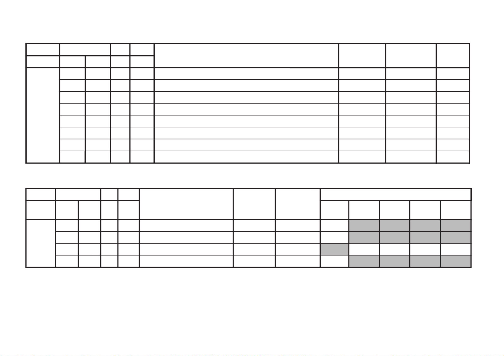
NOTE:
•
shaded items are no data.
• Standard data listed on the Adjustment Item Table are reference values, therefore it may be different for each model and for each mode.
• Note for Different Data Those are the standard data values written on the microprocessor. Therefore, the data values of the modes and stored respectively in the memory.
In case of a device replacement, adjustment by rewriting the data value is necessary for some items.
Data variant depend on models
NOTE: This data with remark **
Category No Name 25"
WHBL 006 PGR 50
007 PGG 50
008 PGB 50
Category No Name Table 25"
SADJ 002 SSHP A859 (TV) 20
A85A (VIDEO) 33
A898 (YUV) 26
Category No Name Table 25"
SADJ 007 COL (Pic Mode 0) 57
Category No Name Table 25"
KV-XR25M50/XR25M80
RM-W104
YC 002 RPO (Others) 02
Category No Name Table 25"
YC 001 RPA (TV) 01
002 RPO TV 02
Category No Name 25"
PICT 004 WHTL 00
Category No Name Table 25"
PICT 008 COR TV (Dyn) 01
TV (Others) 02
Video (Dyn) 00
Video (Others) 01
Category No Name 25"
PICT 011 AAS 01
Category No Name Stereo AV Stereo
SDEM 011 QSS 01 00
– 25 –
KV-XR25M50/XR25M80
RM-W104
NOTE: This data with remark **
Category No Name 5 + 5 XR25
SDSP 002 BBL 00
003 BBH 00
004 BBLW 06
016 BAS 14
017 TRE 14
018 EQ1 10
019 EQ2 09
020 EQ3 00
021 EQ4 01
022 EQ5 10
023 BFCT 00
026 BBHW 00
027 STRE 01
Category No Name Stereo AV Stereo
SDEC 019 EPMD 02 01
020 STDS 31 13
026 DCX1 01 00
027 DCXG 03 00
029 DCLH 06 00
Category No Name Other Country
OPTM 009 LANG 00
Category No Name Stereo AV Stereo
OPTM 012 DCXO 50 70
Category No Name Country
OPTM 014 TSYS 00
Category No Name 25"
OPTM 017 HPRO 05
Category No Name Model Table
off SRS/wow Trusurround I stereo I mono
SDSP 005 SVOF Other 04 11 04 06 04
Models
– 26 –

ITEM INFORMATION
No. OPB1
Item
KV-XR25M50
KV-XR25M80 (ME)
KV-XR25M80
(Saudi Arabia)
SPEED SEARCH (Time of speed search) 00 = disabled (original cycle speed)
TV System Selection 0 = disabled, 1 = enabled
No. OPB2
Speed Search
0
0
0
1
1
1
M/N
0
0
0
KV-XR25M50/XR25M80
RM-W104
L’
0
0
0
L(Euro),
M(GA)
1
1
1
B/G
1
1
1
01 = 4 time speed from the original
10 = 6 time speed from the original
11 = 8 time speed from the original
I
1
1
1
D/K
1
1
1
DEC
79
79
79
Item
KV-XR25M50
KV-XR25M80 (ME)
KV-XR25M80
(Saudi Arabia)
D1
D1 (D1 Terminal) 0 = not available, 1 = available
AV Multi/ (AV Multi Terminal) - JP 0 = not available, 1 = available
PAM Portable Audio Mode - GA 0 = not available, 1 = available
Component (Component [YCbCr] Terminals) 0 = not available, 1 = available
Composite (No. of Composite Terminals) 00 = no composite terminal
(SCART) (No. of SCART Terminals) 01 = 1 composite terminal
SECAM (SECAM Color System) 0 = disabled, 1 = enabled
Color decoding (Color Crystal Selection) 00 = PAL/NTSC/SECAM (Multi)
AV Multi/
PAM(GA)
0
0
0
Component
0
0
0
Composite (SCART)
1
1
1
1
1
1
SECAM
1
1
1
1
1
1
(Euro:no Scart) BX1L:No Video
(Euro:1 Scart) BX1L:2 Video in
10 = 2 composite terminals
(Euro:2 Scart) BX1L:3 Video in
11 = 3 composite terminals
(Euro:no terminal) BX1L:4 Video in
01 = NTSC (3.58MHz)
10 = PAL/NTSC/SECAM (4.43MHz)
11 = PAL/NTSC (Tri-Norma)
Color Decording
0
0
0
0
0
0
DEC
60
60
60
No. OPB3
Item
KV-XR25M50
KV-XR25M80 (ME)
KV-XR25M80
(Saudi Arabia)
HDEV
HDEV (High Deviation Mode) 0 = disabled, 1 = enabled
NICAM ST (NICAM Stereo) 0 = disabled, 1 = enabled
NICAM BI (NICAM Bilingual) 0 = disabled, 1 = enabled
A2 ST/BI (A2 [West German]
Thai Bilingual (A2 [Thai] Bilingual)
US ST (US Stereo) 0 = disabled, 1 = enabled
JP/Korean ST (JP/Korean Stereo) 0 = disabled, 1 = enabled
MONO (Monaural Model) 0 = Stereo (SSD) Model
NICAM ST
0
0
0
NICAM BI
0
0
0
Stereo/Bilingual) 0 = disabled, 1 = enabled
or Force SAP if JP/US ST is active 0 = disabled, 1 = enabled
0
0
0
A2 ST
0
0
0
Thai
Bilingual
0
0
0
US ST
0
0
0
1 = Monuaral Model
JP/
Korean ST
0
0
0
– 27 –
MONO
0
0
0
DEC
0
0
0

KV-XR25M50/XR25M80
RM-W104
No. OPB4
Item
KV-XR25M50
KV-XR25M80 (ME)
KV-XR25M80
(Saudi Arabia)
Firmware/
Firmware (SSD Firmware Downloading) 0 = disabled, 1 = enabled
SMAT Surround Matrix 0 = Active, 1 = Passive
1 spk Models 1 Speaker Models 0 = 2 or 3 Speaker Models,
VM (Velocity Modulation) 0 = disabled, 1 = enabled
Equalizer (5-band Equalizer Model) 0 = Bass/Treble Model, 1 = Equalizer Model
Surround (US/GA Surround Selection) 0 = Off/Simulated/Surround
V-Chip (V-Chip Model) 0 = Channel Block Model (no rating)
TOP (Forced TOP) 0 = Auto Mode (TOP/FLOF), 1 = Forced TOP
TEXT (Teletext Model) 0 = Non-Teletext Model, 1 = Teletext Model
SMAT
1
1
1
1 spk
Models
0
0
0
VM
1
1
1
Equalizer
1
1
1
Surround
0
0
0
V-Chip
0
0
0
1 = 1 speaker Models
1 = Off/Simulated/WOW/TruSurround (US)
1 = Off/Simulated/SRS (3D) Surround (GA)
1 = Parental Control Model (rating)
To p
0
0
0
Te x t
0
0
0
DEC
176
176
176
No. OPB5
Item
KV-XR25M50
KV-XR25M80 (ME)
KV-XR25M80
(Saudi Arabia)
Full
Surround
Full Surround (Full Surround option) 0 = Normal Surround Model
No Surround (No Surround Model) 0 = Surround Model, 1 = Non-Surround Model
Forced 60 (Forced 60Hz in no signal) 0 = 50Hz, 1 = 60Hz
ASD (Automatic Standard Detection) 0 = disabled, 1 = enabled
Tilt (Tilt Correction/PIC Rotation) 0 = disabled, 1 = enabled
IP Plus (Intelligent Picture Plus) 0 = disabled, 1 = enabled
IP (Intelligent Picture) 0 = disabled, 1 = enabled
Wide (Wide Mode/V-Compressed) 0 = disabled, 1 = enabled
Surround
0
0
0
No
0
0
0
Forced 60
0
0
0
ASD
0
0
0
Tilt
1
1
1
IP Plus
1
1
1
1 = Full Surround Model
(Off/simulated/surround/
SRS/WOW/TruSurround)
IP
1
1
1
Wide
1
1
1
DEC
15
15
15
– 28 –

No. OPB6
KV-XR25M50/XR25M80
RM-W104
Item
KV-XR25M50
KV-XR25M80 (ME)
KV-XR25M80
(Saudi Arabia)
GA US
0
0
0
GA US (US Model Destination) 0 = US/CANADA/Latin
Latin (US Model Latin Destination) 0 = US/CANADA (No Volume Figure Display)
Feature 2 (Temporary for BX1L) 0 = Comb Not available
Feature 1 (Temporary for BX1L) 0 = PiP Not Available
OSD Language Selection 01xx = French
(English always available except JP) US 0x1x = Spanish
Latin
Feature 2
0
0
0
0
0
0
Feature 1
0
0
0
OSD Language Selection
1
0
0
US 1x1x = Complicated Chinese
(GA NTSC) 1xx1 = Korean
0
1
1
1 = Taiwan/Korea/Philippine
(Wake-up timer enable)
(GA Surround Spec: OFF,
SIMULATED, SRS)
1 = Latin (Volume Figure Display)
1 = Comb available
1 = PiP available
0
0
0
0xx1 = Portuguese
0
0
0
DEC
8
4
4
1xxx = Simplified Chinese
GA x1xx = Arabic
xx1x = Thai
xxx1 = Vietnamese
0000 = Destination ADE
EU 0001 = Destination BL
0010 = Destination KR
0011 = Destination U
– 29 –
 Loading...